WO2021033517A1 - 電波吸収体フィルム、及びその製造方法 - Google Patents
電波吸収体フィルム、及びその製造方法 Download PDFInfo
- Publication number
- WO2021033517A1 WO2021033517A1 PCT/JP2020/029362 JP2020029362W WO2021033517A1 WO 2021033517 A1 WO2021033517 A1 WO 2021033517A1 JP 2020029362 W JP2020029362 W JP 2020029362W WO 2021033517 A1 WO2021033517 A1 WO 2021033517A1
- Authority
- WO
- WIPO (PCT)
- Prior art keywords
- radio wave
- absorbing layer
- absorber film
- wave absorber
- wave absorbing
- Prior art date
- Legal status (The legal status is an assumption and is not a legal conclusion. Google has not performed a legal analysis and makes no representation as to the accuracy of the status listed.)
- Ceased
Links
Images


Classifications
-
- H—ELECTRICITY
- H05—ELECTRIC TECHNIQUES NOT OTHERWISE PROVIDED FOR
- H05K—PRINTED CIRCUITS; CASINGS OR CONSTRUCTIONAL DETAILS OF ELECTRIC APPARATUS; MANUFACTURE OF ASSEMBLAGES OF ELECTRICAL COMPONENTS
- H05K9/00—Screening of apparatus or components against electric or magnetic fields
- H05K9/0073—Shielding materials
- H05K9/0075—Magnetic shielding materials
-
- H—ELECTRICITY
- H01—ELECTRIC ELEMENTS
- H01Q—ANTENNAS, i.e. RADIO AERIALS
- H01Q17/00—Devices for absorbing waves radiated from an antenna; Combinations of such devices with active antenna elements or systems
-
- B—PERFORMING OPERATIONS; TRANSPORTING
- B05—SPRAYING OR ATOMISING IN GENERAL; APPLYING FLUENT MATERIALS TO SURFACES, IN GENERAL
- B05D—PROCESSES FOR APPLYING FLUENT MATERIALS TO SURFACES, IN GENERAL
- B05D7/00—Processes, other than flocking, specially adapted for applying liquids or other fluent materials to particular surfaces or for applying particular liquids or other fluent materials
- B05D7/24—Processes, other than flocking, specially adapted for applying liquids or other fluent materials to particular surfaces or for applying particular liquids or other fluent materials for applying particular liquids or other fluent materials
-
- B—PERFORMING OPERATIONS; TRANSPORTING
- B32—LAYERED PRODUCTS
- B32B—LAYERED PRODUCTS, i.e. PRODUCTS BUILT-UP OF STRATA OF FLAT OR NON-FLAT, e.g. CELLULAR OR HONEYCOMB, FORM
- B32B7/00—Layered products characterised by the relation between layers; Layered products characterised by the relative orientation of features between layers, or by the relative values of a measurable parameter between layers, i.e. products comprising layers having different physical, chemical or physicochemical properties; Layered products characterised by the interconnection of layers
- B32B7/02—Physical, chemical or physicochemical properties
- B32B7/025—Electric or magnetic properties
-
- H—ELECTRICITY
- H01—ELECTRIC ELEMENTS
- H01F—MAGNETS; INDUCTANCES; TRANSFORMERS; SELECTION OF MATERIALS FOR THEIR MAGNETIC PROPERTIES
- H01F1/00—Magnets or magnetic bodies characterised by the magnetic materials therefor; Selection of materials for their magnetic properties
- H01F1/01—Magnets or magnetic bodies characterised by the magnetic materials therefor; Selection of materials for their magnetic properties of inorganic materials
- H01F1/03—Magnets or magnetic bodies characterised by the magnetic materials therefor; Selection of materials for their magnetic properties of inorganic materials characterised by their coercivity
- H01F1/032—Magnets or magnetic bodies characterised by the magnetic materials therefor; Selection of materials for their magnetic properties of inorganic materials characterised by their coercivity of hard-magnetic materials
- H01F1/10—Magnets or magnetic bodies characterised by the magnetic materials therefor; Selection of materials for their magnetic properties of inorganic materials characterised by their coercivity of hard-magnetic materials non-metallic substances, e.g. ferrites, e.g. [(Ba,Sr)O(Fe2O3)6] ferrites with hexagonal structure
- H01F1/11—Magnets or magnetic bodies characterised by the magnetic materials therefor; Selection of materials for their magnetic properties of inorganic materials characterised by their coercivity of hard-magnetic materials non-metallic substances, e.g. ferrites, e.g. [(Ba,Sr)O(Fe2O3)6] ferrites with hexagonal structure in the form of particles
- H01F1/113—Magnets or magnetic bodies characterised by the magnetic materials therefor; Selection of materials for their magnetic properties of inorganic materials characterised by their coercivity of hard-magnetic materials non-metallic substances, e.g. ferrites, e.g. [(Ba,Sr)O(Fe2O3)6] ferrites with hexagonal structure in the form of particles in a bonding agent
- H01F1/117—Flexible bodies
-
- H—ELECTRICITY
- H01—ELECTRIC ELEMENTS
- H01F—MAGNETS; INDUCTANCES; TRANSFORMERS; SELECTION OF MATERIALS FOR THEIR MAGNETIC PROPERTIES
- H01F3/00—Cores, Yokes, or armatures
- H01F3/02—Cores, Yokes, or armatures made from sheets
-
- H—ELECTRICITY
- H01—ELECTRIC ELEMENTS
- H01Q—ANTENNAS, i.e. RADIO AERIALS
- H01Q17/00—Devices for absorbing waves radiated from an antenna; Combinations of such devices with active antenna elements or systems
- H01Q17/002—Devices for absorbing waves radiated from an antenna; Combinations of such devices with active antenna elements or systems using short elongated elements as dissipative material, e.g. metallic threads or flake-like particles
-
- H—ELECTRICITY
- H05—ELECTRIC TECHNIQUES NOT OTHERWISE PROVIDED FOR
- H05K—PRINTED CIRCUITS; CASINGS OR CONSTRUCTIONAL DETAILS OF ELECTRIC APPARATUS; MANUFACTURE OF ASSEMBLAGES OF ELECTRICAL COMPONENTS
- H05K9/00—Screening of apparatus or components against electric or magnetic fields
- H05K9/0073—Shielding materials
- H05K9/0081—Electromagnetic shielding materials, e.g. EMI, RFI shielding
-
- B—PERFORMING OPERATIONS; TRANSPORTING
- B05—SPRAYING OR ATOMISING IN GENERAL; APPLYING FLUENT MATERIALS TO SURFACES, IN GENERAL
- B05D—PROCESSES FOR APPLYING FLUENT MATERIALS TO SURFACES, IN GENERAL
- B05D2430/00—Component used as a filler in the composition
-
- H—ELECTRICITY
- H01—ELECTRIC ELEMENTS
- H01F—MAGNETS; INDUCTANCES; TRANSFORMERS; SELECTION OF MATERIALS FOR THEIR MAGNETIC PROPERTIES
- H01F1/00—Magnets or magnetic bodies characterised by the magnetic materials therefor; Selection of materials for their magnetic properties
- H01F1/01—Magnets or magnetic bodies characterised by the magnetic materials therefor; Selection of materials for their magnetic properties of inorganic materials
- H01F1/03—Magnets or magnetic bodies characterised by the magnetic materials therefor; Selection of materials for their magnetic properties of inorganic materials characterised by their coercivity
- H01F1/12—Magnets or magnetic bodies characterised by the magnetic materials therefor; Selection of materials for their magnetic properties of inorganic materials characterised by their coercivity of soft-magnetic materials
- H01F1/34—Magnets or magnetic bodies characterised by the magnetic materials therefor; Selection of materials for their magnetic properties of inorganic materials characterised by their coercivity of soft-magnetic materials non-metallic substances, e.g. ferrites
- H01F1/342—Oxides
- H01F1/344—Ferrites, e.g. having a cubic spinel structure (X2+O)(Y23+O3), e.g. magnetite Fe3O4
- H01F1/348—Hexaferrites with decreased hardness or anisotropy, i.e. with increased permeability in the microwave (GHz) range, e.g. having a hexagonal crystallographic structure
Definitions
- the present invention relates to a radio wave absorber film having excellent radio wave absorption performance and a method for manufacturing the same.
- radio waves The use of high-frequency radio waves is widespread in various information communication systems such as mobile phones, wireless LANs, ETC systems, intelligent transportation systems, automobile driving support road systems, and satellite broadcasting.
- the expansion of the use of radio waves in the high frequency band may lead to failure or malfunction of electronic devices due to interference between electronic components.
- a method of absorbing unnecessary radio waves by a radio wave absorber is adopted.
- radio wave absorbers are used in order to reduce the influence of unnecessary radio waves that should not be originally received.
- various radio wave absorbers capable of satisfactorily absorbing radio waves in a high frequency band have been proposed.
- a radio wave absorbing sheet containing a carbon nanocoil and a resin for example, Patent Document 1 is known.
- radio waves in the 76 GHz band are used in an in-vehicle radar for detecting an inter-vehicle distance and the like. It is predicted that the use of radio waves in a high frequency band of, for example, 100 GHz or more will be expanded in various applications, not limited to automobile driving support systems. Therefore, a radio wave absorber capable of satisfactorily absorbing radio waves in the 76 GHz band or a higher frequency band is desired.
- Radio wave absorber capable of satisfactorily absorbing radio waves in a wide range in a high frequency band
- a radio wave absorbing layer containing a magnetic crystal made of ⁇ -Fe 2 O 3 iron oxide is provided.
- Radio wave absorbers have been proposed (for example, Patent Document 2 and Non-Patent Documents 1 to 3).
- the present invention has been made in view of the above-mentioned problems of the prior art, and an object of the present invention is to provide a radio wave absorber film which is thin and has excellent radio wave absorption performance, and a method for manufacturing the radio wave absorber film.
- the present inventors include a magnetic material and a binder resin in the radio wave absorbing layer, and use an aromatic ester-urethane copolymer as the binder resin. It was found that the above-mentioned problems could be solved, and the present invention was completed.
- the first aspect of the present invention is a radio wave absorber including a radio wave absorbing layer formed on a base material layer.
- the radio wave absorbing layer contains a magnetic material and a binder resin,
- the binder resin is a radio wave absorber film containing an aromatic ester-urethane copolymer.
- a second aspect of the present invention is to apply a paste containing a magnetic material and a binder resin on a base material layer to form a coating film, and then dry the coating film to form a radio wave absorbing layer.
- Including absorption layer forming step A method for producing a radio wave absorber film, wherein the binder resin contains an aromatic ester-urethane copolymer.
- radio wave absorber film which is a thin film and has excellent radio wave absorption performance, and a method for manufacturing the radio wave absorber film.
- the radio wave absorber film includes a radio wave absorbing layer formed on the base material layer.
- the radio wave absorbing layer contains a magnetic material and a binder resin.
- the binder resin contains an aromatic ester-urethane copolymer.
- a frequency band of 30 GHz (GHz) or higher, preferably 30 GHz or higher and 300 GHz or lower, more preferably 40 GHz or higher and 200 GHz or lower is used.
- GHz GHz
- a peak having an absolute value of 30 dB or more exists in the amount of reflection attenuation measured from the side of the surface provided with the radio wave absorbing layer.
- the value of the transmission attenuation is a value measured under the conditions measured in the examples described later.
- the shape of the radio wave absorber film may have a curved surface or may be composed of only a flat surface, and a flat plate shape is preferable.
- the thickness of the radio wave absorber film is preferably 1000 ⁇ m or less, more preferably 900 ⁇ m or less, further preferably 450 ⁇ m or less, and further preferably 200 ⁇ m or less from the viewpoint of thinning or downsizing the film without impairing the effect of the present invention. Is particularly preferable.
- the thickness of the radio wave absorber film may be uniform or non-uniform.
- the radio wave absorbing layer contains a binder resin together with a magnetic material.
- the binder resin contains an aromatic ester-urethane copolymer.
- the film thickness of the radio wave absorbing layer is not particularly limited as long as the object of the present invention is not impaired.
- the film thickness of the radio wave absorbing layer is preferably 100 ⁇ m or less, and more preferably 50 ⁇ m or less, from the viewpoint of the balance between the thinning of the radio wave absorber film and the radio wave absorbing performance.
- the lower limit of the thickness of the radio wave absorbing layer is not particularly limited as long as the effect of the present invention is not impaired, and examples thereof include 1 ⁇ m and more and 10 ⁇ m and more.
- the thickness of the radio wave absorbing layer may be uniform or non-uniform.
- the radio wave absorbing layer contains a binder resin together with a magnetic material.
- the binder resin contains an aromatic ester-urethane copolymer.
- the glass transition temperature of the binder resin is preferably 100 ° C. or lower, more preferably 0 ° C. or lower. Therefore, the glass transition temperature of the aromatic ester-urethane copolymer is preferably 100 ° C. or lower, more preferably 0 ° C. or lower.
- the aromatic ester-urethane copolymer contains an ester bond (-CO-O-) and a urethane bond (-NH-CO-O-), and contains an aromatic group in the main chain skeleton.
- the aromatic group in the main chain skeleton may be an aromatic hydrocarbon group or a heterocyclic aromatic group, and an aromatic hydrocarbon group is preferable.
- the aromatic ester-urethane copolymer may be a random copolymer in which an ester bond and a urethane bond are randomly introduced in the molecular chain, and one or more ester blocks and one or more urethane blocks. It may be a block copolymer composed of.
- the method for producing the aromatic ester-urethane copolymer is not particularly limited.
- the aromatic ester-urethane copolymer is typically one selected from the group consisting of a diol component (a1), a dicarboxylic acid (a2), a hydroxycarboxylic acid component (a3), and a diisocyanate component (a4). It can be produced by polymerizing the above monomers in one step or in multiple steps.
- the dicarboxylic acid component (a2) and the hydroxycarboxylic acid component (a3) may be used as an ester derivative such as a methyl ester or an ethyl ester, an ester such as a carboxylic acid halide such as a carboxylic acid chloride, or a urethane-forming derivative.
- the above-mentioned monomer used for producing an aromatic ester-urethane copolymer contains a divalent hydrocarbon group having a non-branched structure and two functional groups selected from the group consisting of a hydroxyl group, a carboxy group, and an isocyanate group. It is preferably a bound compound.
- the divalent hydrocarbon group having a non-branched structure include an alkylene group, an alkenylene group, an alkynylene group, an arylene group, or a combination of these groups.
- the alkylene group, alkenylene group, and alkynylene group preferably have a linear structure.
- the divalent hydrocarbon group having a non-branched structure is an alkylene group, an alkenylene group, or an alkynylene group
- the number of carbon atoms of these groups is preferably 1 or more and 8 or less, more preferably 2 or more and 6 or less, and 2 or more. 4 or less is more preferable.
- the arylene group is preferably a phenylene group or a naphthylene group, more preferably a phenylene group, and even more preferably a p-phenylene group.
- the alkylene group and the arylene group and the combination of the alkylene group and the arylene group are preferable.
- diol component (a1) examples include ethylene glycol, 1,3-propanediol, 1,4-butanediol, neopentyl glycol, 1,6-hexanediol, 1,4-cyclohexanedimethanol, and Examples thereof include 1,5-pentanediol.
- Suitable specific examples of the dicarboxylic acid (a2) include terephthalic acid, isophthalic acid, 2,6-naphthalenedicarboxylic acid, 2,7-naphthalenedicarboxylic acid, 1,4-naphthalenedicarboxylic acid, and 1,4-cyclohexanedicarboxylic acid.
- hydroxycarboxylic acid component (a3) include 4-hydroxybenzoic acid, 3-hydroxybenzoic acid, 6-hydroxynaphthalene-2-carboxylic acid, glycolic acid, lactic acid, ⁇ -hydroxybutyric acid and the like. Be done.
- diisocyanate component (a4) examples include ethylene diisocyanate, trimethylene diisocinenate, tetramethylene diisocyanate, hexamethylene diisocyanate, isophorone diisocyanate, m-xylylene diisocyanate, p-phenylenediocyanate, tolylene diisocyanate, 4 , 4'-diphenylmethane diisocyanate, and 1,5-naphthalenediisocyanate.
- the weight average molecular weight (Mw) of the aromatic ester-urethane copolymer is preferably 5000 or more and 500,000 or less, and more preferably 10,000 or more and 200,000 or less.
- the weight average molecular weight (Mw) is the polystyrene-equivalent weight average molecular weight measured by GPC.
- Examples of commercially available products of aromatic ester-urethane copolymers include the Byron series (trade name) (manufactured by Toyobo Co., Ltd.). More specifically, Byron UR-1400, Byron UR-1410, Byron UR-1700, Byron UR-2300, Byron UR-3200, Byron UR-3210, Byron UR-3500, Byron UR-6100, Byron UR-8300. , And Byron UR-8700 and the like can be preferably used.
- the binder resin may contain a resin other than the aromatic ester-urethane copolymer as long as the object of the present invention is not impaired.
- the type of other resin is not particularly limited as long as the object of the present invention is not impaired.
- the other resin may be an elastic material such as an elastomer or rubber.
- the other resin may be a thermoplastic resin or a curable resin.
- the curable resin may be a photocurable resin or a thermosetting resin.
- thermoplastic resin examples include polyacetal resin, polyamide resin, polycarbonate resin, polyester resin (polybutylene terephthalate, polyethylene terephthalate, polyarylate, etc.), FR-AS resin, FR-ABS resin.
- AS resin AS resin, ABS resin, polyphenylene oxide resin, polyphenylene sulfide resin, polysulfone resin, polyethersulfone resin, polyether ether ketone resin, fluororesin, polyimide resin, polyamideimide resin, polyamidebismaleimide resin, polyetherimide resin, Polybenzoxazole resin, polybenzothiazole resin, polybenzoimidazole resin, BT resin, polymethylpentene, ultrahigh molecular weight polyethylene, FR-polypropylene, cellulose resin (for example, methylcellulose, ethylcellulose), (meth) acrylic resin (polymethylmethacrylate) Etc.), and polystyrene and the like.
- Phenol resin, melamine resin, epoxy resin, alkyd resin and the like can be mentioned as a preferable example when the other resin is a thermosetting resin.
- the photocurable resin resins obtained by photocuring various vinyl monomers and monomers having unsaturated bonds such as various (meth) acrylic acid esters can be used.
- the other resin is an elastic material
- the other resin is an elastic material
- an olefin-based elastomer, a styrene-based elastomer, a polyamide-based elastomer, a polyester-based elastomer, and a polyurethane-based elastomer examples include an olefin-based elastomer, a styrene-based elastomer, a polyamide-based elastomer, a polyester-based elastomer, and a polyurethane-based elastomer.
- the ratio of the mass of the other resin to the total mass of the binder resin is not particularly limited as long as the object of the present invention is not impaired.
- the ratio of the mass of the other resin to the total mass of the binder resin is preferably, for example, 20% by mass or less, more preferably 10% by mass or less, and 5% by mass or less, because it is easy to obtain a radio wave absorber film having the desired performance. Is even more preferable, 1% by mass or less is even more preferable, and 0% by mass is most preferable.
- the content of the binder resin in the radio wave absorbing layer is not particularly limited as long as the object of the present invention is not impaired.
- the content of the binder resin is preferably 5% by mass or more and 30% by mass or less, and more preferably 10% by mass or more and 25% by mass or less with respect to the solid content mass of the radio wave absorbing layer.
- the type of magnetic material is not particularly limited as long as the radio wave absorber film exhibits desired radio wave absorption characteristics.
- the magnetic material is preferably a magnetic material that magnetically resonates in a frequency band of 30 GHz or more, and more preferably a magnetic material that magnetically resonates in a frequency band of 30 GHz or more and 300 GHz or less from the viewpoint of being able to absorb radio waves having a high frequency of millimeter wave band or more. preferable.
- Examples of the magnetic resonance include magnetic resonance based on precession when electrons in atoms spin in a frequency band higher than the millimeter wave band. Natural magnetic resonance due to the gyro magnetic effect based on precession in the frequency band above the millimeter wave band is preferable.
- the magnetic material is not particularly limited as long as it can absorb high frequency radio waves in the millimeter wave band or higher.
- Preferred magnetic materials include magnetic materials containing at least one selected from the group consisting of epsilon-type iron oxide, barium ferrite magnetic materials, and strontium ferrite magnetic materials. The epsilon-type iron oxide will be described below.
- Any ⁇ -Fe 2 O 3 crystal can be used. It has the same crystal structure and space group as ⁇ -Fe 2 O 3, and in which a part of the Fe site of ⁇ -Fe 2 O 3 crystals is substituted by an element M other than Fe, wherein epsilon-M x A crystal represented by Fe 2-x O 3 and having x of 0 or more and 2 or less (preferably 0 or more and less than 2) will be described later.
- ⁇ -M x Fe 2-x O 3 in which a part of the Fe site of the ⁇ -Fe 2 O 3 crystal is substituted with the substitution element M is also referred to as "M-substituted ⁇ -Fe 2 O 3". ..
- the particle size of the particles having the ⁇ -Fe 2 O 3 crystal and / or the M-substituted ⁇ -Fe 2 O 3 crystal in the magnetic phase is not particularly limited as long as the object of the present invention is not impaired.
- particles having a magnetic crystal of epsilon-type iron oxide as a magnetic phase produced by a method described later have an average particle diameter of 5 nm or more and 200 nm or less measured from a TEM (transmission electron microscope) photograph. is there.
- the coefficient of variation (standard deviation of particle size / average particle size) of particles having a magnetic crystal of epsilon-type iron oxide in a magnetic layer is in the range of less than 80%, which is relatively relatively high. It is a group of fine particles with a uniform particle size.
- powder of such magnetic particles of epsilon-type iron oxide that is, particles having ⁇ -Fe 2 O 3 crystals and / or M-substituted ⁇ -Fe 2 O 3 crystals in the magnetic phase
- the "magnetic phase” here is the part responsible for the magnetism of the powder.
- Having a ⁇ -Fe 2 O 3 crystal and / or an M-substituted ⁇ -Fe 2 O 3 crystal as a magnetic phase means that the magnetic phase is an ⁇ -Fe 2 O 3 crystal and / or an M-substituted ⁇ -Fe 2 O 3 It means that it is composed of crystals, and includes the case where impurity magnetic crystals that are unavoidable in production are mixed in the magnetic phase.
- the magnetic crystal of epsilon-type iron oxide is an impurity crystal of iron oxide having a different space group and oxidation state from the ⁇ -Fe 2 O 3 crystal (specifically, ⁇ -Fe 2 O 3 and ⁇ -Fe 2 O). 3, FeO, and Fe 3 O 4, and part of Fe in these crystals may include crystals) substituted with another element.
- the magnetic crystal of epsilon-type iron oxide contains impurity crystals, it is preferable that the magnetic crystal of ⁇ -Fe 2 O 3 and / or M-substituted ⁇ -Fe 2 O 3 is the main phase.
- the ratio of the magnetic crystals of ⁇ -Fe 2 O 3 and / or M-substituted ⁇ -Fe 2 O 3 among the magnetic crystals of epsilon iron oxide constituting the radio wave absorbing material is the molar ratio as a compound. It is preferably 50 mol% or more.
- the abundance ratio of crystals can be determined by analysis by the Rietveld method based on the X-ray diffraction pattern.
- a non-magnetic compound such as silica (SiO 2 ) formed in the sol-gel process may be attached around the magnetic phase.
- M substitution ⁇ -Fe 2 O 3 Be the same crystal and space group as ⁇ -Fe 2 O 3, as long as conditions are satisfied in a part of the Fe site of ⁇ -Fe 2 O 3 crystal is one which is substituted with an element M other than Fe,
- the type of element M in the M-substituted ⁇ -Fe 2 O 3 is not particularly limited.
- the M-substituted ⁇ -Fe 2 O 3 may contain a plurality of types of elements M other than Fe.
- the element M include In, Ga, Al, Sc, Cr, Sm, Yb, Ce, Ru, Rh, Ti, Co, Ni, Mn, Zn, Zr, and Y.
- In, Ga, Al, Ti, Co and Rh are preferable.
- M is Al
- x is preferably in the range of 0 or more and less than 0.8, for example.
- M is Ga x is preferably in the range of 0 or more and less than 0.8, for example.
- M is In x is preferably in the range of 0 or more and less than 0.3, for example.
- M is Rh x is preferably in the range of 0 or more and less than 0.3, for example.
- M is Ti and Co x is preferably in the range of 0 or more and less than 1.
- the frequency at which the amount of radio wave absorption is maximum can be adjusted by adjusting at least one of the type and the amount of substitution of the element M in the M substitution ⁇ -Fe 2 O 3.
- Such an M-substituted ⁇ -Fe 2 O 3 magnetic crystal can be synthesized, for example, by a step of combining the inverse micelle method and the sol-gel method and a firing step described later. Further, an M-substituted ⁇ -Fe 2 O 3 magnetic crystal can be synthesized by a step of combining a direct synthesis method and a sol-gel method and a firing step as disclosed in Japanese Patent Application Laid-Open No. 2008-174405. ..
- the M-substituted ⁇ -Fe 2 O 3 magnetic crystal can be obtained by a step combining the inverse micelle method and the sol-gel method and a firing step as described in the above.
- micelle solution I raw material micelle
- micelle solution II neutralizing agent micelle
- a silica coat is applied to the surface of the iron hydroxide fine particles generated in the micelle by the sol-gel method.
- the iron hydroxide fine particles provided with the silica-coated layer are separated from the liquid and then subjected to heat treatment in an atmospheric atmosphere at a predetermined temperature (within the range of 700 to 1300 ° C.). By this heat treatment , fine particles of ⁇ -Fe 2 O 3 crystals are obtained.
- an M-substituted ⁇ -Fe 2 O 3 magnetic crystal is produced as follows.
- iron (III) nitrate as an iron source and M nitrate (in the case of Al, aluminum nitrate) as an M element source for substituting a part of iron in the aqueous phase of micelle solution I having n-octane as an oil phase.
- M nitrate in the case of Al, aluminum nitrate
- M element source for substituting a part of iron in the aqueous phase of micelle solution I having n-octane as an oil phase.
- III 9 hydrate, in the case of Ga, gallium nitrate (III) hydrate, in the case of In, indium nitrate (III) trihydrate, in the case of Ti and Co, hydration of titanium sulfate (IV)
- cobalt (II) nitrate hexahydrate), and a surfactant for example, cetyltrimethylammonium bromide
- nitrate of alkaline earth metal Ba, Sr, Ca, etc.
- This nitrate functions as a shape control agent.
- the alkaline earth metal is present in the liquid, rod-shaped M-substituted ⁇ -Fe 2 O 3 magnetic crystal particles are finally obtained.
- particles of M-substituted ⁇ -Fe 2 O 3 magnetic crystals that are close to spherical can be obtained.
- the alkaline earth metal added as a shape control agent may remain on the surface layer of the generated M-substituted ⁇ -Fe 2 O 3 magnetic crystal.
- An aqueous ammonia solution is used as the aqueous phase of the micelle solution II having n-octane as the oil phase.
- the sol-gel method After mixing the micelle solutions I and II, apply the sol-gel method. That is, stirring is continued while dropping silane (for example, tetraethyl orthosilane) into the mixture of micelle solutions, and the reaction for producing iron hydroxide or iron hydroxide containing the element M is allowed to proceed in the micelle. As a result, the particle surface of the fine iron hydroxide precipitate formed in the micelle is coated with silica generated by the hydrolysis of silane.
- silane for example, tetraethyl orthosilane
- the particle powder obtained by separating, washing, and drying the silica-coated M element-containing iron hydroxide particles from the liquid is charged into a furnace and placed in air at 700 ° C. or higher and 1300 ° C. or lower, preferably 900 ° C.
- Heat treatment (firing) is performed in a temperature range of 1200 ° C. or lower, more preferably 950 ° C. or higher and 1150 ° C. or lower.
- the oxidation reaction proceeds in the silica coating, and the fine particles of the fine M element-containing iron hydroxide are changed into the fine M-substituted ⁇ -Fe 2 O 3 particles.
- the presence of the silica coat is not a crystal of ⁇ -Fe 2 O 3 or ⁇ -Fe 2 O 3 , but an M-substituted ⁇ -Fe 2 O having the same space group as ⁇ -Fe 2 O 3. 3 It contributes to the formation of crystals and also has the effect of preventing the sintering of particles. Further, when an appropriate amount of alkaline earth metal coexists, the particle shape tends to grow into a rod shape.
- the M-substituted ⁇ -Fe 2 O 3 magnetic crystal is obtained by a step of combining the direct synthesis method and the sol-gel method and a firing step as disclosed in Japanese Patent Application Laid-Open No. 2008-174405. It can be synthesized economically.
- a precursor consisting of an iron hydroxide (some of which may be replaced by another element) is formed.
- a sol-gel method is applied to form a silica coating layer on the surface of the precursor particles.
- heat treatment is performed at a predetermined temperature to obtain fine particles of M-substituted ⁇ -Fe 2 O 3 magnetic crystals.
- iron oxide crystals having different space groups and oxidation states from the ⁇ -Fe 2 O 3 crystals may be generated.
- the most universal polymorphs having a composition of Fe 2 O 3 but different crystal structures are ⁇ -Fe 2 O 3 and ⁇ -Fe 2 O 3 .
- examples of other iron oxides include FeO and Fe 3 O 4 .
- the inclusion of such impurity crystals is not preferable in order to bring out the characteristics of the M-substituted ⁇ -Fe 2 O 3 crystals as high as possible, but it is allowed as long as the effects of the present invention are not impaired.
- the coercive force H c of M-substituted ⁇ -Fe 2 O 3 magnetic crystal is changed according to the substitution amount by the substituting element M.
- the substitution amount by substitution element M in the M-substituted ⁇ -Fe 2 O 3 magnetic crystal it is possible to adjust the coercive force H c of M-substituted ⁇ -Fe 2 O 3 magnetic crystal.
- the substituent element M if the Ga or the like is used as the substituent element M, the more amount of substitution increases, the coercive force H c of M-substituted ⁇ -Fe 2 O 3 magnetic crystal is lowered.
- Rh etc.
- the substituent element M As a substituent element M, the more amount of substitution increases, the coercive force H c of M-substituted ⁇ -Fe 2 O 3 magnetic crystal increases. From the viewpoint of easily adjusting the coercive force H c of M-substituted ⁇ -Fe 2 O 3 magnetic crystal Depending on the substitution amount by the substituent element M, the substituent element M, Ga, Al, In, Ti, Co and Rh are preferred ..
- wave absorption amount of epsilon-type iron oxide is also shifted frequency of the peak with a maximum in the low frequency side or the higher frequency side. That is, the frequency of the peak of the radio wave absorption amount can be controlled by the substitution amount of the M element.
- radio wave absorber In the case of a generally used radio wave absorber, the amount of absorption becomes almost zero if the incident angle or frequency of the radio wave deviates from the designed value. On the other hand, when epsilon-type iron oxide is used, radio wave absorption is exhibited in a wide frequency range and radio wave incident angle even if the value deviates slightly. Therefore, it is possible to provide a radio wave absorption layer capable of absorbing radio waves in a wide frequency band.
- the particle size of epsilon-type iron oxide can be controlled, for example, by adjusting the heat treatment (calcination) temperature in the above step.
- the average particle size of epsilon-type iron oxide is more preferably 10 nm or more, and more preferably 20 nm or more.
- the average particle size which is the number average particle size
- the average particles are average particles with the diameter in the major axis direction of the particles observed on the TEM image as the diameter of the particles. Calculate the diameter.
- the number of particles to be measured is not particularly limited as long as it is a sufficiently large number for calculating the average value, but it is preferably 300 or more.
- a silica coat coated on the surface of the iron hydroxide fine particles by the sol-gel method may be present on the surface of the M-substituted ⁇ -Fe 2 O 3 magnetic crystal after the heat treatment (calcination).
- a non-magnetic compound such as silica
- the non-magnetic compound include silica and heat-resistant compounds such as alumina and zirconia.
- the non-magnetic compound adhered is silica, by weight of Si in M-substituted ⁇ -Fe 2 O 3 magnetic crystals, the mass of the substitution elements M in M-substituted ⁇ -Fe 2 O 3 magnetic crystal, the sum of the mass of Fe On the other hand, it is preferably 100% by mass or less. Part or most of the silica adhering to the M-substituted ⁇ -Fe 2 O 3 magnetic crystal can be removed by immersing in an alkaline solution. The amount of silica adhered can be adjusted to an arbitrary amount by such a method.
- the content of the magnetic substance in the radio wave absorbing layer is not particularly limited as long as the object of the present invention is not impaired.
- the content of the magnetic material is preferably 30% by mass or more, more preferably 40% by mass or more, particularly preferably 60% by mass or more, and 60% by mass or more and 91% by mass or less with respect to the solid content mass of the radio wave absorbing layer. Most preferred.
- the relative permittivity of the radio wave absorbing layer is not particularly limited, but is preferably 6.5 or more and 65 or less, more preferably 10 or more and 50 or less, and further preferably 15 or more and 30 or less.
- the method of adjusting the relative permittivity of the radio wave absorbing layer is not particularly limited. Examples of the method for adjusting the relative permittivity of each radio wave absorbing layer include a method in which the radio wave absorbing layer contains a dielectric powder and the content of the dielectric powder is adjusted.
- the dielectric include barium titanate, strontium titanate, calcium titanate, magnesium titanate, bismuth titanate, zirconium titanate, zinc titanate, and titanium dioxide.
- the radio wave absorbing layer may contain a combination of a plurality of types of dielectric powders.
- the particle size of the dielectric powder used for adjusting the relative permittivity of the radio wave absorbing layer is not particularly limited as long as the object of the present invention is not impaired.
- the average particle size of the dielectric powder is preferably 1 nm or more and 100 nm or less, and more preferably 5 nm or more and 50 nm or less.
- the average particle size of the dielectric powder is the number average particle size of the primary particles of the dielectric powder observed by an electron microscope.
- the amount of the dielectric powder used is not particularly limited as long as the relative permittivity of the radio wave absorbing layer is within a predetermined range.
- the amount of the dielectric powder used is preferably 0% by mass or more and 20% by mass or less, and more preferably 5% by mass or more and 10% by mass or less with respect to the solid content mass of each radio wave absorbing layer.
- the relative permittivity can be adjusted by including carbon nanotubes in the radio wave absorption layer.
- the carbon nanotubes may be used in combination with the above-mentioned dielectric powder.
- the amount of carbon nanotubes compounded in the radio wave absorbing layer is not particularly limited as long as the relative permittivity of the radio wave absorbing layer is within the above-mentioned predetermined range. However, since carbon nanotubes are also conductive materials, if the amount of carbon nanotubes used is excessive, the radio wave absorption characteristics provided by the radio wave absorption layer may be impaired.
- the amount of carbon nanotubes used is preferably 0% by mass or more and 20% by mass or less, and more preferably 1% by mass or more and 10% by mass or less, based on the solid content mass of the radio wave absorbing layer.
- the relative magnetic permeability of the radio wave absorbing layer is not particularly limited, but is preferably 1.0 or more and 1.5 or less.
- the method of adjusting the relative magnetic permeability of the radio wave absorbing layer is not particularly limited.
- a method for adjusting the relative magnetic permeability of each radio wave absorbing layer as described above, a method for adjusting the amount of substitution by the substitution element M in the epsilon-type iron oxide, a method for adjusting the content of the magnetic substance in the radio wave absorbing layer, and the like can be mentioned. Be done.
- the radio wave absorbing layer may contain a dispersant for the purpose of satisfactorily dispersing the magnetic substance, the substance added for adjusting the relative permittivity and the relative magnetic permeability in the radio wave absorbing layer.
- the dispersant may be uniformly mixed with the above magnetic material, polymer and the like.
- the dispersant may be blended in the binder resin.
- the magnetic substance, the substance added for adjusting the relative permittivity and the relative magnetic permeability, which has been pretreated with a dispersant may be blended with the material constituting the radio wave absorbing layer.
- a dispersant is not particularly limited as long as it does not interfere with the object of the present invention.
- a dispersant can be selected from various dispersants conventionally used for dispersing various inorganic fine particles and organic fine particles.
- the dispersant include a silane coupling agent (for example, phenyltrimethoxysilane), a titanate coupling agent, a zirconate coupling agent, an aluminate coupling agent, and the like.
- a silane coupling agent for example, phenyltrimethoxysilane
- a titanate coupling agent for example, phenyltrimethoxysilane
- a zirconate coupling agent for example, an aluminate coupling agent, and the like.
- the content of the dispersant is not particularly limited as long as it does not interfere with the object of the present invention.
- the content of the dispersant is preferably 0.1% by mass or more and 30% by mass or less, more preferably 1% by mass or more and 15% by mass or less, and 1% by mass or more and 10% by mass with respect to the solid content mass of the radio wave absorbing layer. The following are particularly preferred.
- the radio wave absorbing layer may contain various additives other than the above-mentioned components as long as the object of the present invention is not impaired.
- additives that can be contained in the radio wave absorbing layer include colorants, antioxidants, ultraviolet absorbers, flame retardants, flame retardants, plasticizers, and surfactants. These additives are used in consideration of the amount conventionally used, as long as the object of the present invention is not impaired.
- the radio wave absorbing layer can be formed with high efficiency without any limitation on the thickness, and the radio wave absorbing layer can be formed directly on the base material layer.
- the method of forming using is preferable.
- the paste for forming a radio wave absorbing layer preferably contains the binder resin and the magnetic material.
- the paste for forming a radio wave absorbing layer may contain a substance added for adjusting the relative permittivity, the relative magnetic permeability, and the like, and other components described above for the radio wave absorbing layer.
- the binder resin contains a curable resin
- the paste for forming the radio wave absorbing layer contains a compound that is a precursor of the curable resin.
- the paste for forming the radio wave absorbing layer contains a curing agent, a curing accelerator, a polymerization initiator and the like, if necessary.
- the coating film may be exposed or heated as necessary to form a radio wave absorbing layer.
- the paste for forming a radio wave absorbing layer preferably further contains a dispersion medium.
- a dispersion medium water, an organic solvent, and an aqueous solution of the organic solvent can be used.
- an organic solvent is preferable because it is easy to dissolve organic components, has low latent heat of vaporization, and is easy to remove by drying.
- organic solvent used as the dispersion medium are N, N, N', N'-tetramethylurea (TMU), N-methyl-2-pyrrolidone (NMP), N, N-dimethylacetamide (N, N-dimethylacetamide).
- Saturated aliphatic monocarboxylic acid alkyl esters such as acetic acid-n-butyl and amyl acetate
- Lactic acid esters such as ethyl lactate and lactate-n-butyl
- Ketones such as acetone, methyl ethyl ketone, cyclohexanone, acetophenone and benzophenone Classes
- the solid content concentration of the radio wave absorbing layer forming paste is appropriately adjusted according to the method of applying the radio wave absorbing layer forming paste, the thickness of the radio wave absorbing layer, and the like.
- the solid content concentration of the paste for forming a radio wave absorbing layer is preferably 3% by mass or more and 60% by mass or less, and more preferably 10% by mass or more and 50% by mass or less.
- the solid content concentration of the paste is a value calculated by adding the mass of the components not dissolved in the dispersion medium and the mass of the components dissolved in the dispersion medium as the mass of the solid content.
- the above-mentioned radio wave absorbing layer is laminated on the base material layer.
- the base material layer may be a layer containing any base material as long as the effects of the present invention are not impaired, and examples thereof include a layer containing a resin.
- the resin include polyethylene terephthalate (PET), polyethylene naphthalate (PEN), acrylic (PMMA), polycarbonate (PC), cycloolefin polymer (COP), polyether sulfone, polyimide, polyamideimide and the like.
- PET is preferable because it has excellent heat resistance and has a good balance between dimensional stability and cost.
- the shape of the base material layer may have a curved surface or may be composed of only a flat surface, and a flat plate shape is preferable.
- the thickness of the base material layer is preferably 800 ⁇ m or less, more preferably 500 ⁇ m or less, further preferably 300 ⁇ m or less, and further preferably 150 ⁇ m or less from the viewpoint of thinning or downsizing the film without impairing the effect of the present invention. Is particularly preferable.
- the lower limit of the thickness of the base material layer is not particularly limited as long as the effect of the present invention is not impaired, and examples thereof include 1 ⁇ m or more, 10 ⁇ m or more, and 50 ⁇ m or more.
- a metal layer may be provided on the surface of the base material layer opposite to the surface on which the radio wave absorbing layer is provided. When the metal layer is provided, the radio waves reflected by the metal layer can be attenuated.
- the metal constituting the metal layer for example, aluminum, titanium, SUS, copper, brass, silver, gold, platinum and the like are preferable.
- the thickness of the metal layer is not particularly limited, and from the viewpoint of thinning the radio wave absorber film, 600 ⁇ m or less is preferable, 400 ⁇ m or less is more preferable, 100 ⁇ m or less is further preferable, and 50 ⁇ m or less is particularly preferable.
- the lower limit of the thickness of the metal layer is not particularly limited as long as the effect of the present invention is not impaired, and examples thereof include 0.1 ⁇ m or more, 1 ⁇ m or more, 5 ⁇ m or more, and 10 ⁇ m or more.
- the radio wave absorber film includes various elements (vehicle-mounted elements, high-frequency antenna elements, etc.) in various information communication systems such as mobile phones, wireless LANs, ETC systems, intelligent transportation systems, automobile driving support road systems, and satellite broadcasting. It can be preferably used as a film for absorbing radio waves used in.).
- the method for producing the above-mentioned radio wave absorber film is not particularly limited as long as the radio wave absorber film having a predetermined structure can be produced.
- a preferred method is a step of forming a radio wave absorbing layer, in which a paste containing a magnetic material and a binder resin is applied onto the base material layer to form a coating film, and then the coating film is dried to form a radio wave absorbing layer. Examples include methods including. As described above, the binder resin contains an aromatic ester-urethane copolymer.
- the above-mentioned radio wave absorbing layer forming paste can be used as the paste used in the radio wave absorbing layer forming step.
- the method of applying the radio wave absorbing layer forming paste on the base material layer is not particularly limited as long as the radio wave absorbing layer having a desired thickness can be formed.
- the coating method include a spray coating method, a dip coating method, a roll coating method, a curtain coating method, a spin coating method, a screen printing method, a doctor blade method, an applicator method and the like.
- the radio wave absorption layer can be formed by drying the coating film formed by the above method to remove the dispersion medium.
- the film thickness of the coating film is appropriately adjusted so that the thickness of the radio wave absorbing layer obtained after drying becomes a desired thickness.
- the drying method is not particularly limited, and for example, (1) a method of drying on a hot plate at a temperature of 80 ° C.
- Examples thereof include a method of leaving the solvent at room temperature for several hours to several days, and (3) a method of removing the solvent by putting it in a warm air heater or an infrared heater for several tens of minutes to several hours.
- the method for manufacturing a radio wave absorber film is to cut a laminate having a base material layer and a radio wave absorbing layer obtained in the radio wave absorbing layer forming step to obtain a radio wave absorber film having a predetermined size.
- the cutting step may be included.
- the radio wave absorbing layer of the present invention contains an aromatic ester-urethane copolymer as a binder resin, it has good crack resistance. Therefore, even if the radio wave absorber film is cut, cracks are unlikely to occur in the radio wave absorbing layer on the cut surface.
- Example 1 (Preparation of paste for forming radio wave absorption layer) To 35 parts by mass of TMU, 40 parts by mass of the following epsilon-type iron oxide, 2 parts by mass of the carbon nanotube (CNT) below, 3 parts by mass of the dispersant below, and 20 parts by mass of the binder resin solution below were added. The mixture was stirred with a rotation / revolution mixer to uniformly dissolve or disperse each component to obtain a paste for forming a radio wave absorbing layer.
- CNT carbon nanotube
- ⁇ -Ga 0.45 Fe 1.55 O 3 was used as the epsilon-type iron oxide.
- the average particle size of epsilon-type iron oxide was 20 nm or more and 30 nm or less.
- the CNT multi-walled carbon nanotubes having a major axis of 150 nm (trade name: VGCF-H; manufactured by Showa Denko KK) were used. Phenyltrimethoxysilane was used as the dispersant.
- an aromatic ester-urethane copolymer manufactured by Toyobo Co., Ltd., consisting of Byron UR-3201, glass transition temperature -3 ° C, weight average molecular weight 40,000, resin 5 parts by mass and methyl ethyl ketone 15 parts by mass was used. Using.
- the PET film (thickness 125 ⁇ m) was coated with an applicator using the above-mentioned paste for forming a radio wave absorbing layer. Then, the coating film was dried under the conditions of 90 ° C. for 10 minutes and 130 ° C. for 10 minutes to form a radio wave absorbing layer having a thickness of 35 ⁇ m to obtain a radio wave absorber film.
- the radio wave absorber film obtained immediately after drying was cut into a square shape of 5 cm square to prepare the following test pieces for evaluation.
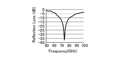
- FIG. 1 shows the reflection attenuation amount (Reflection Loss (dB)) of the radio wave absorber film of Example 1 in the frequency range of 50 to 100 GHz.
- ⁇ Warp> The obtained sample of the radio wave absorber film immediately after drying was placed on a flat table, and the angle formed by the radio wave absorber film and the flat surface of the table was measured to evaluate the warp. When the angle was less than 15 °, it was judged as ⁇ , and when the angle was 15 ° or more, it was judged as x.
- Example 2 Change the binder resin to an aromatic ester-urethane copolymer (manufactured by Toyo Boseki Co., Ltd., consisting of Byron UR-8300, glass transition temperature 23 ° C., weight average molecular weight 30,000, resin 5 parts by mass and methyl ethyl ketone 15 parts by mass).
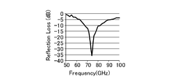
- the radio wave absorber film was manufactured and evaluated in the same manner as in Example 1. The evaluation results are shown in Table 1. Further, FIG. 2 shows the amount of reflection attenuation of the radio wave absorber film of Example 2 in the range of 50 to 100 GHz.
- Example 3 Change the binder resin to an aromatic ester-urethane copolymer (manufactured by Toyo Boseki Co., Ltd., consisting of Byron UR-1400, glass transition temperature 83 ° C., weight average molecular weight 40,000, resin 5 parts by mass and methyl ethyl ketone 15 parts by mass).
- the radio wave absorber film was manufactured and evaluated in the same manner as in Example 1. The evaluation results are shown in Table 1. Further, FIG. 3 shows the amount of reflection attenuation of the radio wave absorber film of Example 3 in the range of 50 to 100 GHz.
- Example 4 Changed the binder resin to an aromatic ester-urethane copolymer (manufactured by Toyo Boseki Co., Ltd., consisting of Byron UR-8700, glass transition temperature -22 ° C, weight average molecular weight 32000, resin 5 parts by mass and methyl ethyl ketone 15 parts by mass).
- the radio wave absorber film was produced and evaluated in the same manner as in Example 1. The evaluation results are shown in Table 1. Further, FIG. 4 shows the amount of reflection attenuation of the radio wave absorber film of Example 4 in the range of 50 to 100 GHz.
- Ethyl cellulose (manufactured by Nikkei Seisei Co., Ltd.) was used as the binder resin solution.
- the PET film (thickness 125 ⁇ m) was coated with an applicator using the above-mentioned paste for forming a radio wave absorbing layer. Then, the coating film was dried under the conditions of 90 ° C. for 10 minutes and 130 ° C. for 10 minutes to form a radio wave absorbing layer having a thickness of 35 ⁇ m to obtain a radio wave absorber film.
- the radio wave absorber film obtained immediately after drying was cut into a square shape of 5 cm square to prepare a test piece for evaluation. The evaluation results are shown in Table 1. Further, FIG. 5 shows the amount of reflection attenuation of the radio wave absorber film of Comparative Example 1 in the range of 50 to 100 GHz.
- the radio wave absorber film of the embodiment provided with the radio wave absorbing layer formed by using the aromatic ester-urethane copolymer as the binder resin has a radio wave absorbing layer of 50 to 100 GHz even though the radio wave absorbing layer is thin. It can be seen that the amount of radio wave absorption in the frequency range of is large.
- the radio wave absorber film of the comparative example including the radio wave absorbing layer formed by using ethyl cell roll as the binder resin has a radio wave absorbing layer in the frequency range of 50 to 100 GHz, although the radio wave absorbing layer is thicker than that of the embodiment. It can be seen that the amount of absorption is inferior to that of the radio wave absorber film of the example.
- the radio wave absorber film of the example in which the aromatic ester-urethane copolymer is used as the binder resin cracks are less likely to occur at the time of cutting, and in particular, the aromatic ester-urethane co-weight exhibiting Tg of 0 ° C. or lower.
- the radio wave absorber films of Examples 1 and 4 in which the coalesced material was used as the binder resin cracks were unlikely to occur even when bent 180 °.
- the radio wave absorber film of the comparative example provided with the radio wave absorbing layer formed by using ethyl cell roll as the binder resin had cracks at the time of bending and cutting.
Landscapes
- Engineering & Computer Science (AREA)
- Power Engineering (AREA)
- Microelectronics & Electronic Packaging (AREA)
- Life Sciences & Earth Sciences (AREA)
- Wood Science & Technology (AREA)
- Physics & Mathematics (AREA)
- Electromagnetism (AREA)
- Shielding Devices Or Components To Electric Or Magnetic Fields (AREA)
- Laminated Bodies (AREA)
- Hard Magnetic Materials (AREA)
- Soft Magnetic Materials (AREA)
Priority Applications (5)
| Application Number | Priority Date | Filing Date | Title |
|---|---|---|---|
| KR1020227005479A KR20220047781A (ko) | 2019-08-19 | 2020-07-30 | 전파 흡수체 필름, 및 그 제조 방법 |
| CN202080057040.3A CN114223042A (zh) | 2019-08-19 | 2020-07-30 | 电波吸收体膜及其制造方法 |
| JP2021540702A JP7576800B2 (ja) | 2019-08-19 | 2020-07-30 | 電波吸収体フィルム、及びその製造方法 |
| EP20855143.2A EP4020506A4 (en) | 2019-08-19 | 2020-07-30 | RADIO WAVE ABSORBER FILM AND PRODUCTION METHOD THEREFOR |
| US17/635,627 US20220288633A1 (en) | 2019-08-19 | 2020-07-30 | Radio wave absorber film and method for producing same |
Applications Claiming Priority (2)
| Application Number | Priority Date | Filing Date | Title |
|---|---|---|---|
| JP2019-150011 | 2019-08-19 | ||
| JP2019150011 | 2019-08-19 |
Publications (1)
| Publication Number | Publication Date |
|---|---|
| WO2021033517A1 true WO2021033517A1 (ja) | 2021-02-25 |
Family
ID=74661063
Family Applications (1)
| Application Number | Title | Priority Date | Filing Date |
|---|---|---|---|
| PCT/JP2020/029362 Ceased WO2021033517A1 (ja) | 2019-08-19 | 2020-07-30 | 電波吸収体フィルム、及びその製造方法 |
Country Status (6)
| Country | Link |
|---|---|
| US (1) | US20220288633A1 (https=) |
| EP (1) | EP4020506A4 (https=) |
| JP (1) | JP7576800B2 (https=) |
| KR (1) | KR20220047781A (https=) |
| CN (1) | CN114223042A (https=) |
| WO (1) | WO2021033517A1 (https=) |
Families Citing this family (1)
| Publication number | Priority date | Publication date | Assignee | Title |
|---|---|---|---|---|
| KR102828165B1 (ko) * | 2023-09-08 | 2025-07-03 | (주)이녹스첨단소재 | 전자파 흡수체 |
Citations (8)
| Publication number | Priority date | Publication date | Assignee | Title |
|---|---|---|---|---|
| JPH01106317A (ja) * | 1987-10-19 | 1989-04-24 | Konica Corp | 磁気記録媒体 |
| JP2003229694A (ja) * | 2002-02-05 | 2003-08-15 | Sony Corp | 電磁波吸収体およびその製造方法 |
| WO2006059771A1 (ja) * | 2004-12-03 | 2006-06-08 | Nitta Corporation | 電磁干渉抑制体、アンテナ装置、及び電子情報伝達装置 |
| JP2008174405A (ja) | 2007-01-16 | 2008-07-31 | Univ Of Tokyo | ε−Fe2O3結晶の製法 |
| JP2008277726A (ja) | 2006-09-01 | 2008-11-13 | Univ Of Tokyo | 電波吸収材料用の磁性結晶および電波吸収体 |
| JP2009060060A (ja) | 2007-09-03 | 2009-03-19 | Osaka Industrial Promotion Organization | 電磁波吸収シート |
| JP2017184106A (ja) * | 2016-03-31 | 2017-10-05 | 国立大学法人 東京大学 | 高周波アンテナ素子、及び高周波アンテナモジュール |
| WO2018235952A1 (ja) * | 2017-06-23 | 2018-12-27 | マクセルホールディングス株式会社 | 電磁波吸収性組成物、電磁波吸収シート |
Family Cites Families (5)
| Publication number | Priority date | Publication date | Assignee | Title |
|---|---|---|---|---|
| JP5557992B2 (ja) * | 2008-09-02 | 2014-07-23 | 国立大学法人北海道大学 | カーボンナノチューブが付着した導電性繊維、導電性糸、繊維構造体およびそれらの製造方法 |
| JP5621642B2 (ja) * | 2011-02-09 | 2014-11-12 | 東洋紡株式会社 | 易接着性ポリエステルフィルム |
| EP2929527B1 (en) * | 2011-12-06 | 2020-11-18 | E- Vision Smart Optics, Inc. | Systems, devices, and/or methods for providing images |
| TW201601915A (zh) * | 2014-07-07 | 2016-01-16 | 聯茂電子股份有限公司 | 電磁波干擾遮蔽薄膜 |
| RU2598090C1 (ru) * | 2015-03-20 | 2016-09-20 | Российская Федерация, от имени которой выступает Государственная корпорация по атомной энергии "Росатом" | Лакокрасочная радиопоглощающая композиция |
-
2020
- 2020-07-30 WO PCT/JP2020/029362 patent/WO2021033517A1/ja not_active Ceased
- 2020-07-30 CN CN202080057040.3A patent/CN114223042A/zh active Pending
- 2020-07-30 US US17/635,627 patent/US20220288633A1/en active Pending
- 2020-07-30 KR KR1020227005479A patent/KR20220047781A/ko active Pending
- 2020-07-30 JP JP2021540702A patent/JP7576800B2/ja active Active
- 2020-07-30 EP EP20855143.2A patent/EP4020506A4/en active Pending
Patent Citations (8)
| Publication number | Priority date | Publication date | Assignee | Title |
|---|---|---|---|---|
| JPH01106317A (ja) * | 1987-10-19 | 1989-04-24 | Konica Corp | 磁気記録媒体 |
| JP2003229694A (ja) * | 2002-02-05 | 2003-08-15 | Sony Corp | 電磁波吸収体およびその製造方法 |
| WO2006059771A1 (ja) * | 2004-12-03 | 2006-06-08 | Nitta Corporation | 電磁干渉抑制体、アンテナ装置、及び電子情報伝達装置 |
| JP2008277726A (ja) | 2006-09-01 | 2008-11-13 | Univ Of Tokyo | 電波吸収材料用の磁性結晶および電波吸収体 |
| JP2008174405A (ja) | 2007-01-16 | 2008-07-31 | Univ Of Tokyo | ε−Fe2O3結晶の製法 |
| JP2009060060A (ja) | 2007-09-03 | 2009-03-19 | Osaka Industrial Promotion Organization | 電磁波吸収シート |
| JP2017184106A (ja) * | 2016-03-31 | 2017-10-05 | 国立大学法人 東京大学 | 高周波アンテナ素子、及び高周波アンテナモジュール |
| WO2018235952A1 (ja) * | 2017-06-23 | 2018-12-27 | マクセルホールディングス株式会社 | 電磁波吸収性組成物、電磁波吸収シート |
Non-Patent Citations (8)
| Title |
|---|
| A.NAMAIM.YOSHIKIYOK.YAMADAS.SAKURAIT.GOTOT.YOSHIDAT.MIYA ZAKIM.NAKAJIMAT.SUEMOTOH.TOKORO, NATURE COMMUNICATIONS, vol. 3, no. 1035, 2012, pages 1 - 6 |
| A.NAMAIS.SAKURAIM.NAKAJIMAT.SUEMOTOK.MATSUMOTOM.GOTOS.SA SAKIS.OHKOSHI, J.AM.CHEM.SOC., vol. 131, 2009, pages 1170 - 1173 |
| ASUKA NAMAISHUNSUKE SAKURAIMAKOTO NAKAJIMATOHRU SUEMOTOKAZUYUKI MATSUMOTOMASAHIRO GOTOSHINYA SASAKISHINICHI OHKOSHI, JOURNAL OF THE AMERICAN CHEMICAL SOCIETY, vol. 131, 2009, pages 1170 - 1173 |
| JIAN JINSHINICHI OHKOSHIKAZUHITO HASHIMOTO, ADVANCED MATERIALS, vol. 16, no. 1, 2004, pages 48 - 51 |
| S.OHKOSHI,S.KUROKI,S.SAKURAI,K.MATSUMOTO,K.SATO, AND S.SASAKI, ANGEW.CHEM.INT.ED., vol. 46, 2007, pages 8392 - 8395 |
| See also references of EP4020506A4 |
| SHIN-ICHI OHKOSHISHUNSUKE SAKURAIJIAN JINKAZUHITO HASHIMOTO, JOURNAL OF APPLIED PHYSICS, vol. 97, 2005, pages 10K312 |
| SHUNSUKE SAKURAIJIAN JINKAZUHITO HASHIMOTOSHINICHI OHKOSHI, JOURNAL OF THE PHYSICAL SOCIETY OF JAPAN, vol. 74, no. 7, July 2005 (2005-07-01), pages 1946 - 1949 |
Also Published As
| Publication number | Publication date |
|---|---|
| JP7576800B2 (ja) | 2024-11-01 |
| CN114223042A (zh) | 2022-03-22 |
| EP4020506A1 (en) | 2022-06-29 |
| US20220288633A1 (en) | 2022-09-15 |
| EP4020506A4 (en) | 2023-09-13 |
| JPWO2021033517A1 (https=) | 2021-02-25 |
| KR20220047781A (ko) | 2022-04-19 |
Similar Documents
| Publication | Publication Date | Title |
|---|---|---|
| JP7712637B2 (ja) | 電磁波吸収体、及び電磁波吸収体形成用ペースト | |
| JP6616653B2 (ja) | 電磁波吸収体及び膜形成用ペースト | |
| JP7464944B2 (ja) | 電波吸収積層フィルム、その製造方法、及びそれを含む素子 | |
| KR102271402B1 (ko) | 고주파 안테나 소자, 및 고주파 안테나 모듈 | |
| EP3029771B1 (en) | Electromagnetic wave absorber and film forming paste | |
| EP2447965B1 (en) | Process for production of magnetic thin film | |
| Rusly et al. | Microwave absorption properties of single-and double-layer coatings based on strontium hexaferrite and graphite nanocomposite | |
| JP7273953B2 (ja) | 電波吸収体 | |
| EP3643752A1 (en) | Electromagnetic wave absorbing composition and electromagnetic wave absorption sheet | |
| Li et al. | Microwave absorption characteristic of a double-layer X-band absorber based on MWCNTs/La0. 6Sr0. 4Mn0. 5Fe0. 5O4 coated with PEDOT polymer | |
| JP2022041986A (ja) | 赤外線吸収粒子の製造方法 | |
| WO2020230708A1 (ja) | 電波吸収体 | |
| JP7576800B2 (ja) | 電波吸収体フィルム、及びその製造方法 | |
| Liu et al. | Tunable electromagnetic properties in barium hexagonal ferrites with dual‐ion substitution | |
| Jayaseelan et al. | The impacts of Mn ion incorporation on the structural, optical, and magnetic properties of hematite NPs | |
| WO2024203732A1 (ja) | 電磁波吸収体、及び電磁波吸収体形成用ペースト | |
| WO2025220476A1 (ja) | 電磁波吸収体、及び電磁波吸収体形成用ペースト | |
| Roohani et al. | Magnetic and structural properties of SrFe12− xCrxO19 (x= 0, 0.25, 0.5, 0.75, 1) hexaferrite powders obtained by sol–gel auto-combustion method | |
| TW202605858A (zh) | 電磁波吸收體及電磁波吸收體形成用糊料 | |
| Ma et al. | Ca2+-Cu2+-Sn4+ co-doped M-type hexagonal barium ferrite for enhanced microwave absorption efficiency |
Legal Events
| Date | Code | Title | Description |
|---|---|---|---|
| 121 | Ep: the epo has been informed by wipo that ep was designated in this application |
Ref document number: 20855143 Country of ref document: EP Kind code of ref document: A1 |
|
| ENP | Entry into the national phase |
Ref document number: 2021540702 Country of ref document: JP Kind code of ref document: A |
|
| NENP | Non-entry into the national phase |
Ref country code: DE |
|
| ENP | Entry into the national phase |
Ref document number: 2020855143 Country of ref document: EP Effective date: 20220321 |
|
| WWR | Wipo information: refused in national office |
Ref document number: 1020227005479 Country of ref document: KR |
|
| WWC | Wipo information: continuation of processing after refusal or withdrawal |
Ref document number: 1020227005479 Country of ref document: KR |