WO2021024706A1 - エンコーダシステム、モータシステム及びロボット - Google Patents
エンコーダシステム、モータシステム及びロボット Download PDFInfo
- Publication number
- WO2021024706A1 WO2021024706A1 PCT/JP2020/027243 JP2020027243W WO2021024706A1 WO 2021024706 A1 WO2021024706 A1 WO 2021024706A1 JP 2020027243 W JP2020027243 W JP 2020027243W WO 2021024706 A1 WO2021024706 A1 WO 2021024706A1
- Authority
- WO
- WIPO (PCT)
- Prior art keywords
- power supply
- encoder
- voltage
- wiring
- supply wiring
- Prior art date
- Legal status (The legal status is an assumption and is not a legal conclusion. Google has not performed a legal analysis and makes no representation as to the accuracy of the status listed.)
- Ceased
Links
Images



Classifications
-
- G—PHYSICS
- G01—MEASURING; TESTING
- G01D—MEASURING NOT SPECIALLY ADAPTED FOR A SPECIFIC VARIABLE; ARRANGEMENTS FOR MEASURING TWO OR MORE VARIABLES NOT COVERED IN A SINGLE OTHER SUBCLASS; TARIFF METERING APPARATUS; MEASURING OR TESTING NOT OTHERWISE PROVIDED FOR
- G01D5/00—Mechanical means for transferring the output of a sensing member; Means for converting the output of a sensing member to another variable where the form or nature of the sensing member does not constrain the means for converting; Transducers not specially adapted for a specific variable
- G01D5/12—Mechanical means for transferring the output of a sensing member; Means for converting the output of a sensing member to another variable where the form or nature of the sensing member does not constrain the means for converting; Transducers not specially adapted for a specific variable using electric or magnetic means
- G01D5/14—Mechanical means for transferring the output of a sensing member; Means for converting the output of a sensing member to another variable where the form or nature of the sensing member does not constrain the means for converting; Transducers not specially adapted for a specific variable using electric or magnetic means influencing the magnitude of a current or voltage
-
- B—PERFORMING OPERATIONS; TRANSPORTING
- B25—HAND TOOLS; PORTABLE POWER-DRIVEN TOOLS; MANIPULATORS
- B25J—MANIPULATORS; CHAMBERS PROVIDED WITH MANIPULATION DEVICES
- B25J13/00—Controls for manipulators
-
- B—PERFORMING OPERATIONS; TRANSPORTING
- B25—HAND TOOLS; PORTABLE POWER-DRIVEN TOOLS; MANIPULATORS
- B25J—MANIPULATORS; CHAMBERS PROVIDED WITH MANIPULATION DEVICES
- B25J19/00—Accessories fitted to manipulators, e.g. for monitoring, for viewing; Safety devices combined with or specially adapted for use in connection with manipulators
- B25J19/02—Sensing devices
-
- B—PERFORMING OPERATIONS; TRANSPORTING
- B25—HAND TOOLS; PORTABLE POWER-DRIVEN TOOLS; MANIPULATORS
- B25J—MANIPULATORS; CHAMBERS PROVIDED WITH MANIPULATION DEVICES
- B25J9/00—Program-controlled manipulators
- B25J9/10—Program-controlled manipulators characterised by positioning means for manipulator elements
- B25J9/12—Program-controlled manipulators characterised by positioning means for manipulator elements electric
-
- G—PHYSICS
- G01—MEASURING; TESTING
- G01D—MEASURING NOT SPECIALLY ADAPTED FOR A SPECIFIC VARIABLE; ARRANGEMENTS FOR MEASURING TWO OR MORE VARIABLES NOT COVERED IN A SINGLE OTHER SUBCLASS; TARIFF METERING APPARATUS; MEASURING OR TESTING NOT OTHERWISE PROVIDED FOR
- G01D5/00—Mechanical means for transferring the output of a sensing member; Means for converting the output of a sensing member to another variable where the form or nature of the sensing member does not constrain the means for converting; Transducers not specially adapted for a specific variable
- G01D5/12—Mechanical means for transferring the output of a sensing member; Means for converting the output of a sensing member to another variable where the form or nature of the sensing member does not constrain the means for converting; Transducers not specially adapted for a specific variable using electric or magnetic means
- G01D5/244—Mechanical means for transferring the output of a sensing member; Means for converting the output of a sensing member to another variable where the form or nature of the sensing member does not constrain the means for converting; Transducers not specially adapted for a specific variable using electric or magnetic means influencing characteristics of pulses or pulse trains; generating pulses or pulse trains
-
- H—ELECTRICITY
- H02—GENERATION; CONVERSION OR DISTRIBUTION OF ELECTRIC POWER
- H02P—CONTROL OR REGULATION OF ELECTRIC MOTORS, ELECTRIC GENERATORS OR DYNAMO-ELECTRIC CONVERTERS; CONTROLLING TRANSFORMERS, REACTORS OR CHOKE COILS
- H02P5/00—Arrangements specially adapted for regulating or controlling the speed or torque of two or more electric motors
-
- H—ELECTRICITY
- H02—GENERATION; CONVERSION OR DISTRIBUTION OF ELECTRIC POWER
- H02P—CONTROL OR REGULATION OF ELECTRIC MOTORS, ELECTRIC GENERATORS OR DYNAMO-ELECTRIC CONVERTERS; CONTROLLING TRANSFORMERS, REACTORS OR CHOKE COILS
- H02P6/00—Arrangements for controlling synchronous motors or other dynamo-electric motors using electronic commutation dependent on the rotor position; Electronic commutators therefor
- H02P6/14—Electronic commutators
- H02P6/16—Circuit arrangements for detecting position
-
- H—ELECTRICITY
- H02—GENERATION; CONVERSION OR DISTRIBUTION OF ELECTRIC POWER
- H02P—CONTROL OR REGULATION OF ELECTRIC MOTORS, ELECTRIC GENERATORS OR DYNAMO-ELECTRIC CONVERTERS; CONTROLLING TRANSFORMERS, REACTORS OR CHOKE COILS
- H02P2203/00—Indexing scheme relating to controlling arrangements characterised by the means for detecting the position of the rotor
- H02P2203/03—Determination of the rotor position, e.g. initial rotor position, during standstill or low speed operation
Definitions
- the present invention relates to an encoder system including an encoder used for position detection in a robot driven by a motor, and a motor system and a robot including the encoder system.
- a robot composed of a manipulator and a controller is driven by a motor provided for each axis in the manipulator, and the motor of each axis is controlled by the controller based on the position of the axis.
- An encoder is used to detect the position of each axis. If the encoder does not operate normally, the manipulator provided with the encoder cannot operate normally.
- the encoder is connected to the rotation axis of the motor of each axis of the manipulator and detects the rotation position of the motor.
- the encoder includes an electronic circuit or the like inside, and a power supply voltage is supplied to output a signal indicating an axis position or the like to a robot control device or the like.
- the power supply wiring which is the wiring for supplying power
- the signal wiring for transmitting signals are connected to the encoder.
- a manipulator is provided with a plurality of axes and a plurality of encoders are provided, but it is common to supply a power supply voltage to the plurality of encoders in a form of branching from a common wiring.
- An absolute value encoder is generally used as the encoder provided in the manipulator. The absolute value encoder needs to be able to hold data by shifting to backup mode when the supply of power supply voltage from the outside is stopped, and to perform minimum operations such as storing changes in the rotation position during that time. ..
- Some robots in recent years such as robots that transport glass substrates used in the manufacture of liquid crystal display panels, have a large manipulator part and a long movement distance on the axis. Since the position of the encoder changes in the three-dimensional space of the encoder as the manipulator operates, that is, the encoder also moves, the wiring cable provided in the manipulator and connected to the encoder also moves and is bent or twisted. Bending or twisting of wiring is called deformation of wiring. Deformation of the wiring can result in short circuits and ground faults in the wiring within the cable.
- the signal wiring of the wiring connected to the encoder If a failure occurs in the signal wiring of the wiring connected to the encoder, the signal wiring is provided for each axis to transmit position data, so even if a failure occurs, the failure will also be a communication error for each axis. It will be detected as, and the defective axis can be easily identified.
- the power supply of all encoders becomes abnormal at the same time from the common wiring, and the information of the axis in which the power supply error occurred indicates which axis power supply wiring has failed. It becomes difficult to identify based on. For this reason, it becomes necessary to visually inspect all of the power supply wiring provided in the manipulator, and in the case of a large manipulator, it takes a lot of time to identify the faulty part.
- Patent Document 1 describes an abnormality detection unit that detects an abnormality based on state information related to the state of an encoder or a motor, and state information when an abnormality is detected.
- an encoder including a cause analysis unit that analyzes the cause of an abnormality based on the above, and a non-volatile memory control unit that stores the analysis result by the cause analysis unit in a non-volatile memory.
- Patent Document 2 provides an auxiliary power supply for each encoder and assists when the value of the power supply voltage supplied from the controller side is equal to or less than the threshold value.
- Patent Documents 1 and 2 cannot be used to identify a faulty part in the power supply wiring connected to the encoder.
- Patent Document 3 describes that when the power supply voltage is supplied from the common power supply to a plurality of external devices, the power supply voltage is supplied from the common power supply.
- a connection / disconnection circuit is provided for each of the power lines that branch off for each external device, and when a voltage drop in the common power supply is detected, the power supply lines are disconnected from the common power supply in order for each power supply line. It discloses that it detects which external device the power line has failed.
- Patent Document 3 can detect which external device the power line has failed if the failure is a complete ground fault or short circuit, but is applied to the detection of the failure in the power wiring of the encoder. If this is the case, it is insufficient to isolate the failure in the power supply wiring and the failure in the signal wiring or to find a sign before the failure.
- An object of the present invention is to provide an encoder system capable of easily identifying a faulty part in power supply wiring to an encoder, and a motor system and a robot provided with such an encoder system.
- the encoder system of the present invention includes a plurality of encoders, an encoder power supply circuit that generates a power supply voltage, individual power supply wiring provided for each encoder to supply a power supply voltage, and one end connected to the encoder, and individual power supply wiring.
- a switch is provided on the other end side of the individual power supply wiring to switch between connection and disconnection to the encoder power supply circuit, and each individual power supply wiring is provided on the other end side of the individual power supply wiring on the encoder side of the switch. It also has a first voltage detection circuit.
- individual power supply wiring can be independently connected to or disconnected from the encoder power supply circuit by a switch, and the voltage can be measured for each individual power supply wiring.
- a failure such as a ground fault or short circuit occurs in the wiring, it is possible to quickly determine which individual power supply wiring is the failure, and it is also possible to isolate and determine from the failure in the signal wiring, etc., and identify the defective part in a short time. You will be able to do it in time.
- the encoder system of the present invention includes a second voltage detection circuit in which the first voltage detection circuit outputs a voltage value and the encoder detects the supplied power supply voltage and outputs the voltage value. Is preferable. According to this configuration, the voltage drop and wiring impedance in the individual power supply wiring can be calculated from the difference between the voltage value detected by the first voltage detection circuit and the voltage value detected by the second voltage detection circuit, and the individual power supply can be calculated. It becomes easier to detect abnormalities in wiring and signs before abnormalities. If the encoder has a function to shift to the backup mode by detecting a voltage drop, the shift to the backup mode in the event of an abnormality can be easily performed.
- a calculation means for calculating the difference between the voltage value detected by the first voltage detection circuit and the voltage value detected by the second voltage detection circuit is further provided. May be good. By calculating the difference in the calculation means, the voltage drop and the wiring impedance can be automatically calculated, and it becomes easier to find an abnormality or a sign before the abnormality.
- the calculation means may output a power supply control signal corresponding to the difference to the encoder power supply circuit. By transmitting the power supply control signal to the encoder power supply circuit, it is possible to maintain the power supply voltage supplied to the encoder at an appropriate value even if the voltage drop or the wiring impedance changes.
- a plurality of encoders may be classified into a plurality of systems according to the length of individual power supply wiring, and an encoder power supply circuit may be provided for each system. Since the voltage drop amount differs depending on the length of the individual power supply wiring, it is classified into multiple systems based on the length of the individual power supply wiring, and an encoder power supply circuit is provided for each system to anticipate the voltage drop amount.
- the output voltage of the power supply circuit can be set, and the value of the power supply voltage actually supplied to each encoder can be brought closer to an appropriate value.
- the motor system of the present invention is a motor system including a plurality of motors, the encoder system of the present invention is provided, and an encoder of the encoder system is provided for each motor. According to the motor system of the present invention, by providing the encoder system of the present invention, when a failure such as a ground fault or a short circuit occurs in the individual power supply wiring provided for each encoder, it is possible to quickly determine which individual power supply wiring is the failure. It is possible to identify the defective part in a short time.
- the robot of the present invention is a robot having a manipulator including a plurality of motors and a controller for controlling the manipulators, and is provided with the encoder system of the present invention, and an encoder of the encoder system is provided for each motor. According to the robot of the present invention, when a failure such as a ground fault or a short circuit occurs in the individual power supply wiring provided for each encoder, it is possible to quickly determine which individual power supply wiring is the failure, and the defective part can be identified in a short time. Can be done with.
- the section between the first voltage detection circuit and the encoder for each individual power supply wiring includes a section in which the individual power supply wiring is deformed as the manipulator moves. ..
- the section that is deformed due to the movement of the manipulator should be included in the section between the switch and the first voltage detection circuit provided on the other end side and the encoder on the one end side.
- the switch and the first voltage detection circuit can be arranged in the controller. By arranging it on the controller, the present invention can be applied to a conventional robot without modifying the manipulator side.
- the switch and the first voltage detection circuit can be arranged in the manipulator. If it is arranged in the manipulator, only one power supply wiring related to the encoder needs to be prepared between the controller and the manipulator, so that the wiring can be easily routed.
- FIG. 1 shows a robot according to an embodiment of the present invention.
- This robot includes a controller 10 and a manipulator 50, and the manipulator 50 includes a plurality of axes.
- the manipulator 50 is provided with a motor 51 and an encoder 52 mechanically connected to the motor 51 of the shaft for each shaft.
- four sets of the motor 51 and the encoder 52 are drawn assuming that the number of axes is 4, but the number of axes in the manipulator 50 may be 5 or more.
- the controller 10 includes a driver circuit 11 that drives the motor 51 of each axis in the manipulator 50, an encoder power circuit 12 that generates a power supply voltage supplied to the encoder 52 of each axis, and a motor position from the encoder 52 of each axis. It is provided with an encoder receiving circuit 13 that receives a signal indicating the above, and a control unit 14 that is configured by a microprocessor or the like and executes an operation or the like necessary for controlling the entire robot. In the figure, for the sake of explanation, the wiring related to the control unit 14 is shown by a broken line.
- the motor 51 of each shaft is connected to the driver circuit 11 by a motor wiring 53 provided for each motor 51, and is driven independently for each shaft by the driver circuit 11.
- an individual power supply wiring 54 is provided for each encoder 52 at least in the manipulator 50.
- the individual power supply wiring 54 also extends into the controller 10.
- the power supply voltage is output from the encoder power supply circuit 12 via the common power supply wiring 21.
- individual power supply wirings 54 for each shaft are connected to the common power supply wiring 21 via a switch 22 for each shaft.
- the controller 10 is provided with a voltage detection circuit 23 for each individual power supply wiring 54, which is connected to the corresponding individual power supply wiring 54 to detect the voltage.
- the position where the voltage detection circuit 23 is provided in the individual power supply wiring 54 is close to the switch 22, but is closer to the encoder 52 than the switch 22.
- one end of the individual power supply wiring 54 is connected to the encoder 52, and the switch 22 and the voltage detection circuit 23 are provided on the other end side.
- the power supply voltage for the encoder 52 of each axis is supplied from the common power supply wiring 21 commonly provided in the encoder 52 via the switch 22 and the individual power supply wiring 54 provided for each encoder 52. It will be.
- the switch 22 realizes connection and disconnection to the encoder power supply circuit 12 for each encoder 52.
- the signal from the encoder 52 of each axis is input to the encoder receiving circuit 13 via the signal wiring 55 provided for each encoder 52.
- the controller 10 is also provided with a disconnection detection circuit 15 that detects a disconnection of the signal wiring 55 by detecting a signal voltage or the like in each signal wiring 55.
- the control unit 14 uses the driver circuit 11 via the driver circuit 11 so that the position of the manipulator 50 becomes the position specified by the position command based on, for example, the position command input from the outside and the position data input from each encoder 52.
- the control for driving the motor 51 of the above is executed, and further, the on (conduction) / off (disconnection) of each switch 22 and the encoder power supply circuit 12 are controlled, and the input from the disconnection detection circuit 15 and each voltage detection circuit 23 are used. Based on the detected value of, the presence or absence of a failure and the location of the failure are identified.
- the switch 22 is composed of, for example, a mechanical relay or a semiconductor switch.
- the robot of this embodiment is, for example, a robot for transporting a glass substrate used for manufacturing a liquid crystal display panel, etc., and is provided with a large manipulator 50 and has a long moving distance of the manipulator 50. Therefore, the lengths of the motor wiring 53, the individual power supply wiring 54, and the signal wiring 55 in the manipulator 50 are, for example, several tens of meters. As the manipulator 50 operates and moves, the motor wiring 53, the individual power supply wiring 54, and the signal wiring 55 also move together with the manipulator 50, and as a result, they are bent or twisted, that is, deformed and subjected to various stresses. It will be. Such stress can also cause ground faults, short circuits, and disconnections in wiring.
- the common power supply wiring 21 from the encoder power supply circuit 12 extends from the controller 10 to the manipulator 50, and the individual power supply wiring 54 from each encoder 52 is connected to the end of the common power supply wiring 21.
- the output of the encoder power supply circuit 12 is cut off due to an overcurrent or the output voltage drops, and the power supply to all the encoders 52 is stopped. To do.
- each encoder 52 has a function of detecting an abnormality in the power supply voltage, it is possible to identify which encoder 52 the individual power supply wiring 54 connected to has a failure depending on the signal from the encoder 52. I can't.
- all the individual power supply wirings 54 in the manipulator 50 must be visually inspected.
- the manipulator 50 becomes large and the manipulator 50 itself is arranged in a clean room or a reduced pressure environment. Therefore, inspect all the individual power supply wirings 54 in the manipulator 50. It takes a lot of time to recover the robot from the failure.
- the individual power supply wiring 54 connected to each encoder 52 is slightly closer to the encoder 52 than the position connected to the common power supply wiring 21 connected to the encoder power supply circuit 12.
- a switch 22 is provided at the position.
- the switch 22 can be individually turned on / off by the control unit 14 for each individual power supply wiring 54, that is, for each encoder 52. Therefore, immediately after the power of the controller 10 is turned on, the switch 22 for each encoder 52 is individually turned on and then turned off for each encoder 52 in order. At this time, if the signal from the encoder 52 corresponding to the turned-on switch 22 can be correctly received in the encoder receiving circuit 13, the individual power supply wiring 54 and the signal wiring 55 corresponding to the encoder 52 are both normal.
- control unit 14 turns on the switches 22 one by one in order to determine which encoder 52 the wiring connected to has a failure, and the wiring in which the failure has occurred is an individual power supply wiring. It becomes possible to easily identify whether it is 54 or the signal wiring 55, and even if the wiring must be visually inspected, the inspection points can be limited, which is necessary for identifying the failure location and recovering from the failure. It is possible to save a lot of time.
- the voltage detection circuit 23 may be composed of a voltage comparator circuit that only determines whether the input voltage is normal or not. However, it is preferable that the voltage detection circuit 23 outputs the measured voltage as a voltage value rather than outputting a binary signal indicating good or bad.
- the voltage value referred to here may be an analog value, or may be a digital value represented as multi-valued data by an analog / digital (A / D) conversion function or the like.
- the voltage detection circuit 23 is a circuit that detects a voltage value that is analog value or multi-value data, and the encoder 52 is also provided with a circuit that detects the supplied power supply voltage, the voltage detection circuit 23 From the detected voltage value and the voltage value detected by the encoder 52, the amount of voltage drop in the individual power supply wiring 54 can be obtained. If the manipulator 50 is large, the individual power supply wiring 54 is also long, and the voltage drop at the power supply voltage supplied by the individual power supply wiring 54 cannot be ignored. Since the current consumption of the encoder 52 is known and does not fluctuate significantly, it is possible to calculate the wiring impedance of the individual power supply wiring 54 from the voltage drop amount of the individual power supply wiring 54 and the current consumption of the encoder 52 for maintenance. And design margins can be easily confirmed.
- the power supply voltage actually measured by the encoder 52 is fed back to the control unit 14, and the control unit 14 controls the encoder power supply circuit 12, so that the encoder 52 actually operates regardless of the amount of voltage drop in the individual power supply wiring 54.
- the supplied power supply voltage value can be set as an appropriate value.
- the control unit 14 obtains a difference between the voltage value detected by the voltage detection circuit 23 and the voltage value detected by the encoder 52, and outputs a voltage control signal corresponding to this difference to the encoder power supply circuit 12.
- the lengths of the motor wiring 53, the individual power supply wiring 54, and the signal wiring 55 may differ greatly depending on which axis of the manipulator 50 the motor 51 or encoder 52 belongs to. If the length of the individual power supply wiring 54 is different, the amount of voltage drop in the individual power supply wiring 54 will be different, and the power supply voltage actually supplied to the encoder 52 will also be different. When the amount of voltage drop in the individual power supply wiring 54 is different, the power supply voltage actually supplied is different for each encoder 52 when the power supply voltage is supplied to the plurality of encoders 52 from the same encoder power supply circuit 12, and is described above.
- the robot of another embodiment of the present invention shown in FIG. 3 is similar to the robot shown in FIG. 1, but the power supply voltage actually supplied to the encoder 52 varies depending on the length of the individual power supply wiring 54.
- the plurality of encoders 52 are classified into several systems according to the length of the individual power supply wirings 54, and the encoder power supply circuits 12 and 16 are provided for each system. In the illustrated one, two encoder power supply circuits 12 and 16 are provided, and among the four encoders 52, the encoder power supply circuit 12 starts with respect to the two encoders 52 in which the length of the individual power supply wiring 54 is relatively short.
- the power supply voltage is supplied, and the power supply voltage is supplied from the encoder power supply circuit 16 to the two encoders 52 having relatively long individual power supply wirings 54.
- the output voltages of the encoder power supply circuits 12 and 16 can be adjusted by control from the control unit 14, respectively. Basically, these output voltages take into account the amount of voltage drop in the individual power supply wiring 54. It has become. This makes it possible to drive each encoder 52 with a power supply voltage closer to an appropriate value regardless of the difference in the length of the individual power supply wiring 54.
- a common power supply wiring 21 is provided for each of the encoder power supply circuits 12 and 16, a plurality of individual power supply wirings 54 are branched from each common power supply wiring 21, and a switch 22 and a voltage detection circuit 23 are provided for each individual power supply wiring 54. This is the same as that shown in FIG.
- the feedback control of the output voltage of the encoder power supply circuits 12 and 16 can be independently performed based on the power supply voltage actually supplied to each encoder 52. Despite the difference in the amount of voltage drop, the variation in the voltage actually supplied to each encoder 52 in the four encoders 52 becomes small, and the power supply voltage actually supplied to these encoders 52 is brought closer to the appropriate value. Will be possible.
- the switch 22 and the voltage detection circuit 23 are provided in the controller 10, but the switch 22 and the voltage detection circuit 23 can also be provided in the manipulator 50.
- the robot of still another embodiment shown in FIG. 4 extends the common power supply wiring 21 to the manipulator 50, and at the same time, the branch point from the common power supply wiring 21 to the individual power supply wiring 54, the switch 22, and the voltage.
- the detection circuit 23 is provided in the manipulator 50, and a control unit 60 for controlling the switch 22 and receiving the detection result from the voltage detection circuit 23 is provided.
- the control unit 60 controls the robot in cooperation with the control unit 14 provided in the controller 10.
- the switch 22 and the voltage detection circuit 23 are provided with a manipulator 50 in the individual power supply wiring 54. It is preferable to provide the controller 10 closer to the portion that moves with the movement of the controller 10. Specifically, it is preferable that the individual power supply wiring 54 is branched from the common power supply wiring 21 and the switch 22 and the voltage detection circuit 23 are provided in the vicinity of the location where the controller 10 is connected in the manipulator 50.
- the robot to which the present invention is applied is not limited to the robot.
- the present invention can be applied to any encoder system having a plurality of encoders.
- the present invention can also be applied to a motor system having a plurality of motors in which an encoder is provided for each motor.
- Controller 11 Driver circuit 12, 16 Encoder power supply circuit 13 Encoder receiving circuit 14, 60 Control unit 15 Disconnection detection circuit 21 Common power supply wiring 22 Switch 23 Voltage detection circuit 50 Manipulator 51 Motor 52 Encoder 53 Motor wiring 54 Individual power supply wiring 55 Signal wiring
Landscapes
- Engineering & Computer Science (AREA)
- Robotics (AREA)
- Mechanical Engineering (AREA)
- Physics & Mathematics (AREA)
- General Physics & Mathematics (AREA)
- Power Engineering (AREA)
- Manipulator (AREA)
- Transmission And Conversion Of Sensor Element Output (AREA)
- Control Of Multiple Motors (AREA)
Abstract
共通の電源回路から複数のエンコーダに電源電圧が供給されるシステムにおいて、電源配線における障害箇所を容易に特定することができるようにする。 電源電圧を発生するエンコーダ電源回路12と、電源電圧を供給するためにエンコーダ52ごとに設けられて一端がそのエンコーダに接続する個別電源配線54と、個別電源配線54ごとにその個別電源配線54の他端側に設けられてエンコーダ電源回路12への接続と切放しとを切り替えるスイッチ22と、個別電源配線54ごとにその個別電源配線の他端側においてスイッチ22よりもエンコーダ52側に設けられた電圧検出回路23と、を設ける。
Description
本発明は、モータで駆動されるロボットなどにおいて位置の検出に用いられるエンコーダを含むエンコーダシステムと、エンコーダシステムを含むモータシステム及びロボットと、に関する。
マニピュレータとコントローラとから構成されるロボットは、マニピュレータにおける軸ごとに設けられたモータによって駆動され、各軸のモータは、その軸の位置に基づいてコントローラによって制御される。各軸の位置の検出のためにはエンコーダが使用される。エンコーダが正常に動作しなければ、そのエンコーダが設けられているマニピュレータを正常に動作させることはできない。エンコーダは、マニピュレータの軸ごとにその軸のモータの回転軸に接続されてそのモータの回転位置を検出する。エンコーダは、その内部に電子回路などを含んでおり、電源電圧が供給されて軸位置などを示す信号をロボットの制御装置などに出力する。そのためエンコーダには、電源供給用の配線である電源配線と信号を伝達するための信号配線とが接続される。マニピュレータには通常、複数の軸が設けられて複数のエンコーダが設けられことになるが、複数のエンコーダに対しては共通の配線から分岐する形態で電源電圧を供給することが一般的である。なお、マニピュレータに設けられるエンコーダとしては一般に絶対値エンコーダが用いられる。絶対値エンコーダは、外部からの電源電圧の供給が停止したときにはバックアップモードに移行するなどしてデータを保持するとともに、その間の回転位置の変化などの記憶などの最小限の動作を行える必要がある。
液晶表示パネルの製造に用いるガラス基板を搬送するロボットなど、近年のロボットの中にはマニピュレータ部分が大きく、軸における移動距離も長いロボットがある。マニピュレータが動作するとともにエンコーダの3次元空間内で位置も変化するすなわちエンコーダも移動するから、マニピュレータ内に設けられてエンコーダに接続する配線用のケーブルも移動して曲げられたりねじられたりする。配線が曲げられたりねじられたりすることを配線の変形と呼ぶ。配線の変形の結果、ケーブル内の配線において短絡や地絡が起こる可能性が生じる。エンコーダに接続する配線のうち信号配線において障害が発生した場合、そもそも信号配線は軸ごとに設けられて位置データを送信するものであるので、障害が発生してもその障害も軸ごとに通信異常として検出されることになって、不具合のあった軸を容易に特定することができる。これに対し、電源配線に障害が生じた場合には、共通配線より、全てのエンコーダの電源が同時に異常となり、どの軸の電源配線に障害が発生したかを電源異常が発生した軸の情報に基づいて特定することが困難になる。このため、マニピュレータ内の設けられている電源配線の全てを目視によって調査する必要が生じ、大型のマニピュレータの場合には障害箇所の特定に多大な時間を要するようになる。このような障害箇所の特定に多大な時間を要するという課題は、ロボットに固有なものではなく、複数のエンコーダを有するエンコーダシステム、複数のモータを備えてモータごとにエンコーダが設けられているモータシステムにおいても共通のものである。
エンコーダに関連する障害の原因を特定するための技術の一例として特許文献1は、エンコーダやモータの状態に関する状態情報に基づいて異常を検出する異常検出部と、異常が検出された場合に状態情報に基づいて異常の発生原因を解析する原因解析部と、原因解析部による解析結果を不揮発性メモリに格納する不揮発性メモリ制御部とを備えるエンコーダを開示している。コントローラ側からのエンコーダへの電力供給が不足することに対応する技術として特許文献2は、エンコーダごとに補助電源を設けるとともに、コントローラ側からの供給される電源電圧の値が閾値以下であるときには補助電源からの電力をエンコーダに供給する電源電圧検出回路を設けることを開示している。しかしながら特許文献1,2に開示された技術は、エンコーダに接続する電源配線における障害箇所の特定を行うためには使用することができない。エンコーダに関連するものではないが電源電圧の低下を検出して障害箇所を特定する技術として、特許文献3は、共通電源から複数の外部機器に対して電源電圧が供給する場合に、共通電源から外部機器ごとに分岐する電源線の各々に対して接続/切放し回路を設け、共通電源の電圧低下が検出されたときに、電源線ごとに順番にその電源線を共通電源から切放すことによって、どの外部機器に対する電源線において障害が生じたかを検出することを開示している。
特許文献3に開示された技術は、障害が完全な地絡や短絡であればどの外部機器に対する電源線において障害が生じたかを検出することができるが、エンコーダの電源配線における障害の検出に適用した場合には、電源配線における障害と信号配線における障害の切り分けを行ったり障害に至る前の予兆を発見したりするのには不十分である。
本発明の目的は、エンコーダに対する電源配線における障害箇所を容易に特定することができるエンコーダシステムと、そのようなエンコーダシステムを備えるモータシステム及びロボットとを提供することにある。
本発明のエンコーダシステムは、複数のエンコーダと、電源電圧を発生するエンコーダ電源回路と、電源電圧を供給するためにエンコーダごとに設けられて一端がそのエンコーダに接続する個別電源配線と、個別電源配線ごとにその個別電源配線の他端側に設けられてエンコーダ電源回路への接続と切放しとを切り替えるスイッチと、個別電源配線ごとにその個別電源配線の他端側においてスイッチよりもエンコーダ側に設けられた第1の電圧検出回路と、を有する。
本発明のエンコーダシステムでは、スイッチによって個別電源配線を1本ずつ独立してエンコーダ電源回路に接続したり切放したりすることができ、かつ個別電源配線ごとに電圧を測定することができるので、個別電源配線における地絡や短絡などの障害が起きたときにどの個別電源配線における障害なのかを速やかに判定でき、また信号配線などでの障害から切り分けて判定することができ、不具合箇所の特定を短時間で行うことができるようになる。
本発明のエンコーダシステムでは、第1の電圧検出回路が電圧値を出力するようにするとともに、エンコーダがその供給された電源電圧を検出して電圧値として出力する第2の電圧検出回路を備えるようにすることが好ましい。この構成によれば、第1の電圧検出回路で検出された電圧値と第2の電圧検出回路で検出された電圧値の差から、個別電源配線における電圧降下や配線インピーダンスを算出でき、個別電源配線における異常や異常前の兆候を発見することが容易になる。電圧降下の検出によってバックアップモードに移行する機能をエンコーダが備えている場合には、異常時のバックアップモードへの移行を容易に行うことができる。
エンコーダに第2の電圧検出回路を設ける場合には、さらに、第1の電圧検出回路で検出した電圧値と第2の電圧検出回路で検出した電圧値との差を演算する演算手段を設けてもよい。演算手段において差を演算することにより、電圧降下や配線インピーダンスを自動的に算出できて、異常や異常前の兆候の発見がより容易になる。演算手段は、差に応じた電源制御信号をエンコーダ電源回路に出力してもよい。電源制御信号をエンコーダ電源回路に送信することにより、電圧降下や配線インピーダンスに変化があってもエンコーダに供給される電源電圧を適正値に維持することが可能になる。
本発明では、個別電源配線の長さに応じて複数のエンコーダを複数の系統に分類し、系統ごとにエンコーダ電源回路を設けるようにしてもよい。個別電源配線の長さが異なれば電圧降下量も異なるので、個別電源配線の長さに基づいて複数の系統に分類し、系統ごとにエンコーダ電源回路を設けることにより、電圧降下量を見越してエンコーダ電源回路の出力電圧を設定できて各エンコーダに実際に供給される電源電圧の値を適正値により近づけることが可能になる。
本発明のモータシステムは、複数のモータを備えるモータシステムであって、本発明のエンコーダシステムを備え、モータごとにエンコーダシステムのエンコーダが設けられている。本発明のモータシステムによれば、本発明のエンコーダシステムを備えることによって、エンコーダごとに設けられる個別電源配線における地絡や短絡などの障害が起きたときにどの個別電源配線における障害なのかを速やかに判定でき、不具合箇所の特定を短時間で行うことができる。
本発明のロボットは、複数のモータを備えるマニピュレータとマニピュレータを制御するコントローラとを有するロボットであって、本発明のエンコーダシステムを備え、モータごとにエンコーダシステムのエンコーダが設けられている。本発明のロボットによれば、エンコーダごとに設けられる個別電源配線における地絡や短絡などの障害が起きたときにどの個別電源配線における障害なのかを速やかに判定でき、不具合箇所の特定を短時間で行うことができる。
特に本発明のロボットでは、個別電源配線ごとの第1の電圧検出回路とエンコーダとの間の区間に、マニピュレータの移動に伴ってその個別電源配線が変形する区間が含まれるようにすることが好ましい。一般にロボットではマニピュレータの移動に伴って配線の一部が変形するが、そのような変形する区間において配線での短絡や地絡、断線などの障害が発生しやすい。そこで個別電源配線において、マニピュレータの移動によって伴った変形する区間が、他端側に設けられているスイッチ及び第1の電圧検出回路と一端側のエンコーダとの間の区間に含まれるようにすることにより、発生頻度が高いと予想される不具合について、その不具合の発生個所の特定を短時間で行うことができ、ロボットのダウンタイムの大幅な削減が可能になる。
本発明のロボットにおいて、スイッチ及び第1の電圧検出回路は、コントローラに配置することができる。コントローラに配置することによって、マニピュレータ側の改造を行わないで従来のロボットに対して本発明を適用することが可能になる。あるいは本発明のロボットにおいて、スイッチ及び第1の電圧検出回路は、マニピュレータに配置することができる。マニピュレータに配置すれば、コントローラとマニピュレータとの間においてエンコーダに関する電源配線を1本だけ用意すればよいので、配線の引き回しなどを簡単に行うことができるようになる。
本発明によれば、複数のエンコーダに対して共通の電源回路から電源電圧を供給する場合において、電源配線における障害箇所を容易に特定することができるようになる。
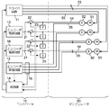
次に、本発明の好ましい実施の形態について図面を参照して説明する。図1は本発明の実施の一形態のロボットを示している。このロボットは、コントローラ10とマニピュレータ50とからなるものであり、マニピュレータ50は複数の軸を備えている。マニピュレータ50では、軸ごとに、モータ51とその軸のモータ51に機械的に接続するエンコーダ52とが設けられている。図示したものでは軸の数が4であるとしてモータ51とエンコーダ52との組が4組描かれているが、マニピュレータ50における軸の数は5以上であってもよい。
コントローラ10は、マニピュレータ50内の各軸のモータ51を駆動するドライバ回路11と、各軸のエンコーダ52に供給される電源電圧を生成するエンコーダ電源回路12と、各軸のエンコーダ52からモータ位置などを示す信号を受信するエンコーダ受信回路13と、マイクロプロセッサなどによって構成されてロボット全体の制御を行うために必要な演算などを実行する制御部14とを備えている。図では、説明のため、制御部14に関係する配線は破線で示されている。各軸のモータ51は、モータ51ごとに設けられているモータ配線53によってドライバ回路11に接続し、ドライバ回路11によって軸ごとに独立して駆動される。各軸のエンコーダ52に電源電圧を供給するために、少なくともマニピュレータ50内ではエンコーダ52ごとに個別電源配線54が設けられている。個別電源配線54は、コントローラ10内にも延びている。一方、エンコーダ電源回路12からは共通電源配線21を介して電源電圧が出力される。コントローラ10内において、共通電源配線21に対して軸ごとの個別電源配線54が軸ごとのスイッチ22を介して接続している。そしてコントローラ10には、個別電源配線54ごとに、その対応する個別電源配線54に接続して電圧を検出する電圧検出回路23が設けられている。個別電源配線54において電圧検出回路23が設けられる位置は、スイッチ22に近接しているがスイッチ22よりもエンコーダ52側となっている。したがって個別電源配線54は、一端がエンコーダ52に接続するとともに、他端側にスイッチ22及び電圧検出回路23が設けられていることになる。このロボットでは、各軸のエンコーダ52に対する電源電圧は、エンコーダ52に共通に設けられている共通電源配線21から、エンコーダ52ごとに設けられているスイッチ22及び個別電源配線54を介して供給されることになる。スイッチ22は、エンコーダ電源回路12に対する接続及び切放しをエンコーダ52ごとに実現する。
各軸のエンコーダ52からの信号は、エンコーダ52ごとに設けられた信号配線55を介してエンコーダ受信回路13に入力する。コントローラ10には、各信号配線55における信号電圧などを検出することにより信号配線55の断線を検出する断線検出回路15も設けられている。制御部14は、例えば外部から入力する位置指令と各エンコーダ52から入力する位置データとに基づいて、マニピュレータ50の位置が位置指令によって指定された位置となるようにドライバ回路11を介して各軸のモータ51を駆動する制御を実行するが、さらに、各スイッチ22のオン(導通)/オフ(遮断)やエンコーダ電源回路12を制御し、断線検出回路15からの入力や各電圧検出回路23での検出値に基づいて障害の発生の有無や障害箇所の特定を行う。制御部14からの制御を可能とするために、スイッチ22は、例えば、メカニカルリレーや半導体スイッチによって構成される。
本実施形態のロボットは、例えば、液晶表示パネルの製造に用いるガラス基板など搬送するためのロボットであり、大型のマニピュレータ50を備えるとともに、マニピュレータ50の移動距離も長いものである。そのため、マニピュレータ50内におけるモータ配線53、個別電源配線54及び信号配線55の長さも例えば数十mにも及ぶ。マニピュレータ50が動作して移動することによって、モータ配線53、個別電源配線54及び信号配線55もマニピュレータ50とともに移動し、その結果、曲げられたりねじられたりしてすなわち変形して種々のストレスを受けることになる。このようなストレスは配線における地絡や短絡、断線の原因ともなり得るものである。
従来のロボットでは、図2に示すように、エンコーダ電源回路12からの共通電源配線21がコントローラ10からマニピュレータ50まで延びるとともに、共通電源配線21の末端に対して各エンコーダ52からの個別電源配線54が直接接続していた。その結果、いずれかの軸の個別電源配線54において地絡などの障害が発生すると、エンコーダ電源回路12の出力が過電流によって遮断するか出力電圧が低下し、すべてのエンコーダ52に対する電源供給が停止する。電源電圧における異常を検出する機能を各エンコーダ52が備えている場合であっても、エンコーダ52からの信号によっては、どのエンコーダ52に接続する個別電源配線54において障害が発生したかを特定することができない。障害箇所の特定のためには、マニピュレータ50内の個別電源配線54の全てを目視によって点検せざるを得なくなる。液晶表示パネル用のガラス基板を搬送するロボットの場合、マニピュレータ50が大型化するとともに、マニピュレータ50自体がクリーンルームや減圧環境下に配置されるので、マニピュレータ50内の個別電源配線54の全てを点検してロボットを障害から復旧させることに多大な時間を要する。
これに対し図1に示した本実施形態のロボットでは、それぞれのエンコーダ52に接続する個別電源配線54において、エンコーダ電源回路12に接続する共通電源配線21に接続する位置からわずかにエンコーダ52よりの位置にスイッチ22を設けている。このスイッチ22は、個別電源配線54ごとすなわちエンコーダ52ごとに制御部14によって個別にオン/オフ制御することが可能である。そこでコントローラ10の電源が投入された直後などの時点において、エンコーダ52ごとのスイッチ22を個別にオンとし次いでオフとすることを各エンコーダ52に対して順番に実行する。このとき、オンとされたスイッチ22に対応するエンコーダ52からの信号をエンコーダ受信回路13において正しく受信することができれば、そのエンコーダ52に対応する個別電源配線54及び信号配線55はいずれも正常である、と判断することができる。これに対し、オンとされたスイッチ22に対応するエンコーダ52からの信号を正しくは受信できない場合には、そのエンコーダ52に対応する個別電源配線54及び信号配線55の少なくとも一方に地絡などの障害があると判定することができる。このとき、対応する個別電源配線54に接続されている電圧検出回路23において正しく電源電圧が検出できていれば、対応するエンコーダ52からの信号配線55に障害が生じたと判断することができる。反対に、1つのスイッチ22だけがオンとされ、かつそのスイッチに隣接して設けられている電圧検出回路23において電源電圧を検出できなければ、そのスイッチ22に接続する個別電源配線54における地絡または短絡が発生したと判断することができる。
本実施形態では、制御部14が1つずつスイッチ22を順番にオンとすることによって、どのエンコーダ52に接続する配線に障害が発生しているか、その障害が発生している配線が個別電源配線54か信号配線55であるかを容易に特定できるようになり、配線を目視等によって点検しなければならないとしても点検箇所を限定することができて、障害箇所の特定や障害からの復旧に要する時間を大幅に短縮することが可能になる。
本実施形態において電圧検出回路23は、入力電圧が正常であるかそうでないかを判別するだけの電圧コンパレータ回路から構成されていてもよい。しかしながら電圧検出回路23は、良否を示す二値信号を出力するものであるよりも、測定された電圧を電圧値として出力するものであることが好ましい。ここでいう電圧値は、アナログ値であってもよいし、アナログ/デジタル(A/D)変換機能などによって多値データとして表されたデジタル値であってもよい。電圧検出回路23がアナログ値または多値データである電圧値を検出する回路であり、エンコーダ52にもその供給される電源電圧を検出する回路が設けられているとすれば、電圧検出回路23で検出された電圧値とエンコーダ52において検出された電圧値とから、個別電源配線54における電圧降下量を求めることができる。大型のマニピュレータ50であれば個別電源配線54も長く、個別電源配線54によって供給される電源電圧での電圧降下を無視することはできない。エンコーダ52における消費電流は既知であって大きくは変動はしないから、個別電源配線54での電圧降下量とエンコーダ52の消費電流とから個別電源配線54の配線インピーダンスを算出することが可能となり、保守や設計マージンの確認が容易に行るようになる。電圧降下量や配線インピーダンスの変化を追跡することによって、配線における異常の発生や異常前の兆候の発見を容易に行えるようになる。エンコーダ52で実際に測定された電源電圧を制御部14にフィードバックし、制御部14がエンコーダ電源回路12を制御することによって、個別電源配線54での電圧降下量によらずにエンコーダ52に実際に供給される電源電圧値を適正値とすることができる。例えば制御部14は、電圧検出回路23で検出された電圧値とエンコーダ52において検出された電圧値との差を求め、この差に応じた電圧制御信号をエンコーダ電源回路12に出力する。
大型のマニピュレータ50の場合、モータ51やエンコーダ52がマニピュレータ50のどの軸のものであるかによって、モータ配線53、個別電源配線54及び信号配線55の長さが大きく異なることがある。個別電源配線54の長さが異なれば個別電源配線54における電圧降下量も異なることとなり、エンコーダ52に実際に供給される電源電圧も異なることとなる。個別電源配線54での電圧降下量が異なる場合、同一のエンコーダ電源回路12から複数のエンコーダ52に対して電源電圧を供給した場合にエンコーダ52ごとに実際に供給される電源電圧が異なり、上述したように電源電圧の測定値をフィードバックしてエンコーダ電源回路12を制御したとしても、すべてのエンコーダ52において実際の電源電圧を適正値にするような制御を行うことは難しい。その一方でエンコーダ52の数だけエンコーダ電源回路12を用意し、エンコーダ52に対してエンコーダ電源回路12から1対1で電源電圧を供給することは、コントローラ10を必要以上に大規模なものとする。
図3に示す本発明の別の実施形態のロボットは、図1に示すロボットと同様のものであるが、個別電源配線54の長さによってエンコーダ52に実際に供給される電源電圧がばらつくことを軽減するために、個別電源配線54の長さに応じて複数のエンコーダ52をいくつかの系統に分類し、系統ごとにエンコーダ電源回路12,16を設けるようにしたものである。図示したものでは2つのエンコーダ電源回路12,16が設けられおり、4個のエンコーダ52のうち、個別電源配線54の長さが相対的に短い2つのエンコーダ52に対してはエンコーダ電源回路12から電源電圧を供給し、個別電源配線54の長さが相対的に長い2つのエンコーダ52にはエンコーダ電源回路16から電源電圧を供給している。エンコーダ電源回路12,16は、それぞれ、制御部14からの制御によって出力電圧を調整できるものであるが、基本的にはこれらの出力電圧は、個別電源配線54における電圧降下量を加味したものとなっている。これにより、個別電源配線54の長さの違いによらずに各エンコーダ52をより適正値に近い電源電圧で駆動することが可能になる。エンコーダ電源回路12,16ごとに共通電源配線21が設けられること、各共通電源配線21から複数の個別電源配線54が分岐すること、個別電源配線54ごとにスイッチ22と電圧検出回路23が設けられることは、図1に示したものと同様である。
図3に示すロボットでは、それぞれのエンコーダ52に実際に供給された電源電圧に基づいてエンコーダ電源回路12,16の出力電圧のフィードバック制御を独立して行うことができる。電圧降下量の違いにもかかわらず、4個のエンコーダ52においてそれぞれのエンコーダ52に実際に供給される電圧のばらつきは小さくなり、これらのエンコーダ52に実際に供給される電源電圧を適正値により近づけることが可能になる。
図1に示したロボットではスイッチ22及び電圧検出回路23をコントローラ10内に設けているが、スイッチ22及び電圧検出回路23をマニピュレータ50内に設けることも可能である。図4に示すさらに別の実施形態のロボットは、図1に示すロボットにおいて、共通電源配線21をマニピュレータ50まで引き延ばすとともに、共通電源配線21からの個別電源配線54への分岐点とスイッチ22及び電圧検出回路23とをマニピュレータ50内に設け、さらに、スイッチ22を制御し電圧検出回路23から検出結果を受け取る制御部60を設けたものである。制御部60は、コントローラ10内に設けられている制御部14と協働してロボットの制御を行う。配線における障害は、その配線が変形する箇所において特に発生しやすいと考えられるから、障害をより確実に検出できるようにするために、スイッチ22及び電圧検出回路23は、個別電源配線54においてマニピュレータ50の移動に伴って移動する部分よりもコントローラ10の近い側に設けることが好ましい。具体的には、マニピュレータ50内においてコントローラ10と接続が行われる箇所の近傍において、共通電源配線21から個別電源配線54を分岐させるとともにスイッチ22及び電圧検出回路23を設けることが好ましい。
以上、本発明に基づくロボットを説明したが、本発明が適用されるものはロボットに限定されるものではない。本発明は、複数のエンコーダを有するエンコーダシステムであればどのようなものにも適用することができる。また、複数のモータを有するモータシステムであってモータごとにエンコーダが設けられるモータシステムに対しても本発明を適用することができる。
10 コントローラ
11 ドライバ回路
12,16 エンコーダ電源回路
13 エンコーダ受信回路
14,60 制御部
15 断線検出回路
21 共通電源配線
22 スイッチ
23 電圧検出回路
50 マニピュレータ
51 モータ
52 エンコーダ
53 モータ配線
54 個別電源配線
55 信号配線
11 ドライバ回路
12,16 エンコーダ電源回路
13 エンコーダ受信回路
14,60 制御部
15 断線検出回路
21 共通電源配線
22 スイッチ
23 電圧検出回路
50 マニピュレータ
51 モータ
52 エンコーダ
53 モータ配線
54 個別電源配線
55 信号配線
Claims (10)
- 複数のエンコーダと、
電源電圧を発生するエンコーダ電源回路と、
前記電源電圧を供給するために前記エンコーダごとに設けられて一端が当該エンコーダに接続する個別電源配線と、
前記個別電源配線ごとに当該個別電源配線の他端側に設けられて前記エンコーダ電源回路への接続と切放しとを切り替えるスイッチと、
前記個別電源配線ごとに当該個別電源配線の前記他端側において前記スイッチよりもエンコーダ側に設けられた第1の電圧検出回路と、
を有する、エンコーダシステム。 - 前記第1の電圧検出回路は電圧値を出力し、
前記エンコーダは、供給された電源電圧を検出して電圧値として出力する第2の電圧検出回路を備える、請求項1に記載のエンコーダシステム。 - 前記第1の電圧検出回路で検出した電圧値と前記第2の電圧検出回路で検出した電圧値との差を演算する演算手段を有する、請求項2に記載のエンコーダシステム。
- 前記演算手段は、前記差に応じた電源制御信号を前記エンコーダ電源回路に出力する、請求項3に記載のエンコーダシステム。
- 前記個別電源配線の長さに応じて前記複数のエンコーダが複数の系統に分類され、系統ごとに前記エンコーダ電源回路が設けられている、請求項1乃至4のいずれか1項に記載のエンコーダシステム。
- 複数のモータを備えるモータシステムであって、
請求項1乃至5のいずれか1項に記載のエンコーダシステムを備え、前記モータごとに前記エンコーダシステムの前記エンコーダが設けられている、モータシステム。 - 複数のモータを備えるマニピュレータと前記マニピュレータを制御するコントローラとを有するロボットであって、
請求項1乃至5のいずれか1項に記載のエンコーダシステムを備え、前記モータごとに前記エンコーダシステムの前記エンコーダが設けられているロボット。 - 前記個別電源配線ごとの前記第1の電圧検出回路と前記エンコーダとの間の区間に、前記マニピュレータの移動に伴って当該個別電源配線が変形する区間が含まれる、請求項7に記載のロボット。
- 前記スイッチ及び前記第1の電圧検出回路が前記コントローラに配置される、請求項7または8に記載のロボット。
- 前記スイッチ及び前記第1の電圧検出回路が前記マニピュレータに配置される、請求項7または8に記載のロボット。
Priority Applications (2)
| Application Number | Priority Date | Filing Date | Title |
|---|---|---|---|
| KR1020227003465A KR102903766B1 (ko) | 2019-08-06 | 2020-07-13 | 인코더 시스템, 모터 시스템 및 로봇 |
| CN202080053666.7A CN114206564B (zh) | 2019-08-06 | 2020-07-13 | 编码器系统、马达系统以及机器人 |
Applications Claiming Priority (2)
| Application Number | Priority Date | Filing Date | Title |
|---|---|---|---|
| JP2019-144423 | 2019-08-06 | ||
| JP2019144423A JP7565152B2 (ja) | 2019-08-06 | 2019-08-06 | エンコーダシステム、モータシステム及びロボット |
Publications (1)
| Publication Number | Publication Date |
|---|---|
| WO2021024706A1 true WO2021024706A1 (ja) | 2021-02-11 |
Family
ID=74504009
Family Applications (1)
| Application Number | Title | Priority Date | Filing Date |
|---|---|---|---|
| PCT/JP2020/027243 Ceased WO2021024706A1 (ja) | 2019-08-06 | 2020-07-13 | エンコーダシステム、モータシステム及びロボット |
Country Status (5)
| Country | Link |
|---|---|
| JP (1) | JP7565152B2 (ja) |
| KR (1) | KR102903766B1 (ja) |
| CN (1) | CN114206564B (ja) |
| TW (1) | TWI728874B (ja) |
| WO (1) | WO2021024706A1 (ja) |
Cited By (1)
| Publication number | Priority date | Publication date | Assignee | Title |
|---|---|---|---|---|
| CN115514084A (zh) * | 2022-11-03 | 2022-12-23 | 广东隆崎机器人有限公司 | 一种六轴机器人的多电源安全模块及其控制方法 |
Families Citing this family (2)
| Publication number | Priority date | Publication date | Assignee | Title |
|---|---|---|---|---|
| JP2022127744A (ja) * | 2021-02-22 | 2022-09-01 | 株式会社三共 | 遊技機 |
| CN119773174A (zh) * | 2025-01-06 | 2025-04-08 | 克劳斯玛菲机械(中国)有限公司 | 单驱动控制的多轴驱动设备及其控制方法 |
Citations (4)
| Publication number | Priority date | Publication date | Assignee | Title |
|---|---|---|---|---|
| JP3022656U (ja) * | 1995-09-13 | 1996-03-26 | 廣 小林 | 製本機械における位置決めモータ制御装置 |
| JPH10203740A (ja) * | 1997-01-27 | 1998-08-04 | Mitsubishi Electric Corp | エレベーターの異常時制御装置 |
| WO2016174755A1 (ja) * | 2015-04-29 | 2016-11-03 | 富士機械製造株式会社 | モータ駆動装置 |
| WO2019116551A1 (ja) * | 2017-12-15 | 2019-06-20 | 三菱電機株式会社 | モータ駆動システム及びインバータ装置 |
Family Cites Families (22)
| Publication number | Priority date | Publication date | Assignee | Title |
|---|---|---|---|---|
| JPS618302U (ja) * | 1984-06-20 | 1986-01-18 | トキコ株式会社 | 工業用ロボツト |
| JPH0647239B2 (ja) * | 1985-09-11 | 1994-06-22 | フアナツク株式会社 | ロボツト用エンコ−ダの電源装置 |
| JPH02269429A (ja) * | 1989-04-11 | 1990-11-02 | Hitachi Ltd | バツクアップ電源異常監視装置 |
| JPH02292197A (ja) * | 1989-04-28 | 1990-12-03 | Mitsubishi Electric Corp | 産業用ロボット |
| JPH08251817A (ja) | 1995-03-13 | 1996-09-27 | Yaskawa Electric Corp | エンコーダ用補助電源システム |
| JP4175377B2 (ja) | 1997-10-08 | 2008-11-05 | 株式会社デンソーウェーブ | ロボット制御装置 |
| JP2000210891A (ja) | 1999-01-19 | 2000-08-02 | Yaskawa Electric Corp | ロボット駆動装置の安全保護装置 |
| JP2001150374A (ja) | 1999-11-25 | 2001-06-05 | Sony Corp | ロボットの故障診断システム |
| JP4898847B2 (ja) * | 2007-02-14 | 2012-03-21 | 株式会社五合 | 移動操作装置及び三次元移動装置 |
| JP2010206951A (ja) * | 2009-03-04 | 2010-09-16 | Yaskawa Electric Corp | モータ制御装置 |
| JP2010284746A (ja) | 2009-06-11 | 2010-12-24 | Nitta Ind Corp | 継手及び自動工具交換装置 |
| WO2011126574A1 (en) * | 2010-04-09 | 2011-10-13 | William Howard Speegle | Methods and systems for controlling devices via power lines |
| JP5601105B2 (ja) * | 2010-09-10 | 2014-10-08 | 株式会社デンソーウェーブ | ロボットシステム |
| JP3164700U (ja) | 2010-09-30 | 2010-12-09 | 株式会社石川鉄工所 | 管路検査装置 |
| JP2013052475A (ja) * | 2011-09-05 | 2013-03-21 | Denso Wave Inc | ロボットシステム |
| US8736684B1 (en) * | 2013-02-08 | 2014-05-27 | Omnivision Technologies, Inc. | System and method for sensor failure detection |
| JP5549775B2 (ja) * | 2013-10-24 | 2014-07-16 | ダイキン工業株式会社 | 空気調和機 |
| JP5945973B2 (ja) | 2013-11-05 | 2016-07-05 | 株式会社安川電機 | エンコーダ、エンコーダ付きモータ、サーボシステム、エンコーダの信号処理方法 |
| JP6367546B2 (ja) | 2013-12-17 | 2018-08-01 | Dxアンテナ株式会社 | 電力供給装置 |
| JP2016052223A (ja) * | 2014-09-02 | 2016-04-11 | ソムフィ株式会社 | モータ駆動装置 |
| JP6525637B2 (ja) | 2015-02-26 | 2019-06-05 | キヤノン株式会社 | ロボット装置及びロボット装置の制御方法 |
| JP2017196700A (ja) | 2016-04-27 | 2017-11-02 | ライフロボティクス株式会社 | ロボット装置及び電子機器 |
-
2019
- 2019-08-06 JP JP2019144423A patent/JP7565152B2/ja active Active
-
2020
- 2020-07-13 WO PCT/JP2020/027243 patent/WO2021024706A1/ja not_active Ceased
- 2020-07-13 CN CN202080053666.7A patent/CN114206564B/zh active Active
- 2020-07-13 KR KR1020227003465A patent/KR102903766B1/ko active Active
- 2020-07-22 TW TW109124654A patent/TWI728874B/zh active
Patent Citations (4)
| Publication number | Priority date | Publication date | Assignee | Title |
|---|---|---|---|---|
| JP3022656U (ja) * | 1995-09-13 | 1996-03-26 | 廣 小林 | 製本機械における位置決めモータ制御装置 |
| JPH10203740A (ja) * | 1997-01-27 | 1998-08-04 | Mitsubishi Electric Corp | エレベーターの異常時制御装置 |
| WO2016174755A1 (ja) * | 2015-04-29 | 2016-11-03 | 富士機械製造株式会社 | モータ駆動装置 |
| WO2019116551A1 (ja) * | 2017-12-15 | 2019-06-20 | 三菱電機株式会社 | モータ駆動システム及びインバータ装置 |
Cited By (2)
| Publication number | Priority date | Publication date | Assignee | Title |
|---|---|---|---|---|
| CN115514084A (zh) * | 2022-11-03 | 2022-12-23 | 广东隆崎机器人有限公司 | 一种六轴机器人的多电源安全模块及其控制方法 |
| CN115514084B (zh) * | 2022-11-03 | 2023-03-21 | 广东隆崎机器人有限公司 | 一种六轴机器人的多电源安全模块及其控制方法 |
Also Published As
| Publication number | Publication date |
|---|---|
| JP2021025896A (ja) | 2021-02-22 |
| TW202107858A (zh) | 2021-02-16 |
| KR20220027221A (ko) | 2022-03-07 |
| TWI728874B (zh) | 2021-05-21 |
| KR102903766B1 (ko) | 2025-12-24 |
| CN114206564B (zh) | 2024-02-02 |
| CN114206564A (zh) | 2022-03-18 |
| JP7565152B2 (ja) | 2024-10-10 |
Similar Documents
| Publication | Publication Date | Title |
|---|---|---|
| KR102903766B1 (ko) | 인코더 시스템, 모터 시스템 및 로봇 | |
| JP4835842B2 (ja) | ビルディングブロック型のセーフティ・コントローラにおけるioユニット | |
| EP1705539B1 (en) | Emergency-stop device | |
| JP3896237B2 (ja) | 制御システム | |
| US10579558B1 (en) | Flexible redundant input/output (I/O) schemes for I/O channels | |
| US11396954B2 (en) | Electromagnetic valve system | |
| EP3572194B1 (en) | Robot system and robot controller | |
| US7555680B2 (en) | Distributed control apparatus | |
| CN107155370A (zh) | 搬送装置的控制装置 | |
| US20240160589A1 (en) | I/o unit | |
| CN113900397A (zh) | 一种实现rs-485信号线反接自适应切换的装置 | |
| JP7684108B2 (ja) | ロボットシステム及びその誤配線検出方法 | |
| KR101231165B1 (ko) | 점검기능을 구비한 무대장치 제어시스템 | |
| US7709978B2 (en) | System interface and installation with the system interface | |
| US20200249655A1 (en) | System | |
| GB2474869A (en) | Robot control cable bypass apparatus | |
| WO2020149153A1 (ja) | 環境制御システム、空気調和機または空気調和システム | |
| US7099730B2 (en) | Terminal table unit | |
| JP5333838B2 (ja) | Fa機器 | |
| CN120089108B (zh) | 栅极走线修复电路及其方法以及显示面板 | |
| ITMI20071007A1 (it) | Dispositivo e procedimento per evitare collisioni assiali | |
| CN117250559A (zh) | 编码器配线的故障检测装置 | |
| JP2008030164A (ja) | ロボット制御装置 | |
| JPS6388607A (ja) | シ−ケンスコントロ−ラ用の出力ユニツト | |
| JP2016206928A (ja) | プラントの臨時監視システム |
Legal Events
| Date | Code | Title | Description |
|---|---|---|---|
| 121 | Ep: the epo has been informed by wipo that ep was designated in this application |
Ref document number: 20849255 Country of ref document: EP Kind code of ref document: A1 |
|
| ENP | Entry into the national phase |
Ref document number: 20227003465 Country of ref document: KR Kind code of ref document: A |
|
| NENP | Non-entry into the national phase |
Ref country code: DE |
|
| 122 | Ep: pct application non-entry in european phase |
Ref document number: 20849255 Country of ref document: EP Kind code of ref document: A1 |