WO2021024692A1 - Dispositif de commande audio, système audio, programme, et procédé de commande audio - Google Patents
Dispositif de commande audio, système audio, programme, et procédé de commande audio Download PDFInfo
- Publication number
- WO2021024692A1 WO2021024692A1 PCT/JP2020/026939 JP2020026939W WO2021024692A1 WO 2021024692 A1 WO2021024692 A1 WO 2021024692A1 JP 2020026939 W JP2020026939 W JP 2020026939W WO 2021024692 A1 WO2021024692 A1 WO 2021024692A1
- Authority
- WO
- WIPO (PCT)
- Prior art keywords
- speaker
- directional
- directional speaker
- audio
- frequency characteristic
- Prior art date
Links
Images


Classifications
-
- H—ELECTRICITY
- H04—ELECTRIC COMMUNICATION TECHNIQUE
- H04R—LOUDSPEAKERS, MICROPHONES, GRAMOPHONE PICK-UPS OR LIKE ACOUSTIC ELECTROMECHANICAL TRANSDUCERS; DEAF-AID SETS; PUBLIC ADDRESS SYSTEMS
- H04R3/00—Circuits for transducers, loudspeakers or microphones
- H04R3/04—Circuits for transducers, loudspeakers or microphones for correcting frequency response
-
- H—ELECTRICITY
- H04—ELECTRIC COMMUNICATION TECHNIQUE
- H04R—LOUDSPEAKERS, MICROPHONES, GRAMOPHONE PICK-UPS OR LIKE ACOUSTIC ELECTROMECHANICAL TRANSDUCERS; DEAF-AID SETS; PUBLIC ADDRESS SYSTEMS
- H04R3/00—Circuits for transducers, loudspeakers or microphones
- H04R3/12—Circuits for transducers, loudspeakers or microphones for distributing signals to two or more loudspeakers
-
- H—ELECTRICITY
- H04—ELECTRIC COMMUNICATION TECHNIQUE
- H04R—LOUDSPEAKERS, MICROPHONES, GRAMOPHONE PICK-UPS OR LIKE ACOUSTIC ELECTROMECHANICAL TRANSDUCERS; DEAF-AID SETS; PUBLIC ADDRESS SYSTEMS
- H04R5/00—Stereophonic arrangements
- H04R5/02—Spatial or constructional arrangements of loudspeakers
-
- H—ELECTRICITY
- H04—ELECTRIC COMMUNICATION TECHNIQUE
- H04S—STEREOPHONIC SYSTEMS
- H04S7/00—Indicating arrangements; Control arrangements, e.g. balance control
Definitions
- the present invention relates to an audio controller, an audio system, a program, and an audio control method.
- Japanese Patent Application Laid-Open No. 2017-163432 discloses that a surround system is constructed by using a reflective ultrasonic speaker.
- the volume of the output sound at which the volume of the reflected sound from the virtual sound source becomes a predetermined level is adjusted.
- the combination of audible sound output from the directional speaker and audible sound output from the omnidirectional speaker is listening. It will be an experience. In general, the higher the frequency band, the higher the directivity. Therefore, trying to output low-band audible sound to a directional speaker tends to reduce the quality of the listening experience. Especially in the case of ultrasound, the demodulation rate in the low frequency band is low, so the quality of the listening experience in the low frequency band is low.
- JP-A-2017-163432 does not improve the quality of the listening experience because each of the reflective ultrasonic speaker and the omnidirectional speaker is controlled individually.
- An object of the present invention is to improve the quality of listening experience in an audio system using directional speakers and omnidirectional speakers.
- the present invention An audio controller that controls directional speakers and omnidirectional speakers. Equipped with a means to acquire a multi-channel audio input signal A means for controlling the directional speaker so as to output an audible sound corresponding to the first portion of the directional speaker channel audio input signal among the multi-channel audio input signals is provided. A means for controlling the omnidirectional speaker is provided so as to output an audible sound corresponding to the second portion of the audio input signal of the directional speaker channel. It is an audio controller.
- FIG. 1 It is a block diagram which shows the structure of the audio system of this embodiment. It is a functional block diagram of the audio system of FIG. It is the schematic which shows the layout of the audio system of FIG. It is the schematic of the surround environment realized by the audio system of FIG. It is explanatory drawing of the outline of this embodiment. It is a sequence diagram of the setup process of this embodiment. It is a figure which shows the example of the screen displayed by the process of FIG. It is a sequence diagram of the audio reproduction processing of this embodiment. It is a detailed flowchart of the audio signal processing of FIG. It is the schematic of the frequency characteristic signal concerning the audio signal processing of FIG. It is a functional block diagram of the audio system of the modification 1. It is explanatory drawing of the outline of the direction change mechanism of FIG.
- directionality means a property of traveling in a specific direction (for example, going straight).
- omnidirectional means a property of propagating (eg, diffusing) radially from an output source as compared to directional.
- the "directional speaker channel” means a channel of an audio input signal including high-band sound suitable for the output characteristics of the directional speaker.
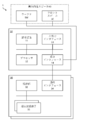
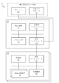
- FIG. 1 is a block diagram showing a configuration of an audio system of the present embodiment.
- FIG. 2 is a functional block diagram of the audio system of FIG.
- the audio system 1 includes a sound source device SS, a monitor MT, an omnidirectional speaker 40 (for example, a front speaker LC and a woofer SW), an audio controller 10, and a directional speaker 30. Be prepared.
- the omnidirectional speaker 40 and the directional speaker 30 form a surround system. This surround system is arranged in the use space SP (for example, indoors). The surround system provides the listener TL with a video and audio user experience.
- the sound source device SS is configured to output an audio input signal of audio content provided via a storage medium or communication.
- the sound source device SS is, for example, an audio player.
- the sound source device SS includes, for example, at least one of the following.
- -A device that plays back a storage medium in which music data is stored for example, a CD (Compact Disc) player or a Blu-ray player).
- -Computer with music playback application installed for example, smartphone or portable music player
- the monitor MT is configured to output an image (still image or moving image).
- the omnidirectional speaker 40 is configured to present sound by outputting omnidirectional sound waves.
- the directional speaker 30 is configured to present sound by outputting directional sound waves (for example, ultrasonic waves modulated according to a predetermined modulation method).
- the modulation method is, for example, any of the following. ⁇ AM (Amplitude Modulation) modulation ⁇ FM (Frequency Modulation) modulation ⁇ PM (Phase Modulation) modulation
- the audio controller 10 is configured to control the monitor MT, the omnidirectional speaker 40, and the directional speaker 30.
- the audio controller 10 includes a storage device 11, a processor 12, an input / output interface 13, and a communication interface 14.
- the storage device 11 is configured to store programs and data.
- the storage device 11 is, for example, a combination of a ROM (Read Only Memory), a RAM (Random Access Memory), and a storage (for example, a flash memory or a hard disk).
- the program includes, for example, the following program.
- -OS Operating System
- Program-Application program that executes control processing of the omnidirectional speaker 40 and the directional speaker 30
- the data includes, for example, the following data.
- -Database referenced in information processing-Data obtained by executing information processing that is, the execution result of information processing
- the processor 12 is configured to realize the function of the audio controller 10 by activating the program stored in the storage device 11.
- the processor 12 is an example of a computer.
- the functions of the audio controller 10 include, for example, the following. -A function to generate a monitor control signal for controlling the monitor MT-A function to generate a speaker control signal for controlling the omnidirectional speaker 40 and the directional speaker 30-The omnidirectional speaker via the communication interface 14.
- the input / output interface 13 is configured to acquire a user's instruction from an input device connected to the audio controller 10 and output information to an output device connected to the audio controller 10.
- the input device is, for example, a keyboard, a pointing device, a touch panel, a microphone, or a combination thereof.
- the output device is, for example, a monitor MT.
- the communication interface 14 is configured to control communication between the audio controller 10, the monitor MT, the omnidirectional speaker 40, and the directional speaker 30.
- the directional speaker 30 includes a drive unit 32, a communication interface 34, and a plurality of ultrasonic vibrators 35.
- the drive unit 32 is configured to generate a drive signal (hereinafter referred to as "oscillator drive signal") for driving the ultrasonic oscillator 35 according to the speaker control signal output from the audio controller 10.
- oscillator drive signal a drive signal for driving the ultrasonic oscillator 35 according to the speaker control signal output from the audio controller 10.
- the communication interface 34 is configured to control communication between the directional speaker 30 and the audio controller 10.
- the plurality of ultrasonic vibrators 35 are configured to radiate ultrasonic waves by vibrating based on the vibrator drive signal generated by the drive unit 32.
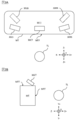
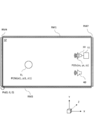
- FIG. 3 is a schematic diagram showing the layout of the audio system of FIG.
- FIG. 4 is a schematic diagram of the surround environment realized by the audio system of FIG.
- the listener TL exists at a position (hereinafter referred to as "reference listener position") in the direction (Z direction) facing the display surface MTF of the monitor MT.
- the directional speaker 30 includes a plurality of (for example, 6) directional speaker components (up-firing directional speaker 30CT, side firing directional speaker 30LS and 30RS, and back-firing directional speaker 30LB and 30RB). Consists of. Each directional speaker component is arranged, for example, in the horizontal plane of the top plate MTT of the monitor MT.
- the up-firing directional speaker 30CT is arranged so that the radial surface faces the upper side (Y + direction) of the listener TL (FIG. 3B).
- the side firing directional speaker 30LS is arranged so that the radial surface faces the left side (X ⁇ side) of the listener TL (FIG. 3A).
- the side firing directional speaker 30RS is arranged so that the radial surface faces the wall on the right side (X + side) of the listener TL (FIG. 3A).
- the backfire ring directional speaker 30LB is arranged so that the radiation surface faces the wall on the left side (X ⁇ side) of the listener TL and is non-parallel to the radiation surface of the backfire ring directional speaker 30RB (FIG. 3A). ..
- the backfire ring directional speaker 30RB has a radiation surface facing the wall on the right side (X + side) of the listener TL, and is arranged non-parallel to the radiation surface of the back fire ring directional speaker 30LB (FIG. 3A).
- the audio SBC output from the front speaker LC travels in the direction toward the listener TL (Z + direction).
- the audio SBW output from the woofer SW proceeds in the direction toward the listener TL (Z + direction).
- the ultrasonic UBT radiated from the up-firing directional speaker 30CT is reflected by the ceiling of the used space SP and travels in the direction (Y- direction) from the ceiling to the listener TL.
- the ultrasonic UBSL radiated from the side firing directional speaker 30LS is reflected by the wall located on the left side (Y ⁇ side) of the listener TL, and travels in the direction (X + direction) from the wall toward the listener TL.
- the ultrasonic UBSR emitted from the side firing directional speaker 30RS is reflected by the wall located on the right side (Y + side) of the listener TL, and travels in the direction (X- direction) from the wall toward the listener TL.
- the ultrasonic UBRL emitted from the back-firing directional speaker 30LB is reflected by the walls located on the left side (X- side) of the listener TL and behind the listener TL (Z + direction), and is reflected behind the listener TL (Z + direction). ) Toward the listener TL (Z- direction).
- the ultrasonic UBRR emitted from the back-firing directional speaker 30RB is reflected by the walls located on the right side (X + side) of the listener TL and behind the listener TL (Z + direction), and is reflected behind the listener TL (Z + direction). Proceed in the direction from the wall to the speaker TL (Z- direction).
- FIG. 5 is an explanatory diagram of an outline of the present embodiment.
- the audio controller 10 has the following functions.
- -A function to acquire a multi-channel audio input signal-Of the multi-channel audio input signals, the first part of the audio input signal of the channel to be output by the directional speaker 30 (hereinafter referred to as "directional speaker channel”) can be supported.
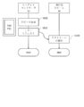
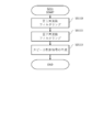
- FIG. 6 is a sequence diagram of the setup process of the present embodiment.
- FIG. 7 is a diagram showing an example of a screen displayed by the process of FIG.
- the audio controller 10 executes the speaker setting (S110). Specifically, the processor 12 displays the screen P10 (FIG. 7) on the display.
- the screen P10 includes operation objects B10a to B10b.
- the operation object B10a is an object that receives a user instruction for starting the setup.
- the operation object B10b is an object that receives a user instruction for starting the voice reproduction process.
- the processor 12 displays the screen P11 (FIG. 7) on the display.
- the screen P11 includes an operation object B11 and field objects F11a to F11c for each speaker position according to the number of channels of the surround system.
- the speaker positions include: ⁇ Center ⁇ Left side firing ⁇ Right side firing ⁇ Left back firing ⁇ Right back firing ⁇ Upfire ring ⁇ Subwoofer
- the field object F11a is an object that receives input of speaker identification information that identifies the speaker.
- the speaker identification information is acquired by the processor 12 from each speaker when each speaker and the audio controller 10 are connected.
- the field object F11b is an object that accepts the input of the value of the distance of each speaker (hereinafter referred to as “speaker distance”) based on the assumed position of the listener TL.
- the field object F11c is an object that receives the input of the volume of each speaker.
- the operation object B11 is an object that receives a user instruction of a test request (S111).
- the user inputs the speaker identification information of the processor to be assigned to each speaker arrangement in the field object F11a, inputs the speaker distance of each speaker in the field object F11b, inputs the volume of each speaker in the field object F11c, and operates the operation object B11.
- the processor 12 stores the setting information in the storage device 11.
- the setting information includes the information input to the field objects F11a to F11c.
- the audio controller 10 executes a test request (S111). Specifically, the processor 12 transmits a test request signal to the front speaker LC, the woofer SW, and the directional speaker 30.
- the directional speaker 30 executes the reproduction of the test tone (S130).
- the up-firing directional speaker 30CT, the side-firing directional speakers 30LS and 30RS, and the drive unit 32 of the back-firing directional speakers 30LB and 30RB are the test request signals transmitted from the audio controller 10.
- a drive signal for reproducing the test tone is generated according to the above.
- the ultrasonic oscillator 35 vibrates in response to a drive signal generated by the drive unit 32 to emit ultrasonic waves for outputting a test tone.
- the front speaker LC and the woofer SW output a test tone corresponding to the test request signal transmitted from the audio controller 10.
- the listener TL While listening to the test tone, the listener TL directs the radial surfaces of the up-firing directional speakers 30CT, the side-firing directional speakers 30LS and 30RS, and the back-firing directional speakers 30LB and 30RB, respectively (hereinafter, "radiation"). It can be determined whether the "direction") reproduces the desired listening environment.
- FIG. 8 is a sequence diagram of the audio reproduction processing of the present embodiment.
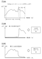
- FIG. 9 is a detailed flowchart of the audio signal processing of FIG.
- FIG. 10 is a schematic diagram of a frequency characteristic signal related to the audio signal processing of FIG.
- acquisition of the voice input signal (S210) is executed. Specifically, the processor 12 displays the screen P10 (FIG. 7) on the display. When the user operates the operation object B10b, the processor 12 acquires the multi-channel audio input signal of the audio content from the sound source device SS.
- the multi-channel audio input signal includes a channel audio input signal corresponding to each of a plurality of speakers constituting the surround system.
- step S210 the audio controller 10 executes audio signal processing (S211).
- the audio controller 10 executes equalizing (S2110) of the directional speaker.
- the storage device 11 stores an equalizing model according to the output frequency characteristic of the directional speaker 30.
- the equalizing model the volume and output frequency characteristics of the directional speaker 30 and the correlation of the equalizer coefficient are defined.
- the processor 12 refers to the equalizing model, and among the user instructions given to the field object F11c, the user instruction corresponding to the directional speaker 30 (that is, the volume of the directional speaker 30 specified by the user) and the directivity.
- the equalizer coefficient of the directional speaker 30 (hereinafter referred to as "first equalizer coefficient") is determined according to the combination of the output frequency characteristics of the speaker 30.
- the first equalizer coefficient is a coefficient that emphasizes, for example, a band (for example, a high frequency band) having a strong influence (that is, directivity) on the sense of localization or surround sound.
- the directional speaker channel corresponds to the following speaker positions. ⁇ Left side firing ⁇ Right side firing ⁇ Left back firing ⁇ Right back firing ⁇ Upfire ring
- the processor 12 applies the first equalizer coefficient to the audio input signal of the directional speaker channel to obtain the audio input signal of the directional speaker channel (FIG. 10A). It is converted into a first frequency characteristic signal (FIG. 10B).
- omnidirectional speaker equalization for the directional speaker channel is performed.
- the processor 12 identifies a speaker (for example, a front speaker LC) that is suitable for output in a band that is not suitable for output from the directional speaker 30 among the omnidirectional speakers 40.
- the processor 12 determines the equalizer coefficient (hereinafter referred to as “second equalizer coefficient”) of the omnidirectional speaker 40 with respect to the directional speaker channel with reference to the first equalizer coefficient obtained in step S2110.
- the second equalizer coefficient is different from the first equalizer coefficient.
- the second equalizer coefficient is, for example, a coefficient that emphasizes a band having a weak influence on the sense of localization (for example, a low frequency band) as compared with the first equalizer coefficient.
- the processor 12 converts the audio input signal of the directional speaker channel (FIG. 10A) into the second frequency characteristic signal (FIG. 10C) by applying the second equalizer coefficient to the audio input signal of the directional speaker channel.
- the audio controller 10 outputs the audible sound corresponding to the audio input signal of the directional speaker channel from the directional speaker 30 and the omnidirectional speaker 40.
- the audio controller 10 adjusts the ratio of the first frequency characteristic signal given to the directional speaker 30 and the second frequency characteristic signal given to the omnidirectional speaker 40. As a result, it is possible to improve the balance of the sound quality, localization, and surround sound of the audible sound corresponding to the audio input signal of the directional speaker channel.
- Step S2112 the audio controller 10 executes omnidirectional speaker equalization (S2112) with respect to the omnidirectional speaker channel.
- Step S2112 is equalization of the audio input signal of the channel to be output by the omnidirectional speaker 40 (hereinafter referred to as “omnidirectional speaker channel”) among the multi-channel audio input signals obtained in step S210.
- the processor 12 includes the user instruction corresponding to the front speaker LC (that is, the volume of the front speaker LC specified by the user) among the user instructions given to the field object F11c, and the output frequency of the front speaker LC.
- the equalizer coefficient of the front speaker LC (hereinafter referred to as "front speaker equalizer coefficient") with respect to the channel to be output by the front speaker LC (hereinafter referred to as "front speaker channel”) among the omnidirectional speaker channels decide.
- the processor 12 applies the audio input signal of the front speaker channel to the frequency characteristic signal according to the output frequency characteristic of the front speaker LC (hereinafter, “front speaker frequency characteristic”). Convert to "signal").
- the processor 12 refers to the combination of the user instruction corresponding to the woofer SW (that is, the volume of the woofer SW specified by the user) and the output frequency characteristic of the woofer SW among the user instructions given to the field object F11c.
- the equalizer coefficient hereinafter referred to as "woofa equalizer coefficient" of the woofer SW with respect to the channel to be output by the woofer SW (hereinafter referred to as "woofer channel”) is determined.
- the processor 12 applies the woofer colliser coefficient to the audio input signal of the woofer channel to convert the audio input signal of the woofer channel into a frequency characteristic signal (hereinafter referred to as "woofer frequency characteristic signal”) corresponding to the output frequency characteristic of the woofer SW. Convert.
- woofer frequency characteristic signal a frequency characteristic signal
- the audio controller 10 executes the generation of the speaker control signal (S2113).
- the processor 12 refers to the first frequency characteristic signal obtained in step S2110 to generate a speaker control signal (hereinafter referred to as “directional speaker control signal”) for controlling the directional speaker 30.
- directional speaker control signal is an example of the “first speaker control signal”.
- the processor 12 synthesizes the second frequency characteristic signal obtained in step S2111 and the front speaker frequency characteristic signal obtained in step S2112.
- the processor 12 refers to the combined signal to generate a speaker control signal (hereinafter referred to as “front speaker control signal”) for controlling the front speaker LC.
- the front speaker control signal is an example of the “second speaker control signal”.
- the processor 12 refers to the woofer speaker characteristic signal obtained in step S2112 to generate a speaker control signal (hereinafter referred to as “woofer control signal”) for controlling the woofer SW.
- the woofer control signal is an example of a "second speaker control signal”.
- the audio controller 10 executes speaker control (S212). Specifically, the processor 12 identifies the speaker control signals (directional speaker control signal, front speaker control signal, and woofer control signal) obtained in step S211 by the speaker identification information corresponding to each channel signal. It is transmitted to the speakers (front speaker LC, woofer SW, up-firing directional speaker 30CT, side firing directional speakers 30LS and 30RS, and back-firing directional speakers 30LB and 30RB).
- the speakers front speaker LC, woofer SW, up-firing directional speaker 30CT, side firing directional speakers 30LS and 30RS, and back-firing directional speakers 30LB and 30RB.
- the directional speaker 30 executes radiation of directional sound waves (S230).
- the drive unit 32 generates an oscillator drive signal for radiating ultrasonic waves corresponding to the directional speaker control signal transmitted from the audio controller 10.
- a voltage is applied to each ultrasonic oscillator 35 according to the oscillator drive signal generated by the drive unit 32.
- Each ultrasonic oscillator 35 vibrates according to the applied voltage. As a result, ultrasonic waves with radiated sound pressure corresponding to the volume included in the setting information are emitted.
- the front speaker LC and the woofer SW output audible sounds corresponding to the speaker control signals (front speaker control signal and woofer control signal) transmitted from the audio controller 10, respectively.
- the listener TL perceives the audible sounds output from the front speakers LC and the woofer SW as sounds arriving from the positions of the respective speakers.
- the ultrasonic waves radiated from the up-firing directional speaker 30CT are reflected by the ceiling of the space SP used, and then travel from above the listener TL (Y + direction) toward the listener TL.
- the listener TL perceives the audible sound output from the up-firing directional speaker 30CT as the sound coming from the ceiling.
- the ultrasonic waves radiated from the side firing directional speakers 30LS and 30RS are reflected by the wall of the used space SP and then travel from the left and right sides of the listener TL toward the listener TL.
- the listener TL perceives the audible sound output from the side firing directional speakers 30LS and 30RS as the sound coming from the left and right walls of the listener TL.
- the ultrasonic waves radiated from the back-firing directional speakers 30LB and 30RB are reflected by the wall of the used space SP, and then travel from behind the listener TL (Z + direction) toward the listener TL.
- the listener TL perceives the audible sound output from the back firing directional speakers 30LB and 30RB as the sound coming from the wall behind the listener TL.
- the audio controller 10 outputs the first audible sound corresponding to the first portion (for example, the first frequency characteristic signal) of the audio input signals of the directional speaker channel from the directional speaker 30.
- the omnidirectional speaker 40 outputs a second audible sound corresponding to a second portion (for example, a second frequency characteristic signal) different from the first portion among the audio input signals of the directional speaker channel.
- the listening experience includes, for example, at least one of the following: ⁇ Volume ⁇ Sound spread (that is, surround sound) ⁇ A sense of localization
- the audio controller 10 converts the audio input signal of the directional speaker channel into the first frequency characteristic signal by using the first equalizer coefficient corresponding to the output frequency characteristic of the directional speaker 30.
- the audio input signal of the directional speaker channel is converted into the second frequency characteristic signal by using the second equalizer coefficient different from the first equalizer coefficient. This can further improve the quality of the listening experience.
- the audio controller 10 determines the first equalizer coefficient according to the combination of the output frequency characteristic of the directional speaker 30 and the volume output from the directional speaker 30. As a result, the user's desired surround environment can be constructed.
- Modification 1 is an example of a directional speaker 30 capable of changing the radiation direction of directional sound waves.
- FIG. 11 is a functional block diagram of the audio system of the first modification.
- the directional speaker 30 has the same configuration as that of the present embodiment (FIG. 2) (drive unit 32, communication interface 34, and a plurality of ultrasonic vibrators 35), and also has a direction changing mechanism. 36 is provided.
- the drive unit 32 is configured to generate a drive signal (hereinafter referred to as “mechanism drive signal”) for driving the direction changing mechanism 36 in addition to the drive signal (oscillator drive signal) similar to that of the present embodiment.
- mechanism drive signal a drive signal for driving the direction changing mechanism 36 in addition to the drive signal (oscillator drive signal) similar to that of the present embodiment.
- FIG. 12 is an explanatory diagram of an outline of the direction changing mechanism of FIG.
- the plurality of ultrasonic transducers 35 are arranged, for example, on the radiation surface 35a defined by the XY plane.
- the plurality of ultrasonic vibrators 35 vibrate, ultrasonic waves are radiated in the normal direction (Z direction) of the XY plane.
- the direction changing mechanism 36 pivotally supports the radial surface 35a at the support point 36a.
- the radial surface 35a is configured to be fixed in the X direction at the support point 36a and to change the directions in the Y and Z directions. As a result, the radiation direction of the ultrasonic waves radiated from the plurality of ultrasonic vibrators 35 changes.
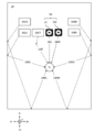
- FIG. 13 is an explanatory diagram of a usage space in which the directional speaker of the first modification is arranged.
- the three-dimensional coordinates are represented by the coordinate system in the used space SP.
- the directional speaker 30 is arranged at the speaker position POSs (xs, ys, zs).
- the listener TL exists at the target position POSt (xt, yt, zt).
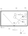
- FIG. 14 is an explanatory diagram of a first example of the operation of the directional speaker of the modified example 1.
- the path PA1 of the first example of the operation of the directional speaker 30 of the modification 1 is a path that reaches the target position POSt after the ultrasonic beam emitted from the directional speaker 30 is reflected by any of the reflecting members RM1 to RM4.
- FIG. 14 shows an example in which ultrasonic waves are reflected by the reflecting member RM3.
- the listener TL perceives a sound image at the reflection position POSr (xr, yr, zr). That is, the listener TL sounds as if an audible sound is sounding at the reflection position POSr (xr, yr, zr).
- FIG. 15 is an explanatory diagram of a second example of the operation of the directional speaker of the first modification.
- the path PA2 of the second example of the operation of the directional speaker 30 of the modification 1 is different from the target position POSt after the ultrasonic beam emitted from the directional speaker 30 is reflected by any of the reflecting members RM1 to RM4. It is a path that goes in the direction.
- FIG. 15 shows an example in which ultrasonic waves are reflected by the reflecting member RM3.
- the listener TL perceives a sound image at the reflection position POSr (xr, yr, zr). That is, the listener TL sounds as if an audible sound is sounding at the reflection position POSr (xr, yr, zr).
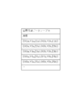
- FIG. 16 is a diagram showing a data structure of the spatial information data table of the first modification.
- the spatial information data table of FIG. 16 is stored in, for example, the storage device 11.
- Spatial information is stored in the spatial information data table.
- the spatial information is three-dimensional layout information relating to the three-dimensional layout of the used space SP.
- the spatial information data table includes a "coordinates" field. Each field is associated with each other.
- Coordinate information is stored in the "coordinates" field.
- the coordinate information represents, for example, three-dimensional coordinates that define a region (for example, a start point and an end point) of a reflective member existing in the used space SP.
- the coordinate information is represented by, for example, a used space coordinate system whose origin is an arbitrary position in the used space SP (for example, the point Po (0, 0, 0) in FIG. 3).
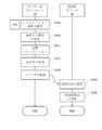
- FIG. 17 is a sequence diagram of the audio reproduction processing of the first modification.
- FIG. 18 is a detailed flowchart of the spatial simulation of FIG.
- FIG. 19 is a diagram showing an example of a screen displayed in the information processing of FIG.
- the audio controller 10 executes the acquisition of simulation conditions (S310). Specifically, the processor 12 displays the screen P30 (FIG. 19) on the display.
- the screen P30 includes the operation object B30 and the field objects F30a to F30d.
- the field objects F30a to F30d receive user instructions for designating simulation conditions.
- the field object F30a is an object that receives a user instruction for designating the coordinates (an example of "speaker position information") of the position of the directional speaker 30 (hereinafter referred to as "speaker position") Ps.
- the field object F30b is an object that receives a user instruction for designating the coordinates (an example of "target position information") of the position (hereinafter referred to as "target position”) Pt of the listener TL.
- the field object F30c is an object that accepts a user instruction for designating the direction Psi of the sound image SI (hereinafter referred to as “sound image direction”).
- the field object F30d is an object that receives a user instruction for designating the volume.
- the operation object B30 is an object that receives a user instruction for starting sound reproduction by the directional speaker 30.
- the user inputs the coordinates of the speaker position POSs in the field object F30a, inputs the coordinates of the target position POSt in the field object F30b, inputs the target sound image direction in the field object F30c, and inputs the desired volume in the field object F30d.
- the processor 12 stores the information (coordinates of speaker position POSs, coordinates of target position POSt, target sound image direction information, and volume information) input to the field objects F30a to F30d. Store in 11.
- step S310 the audio controller 10 executes the acquisition of the voice input signal (S210) in the same manner as in the present embodiment (FIG. 8).
- step S210 the audio controller 10 executes the spatial simulation (S311) according to the flowchart of FIG.
- the audio controller 10 executes the identification of the used space (S3110). Specifically, the processor 12 specifies the three-dimensional structure of the used space SP with reference to the spatial information data table (FIG. 16) stored in the storage device 11.
- the three-dimensional structure includes, for example, the following. ⁇ Three-dimensional size ⁇ Position of reflective member RM
- the audio controller 10 executes the calculation of the sound pressure distribution (S3111).
- the storage device 11 stores the spatial transmission model.
- the space transmission model is a system in which the correlation between the radiated sound pressure Vout, the three-dimensional structure of the used space SP, the speaker position Ps, the target position Pt, and the sound pressure distribution for each path formed in the used space SP is defined. It is a function.
- the processor 12 gives the spatial information obtained in step S3110 and the information (speaker position information and target position information) obtained in S310 to the spatial transmission model, so that the radiated sound pressure Vout and the path are combined. Calculate the distribution of sound pressure.
- the audio controller 10 executes path selection (S3112).
- the storage device 11 stores a sound image perception model.
- the sound image perception model defines the correlation between the distribution of sound pressure and the direction of the sound image SI perceived by the listener TL (hereinafter referred to as "perceived sound image direction").
- the processor 12 calculates the radiated sound pressure Vout and the perceived sound image direction for each pass by giving the distribution of the sound pressure for each combination of the radiated sound pressure Vout and the path obtained in step S3111 to the sound image perception model.
- the processor 12 compares the calculation result (perceived sound image direction) with the sound image direction corresponding to the user instruction obtained in step S310 (hereinafter referred to as “instructed sound image direction”), and thereby, the perception corresponding to the indicated sound image direction. Select the radiated sound pressure Vout and path corresponding to the sound image direction.
- the "perceived sound image direction corresponding to the indicated sound image direction” is, for example, at least one of the following. -Perceived sound image direction that matches the indicated sound image direction-Perceived sound image direction included in a predetermined range with reference to the indicated sound image direction
- step S3112 the audio controller 10 executes audio signal processing (S211) in the same manner as in the present embodiment (FIG. 8).
- the audio controller 10 executes speaker control (S312).
- the processor 12 corresponds to the selected path by referring to the combination of the radiated sound pressure (hereinafter referred to as “selected radiated sound pressure”) Vout and the path (hereinafter referred to as “selected path”) obtained in step S3112. Determine the radiation angle ⁇ to be used.
- the processor 12 generates a speaker control signal for emitting an ultrasonic beam at the selective radiation sound pressure Vout obtained in step S3112 in the direction of the determined radiation angle ⁇ .
- the processor 12 supplies the generated speaker control signal to the directional speaker 30.
- the directional speaker 30 performs a radiation direction change (S330). Specifically, the drive unit 32 generates a mechanism drive signal for reproducing the radiation angle ⁇ corresponding to the speaker control signal transmitted from the audio controller 10. The direction changing mechanism 36 changes the direction of the radiation surface to a direction corresponding to the radiation angle ⁇ according to the mechanism drive signal generated by the drive unit 32.
- step S330 the directional speaker 30 executes radiation of directional sound waves (S230) in the same manner as in the present embodiment (FIG. 8).
- the ultrasonic beam emitted in step S230 travels along the selection path.
- a virtual sound source is formed on the path.
- This virtual sound source forms the distribution of the sound pressure obtained in S3111 in the used space SP.
- the sound image can be localized in the desired sound image direction with respect to the listener TL.
- the audio controller 10 determines the first equalizer coefficient and the second equalizer coefficient so as to balance the desired volume, localization feeling, and surround feeling of the listener TL.
- Modification 2 is an example of a directional speaker capable of focusing an ultrasonic beam at an arbitrary focal point.
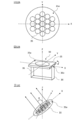
- FIG. 20 is a schematic view showing the configuration of the directional speaker of the second modification.
- an oscillator array FA including a plurality of ultrasonic oscillators 35 is arranged on the radiation surface of the directional speaker 30.
- the plurality of ultrasonic transducers 35 are arranged on the XY plane (hereinafter referred to as "array plane").
- the drive unit 32 generates an oscillator drive signal for individually driving each ultrasonic oscillator 35.
- the ultrasonic waves radiated from each ultrasonic oscillator 35 propagate in space and are focused at a focal point in space. Focused ultrasonic waves form a virtual sound source of audible sound at a focal point in space.
- FIG. 21 is an explanatory diagram of an operation example 1 of the directional speaker of the modification 2.
- the directional speaker 30 of the operation example 1 emits an ultrasonic wave USW1 having at least one of an oscillation phase difference and an oscillation amplitude difference.
- the ultrasonic wave USW1 is focused at the focal length FP1 which is separated from the center of the oscillator array FA by the focal length d1.
- the directional speaker 30 forms a point sound source at the focal point FP1.
- the focal point FP1 is located near the ear of the listener TL
- the point sound source is formed at the ear of the listener TL.
- the listener TL can hear the audible sound from the point sound source.
- FIG. 22 is an explanatory diagram of an operation example 2 of the directional speaker of the modification 2.
- ultrasonic waves USW2a and USW2b having an oscillation phase difference according to the time difference of vibration are radiated from the directional speaker 30 of the operation example 2.
- the ultrasonic wave USW2a is focused at the focal length FP2a separated from the center of the oscillator array FA by the focal length d2a.
- the ultrasonic wave USW2b is focused at the focal length FP2b separated by the focal length d2b from the center of the oscillator array FA.
- the directional speaker 30 forms a point sound source at the focal points FP2a and FP2b, respectively.
- the focal point FP2a when the focal point FP2a is located near the ear of the listener TL1, the point sound source formed by the focal point FP2a is formed at the ear of the listener TL1.
- the focal point FP2b is located near the ear of the listener TL2, the point sound source formed at the focal point FP2b is formed at the ear of the listener TL2.
- the listener TL1 can hear the audible sound from the point sound source formed at the focal point FP2a.
- the listener TL2 can hear the audible sound from the point sound source formed in the focal point FP2b.
- the directional speaker 30 can also form point sound sources at three or more focal points.
- FIG. 23 is a sequence diagram of the audio reproduction processing of the second modification.
- FIG. 24 is a detailed flowchart of the spatial simulation of FIG. 23.
- FIG. 25 is a detailed flowchart of the audio signal processing of FIG. 23.
- FIG. 26 is an explanatory diagram of the calculation of the phase difference of FIG.
- the audio controller 10 executes simulation condition acquisition (S310), voice input signal acquisition (S210), and so on, as in the modification 1 (FIG. 17).
- step S210 the audio controller 10 executes the spatial simulation (S410) according to the flow of FIG. 24.
- the audio controller 10 executes the specification of the usage space (S3110) in the same manner as in the modification 1 (FIG. 18).
- the audio controller 10 executes the calculation of the sound pressure distribution (S4100).
- the storage device 11 stores the spatial transmission model.
- the spatial transmission model the correlation between the radiated sound pressure Vout, the three-dimensional structure of the used space SP, the speaker position Ps, the target position Pt, and the sound pressure distribution for each focal position formed in the used space SP is defined. It is a system function.
- the processor 12 gives the spatial information obtained in step S3110 and the information (speaker position information and target position information) obtained in S310 to the spatial transmission model for each combination of radiated sound pressure Vout and focal position. Calculate the sound pressure distribution of.
- the determination of the focal position (S4101) is executed.
- the storage device 11 stores a sound image perception model.
- the sound image perception model the distribution of sound pressure and the correlation of the perceived sound image direction are defined.
- the processor 12 calculates the radiated sound pressure Vout and the perceived sound image direction for each focal position by giving the sound pressure distribution for each combination of the radiated sound pressure Vout and the focal position obtained in step S3111 to the sound image perception model.
- the storage device 11 indicates the position of the ultrasonic vibrator 35 (n) on the vibrator array FA with respect to the reference point (for example, the center) of the vibrator array FA composed of a plurality of ultrasonic vibrators 35.
- the coordinates (x (n), y (n), z (n)) of the sound oscillator 35 (n) are stored.
- n is an identifier (positive integer) of the ultrasonic oscillator 35.
- the focal coordinates (xfp, yfp, zfp) of the focal FP are selected.
- the "perceived sound image direction corresponding to the indicated sound image direction" is, for example, at least one of the following. -Perceived sound image direction that matches the indicated sound image direction-Perceived sound image direction included in a predetermined range with reference to the indicated sound image direction
- step S4100 the audio controller 10 executes audio signal processing (S411) according to the flow of FIG. 25.
- the audio controller 10 includes directional speaker equalizing (S2110), omnidirectional speaker equalizing with respect to the directional speaker channel (S2111), and omnidirectional with respect to the omnidirectional speaker channel. Equalizing the sex speaker (S2112) is performed.
- the audio controller 10 executes the phase difference calculation (S4110).
- the processor 12 has the coordinates (x (n), y (n), z (n)) of the ultrasonic oscillator 35 (n) stored in the storage device 11 and the focal coordinates (xfp, yfp). , Zfp), and the distance r (n) between the ultrasonic transducer 35 (n) and the focal point FP is calculated.
- the processor 12 has a time difference between the drive timing of the n + 1st driven ultrasonic vibrator 35 (n + 1) and the drive timing of the nth driven ultrasonic vibrator 35 (n) (hereinafter referred to as “driving time difference”).
- ⁇ T (n + 1) is calculated using Equation 1.
- ⁇ T (n + 1) ⁇ r (n + 1) / c... (Equation 1)
- ⁇ C Speed of sound
- the processor 12 uses the focal coordinates (xfp, yfp, zfp) and the coordinates (x (n + 1), y (n + 1), z (n + 1)) stored in the storage device 11, respectively.
- the drive time difference ⁇ T (n + 1) of the ultrasonic transducer 35 (n + 1) is calculated.
- the drive time difference ⁇ T (n + 1) is an example of the phase difference of ultrasonic waves radiated from the directional speaker 30.
- the processor 12 generates a drive time difference signal indicating the drive time difference ⁇ T (n + 1) of each ultrasonic oscillator 35 (n + 1).
- step S4110 the speaker control signal generation (S2113) is executed in the same manner as in the present embodiment (FIG. 9).
- the audio controller 10 executes speaker control (S412). Specifically, the processor 12 identifies the speaker control signals (directional speaker control signal, front speaker control signal, and woofer control signal) obtained in step S411 by the speaker identification information corresponding to each channel signal. It is transmitted to the speakers (front speaker LC, woofer SW, up-firing directional speaker 30CT, side firing directional speakers 30LS and 30RS, and back-firing directional speakers 30LB and 30RB). The processor 12 transmits the drive time difference signal obtained in S4110 to the directional speaker 30.
- the speaker control signals directional speaker control signal, front speaker control signal, and woofer control signal
- the processor 12 transmits the drive time difference signal obtained in S4110 to the directional speaker 30.
- the directional speaker 30 executes radiation of directional sound waves (S430).
- the drive unit 32 generates an oscillator drive signal for radiating ultrasonic waves corresponding to the directional speaker control signal transmitted from the audio controller 10.
- a voltage is applied to each ultrasonic oscillator 35 according to the oscillator drive signal generated by the drive unit 32, with a time difference corresponding to the drive time difference signal transmitted from the audio controller 10.
- Each ultrasonic oscillator 35 vibrates according to the applied voltage.
- ultrasonic waves with radiated sound pressure corresponding to the volume included in the setting information are emitted. This ultrasonic wave is focused at the focal point FP determined in step S4101.
- the ultrasonic waves focused by the focal point FP form a virtual sound source at the focal point.
- An audible sound is generated from this virtual sound source. That is, the directional speaker 30 can generate an audible sound at an arbitrary position.
- the directional speaker 30 can change the traveling range in which the audible sound wave travels by changing the focal position.
- the distribution of the audible range in which the listener L can hear the audible sound forms a substantially rotationally symmetric shape with the focal point FP as the axis.
- the audible range is defined by the combination of the direction or angle at which the audible sound travels with respect to the ultrasonic beam and the distance between the focal point FP and the listener L.
- the audible range is determined by the magnitude relationship between the environmental sound of the usage environment of the directional speaker 30 and the volume of the audible sound.
- the volume of the audible sound is determined by the amplitude or the degree of modulation of the ultrasonic waves radiated from the ultrasonic vibrator 35. Therefore, the processor 12 can change the audible range by adjusting the amplitude or the degree of modulation of the ultrasonic wave.
- the ultrasonic beam emitted in step S430 is focused at the focal point.
- a virtual sound source is formed at the focal point.
- This virtual sound source forms the distribution of the sound pressure obtained in S4100 in the used space SP.
- the sound image can be localized in the desired sound image direction with respect to the listener TL.
- Modification 3 is an example of applying frequency filtering to the audio input signal of the directional speaker channel.
- FIG. 27 is a detailed flowchart of the audio signal processing of the third modification.
- FIG. 28 is a schematic diagram of a frequency characteristic signal related to the audio signal processing of FIG. 27.
- the audio controller 10 executes the first frequency filtering (S5110).
- the storage device 11 stores a filtering model according to the output frequency characteristic of the directional speaker 30.
- the filtering model defines the volume and output frequency characteristics of the directional speaker 30, and the correlation between the filter coefficients.
- the processor 12 refers to the filtering model, and among the user instructions given to the field object F11c, the user instruction corresponding to the directional speaker 30 (that is, the volume of the directional speaker 30 specified by the user) and the directivity.
- the filter coefficient (hereinafter referred to as "first filter coefficient") FIL1 of the directional speaker 30 is determined according to the combination of the output frequency characteristics of the speaker 30.
- the first filter coefficient FIL1 is, for example, a coefficient for extracting a high frequency band (so-called high-pass filter).
- the processor 12 generates a first frequency characteristic signal from the audio input signal of the directional speaker channel by applying the first filter coefficient FIL1 to the audio input signal of the directional speaker channel.
- the audio controller 10 performs a second frequency filtering (S5111). Specifically, the processor 12 identifies a speaker (for example, a front speaker LC) that is suitable for output in a band that is not suitable for output from the directional speaker 30 among the omnidirectional speakers 40. The processor 12 determines the filter coefficient (hereinafter referred to as “second filter coefficient”) FIL2 of the omnidirectional speaker 40 with respect to the directional speaker channel with reference to the first filter coefficient FIL1 obtained in step S5110. The second filter coefficient FIL2 is different from the first filter coefficient FIL1. The second filter coefficient FIL2 is, for example, a coefficient for extracting a low frequency band as compared with the first filter coefficient FIL1 (so-called low-pass filter). The processor 12 generates a second frequency characteristic signal from the audio input signal of the directional speaker channel by applying the second filter coefficient FIL2 to the audio input signal of the directional speaker channel.
- a speaker for example, a front speaker LC
- the processor 12 determines the filter coefficient (her
- step S5111 the audio controller 10 executes the generation of the speaker control signal (S2113) in the same manner as in the present embodiment (FIG. 9).
- the same effect as that of the present embodiment can be obtained without executing equalizing.
- the fourth modification is an example in which the second frequency characteristic signal is adjusted when a predetermined condition is satisfied after the second frequency characteristic signal is generated.
- the first example of Modified Example 4 will be described.
- the first example of the modification 4 is an example of adjusting the second frequency characteristic signal when the second frequency characteristic signal satisfies the condition that adversely affects the sense of localization or the sense of surround.
- step S2111 the processor 12 of the first example of the modified example 4 has a second frequency characteristic so that when the peak of the second frequency characteristic signal is equal to or more than a predetermined threshold value, the peak becomes less than the threshold value. Adjust the signal.
- step S2113 the processor 12 generates a speaker control signal for the omnidirectional speaker 40 based on the adjusted second frequency characteristic signal.
- the second example of the modification 4 is an example of adjusting the second frequency characteristic signal when the relationship between the first frequency characteristic signal and the second frequency characteristic signal satisfies a predetermined condition.
- the processor 12 of the second example of the modification 4 when the peak of the second frequency characteristic signal is larger than the peak of the first frequency characteristic signal in step S2111 (FIG. 9), the peak of the second frequency characteristic signal is the first frequency.
- the second frequency characteristic signal is adjusted so that it is smaller than the peak of the characteristic signal.
- the processor 12 generates a speaker control signal for the omnidirectional speaker 40 based on the adjusted second frequency characteristic signal.
- the second frequency characteristic signal when the second frequency characteristic signal satisfies the condition that adversely affects the localization feeling or the surround feeling, the second frequency characteristic signal is adjusted. Thereby, the sense of localization or the sense of surround can be further improved.
- the first aspect of this embodiment is An audio controller 1010 that controls the directional speaker 30 and the omnidirectional speaker 40. Equipped with a means to acquire a multi-channel audio input signal A means for controlling the directional speaker 30 so as to output an audible sound corresponding to the first part of the directional speaker channel audio input signal among the multi-channel audio input signals is provided. A means for controlling the omnidirectional speaker 40 so as to output an audible sound corresponding to the second part of the audio input signal of the directional speaker channel is provided.
- the listening experience in the audio system using the directional speaker and the omnidirectional speaker is compared with the case where the audible sound corresponding to the directional speaker channel is output only from the directional speaker 30.
- the quality of the speaker can be improved.
- the second aspect of this embodiment is The means for controlling the directional speaker 30 treats a portion of the audio input signal of the directional speaker channel suitable for output from the directional speaker 30 as the first portion.
- the means for controlling the omnidirectional speaker 40 treats a portion of the audio input signal of the directional speaker channel that is not suitable for the output of the directional speaker channel as the second portion.
- the third aspect of this embodiment is The means for controlling the omnidirectional speaker 40 outputs the audible sound corresponding to the audio input signal of the omnidirectional speaker channel and the audible sound corresponding to the second portion among the multi-channel audio input signals. Controls the omnidirectional speaker 40, The audio controller 10.
- the fourth aspect of this embodiment is The means for controlling the directional speaker 30 is
- the audio input signal of the directional speaker channel is converted into the first frequency characteristic signal by using the first equalizer coefficient corresponding to the output frequency characteristic of the directional speaker 30.
- the directional speaker 30 is controlled so as to output the audible sound corresponding to the first frequency characteristic signal.
- the means for controlling the omnidirectional speaker 40 is Using the second equalizer coefficient, which is different from the first equalizer coefficient, the audio input signal of the directional speaker channel is converted into the second frequency characteristic signal.
- the omnidirectional speaker 40 is controlled so as to output an audible sound corresponding to the second frequency characteristic signal.
- a fifth aspect of this embodiment is The means for controlling the directional speaker 30 determines the first equalizer coefficient according to the combination of the output frequency characteristic of the directional speaker 30 and the volume output from the directional speaker 30.
- the sixth aspect of this embodiment is The means for controlling the directional speaker 30 is
- the first frequency characteristic signal is extracted from the audio input signal of the directional speaker channel by using the first filter coefficient corresponding to the output frequency characteristic of the directional speaker 30.
- the directional speaker 30 is controlled so as to output the audible sound corresponding to the first frequency characteristic signal.
- the means for controlling the omnidirectional speaker 40 is A second frequency characteristic signal is extracted from the audio input signal of the directional speaker channel using a second filter coefficient different from the first filter coefficient.
- the omnidirectional speaker 40 is controlled so as to output an audible sound corresponding to the second frequency characteristic signal.
- the surround environment desired by the user can be constructed without using the equalizer.
- the seventh aspect of this embodiment is The directional speaker 30 emits an ultrasonic beam reflected by a reflecting member existing in the space where the directional speaker 30 is used.
- the sound image can be localized in the desired sound image direction with respect to the listener TL.
- the eighth aspect of this embodiment is A means for specifying a three-dimensional layout of the space in which the directional speaker 30 is used is provided.
- a means for identifying the position of the directional speaker 30 in the usage space is provided. Equipped with a means to locate the listener in the space of use
- the sound image can be localized in the desired sound image direction with respect to the listener TL.
- the ninth aspect of this embodiment is A means for specifying a three-dimensional layout of the space in which the directional speaker 30 is used is provided.
- a means for identifying the position of the directional speaker 30 in the usage space is provided. Equipped with a means to locate the listener in the space of use
- the sound image can be localized in the desired sound image direction with respect to the listener TL.
- the tenth aspect of this embodiment is When the second frequency characteristic signal satisfies a predetermined condition, the second frequency characteristic signal is adjusted.
- the feeling of localization or surround sound can be further improved.
- the eleventh aspect of this embodiment is When the peak of the second frequency characteristic signal is equal to or higher than a predetermined threshold value, the second frequency characteristic signal is adjusted.
- the feeling of localization or surround sound can be further improved.
- the twelfth aspect of this embodiment is When the relationship between the first frequency characteristic signal and the second frequency characteristic signal satisfies a predetermined condition, the second frequency characteristic signal is adjusted.
- the feeling of localization or surround sound can be further improved.
- the thirteenth aspect of this embodiment is
- the audio system 1 includes a plurality of directional speakers 30, at least one omnidirectional speaker 40, and an audio controller 10.
- the fourteenth aspect of this embodiment is The plurality of directional speakers 30 are arranged in front of the listener and in different radial directions from each other. Audio system 1.
- the quality of the listening experience can be further improved.
- the fifteenth aspect of this embodiment is At least one of the plurality of directional speakers 30 is arranged so that the radial surface faces the top of the listener. Audio system 1.
- the quality of the listening experience can be further improved.
- the sixteenth aspect of this embodiment is The plurality of directional speakers 30 are arranged at a position higher than the head of the listener TL, and the radiation surfaces are arranged so as to face different directions from each other. Audio system 1.
- the 16th aspect it is possible to provide the listener TL with a stereophonic experience by combining directional sound waves and omnidirectional sound waves.
- the seventeenth aspect of this embodiment is The plurality of directional speakers 30 are arranged on the ceiling of the usage space SP in which the directional speakers 30 are used. Audio system 1.
- the listener TL with a stereophonic experience by combining directional sound waves and omnidirectional sound waves.
- the eighteenth aspect of this embodiment is The omnidirectional speaker 40 is arranged so that the radiation surface of the omnidirectional speaker 40 faces a direction different from the radiation surface of each directional speaker 30. Audio system 1.
- the eighteenth aspect it is possible to provide the listener TL with a stereophonic experience by combining directional sound waves and omnidirectional sound waves.
- the nineteenth aspect of this embodiment is It is a program for making a computer (for example, an audio controller 10) function as each means of any one of the above-mentioned aspects.
- a twentieth aspect of this embodiment is An audio control method for controlling a directional speaker 30 and an omnidirectional speaker 40.
- steps to get multi-channel audio input signal A step of controlling the directional speaker 30 so as to output an audible sound corresponding to the first part of the directional speaker channel audio input signal among the multi-channel audio input signals is provided.
- a step of controlling the omnidirectional speaker 40 so as to output an audible sound corresponding to the second part of the audio input signal of the directional speaker channel is provided. This is an audio control method.
- FIG. 3 shows an example of five directional speakers 30, the scope of application of this embodiment is not limited to this. This embodiment can be applied to an audio system 1 including two or more directional speakers 30.
- FIG. 3 shows an example in which one directional speaker 30 (up-firing directional speaker 30CT) is assigned to the speaker position “upward filing”, but the present embodiment is not limited to this.
- the present embodiment is also applicable when a plurality of directional speakers 30 are assigned to the speaker position "upward filing". For example, in the configuration of FIG. 1, when two directional speakers 30 are assigned to the speaker position "upward filing", a 7.1.2 channel surround system is realized. For example, in the configuration of FIG. 1, when four directional speakers 30 are assigned to the speaker position "upward filing", a 7.1.4 channel surround system is realized.
- This embodiment can be applied to a surround system of an arbitrary number of channels (for example, 5.1 channel, 5.1.1 channel, 7.1 channel, or 7.1.1 channel).
- FIG. 7 shows an example in which the distance of each speaker is input to the user
- the scope of the present embodiment is not limited to this.
- the present embodiment is also applicable to the case where the distance of each speaker is detected by using a sensor (for example, an infrared sensor or an image sensor).
- a sensor for example, an infrared sensor or an image sensor.
- the second audible sound is output from the front speaker LC
- the scope of application of the present embodiment is not limited to this.
- the second audible sound is transmitted to a plurality of omnidirectional speakers 40 arranged in different directions with respect to the listener TL (for example, a front speaker LC arranged in front of the listener TL, and left and right of the listener TL. It is also applicable when outputting from a sound speaker arranged in. As a result, the sense of localization or surround sound of the listener TL can be improved.
- an example of an ultrasonic speaker is shown as an example of the directional speaker 30, but the scope of the present embodiment is not limited to this.
- This embodiment can also be applied to a directional speaker 30 using a method other than the ultrasonic speaker.
- the directional speaker 30 using a method other than the ultrasonic speaker includes, for example, the following.
- a directional speaker 30 including a speaker array composed of a plurality of speakers.
- a directional speaker 30 provided with a flat diaphragm.
- the second audible sound and the audible sound corresponding to the audio input signal of the omnidirectional speaker channel are output from the omnidirectional speaker 40
- the scope of the present embodiment is limited to this. I can't.
- only the second audible sound is output from the specific omnidirectional speaker 40 (that is, the omnidirectional speaker 40 that outputs the second audible sound and the audio input signal of the omnidirectional speaker channel are supported. It is also applicable to the case of distinguishing from the omnidirectional speaker 40 that outputs audible sound).
- the first equalizer coefficient and the second equalizer coefficient are determined with reference to a playback mode specified by the user (for example, a parameter set composed of a combination of volume balances of each speaker set in advance). Is also good.
- the first filter coefficient and the second filter coefficient are determined with reference to a playback mode specified by the user (for example, a parameter set composed of a combination of volume balances of each speaker set in advance). Is also good.
- the position of the directional speaker 30 is not limited to the example of the present embodiment.
- the present embodiment is also applicable to an example in which the directional speaker 30 is arranged in at least one of the following. -Ceiling (that is, higher than the head of the listener TL, for example, the ceiling lighting socket) -Wall (for example, listener TL ear height)
- -Ceiling that is, higher than the head of the listener TL, for example, the ceiling lighting socket
- -Wall for example, listener TL ear height
- the radiation surface of the omnidirectional speaker 40 faces a direction different from the radiation surface of the directional speaker 30.
- the directional sound wave radiated from the directional speaker 30 is reflected by the reflecting member (for example, the ceiling, the wall, and the floor) and propagates so as to surround the listener TL. This makes it possible to provide the listener TL with a stereophonic experience by combining directional sound waves and omnidirectional sound waves.
- the speaker position supported by the directional speaker channel is not limited to the example of this embodiment.
- the directional speaker channel of the present embodiment is not particularly limited as long as it is a speaker position in which high-band sound should be output.
- the directional speaker channel may correspond to the speaker position of the front speaker.
- Audio system 10 Audio controller 11: Storage device 12: Processor 13: Input / output interface 14: Communication interface 30: Directional speaker 30CT: Up-firing directional speaker 30LB: Back-firing directional speaker 30LS: Side firing Directional speaker 30RB: Back firing directional speaker 30RS: Side firing directional speaker 32: Drive unit 34: Communication interface 35: Ultrasonic transducer 35a: Radiation surface 36: Direction change mechanism 36a: Support point 40: Omnidirectional Sex speaker
Landscapes
- Physics & Mathematics (AREA)
- Engineering & Computer Science (AREA)
- Acoustics & Sound (AREA)
- Signal Processing (AREA)
- Health & Medical Sciences (AREA)
- General Health & Medical Sciences (AREA)
- Otolaryngology (AREA)
- Circuit For Audible Band Transducer (AREA)
- Stereophonic System (AREA)
Abstract
Ce dispositif de commande audio permettant de commander un haut-parleur directionnel et un haut-parleur non directionnel comporte : un moyen pour acquérir de signaux d'entrée audio multicanaux ; un moyen pour commander un haut-parleur directionnel de façon à délivrer en sortie un son audible correspondant à une première partie d'un signal d'entrée audio pour un canal de haut-parleur directionnel dans les signaux d'entrée audio multicanaux ; et un moyen pour commander un haut-parleur non directionnel de façon à délivrer en sortie un son audible correspondant à une seconde partie du signal d'entrée audio pour le canal de haut-parleur directionnel.
Priority Applications (1)
| Application Number | Priority Date | Filing Date | Title |
|---|---|---|---|
| JP2021537638A JP7317396B2 (ja) | 2019-08-05 | 2020-07-10 | オーディオコントローラ、オーディオシステム、プログラム、及び、オーディオ制御方法 |
Applications Claiming Priority (2)
| Application Number | Priority Date | Filing Date | Title |
|---|---|---|---|
| JP2019-143769 | 2019-08-05 | ||
| JP2019143769 | 2019-08-05 |
Publications (1)
| Publication Number | Publication Date |
|---|---|
| WO2021024692A1 true WO2021024692A1 (fr) | 2021-02-11 |
Family
ID=74502962
Family Applications (1)
| Application Number | Title | Priority Date | Filing Date |
|---|---|---|---|
| PCT/JP2020/026939 WO2021024692A1 (fr) | 2019-08-05 | 2020-07-10 | Dispositif de commande audio, système audio, programme, et procédé de commande audio |
Country Status (2)
| Country | Link |
|---|---|
| JP (1) | JP7317396B2 (fr) |
| WO (1) | WO2021024692A1 (fr) |
Citations (3)
| Publication number | Priority date | Publication date | Assignee | Title |
|---|---|---|---|---|
| JPS5825796A (ja) * | 1981-08-10 | 1983-02-16 | Victor Co Of Japan Ltd | 可変指向性スピ−カシステム |
| JP2008035133A (ja) * | 2006-07-27 | 2008-02-14 | Kenwood Corp | オーディオ装置及びスピーカ装置 |
| WO2019069743A1 (fr) * | 2017-10-03 | 2019-04-11 | ピクシーダストテクノロジーズ株式会社 | Dispositif de commande audio, haut-parleur à ultrasons et système audio |
Family Cites Families (5)
| Publication number | Priority date | Publication date | Assignee | Title |
|---|---|---|---|---|
| US8139797B2 (en) | 2002-12-03 | 2012-03-20 | Bose Corporation | Directional electroacoustical transducing |
| JP4114583B2 (ja) | 2003-09-25 | 2008-07-09 | ヤマハ株式会社 | 特性補正システム |
| US8750543B2 (en) | 2010-09-08 | 2014-06-10 | Panasonic Corporation | Sound reproduction device |
| JP6287203B2 (ja) | 2013-12-27 | 2018-03-07 | ヤマハ株式会社 | スピーカ装置 |
| JP6329679B1 (ja) | 2017-10-03 | 2018-05-23 | ピクシーダストテクノロジーズ株式会社 | オーディオコントローラ、超音波スピーカ、オーディオシステム、及びプログラム |
-
2020
- 2020-07-10 JP JP2021537638A patent/JP7317396B2/ja active Active
- 2020-07-10 WO PCT/JP2020/026939 patent/WO2021024692A1/fr active Application Filing
Patent Citations (3)
| Publication number | Priority date | Publication date | Assignee | Title |
|---|---|---|---|---|
| JPS5825796A (ja) * | 1981-08-10 | 1983-02-16 | Victor Co Of Japan Ltd | 可変指向性スピ−カシステム |
| JP2008035133A (ja) * | 2006-07-27 | 2008-02-14 | Kenwood Corp | オーディオ装置及びスピーカ装置 |
| WO2019069743A1 (fr) * | 2017-10-03 | 2019-04-11 | ピクシーダストテクノロジーズ株式会社 | Dispositif de commande audio, haut-parleur à ultrasons et système audio |
Also Published As
| Publication number | Publication date |
|---|---|
| JP7317396B2 (ja) | 2023-07-31 |
| JPWO2021024692A1 (fr) | 2021-02-11 |
Similar Documents
| Publication | Publication Date | Title |
|---|---|---|
| TWI247550B (en) | Loudspeaker, loudspeaker system and method of directing sound waves from a driver of a loudspeaker | |
| US5764777A (en) | Four dimensional acoustical audio system | |
| JP7271695B2 (ja) | ハイブリッドスピーカ及びコンバータ | |
| JP2013529004A (ja) | 位置追跡を備えるスピーカ | |
| KR20030003694A (ko) | 3차원 음향의 최적화 시스템 및 방법 | |
| KR20070040762A (ko) | 초지향성 음향 시스템 및 프로젝터 | |
| EP2189009A1 (fr) | Système de reproduction audio comprenant des haut-parleurs à directivité étroite et large | |
| WO2019069743A1 (fr) | Dispositif de commande audio, haut-parleur à ultrasons et système audio | |
| US10271133B2 (en) | Acoustic lens system | |
| JP2006509439A (ja) | パーソナライズされたサラウンドサウンドヘッドホンシステム | |
| JP6329679B1 (ja) | オーディオコントローラ、超音波スピーカ、オーディオシステム、及びプログラム | |
| KR102388361B1 (ko) | 입체 영상 재생 방법, 입체 음향 재생 방법, 입체 영상 재생 시스템 및 입체 음향 재생 시스템 | |
| WO2021024692A1 (fr) | Dispositif de commande audio, système audio, programme, et procédé de commande audio | |
| WO2021002191A1 (fr) | Contrôleur audio, système audio, programme et procédé de commande d'une pluralité de haut-parleurs directifs | |
| JP5988710B2 (ja) | 音響システム及び音響特性制御装置 | |
| JP6330098B1 (ja) | オーディオコントローラ、プログラム、超音波スピーカ、音源装置 | |
| JP7095863B2 (ja) | 音響システム、音響処理方法、及びプログラム | |
| WO2020004460A1 (fr) | Dispositif de commande à ultrasons, haut-parleur à ultrasons, et programme | |
| JP2021177607A (ja) | オーディオコントローラ、プログラム、及び、パラメトリックスピーカの制御方法 | |
| JP2019068396A (ja) | オーディオコントローラ、プログラム、超音波スピーカ、音源装置 | |
| WO2021002162A1 (fr) | Dispositif de commande audio, programme, haut-parleur directionnel et procédé de commande de haut-parleur directionnel | |
| CN112689225B (zh) | 一种声学装置和音频系统 | |
| WO2007096792A1 (fr) | Dispositif et procede de traitement de donnees audio | |
| JP2021145236A (ja) | オーディオコントローラおよびオーディオ制御プログラム | |
| JP2021180470A (ja) | 指向性スピーカ、音響システム、及び、プログラム |
Legal Events
| Date | Code | Title | Description |
|---|---|---|---|
| 121 | Ep: the epo has been informed by wipo that ep was designated in this application |
Ref document number: 20850676 Country of ref document: EP Kind code of ref document: A1 |
|
| WWE | Wipo information: entry into national phase |
Ref document number: 2021537638 Country of ref document: JP |
|
| NENP | Non-entry into the national phase |
Ref country code: DE |
|
| 122 | Ep: pct application non-entry in european phase |
Ref document number: 20850676 Country of ref document: EP Kind code of ref document: A1 |