WO2021024631A1 - 電池 - Google Patents
電池 Download PDFInfo
- Publication number
- WO2021024631A1 WO2021024631A1 PCT/JP2020/024537 JP2020024537W WO2021024631A1 WO 2021024631 A1 WO2021024631 A1 WO 2021024631A1 JP 2020024537 W JP2020024537 W JP 2020024537W WO 2021024631 A1 WO2021024631 A1 WO 2021024631A1
- Authority
- WO
- WIPO (PCT)
- Prior art keywords
- current collector
- negative electrode
- positive electrode
- electrode current
- plate
- Prior art date
Links
Images


Classifications
-
- H—ELECTRICITY
- H01—ELECTRIC ELEMENTS
- H01M—PROCESSES OR MEANS, e.g. BATTERIES, FOR THE DIRECT CONVERSION OF CHEMICAL ENERGY INTO ELECTRICAL ENERGY
- H01M50/00—Constructional details or processes of manufacture of the non-active parts of electrochemical cells other than fuel cells, e.g. hybrid cells
- H01M50/10—Primary casings, jackets or wrappings of a single cell or a single battery
- H01M50/183—Sealing members
- H01M50/186—Sealing members characterised by the disposition of the sealing members
- H01M50/188—Sealing members characterised by the disposition of the sealing members the sealing members being arranged between the lid and terminal
-
- H—ELECTRICITY
- H01—ELECTRIC ELEMENTS
- H01M—PROCESSES OR MEANS, e.g. BATTERIES, FOR THE DIRECT CONVERSION OF CHEMICAL ENERGY INTO ELECTRICAL ENERGY
- H01M50/00—Constructional details or processes of manufacture of the non-active parts of electrochemical cells other than fuel cells, e.g. hybrid cells
- H01M50/10—Primary casings, jackets or wrappings of a single cell or a single battery
- H01M50/172—Arrangements of electric connectors penetrating the casing
- H01M50/174—Arrangements of electric connectors penetrating the casing adapted for the shape of the cells
- H01M50/176—Arrangements of electric connectors penetrating the casing adapted for the shape of the cells for prismatic or rectangular cells
-
- H—ELECTRICITY
- H01—ELECTRIC ELEMENTS
- H01M—PROCESSES OR MEANS, e.g. BATTERIES, FOR THE DIRECT CONVERSION OF CHEMICAL ENERGY INTO ELECTRICAL ENERGY
- H01M4/00—Electrodes
- H01M4/02—Electrodes composed of, or comprising, active material
- H01M4/64—Carriers or collectors
- H01M4/70—Carriers or collectors characterised by shape or form
- H01M4/80—Porous plates, e.g. sintered carriers
-
- H—ELECTRICITY
- H01—ELECTRIC ELEMENTS
- H01M—PROCESSES OR MEANS, e.g. BATTERIES, FOR THE DIRECT CONVERSION OF CHEMICAL ENERGY INTO ELECTRICAL ENERGY
- H01M50/00—Constructional details or processes of manufacture of the non-active parts of electrochemical cells other than fuel cells, e.g. hybrid cells
- H01M50/10—Primary casings, jackets or wrappings of a single cell or a single battery
- H01M50/102—Primary casings, jackets or wrappings of a single cell or a single battery characterised by their shape or physical structure
- H01M50/103—Primary casings, jackets or wrappings of a single cell or a single battery characterised by their shape or physical structure prismatic or rectangular
-
- H—ELECTRICITY
- H01—ELECTRIC ELEMENTS
- H01M—PROCESSES OR MEANS, e.g. BATTERIES, FOR THE DIRECT CONVERSION OF CHEMICAL ENERGY INTO ELECTRICAL ENERGY
- H01M50/00—Constructional details or processes of manufacture of the non-active parts of electrochemical cells other than fuel cells, e.g. hybrid cells
- H01M50/10—Primary casings, jackets or wrappings of a single cell or a single battery
- H01M50/147—Lids or covers
- H01M50/148—Lids or covers characterised by their shape
- H01M50/15—Lids or covers characterised by their shape for prismatic or rectangular cells
-
- H—ELECTRICITY
- H01—ELECTRIC ELEMENTS
- H01M—PROCESSES OR MEANS, e.g. BATTERIES, FOR THE DIRECT CONVERSION OF CHEMICAL ENERGY INTO ELECTRICAL ENERGY
- H01M50/00—Constructional details or processes of manufacture of the non-active parts of electrochemical cells other than fuel cells, e.g. hybrid cells
- H01M50/10—Primary casings, jackets or wrappings of a single cell or a single battery
- H01M50/147—Lids or covers
- H01M50/166—Lids or covers characterised by the methods of assembling casings with lids
- H01M50/167—Lids or covers characterised by the methods of assembling casings with lids by crimping
-
- H—ELECTRICITY
- H01—ELECTRIC ELEMENTS
- H01M—PROCESSES OR MEANS, e.g. BATTERIES, FOR THE DIRECT CONVERSION OF CHEMICAL ENERGY INTO ELECTRICAL ENERGY
- H01M50/00—Constructional details or processes of manufacture of the non-active parts of electrochemical cells other than fuel cells, e.g. hybrid cells
- H01M50/10—Primary casings, jackets or wrappings of a single cell or a single battery
- H01M50/183—Sealing members
- H01M50/184—Sealing members characterised by their shape or structure
-
- H—ELECTRICITY
- H01—ELECTRIC ELEMENTS
- H01M—PROCESSES OR MEANS, e.g. BATTERIES, FOR THE DIRECT CONVERSION OF CHEMICAL ENERGY INTO ELECTRICAL ENERGY
- H01M50/00—Constructional details or processes of manufacture of the non-active parts of electrochemical cells other than fuel cells, e.g. hybrid cells
- H01M50/50—Current conducting connections for cells or batteries
- H01M50/502—Interconnectors for connecting terminals of adjacent batteries; Interconnectors for connecting cells outside a battery casing
-
- H—ELECTRICITY
- H01—ELECTRIC ELEMENTS
- H01M—PROCESSES OR MEANS, e.g. BATTERIES, FOR THE DIRECT CONVERSION OF CHEMICAL ENERGY INTO ELECTRICAL ENERGY
- H01M50/00—Constructional details or processes of manufacture of the non-active parts of electrochemical cells other than fuel cells, e.g. hybrid cells
- H01M50/50—Current conducting connections for cells or batteries
- H01M50/528—Fixed electrical connections, i.e. not intended for disconnection
-
- H—ELECTRICITY
- H01—ELECTRIC ELEMENTS
- H01M—PROCESSES OR MEANS, e.g. BATTERIES, FOR THE DIRECT CONVERSION OF CHEMICAL ENERGY INTO ELECTRICAL ENERGY
- H01M50/00—Constructional details or processes of manufacture of the non-active parts of electrochemical cells other than fuel cells, e.g. hybrid cells
- H01M50/50—Current conducting connections for cells or batteries
- H01M50/531—Electrode connections inside a battery casing
- H01M50/536—Electrode connections inside a battery casing characterised by the method of fixing the leads to the electrodes, e.g. by welding
-
- H—ELECTRICITY
- H01—ELECTRIC ELEMENTS
- H01M—PROCESSES OR MEANS, e.g. BATTERIES, FOR THE DIRECT CONVERSION OF CHEMICAL ENERGY INTO ELECTRICAL ENERGY
- H01M50/00—Constructional details or processes of manufacture of the non-active parts of electrochemical cells other than fuel cells, e.g. hybrid cells
- H01M50/50—Current conducting connections for cells or batteries
- H01M50/543—Terminals
- H01M50/547—Terminals characterised by the disposition of the terminals on the cells
- H01M50/55—Terminals characterised by the disposition of the terminals on the cells on the same side of the cell
-
- H—ELECTRICITY
- H01—ELECTRIC ELEMENTS
- H01M—PROCESSES OR MEANS, e.g. BATTERIES, FOR THE DIRECT CONVERSION OF CHEMICAL ENERGY INTO ELECTRICAL ENERGY
- H01M50/00—Constructional details or processes of manufacture of the non-active parts of electrochemical cells other than fuel cells, e.g. hybrid cells
- H01M50/50—Current conducting connections for cells or batteries
- H01M50/543—Terminals
- H01M50/552—Terminals characterised by their shape
- H01M50/553—Terminals adapted for prismatic, pouch or rectangular cells
- H01M50/555—Window-shaped terminals
-
- H—ELECTRICITY
- H01—ELECTRIC ELEMENTS
- H01M—PROCESSES OR MEANS, e.g. BATTERIES, FOR THE DIRECT CONVERSION OF CHEMICAL ENERGY INTO ELECTRICAL ENERGY
- H01M4/00—Electrodes
- H01M4/02—Electrodes composed of, or comprising, active material
- H01M2004/026—Electrodes composed of, or comprising, active material characterised by the polarity
- H01M2004/027—Negative electrodes
-
- H—ELECTRICITY
- H01—ELECTRIC ELEMENTS
- H01M—PROCESSES OR MEANS, e.g. BATTERIES, FOR THE DIRECT CONVERSION OF CHEMICAL ENERGY INTO ELECTRICAL ENERGY
- H01M4/00—Electrodes
- H01M4/02—Electrodes composed of, or comprising, active material
- H01M2004/026—Electrodes composed of, or comprising, active material characterised by the polarity
- H01M2004/028—Positive electrodes
Definitions
- the present invention relates to a battery.
- EV electric vehicles
- HEV hybrid electric vehicles
- PHEV hybrid electric vehicles
- applications for suppressing output fluctuations such as solar power generation and wind power generation
- system power for storing power at night and using it in the daytime
- batteries such as alkaline secondary batteries and non-aqueous electrolyte secondary batteries are used.
- Foreign matter may be mixed into the above battery during its assembly, etc.
- the mixed foreign matter is a metallic foreign matter
- an internal short circuit may be caused.
- the mechanism of the internal short circuit is as follows.
- the secondary battery is usually assembled in a clean room in order to prevent foreign substances such as metal foreign substances from entering the battery. Further, the metal foreign matter adhering to the electrode body during assembly is removed by air blowing, suction, magnetic force adsorption, wiping with a polishing tape, or the like.
- Patent Document 1 proposes a closed-type battery formed by inserting an electrode body into a bag-shaped porous body and inserting the porous body into which the electrode body is inserted into a closed container.
- the present invention has been made in view of this point, and an object of the present invention is to provide a battery capable of effectively suppressing the invasion of foreign matter into the electrode body without reducing the battery capacity. There is.
- the battery of the present invention has an electrode body in which a positive electrode plate and a negative electrode plate are laminated via a separator, an exterior body having an opening and accommodating the electrode body, a sealing plate for sealing the opening, and the sealing.
- the outside is provided with an external terminal attached to the plate, and a tab portion provided on at least one of the positive electrode plate and the negative electrode plate is provided via a current collector arranged between the electrode body and the sealing plate. It is electrically connected to the terminal, and the current collector has a first current collector and a second current collector, and the first current collector and the second current collector are welded to each other. At the same time, the welded portion is covered with a covering member.
- the first current collector has a recess, the first current collector and the second current collector are overlapped and welded in the recess, and the covering member covers the recess. You may be.
- a thin-walled portion is provided in the recess, and the first current collector may be through-welded to the second current collector in the thin-walled portion.
- the covering member may enter the recess formed by the recess.
- the battery of the present invention includes an electrode body in which a positive electrode plate and a negative electrode plate are laminated via a separator, an exterior body having an opening and accommodating the electrode body, and a sealing plate for sealing the opening.
- a positive electrode external terminal and a negative electrode external terminal attached to the sealing plate are provided, and a positive electrode tab provided on the positive electrode plate is provided via a positive electrode current collector arranged between the electrode body and the sealing plate.
- the negative electrode tab which is electrically connected to the positive electrode external terminal and is provided on the negative electrode plate, is connected to the negative electrode external terminal via a negative electrode current collector arranged between the electrode body and the sealing plate.
- the positive electrode current collector has a first positive electrode current collector and a second positive electrode current collector, and the first positive electrode current collector and the second positive electrode current collector Is welded and the welded portion is covered with a first coating member, and the negative electrode current collector has a first negative electrode current collector and a second negative electrode current collector, and the first negative electrode current collector.
- the electric body and the second negative electrode current collector may be welded together and the welded portion may be covered with the second covering member.
- the first positive electrode current collector has a first recess, and the first positive electrode current collector and the second positive electrode current collector are overlapped and welded in the first recess.
- the first covering member may cover the first recess.
- a first thin-walled portion is provided in the first recess, and the first positive electrode current collector may be through-welded to the second positive electrode current collector in the first thin-walled portion.
- the first covering member may enter the recess formed by the first recess.
- the first negative electrode current collector has a second recess, and the first negative electrode current collector and the second negative electrode current collector are overlapped and welded in the second recess.
- the second covering member may cover the second recess.
- a second thin-walled portion is provided in the second recess, and the first negative electrode current collector may be through-welded to the second negative electrode current collector in the second thin-walled portion.
- the second covering member may enter the recess formed by the second recess.
- a tab portion provided on at least one of a positive electrode plate and a negative electrode plate is electrically connected to an external terminal via a current collector arranged between the electrode body and the sealing plate.
- the current collector has a first current collector and a second current collector, and the first current collector and the second current collector are welded together and the welded portion is covered with a covering member. Therefore, it is possible to more effectively prevent dust generated during welding between the first current collector and the second current collector from entering the inside of the electrode body.
- FIG. 15 is a schematic enlarged cross-sectional view in which a covering member is bonded to FIG.
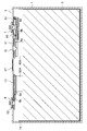
- the square secondary battery 20 includes a battery case 100 including a bottomed square tubular outer body 1 having an opening and a sealing plate 2 for sealing the opening of the square outer body 1. ..
- the square exterior body 1 and the sealing plate 2 are preferably made of metal, and preferably made of aluminum or an aluminum alloy.
- the square exterior body 1 houses an electrode body 3 in which a positive electrode plate and a negative electrode plate are laminated via a separator, together with an electrolyte.
- the electrode body 3 is composed of a first electrode body element and a second electrode body element, and these two electrode body elements have the same structure.
- a positive electrode tab group 40A composed of a plurality of positive electrode tabs (tab portions) 40 and a negative electrode composed of a plurality of negative electrode tabs (tab portions) 50.
- a tab group 50A is provided.
- the positive electrode tab group 40A is electrically connected to the positive electrode terminal 7 via the first positive electrode current collector (positive electrode current collector) 6a and the second positive electrode current collector 6b.
- the negative electrode tab group 50A is electrically connected to the negative electrode terminal 9 via the first negative electrode current collector (negative electrode current collector) 8a and the second negative electrode current collector 8b.
- the first and second positive electrode current collectors 6a and 6b and the first and second negative electrode current collectors 8a and 8b are attached to the inside of the battery of the sealing plate 2, and the positive electrode tab group 40A and the negative electrode tab group 50A are attached. The connection is also made on the inner surface of the battery.
- the second positive electrode current collector 6b, the first positive electrode current collector 6a, and the positive electrode terminal 7 are preferably made of metal, and more preferably made of aluminum or an aluminum alloy.
- An external insulating member 10 made of resin is arranged between the positive electrode terminal 7 and the sealing plate 2.
- a resin internal insulating member 11 is arranged between the second positive electrode current collector 6b and the first positive electrode current collector 6a and the sealing plate 2.
- the second negative electrode current collector 8b, the first negative electrode current collector 8a, and the negative electrode terminal 9 are preferably made of metal, more preferably copper or a copper alloy. Further, it is preferable that the negative electrode terminal 9 has a portion made of aluminum or an aluminum alloy and a portion made of copper or a copper alloy. In this case, it is preferable to connect the portion made of copper or copper alloy to the second negative electrode current collector 8b so that the portion made of aluminum or aluminum alloy protrudes to the outside of the sealing plate 2.
- An external insulating member 12 made of resin is arranged between the negative electrode terminal 9 and the sealing plate 2.
- a resin internal insulating member 13 is arranged between the second negative electrode current collector 8b and the first negative electrode current collector 8a and the sealing plate 2.
- An electrode body holder 14 made of a resin sheet made of resin is arranged between the electrode body 3 and the square exterior body 1.
- the electrode body holder 14 is preferably formed by bending a resin insulating sheet into a bag shape or a box shape.
- the electrode body holder 14 ensures that the electrode body 3 and the square exterior body 1 are electrically insulated from each other.
- the sealing plate 2 is provided with an electrolytic solution injection hole 15, and the electrolytic solution injection hole 15 is sealed by a sealing member (not shown) after the electrolytic solution is injected.
- the sealing plate 2 is provided with a gas discharge valve 17 that breaks when the pressure inside the battery case 100 exceeds a predetermined value and discharges the gas inside the battery case 100 to the outside of the battery case 100.
- the positive electrode active material mixture layer slurry is prepared by kneading, for example, a positive electrode active material, a conductive agent, and a binder.
- the positive electrode active material include lithium composite oxides such as lithium nickel cobalt manganese composite oxides.
- the binder include fluororesins such as polyvinylidene fluoride (PVdF).
- the conductive agent include carbon materials such as carbon black.
- Alumina powder, graphite as a conductive agent, polyvinylidene fluoride (PVdF) as a binder and N-methyl-2-pyrrolidone (NMP) as a dispersion medium are kneaded to prepare a positive electrode protective layer slurry.
- a positive electrode active material mixture layer slurry and a positive electrode protective layer slurry prepared by the above method are applied to both sides of an aluminum foil having a thickness of 15 ⁇ m as a positive electrode core by a die coater. Further, the positive electrode protective layer slurry is applied to at least one end in the width direction of the region to which the positive electrode active material mixture layer slurry is applied.
- the positive electrode core body coated with the positive electrode active material mixture layer slurry and the positive electrode protective layer slurry is dried to remove NMP in the slurry.
- the positive electrode active material mixture layer and the protective layer are formed.
- the positive electrode active material mixture layer is compressed into a positive electrode original plate by passing it between a pair of press rollers.
- the positive electrode original plate is cut to a predetermined size to prepare the positive electrode plate 4 shown in FIG.
- the positive electrode plate 4 is rectangular, and the positive electrode tab 40 projects from the upper side of the rectangle.
- a narrow positive electrode protective layer 4c is formed along the upper side portion of the positive electrode plate 4, and a positive electrode active material mixture layer 4b is formed from below the positive electrode protective layer 4c to the lower side of the positive electrode plate 4.
- the positive electrode tab 40 may be formed from the positive electrode core body, or another member may be connected to the positive electrode plate to form the positive electrode tab.
- the negative electrode active material mixture layer slurry is prepared by kneading, for example, a negative electrode active material, a conductive agent, a binder, and a thickener.
- a negative electrode active material include carbon materials such as graphite.
- the binder include styrene-butadiene rubber (SBR) and the like.
- SBR styrene-butadiene rubber
- the thickener include carboxymethyl cellulose (CMC) and the like.
- the negative electrode active material mixture layer slurry prepared by the above method is applied to both sides of a copper foil having a thickness of 8 ⁇ m as the negative electrode core by a die coater.
- the negative electrode core body coated with the negative electrode active material mixture layer slurry is dried to remove water in the slurry. As a result, the negative electrode active material mixture layer is formed.
- the negative electrode active material mixture layer is compressed into a negative electrode original plate by passing it between a pair of press rollers.
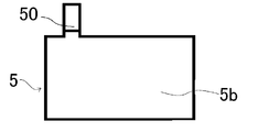
- the negative electrode original plate is cut to a predetermined size to prepare the negative electrode plate 5 shown in FIG.
- the negative electrode plate 4 is rectangular, and the negative electrode tab 50 projects from the upper side of the rectangle.
- the negative electrode active material mixture layer 5b is formed on the entire surface of the negative electrode core body excluding the negative electrode tab 50.
- the negative electrode tab 50 may be formed from the negative electrode core body, or another member may be connected to the negative electrode plate to form the negative electrode tab.
- a plurality of positive electrode plates 4 and negative electrode plates 5 produced by the above method are laminated via a separator to manufacture a laminated electrode body 3.
- the number of each of the positive electrode plate 4 and the negative electrode plate 5 included in the electrode body 3 is not particularly limited, but several tens or more are preferable.
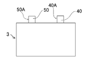
- a positive electrode tab group 40A composed of a plurality of positive electrode tabs 40 and a negative electrode tab group 50A composed of a plurality of negative electrode tabs 50 are provided.
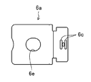
- the positive electrode tab group 40A described above is connected to the first positive electrode current collector 6a shown in FIG. 6 by welding.
- a current collector through hole 6e is formed at a position facing the electrolytic solution injection hole 15 of the sealing plate 2.
- the negative electrode tab group 50A described above is connected to the first negative electrode current collector 8a shown in FIG. 7 by welding.
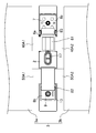
- FIG. 8 shows a state in which the positive electrode tab group 40A and the first positive electrode current collector 6a are connected, and the negative electrode tab group 50A and the first negative electrode current collector 8a are connected.
- the electrode body 3 is composed of a first electrode body element 3a and a second electrode body element 3b.
- the first electrode body element 3a and the second electrode body element 3b are manufactured by the same method as the above-described method for manufacturing the electrode body 3.
- the first positive electrode tab group 40A1 of the first electrode body element 3a and the second positive electrode tab group 40A2 of the second electrode body element 3b are connected to the first positive electrode current collector (positive electrode current collector) 6a, and the first electrode body is connected.
- the first negative electrode tab group 50A1 of the element 3a and the second negative electrode tab group 50A2 of the second electrode body element 3b are connected to the first negative electrode current collector (negative electrode current collector) 8a.
- the first and second positive electrode tab groups 40A1 and 40A2 are welded to the first positive electrode current collector 6a to form welded connection portions 60a and 60b.
- the two welded connection portions 60a and 60b on the positive electrode side are formed so as to be separated from each other in the direction perpendicular to the upper side of the electrode body 3, that is, in the direction perpendicular to the longitudinal direction of the sealing body 2.
- the current collector through hole 6e is located between the two welded connection portions 60a and 60b of the positive electrode.
- the negative electrode tab groups 50A1 and 50A2 are welded to the first negative electrode current collector 8a to form welded connection portions 61a and 61b.
- the two welded connection portions 61a and 61b on the negative electrode side are also formed so as to be separated from each other in the direction perpendicular to the upper side of the electrode body 3, that is, in the direction perpendicular to the longitudinal direction of the sealing body 2.
- a thin-walled portion 6c is formed on the first positive electrode current collector 6a.
- the first positive electrode current collector 6a is connected to the second positive electrode current collector 6b.
- a recess 8d is formed in the first negative electrode current collector 8a, and a thin portion 8c is formed in the recess 8d. In the thin portion 8c, the first negative electrode current collector 8a is connected to the second negative electrode current collector 8b.
- Welding connection between the positive electrode tab group 40A and the first positive electrode current collector 6a and welding connection between the negative electrode tab group 50A and the first negative electrode current collector 8a can be performed by ultrasonic welding, resistance welding, laser welding, or the like. .. In this embodiment, the welding connection is made by ultrasonic welding.
- connection between the first positive electrode current collector 6a and the second positive electrode current collector 6b and the connection between the first negative electrode current collector 8a and the second negative electrode current collector 8b are ultrasonic welding, resistance welding, and the like. It can be performed by laser welding or the like. In this embodiment, they are connected by laser welding.
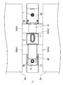
- FIG. 9 is a view showing a surface of the sealing plate 2 to which each component is attached on the inner side of the battery. The attachment of each component to the sealing plate 2 will be described with reference to FIGS. 2 and 9.
- the external insulating member 10 is arranged around the positive electrode terminal insertion hole of the sealing plate 2.
- the internal insulating member 11 and the cup-shaped conductive member 65 are arranged on the inner surface side of the battery around the positive electrode terminal insertion hole of the sealing plate 2. Then, the positive electrode terminal 7 is inserted from the outside of the battery into the through hole of the external insulating member 10, the positive electrode terminal insertion hole of the sealing plate 2, the through hole of the internal insulating member 11, and the terminal connection hole of the conductive member 65, and the positive electrode is inserted. The tip of the terminal 7 is crimped onto the conductive member 65. As a result, the positive electrode terminal 7 and the conductive member 65 are fixed to the sealing plate 2. It is preferable that the crimped portion of the positive electrode terminal 7 and the conductive member 65 are welded and connected.
- the conductive member 65 has an opening on the inner side of the battery.
- a disk-shaped deformed plate 66 is arranged with respect to the opening of the conductive member 65 so as to close the opening, and the peripheral edge of the deformed plate 66 is welded and connected to the conductive member 65. This seals the opening.
- the conductive member 65 and the deformed plate 66 are preferably made of metal, and more preferably made of aluminum or an aluminum alloy. Then, the second positive electrode current collector 6b is arranged inside the battery of the deformed plate 66, and both are welded and connected.
- the external insulating member 12 is arranged on the outer surface side of the battery around the negative electrode terminal insertion hole of the sealing plate 2.
- the internal insulating member 13 and the second negative electrode current collector 8b are arranged on the inner surface side of the battery around the negative electrode terminal insertion hole of the sealing plate 2.
- the negative electrode terminal 9 is inserted from the outside of the battery into the through hole of the external insulating member 12, the negative electrode terminal insertion hole of the sealing plate 2, the through hole of the internal insulating member 13, and the terminal connection hole of the second negative electrode current collector 8b. It is inserted and the tip of the negative electrode terminal 9 is crimped onto the second negative electrode current collector 8b.
- the negative electrode terminal 9 and the second negative electrode current collector 8b are fixed to the sealing plate 2. It is preferable that the crimped portion of the negative electrode terminal 9 and the second negative electrode current collector 8b are welded and connected.
- a liquid injection opening 11a is provided at a portion facing the electrolytic solution injection hole 15 provided in the sealing plate 2. Further, at the edge of the liquid injection opening 11a, a tubular portion 11b protruding into a tubular shape is provided on the inner side of the battery. Further, an opening covering portion 11c is provided which projects from two portions on the edge of the tubular portion 11b toward the inside of the battery and connects the two portions in a bridge shape. Then, the tubular portion 11b and the opening covering portion 11c are inserted into the current collector through hole 6e provided in the first positive electrode current collector 6a.
- FIG. 10 shows the inside of the battery of the sealing plate 2 after the first positive electrode current collector 6a is attached to the second positive electrode current collector 6b and the first negative electrode current collector 8a is attached to the second negative electrode current collector 8b. It is a figure which shows the surface.
- the first positive electrode current collector 6a to which the first and second positive electrode tab groups 40A1 and 40A2 are connected is arranged on the internal insulating member 11 so that a part thereof overlaps with the second positive electrode current collector 6b. .. Then, by irradiating the thin portion 6c with a laser, the first positive electrode current collector 6a and the second positive electrode current collector 6b are welded and connected to form a positive electrode current collector welded connection portion. Further, the first negative electrode current collector 8a to which the first and second negative electrode tab groups 50A1 and 50A2 are connected is placed on the internal insulating member 13 so that a part thereof overlaps with the second negative electrode current collector 8b. Deploy.
- the first negative electrode current collector 8a and the second negative electrode current collector 8b are welded and connected to form a negative electrode current collector welded connection portion.
- the connection portion between the first negative electrode current collector 8a and the second negative electrode current collector 8b will be described in more detail later.
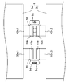
- connection part As shown in FIG. 11, the welded connection portion 60a between the first positive electrode current collector 6a and the first positive electrode tab group 40A1 and the welded connection portion 60b between the first positive electrode current collector 6a and the second positive electrode tab group 40A2 are formed. 1 Covered with a covering member 81. By doing so, the first covering member 81 catches the foreign matter existing in the welding connection portions 60a and 60b, particularly the metal powder generated in the welding process, and prevents the foreign matter from entering the inside of the electrode body 3. Can be. Therefore, the occurrence of internal short circuit due to foreign matter can be greatly suppressed.
- the first covering member 81 is attached to the welded connection portions 60a and 60b, and in the region between the two welded connecting portions 60a and 60b, the first covering member 81 is separated from the region and covers the region. ing.
- the welded connection portion 61a between the first negative electrode current collector 8a and the first negative electrode tab group 50A1 and the welded connection portion 61b between the first negative electrode current collector 8a and the second negative electrode tab group 50A2 are connected to the second covering member 82.
- the second covering member 82 also covers the surface of the first negative electrode current collector 8a sandwiched between the two welded connecting portions 61a and 61b. By doing so, the second covering member 82 catches the foreign matter existing in the welding connection portions 61a and 61b, particularly the metal powder generated in the welding process, and prevents the foreign matter from entering the inside of the electrode body 3. Can be. Therefore, the occurrence of internal short circuit due to foreign matter can be greatly suppressed.
- the second covering member 82 is attached to the covering portion.
- the second covering member 82 also covers the connection portion (negative electrode current collector welded connection portion) between the first negative electrode current collector 8a and the second negative electrode current collector 8b. That is, a part of the second negative electrode current collector 8b is covered with the second covering member 82. Therefore, the second coating member 82 captures the foreign matter (metal powder) generated by the welding of the first negative electrode current collector 8a and the second negative electrode current collector 8b, and the foreign matter does not enter the inside of the electrode body 3. Can be done.
- the third covering member 83 is arranged and bonded so as to cover the connection portion (positive electrode current collector welded connection portion) between the first positive electrode current collector 6a and the second positive electrode current collector 6b.
- the foreign matter existing in the positive electrode current collector welding connection portion particularly the metal powder generated in the welding process between the first positive electrode current collector 6a and the second positive electrode current collector 6b, is the electrode body 3.
- the third covering member 83 can catch foreign matter so as not to get inside the inside.
- the second positive electrode current collector 6b and the third covering member 83 are covered with the cover member 88.
- the first to third covering members 81, 82, 83 use an adhesive sheet in which an adhesive is applied to a plastic film.
- the plastic film is not particularly limited, but a polypropylene film is preferable.
- the first to third covering members 81, 82, 83 are not limited to the adhesive sheet.
- the two positive electrode tab groups 40A1, 40A2 and the two negative electrode tab groups 50A1 so that the upper surface of the first electrode body element 3a and the upper surface of the second electrode body element 3b in FIG. 12 are in direct contact with each other via other members.
- 50A2 is curved.
- the two electrode body elements 3a and 3b are combined into one electrode body 3.
- the combined electrode body 3 is arranged in the electrode body holder 14 made of an insulating sheet formed into a box shape or a bag shape.
- the electrode body 3 wrapped in the electrode body holder 14 is inserted into the square exterior body 1. Then, the sealing plate 2 and the square exterior body 1 are welded, and the opening of the square exterior body 1 is sealed by the sealing plate 2. Then, the electrolytic solution is injected into the square exterior body 1 through the electrolytic solution injection hole 15 provided in the sealing plate 2. After that, the electrolytic solution injection hole 15 is sealed with a sealing member such as a blind rivet. As a result, the square secondary battery 20 is completed.
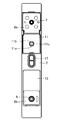
- FIG. 13 shows a state in which only the first negative electrode current collector 8a and the second negative electrode current collector 8b are taken out and overlapped for connection.
- FIG. 14 shows an enlarged cross section of the connecting portion.
- a recess 8d is formed in the first negative electrode current collector 8a, and a surface opposite to the surface on which the recess 8d is formed is overlapped with the second negative electrode current collector 8b.
- Two thin-walled portions 8c are formed in the recess 8d.
- a recess 8f is formed in the first negative electrode current collector 8a by the recess 8d.
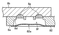
- the thin-walled portion 8c is irradiated with a laser, and as shown in FIG. 15, the first negative electrode current collector 8a and the second negative electrode current collector 8b are connected by through welding. Since laser welding is performed on the thin portion 8c, the through welded portion 8g can be easily formed.
- the second covering member 82 is attached to the first negative electrode current collector 8a and the second negative electrode current collector 8b so as to cover the connection portion between the first negative electrode current collector 8a and the second negative electrode current collector 8b. match. As shown in FIG. 16, the second covering member 82 closes the entire recess 8d (recess 8f), and further penetrates into the recess 8f. That is, the portion 82a of the second covering member 82 that covers the recess 8f has a shape that is recessed along the recess 8f.
- the second covering member 82 has a recess 8c, it is possible to easily align the laser welding using this portion.
- the electrode body may have a structure in which a positive electrode plate, a negative electrode plate, and a separator are laminated and then wound around the electrode body.
- the electrode body element can also have a wound structure.
- the electrode body elements may be one or three or more.
- the positive electrode current collector and the negative electrode current collector are each composed of two parts, but the positive electrode current collector and the negative electrode current collector may each be composed of one component.
- Known materials can be used for the positive electrode plate, the negative electrode plate, the separator, the electrolyte, and the like.
- the covering member may be any material as long as it can capture foreign matter, and is not limited to an adhesive sheet using a plastic film.
- a coating material such as a sealing resin that is cured by heat or light may be used as a coating member, or an adhesive sheet using a metal foil, a non-woven fabric, or the like may be used.
Abstract
電池は、正極板と負極板とがセパレータを介して積層された電極体と、開口を有し、前記電極体を収容する外装体と、前記開口を封口する封口板と、前記封口板に取り付けられた外部端子とを備え、前記正極板及び負極板の少なくとも一方に設けられたタブ部が、前記電極体と前記封口板との間に配置された集電体を介して前記外部端子と電気的に接続されており、前記集電体は、第1集電体及び第2集電体を有しており、前記第1集電体と前記第2集電体とは溶接されているとともに溶接部が被覆部材で覆われている。
Description
本発明は、電池に関するものである。
電気自動車(EV)やハイブリッド電気自動車(HEV、PHEV)の駆動用電源、太陽光発電、風力発電等の出力変動を抑制するための用途や夜間に電力をためて昼間に利用するための系統電力のピークシフト用途等の定置用蓄電池システム等において、アルカリ二次電池や非水電解質二次電池などの電池が使用されている。
上記の電池は、その組み立て中等に異物が混入する場合があり、特に混入した異物が金属異物であると、内部短絡が引き起こされる場合がある。内部短絡のメカニズムとしては以下の通りである。
まず、金属異物が正極材料に付着すると、正極の高い電位によって電解液中に金属イオンとして溶解し、その金属イオンが負極に到達すると金属として析出する。そして、金属が正極に向かって成長するように析出し、金属がセパレータを突き破り正極に接触すると内部短絡が引き起こされる。
電池内へ金属異物等の異物が混入することを防止するために、通常、二次電池の組み立てはクリーンルームで行われる。また、組み立て中に電極体に付着した金属異物は、エアブロー、吸引、磁力吸着、研磨テープによる拭き取り等により除去される。
特許文献1には、袋状の多孔質体に電極体を挿入し、電極体が挿入された多孔質体を密閉容器に挿入して形成される密閉型電池が提案されている。
しかしながら、特許文献1に記載された方法では、電極体と密閉容器の蓋との間に多孔質体を配置する方法やメリットについては具体的に説明されておらず、その具体的方法が不明である。また、袋状の多孔質体を使用するので、その分だけ活物質の量が減少して電池容量が少なくなってしまう。
本発明は、かかる点に鑑みてなされたものであり、その目的とするところは、電池容量を減少させることなく電極体内部への異物の侵入を効果的に抑制することができる電池を提供することにある。
本発明の電池は、正極板と負極板とがセパレータを介して積層された電極体と、開口を有し、前記電極体を収容する外装体と、前記開口を封口する封口板と、前記封口板に取り付けられた外部端子とを備え、前記正極板及び負極板の少なくとも一方に設けられたタブ部が、前記電極体と前記封口板との間に配置された集電体を介して前記外部端子と電気的に接続されており、前記集電体は、第1集電体及び第2集電体を有しており、前記第1集電体と前記第2集電体とは溶接されているとともに溶接部が被覆部材で覆われている構成を有している。
前記第1集電体は凹部を有しており、前記第1集電体と前記第2集電体とが重ねられて前記凹部において溶接が行われており、前記被覆部材は前記凹部を覆っていてもよい。
前記凹部には薄肉部が設けられており、前記薄肉部において前記第1集電体が前記第2集電体に貫通溶接されていてもよい。
前記被覆部材は、前記凹部により形成された窪みの中に入り込んでいてもよい。
なお、本発明の電池は、正極板と負極板とがセパレータを介して積層された電極体と、開口を有し、前記電極体を収容する外装体と、前記開口を封口する封口板と、前記封口板に取り付けられた正極外部端子及び負極外部端子とを備え、前記正極板に設けられた正極タブが、前記電極体と前記封口板との間に配置された正極集電体を介して前記正極外部端子と電気的に接続されており、前記負極板に設けられた負極タブが、前記電極体と前記封口板との間に配置された負極集電体を介して前記負極外部端子と電気的に接続されており、前記正極集電体は、第1正極集電体及び第2正極集電体を有しており、前記第1正極集電体と前記第2正極集電体とは溶接されているとともに溶接部が第1被覆部材で覆われており、前記負極集電体は、第1負極集電体及び第2負極集電体を有しており、前記第1負極集電体と前記第2負極集電体とは溶接されているとともに溶接部が第2被覆部材で覆われている構成を有していてもよい。
前記第1正極集電体は第1凹部を有しており、前記第1正極集電体と前記第2正極集電体とが重ねられて前記第1凹部において溶接が行われており、前記第1被覆部材は前記第1凹部を覆っていてもよい。
前記第1凹部には第1薄肉部が設けられており、前記第1薄肉部において前記第1正極集電体が前記第2正極集電体に貫通溶接されていてもよい。
前記第1被覆部材は、前記第1凹部により形成された窪みの中に入り込んでいてもよい。
前記第1負極集電体は第2凹部を有しており、前記第1負極集電体と前記第2負極集電体とが重ねられて前記第2凹部において溶接が行われており、前記第2被覆部材は前記第2凹部を覆っていてもよい。
前記第2凹部には第2薄肉部が設けられており、前記第2薄肉部において前記第1負極集電体が前記第2負極集電体に貫通溶接されていてもよい。
前記第2被覆部材は、前記第2凹部により形成された窪みの中に入り込んでいてもよい。
本発明の電池は、正極板及び負極板の少なくとも一方に設けられたタブ部が、電極体と封口板との間に配置された集電体を介して外部端子と電気的に接続されており、集電体は、第1集電体及び第2集電体を有しており、第1集電体と第2集電体とは溶接されているとともに溶接部が被覆部材で覆われているため、第1集電体と第2集電体との溶接時に発生する粉塵が電極体の内部に入ってしまうことをより効果的に抑制できる。
以下、本発明の実施形態を図面に基づいて詳細に説明する。以下の好ましい実施形態の説明は、本質的に例示に過ぎず、本発明、その適用物或いはその用途を制限することを意図するものではない。以下の図面においては、説明の簡潔化のため、実質的に同一の機能を有する構成要素を同一の参照符号で示す。
(実施形態1)
実施形態1に係る二次電池としての角形二次電池20の構成を以下に説明する。なお、本発明は、以下の実施形態に限定されない。
実施形態1に係る二次電池としての角形二次電池20の構成を以下に説明する。なお、本発明は、以下の実施形態に限定されない。
図1及び図2に示すように角形二次電池20は、開口を有する有底角筒状の角形外装体1と、角形外装体1の開口を封口する封口板2からなる電池ケース100を備える。角形外装体1及び封口板2は、それぞれ金属製であることが好ましく、アルミニウム又はアルミニウム合金製であることが好ましい。角形外装体1は、正極板と負極板とがセパレータを介して積層された電極体3を、電解質と共に収容している。後述するように、本実施形態では電極体3は第1電極体要素と第2電極体要素からなっており、これら2つの電極体要素は同じ構造を有している。
図5に示すように、電極体3の封口板2側の端部には、複数の正極タブ(タブ部)40からなる正極タブ群40Aと、複数の負極タブ(タブ部)50からなる負極タブ群50Aが設けられている。正極タブ群40Aは第1正極集電体(正極集電体)6a及び第2正極集電体6bを介して正極端子7に電気的に接続されている。負極タブ群50Aは第1負極集電体(負極集電体)8a及び第2負極集電体8bを介して負極端子9に電気的に接続されている。第1、第2正極集電体6a,6b及び第1、第2負極集電体8a,8bは、封口板2の電池内部側に取り付けられており、正極タブ群40A及び負極タブ群50Aとの接続も電池内部側の面においてなされている。
第2正極集電体6b、第1正極集電体6a及び正極端子7は金属製であることが好ましく、アルミニウム又はアルミニウム合金製であることがより好ましい。正極端子7と封口板2の間には樹脂製の外部側絶縁部材10が配置されている。第2正極集電体6b及び第1正極集電体6aと封口板2の間には樹脂製の内部側絶縁部材11が配置されている。
第2負極集電体8b、第1負極集電体8a及び負極端子9は金属製であることが好ましく、銅又は銅合金製であることがより好ましい。また、負極端子9は、アルミニウム又はアルミニウム合金からなる部分と、銅又は銅合金からなる部分を有するようにすることが好ましい。この場合、銅又は銅合金からなる部分を第2負極集電体8bに接続し、アルミニウム又はアルミニウム合金からなる部分を封口板2よりも外部側に突出するようにすることが好ましい。負極端子9と封口板2の間には樹脂製の外部側絶縁部材12が配置されている。第2負極集電体8b及び第1負極集電体8aと封口板2の間には樹脂製の内部側絶縁部材13が配置されている。
電極体3と角形外装体1の間には樹脂製の樹脂シートからなる電極体ホルダー14が配置されている。電極体ホルダー14は、樹脂製の絶縁シートを袋状又は箱状に折り曲げ成形されたものであることが好ましい。この電極体ホルダー14により、電極体3と角形外装体1との間が確実に電気的に絶縁状態として保持されている。
封口板2には電解液注液孔15が設けられており、電解液注液孔15は電解液の注液後に封止部材(不図示)によって封止される。封口板2には、電池ケース100内の圧力が所定値以上となったときに破断して、電池ケース100内のガスを電池ケース100外に排出するガス排出弁17が設けられている。
次に角形二次電池20の製造方法及び各構成の詳細を説明する。
[正極板]
まず、正極板の製造方法を説明する。
まず、正極板の製造方法を説明する。
[正極活物質合剤層スラリーの作製]
正極活物質合剤層スラリーは、例えば正極活物質と、導電剤と、結着剤とを混練して作製する。正極活物質としては、例えばリチウムニッケルコバルトマンガン複合酸化物等のリチウム複合酸化物等を挙げることができる。また、結着剤としては、例えば、ポリフッ化ビニリデン(PVdF)等のフッ素樹脂等を挙げることができる。導電剤としては、カーボンブラック等の炭素材料等を挙げることができる。
正極活物質合剤層スラリーは、例えば正極活物質と、導電剤と、結着剤とを混練して作製する。正極活物質としては、例えばリチウムニッケルコバルトマンガン複合酸化物等のリチウム複合酸化物等を挙げることができる。また、結着剤としては、例えば、ポリフッ化ビニリデン(PVdF)等のフッ素樹脂等を挙げることができる。導電剤としては、カーボンブラック等の炭素材料等を挙げることができる。
[正極保護層スラリーの作製]
アルミナ粉末、導電剤としての黒鉛、結着剤としてのポリフッ化ビニリデン(PVdF)と分散媒としてのN-メチル-2-ピロリドン(NMP)などを混練し、正極保護層スラリーを作製する。
アルミナ粉末、導電剤としての黒鉛、結着剤としてのポリフッ化ビニリデン(PVdF)と分散媒としてのN-メチル-2-ピロリドン(NMP)などを混練し、正極保護層スラリーを作製する。
[正極活物質合剤層及び正極保護層の形成]
正極芯体としての厚さ15μmのアルミニウム箔の両面に、上述の方法で作製した正極活物質合剤層スラリー及び正極保護層スラリーをダイコータにより塗布する。また、正極活物質合剤層スラリーが塗布される領域の幅方向の少なくともどちらか一方の端部に正極保護層スラリーが塗布されるようにする。
正極芯体としての厚さ15μmのアルミニウム箔の両面に、上述の方法で作製した正極活物質合剤層スラリー及び正極保護層スラリーをダイコータにより塗布する。また、正極活物質合剤層スラリーが塗布される領域の幅方向の少なくともどちらか一方の端部に正極保護層スラリーが塗布されるようにする。
正極活物質合剤層スラリー及び正極保護層スラリーが塗布された正極芯体を乾燥させて、スラリー中のNMPを除去する。これにより正極活物質合剤層及び保護層が形成される。その後、一対のプレスローラの間を通過させることにより、正極活物質合剤層を圧縮して正極原板とする。この正極原板を所定のサイズにカットして図3に示す正極板4を作成する。正極板4は矩形であって、矩形の上辺から正極タブ40が突き出している。正極板4の上辺部分に沿って幅狭の正極保護層4cが形成されており、正極保護層4cの下から正極板4の下辺まで正極活物質合剤層4bが形成されている。なお、上述のように正極タブ40は正極芯体から形成されてもよいし、別の部材を正極板に接続して正極タブとしてもよい。
[負極板]
次に、負極板の製造方法を説明する。
次に、負極板の製造方法を説明する。
[負極活物質合剤層スラリーの作製]
負極活物質合剤層スラリーは、例えば負極活物質と、導電剤と、結着剤と、増粘剤とを混練して作製する。負極活物質としては、例えば、黒鉛等の炭素材料等を挙げることができる。結着剤としては、例えば、スチレンブタジエンゴム(SBR)等を挙げることができる。増粘剤としては、例えば、カルボキシメチルセルロース(CMC)等を挙げることができる。
負極活物質合剤層スラリーは、例えば負極活物質と、導電剤と、結着剤と、増粘剤とを混練して作製する。負極活物質としては、例えば、黒鉛等の炭素材料等を挙げることができる。結着剤としては、例えば、スチレンブタジエンゴム(SBR)等を挙げることができる。増粘剤としては、例えば、カルボキシメチルセルロース(CMC)等を挙げることができる。
[負極活物質合剤層の形成]
負極芯体としての厚さ8μmの銅箔の両面に、上述の方法で作製した負極活物質合剤層スラリーをダイコータにより塗布する。
負極芯体としての厚さ8μmの銅箔の両面に、上述の方法で作製した負極活物質合剤層スラリーをダイコータにより塗布する。
負極活物質合剤層スラリーが塗布された負極芯体を乾燥させ、スラリー中の水を除去する。これにより負極活物質合剤層が形成される。その後、一対のプレスローラの間を通過させることにより、負極活物質合剤層を圧縮して負極原板とする。この負極原板を所定のサイズにカットして図4に示す負極板5を作成する。負極板4は矩形であって、矩形の上辺から負極タブ50が突き出している。負極タブ50を除いた負極芯体の全面に負極活物質合剤層5bが形成されている。なお、上述のように負極タブ50は負極芯体から形成されてもよいし、別の部材を負極板に接続して負極タブとしてもよい。
[電極体の作製]
上述の方法で作製した複数の正極板4及び負極板5を、セパレータを介して積層し、積層型の電極体3を製造する。電極体3に含まれる正極板4及び負極板5のそれぞれの数は特に限定されないが、数十枚以上が好ましい。図5に示すように電極体3の一つの端部には、複数の正極タブ40からなる正極タブ群40Aと、複数の負極タブ50からなる負極タブ群50Aが設けられる。
上述の方法で作製した複数の正極板4及び負極板5を、セパレータを介して積層し、積層型の電極体3を製造する。電極体3に含まれる正極板4及び負極板5のそれぞれの数は特に限定されないが、数十枚以上が好ましい。図5に示すように電極体3の一つの端部には、複数の正極タブ40からなる正極タブ群40Aと、複数の負極タブ50からなる負極タブ群50Aが設けられる。
[集電体とタブの接続]
上述の正極タブ群40Aは、図6に示す第1正極集電体6aに溶接によって接続される。第1正極集電体6aには、封口板2の電解液注液孔15と対向する位置に集電体貫通穴6eが形成されている。また、上述の負極タブ群50Aは、図7に示す第1負極集電体8aに溶接によって接続される。図8に正極タブ群40Aと第1正極集電体6aとを接続し、負極タブ群50Aと第1負極集電体8aとを接続した状態を示す。
上述の正極タブ群40Aは、図6に示す第1正極集電体6aに溶接によって接続される。第1正極集電体6aには、封口板2の電解液注液孔15と対向する位置に集電体貫通穴6eが形成されている。また、上述の負極タブ群50Aは、図7に示す第1負極集電体8aに溶接によって接続される。図8に正極タブ群40Aと第1正極集電体6aとを接続し、負極タブ群50Aと第1負極集電体8aとを接続した状態を示す。
本実施形態では、図8に示すように、電極体3は第1電極体要素3aと第2電極体要素3bとからなっている。なお、第1電極体要素3aと第2電極体要素3bは上述の電極体3の作製方法と同じ方法で作製される。
第1電極体要素3aの第1正極タブ群40A1及び第2電極体要素3bの第2正極タブ群40A2を第1正極集電体(正極集電体)6aに接続すると共に、第1電極体要素3aの第1負極タブ群50A1及び第2電極体要素3bの第2負極タブ群50A2を第1負極集電体(負極集電体)8aに接続する。第1及び第2正極タブ群40A1,40A2は第1正極集電体6aに溶接接続され溶接接続部60a,60bが形成される。正極側の2つの溶接接続部60a,60bは電極体3の上辺に垂直な方向、即ち、封口体2の長手方向に垂直な方向において互いに離間して形成されている。なお、集電体貫通孔6eは正極の2つの溶接接続部60a,60bの間に位置している。
負極タブ群50A1,50A2は第1負極集電体8aに溶接接続され溶接接続部61a,61bが形成される。負極側の2つの溶接接続部61a,61bも電極体3の上辺に垂直な方向、即ち、封口体2の長手方向に垂直な方向において互いに離間して形成されている。
第1正極集電体6aには、薄肉部6cが形成されている。この薄肉部6cにおいて、第1正極集電体6aは第2正極集電体6bに接続される。
第1負極集電体8aには、凹部8dが形成されており、凹部8dに薄肉部8cが形成されている。この薄肉部8cにおいて、第1負極集電体8aは第2負極集電体8bに接続される。
正極タブ群40Aと第1正極集電体6aとの溶接接続及び負極タブ群50Aと第1負極集電体8aとの溶接接続は、超音波溶接、抵抗溶接、レーザー溶接等により行うことができる。本実施形態では超音波溶接によって溶接接続がなされている。
また、第1正極集電体6aと第2正極集電体6bとの接続、及び、第1負極集電体8aと第2負極集電体8bとの接続は、超音波溶接、抵抗溶接、レーザー溶接等により行うことができる。本実施形態では、レーザー溶接によって接続がされている。
[封口板への各部品取り付け]
図9は、各部品を取り付けた封口板2の電池内部側の面を示す図である。図2、図9を用いて、封口板2への各部品取り付けについて説明を行う。
図9は、各部品を取り付けた封口板2の電池内部側の面を示す図である。図2、図9を用いて、封口板2への各部品取り付けについて説明を行う。
封口板2の正極端子挿入孔の周囲に外部側絶縁部材10を配置する。封口板2の正極端子挿入孔の周囲の電池内面側に内部側絶縁部材11及びカップ状の導電部材65を配置する。そして、正極端子7を電池外部側から、外部側絶縁部材10の貫通孔、封口板2の正極端子挿入孔、内部側絶縁部材11の貫通孔及び導電部材65の端子接続孔に挿入し、正極端子7の先端を導電部材65上にカシメる。これにより、正極端子7及び導電部材65が封口板2に固定される。なお、正極端子7においてカシメられた部分と導電部材65を溶接接続することが好ましい。
導電部材65は電池内部側に開口部を有している。この導電部材65の開口部に対して、円盤状の変形板66がその開口部を塞ぐように配置されて、変形板66の周縁が導電部材65に溶接接続される。これにより、開口部が密封される。なお、導電部材65及び変形板66はそれぞれ金属製であることが好ましく、アルミニウム又はアルミニウム合金製であることがより好ましい。それから第2正極集電体6bを変形板66の電池内部側に配置して、両者を溶接接続する。
次に、封口板2の負極端子挿入孔の周囲の電池外面側に外部側絶縁部材12を配置する。封口板2の負極端子挿入孔の周囲の電池内面側に内部側絶縁部材13及び第2負極集電体8bを配置する。そして、負極端子9を電池外部側から、外部側絶縁部材12の貫通孔、封口板2の負極端子挿入孔、内部側絶縁部材13の貫通孔及び第2負極集電体8bの端子接続孔に挿入し、負極端子9の先端を第2負極集電体8b上にカシメる。これにより、負極端子9及び第2負極集電体8bが封口板2に固定される。なお、負極端子9においてカシメられた部分と第2負極集電体8bを溶接接続することが好ましい。
正極側の内部側絶縁部材11において、封口板2に設けられた電解液注液孔15と対向する部分には、注液開口11aが設けられている。また、注液開口11aの縁部には電池内部側に筒状に突き出した筒状部11bが設けられている。さらに、筒状部11bの縁の2箇所から電池内部側に突き出して当該2箇所をブリッジ状に連結している開口覆い部11cが設けられている。そして、第1正極集電体6aに設けられた集電体貫通穴6eに筒状部11b、開口覆い部11cが挿入される。
[第1集電体と第2集電体の接続]
図10は、第2正極集電体6bに第1正極集電体6aを取り付け、第2負極集電体8bに第1負極集電体8aを取り付けた後の封口板2の電池内部側の面を示す図である。
図10は、第2正極集電体6bに第1正極集電体6aを取り付け、第2負極集電体8bに第1負極集電体8aを取り付けた後の封口板2の電池内部側の面を示す図である。
第1及び第2正極タブ群40A1,40A2が接続された第1正極集電体6aを、その一部が第2正極集電体6bと重なるようにして、内部側絶縁部材11上に配置する。そして、薄肉部6cにレーザー照射することにより、第1正極集電体6aと第2正極集電体6bを溶接接続し、正極集電体溶接接続部が形成される。また、第1及び第2負極タブ群50A1,50A2が接続された第1負極集電体8aを、その一部が第2負極集電体8bと重なるようにして、内部側絶縁部材13上に配置する。そして、薄肉部8cにレーザー照射することにより、第1負極集電体8aと第2負極集電体8bを溶接接続し、負極集電体溶接接続部が形成される。なお、第1負極集電体8aと第2負極集電体8bとの接続部分に関しては、より詳しく後述する。
[接続部の被覆]
図11に示すように、第1正極集電体6aと第1正極タブ群40A1との溶接接続部60a及び第1正極集電体6aと第2正極タブ群40A2との溶接接続部60bを第1被覆部材81によって覆う。このようにすることにより、第1被覆部材81が溶接接続部60a,60bに存在している異物、特に溶接工程において発生した金属粉を捕捉して、異物が電極体3の内部に入り込まないようにすることができる。従って、異物による内部短絡の発生を大きく抑制することができる。第1被覆部材81は溶接接続部60a,60bに貼り合わされており、2つの溶接接続部60a,60bの間の領域においては、第1被覆部材81はその領域から離間して且つその領域を覆っている。
図11に示すように、第1正極集電体6aと第1正極タブ群40A1との溶接接続部60a及び第1正極集電体6aと第2正極タブ群40A2との溶接接続部60bを第1被覆部材81によって覆う。このようにすることにより、第1被覆部材81が溶接接続部60a,60bに存在している異物、特に溶接工程において発生した金属粉を捕捉して、異物が電極体3の内部に入り込まないようにすることができる。従って、異物による内部短絡の発生を大きく抑制することができる。第1被覆部材81は溶接接続部60a,60bに貼り合わされており、2つの溶接接続部60a,60bの間の領域においては、第1被覆部材81はその領域から離間して且つその領域を覆っている。
次に、第1負極集電体8aと第1負極タブ群50A1との溶接接続部61a及び第1負極集電体8aと第2負極タブ群50A2との溶接接続部61bを第2被覆部材82によって覆う。第2被覆部材82は、2つの溶接接続部61a,61bに挟まれた第1負極集電体8aの表面も覆っている。このようにすることにより、第2被覆部材82が溶接接続部61a,61bに存在している異物、特に溶接工程において発生した金属粉を捕捉して、異物が電極体3の内部に入り込まないようにすることができる。従って、異物による内部短絡の発生を大きく抑制することができる。なお、第2被覆部材82は、覆っている部分に貼り合わせられるている。
さらに、第2被覆部材82は第1負極集電体8aと第2負極集電体8bとの接続部分(負極集電体溶接接続部)も覆っている。即ち、第2負極集電体8bの一部が第2被覆部材82によって覆われている。このため、第1負極集電体8aと第2負極集電体8bとの溶接によって生じた異物(金属粉)を第2被覆部材82が捕捉し、この異物が電極体3の内部に入り込まないようにすることができる。
それから、第1正極集電体6aと第2正極集電体6bとの接続部分(正極集電体溶接接続部)を覆うように第3被覆部材83を配置し、貼り合わせる。このようにすることにより、正極集電体溶接接続部に存在している異物、特に第1正極集電体6aと第2正極集電体6bとの溶接工程において発生した金属粉が電極体3の内部に入り込まないように、第3被覆部材83が異物を捕捉することができる。それから、図12に示すように第2正極集電体6bと第3被覆部材83とをカバー部材88によって覆う。
本実施形態では第1から第3被覆部材81,82,83は、プラスチックフィルムに粘着剤を塗布した粘着シートを用いている。プラスチックフィルムは特に限定されないが、ポリプロピレンフィルムが好ましい。なお、第1から第3被覆部材81,82,83は粘着シートに限定されない。
[二次電池の作製]
次に図12における第1電極体要素3aの上面と第2電極体要素3bの上面とが直接ないし他の部材を介して接するように二つの正極タブ群40A1,40A2及び二つの負極タブ群50A1,50A2を湾曲させる。これにより、二つの電極体要素3a,3bを纏めて1つの電極体3とする。そして、まとめた電極体3を、箱状ないし袋状に成形した絶縁シートからなる電極体ホルダー14内に配置する。
次に図12における第1電極体要素3aの上面と第2電極体要素3bの上面とが直接ないし他の部材を介して接するように二つの正極タブ群40A1,40A2及び二つの負極タブ群50A1,50A2を湾曲させる。これにより、二つの電極体要素3a,3bを纏めて1つの電極体3とする。そして、まとめた電極体3を、箱状ないし袋状に成形した絶縁シートからなる電極体ホルダー14内に配置する。
電極体ホルダー14で包まれた電極体3を角形外装体1に挿入する。そして、封口板2と角形外装体1を溶接し、角形外装体1の開口を封口板2により封口する。それから、封口板2に設けられた電解液注液孔15を通じて角形外装体1内に電解液を注液する。その後、電解液注液孔15をブラインドリベット等の封止部材により封止する。これにより角形二次電池20が完成する。
<第1負極集電体と第2負極集電体との接続部分について>
第1負極集電体8aと第2負極集電体8bとの接続部分についてさらに説明を行う。図13は第1負極集電体8a及び第2負極集電体8bのみを取り出して、接続のために重ね合わせた状態を示している。図14は、接続する部分を拡大した断面を示している。第1負極集電体8aには凹部8dが形成されており、その凹部8dが形成された面とは反対側の面が第2負極集電体8bと重ね合わされている。凹部8dには薄肉部8cが2箇所形成されている。第1負極集電体8aには凹部8dにより窪み8fが形成されている。
第1負極集電体8aと第2負極集電体8bとの接続部分についてさらに説明を行う。図13は第1負極集電体8a及び第2負極集電体8bのみを取り出して、接続のために重ね合わせた状態を示している。図14は、接続する部分を拡大した断面を示している。第1負極集電体8aには凹部8dが形成されており、その凹部8dが形成された面とは反対側の面が第2負極集電体8bと重ね合わされている。凹部8dには薄肉部8cが2箇所形成されている。第1負極集電体8aには凹部8dにより窪み8fが形成されている。
上記の状態から、薄肉部8cの部分にレーザーを照射して、図15に示すように第1負極集電体8aと第2負極集電体8bとを貫通溶接によって接続する。薄肉部8cにおいてレーザー溶接するため、貫通溶接部8gを容易に形成することができる。
次に第2被覆部材82を、第1負極集電体8aと第2負極集電体8bとの接続部分も覆うように、第1負極集電体8a及び第2負極集電体8bに貼り合わせる。図16に示すように第2被覆部材82は、凹部8d(窪み8f)全体を塞いでおり、さらに窪み8f内に入り込んでいる。すなわち、第2被覆部材82の窪み8fを覆った部分82aは窪み8fに沿って凹んだ形状を有している。
第2被覆部材82が凹部8cが存在しているために、この部分を用いてレーザー溶接の位置合わせを容易に行うことができる。
(その他の実施形態)
上述の実施形態は本願発明の例示であって、本願発明はこれらの例に限定されず、これらの例に周知技術や慣用技術、公知技術を組み合わせたり、一部置き換えたりしてもよい。また当業者であれば容易に思いつく改変発明も本願発明に含まれる。
上述の実施形態は本願発明の例示であって、本願発明はこれらの例に限定されず、これらの例に周知技術や慣用技術、公知技術を組み合わせたり、一部置き換えたりしてもよい。また当業者であれば容易に思いつく改変発明も本願発明に含まれる。
電極体は、正極板、負極板及びセパレータを積層したあとで、これを巻回させた構造であってもよい。電極体要素も巻回構造とすることができる。
上述の実施形態においては、外装体内に二つの電極体要素を配置する例を示したが、電極体要素は一つであっても良いし、三つ以上であってもよい。
上述の実施形態においては、正極集電体及び負極集電体がそれぞれ二つの部品からなる例を示したが、正極集電体及び負極集電体はそれぞれ一つの部品から構成されてもよい。
正極板、負極板、セパレータ、及び電解質等に関しては、公知の材料を用いることができる。
被覆部材は異物を捕捉できるものであればどのようなものでもよく、プラスチックフィルムを用いた粘着シートに限定されない。例えば、熱や光等で硬化する封止樹脂等の塗布材料を被覆部材として用いてもよいし、金属箔や不織布などを用いた粘着シートでもよい。
1 角形外装体(外装体)
2 封口板
3 電極体
3a 第1電極体要素
3b 第2電極体要素
4 正極板
5 負極板
6a 第1正極集電体
6b 第2正極集電体
6e 集電体貫通穴(注液孔)
7 正極端子(正極外部端子)
8a 第1負極集電体
8b 第2負極集電体
8c 薄肉部
8d 凹部
8f 窪み
8g 貫通溶接部
9 負極端子(負極外部端子)
11b 筒状部
11c 開口覆い部
15 電解液注液孔
20 角形二次電池(電池)
40 正極タブ(タブ部)
40A 正極タブ群
40A1 第1正極タブ群
40A2 第2正極タブ群
50 負極タブ(タブ部)
50A 負極タブ群
50A1 第1負極タブ群
50A2 第2負極タブ群
60a,60b 溶接接続部(第1溶接部)
61a,61b 溶接接続部(第2溶接部)
81 第1被覆部材
82 第2被覆部材
Claims (4)
- 正極板と負極板とがセパレータを介して積層された電極体と、
開口を有し、前記電極体を収容する外装体と、
前記開口を封口する封口板と、
前記封口板に取り付けられた外部端子と
を備え、
前記正極板及び負極板の少なくとも一方に設けられたタブ部が、前記電極体と前記封口板との間に配置された集電体を介して前記外部端子と電気的に接続されており、
前記集電体は、第1集電体及び第2集電体を有しており、
前記第1集電体と前記第2集電体とは溶接されているとともに溶接部が被覆部材で覆われている、電池。 - 前記第1集電体は凹部を有しており、
前記第1集電体と前記第2集電体とが重ねられて前記凹部において溶接が行われており、
前記被覆部材は前記凹部を覆っている、請求項1に記載の電池。 - 前記凹部には薄肉部が設けられており、
前記薄肉部において前記第1集電体が前記第2集電体に貫通溶接されている、請求項2に記載の電池。 - 前記被覆部材は、前記凹部により形成された窪みの中に入り込んでいる、請求項2又は3に記載の電池。
Priority Applications (4)
| Application Number | Priority Date | Filing Date | Title |
|---|---|---|---|
| CN202080054476.7A CN114207885A (zh) | 2019-08-07 | 2020-06-23 | 电池 |
| US17/632,403 US20220285765A1 (en) | 2019-08-07 | 2020-06-23 | Battery |
| EP20850241.9A EP4012796A4 (en) | 2019-08-07 | 2020-06-23 | DRUMS |
| JP2021537614A JPWO2021024631A1 (ja) | 2019-08-07 | 2020-06-23 |
Applications Claiming Priority (2)
| Application Number | Priority Date | Filing Date | Title |
|---|---|---|---|
| JP2019145762 | 2019-08-07 | ||
| JP2019-145762 | 2019-08-07 |
Publications (1)
| Publication Number | Publication Date |
|---|---|
| WO2021024631A1 true WO2021024631A1 (ja) | 2021-02-11 |
Family
ID=74502913
Family Applications (1)
| Application Number | Title | Priority Date | Filing Date |
|---|---|---|---|
| PCT/JP2020/024537 WO2021024631A1 (ja) | 2019-08-07 | 2020-06-23 | 電池 |
Country Status (5)
| Country | Link |
|---|---|
| US (1) | US20220285765A1 (ja) |
| EP (1) | EP4012796A4 (ja) |
| JP (1) | JPWO2021024631A1 (ja) |
| CN (1) | CN114207885A (ja) |
| WO (1) | WO2021024631A1 (ja) |
Citations (6)
| Publication number | Priority date | Publication date | Assignee | Title |
|---|---|---|---|---|
| JP2009087812A (ja) | 2007-10-01 | 2009-04-23 | Toyota Motor Corp | 密閉型電池 |
| JP2011159582A (ja) * | 2010-02-03 | 2011-08-18 | Toyota Motor Corp | 電池及びその製造方法 |
| JP2016091670A (ja) * | 2014-10-31 | 2016-05-23 | 日立オートモティブシステムズ株式会社 | 円筒形二次電池 |
| WO2018021372A1 (ja) * | 2016-07-29 | 2018-02-01 | 三洋電機株式会社 | 二次電池 |
| JP2019012589A (ja) * | 2017-06-29 | 2019-01-24 | 三洋電機株式会社 | 角形二次電池及びその製造方法 |
| JP2019125493A (ja) * | 2018-01-17 | 2019-07-25 | 三洋電機株式会社 | 二次電池 |
Family Cites Families (5)
| Publication number | Priority date | Publication date | Assignee | Title |
|---|---|---|---|---|
| JP6935798B2 (ja) * | 2016-07-29 | 2021-09-15 | 三洋電機株式会社 | 二次電池の製造方法 |
| JP6972703B2 (ja) * | 2017-06-26 | 2021-11-24 | 三洋電機株式会社 | 角形二次電池 |
| JP7167427B2 (ja) * | 2017-11-09 | 2022-11-09 | 三洋電機株式会社 | 二次電池 |
| JP6962168B2 (ja) * | 2017-12-12 | 2021-11-05 | 三洋電機株式会社 | 角形二次電池及びその製造方法 |
| JP6805288B2 (ja) * | 2019-04-22 | 2020-12-23 | 三洋電機株式会社 | 角形二次電池及びそれを用いた組電池 |
-
2020
- 2020-06-23 WO PCT/JP2020/024537 patent/WO2021024631A1/ja unknown
- 2020-06-23 EP EP20850241.9A patent/EP4012796A4/en active Pending
- 2020-06-23 US US17/632,403 patent/US20220285765A1/en active Pending
- 2020-06-23 CN CN202080054476.7A patent/CN114207885A/zh active Pending
- 2020-06-23 JP JP2021537614A patent/JPWO2021024631A1/ja active Pending
Patent Citations (6)
| Publication number | Priority date | Publication date | Assignee | Title |
|---|---|---|---|---|
| JP2009087812A (ja) | 2007-10-01 | 2009-04-23 | Toyota Motor Corp | 密閉型電池 |
| JP2011159582A (ja) * | 2010-02-03 | 2011-08-18 | Toyota Motor Corp | 電池及びその製造方法 |
| JP2016091670A (ja) * | 2014-10-31 | 2016-05-23 | 日立オートモティブシステムズ株式会社 | 円筒形二次電池 |
| WO2018021372A1 (ja) * | 2016-07-29 | 2018-02-01 | 三洋電機株式会社 | 二次電池 |
| JP2019012589A (ja) * | 2017-06-29 | 2019-01-24 | 三洋電機株式会社 | 角形二次電池及びその製造方法 |
| JP2019125493A (ja) * | 2018-01-17 | 2019-07-25 | 三洋電機株式会社 | 二次電池 |
Also Published As
| Publication number | Publication date |
|---|---|
| EP4012796A4 (en) | 2023-01-04 |
| JPWO2021024631A1 (ja) | 2021-02-11 |
| EP4012796A1 (en) | 2022-06-15 |
| US20220285765A1 (en) | 2022-09-08 |
| CN114207885A (zh) | 2022-03-18 |
Similar Documents
| Publication | Publication Date | Title |
|---|---|---|
| JP7402175B2 (ja) | 電池及びその製造方法 | |
| CN110326124B (zh) | 方形二次电池 | |
| JPWO2014097586A1 (ja) | 円筒形二次電池及びその製造方法 | |
| US20220352606A1 (en) | Secondary battery and method for manufacturing same | |
| US11824166B2 (en) | Secondary battery | |
| JP7330211B2 (ja) | 角形二次電池 | |
| JP6935798B2 (ja) | 二次電池の製造方法 | |
| WO2021024629A1 (ja) | 電池 | |
| WO2021024630A1 (ja) | 電池 | |
| CN108232310B (zh) | 方形二次电池及其制造方法 | |
| JP2001102031A (ja) | 電気エネルギー蓄積デバイス及びその製造方法 | |
| WO2021024631A1 (ja) | 電池 | |
| CN111971820A (zh) | 非水电解质二次电池用电极板及非水电解质二次电池 | |
| JP2020030899A (ja) | 二次電池 | |
| WO2020129999A1 (ja) | 二次電池用の電極板及びそれを用いた二次電池 | |
| US20220059827A1 (en) | Secondary battery electrode plate and secondary battery using same | |
| CN114175391B (zh) | 电池 | |
| JP2020170636A (ja) | 積層型電池 | |
| JP6889222B2 (ja) | 積層型電池および積層型電池の製造方法 | |
| WO2021176961A1 (ja) | 二次電池 | |
| US20220069283A1 (en) | Electrode plate for secondary batteries, and secondary battery using same | |
| JP2020140833A (ja) | 積層型電池および積層型電池の製造方法 |
Legal Events
| Date | Code | Title | Description |
|---|---|---|---|
| ENP | Entry into the national phase |
Ref document number: 2021537614 Country of ref document: JP Kind code of ref document: A |
|
| NENP | Non-entry into the national phase |
Ref country code: DE |
|
| ENP | Entry into the national phase |
Ref document number: 2020850241 Country of ref document: EP Effective date: 20220307 |