WO2021020201A1 - 聴診器 - Google Patents
聴診器 Download PDFInfo
- Publication number
- WO2021020201A1 WO2021020201A1 PCT/JP2020/028079 JP2020028079W WO2021020201A1 WO 2021020201 A1 WO2021020201 A1 WO 2021020201A1 JP 2020028079 W JP2020028079 W JP 2020028079W WO 2021020201 A1 WO2021020201 A1 WO 2021020201A1
- Authority
- WO
- WIPO (PCT)
- Prior art keywords
- contact surface
- stethoscope
- living body
- electrode
- rubber
- Prior art date
Links
Images


Classifications
-
- A—HUMAN NECESSITIES
- A61—MEDICAL OR VETERINARY SCIENCE; HYGIENE
- A61B—DIAGNOSIS; SURGERY; IDENTIFICATION
- A61B7/00—Instruments for auscultation
- A61B7/02—Stethoscopes
- A61B7/04—Electric stethoscopes
-
- A—HUMAN NECESSITIES
- A61—MEDICAL OR VETERINARY SCIENCE; HYGIENE
- A61B—DIAGNOSIS; SURGERY; IDENTIFICATION
- A61B5/00—Measuring for diagnostic purposes; Identification of persons
- A61B5/24—Detecting, measuring or recording bioelectric or biomagnetic signals of the body or parts thereof
- A61B5/25—Bioelectric electrodes therefor
- A61B5/279—Bioelectric electrodes therefor specially adapted for particular uses
- A61B5/28—Bioelectric electrodes therefor specially adapted for particular uses for electrocardiography [ECG]
- A61B5/282—Holders for multiple electrodes
-
- A—HUMAN NECESSITIES
- A61—MEDICAL OR VETERINARY SCIENCE; HYGIENE
- A61B—DIAGNOSIS; SURGERY; IDENTIFICATION
- A61B5/00—Measuring for diagnostic purposes; Identification of persons
- A61B5/24—Detecting, measuring or recording bioelectric or biomagnetic signals of the body or parts thereof
- A61B5/316—Modalities, i.e. specific diagnostic methods
- A61B5/318—Heart-related electrical modalities, e.g. electrocardiography [ECG]
- A61B5/33—Heart-related electrical modalities, e.g. electrocardiography [ECG] specially adapted for cooperation with other devices
-
- A—HUMAN NECESSITIES
- A61—MEDICAL OR VETERINARY SCIENCE; HYGIENE
- A61B—DIAGNOSIS; SURGERY; IDENTIFICATION
- A61B5/00—Measuring for diagnostic purposes; Identification of persons
- A61B5/24—Detecting, measuring or recording bioelectric or biomagnetic signals of the body or parts thereof
- A61B5/316—Modalities, i.e. specific diagnostic methods
- A61B5/318—Heart-related electrical modalities, e.g. electrocardiography [ECG]
- A61B5/332—Portable devices specially adapted therefor
-
- H—ELECTRICITY
- H04—ELECTRIC COMMUNICATION TECHNIQUE
- H04R—LOUDSPEAKERS, MICROPHONES, GRAMOPHONE PICK-UPS OR LIKE ACOUSTIC ELECTROMECHANICAL TRANSDUCERS; DEAF-AID SETS; PUBLIC ADDRESS SYSTEMS
- H04R1/00—Details of transducers, loudspeakers or microphones
- H04R1/46—Special adaptations for use as contact microphones, e.g. on musical instrument, on stethoscope
-
- A—HUMAN NECESSITIES
- A61—MEDICAL OR VETERINARY SCIENCE; HYGIENE
- A61B—DIAGNOSIS; SURGERY; IDENTIFICATION
- A61B5/00—Measuring for diagnostic purposes; Identification of persons
- A61B5/24—Detecting, measuring or recording bioelectric or biomagnetic signals of the body or parts thereof
- A61B5/25—Bioelectric electrodes therefor
- A61B5/251—Means for maintaining electrode contact with the body
-
- H—ELECTRICITY
- H04—ELECTRIC COMMUNICATION TECHNIQUE
- H04R—LOUDSPEAKERS, MICROPHONES, GRAMOPHONE PICK-UPS OR LIKE ACOUSTIC ELECTROMECHANICAL TRANSDUCERS; DEAF-AID SETS; PUBLIC ADDRESS SYSTEMS
- H04R1/00—Details of transducers, loudspeakers or microphones
- H04R1/02—Casings; Cabinets ; Supports therefor; Mountings therein
- H04R1/021—Casings; Cabinets ; Supports therefor; Mountings therein incorporating only one transducer
-
- H—ELECTRICITY
- H04—ELECTRIC COMMUNICATION TECHNIQUE
- H04R—LOUDSPEAKERS, MICROPHONES, GRAMOPHONE PICK-UPS OR LIKE ACOUSTIC ELECTROMECHANICAL TRANSDUCERS; DEAF-AID SETS; PUBLIC ADDRESS SYSTEMS
- H04R1/00—Details of transducers, loudspeakers or microphones
- H04R1/08—Mouthpieces; Microphones; Attachments therefor
- H04R1/083—Special constructions of mouthpieces
Definitions
- This disclosure relates to stethoscopes.
- the present invention relates to an electronic stethoscope provided with an electrocardiographic electrode for detecting the electrocardiogram of the object to be measured and capable of outputting the detected sound and electrocardiogram as data.
- a stethoscope equipped with an electrocardiographic electrode that can amplify and listen to sounds such as heart sounds and blood flow sounds generated inside the living body (hereinafter referred to as biological sounds) and detect the electrocardiogram of the object to be measured has been used.
- the following techniques are known.
- Japanese Patent Application Laid-Open No. 2012-55354 describes an electric stethoscope having a microphone for recording an electrocardiographic waveform, a fixed electrode for recording an electrocardiogram, and a movable electrode attached to a rotating arm. There is.
- Japanese Patent Application Laid-Open No. 2017-170112 describes a stethoscope unit including a chest piece and a microphone, and a surface that comes into contact with the human body on the same surface as the contact surface of the chest piece with the human body or slightly away from the contact surface.
- a stethoscope having an electrocardiogram measurement electrode formed by the above is described.
- Japanese Patent Application Laid-Open No. 2012-55354 describes a hearing sound detection unit that detects body sound, a tube that communicates with the hearing sound detection unit at one end and listens to body sound from the other end, and a heartbeat provided in the hearing sound detection unit.
- a diagnostic device including an electrocardiographic detection unit that detects the potential associated with the electrocardiogram and a control unit that converts the potential detected by the electrocardiographic detection unit into a radio signal and transmits the radio signal is described.
- the electrocardiographic electrode may include three electrocardiographic electrodes having different functions.
- each electrocardiographic electrode has a predetermined area, and by arranging the three electrocardiographic electrodes sufficiently apart from each other, the influence of the myoelectricity of the object to be measured can be eliminated and the electrocardiogram is high. It can be detected by the SN ratio (Signal to Noise ratio).
- the present disclosure provides a stethoscope capable of detecting an electrocardiogram with a high SN ratio while suppressing a decrease in user operability.
- a first aspect of the present disclosure is a three first aspect of a hearing device that has a first contact surface in contact with an object under test and is at least a portion of an edge defining the first contact surface.
- the angle formed by each of the connecting sides is an obtuse angle between the support base, which is at least a part of each side of the triangle including the first contact surface, and the first contact surface, and is in contact with the object to be measured.
- Elasticity connected to each of the first connecting sides at the second connecting side having two contact surfaces and having the same length as the first connecting side among the sides defining the second contact surface. It is provided with three elastic members having properties and three electrocardiographic electrodes arranged on each of the second contact surfaces to detect the electrocardiogram of the object to be measured.
- the support base is supported by the support base in a state where the support base has an opening in the first contact surface and a part of the surface is exposed from the opening. It may further include a detection unit that detects vibration generated by sound generated from the object to be measured.
- the area of each of the second contact surfaces may be 100 mm 2 or more.
- the thickness of the elastic member may be 0.5 mm or more and 50 mm or less.
- the Young's modulus of the elastic member may be 0.2 MPa or more and 50 MPa or less.
- the elastic member is an elastomer material, silicone resin, silicone rubber, urethane rubber, natural rubber, styrene butadiene rubber, chloroprene rubber, acrylic nitrile rubber, butyl rubber, ethylene propylene rubber, It may be composed of any one of fluororubber and crososulfonated polyethylene rubber.
- the support base may be made of a member harder than the elastic member.
- the elastic member may have a shape that tapers toward a direction away from the second connecting side.
- each of the first contact surface and the second contact surface is in the same surface. It may be configured to be extended.
- the three electrocardiographic electrodes may be a positive electrode, a negative electrode, and a reference electrode for measuring a reference level, respectively.
- the stethoscope of the present disclosure can detect an electrocardiogram with a high SN ratio while suppressing a decrease in operability of the user.
- FIG. 3 is a sectional view taken along the line AA of FIG.
- FIG. 3 is a sectional view taken along the line AA of FIG. 3 when the stethoscope according to the first exemplary embodiment is pressed against a living body. It is a figure of the stethoscope filled with the gas supporting the piezoelectric film.
- FIG. 1 It is the schematic which shows the structure of a piezoelectric film and a protective layer. It is a figure for demonstrating the polarization action of a piezoelectric layer. It is a graph which measured the SN ratio by changing the acoustic impedance of a protective layer. It is the schematic which shows the structure of the protection layer composed of a plurality of layers. It is a schematic diagram which shows the structure of the protective layer which the surface is made of a hydrophobic material. It is a block diagram which shows the structure of the stethoscope which concerns on 1st Example Embodiment. It is a block diagram which shows the structure of the output part which concerns on 1st Example Embodiment. FIG.
- FIG. 3 is a sectional view taken along the line AA of FIG. 3 relating to the stethoscope according to the second exemplary embodiment.
- FIG. 3 is a cross-sectional view taken along the line AA of FIG. 3 when the stethoscope according to the second exemplary embodiment is pressed against a living body.
- the living body 12 will be used as an example of the object to be measured, and the biological sound will be used as an example of the sound generated from the object to be measured.
- biological sounds include heartbeat sounds, respiratory sounds, blood flow sounds, intestinal sounds, and the like.
- the piezoelectric film 30 will be used as an example of the detection unit.
- the configuration of the stethoscope 10 according to this exemplary embodiment will be described with reference to FIGS. 1 to 3.
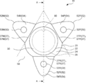
- the support base 20, the piezoelectric film 30, and the elasticity of the positive electrode 50P, the negative electrode 50M, and the reference electrode 50R as an example of the electrocardiographic electrode are arranged respectively. It includes sex members 52P, 52M, 52R.
- the support base 20 includes an opening 22, a first contact surface 24 extending around the opening 22 and in contact with the living body 12, and a back surface 26 provided on the side opposite to the first contact surface 24. It has a first contact surface 24 and a side surface 25 connected to the back surface 26. Further, the support base 20 has a constricted portion 28 having a diameter smaller than that of the first contact surface 24 and the back surface 26 on the side surface 25. Further, the support base 20 is made of a member harder than the elastic member 52 described later.
- the support base 20 has an output terminal 80 on the side surface 25.
- the output terminal 80 is a terminal that outputs a signal indicating a biological sound (adjustment signal S3 described later).
- the output terminal 80 includes, for example, an earphone jack to which the terminal of the earphone 14 for listening to the biological sound acquired by the stethoscope 10 is connected.
- the output terminal 80 is preferably arranged on the back surface 26 side of the constricted portion 28 on the side surface 25. With such a configuration, when the user holds the constricted portion 28 by hand, the operability can be improved without the hand interfering with the terminal of the earphone 14 connected to the output terminal 80.
- the support base 20 has an input unit 82, a display unit 84, and a charging terminal 86 for charging the battery 96 described later on the back surface 26.
- the input unit 82 is a portion where an operation for adjusting the volume level of the biological sound heard by using the earphone 14 is performed.
- the input unit 82 includes, for example, a dial-type input component. By making the input unit 82 a dial type, it is possible to prevent the user from erroneously operating the input unit 82 as compared with the button type.
- the display unit 84 includes, for example, an LED light and displays the remaining amount of the battery 96 and the like.
- the elastic members 52P, 52M, and 52R have second contact surfaces 54P, 54M, and 54R that come into contact with the living body 12, respectively, and are elastic members connected to the periphery of the support base 20, respectively.
- the elastic members 52P, 52M, and 52R are not distinguished, they are referred to as elastic members 52.
- the second contact surface 54P, 54M, 54R is not distinguished, it is referred to as the second contact surface 54.
- the elastic member 52 includes, for example, an elastomer material, a silicone resin, a silicone rubber, a urethane rubber, a natural rubber, a styrene butadiene rubber, a chloroprene rubber, an acrylic nitrile rubber, a butyl rubber, an ethylene propylene rubber, a fluorine rubber, and a clothosulfonated polyethylene rubber. It may be configured to include any one.
- the elasticity member 52 containing these materials has higher durability but lower flexibility as the thickness increases and the Young's modulus increases. When the flexibility is reduced, when the elastic member 52 is pressed against the living body 12, the hardness may cause discomfort.
- the elastic member 52 preferably has a thickness of 0.5 mm or more and 50 mm or less.
- the thickness is more preferably 3 mm or more and 30 mm or less, and most preferably the thickness is 5 mm or more and 20 mm or less.
- the elastic member 52 preferably has a Young's modulus of 0.2 MPa or more and 50 MPa or less. It is more preferable that Young's modulus is 0.2 MPa or more and 10 MPa or less.
- the positive electrode 50P, the negative electrode 50M, and the reference electrode 50R for measuring the reference level are arranged on the second contact surfaces 54P, 54M, and 54R, respectively. That is, each of the three electrocardiographic electrodes of the positive electrode 50P, the negative electrode 50M, and the reference electrode 50R is arranged around the piezoelectric film 30.
- an electrocardiographic electrode 50 when the positive electrode 50P, the negative electrode 50M, and the reference electrode 50R are not particularly distinguished, they are referred to as an electrocardiographic electrode 50.
- the electrocardiographic electrode 50 is removable from the elastic member 52.
- the electrocardiographic electrode 50 and the elastic member 52 may be provided with a pair of coupling members (for example, a snap coupling member).
- at least one of the electrocardiographic electrode 50 and the elastic member 52 may be provided with a detachable adhesive member on the surface in contact with each other. Since the electrocardiographic electrode 50 is removable, the electrocardiographic electrode 50 can be replaced as appropriate.
- the electrocardiographic electrode 50 a commercially available disposable type electrocardiographic electrode can be used.
- the electrocardiographic electrode 50 preferably has adhesiveness on the surface in contact with the living body 12. Specifically, the adhesive strength measured by the following measuring method is preferably 0.25 N / mm (3 N / 12 mm) or less.
- test piece with a width of 12 mm is attached to the end of the test plate, and immediately using a crimping roller, the test piece is attached to the test plate so that the other end side of the test piece remains as a pulling allowance while crimping at a speed of 1 mm / s. It was.
- the test plate is set in a testing machine (AGS-X (manufactured by Shimadzu Corporation) or ZTA (manufactured by Imada Co., Ltd.)), and the test piece is peeled off from the test plate at a speed of 10 mm / s, and the measured value (N). ) Stabilized and the average of the measured values from the end of peeling to the end of peeling was calculated and used as the value of adhesive strength.
- AGS-X manufactured by Shimadzu Corporation
- ZTA manufactured by Imada Co., Ltd.
- the electrocardiogram detected by the electrocardiographic electrode 50 and the biological sound detected by the piezoelectric film 30 can be obtained by contacting the stethoscope 10 with the living body 12 without moving the stethoscope 10 for a certain period of time. Detects biological sounds. Therefore, since the electrocardiographic electrode 50 has adhesiveness on the surface in contact with the living body 12, the stethoscope 10 can be fixed to the living body 12, and the stethoscope 10 can be prevented from moving easily. .. That is, since the electrocardiographic electrode 50 has adhesiveness, it is possible to suppress a decrease in the detection efficiency of the electrocardiogram and the biological sound when the stethoscope 10 is brought into contact with the living body 12.
- the electrocardiographic electrode 50 In order for the electrocardiographic electrode 50 to detect the electrocardiogram of the living body 12 with sufficient accuracy, it is preferable that the electrocardiographic electrode 50 has a predetermined area. Therefore, it is preferable that the area of each of the second contact surfaces 54 of the elastic member 52 on which the electrocardiographic electrode 50 is arranged is 100 mm 2 or more. By setting the area of the second contact surface 54 to the area in the above range, the electrocardiographic electrode 50 having a sufficient area can be arranged, and the electrocardiogram can be detected with sufficient accuracy.
- the electrocardiographic signal S5 (details will be described later) is output depending on the positional relationship between the heart of the living body 12 and the positive electrode 50P, the negative electrode 50M, and the reference electrode 50R.
- the orientation changes.
- the electrocardiographic electrode 50 is directed so that the reference electrode 50R faces the head side of the living body 12 and the positive electrode 50P and the negative electrode 50M face the leg side of the living body 12. It is assumed that it is required to determine the orientation of the living body 12 with respect to the living body 12. Therefore, it is desired that the user can easily determine which function the three electrocardiographic electrodes 50 have.
- the output terminal 80 is arranged on the axis AA passing through the center of one predetermined electrocardiographic electrode 50 out of the three electrocardiographic electrodes 50 and the center of the piezoelectric film 30.
- the electrocardiographic electrode 50 arranged on the axes AA is the reference electrode 50R.
- the positive electrode 50P and the negative electrode 50M are arranged around the piezoelectric film 30 at positions symmetrical with respect to the axes AA.
- the user can easily determine which electrocardiographic electrode 50 is the reference electrode 50R based on the position of the output terminal 80. Therefore, the operability of the user can be improved.
- the output terminal 80 is not limited to the one arranged at a position facing the reference electrode 50R with the piezoelectric film 30 interposed therebetween.
- the output terminal 80 may be located on the shafts AA and closest to the reference electrode 50R.
- the electrocardiographic electrode 50 arranged on the axes AA is not limited to the reference electrode 50R. It suffices if the three electrocardiographic electrodes 50 can be distinguished from each other in terms of the positional relationship with the output terminal 80, and the positive electrode 50P and the negative electrode 50M may be used as the electrocardiographic electrodes 50 arranged on the axes AA. ..
- FIGS. 3 to 5 are cross-sectional views taken along the line AA of FIG. 3, FIG. 4 shows a case where the stethoscope 10 is not pressed against the living body 12, and FIG. 5 shows a case where the stethoscope 10 is pressed against the living body 12. ..
- the electrocardiographic electrode 50 in order for the electrocardiographic electrode 50 to detect the electrocardiogram of the living body 12 with sufficient accuracy, the electrocardiographic electrode 50 needs to have a predetermined area. In addition, by arranging the three electrocardiographic electrodes 50 sufficiently apart, the influence of the myoelectricity of the living body 12 can be eliminated, and the electrocardiogram can be detected at a high SN ratio.
- the support base 20 has three first connecting sides 27P, 27M, 27R connected to the elastic members 52P, 52M, 52R, respectively, as the sides defining the first contact surface 24.
- Each of the first connecting sides 27P, 27M, and 27R constitutes at least a part of each side of the triangle 58 including the first contact surface 24.
- the first connection sides 27P, 27M, and 27R are not particularly distinguished, they are referred to as the first connection side 27.
- the elastic member 52P has a second connecting side 57P connected to the first connecting side 27P of the support base 20 as a side defining the second contact surface 54P.
- the length of the second connecting side 57P is equal to the length of the first connecting side 27P.
- the elastic member 52M has a second connecting side 57M connected to the first connecting side 27M of the support base 20 as a side defining the second contact surface 54M.
- the length of the second connecting side 57M is equal to the length of the first connecting side 27M.
- the elastic member 52R has a second connecting side 57R connected to the first connecting side 27R of the support base 20 as a side defining the second contact surface 54R.
- the length of the second connecting side 57R is equal to the length of the first connecting side 27R.
- the second connection side 57 is "equal" to the length of the first connecting side 27, and the length is stably connected to the first connecting side 27, not only when they are completely equal. It suffices to have a length of about ⁇ 10, for example, a difference of about ⁇ 10% may be obtained.
- the elastic member 52 has a shape that tapers toward a direction away from the second connecting side 57.
- the elastic member 52R has an obtuse angle ⁇ formed by the second contact surface 54R and the first contact surface 24. Is. The same applies to the elastic members 52P and 52M.
- the stethoscope 10 applies a pressure to press the first contact surface 24 of the support base 20 against the living body 12, so that the first contact surface 24 and the elastic member 52R come into second contact with each other.
- Each of the surfaces 54R is configured to extend within the same surface. The same applies to the elastic members 52P and 52M.
- the elastic member 52 has a Young's modulus of 0.2 MPa or more and 50 MPa or less, and the support base 20 is made of a member harder than the elastic member 52. Therefore, in the elastic member 52, each of the first contact surface 24 and the second contact surface 54 extends in the same plane starting from the first connection side 27 and the second connection side 57. Can turn to. At this time, since the urging force acts in the direction of pressing the second contact surface 54 against the living body 12, the electrocardiographic electrode 50 and the living body 12 can be brought into close contact with each other, and the electrocardiogram can be detected at a high SN ratio. ..
- the triangle 58 is not limited to an equilateral triangle as shown in FIG.
- it may be an isosceles triangle in which the reference electrode 50R is arranged on the base and the positive electrode 50P and the negative electrode 50M are arranged on the equal side.
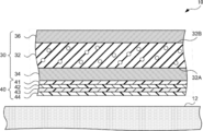
- FIG. 6 is an enlarged schematic view of a part of the piezoelectric film 30 and the protective layer 40 in order to show the configuration of the piezoelectric film 30 and the protective layer 40.
- the piezoelectric film 30 is supported by the support base 20 in a state where the surface exposed from the opening 22 is curved in a convex shape. Further, the surface exposed from the opening 22 of the piezoelectric film 30 projects with respect to the first contact surface 24.
- the piezoelectric film 30 Since the surface exposed from the opening 22 of the piezoelectric film 30 is curved in a convex shape, the piezoelectric film 30 expands and contracts in the in-plane direction as compared with the case where the piezoelectric film 30 is provided in a flat shape. It can be made larger. That is, by supporting the piezoelectric film 30 on the support base 20 in a state where the surface exposed from the opening 22 is curved in a convex shape, the amplitude of the voltage detected by the piezoelectric film 30 can be increased, and a high SN ratio can be obtained. It is possible to collect sound at.
- the piezoelectric film 30 may be directly connected to a part of the support base 20, or may be connected to the support base 20 via another member such as an adhesive. Further, the piezoelectric film 30 has elasticity and flexibility to the extent that it does not crack when pressed against the living body 12.
- a cushion material 38A is filled between the piezoelectric film 30 and the support base 20, and the piezoelectric film 30 is supported by the cushion material 38A so as to be curved in a convex shape.
- the cushion material 38A has an appropriate elasticity, supports the piezoelectric film 30, and gives a constant mechanical bias to the entire surface of the piezoelectric film 30.
- the vibration in the thickness direction generated in the piezoelectric film 30 can be converted into the expansion / contraction motion in the in-plane direction of the piezoelectric film 30, and the electric charge generation efficiency can be improved.
- a stethoscope 10 having an appropriate repulsive force can be realized.
- the material of the cushion material 38A may be any material that has appropriate elasticity, does not prevent the piezoelectric film 30 from vibrating, and is preferably deformed.
- alpha gel registered trademark
- silicone used as a main raw material
- wool felt containing polyester fibers such as rayon and polyethylene terephthalate (PET)
- fiber materials such as glass wool, and polyurethane.
- PTT polyethylene terephthalate
- gas 38B may be filled instead of the cushion material 38A.
- the piezoelectric film 30 has two main surfaces facing each other, a first main surface 32A which is the main surface on the side of the living body 12, and a main surface opposite to the side of the living body 12. It includes a piezoelectric layer 32 having a second main surface 32B, a first electrode 34 provided on the first main surface 32A, and a second electrode 36 provided on the second main surface 32B. ..
- the piezoelectric layer 32 expands and contracts in the in-plane direction in response to the biological sound emitted from the living body 12, and generates a voltage between the first electrode 34 and the second electrode 36 in response to the expansion and contraction in the in-plane direction.
- the piezoelectric layer 32 it is possible to use a polymer composite piezoelectric body in which the piezoelectric particle 33 is dispersed in a matrix made of a polymer material.
- the piezoelectric particles 33 may be uniformly dispersed in the matrix with regularity, or may be irregularly dispersed in the matrix.
- the matrix is viscoelastic at room temperature, for example, cyanoethylated polyvinyl alcohol (cyanoethylated PVA), polyvinyl acetate, polyvinylidene chloride core acrylonitrile, polystyrene-vinyl polyisoprene block copolymers, polyvinyl methyl ketone, polybutyl methacrylate and the like.
- a polymer material having is preferable.
- the piezoelectric particle 33 is a piezoelectric particle, and is preferably a ceramic particle having a perovskite-type crystal structure.
- a ceramic particle having a perovskite-type crystal structure For example, lead zirconate titanate, lead lanthanate zirconate titanate, barium titanate, and a solid solution of barium titanate and bismuth ferrite are exemplified.
- the piezoelectric layer 32 having such a configuration causes dielectric polarization in the thickness direction of the piezoelectric layer 32.
- the piezoelectric layer 32 that causes dielectric polarization in this way, the piezoelectric layer 32 generates a positive charge on the side of the second main surface 32B and a negative charge on the side of the first main surface 32A. It is preferable to arrange. It is known that the living body 12 is usually positively charged in many cases. Therefore, by arranging the piezoelectric layer 32 so as to generate a negative charge on the side of the first main surface 32A, which is the surface on the side in contact with the living body 12, the living body sound can be detected efficiently.
- an organic piezoelectric film such as polyvinylidene fluoride (PVDF), vinylidene-ethylene trifluoride copolymer (P (VDF-TrFE)), or polylactic acid may be used.
- PVDF polyvinylidene fluoride
- PVDF-TrFE vinylidene-ethylene trifluoride copolymer
- polylactic acid polylactic acid
- an organic material such as a polymer electret material containing a polymer as a main component described in JP-A-2018-191394, JP-A-2014-233688, and JP-A-2017-12270 is used. You may.
- polyimide polytetrafluoroethylene, polypropylene, PTFE (polytetrafluoroethylene (tetrafluoride)), PFA (tetrafluoroethylene / perfluoroalkyl vinyl ether copolymer), FEP (tetrafluoroethylene / hexafluoropropylene)
- Teflon registered trademark
- polymer 4 fluoride
- AF amorphous fluoropolymer
- polyethylene polyethylene
- COCs cycloolefin polymer
- the piezoelectric layer 32 when PVDF is used as the piezoelectric layer 32 instead of the polymer composite piezoelectric material, dielectric polarization occurs in the in-plane direction.
- the SN ratio may be lower than that of the polymer composite piezoelectric material in which dielectric polarization occurs in the thickness direction.
- the first electrode 34 and the second electrode 36 detect the expansion and contraction in the in-plane direction of the piezoelectric layer 32 as a voltage.
- the thickness of the first electrode 34 and the second electrode 36 is not particularly limited, but is preferably thin in order to ensure the flexibility of the piezoelectric film 30, and is preferably 1 ⁇ m or less, for example.
- the thicknesses of the first electrode 34 and the second electrode 36 may be the same or different.
- the materials of the first electrode 34 and the second electrode 36 are a thin film of copper (Cu) and aluminum (Al) formed by vacuum deposition in order to ensure the flexibility of the piezoelectric film 30, and a conductive polymer. Etc. are preferable.
- various conductors may be used as the material of the first electrode 34 and the second electrode 36.
- C, Pd, Fe, Sn, Ni, Pt, Au, Ag, Cr and Mo, alloys thereof and the like may be used.
- a transparent conductive film such as indium tin oxide (ITO), indium zinc oxide (IZO), tin oxide, and zinc oxide may be used.
- an organic conductor such as a conductive polymer may be used.
- the method of forming the electrode is also not particularly limited, and various methods such as film formation by a vapor phase deposition method (vacuum film deposition method) such as vacuum deposition and sputtering, screen printing, and a method of pasting a foil formed of the above materials are used. A known method of is used.
- the size of at least one of the first electrode 34 and the second electrode 36 may be smaller than that of the piezoelectric layer 32.
- the first electrode 34 is preferably provided only in the central portion of the first main surface 32A.
- the first electrode 34 may function as an antenna and take in electromagnetic noise from the outside in addition to the function of detecting the biological sound emitted from the living body 12. In order to suppress the capture of electromagnetic noise, it is preferable to reduce the size of the first electrode 34 within a range in which it is difficult to capture electromagnetic noise and biological sound can be sufficiently detected.
- the piezoelectric film 30 Since the surface of the piezoelectric film 30 exposed from the opening 22 is convexly curved and protrudes with respect to the first contact surface 24, the piezoelectric film 30 is different from the living body 12 as compared with the case where it is provided in a flat shape. If it comes into direct contact, it will be easily damaged. Therefore, it is preferable to arrange the protective layer 40 on the surface of the piezoelectric film 30 on the side in contact with the living body 12. By arranging the protective layer 40 on the surface of the piezoelectric film 30 on the side in contact with the living body 12, damage to the piezoelectric film 30 can be prevented.
- the protective layer 40 preferably has an acoustic impedance between the acoustic impedance of the living body 12 and the acoustic impedance of the piezoelectric film 30 in order to alleviate the difference in acoustic impedance between the living body 12 and the piezoelectric film 30. ..
- FIG. 9 is a graph obtained by measuring the SN ratio of the sound signal S2 (details will be described later) output from the stethoscope 10 when the acoustic impedance of the protective layer 40 is changed.
- the horizontal axis shows the acoustic impedance (MRayls) of the protective layer 40
- the vertical axis shows the SN ratio (dB) of the sound signal S2.
- the acoustic impedance of the living body 12 is 1.3 to 1.5 MRayls
- the acoustic impedance of the piezoelectric film 30 is 5.0 to 10.0 MRayls.
- the acoustic impedance of the protective layer 40 is 1.3 MRayls or more and 5.0 MLayls or less between the acoustic impedance of the living body 12 and the acoustic impedance of the piezoelectric film 30, it is output from the stethoscope 10 as shown in FIG.
- the SN ratio of the sound signal S2 could be stably set to 60 dB or more.
- the protective layer 40 in which the acoustic impedance is matched between the living body 12 and the piezoelectric film 30, it is possible to suppress the reflection of sound, and it is possible to collect sound with a high SN ratio. ..
- the protective layer 40 is any one of elastomer material, silicone resin, silicone rubber, urethane rubber, natural rubber, styrene butadiene rubber, chloroprene rubber, acrylic nitrile rubber, butyl rubber, ethylene propylene rubber, fluororubber and crososulfonated polyethylene rubber. It is preferable to use one. Since the protective layer 40 is directly pressed against the living body 12, it is desired that the protective layer 40 is a material that does not cause discomfort due to coldness or hardness to the living body 12. By using the above material, it is possible to suppress the occurrence of discomfort even when the protective layer 40 is pressed against the living body 12.
- the protective layer 40 Since the protective layer 40 is directly pressed against the living body 12, it is desired to have abrasion resistance. Therefore, it is preferable that the protective layer 40 has a measured value of 50 or more and 100 or less in a hardness test using a type A durometer conforming to ASTM D2240. The hardness measured by a durometer of another standard and another measuring method may indicate a hardness equivalent to the hardness in the above test method. By setting the protective layer 40 to a hardness in the above range, it is possible to have appropriate wear resistance for use as a stethoscope.
- the thickness of the protective layer 40 having the above-mentioned material and hardness may be appropriately set according to the performance, handleability, mechanical strength, and the like required for the piezoelectric film 30. Specifically, it may be about 500 ⁇ m.
- the surface of the protective layer 40 in contact with the living body 12 is roughened. Since the protective layer 40 is directly pressed against the living body 12, it is desirable that the protective layer 40 be easily peeled off from the skin of the living body 12.
- the roughening treatment method is not particularly limited, and various known methods such as mechanical roughening treatment, electrochemical roughening treatment, and chemical roughening treatment may be used.
- the roughness of the surface of the protective layer 40 in contact with the living body 12 is preferably such that the arithmetic average roughness Ra is 0.1 ⁇ m or more and 100 ⁇ m or less, and 0.1 ⁇ m or more and 10 ⁇ m or less. More preferred. By making the protective layer 40 rough in the above range, it can be easily peeled off from the skin of the living body 12.
- the protective layer 40 may be a layer in which the acoustic impedance is inclined so that the acoustic impedance becomes lower toward the side in contact with the living body 12. Further, the protective layer 40 may be composed of a plurality of layers laminated so that the acoustic impedance becomes lower toward the layer on the side in contact with the living body 12. For example, as shown in FIG. 10, when the protective layer 40 is composed of four layers, the acoustic impedance may be lowered in the order of the protective layers 41, 42, 43, 44. In this case, the materials of the plurality of layers may be different, and a material composed of at least one of the above-mentioned materials may be used. By having such a configuration of the protective layer 40, the difference in acoustic impedance between adjacent substances can be made smaller, and sound can be collected at a higher SN ratio.
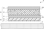
- the protective layer 40 has a surface in contact with the living body 12 made of a silicone resin, and the silicone resin has a siloxane skeleton as a main chain skeleton and a methyl group, a vinyl methyl group and a phenyl methyl group as hydrophobic side chains. It may have at least one of.
- the surface of the living body 12 may be wet due to sweat or the like. Since the protective layer 40 is directly pressed against the living body 12, it is desired that at least the surface in contact with the living body 12 is a material that is not denatured by water. Therefore, for example, as shown in FIG.
- the protective layer 40 is composed of a protective layer 46 whose acoustic impedance is matched, and a protective layer 47 which is a surface in contact with the living body 12 and is made of a hydrophobic material. It may be configured. Since the surface in contact with the living body 12 is hydrophobic, it is possible to prevent the protective layer 40 and the piezoelectric film 30 from being denatured even when the protective layer 40 is pressed against the wet living body 12.
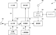
- the stethoscope 10 includes a piezoelectric film 30, an electrocardiographic electrode 50, an output terminal 80, an input unit 82, a display unit 84, and a charging terminal 86. Further, the stethoscope 10 includes an output unit 60, a processing unit 90, a communication unit 92, a power unit 94, and a battery 96.
- the output unit 60, the processing unit 90, the communication unit 92, the power unit 94, and the battery 96 may be accommodated in the accommodating unit 29, which is the space provided by the support base 20 (see FIG. 4), and are provided outside the support base 20. It may be the one that can be used.
- the piezoelectric film 30 detects the vibration generated by the biological sound generated from the living body 12, and outputs the vibration signal S1 to the output unit 60 based on the vibration. Specifically, when the surface of the living body 12 is vibrated by the biological sound generated from the living body 12, when the piezoelectric film 30 is brought into contact with the living body 12, the piezoelectric film 30 also vibrates according to the vibration. The piezoelectric film 30 detects vibration as a voltage generated between the first electrode 34 and the second electrode 36, and outputs the detected voltage as a vibration signal S1 to the output unit 60.
- the input unit 82 receives the adjustment input of the level of the sound signal S2 output from the output unit 60, which will be described later, and outputs the adjustment input signal S4 indicating the received adjustment input information to the output unit 60.
- the output unit 60 outputs the sound signal S2 to the processing unit 90 based on the vibration signal S1. Further, the output unit 60 adjusts the level of the sound signal S2 according to the level change of the vibration signal S1 and the adjustment input signal S4, and outputs the adjustment signal S3 to the output terminal 80. The output terminal 80 outputs the adjustment signal S3 to the outside.
- the electrocardiographic electrode 50 detects the electrocardiogram of the living body 12. Specifically, by bringing the electrocardiographic electrode 50 into contact with the vicinity of the heart of the living body 12, the potential on the body surface of the living body 12 is detected and output as an electrocardiographic signal S5 to the processing unit 90.
- the processing unit 90 performs predetermined processing on the data based on the sound signal S2 and the electrocardiographic signal S5, and outputs the processed data to the communication unit 92.
- the processing unit 90 may include an amplifier circuit, a filter circuit, and the like to amplify the sound signal S2 and the electrocardiographic signal S5, or extract a specific frequency. Further, the data based on the sound signal S2 and the electrocardiographic signal S5 may be output as analog data or digital data.
- the processing unit 90 may be composed of, for example, a microcomputer including a CPU (Central Processing Unit) 60, a ROM (Read Only Memory), a RAM (Random Access Memory), and the like.
- the communication unit 92 is provided with a wired or wireless communication means, and transmits biological sound and electrocardiographic data to an external device.
- the communication means may be, for example, Bluetooth (registered trademark), infrared communication, or the like, and the external device may be, for example, a personal computer, a smartphone, or the like.
- the power unit 94 charges the battery 96 with the electric power supplied from the charging terminal 86. Further, the power unit 94 supplies the electric power charged in the battery 96 to the output unit 60, the display unit 84, the processing unit 90, and the communication unit 92.
- the processing unit 90 acquires information indicating the remaining battery level of the battery 96 via the power unit 94, and controls such as turning on, extinguishing, and blinking the LED light of the display unit 84 based on the acquired information. You may. In this case, the user can grasp the remaining battery level of the battery 96 from the light emitting state of the LED light.
- the display unit 84 may be controlled when the sound signal S2 and the electrocardiographic signal S5 are normally acquired. In this case, the user can grasp the acquisition state of the sound signal S2 and the electrocardiographic signal S5 depending on the display mode of the display unit 84.
- the output unit 60 includes a buffer 61, a filter circuit 62, amplifiers 63 and 65, and an ALC (Automatic Level Control) circuit 64.
- ALC Automatic Level Control
- the vibration signal S1 detected by the piezoelectric film 30 is input to the filter circuit 62 via the buffer 61, noise is cut by the filter circuit 62, amplified by the amplifier 63, and used as the sound signal S2 by the processing unit 90 and the ALC. It is output to the circuit 64.
- the filter circuit 62 is, for example, a low-pass filter.
- the piezoelectric film 30 vibrates greatly, and a steep noise (spike noise) may be mixed in the vibration signal S1. .. If the spike noise is output as the sound signal S2 from the output terminal 80 as it is, the sound heard from the earphone connected to the output terminal 80 becomes a jarring sound. Therefore, it is desirable to reduce spike noise by the ALC circuit 64.
- the adjustment input signal S4 and the sound signal S2 from the input unit 82 are input to the ALC circuit 64.
- the ALC circuit 64 is, for example, a Schottky barrier diode for detecting spike noise from the sound signal S2, a capacitor for smoothing the sound signal S2, and a MOSFET (Metal-Oxide) driven when spike noise is detected. -Semiconductor Field-Effect Transistor) and the like may be included.
- the ALC circuit 64 uses these elements to reduce spike noise and adjust the level of the sound signal S2 based on the adjustment input signal S4.
- the spike noise is reduced by the ALC circuit 64, and the level-adjusted sound signal S2 is amplified by the amplifier 65 and output to the output terminal 80 as the adjustment signal S3.
- the piezoelectric film 30 is supported by the support base 20 in a state where the surface exposed from the opening 22 is convexly curved, and the piezoelectric film 30 is supported.
- a protective layer 40 having an acoustic impedance between the acoustic impedance of the living body 12 and the acoustic impedance of the piezoelectric film 30 is provided on the surface of the film 30 on the side in contact with the living body 12. Therefore, the biological sound can be detected with a high SN ratio.
- the output terminal 80 is on the center of one of the three electrocardiographic electrodes 50 and the center of the piezoelectric film 30. It is located in. Therefore, the operability of the user can be improved.
- the elastic member 52 has an obtuse angle with the first contact surface 24, and is among the sides defining the second contact surface 54. It is an elastic member connected to each of the first connecting sides 27 at the second connecting side 57 having a length equal to that of the first connecting side 27. Therefore, the electrocardiographic electrodes 50 can have a predetermined area while suppressing the increase in the size of the stethoscope 10 itself, and the three electrocardiographic electrodes 50 can be arranged sufficiently apart. That is, it is possible to detect the electrocardiogram with a high SN ratio while improving the operability of the user.
- FIGS. 14 and 15 elements equivalent to the elements described in the first exemplary embodiment are designated by the same reference numerals, and detailed description thereof will be omitted.
- the piezoelectric film 30 When the piezoelectric film 30 is supported by the support base 20 in a convexly curved state as in the stethoscope 10 according to the first exemplary embodiment, when the stethoscope 10 is pressed against the living body 12, the piezoelectric film A portion near the outer circumference of the living body 12 may float from the surface of the living body 12. For example, when a patient who does not have specialized skills in telemedicine or the like uses the stethoscope 10, the stethoscope 10 cannot be pressed vertically against the living body 12, or the stethoscope 10 is pressed against the living body 12 with sufficient pressure. It can happen that they are not pressed. When the piezoelectric film 30 is in a floating state, the piezoelectric film 30 can easily detect external sounds such as environmental sounds and human voices (hereinafter referred to as external sounds) as noise, and the SN ratio is lowered.
- external sounds environmental sounds and human voices
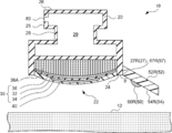
- the stethoscope 10 according to the present exemplary embodiment has the configuration of the stethoscope 10 according to the first exemplary embodiment and the outer periphery of the portion exposed from the opening 22 of the piezoelectric film 30.
- a sound insulating member 70 that surrounds the film and shields external sound transmitted to the piezoelectric film 30 is further provided. Further, the tip of the sound insulating member 70 projects from the convexly curved surface of the piezoelectric film 30.
- the protruding height of the sound insulating member 70 is preferably 1 mm or more.
- the sound insulating member 70 has elasticity enough to compress and deform the entire surface of the piezoelectric film 30 exposed from the opening 22 so that it can come into contact with the living body 12 when the stethoscope 10 is pressed vertically against the living body 12. ..
- the sound insulating member 70 preferably has a high effect of absorbing external sound, such as a fiber-based material such as glass wool and a foam material such as urethane foam.
- FIG. 15 shows a state in which the stethoscope 10 according to this exemplary embodiment is pressed against the living body 12.
- the sound insulating member 70 is compressed according to the pressed pressure.
- the degree of compression of the sound insulation member 70 is large in the portion where the pressure is large, and the compression of the sound insulation member 70 is in the portion where the pressure is small. The degree of is small.
- the piezoelectric film 30 makes an external sound. Can be suppressed from being detected.
- a sound insulating member that surrounds the outer periphery of the portion exposed from the opening 22 of the piezoelectric film 30 and shields the external sound transmitted to the piezoelectric film 30. 70 is further provided. Therefore, when the stethoscope 10 is pressed against the living body 12, the piezoelectric film 30 can be surrounded by the sound insulating member 70, and the piezoelectric film 30 can prevent the external sound from being detected as noise. Biological sounds can be detected with a high SN ratio.
- the stethoscope 10 is not limited to the living body 12 as the object to be measured, and the object to be measured may be a machine, piping, or the like. That is, by detecting the sound generated from the machine, the pipe, or the like as the sound generated from the object to be measured, it can be used for detecting an abnormality of the machine or the pipe.
Abstract
被測定物に接触する第1の接触面を有し、前記第1の接触面を画定する辺の少なくとも一部である3つの第1の接続辺の各々が、前記第1の接触面を内包する三角形の各辺の少なくとも一部である支持台と、前記第1の接触面とのなす角が鈍角であり、かつ前記被測定物に接触する第2の接触面をそれぞれ有し、前記第2の接触面を画定する辺のうち前記第1の接続辺と等しい長さである第2の接続辺において、前記第1の接続辺の各々に接続された弾力性を有する3つの弾力性部材と、前記第2の接触面のそれぞれに配置され、前記被測定物の心電を検出する3つの心電電極と、を備える聴診器。
Description
本開示は、聴診器に関する。特に、被測定物の心電を検出する心電電極を備え、検出した音及び心電をデータとして出力することができる電子聴診器に関する。
従来、生体内部で発生する心音及び血流音等の音(以下、生体音という)を増幅させて聴くことができ、被測定物の心電を検出する心電電極を備えた聴診器について、以下の技術が知られている。
例えば、特開2012-55354号公報には、心音波形を記録するためのマイクロフォンと、心電図を記録するための固定電極及び回転アームに取付けられた可動電極と、を有する電気聴診器が記載されている。
特開2017-170112号公報には、チェストピース及びマイクロフォンからなる聴診器部と、チェストピースの人体への接触面と同じか、当該接触面よりも若干人体から離れる側に、人体へ接触する面が形成された心電図測定用電極と、を有する聴診器が記載されている。
特開2012-55354号公報には、身体音を検知する聴音検知部と、一端が聴音検知部に連通され、他端から身体音を聴診するチューブと、聴音検知部に設けられ心臓の拍動に伴う電位を検知する心電検知部と、心電検知部により検知された電位を無線信号に変換して送信するコントロールユニットと、を有する診断装置が記載されている。
ところで、心電電極は、機能の異なる3つの心電電極を含む場合がある。この場合、それぞれの心電電極が所定の面積を有し、3つの心電電極を十分に離して配置することで、被測定物の筋電の影響を排除することができ、心電を高いSN比(Signal to Noise ratio)で検出することができる。
しかしながら、上記の各特開2012-55354号公報、特開2017-170112号公報、及び特開2012-55354号公報に記載の聴診器において、心電電極の面積を大きくし、3つの心電電極間の距離を離すと、聴診器そのものの大きさが大きくなり、ユーザの操作性が低下する。
本開示は、ユーザの操作性の低下を抑制しつつ、心電を高いSN比で検出できる聴診器を提供する。
本開示の第1の態様は、聴診器であって、被測定物に接触する第1の接触面を有し、第1の接触面を画定する辺の少なくとも一部である3つの第1の接続辺の各々が、第1の接触面を内包する三角形の各辺の少なくとも一部である支持台と、第1の接触面とのなす角が鈍角であり、かつ被測定物に接触する第2の接触面をそれぞれ有し、第2の接触面を画定する辺のうち第1の接続辺と等しい長さである第2の接続辺において、第1の接続辺の各々に接続された弾力性を有する3つの弾力性部材と、第2の接触面のそれぞれに配置され、被測定物の心電を検出する3つの心電電極と、を備える。
本開示の第2の態様は、上記第1の態様において、支持台が、第1の接触面に開口部を有し、開口部から表面の一部が露出した状態で支持台に支持され、被測定物から発生される音によって生じる振動を検出する検出部を更に備えていてもよい。
本開示の第3の態様は、上記態様において、第2の接触面の各々の面積が100mm2以上であってもよい。
本開示の第4の態様は、上記態様において、弾力性部材の厚みが0.5mm以上、50mm以下であってもよい。
本開示の第5の態様は、上記態様において、弾力性部材のヤング率が0.2MPa以上、50MPa以下であってもよい。
本開示の第6の態様は、上記態様において、弾力性部材が、エラストマー材料、シリコーン樹脂、シリコーンゴム、ウレタンゴム、天然ゴム、スチレンブタジエンゴム、クロロプレンゴム、アクリルニトリルゴム、ブチルゴム、エチレンプロピレンゴム、フッ素ゴム及びクロソスルホン化ポリエチレンゴムのうち何れか1つを含んで構成されるものであってもよい。
本開示の第7の態様は、上記態様において、支持台が、弾力性部材よりも硬い部材で構成されていてもよい。
本開示の第8の態様は、上記態様において、弾力性部材が、第2の接続辺から離れる方向に向かって先細りする形状であってもよい。
本開示の第9の態様は、上記態様において、第1の接触面を被測定物に押し当てる押圧を加えることで、第1の接触面と第2の接触面の各々とが同一面内に延在するように構成されていてもよい。
本開示の第10の態様は、上記態様において、3つの心電電極が、それぞれプラス電極、マイナス電極及び基準レベルを測定するリファレンス電極であってもよい。
上記態様によれば、本開示の聴診器は、ユーザの操作性の低下を抑制しつつ、心電を高いSN比で検出することができる。
以下、図面を参照して、本開示の技術を実施するための形態例を詳細に説明する。以下、被測定物の一例として生体12を用い、被測定物から生じる音の一例として生体音を用いて説明する。生体音としては、例えば、心拍、呼吸音、血流音及び腸音等が挙げられる。また、以下、検出部の一例として圧電フィルム30を用いる。
[第1例示的実施形態]
まず、図1から図3を参照して、本例示的実施形態に係る聴診器10の構成について説明する。図1から図3に示すように、聴診器10は、支持台20と、圧電フィルム30と、心電電極の一例としてのプラス電極50P、マイナス電極50M及びリファレンス電極50Rがそれぞれに配置された弾力性部材52P、52M、52Rと、を備える。
まず、図1から図3を参照して、本例示的実施形態に係る聴診器10の構成について説明する。図1から図3に示すように、聴診器10は、支持台20と、圧電フィルム30と、心電電極の一例としてのプラス電極50P、マイナス電極50M及びリファレンス電極50Rがそれぞれに配置された弾力性部材52P、52M、52Rと、を備える。
支持台20は、開口部22と、開口部22の周囲に延在し、生体12に接触する第1の接触面24と、第1の接触面24と反対側に設けられた背面26と、第1の接触面24と背面26とに接続された側面25と、を有する。また、支持台20は、側面25に第1の接触面24及び背面26よりも径が小さいくびれ部28を有する。また、支持台20は、後述する弾力性部材52よりも硬い部材で構成されている。
支持台20は、側面25に、出力端子80を有する。出力端子80は、生体音を示す信号(後述する調整信号S3)が出力される端子である。出力端子80は、例えば、聴診器10によって取得された生体音を聴取するためのイヤホン14の端子が接続されるイヤホンジャックを含む。出力端子80は、側面25のくびれ部28よりも背面26の側に配置されていることが好ましい。このような構成にすることで、ユーザがくびれ部28を手で持った場合に、出力端子80に接続されたイヤホン14の端子と手が干渉することなく、操作性を向上させることができる。
支持台20は、背面26に、入力部82、表示部84及び後述するバッテリー96を充電するための充電端子86を有する。入力部82は、イヤホン14を用いて聴取される生体音の音量レベルの調整のための操作がなされる部分である。入力部82は、例えば、ダイヤル式の入力部品を含む。入力部82をダイヤル式にすることで、ボタン式と比較して、ユーザが誤って操作してしまうことを抑制することができる。表示部84は、例えば、LEDライトを含み、バッテリー96の残量等を表示する。
弾力性部材52P、52M、52Rは、生体12に接触する第2の接触面54P、54M、54Rをそれぞれ有し、それぞれ支持台20の周囲に接続された弾力性を有する部材である。以下、弾力性部材52P、52M、52Rを区別しない場合は、弾力性部材52という。第2の接触面54P、54M、54Rを区別しない場合は、第2の接触面54という。
弾力性部材52は、例えば、エラストマー材料、シリコーン樹脂、シリコーンゴム、ウレタンゴム、天然ゴム、スチレンブタジエンゴム、クロロプレンゴム、アクリルニトリルゴム、ブチルゴム、エチレンプロピレンゴム、フッ素ゴム及びクロソスルホン化ポリエチレンゴムのうち何れか1つを含んで構成されていてもよい。これらの材料を含んでなる弾力性部材52は、厚みが大きいほど、また、ヤング率が大きいほど、耐久性は向上するが、柔軟性が低下する。柔軟性が低下すると、弾力性部材52を生体12に押し当てた場合、硬さにより不快感を生じる場合がある。
したがって、弾力性部材52は、厚みが0.5mm以上、50mm以下であることが好ましい。厚みが3mm以上、30mm以下であることがさらに好ましく、厚みが5mm以上、20mm以下であることが最も好ましい。また、弾力性部材52は、ヤング率が0.2MPa以上、50MPa以下であることが好ましい。ヤング率が0.2MPa以上、10MPa以下であることがさらに好ましい。弾力性部材52を上記の範囲の厚み及びヤング率にすることで、聴診器として使用するのに適切な耐久性及び柔軟性を有する部材とすることができる。
プラス電極50P、マイナス電極50M及び基準レベルを測定するリファレンス電極50Rは、第2の接触面54P、54M、54Rのそれぞれに配置される。すなわち、プラス電極50P、マイナス電極50M及びリファレンス電極50Rの3つの心電電極の各々が圧電フィルム30の周囲に配置される。以下、プラス電極50P、マイナス電極50M及びリファレンス電極50Rを特に区別しない場合は、心電電極50という。
心電電極50は、弾力性部材52に着脱可能であることが好ましい。例えば、心電電極50及び弾力性部材52に、対となる結合部材(例えば、スナップ結合部材等)を設けてもよい。また、例えば、心電電極50及び弾力性部材52の少なくとも一方の、それぞれが接触する面に着脱可能な程度の粘着部材を設けてもよい。心電電極50が着脱可能であることで、心電電極50を適宜交換することができる。
心電電極50としては、市販のディスポーザブルタイプの心電電極を用いることができる。心電電極50は、生体12と接触する面に、粘着性を有することが好ましい。具体的には、以下の測定方法で測定した粘着力が、0.25N/mm(3N/12mm)以下であることが好ましい。
[180°剥離試験]
幅12mmの試験片の一端を試験板の端に貼り、直ちに圧着ローラを用いて、1mm/sの速さで圧着しながら、試験片の他端側が引っ張り代として残るようにして試験板に貼った。試験板を試験機(AGS-X(株式会社島津製作所製)又はZTA(株式会社イマダ製))にセットして、試験片を10mm/sの速さで試験板から引き剥がし、測定値(N)が安定した後から引き剥がし終了時までの測定値の平均を算出して、粘着力の値とした。
幅12mmの試験片の一端を試験板の端に貼り、直ちに圧着ローラを用いて、1mm/sの速さで圧着しながら、試験片の他端側が引っ張り代として残るようにして試験板に貼った。試験板を試験機(AGS-X(株式会社島津製作所製)又はZTA(株式会社イマダ製))にセットして、試験片を10mm/sの速さで試験板から引き剥がし、測定値(N)が安定した後から引き剥がし終了時までの測定値の平均を算出して、粘着力の値とした。
心電電極50により検出される心電、及び圧電フィルム30(詳細は後述する)により検出される生体音は、聴診器10を一定の期間動かさずに生体12に接触させることで、心電及び生体音を検出する。したがって、心電電極50が生体12と接触する面に粘着性を有することで、聴診器10を生体12に固定することができ、聴診器10が容易に動いてしまうことを抑制することができる。すなわち、心電電極50が粘着性を有することで、聴診器10を生体12に接触させた場合に、心電及び生体音の検出効率が低下することを抑制することができる。
心電電極50が生体12の心電を十分な精度で検出するためには、心電電極50が所定の面積を有することが好ましい。したがって、心電電極50が配置される弾力性部材52は、第2の接触面54の各々の面積が、100mm2以上であることが好ましい。第2の接触面54の面積を上記の範囲の面積にすることで、十分な面積を有した心電電極50を配置することができ、心電を十分な精度で検出することができる。
ここで、本例示的実施形態に係る出力端子80の位置について説明する。心電電極50を生体12に接触させた場合、生体12の心臓と、プラス電極50P、マイナス電極50M及びリファレンス電極50Rとの位置関係によって、出力される心電信号S5(詳細は後述する)の向きは変化する。心電信号S5を規定の向きで出力させるために、例えば、リファレンス電極50Rが生体12の頭部側、プラス電極50P及びマイナス電極50Mが生体12の脚部側に向くように、心電電極50の生体12に対する向きを定めることが要求されることが想定される。したがって、3つの心電電極50が、どの機能をもった電極かをユーザが容易に判断することができることが望まれている。
図3に示すように、出力端子80は、3つの心電電極50のうち1つの所定の心電電極50の中心、及び圧電フィルム30の中心を通る軸A-A上に配置されている。本例示的実施形態において、軸A-A上に配置される心電電極50は、リファレンス電極50Rである。また、プラス電極50P及びマイナス電極50Mは、圧電フィルム30の周囲であって、軸A-Aに対して対称の位置にそれぞれ配置されている。
このような構成にすることで、出力端子80の位置に基づいて、何れの心電電極50がリファレンス電極50Rであるかをユーザが容易に判断することができる。したがって、ユーザの操作性を向上することができる。
なお、出力端子80は、図3に示したように、圧電フィルム30を挟んでリファレンス電極50Rと対向する位置に配置されるものに限らない。例えば、出力端子80は、軸A-Aの上であって、リファレンス電極50Rと最も近い位置に配置されるものであってもよい。
また、軸A-A上に配置される心電電極50は、リファレンス電極50Rに限らない。出力端子80との位置関係で3つの心電電極50の区別をすることができればよく、軸A-A上に配置される心電電極50として、プラス電極50P及びマイナス電極50Mを用いてもよい。
次に、図3から図5を参照して、本例示的実施形態に係る支持台20と弾力性部材52の接続関係について説明する。図4及び図5は、図3のA-A断面図であり、図4は聴診器10を生体12に押し当てていない場合、図5は聴診器10を生体12に押し当てた場合を示す。
心電電極50が生体12の心電を十分な精度で検出するためには、上述したように、心電電極50が所定の面積を有する必要がある。それに加え、3つの心電電極50を十分に離して配置することで、生体12の筋電の影響を排除することができ、心電を高いSN比で検出することができる。
図3に示すように、支持台20は、第1の接触面24を画定する辺として、弾力性部材52P、52M、52Rにそれぞれ接続される3つの第1の接続辺27P、27M、27Rを有する。第1の接続辺27P、27M、27Rの各々は、第1の接触面24を内包する三角形58の各辺の少なくとも一部を構成している。以下、第1の接続辺27P、27M、27Rを特に区別しない場合は、第1の接続辺27という。
弾力性部材52Pは、第2の接触面54Pを画定する辺として、支持台20の第1の接続辺27Pに接続される第2の接続辺57Pを有する。第2の接続辺57Pの長さは、第1の接続辺27Pの長さと等しい。同様に、弾力性部材52Mは、第2の接触面54Mを画定する辺として、支持台20の第1の接続辺27Mに接続される第2の接続辺57Mを有する。第2の接続辺57Mの長さは、第1の接続辺27Mの長さと等しい。同様に、弾力性部材52Rは、第2の接触面54Rを画定する辺として、支持台20の第1の接続辺27Rに接続される第2の接続辺57Rを有する。第2の接続辺57Rの長さは、第1の接続辺27Rの長さと等しい。以下、第2の接続辺57P、57M、57Rを特に区別しない場合は、第2の接続辺57という。ここで、第2の接続辺57の長さが第1の接続辺27の長さと「等しい」長さとは、完全に等しい場合に限らず、第1の接続辺27に安定して接続される程度の長さを有していればよく、例えば±10%程度の差異を有していてもよい。また、弾力性部材52は、第2の接続辺57から離れる方向に向かって先細りする形状である。
図4に示すように、第1の接触面24を生体12に押し当てていない状態において、弾力性部材52Rは、第2の接触面54Rと第1の接触面24とのなす角θが鈍角である。なお、弾力性部材52P、52Mについても同様である。
図5に示すように、聴診器10は、支持台20の第1の接触面24を生体12に押し当てる押圧を加えることで、第1の接触面24と弾力性部材52Rの第2の接触面54Rの各々とが同一面内に延在するように構成されている。なお、弾力性部材52P、52Mについても同様である。
上述したように、弾力性部材52はヤング率が0.2MPa以上、50MPa以下であり、支持台20は弾力性部材52よりも硬い部材で構成されている。したがって、弾力性部材52は、第1の接続辺27及び第2の接続辺57を起点として、第1の接触面24と第2の接触面54の各々とが同一面内に延在するように曲がることができる。このとき、第2の接触面54を生体12に押し付ける方向に付勢力が作用するので、心電電極50と生体12とを密着させることができ、心電を高いSN比で検出することができる。
なお、三角形58は、図3に示したような正三角形に限らない。例えば、底辺にリファレンス電極50Rが配置され、等辺にプラス電極50P及びマイナス電極50Mが配置された二等辺三角形であってもよい。
次に、図4及び図6から図11を参照して、本例示的実施形態に係る圧電フィルム30及び保護層40の構成について説明する。図6は、圧電フィルム30及び保護層40の構成を示すために、圧電フィルム30及び保護層40の一部を拡大した概略図である。
図4に示すように、圧電フィルム30は、開口部22から露出した表面が凸状に湾曲した状態で支持台20に支持されている。また、圧電フィルム30の開口部22から露出した表面は、第1の接触面24に対して突出している。
圧電フィルム30の開口部22から露出した表面が凸状に湾曲していることにより、圧電フィルム30が平面状に設けられている場合と比較して、圧電フィルム30の面内方向への伸縮を大きくすることができる。すなわち、圧電フィルム30を、開口部22から露出した表面が凸状に湾曲した状態で支持台20に支持することで、圧電フィルム30が検出する電圧の振幅を大きくすることができ、高いSN比での集音が可能となる。
なお、圧電フィルム30は、支持台20の一部に直接接続されていてもよいし、例えば接着剤等の他の部材を介して支持台20に接続されていてもよい。また、圧電フィルム30は、生体12に押し当てた場合に割れを生じない程度の弾性及び可撓性を有する。
圧電フィルム30と支持台20との間には、クッション材38Aが充填されており、圧電フィルム30は、クッション材38Aによって凸状に湾曲するように支持されている。クッション材38Aは、適度な弾性を有し、圧電フィルム30を支持するとともに、圧電フィルム30の全面に一定の機械的バイアスを与える。これにより、圧電フィルム30に生じる厚み方向の振動を、圧電フィルム30の面内方向への伸縮運動に変換させることができ、電荷の発生効率を向上させることができる。また、クッション材38Aの充填密度を変えることで、適切な反発力を有する聴診器10を実現することができる。
クッション材38Aの材料は、適度な弾性を有し、圧電フィルム30に振動が生じるのを妨げず、好適に変形するものであればよい。具体的には、例えば、シリコーンを主原料とするアルファゲル(登録商標)(株式会社タイカ製)、レーヨン及びポリエチレンテレフタレート(PET)等のポリエステル繊維を含んだ羊毛フェルト、グラスウール等の繊維材料、ポリウレタン等の発泡材料を用いるのが好ましい。なお、図6に示すように、クッション材38Aに代えて、気体38Bを充填してもよい。
図7に示すように、圧電フィルム30は、互いに対向する2つの主面として、生体12の側の主面である第1の主面32A、及び生体12の側とは逆の主面である第2の主面32Bを有する圧電体層32と、第1の主面32Aに設けられた第1の電極34と、第2の主面32Bに設けられた第2の電極36と、を備える。
圧電体層32は、生体12から発せられる生体音に応じて面内方向に伸縮を生じ、面内方向の伸縮に応じて第1の電極34と第2の電極36との間に電圧を生じさせる。本例示的実施形態においては、圧電体層32として、高分子材料からなるマトリックス中に、圧電体粒子33を分散してなる高分子複合圧電体を用いることが可能である。なお、圧電体粒子33は、マトリックス中に、規則性を持って均一に分散されていてもよいし、不規則に分散されていてもよい。
マトリックスは、例えば、シアノエチル化ポリビニルアルコール(シアノエチル化PVA)、ポリ酢酸ビニル、ポリビニリデンクロライドコアクリロニトリル、ポリスチレン-ビニルポリイソプレンブロック共重合体、ポリビニルメチルケトン、及びポリブチルメタクリレート等の、常温で粘弾性を有する高分子材料が好ましい。
圧電体粒子33は、圧電体の粒子であり、ペロブスカイト型結晶構造を有するセラミックス粒子であることが好ましい。例えば、チタン酸ジルコン酸鉛、チタン酸ジルコン酸ランタン酸鉛、チタン酸バリウム、及びチタン酸バリウムとビスマスフェライトとの固溶体等が例示される。
このような構成の圧電体層32は、図8に示すように、圧電体層32の厚み方向に誘電分極を生じる。このように誘電分極を生じる圧電体層32の場合、第2の主面32Bの側に正の電荷を生じ、第1の主面32Aの側に負の電荷を生じるように、圧電体層32を配置することが好ましい。生体12は、通常、プラスに帯電している場合が多いことが知られている。したがって、生体12に接触する側の面である第1の主面32Aの側に負の電荷を生じるように圧電体層32を配置することで、効率よく生体音を検出することができる。
なお、圧電体層32として、ポリフッ化ビニリデン(PVDF)、ビニリデン-三フッ化エチレン共重合体(P(VDF-TrFE))及びポリ乳酸等の有機圧電フィルム等を用いてもよい。また、圧電体層32として、特開2018-191394号公報、特開2014-233688号公報、及び特開2017-12270号公報に記載のポリマーを主成分とするポリマーエレクトレット材料等の有機材料を用いてもよい。例えば、ポリイミド、ポリテトラフルオロエチレン、ポリプロピレン及び、PTFE(ポリテトラフルオロエチレン(4フッ化))、PFA(テトラフルオロエチレン・パーフルオロアルキルビニルエーテル共重合体)、FEP(テトラフルオロエチレン・ヘキサフルオロプロピレン共重合体(4.6フッ化))AF(アモルファスフルオロポリマ)等のテフロン(登録商標)、ポリエチレン、及びCOCs(シクロオレフィンポリマ)等が挙げられる。
しかしながら、圧電体層32として、高分子複合圧電体ではなくPVDFを用いた場合、誘電分極は面内方向に生じる。この場合、厚み方向に誘電分極が生じる高分子複合圧電体と比較して、SN比が低くなる場合がある。
第1の電極34及び第2の電極36は、圧電体層32に生じる面内方向の伸縮を電圧として検出する。第1の電極34及び第2の電極36の厚さは、特に限定は無いが、圧電フィルム30の可撓性を確保するために薄い方が好ましく、例えば、1μm以下が好ましい。なお、第1の電極34及び第2の電極36の厚さは、同じでもよいし、異なっていてもよい。
第1の電極34及び第2の電極36の材料は、圧電フィルム30の可撓性を確保するために、真空蒸着によって成膜された銅(Cu)及びアルミ(Al)の薄膜、導電性ポリマー等が好ましい。
なお、第1の電極34及び第2の電極36の材料として、各種の導電体を用いてもよい。例えば、C、Pd、Fe、Sn、Ni、Pt、Au、Ag、Cr及びMo、並びにこれらの合金等を用いてもよい。また、酸化インジウムスズ(ITO)、酸化インジウム亜鉛(IZO)、酸化スズ、及び酸化亜鉛等の透明導電膜を用いてもよい。また、導電性ポリマーなどの有機系の導電体等を用いてもよい。電極の形成方法についても、特に限定はなく、真空蒸着及びスパッタリング等の気相堆積法(真空成膜法)による成膜、スクリーン印刷、上記材料で形成された箔を貼着する方法等、各種の公知の方法を利用してよい。
第1の電極34及び第2の電極36は、少なくとも一方の大きさが、圧電体層32よりも小さくてもよい。特に、第1の電極34は、図4に示すように、第1の主面32Aの中央部のみに設けられていることが好ましい。第1の電極34は、生体12から発せられる生体音を検出する機能の他に、アンテナとして機能して外部からの電磁ノイズを取り込んでしまう場合がある。電磁ノイズを取り込むことを抑制するためには、第1の電極34の大きさを、電磁ノイズを取り込みにくく、かつ生体音を十分に検出できる範囲で小さくすることが好ましい。生体12と接触する第1の主面32Aの中央部のみに第1の電極34を設けることで、電磁ノイズを取り込むことを抑制することができ、高いSN比での集音が可能となる。
圧電フィルム30は、開口部22から露出した表面が凸状に湾曲し、かつ第1の接触面24に対して突出しているので、平面状に設けられている場合と比較して、生体12と直に接触した場合に、破損しやすくなってしまう。したがって、保護層40を圧電フィルム30の生体12と接触する側の面に配置することが好ましい。保護層40を圧電フィルム30の生体12と接触する側の面に配置することで、圧電フィルム30の破損を防止することができる。
また、生体12の振動を圧電フィルム30が検出する場合、それぞれの物質固有の値である音響インピーダンス(単位MRayls=kg/m2s)の差が大きいと、音を反射してしまい、生体音の検出効率が低下する。すなわち、ノイズの比率が多くなり、SN比が低下してしまう。したがって、保護層40は、生体12と圧電フィルム30との間の音響インピーダンスの差を緩和するために、生体12の音響インピーダンスと圧電フィルム30の音響インピーダンスとの間の音響インピーダンスを有することが好ましい。
図9は、保護層40の音響インピーダンスを変化させた場合に、聴診器10から出力される音信号S2(詳細は後述する)のSN比を測定したグラフである。図9は、横軸が保護層40の音響インピーダンス(MRayls)を示し、縦軸が音信号S2のSN比(dB)を示す。
生体12の音響インピーダンスは、1.3~1.5MRaylsであることが知られており、圧電フィルム30の音響インピーダンスは、5.0~10.0MRaylsである。保護層40の音響インピーダンスが、生体12の音響インピーダンスと圧電フィルム30の音響インピーダンスとの間の1.3MRayls以上、5.0MRayls以下である場合、図9に示すように、聴診器10から出力される音信号S2のSN比を安定して60dB以上とすることができた。すなわち、生体12と圧電フィルム30との間に音響インピーダンスの整合がとれた保護層40を設けることで、音が反射することを抑制することができ、高いSN比での集音が可能となる。
保護層40は、エラストマー材料、シリコーン樹脂、シリコーンゴム、ウレタンゴム、天然ゴム、スチレンブタジエンゴム、クロロプレンゴム、アクリルニトリルゴム、ブチルゴム、エチレンプロピレンゴム、フッ素ゴム及びクロソスルホン化ポリエチレンゴムのうち何れか1つを用いることが好ましい。保護層40は、生体12に直接押し当てられるので、生体12に冷たさや硬さによる不快感を生じさせない素材であることが望まれる。上記の材料を用いることで、保護層40を生体12に押し当てた場合にも、不快感を生じることを抑制することができる。
保護層40は、生体12に直接押し当てられるので、耐摩耗性を有することが望まれる。したがって、保護層40は、ASTM D2240に準拠したタイプAデュロメータを用いた硬さ試験における測定値が50以上100以下であることが好ましい。なお、他の規格のデュロメータ、及び他の測定方法により測定された硬さが、上記の試験方法における硬さと同等の硬さを示すものであってもよい。保護層40を上記の範囲の硬さにすることで、聴診器として使用するのに適切な耐摩耗性を有することができる。
保護層40は、その剛性が高いと、圧電体層32の伸縮を拘束してしまい、圧電フィルム30の振動が小さくなってしまう。したがって、上記の材料及び硬さを有する保護層40の厚さは、圧電フィルム30に要求される性能、ハンドリング性、及び機械的強度等に応じて、適宜設定すればよい。具体的には、500μm程度であればよい。
保護層40は、生体12と接触する面が粗面化されていることが好ましい。保護層40は、生体12に直接押し当てられるので、生体12の皮膚から剥がれやすくすることが望ましい。粗面化処理の方法については、特に限定はなく、機械的粗面化処理、電気化学的粗面化処理、化学的粗面化処理等、各種の公知の方法を利用してよい。保護層40の生体12と接触する面の粗面化の粗さとしては、算術平均粗さRaが0.1μm以上、100μm以下であることが好ましく、0.1μm以上、10μm以下であることがさらに好ましい。保護層40を上記の範囲の粗さにすることで、生体12の皮膚から剥がれやすくすることができる。
なお、保護層40は、生体12と接触する側ほど音響インピーダンスが低くなるように音響インピーダンスを傾斜させた層であってもよい。また、保護層40は、生体12と接触する側の層ほど音響インピーダンスが低くなるように積層した複数の層で構成されていてもよい。例えば、図10に示すように、保護層40が4つの層で構成されている場合、保護層41、42、43、44の順に、音響インピーダンスが低くなればよい。この場合、複数の層の材料は異なっていてもよく、上述した材料のうち少なくとも1つからなる材料を用いていればよい。保護層40をこのような構成とすることで、隣り合う物質間の音響インピーダンスの差をより小さくすることができ、より高いSN比での集音が可能となる。
また、保護層40は、生体12と接触する面がシリコーン樹脂からなり、該シリコーン樹脂は、シロキサン骨格を主鎖骨格とし、疎水性の側鎖としてメチル基、ビニル・メチル基及びフェニル・メチル基の少なくとも1つを有するものであってもよい。生体12は、その表面が汗等により濡れている場合がある。保護層40は、生体12に直接押し当てられるので、少なくとも生体12と接触する面は、水分により変性しない素材であることが望まれる。したがって、例えば、図11に示すように、保護層40は、音響インピーダンスの整合がとれた保護層46と、生体12と接触する面であって、疎水性の材料からなる保護層47と、によって構成されていてもよい。生体12と接触する面が疎水性であることで、保護層40を濡れた生体12に押し当てた場合にも、保護層40及び圧電フィルム30が変性することを抑制することができる。
次に、図12を参照して、本例示的実施形態に係る聴診器10の機能について説明する。図12に示すように、聴診器10は、圧電フィルム30、心電電極50、出力端子80、入力部82、表示部84及び充電端子86を備える。また、聴診器10は、出力部60、処理部90、通信部92、パワーユニット94及びバッテリー96を備える。出力部60、処理部90、通信部92、パワーユニット94及びバッテリー96は、支持台20が有する空間である収容部29に収容されてもよいし(図4参照)、支持台20の外部に備えられるものであってもよい。
圧電フィルム30は、生体12から発生される生体音によって生じる振動を検出し、振動に基づいて振動信号S1を出力部60に出力する。具体的には、生体12から発生される生体音によって生体12の表面に振動が生じた場合に、生体12に圧電フィルム30を接触させると、その振動に応じて圧電フィルム30も振動する。圧電フィルム30は、振動を第1の電極34及び第2の電極36の間に生じる電圧として検出し、検出した電圧を振動信号S1として出力部60に出力する。
入力部82は、後述する出力部60から出力される音信号S2のレベルの調整入力を受け付け、受け付けた調整入力の情報を示す調整入力信号S4を出力部60に出力する。
出力部60は、振動信号S1に基づいて音信号S2を処理部90に出力する。また、出力部60は、振動信号S1のレベル変化、及び調整入力信号S4に応じて音信号S2のレベルを調整し、調整信号S3として出力端子80に出力する。出力端子80は、調整信号S3を外部に出力する。
心電電極50は、生体12の心電を検出する。具体的には、心電電極50を生体12の心臓付近に接触させることで、生体12の体表の電位を検出し、心電信号S5として処理部90に出力する。
処理部90は、音信号S2及び心電信号S5に基づいたデータに対して所定の処理を施し、処理済みのデータを通信部92に出力する。処理部90は、増幅回路及びフィルタ回路等を備え、音信号S2及び心電信号S5を増幅したり、特定の周波数を抽出したりするようにしてもよい。また、音信号S2及び心電信号S5に基づいたデータはアナログデータとして出力してもよいし、デジタルデータとして出力してもよい。処理部90は、例えば、CPU(Central Processing Unit)60、ROM(Read Only Memory)、RAM(Random Access Memory)等を含むマイクロコンピュータによって構成されていてもよい。
通信部92は、有線又は無線による通信手段を備え、外部装置に生体音及び心電のデータを送信する。通信手段は、例えば、Bluetooth(登録商標)、赤外線通信等であってもよく、外部装置は、例えば、パーソナルコンピュータ、スマートフォン等であってもよい。
パワーユニット94は、充電端子86から供給される電力をバッテリー96に充電する。また、パワーユニット94は、バッテリー96に充電された電力を、出力部60、表示部84、処理部90及び通信部92に供給する。
また、処理部90は、パワーユニット94を介してバッテリー96の電池残量等を示す情報を取得し、取得した情報に基づいて表示部84のLEDライトを点灯、滅灯及び点滅させる等の制御をしてもよい。この場合、ユーザは、LEDライトの発光状態によって、バッテリー96の電池残量を把握することができる。同様に、音信号S2及び心電信号S5が正常に取得できている場合に、表示部84を制御する等してもよい。この場合、ユーザは、表示部84の表示態様によって、音信号S2及び心電信号S5の取得状態を把握することができる。
次に、図13を参照して、出力部60の機能について説明する。図13に示すように、出力部60は、バッファ61、フィルタ回路62、アンプ63及び65、ALC(Automatic Level Control)回路64を備える。
圧電フィルム30により検出された振動信号S1は、バッファ61を介してフィルタ回路62に入力され、フィルタ回路62でノイズがカットされた後、アンプ63で増幅され、音信号S2として処理部90及びALC回路64に出力される。フィルタ回路62は、例えば、ローパスフィルタである。
聴診器10を生体12に接触させた後、聴診後に聴診器10を生体12から離す場合に、圧電フィルム30が大きく振動し、振動信号S1に急峻なノイズ(スパイクノイズ)が混入する場合がある。スパイクノイズをそのまま音信号S2として出力端子80から出力すると、出力端子80に接続されるイヤホンから聴取される音は耳障りな音となってしまう。そこで、ALC回路64により、スパイクノイズを減少させることが望ましい。
ALC回路64には、入力部82からの調整入力信号S4、及び音信号S2が入力される。ALC回路64は、例えば、音信号S2からスパイクノイズを検出するためのショットキーバリアダイオード、音信号S2を平滑化するためのコンデンサ、スパイクノイズが検出された場合に駆動されるMOSFET(Metal-Oxide-Semiconductor Field-Effect Transistor)等を含んで構成されていてもよい。ALC回路64は、これらの素子により、スパイクノイズを減少させるとともに、調整入力信号S4に基づいて音信号S2のレベルを調整する。
ALC回路64によってスパイクノイズが減少し、レベルが調整された音信号S2は、アンプ65により増幅され、調整信号S3として出力端子80に出力される。
以上説明したように、本例示的実施形態に係る聴診器10によれば、圧電フィルム30が、開口部22から露出した表面が凸状に湾曲した状態で支持台20に支持されており、圧電フィルム30の生体12と接触する側の面に、生体12の音響インピーダンスと圧電フィルム30の音響インピーダンスとの間の音響インピーダンスを有する保護層40が設けられている。したがって、生体音を高いSN比で検出することができる。
また、本例示的実施形態に係る聴診器10によれば、出力端子80が、3つの心電電極50のうち1つの所定の心電電極の中心、及び圧電フィルム30の中心を通る軸の上に配置されている。したがって、ユーザの操作性を向上することができる。
また、本例示的実施形態に係る聴診器10によれば、弾力性部材52が、第1の接触面24とのなす角が鈍角であり、かつ第2の接触面54を画定する辺のうち第1の接続辺27と等しい長さである第2の接続辺57において、第1の接続辺27の各々に接続された弾力性を有する部材である。したがって、聴診器10そのものの大きさが大きくなることを抑制しつつ、心電電極50が所定の面積を有することができ、3つの心電電極50を十分に離して配置することができる。すなわち、ユーザの操作性を向上しつつ、心電を高いSN比で検出することができる。
[第2例示的実施形態]
次に、図14及び図15を参照して、本例示的実施形態に係る聴診器10の構成について説明する。なお、図14及び図15において、第1例示的実施形態で説明した要素と同等の要素については同一符号を付し、詳細な説明を省略する。
次に、図14及び図15を参照して、本例示的実施形態に係る聴診器10の構成について説明する。なお、図14及び図15において、第1例示的実施形態で説明した要素と同等の要素については同一符号を付し、詳細な説明を省略する。
第1例示的実施形態に係る聴診器10のように、圧電フィルム30が凸状に湾曲した状態で支持台20に支持されていると、聴診器10を生体12に押し当てた場合、圧電フィルム30の外周に近い部分が生体12の表面から浮いた状態になる場合がある。例えば、遠隔医療等で専門的なスキルを有しない患者が聴診器10を用いる場合等は、聴診器10を生体12に垂直に押し当てられなかったり、聴診器10を十分な圧力で生体12に押し当てられなかったりすることが起こりうる。圧電フィルム30が浮いた状態の場合、圧電フィルム30は、環境音及び人の声等の外部からの音(以下、外部音という)をノイズとして検出しやすくなってしまい、SN比が低下する。
そこで、本例示的実施形態に係る聴診器10は、図14に示すように、第1例示的実施形態に係る聴診器10の構成に加え、圧電フィルム30の開口部22から露出した部分の外周を囲み、圧電フィルム30に伝達される外部音を遮蔽する遮音部材70を更に備える。また、遮音部材70の先端は、圧電フィルム30の凸状に湾曲した表面に対して突出している。遮音部材70の突出高さは、1mm以上であることが好ましい。
遮音部材70は、聴診器10を垂直に生体12に押し当てた場合に、開口部22から露出した圧電フィルム30の表面の全体が生体12に接触可能なように圧縮変形できる程度の弾性を有する。遮音部材70は、例えば、グラスウールのような繊維系材料、及びウレタンフォームのような発泡材料等の、外部音の吸収効果が高いものが好ましい。
図15は、本例示的実施形態に係る聴診器10を生体12に押し当てた状態を示す。聴診器10を生体12に押し当てると、遮音部材70は、押し当てられた圧力に応じて圧縮される。例えば、図15に示すように、生体12に対して聴診器10を斜めに押し当てた場合、押圧が大きい箇所は遮音部材70の圧縮の度合が大きく、押圧が小さい箇所は遮音部材70の圧縮の度合が小さい。このような構成にすることで、聴診器10を生体12に垂直に押し当てられなかったり、聴診器10を十分な圧力で生体12に押し当てられなかったりする場合でも、圧電フィルム30が外部音を検出してしまうことを抑制することができる。
以上説明したように、本例示的実施形態に係る聴診器10によれば、圧電フィルム30の開口部22から露出した部分の外周を囲み、圧電フィルム30に伝達される外部音を遮蔽する遮音部材70を更に備えている。したがって、聴診器10を生体12に押し当てた場合に、圧電フィルム30が遮音部材70に囲まれるようにすることができ、圧電フィルム30が外部音をノイズとして検出してしまうことを抑制し、生体音を高いSN比で検出することができる。
なお、上記各例示的実施形態に係る聴診器10は、被測定物を生体12に限るものではなく、被測定物が機械及び配管等であってもよい。すなわち、被測定物から生じる音として、機械及び配管等から生じる音を検出することで、機械及び配管の異常の検出等に用いることも可能である。
なお、2019年7月26日に出願された日本国特許出願2019-138274の開示は、その全体が参照により本明細書に取り込まれる。また、本明細書に記載された全ての文献、特許出願および技術規格は、個々の文献、特許出願、および技術規格が参照により取り込まれることが具体的かつ個々に記された場合と同程度に、本明細書中に参照により取り込まれる。
Claims (10)
- 被測定物に接触する第1の接触面を有し、前記第1の接触面を画定する辺の少なくとも一部である3つの第1の接続辺の各々が、前記第1の接触面を内包する三角形の各辺の少なくとも一部である支持台と、
前記第1の接触面とのなす角が鈍角であり、かつ前記被測定物に接触する第2の接触面をそれぞれ有し、前記第2の接触面を画定する辺のうち前記第1の接続辺と等しい長さである第2の接続辺において、前記第1の接続辺の各々に接続された弾力性を有する3つの弾力性部材と、
前記第2の接触面のそれぞれに配置され、前記被測定物の心電を検出する3つの心電電極と、
を備える聴診器。 - 前記支持台は、前記第1の接触面に開口部を有し、
前記開口部から表面の一部が露出した状態で前記支持台に支持され、前記被測定物から発生される音によって生じる振動を検出する検出部を更に備える
請求項1に記載の聴診器。 - 前記第2の接触面の各々の面積が100mm2以上である
請求項1又は請求項2に記載の聴診器。 - 前記弾力性部材は、厚みが0.5mm以上、50mm以下である
請求項1から請求項3の何れか1項に記載の聴診器。 - 前記弾力性部材は、ヤング率が0.2MPa以上、50MPa以下である
請求項1から請求項4の何れか1項に記載の聴診器。 - 前記弾力性部材は、エラストマー材料、シリコーン樹脂、シリコーンゴム、ウレタンゴム、天然ゴム、スチレンブタジエンゴム、クロロプレンゴム、アクリルニトリルゴム、ブチルゴム、エチレンプロピレンゴム、フッ素ゴム及びクロソスルホン化ポリエチレンゴムのうち何れか1つを含んで構成されている
請求項1から請求項5の何れか1項に記載の聴診器。 - 前記支持台は、前記弾力性部材よりも硬い部材で構成されている
請求項1から請求項6の何れか1項に記載の聴診器。 - 前記弾力性部材は、前記第2の接続辺から離れる方向に向かって先細りする形状である
請求項1から請求項7の何れか1項に記載の聴診器。 - 前記第1の接触面を前記被測定物に押し当てる押圧を加えることで、前記第1の接触面と前記第2の接触面の各々とが同一面内に延在するように構成されている
請求項1から請求項8の何れか1項に記載の聴診器。 - 前記3つの心電電極は、それぞれプラス電極、マイナス電極及び基準レベルを測定するリファレンス電極である
請求項1から請求項9の何れか1項に記載の聴診器。
Priority Applications (4)
| Application Number | Priority Date | Filing Date | Title |
|---|---|---|---|
| CN202080053638.5A CN114206220A (zh) | 2019-07-26 | 2020-07-20 | 听诊器 |
| EP20847432.0A EP4005489A4 (en) | 2019-07-26 | 2020-07-20 | STETHOSCOPE |
| JP2021536960A JPWO2021020201A1 (ja) | 2019-07-26 | 2020-07-20 | |
| US17/579,619 US20220142604A1 (en) | 2019-07-26 | 2022-01-20 | Stethoscope |
Applications Claiming Priority (2)
| Application Number | Priority Date | Filing Date | Title |
|---|---|---|---|
| JP2019138274 | 2019-07-26 | ||
| JP2019-138274 | 2019-07-26 |
Related Child Applications (1)
| Application Number | Title | Priority Date | Filing Date |
|---|---|---|---|
| US17/579,619 Continuation US20220142604A1 (en) | 2019-07-26 | 2022-01-20 | Stethoscope |
Publications (1)
| Publication Number | Publication Date |
|---|---|
| WO2021020201A1 true WO2021020201A1 (ja) | 2021-02-04 |
Family
ID=74229181
Family Applications (1)
| Application Number | Title | Priority Date | Filing Date |
|---|---|---|---|
| PCT/JP2020/028079 WO2021020201A1 (ja) | 2019-07-26 | 2020-07-20 | 聴診器 |
Country Status (6)
| Country | Link |
|---|---|
| US (1) | US20220142604A1 (ja) |
| EP (1) | EP4005489A4 (ja) |
| JP (1) | JPWO2021020201A1 (ja) |
| CN (1) | CN114206220A (ja) |
| TW (1) | TW202110402A (ja) |
| WO (1) | WO2021020201A1 (ja) |
Cited By (1)
| Publication number | Priority date | Publication date | Assignee | Title |
|---|---|---|---|---|
| WO2023053592A1 (ja) * | 2021-09-29 | 2023-04-06 | 株式会社村田製作所 | 生体情報取得デバイス |
Citations (10)
| Publication number | Priority date | Publication date | Assignee | Title |
|---|---|---|---|---|
| JP2006136405A (ja) * | 2004-11-10 | 2006-06-01 | Harada Denshi Kogyo Kk | 装着型無線伝送式心電計 |
| JP2010259679A (ja) * | 2009-05-09 | 2010-11-18 | Rie:Kk | 心電波形計測センサ |
| JP2012055354A (ja) | 2010-09-06 | 2012-03-22 | Univ Of Tsukuba | 診断装置 |
| JP2014233688A (ja) | 2013-06-04 | 2014-12-15 | 東洋紡株式会社 | エレクトレットフィルター |
| JP2017012270A (ja) | 2015-06-29 | 2017-01-19 | 富士通株式会社 | フィルム型圧力センサ及びその製造方法 |
| JP2017170112A (ja) | 2016-03-18 | 2017-09-28 | Ami株式会社 | 聴診器 |
| US20180028144A1 (en) * | 2014-06-05 | 2018-02-01 | Guangren CHEN | Electronic Acoustic Stethoscope with ECG |
| JP2018191394A (ja) | 2017-04-28 | 2018-11-29 | 住友電気工業株式会社 | 発電デバイス |
| CN209032351U (zh) * | 2018-02-26 | 2019-06-28 | 河南善仁医疗科技有限公司 | 心电心音传感器一体式敷贴 |
| JP2019138274A (ja) | 2018-02-15 | 2019-08-22 | 本田技研工業株式会社 | 消音器ユニット |
Family Cites Families (9)
| Publication number | Priority date | Publication date | Assignee | Title |
|---|---|---|---|---|
| JPH08299294A (ja) * | 1995-05-09 | 1996-11-19 | Nippon Sogo Igaku Kenkyusho:Kk | 人体接着用電極体 |
| EP0836419B1 (de) * | 1995-07-06 | 2000-01-26 | CADItec AG | Elektronisches stethoskop |
| JP2004305686A (ja) * | 2003-04-09 | 2004-11-04 | Kita Kyushu Biophysics Kenkyusho:Kk | 心電計用電極及び装着方法 |
| CN2621603Y (zh) * | 2003-05-08 | 2004-06-30 | 张伟 | 可视心电监测听诊器 |
| JP2005027992A (ja) * | 2003-07-10 | 2005-02-03 | Nippon Sogo Igaku Kenkyusho:Kk | 身体装着用心電図記録装置 |
| US8185199B2 (en) * | 2005-02-10 | 2012-05-22 | Zoll Medical Corporation | Monitoring physiological signals during external electrical stimulation |
| CN1846626A (zh) * | 2005-04-05 | 2006-10-18 | 合世生医科技股份有限公司 | 能避免听诊时杂音干扰的接触式电子听诊器 |
| CN201139576Y (zh) * | 2007-12-11 | 2008-10-29 | 西安蓝港数字医疗科技股份有限公司 | 一种心电听诊器 |
| JP5759208B2 (ja) * | 2011-03-03 | 2015-08-05 | フクダ電子株式会社 | 生体電極 |
-
2020
- 2020-07-20 JP JP2021536960A patent/JPWO2021020201A1/ja active Pending
- 2020-07-20 WO PCT/JP2020/028079 patent/WO2021020201A1/ja unknown
- 2020-07-20 TW TW109124368A patent/TW202110402A/zh unknown
- 2020-07-20 EP EP20847432.0A patent/EP4005489A4/en active Pending
- 2020-07-20 CN CN202080053638.5A patent/CN114206220A/zh active Pending
-
2022
- 2022-01-20 US US17/579,619 patent/US20220142604A1/en active Pending
Patent Citations (10)
| Publication number | Priority date | Publication date | Assignee | Title |
|---|---|---|---|---|
| JP2006136405A (ja) * | 2004-11-10 | 2006-06-01 | Harada Denshi Kogyo Kk | 装着型無線伝送式心電計 |
| JP2010259679A (ja) * | 2009-05-09 | 2010-11-18 | Rie:Kk | 心電波形計測センサ |
| JP2012055354A (ja) | 2010-09-06 | 2012-03-22 | Univ Of Tsukuba | 診断装置 |
| JP2014233688A (ja) | 2013-06-04 | 2014-12-15 | 東洋紡株式会社 | エレクトレットフィルター |
| US20180028144A1 (en) * | 2014-06-05 | 2018-02-01 | Guangren CHEN | Electronic Acoustic Stethoscope with ECG |
| JP2017012270A (ja) | 2015-06-29 | 2017-01-19 | 富士通株式会社 | フィルム型圧力センサ及びその製造方法 |
| JP2017170112A (ja) | 2016-03-18 | 2017-09-28 | Ami株式会社 | 聴診器 |
| JP2018191394A (ja) | 2017-04-28 | 2018-11-29 | 住友電気工業株式会社 | 発電デバイス |
| JP2019138274A (ja) | 2018-02-15 | 2019-08-22 | 本田技研工業株式会社 | 消音器ユニット |
| CN209032351U (zh) * | 2018-02-26 | 2019-06-28 | 河南善仁医疗科技有限公司 | 心电心音传感器一体式敷贴 |
Non-Patent Citations (1)
| Title |
|---|
| See also references of EP4005489A4 |
Cited By (1)
| Publication number | Priority date | Publication date | Assignee | Title |
|---|---|---|---|---|
| WO2023053592A1 (ja) * | 2021-09-29 | 2023-04-06 | 株式会社村田製作所 | 生体情報取得デバイス |
Also Published As
| Publication number | Publication date |
|---|---|
| CN114206220A (zh) | 2022-03-18 |
| JPWO2021020201A1 (ja) | 2021-02-04 |
| EP4005489A1 (en) | 2022-06-01 |
| EP4005489A4 (en) | 2022-08-17 |
| TW202110402A (zh) | 2021-03-16 |
| US20220142604A1 (en) | 2022-05-12 |
Similar Documents
| Publication | Publication Date | Title |
|---|---|---|
| TWI818115B (zh) | 聽診器及電子聽診裝置 | |
| US20220142602A1 (en) | Stethoscope | |
| TW201347728A (zh) | 生理訊號感測結構及包括所述生理訊號感測結構的聽診器及其製造方法 | |
| WO2007111623A2 (en) | Acoustic sensor | |
| KR20080071587A (ko) | 가중 생체 음향 센서 및 이를 사용하는 방법 | |
| CN205433646U (zh) | 基于摩擦发电机的睡眠监测床上用品以及睡眠监测设备 | |
| Qu et al. | Monitoring of physiological sounds with wearable device based on piezoelectric MEMS acoustic sensor | |
| WO2021020201A1 (ja) | 聴診器 | |
| WO2021020202A1 (ja) | 聴診器 | |
| EP3809956B1 (en) | Disposable health and vital signs monitoring patch | |
| WO2021235297A1 (ja) | 聴診器 | |
| Chu et al. | Self-powered pulse sensors with high sensitivity to reveal sinus arrhythmia | |
| CN108652665A (zh) | 感测装置 | |
| CN220359357U (zh) | 一种无弹性体层柔性静电式驻极体声电换能装置 | |
| JP2023150319A (ja) | 電子聴診器 | |
| US20210000383A1 (en) | Capacitive sensor | |
| TW202228599A (zh) | 點壓式拾音設備 | |
| CN111388003A (zh) | 柔性电子听诊装置、体音确定装置及听诊系统 |
Legal Events
| Date | Code | Title | Description |
|---|---|---|---|
| 121 | Ep: the epo has been informed by wipo that ep was designated in this application |
Ref document number: 20847432 Country of ref document: EP Kind code of ref document: A1 |
|
| ENP | Entry into the national phase |
Ref document number: 2021536960 Country of ref document: JP Kind code of ref document: A |
|
| NENP | Non-entry into the national phase |
Ref country code: DE |
|
| ENP | Entry into the national phase |
Ref document number: 2020847432 Country of ref document: EP Effective date: 20220228 |