WO2021020195A1 - 電動機、送風機、空気調和装置および電動機の製造方法 - Google Patents
電動機、送風機、空気調和装置および電動機の製造方法 Download PDFInfo
- Publication number
- WO2021020195A1 WO2021020195A1 PCT/JP2020/028043 JP2020028043W WO2021020195A1 WO 2021020195 A1 WO2021020195 A1 WO 2021020195A1 JP 2020028043 W JP2020028043 W JP 2020028043W WO 2021020195 A1 WO2021020195 A1 WO 2021020195A1
- Authority
- WO
- WIPO (PCT)
- Prior art keywords
- heat radiating
- electric motor
- recess
- radiating member
- stator
- Prior art date
- Legal status (The legal status is an assumption and is not a legal conclusion. Google has not performed a legal analysis and makes no representation as to the accuracy of the status listed.)
- Ceased
Links
Images






Classifications
-
- H—ELECTRICITY
- H02—GENERATION; CONVERSION OR DISTRIBUTION OF ELECTRIC POWER
- H02K—DYNAMO-ELECTRIC MACHINES
- H02K5/00—Casings; Enclosures; Supports
- H02K5/04—Casings or enclosures characterised by the shape, form or construction thereof
- H02K5/16—Means for supporting bearings, e.g. insulating supports or means for fitting bearings in the bearing-shields
- H02K5/173—Means for supporting bearings, e.g. insulating supports or means for fitting bearings in the bearing-shields using bearings with rolling contact, e.g. ball bearings
- H02K5/1732—Means for supporting bearings, e.g. insulating supports or means for fitting bearings in the bearing-shields using bearings with rolling contact, e.g. ball bearings radially supporting the rotary shaft at both ends of the rotor
-
- H—ELECTRICITY
- H02—GENERATION; CONVERSION OR DISTRIBUTION OF ELECTRIC POWER
- H02K—DYNAMO-ELECTRIC MACHINES
- H02K9/00—Arrangements for cooling or ventilating
- H02K9/22—Arrangements for cooling or ventilating by solid heat conducting material embedded in, or arranged in contact with, the stator or rotor, e.g. heat bridges
- H02K9/227—Heat sinks
-
- F—MECHANICAL ENGINEERING; LIGHTING; HEATING; WEAPONS; BLASTING
- F24—HEATING; RANGES; VENTILATING
- F24F—AIR-CONDITIONING; AIR-HUMIDIFICATION; VENTILATION; USE OF AIR CURRENTS FOR SCREENING
- F24F11/00—Control or safety arrangements
- F24F11/70—Control systems characterised by their outputs; Constructional details thereof
- F24F11/72—Control systems characterised by their outputs; Constructional details thereof for controlling the supply of treated air, e.g. its pressure
-
- H—ELECTRICITY
- H02—GENERATION; CONVERSION OR DISTRIBUTION OF ELECTRIC POWER
- H02K—DYNAMO-ELECTRIC MACHINES
- H02K1/00—Details of the magnetic circuit
- H02K1/06—Details of the magnetic circuit characterised by the shape, form or construction
- H02K1/22—Rotating parts of the magnetic circuit
- H02K1/27—Rotor cores with permanent magnets
- H02K1/2706—Inner rotors
- H02K1/272—Inner rotors the magnetisation axis of the magnets being perpendicular to the rotor axis
- H02K1/274—Inner rotors the magnetisation axis of the magnets being perpendicular to the rotor axis the rotor consisting of two or more circumferentially positioned magnets
- H02K1/2753—Inner rotors the magnetisation axis of the magnets being perpendicular to the rotor axis the rotor consisting of two or more circumferentially positioned magnets the rotor consisting of magnets or groups of magnets arranged with alternating polarity
- H02K1/276—Magnets embedded in the magnetic core, e.g. interior permanent magnets [IPM]
-
- H—ELECTRICITY
- H02—GENERATION; CONVERSION OR DISTRIBUTION OF ELECTRIC POWER
- H02K—DYNAMO-ELECTRIC MACHINES
- H02K15/00—Processes or apparatus specially adapted for manufacturing, assembling, maintaining or repairing of dynamo-electric machines
- H02K15/12—Impregnating, moulding insulation, heating or drying of windings, stators, rotors or machines
-
- H—ELECTRICITY
- H02—GENERATION; CONVERSION OR DISTRIBUTION OF ELECTRIC POWER
- H02K—DYNAMO-ELECTRIC MACHINES
- H02K21/00—Synchronous motors having permanent magnets; Synchronous generators having permanent magnets
- H02K21/12—Synchronous motors having permanent magnets; Synchronous generators having permanent magnets with stationary armatures and rotating magnets
- H02K21/14—Synchronous motors having permanent magnets; Synchronous generators having permanent magnets with stationary armatures and rotating magnets with magnets rotating within the armatures
- H02K21/16—Synchronous motors having permanent magnets; Synchronous generators having permanent magnets with stationary armatures and rotating magnets with magnets rotating within the armatures having annular armature cores with salient poles
-
- H—ELECTRICITY
- H02—GENERATION; CONVERSION OR DISTRIBUTION OF ELECTRIC POWER
- H02K—DYNAMO-ELECTRIC MACHINES
- H02K7/00—Arrangements for handling mechanical energy structurally associated with dynamo-electric machines, e.g. structural association with mechanical driving motors or auxiliary dynamo-electric machines
- H02K7/08—Structural association with bearings
- H02K7/083—Structural association with bearings radially supporting the rotary shaft at both ends of the rotor
-
- H—ELECTRICITY
- H02—GENERATION; CONVERSION OR DISTRIBUTION OF ELECTRIC POWER
- H02K—DYNAMO-ELECTRIC MACHINES
- H02K11/00—Structural association of dynamo-electric machines with electric components or with devices for shielding, monitoring or protection
- H02K11/30—Structural association with control circuits or drive circuits
- H02K11/33—Drive circuits, e.g. power electronics
-
- H—ELECTRICITY
- H02—GENERATION; CONVERSION OR DISTRIBUTION OF ELECTRIC POWER
- H02K—DYNAMO-ELECTRIC MACHINES
- H02K2203/00—Specific aspects not provided for in the other groups of this subclass relating to the windings
- H02K2203/09—Machines characterised by wiring elements other than wires, e.g. bus rings, for connecting the winding terminations
-
- H—ELECTRICITY
- H02—GENERATION; CONVERSION OR DISTRIBUTION OF ELECTRIC POWER
- H02K—DYNAMO-ELECTRIC MACHINES
- H02K2211/00—Specific aspects not provided for in the other groups of this subclass relating to measuring or protective devices or electric components
- H02K2211/03—Machines characterised by circuit boards, e.g. pcb
-
- H—ELECTRICITY
- H02—GENERATION; CONVERSION OR DISTRIBUTION OF ELECTRIC POWER
- H02K—DYNAMO-ELECTRIC MACHINES
- H02K3/00—Details of windings
- H02K3/46—Fastening of windings on the stator or rotor structure
- H02K3/52—Fastening salient pole windings or connections thereto
- H02K3/521—Fastening salient pole windings or connections thereto applicable to stators only
- H02K3/522—Fastening salient pole windings or connections thereto applicable to stators only for generally annular cores with salient poles
-
- H—ELECTRICITY
- H02—GENERATION; CONVERSION OR DISTRIBUTION OF ELECTRIC POWER
- H02K—DYNAMO-ELECTRIC MACHINES
- H02K5/00—Casings; Enclosures; Supports
- H02K5/04—Casings or enclosures characterised by the shape, form or construction thereof
- H02K5/22—Auxiliary parts of casings not covered by groups H02K5/06-H02K5/20, e.g. shaped to form connection boxes or terminal boxes
- H02K5/225—Terminal boxes or connection arrangements
Definitions
- the present invention relates to an electric motor, a blower, an air conditioner, and a method for manufacturing an electric motor.
- the electric motor is equipped with a heat radiating member such as a heat sink in order to release heat to the outside.
- the heat radiating member is fixed to the stator of the electric motor by press-fitting or screwing (see, for example, Patent Document 1).
- the present invention has been made to solve the above problems, and an object of the present invention is to improve the heat dissipation of the electric motor and to improve the positional accuracy of the heat dissipation member with respect to the stator.
- the electric motor includes a rotor having a rotary shaft and bearings attached to the rotary shaft, a stator surrounding the rotor, and a heat radiating member arranged on one side of the rotor in the axial direction of the rotary shaft. And a resin portion that covers at least a part of the heat radiating member and the stator.
- the heat radiating member has a first recess that surrounds the bearing from the outside in the radial direction about the rotating shaft, and a second recess that is formed inside the first recess in the radial direction.
- the heat generated in the stator is released through the resin portion and the heat radiating member, so that the heat radiating property can be improved. Further, by engaging the positioning portion of the mold with the second recess, the position accuracy of the heat radiating member in the mold can be improved. As a result, the positional accuracy of the heat radiating member with respect to the stator can be improved, and the vibration and noise of the electric motor can be suppressed.
- FIG. It is a partial cross-sectional view which shows the electric motor of Embodiment 1.
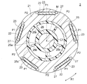
- FIG. It is sectional drawing which shows the rotor of the electric motor of Embodiment 1.
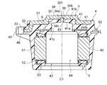
- FIG. It is sectional drawing which shows the mold stator of Embodiment 1.
- FIG. It is a top view (A) and a side view (B) which show the stator of Embodiment 1.
- FIG. It is a top view (A) and a side view (B) which show the stator, the circuit board and the substrate holding member of Embodiment 1.
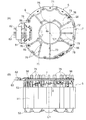
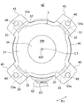
- FIG. It is a figure which looked at the mold stator of Embodiment 1 from the side of a heat dissipation member. It is a figure which looked at the mold stator of Embodiment 1 from the opening side.
- FIG. 3A is a view of the mold stator of the third embodiment as viewed from the opening side, and FIG.
- FIG. 3B is an enlarged view of a part of the mold stator.
- FIG. 6A is a view of the mold stator of the fourth embodiment as viewed from the opening side
- FIG. 3B is an enlarged view of a part of the mold stator. It is a figure which shows the arrangement of the 2nd recess of Embodiment 4. It is a figure which shows another example of the arrangement of the 2nd recess of Embodiment 4. It is sectional drawing which shows the mold stator of Embodiment 5.
- FIG. 5 is a view of the mold stator of the fifth embodiment as viewed from the heat radiating member side. It is sectional drawing which shows the mold stator of Embodiment 6.
- FIG. 1 is a partial cross-sectional view showing the electric motor 1 according to the first embodiment.
- the electric motor 1 is, for example, a brushless DC motor used in a blower of an air conditioner.
- the electric motor 1 has a rotor 2 having a rotating shaft 11 and a mold stator 4.
- the mold stator 4 includes an annular stator 5 that surrounds the rotor 2, a circuit board 6, a heat radiating member 3, and a mold resin portion 40 as a resin portion that covers them.
- the rotating shaft 11 is a rotating shaft of the rotor 2.
- the direction of the axis C1 which is the central axis of the rotating shaft 11 is referred to as "axial direction”.
- the circumferential direction (indicated by the arrow R1 in FIG. 2 and the like) about the axis C1 of the rotating shaft 11 is referred to as a “circumferential direction”.
- the radial direction centered on the axis C1 of the rotating shaft 11 is referred to as a "diameter direction”.
- the rotating shaft 11 projects from the mold stator 4 to the left side in FIG. 1, and for example, an impeller 505 of a blower (FIG. 26 (A)) is attached to the mounting portion 11a formed on the protruding portion. Therefore, the protruding side (left side in FIG. 1) of the rotating shaft 11 is referred to as "load side”, and the opposite side (right side in FIG. 1) is referred to as "counter-load side”.
- FIG. 2 is a cross-sectional view showing the rotor 2.
- the rotor 2 includes a rotating shaft 11 which is a rotating shaft, a rotor core 21 arranged radially outside the rotating shaft 11, a plurality of magnets 23 embedded in the rotor core 21, and a rotating shaft 11. It has a resin portion 25 provided between the rotor core 21 and the rotor core 21.
- the rotor core 21 is an annular member centered on the axis C1 and is provided on the outer side in the radial direction of the rotating shaft 11.
- the rotor core 21 is formed by laminating a plurality of laminated elements in the axial direction and integrally fixing them by caulking, welding, or bonding.
- the laminated element is, for example, an electromagnetic steel plate, and the plate thickness is 0.1 mm to 0.7 mm.
- the rotor core 21 has a plurality of magnet insertion holes 22.
- the magnet insertion holes 22 are arranged equidistantly in the circumferential direction and equidistant from the axis C1.
- the number of magnet insertion holes 22 is 5 here.
- the magnet insertion hole 22 extends linearly in a direction orthogonal to a linear line in the radial direction passing through the center in the circumferential direction.
- the magnet insertion hole 22 may be formed in a V shape.
- a thin-walled portion is formed between the flux barrier 27 and the outer periphery of the rotor core 21.
- the thickness of the thin portion is set to be the same as the plate thickness of the laminated element, for example, in order to suppress the leakage flux between the adjacent magnetic poles.
- the magnet 23 is composed of, for example, a rare earth magnet containing neodymium (Nd), iron (Fe) and boron (B).
- the magnet 23 is also referred to as a main magnet.
- the five magnets 23 have the same magnetic poles on the outer side in the radial direction.
- a magnetic pole opposite to the magnet 23 is formed in the region between the magnets 23 adjacent to each other in the circumferential direction.
- magnetic pole when simply referring to "magnetic pole", it is assumed that both the magnetic magnetic pole P1 and the virtual magnetic pole P2 are included.
- the number of poles of the rotor 2 is 10.
- the magnetic poles P1 and P2 of the rotor 2 are arranged at equal intervals in the circumferential direction.
- the distance between the magnet magnetic pole P1 and the virtual magnetic pole P2 is M between poles.
- the outer circumference of the rotor core 21 has a so-called flower circle shape in which the outer diameter is the largest at the pole centers of the magnetic poles P1 and P2 and the outer diameter is the smallest at the interpole M.
- the outer circumference of the rotor core 21 is not limited to the flower circle shape, but may be a circular shape.
- the number of poles of the rotor 2 is 10, but the number of poles may be an even number of 4 or more.
- one magnet 23 is arranged in one magnet insertion hole 22 here, two or more magnets 23 may be arranged in one magnet insertion hole 22.
- a non-magnetic resin portion 25 is provided between the rotating shaft 11 and the rotor core 21.
- the resin portion 25 is preferably made of a thermoplastic resin such as polybutylene terephthalate (PBT).
- PBT polybutylene terephthalate
- the resin portion 25 has a plurality of ribs that connect the annular inner cylinder portion 25a fixed to the rotating shaft 11, the annular outer cylinder portion 25c fixed to the rotor core 21, and the inner cylinder portion 25a and the outer cylinder portion 25c. It has 25b.
- the rotating shaft 11 is fixed inside the inner cylinder portion 25a of the resin portion 25.
- the ribs 25b are arranged at equal intervals in the circumferential direction, and extend radially outward from the inner cylinder portion 25a.
- a cavity 26 is formed between the ribs 25b adjacent to each other in the circumferential direction.
- the number of ribs 25b is half the number of poles, and the circumferential position of the ribs 25b coincides with the pole center of the virtual magnetic pole P2, but the number and arrangement are not limited to this.
- the sensor magnet 24 is arranged so as to face the rotor core 21 in the axial direction.
- the sensor magnet 24 is held by the resin portion 25.
- the magnetic field of the sensor magnet 24 is detected by a magnetic sensor mounted on the circuit board 6, whereby the position in the circumferential direction of the rotor 2, that is, the rotational position is detected.
- FIG. 3 is a cross-sectional view showing the mold stator 4.
- the mold stator 4 has a stator 5, a circuit board 6, a heat radiating member 3, and a mold resin portion 40.
- the stator 5 has a stator core 51, an insulating portion 52 provided on the stator core 51, and a coil 53 wound around the stator core 51 via the insulating portion 52.
- the stator core 51 is formed by laminating a plurality of laminated elements in the axial direction and integrally fixing them by caulking, welding, adhesion, or the like.
- the laminated element is, for example, an electromagnetic steel plate, and has a thickness of 0.1 mm to 0.7 mm.
- the mold resin portion 40 is formed of a thermosetting resin such as BMC (bulk molding compound).
- BMC bulk molding compound
- the mold resin portion 40 is formed so as to cover the stator 5, the circuit board 6, and the heat radiating member 3.
- the mold resin portion 40 has a bearing holding portion 41 on the counterload side and an opening 42 on the load side.
- a rotor accommodating portion 44 which is a space for accommodating the rotor 2, is formed between the bearing holding portion 41 and the opening 42.
- the rotor 2 (FIG. 1) is inserted into the rotor accommodating portion 44 through the opening 42.
- One bearing 13 that supports the rotary shaft 11 is supported by the bearing holding portion 41 of the mold resin portion 40.
- the bearing holding portion 41 will be described later.
- a metal bracket 15 (FIG. 1) is attached to the opening 42.
- the bracket 15 holds the other bearing 12 (FIG. 1) that supports the rotating shaft 11. Further, a cap 14 (FIG. 1) for preventing water or the like from entering is attached to the outside of the bracket 15.
- FIG. 4A is a plan view showing the stator 5.
- FIG. 4B is a side view showing the stator 5.
- the stator core 51 has an annular yoke 51a centered on the axis C1 and a plurality of teeth 51b extending radially inward from the yoke 51a.
- the number of teeth 51b is 12, but is not limited to this.
- the two teeth 51b are shown by broken lines.
- the coil 53 is, for example, a magnet wire, and is wound around the teeth 51b via the insulating portion 52.
- the insulating portion 52 is made of a thermoplastic resin such as PBT (polybutylene terephthalate).
- the insulating portion 52 is formed by integrally molding the thermoplastic resin with the stator core 51 or by assembling a molded body of the thermoplastic resin to the stator core 51.
- the insulating portion 52 has wall portions on the radial inner side and the radial outer side of the coil 53, respectively, and guides the coil 53 from both sides in the radial direction.
- a plurality of terminals 57 are attached to the insulating portion 52.
- the end of the coil 53 is connected to the terminal 57 by, for example, fusing (heat caulking) or soldering.
- the insulating portion 52 is also provided with a plurality of protrusions 56 for fixing the circuit board 6.
- the protrusion 56 is inserted into a mounting hole formed in the circuit board 6.
- the circuit board 6 is arranged on one side in the axial direction with respect to the stator 5, here on the counterload side.
- the circuit board 6 is a printed circuit board on which a drive circuit 61 such as a power transistor for driving the electric motor 1 is mounted, and a lead wire 63 is wired.
- the lead wire 63 of the circuit board 6 is pulled out of the electric motor 1 from the lead wire lead-out component 62 attached to the outer peripheral portion of the mold resin portion 40.
- FIG. 5A is a plan view showing a stator 5, a circuit board 6, and a board holding member 7.
- FIG. 5B is a side view showing the stator 5, the circuit board 6, and the board holding member 7.
- the circuit board 6 is arranged so that its plate surface is orthogonal to the axial direction.
- An opening 6c for securing a storage space for the bearing 13 (FIG. 1) is formed in the radial center portion of the circuit board 6.
- the lead wire lead-out component 62 described above is attached to the outer peripheral portion of the circuit board 6.
- a substrate holding member 7 as a supporting member is provided on the side opposite to the stator 5 with respect to the circuit board 6.
- the substrate pressing member 7 is provided to suppress deformation of the circuit board 6 during molding, and is made of, for example, a resin such as PBT.
- the substrate holding member 7 includes a rib 71 extending along the outer circumference of the circuit board 6, a rib 72 extending along the opening 6c of the circuit board 6, and a rib 73 connecting these ribs 71 and 72. And is formed in a skeleton shape.
- the shape of the substrate pressing member 7 is not limited to such a shape.
- the board holding member 7 has a mounting hole 76 through which the protrusion 56 of the insulating portion 52 is inserted.
- the protrusion 56 projects axially from the mounting hole 76.
- the circuit board 6 and the board holding member 7 are fixed to the stator 5 by heat welding or ultrasonic welding of the protruding tips of the protrusions 56.
- the substrate pressing member 7 has a plurality of convex portions 75 projecting to the side opposite to the stator 5.
- the convex portions 75 are formed on the ribs 71, 72, and 73, respectively, and are dispersedly arranged on the entire substrate pressing member 7.
- the convex portion 75 is a support portion that supports the heat radiating member 3.
- the bearing holding portion 41 of the mold resin portion 40 has a first surface 41a facing the rotor accommodating portion 44 and a second surface 41b on the opposite side thereof. Both the first surface 41a and the second surface 41b are planes orthogonal to the axial direction.
- the bearing holding portion 41 further has a cylindrical inner peripheral surface 41c centered on the axis C1 adjacent to the first surface 41a.
- the inner peripheral surface 41c is a cylindrical surface.
- a recess is formed by the first surface 41a and the inner peripheral surface 41c.
- the bearing 13 (FIG. 1) is housed in this recess.
- the bearing holding portion 41 is formed with a through hole 43 extending from the first surface 41a to the second surface 41b.
- the through hole 43 is formed at the radial center of the bearing holding portion 41 and extends in the axial direction.
- the cross-sectional shape of the through hole 43 on the plane orthogonal to the axial direction is, for example, circular.
- the heat radiating member 3 is provided on one side (upper side in FIG. 3) of the stator 5 in the axial direction.
- the heat radiating member 3 is made of a metal such as aluminum.
- the heat radiating member 3 has a plate-shaped portion 31 and a leg portion 32.
- the heat radiating member 3 is also referred to as a heat radiating plate.
- the plate-shaped portion 31 extends in a plane orthogonal to the axial direction, and the leg portion 32 extends radially outward from the outer circumference of the plate-shaped portion 31.
- the plate-shaped portion 31 is covered with the mold resin portion 40 in a state where the surface opposite to the stator 5 is exposed to the outside.
- the plate-shaped portion 31 has a protruding shape portion 34 at the central portion in the radial direction thereof.
- the protruding shape portion 34 has a first surface 34a in contact with the second surface 41b of the bearing holding portion 41 and a second surface 34b on the opposite side thereof.
- the protruding shape portion 34 has a cylindrical inner peripheral surface 34c centered on the axis C1 adjacent to the first surface 34a.
- the first recess 35 is formed by the first surface 34a and the inner peripheral surface 34c.
- the first recess 35 has a circular cross section on a plane orthogonal to the axial direction, and surrounds the bearing holding portion 41 of the mold resin portion 40 from the outside in the radial direction.
- a second recess 36 is formed inside the first recess 35 in the radial direction.
- the second recess 36 is a portion that engages with the positioning pin 208 (FIG. 8) of the mold 200 during molding.
- the second recess 36 is formed at the center of the first recess 35 in the radial direction, and has an inner diameter smaller than that of the first recess 35.
- the second recess 36 has a circular cross section in a plane orthogonal to the axial direction.
- the second recess 36 extends axially from the first surface 34a of the protruding shape portion 34 toward the second surface 34b. However, the second recess 36 does not reach the second surface 34b and has a bottom 301.
- FIG. 6 is a view of the mold stator 4 as viewed from the heat radiating member 3 side.
- a plurality of leg portions 32 extend radially outside the plate-shaped portion 31 in the radial direction.
- the legs 32 are formed at equal intervals about the axis C1.
- the four legs 32 are formed at 90-degree intervals about the axis C1.
- the number of legs 32 is not limited to four, and may be one or more.
- the tip portion 33 on the radial outer side of the leg portion 32 is covered with the mold resin portion 40.
- a recess 33a is formed in the tip portion 33 of the leg portion 32.
- the recess 33a is a portion that engages with the positioning pin 211 (FIG. 8) of the mold 200 during molding.
- the position of the heat radiating member 3 in the circumferential direction is determined by the inner peripheral surface of the recess 33a coming into contact with the positioning pin 211.
- the recess 33a is also used as an insertion hole for a screw that fixes the electric motor 1.
- the recess 33a has a semicircular shape that opens outward in the radial direction, but is not limited to the semicircular shape. Further, a hole may be formed instead of the recess 33a.
- the surface side (including the protruding shape portion 34) of the plate-shaped portion 31 of the heat radiating member 3 is exposed to the outside from the mold resin portion 40, it is also referred to as an exposed portion.
- a portion of the heat radiating member 3 other than the exposed portion, for example, the stator 5 side (including the leg portion 32) of the plate-shaped portion 31 is covered with the mold resin portion 40, and is therefore also referred to as a buried portion.
- the mold resin portion 40 has mounting legs 45 at positions corresponding to the legs 32 of the heat radiating member 3.
- the four mounting legs 45 are formed at 90-degree intervals about the axis C1.
- the number of mounting legs 45 is not limited to four, and may be one or more.
- a hole 46 is formed in the mounting leg 45.
- the hole portion 46 is formed at a position where it overlaps with the recess 33a of the heat radiating member 3 in the axial direction.
- the hole portion 46 is formed by preventing the resin from flowing into the portion of the mold 200 where the positioning pin 211 (FIG. 8) exists during molding.
- the hole 46 is also used as an insertion hole for a screw that fixes the electric motor 1.
- the hole portion 46 has a circular shape here, but is not limited to the circular shape. Further, a recess may be formed instead of the hole 46.
- FIG. 7 is a view of the mold stator 4 configured in this way as viewed from the opening 42 side.
- the through hole 43 of the bearing holding portion 41 and the second recess 36 of the heat radiating member 3 can be seen at the radial center of the rotor accommodating portion 44.
- FIG. 8 is a cross-sectional view showing a mold 200 used in the manufacturing process of the electric motor 1.
- the mold 200 includes an upper mold 201 and a lower mold 202 that can be opened and closed, and a cavity 204 is formed between the upper mold 201 and the lower mold 202.
- the upper mold 201 is formed with a heat radiating member accommodating portion 203 for accommodating the heat radiating member 3.
- the lower mold 202 has a core 205 protruding into the cavity 204.
- the core 205 extends axially from the bottom of the cavity 204.
- the core 205 has a first core 206 corresponding to the rotor accommodating portion 44 of the mold resin portion 40 and a second core 207 corresponding to the recess of the bearing holding portion 41.
- a positioning pin 208 as a positioning member is formed at the upper end of the second core portion 207.
- the positioning pin 208 is formed at the radial center of the core 205 and projects axially from the upper end of the second core portion 207.
- the positioning pin 208 engages with the second recess 36 (FIG. 3) of the heat radiating member 3 to position the heat radiating member 3 in the axial and radial directions.
- a large diameter portion 209 protruding outward in the radial direction from the core 205 is formed.
- the large diameter portion 209 is a portion corresponding to the opening 42 (FIG. 3) of the mold stator 4.
- the lower mold 202 is also formed with a gate 210, which is a flow path for injecting resin into the cavity 204.
- a positioning pin 211 extending in the axial direction is formed on the outer peripheral portion of the cavity 204. The positioning pin 211 engages with the recess 33a (FIG. 6) of the heat radiating member 3 to position the heat radiating member 3 in the circumferential direction.
- FIG. 9 is a flowchart showing the manufacturing process of the electric motor 1.
- 10 (A), (B) and 11 are schematic views for each process showing the manufacturing process of the electric motor 1.
- the stator core 51 is formed by laminating a plurality of laminated elements in the axial direction and fixing them integrally by caulking or the like (step S101).
- the insulating portion 52 is attached to the stator core 51 or integrally molded (step S102).
- the coil 53 is wound around the stator core 51 via the insulating portion 52 (step S103). As a result, the stator 5 is formed.
- step S104 the upper mold 201 of the mold 200 is moved upward to open the cavity 204, and the stator 5 is installed in the cavity 204 (step S104). As shown in FIG. 10A, the stator 5 is mounted around the core 205 of the mold 200.
- step S105 the circuit board 6 and the board holding member 7 are mounted on the stator 5 (step S105).
- the protrusion 56 (FIG. 5 (B)) of the insulating portion 52 of the stator 5 is inserted into the mounting hole of the circuit board 6 and the mounting hole 76 (FIG. 5 (A)) of the substrate holding member 7, and the protrusion 56 is formed.
- the circuit board 6 and the board holding member 7 are fixed to the stator 5 by heat welding or the like at the tip.
- the substrate pressing member 7 is omitted in FIGS. 10A to 11.
- the heat radiating member 3 is mounted on the stator 5 in the mold 200 (S106). At this time, as shown in FIG. 10B, the positioning pin 208 of the core 205 is engaged with the second recess 36 of the heat radiating member 3. As a result, the heat radiating member 3 is positioned axially and radially with respect to the mold 200.
- the positioning pin 211 (FIG. 11) of the mold 200 is engaged with the recess 33a (FIG. 11) of the tip portion 33 of the heat radiating member 3.
- the heat radiating member 3 is positioned in the circumferential direction with respect to the mold 200.
- the upper mold 201 is moved downward to close the cavity 204, and molding is performed (step S107). That is, the molten mold resin is injected from the gate 210 into the cavity 204.
- the mold resin injected into the cavity 204 covers the stator 5, the circuit board 6, and the substrate holding member 7, and further covers a part of the heat radiating member 3.
- the mold resin in the cavity 204 is cured by injecting the mold resin into the cavity 204 and then heating the mold 200.
- the mold resin portion 40 is formed. That is, the mold stator 4 is formed by covering the stator 5, the circuit board 6, and the substrate holding member 7 with the mold resin portion 40.
- a through hole 43 is formed in the bearing holding portion 41.
- the through hole 43 of the bearing holding portion 41 is formed at a position where it vertically overlaps with the second recess 36 of the heat radiating member 3.
- the hole portion 46 is formed in the mounting leg 45.
- the hole 46 of the mounting leg 45 is formed at a position where it vertically overlaps the recess 33a of the heat radiating member 3.
- a rotor 2 is formed separately from steps S101 to S107. That is, a plurality of laminated elements are laminated in the axial direction and fixed integrally by caulking or the like to form the rotor core 21, and the magnet 23 is inserted into the magnet insertion hole 22. Further, the rotating shaft 11, the rotor core 21, the magnet 23, and the sensor magnet 24 are integrally molded with the resin to be the resin portion 25. As a result, the rotor 2 is formed.
- the bearings 12 and 13 are attached to the rotating shaft 11 of the rotor 2 and inserted into the rotor accommodating portion 44 through the opening 42 of the mold stator 4 (step S108). Further, the bracket 15 is attached to the opening 42 of the mold stator 4, and the cap 14 is attached to the outside of the bracket 15. As a result, the electric motor 1 is completed.
- the heat radiating member 3 efficiently releases the heat generated in the drive circuit 61 and the coil 53 of the circuit board 6 to the outside of the electric motor 1 to suppress the temperature rise of the electric motor 1. Since a part of the heat radiating member 3 is covered by the mold resin portion 40, the contact thermal resistance between the mold resin portion 40 and the heat radiating member 3 is reduced as compared with the case where the heat radiating member 3 is attached to the mold stator 4 from the outside. It is possible to improve heat dissipation.
- the heat radiating member 3 since the heat radiating member 3 has the second recess 36 inside the first recess 35 in the radial direction, the heat radiating member 3 is formed by engaging the positioning pin 208 of the mold 200 with the second recess 36. It can be positioned with respect to the radial center of the mold 200. As a result, the stator 5 and the heat radiating member 3 can be positioned with high accuracy. As a result, vibration and noise caused by the misalignment between the stator 5 and the heat radiating member 3 can be suppressed.
- the mold resin portion 40 is provided so as to cover a part of the heat radiating member 3, the resin also enters the unevenness of the surface of the heat radiating member 3. Therefore, the hollow portion between the mold resin portion 40 and the heat radiating member 3 can be reduced, and the heat radiating property can be improved.
- the surface side (including the protruding shape portion 34) of the heat radiating member 3 is exposed to the outside from the mold resin portion 40, heat is effectively released to the outside of the mold stator 4, and the heat radiating effect can be further enhanced. ..
- the heat radiating member 3 is molded with resin together with the stator 5, steps such as screwing and press-fitting for fixing the heat radiating member 3 are not required, and the number of steps can be reduced.
- the heat radiating member 3 is exposed to the rotor accommodating portion 44 from the through hole 43 of the bearing holding portion 41, but since the rotor 2 is accommodated in the rotor accommodating portion 44, the heat radiating member 3 comes into contact with water or the like. Aged deterioration is prevented.
- the electric motor 1 of the first embodiment is arranged on one side in the axial direction of the rotor 2 having the rotating shaft 11 and the bearings 12 and 13, the stator 5 surrounding the rotor 2, and the rotor 2.
- a heat-dissipating member 3 and a mold resin portion 40 that covers at least a part of the heat-dissipating member 3 and the stator 5 are provided. Therefore, the heat generated by the electric motor 1 can be efficiently released from the heat radiating member 3 to the outside, and the temperature rise of the electric motor 1 can be suppressed.
- the heat radiating member 3 has a first recess 35 that surrounds the bearing 13 from the outside in the radial direction, and a second recess 36 that is formed inside the first recess 35 in the radial direction. Therefore, by engaging the positioning pin 208 of the mold 200 with the second recess 36 of the heat radiating member 3, the heat radiating member 3 can be positioned with respect to the mold 200 with high accuracy. As a result, the positional accuracy of the heat radiating member 3 with respect to the stator 5 can be improved, and vibration and noise can be suppressed.
- first recess 35 is formed so as to surround the bearing holding portion 41 from the outside in the radial direction, a storage space for the bearing holding portion 41 for holding the bearing 13 is secured, and the mold stator 4 is compactly configured. be able to.
- the heat radiating member 3 can be positioned with high accuracy with respect to the radial center of the mold 200.
- the positioning pin 208 of the mold 200 that engages with the second recess 36 can have a simple shape. As a result, the manufacturing cost can be reduced.
- the heat radiating member 3 since a part of the heat radiating member 3 is exposed from the mold resin portion 40 and the other part is covered with the mold resin portion 40, the heat generated by the stator 5 and the like is efficiently transferred to the heat radiating member 3, and the heat radiating member 3 It is possible to efficiently dissipate heat to the outside.
- the circuit board 6 is provided between the stator 5 and the heat radiating member 3, the heat generated by the circuit board 6 can be efficiently radiated from the heat radiating member 3 to the outside.
- the rotor 2 is a concave pole type and the number of magnets 23 is half that of the non-consequent pole type rotor 2A (see FIG. 25), the size of the magnet 23 made of a high magnetic force rare earth magnet Can be increased. As a result, the magnetic force of the magnet 23 can be increased and the processing cost can be reduced. That is, it is possible to realize high output and miniaturization of the electric motor 1 while reducing the manufacturing cost.
- the output of the motor 1 is increased and the size is reduced, the output density is increased, so that the amount of heat generated by the motor 1 is increased.
- heat can be efficiently radiated to the outside through the heat radiating member 3, so that high output and miniaturization can be realized while suppressing a temperature rise of the electric motor 1.
- the magnetic attraction force acting between the stator 5 and the teeth 51b tends to be large at the magnet magnetic pole P1 and small at the virtual magnetic pole P2. Therefore, a radial excitation force acts on the rotor 2 during rotation, and vibration and noise are likely to be generated.
- the heat radiating member 3 is positioned with high accuracy with respect to the stator 5 as described above, it is possible to suppress an increase in vibration and noise.
- FIG. 12 is a cross-sectional view showing the mold stator 4A of the second embodiment.
- the mold stator 4A of the second embodiment is different from the first embodiment in the shapes of the second recess 36A of the heat radiating member 3 and the through hole 43A of the bearing holding portion 41.
- the second recess 36 of the heat radiating member 3 and the through hole 43 of the bearing holding portion 41 are both cylindrical.
- the inner peripheral surfaces of the second recess 36A of the heat radiating member 3 and the through hole 43A of the bearing holding portion 41 in the second embodiment are both inclined in the axial direction.
- FIG. 13 is an enlarged cross-sectional view showing the second recess 36A of the heat radiating member 3 and the through hole 43A of the bearing holding portion 41.
- the second recess 36A of the heat radiating member 3 extends from the first surface 34a of the protruding shape portion 34 toward the second surface 34b, but does not reach the second surface 34b and is the bottom portion. It has 301.
- the inner peripheral surface of the second recess 36A is inclined so that the inner diameter D1 on the first surface 34a is larger than the inner diameter D2 on the bottom 301.
- the inner peripheral surface of the second recess 36A is such that the inner diameter D1 at the end closer to the rotor housing 44 is larger than the inner diameter D2 at the end far from the rotor housing 44. Is sloping. That is, the inner peripheral surface of the second recess 36A is inclined so that the cross-sectional area becomes smaller as the distance from the rotor accommodating portion 44 in the axial direction increases.
- the inner peripheral surface of the through hole 43A is inclined so that the inner diameter D0 on the first surface 41a is larger than the inner diameter D1 on the second surface 41b.
- the inner peripheral surface of the through hole 43A is inclined so that the cross-sectional area becomes smaller as the distance from the rotor accommodating portion 44 in the axial direction increases.
- the positioning pin 208 (FIG. 8) of the mold 200 is provided with the same inclination as the second recess 36A. This facilitates the engagement between the second recess 36A and the positioning pin 208.
- the alignment function is obtained by the contact between the second recess 36A and the positioning pin 208, whereby the coaxiality between the heat radiating member 3 and the stator 5 can be improved.
- the through hole 43A is formed by preventing the resin from flowing into the portion corresponding to the positioning pin 208 (FIG. 8) of the mold 200, the inner peripheral surface of the through hole 43A is the inner circumference of the second recess 36A. Has an inclination of the same angle as the surface. As a result, the through hole 43A and the positioning pin 208 have a draft, and the releasability when the mold stator 4A is taken out from the mold 200 is improved.
- the electric motor of the second embodiment is configured in the same manner as the electric motor 1 of the first embodiment except for the above-mentioned points.
- the second recess 36A is inclined with respect to the axial direction, the second recess 36 is engaged with the positioning pin 208 of the mold 200. Becomes easier. Therefore, the heat radiating member 3 can be easily installed in the mold 200, and the manufacturing process can be simplified.
- the second recess 36A has an inclination such that the inner diameter D1 on the first surface 34a is larger than the inner diameter D2 on the bottom 301, the through hole 43A and the positioning pin 208 have a draft. , The mold releasability when the mold stator 4A is taken out from the mold 200 is improved. In addition, since the centering function is obtained by the contact between the second recess 36A and the positioning pin 208, the coaxiality between the heat radiating member 3 and the stator 5 can be improved.
- FIG. 14 is a cross-sectional view showing a mold stator 4B of a modified example of the second embodiment.
- the second recess 36A had a flat bottom 301.
- the second recess 36B has a point-shaped bottom 302. That is, the second recess 36B has a conical shape.
- the shape of the through hole 43B is the same as that of the through hole 43A of the second embodiment.
- FIG. 15A is a view of the mold stator 4C of the third embodiment as viewed from the opening 42 side.
- the mold stator 4C of the third embodiment is different from the first embodiment in the shapes of the second recess 36C of the heat radiating member 3 and the through hole 43C of the bearing holding portion 41.
- the second recess 36 of the heat radiating member 3 has a circular cross section.
- the second recess 36C of the heat radiating member 3 of the third embodiment has a polygonal cross section, for example, a quadrangular cross section.
- the cross-sectional shape of the second recess 36C is not limited to a quadrangle, but may be a quadrangle or a pentagon or more.
- the through hole 43C of the bearing holding portion 41 has a polygonal cross section similar to that of the second recess 36C.
- the through hole 43C of the bearing holding portion 41 is formed by preventing the resin from flowing into the portion of the mold 200 where the positioning pin 208 (FIG. 8) exists.
- the positioning pin 208 (FIG. 8) of the mold 200 has a polygonal shape similar to that of the second recess 36C.
- the engagement of the second recess 36C, which is polygonal in shape, with the positioning pin 208 prevents the heat radiating member 3 from rotating in the mold 200.
- FIG. 15B is an enlarged cross-sectional view showing the second recess 36C of the heat radiating member 3 and the through hole 43C of the bearing holding portion 41.
- the second recess 36C of the heat radiating member 3 extends from the first surface 34a of the protruding shape portion 34 toward the second surface 34b and has a bottom portion 301.
- the through hole 43C of the bearing holding portion 41 reaches from the first surface 41a to the second surface 41b.
- the second recess 36C has a constant cross-sectional area in the axial direction here, but has an inclination such that the cross-sectional area becomes smaller as the distance from the rotor accommodating portion 44 in the axial direction increases, as described in the second embodiment. You may be doing it. Further, the second recess 36C may have a point-shaped bottom as shown in FIG.
- the through hole 43C has a constant cross-sectional area in the axial direction here, but as described in the second embodiment, the through hole 43C is inclined so that the cross-sectional area becomes smaller as the distance from the rotor accommodating portion 44 in the axial direction increases. You may have.
- the electric motor of the third embodiment is configured in the same manner as the electric motor 1 of the first embodiment except for the above-mentioned points.
- the polygonal positioning pin 208 of the mold 200 is engaged with the second recess 36C. , It is possible to prevent the heat radiating member 3 from rotating in the mold 200.
- FIG. 16A is a view of the mold stator 4D of the fourth embodiment as viewed from the opening 42 side.
- the mold stator 4D of the fourth embodiment differs from the first embodiment in the number of the second recess 36D of the heat radiating member 3 and the through holes 43D of the bearing holding portion 41.
- the heat radiating member 3 has a single second recess 36.
- the heat radiating member 3 has a plurality of second recesses 36D.
- the number of the second recesses 36D is 4 here, but it may be 2 or more.
- the number of through holes 43D of the bearing holding portion 41 is formed in the same number as the number of the second recesses 36D. Each through hole 43D is formed at a position where it vertically overlaps with the second recess 36D.
- the second recess 36D and the through hole 43D have a circular cross section here, but may have a polygonal cross section as described in the third embodiment.
- FIG. 16B is an enlarged cross-sectional view showing the second recess 36D of the heat radiating member 3 and the through hole 43D of the bearing holding portion 41.
- the second recess 36D of the heat radiating member 3 extends from the first surface 34a of the protruding shape portion 34 toward the second surface 34b and has a bottom portion 301.
- the through hole 43D of the bearing holding portion 41 reaches from the first surface 41a to the second surface 41b.
- the second recess 36D has a constant cross-sectional area in the axial direction here, but as described in the second embodiment, has an inclination such that the cross-sectional area becomes smaller as the distance from the rotor accommodating portion 44 in the axial direction increases. You may be doing it. Further, the second recess 36D may have a point-shaped bottom as shown in FIG.
- the through hole 43D has a constant cross-sectional area in the axial direction here, but as described in the second embodiment, the through hole 43D is inclined so that the cross-sectional area becomes smaller as the distance from the rotor accommodating portion 44 in the axial direction increases. You may have.
- FIG. 17 is a diagram showing the arrangement of the four second recesses 36D.
- the four second recesses 36D are arranged equidistantly in the radial direction from the axis C1 and equidistant in the circumferential direction about the axis C1, here at 90 degree intervals.
- the arrangement of the through hole 43D is the same as the arrangement of the second recess 36D.
- the positioning pins 208 (FIG. 8) of the mold 200 are provided corresponding to two or more of the second recesses 36D of the heat radiating member 3. Since the second recess 36 of the heat radiating member 3 is arranged equidistantly from the axis C1 and at equal intervals in the circumferential direction, the positioning pin 208 can be moved even if the positions of the heat radiating member 3 in the circumferential direction are changed in a plurality of ways. It can be engaged with the recess 36D of 2.
- FIG. 18 is a diagram showing an arrangement when the number of the second recesses 36D is two.
- the two second recesses 36D are arranged equidistantly in the radial direction from the axis C1 and equidistant in the circumferential direction about the axis C1, here at 180 degree intervals.
- the arrangement of the through hole 43D is the same as the arrangement of the second recess 36D.
- the electric motor of the fourth embodiment is configured in the same manner as the electric motor 1 of the first embodiment except for the above-mentioned points.
- the positioning pin 208 of the mold 200 is engaged with the second recess 36D in the mold 200. It is possible to prevent the heat radiating member 3 from rotating.
- the positioning pin 208 even if the circumferential position of the heat radiating member 3 is changed in a plurality of ways. Can be engaged with the second recess 36D. Further, the weight balance of the electric motor 1 can be improved.
- FIG. 19 is a cross-sectional view showing the mold stator 4E of the fifth embodiment.
- the shape of the second recess 36E of the heat radiating member 3 is different from that of the first embodiment.
- the second recess 36E of the first embodiment described above extends from the first surface 34a of the protruding shape portion 34 toward the second surface 34b, but does not reach the second surface 34b. It was. On the other hand, the second recess 36E of the fifth embodiment reaches from the first surface 34a to the second surface 34b of the protruding shape portion 34.
- FIG. 20 is a view of the mold stator 4 as viewed from the heat radiating member 3 side. Since the second recess 36E reaches the second surface 34b of the protruding shape portion 34, when the mold stator 4 is viewed from the heat radiating member 3 side, the second recess 36E is formed on the second surface 34b of the protruding shape portion 34. Is appearing.
- the second recess 36E has a circular cross section here, and the cross-sectional shape is constant in the axial direction.
- the second recess 36E may have an inclination as described in the second embodiment, or may have a polygonal cross section as described in the third embodiment.
- a plurality of second recesses 36E may be provided.
- the electric motor of the fifth embodiment has the same configuration as the electric motor 1 of the first embodiment except for the above-mentioned points.
- the second recess 36E is formed so as to reach the second surface 34b of the heat radiating member 3, when the heat radiating member 3 is installed in the mold 200, the second recess 36E The positioning pin 208 can be seen through. Therefore, workability is improved.
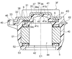
- FIG. 21 is a cross-sectional view showing the mold stator 4F of the sixth embodiment.
- the shape of the heat radiating member 3F of the mold stator 4F of the sixth embodiment is different from that of the first embodiment.
- the heat radiating member 3 of the first embodiment had a plate-shaped portion 31 and a leg portion 32.
- the heat radiating member 3F of the sixth embodiment has fins 37 in addition to the plate-shaped portion 31 and the leg portion 32.
- the fin 37 is formed on the side of the plate-shaped portion 31 opposite to the rotor accommodating portion 44.
- the fins 37 project outward from the mold resin portion 40.
- the heat radiating member 3F having such fins 37 is also referred to as a heat sink.
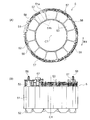
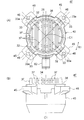
- FIG. 22A is a view of the mold stator 4F as viewed from the heat dissipation member 3F side.
- FIG. 22B is a side view showing the mold stator 4F.
- a plurality of fins 37 are arranged in one direction (left-right direction in FIG. 22A) in a plane orthogonal to the axial direction. Each fin 37 has a long shape in a direction orthogonal to the arrangement direction.
- a flange portion 38 that surrounds the fin 37 from the outside in the radial direction is formed on the surface of the plate-shaped portion 31 of the heat radiating member 3F.
- the flange portion 38, together with the fins 37, is exposed from the mold resin portion 40.
- the fin 37 and the flange portion 38 form a part of the exposed portion exposed from the mold resin portion 40.
- the plate-shaped portion 31 of the heat radiating member 3F and the bearing holding portion 41 of the mold resin portion 40 are formed with the second recess 36 and the through hole 43 described in the first embodiment.
- the second recess 36 and the through hole 43 may have the shapes described in the second to fifth embodiments.
- the electric motor of the sixth embodiment is configured in the same manner as the electric motor 1 of the first embodiment except for the above-mentioned points.
- the heat radiating member 3F has fins 37 and the fins 37 are exposed to the outside from the mold resin portion 40, the heat generated by the stator 5 and the like is efficiently radiated from the fins 37 to the outside. can do. As a result, the heat dissipation of the electric motor 1 can be further improved.
- FIG. 23 is a cross-sectional view showing the mold stator 4G of the seventh embodiment.
- the heat radiating sheet 9 is arranged between the heat radiating member 3F and the circuit board 6.
- the heat radiating sheet 9 is made of a resin having a higher thermal conductivity than the molded resin portion 40, for example, a silicone resin.
- the heat radiating sheet 9 is arranged between the plate-shaped portion 31 of the heat radiating member 3F and the circuit board 6.
- the substrate holding member 7 (FIG. 5A) described in the first embodiment may be arranged between the heat radiating member 3F and the circuit board 6. Since the substrate pressing member 7 has a skeleton shape in which a plurality of ribs are combined, the heat radiating sheet 9 can be arranged between the heat radiating member 3F and the circuit board 6 by utilizing the space between the ribs.
- FIG. 24 is an enlarged cross-sectional view showing a portion including the heat radiating member 3F, the heat radiating sheet 9, and the circuit board 6.
- the circuit board 6 has a first plate surface 6a on the stator 5 side and a second plate surface 6b opposite to the first plate surface 6a.
- An element 65 such as a drive circuit 61 is mounted on the first plate surface 6a of the circuit board 6 by soldering.
- the heat radiating sheet 9 has a first sheet surface 9a on the stator 5 side and a second sheet surface 9b which is the opposite surface thereof.
- the first sheet surface 9a is in contact with the second plate surface 6b of the circuit board 6.
- the second seat surface 9b is in contact with the plate-shaped portion 31 of the heat radiating member 3F.
- a through hole 66 extending from the first plate surface 6a to the second plate surface 6b is formed at a position corresponding to the soldered portion of the element 65 of the circuit board 6.
- a heat conductive member 68 such as copper is arranged inside the through hole 66. That is, the heat conductive member 68 is in contact with both the element 65 and the heat radiating sheet 9.
- the heat radiating sheet 9 is attached to the heat radiating member 3F, installed on the mold 200 (FIG. 8) together with the stator 5, the circuit board 6, and the board holding member 7, and molded.
- the heat radiating sheet 9 is arranged between the heat radiating member 3F and the circuit board 6 can be obtained.
- the heat radiating sheet 9 By arranging the heat radiating sheet 9 between the heat radiating member 3F and the circuit board 6, the heat generated in the circuit board 6 is easily transferred to the heat radiating member 3F via the heat radiating sheet 9, and the heat radiating property is further improved. Can be done.
- the heat radiating sheet 9 is sandwiched between the heat radiating member 3F and the circuit board 6 and compressed to some extent. In this way, the resin does not enter between the heat radiating sheet 9 and the heat radiating member 3F and between the heat radiating sheet 9 and the circuit board 6 during molding, so that the heat radiating sheet 9, the heat radiating member 3F and the circuit board 6 do not enter. High adhesion with and can be obtained.
- the heat radiating sheet 9 is molded together with the heat radiating member 3F and the circuit board 6, the adhesiveness of the heat radiating sheet 9 may be small. Therefore, the range of selection of the material of the heat radiating sheet 9 is widened.
- the heat generated by the element 65 on the first plate surface 6a of the circuit board 6 is transferred to the heat radiating sheet 9 via the heat conductive member 68 in contact with the soldered portion of the element 65 and the heat radiating sheet 9. Therefore, the heat generated by the element 65 can be transferred from the heat radiating sheet 9 to the heat radiating member 3F and efficiently discharged from the fins 37 to the outside. Thereby, heat dissipation can be improved.
- the heat radiating member 3F the heat radiating member 3 of the first to fifth embodiments may be used.
- the element on the circuit board 6 comes into contact with the heat radiating sheet 9, and the heat radiating sheet 9 becomes uneven.
- the adhesion to the circuit board 6 may be locally reduced.
- the electric motor 1 of the seventh embodiment has the same configuration as the electric motor 1 of the first embodiment except for the above-mentioned points.
- the electric motor of the seventh embodiment includes the heat radiating sheet 9 between the heat radiating member 3F and the circuit board 6, the heat generated by the circuit board 6 is transferred to the heat radiating member 3F via the heat radiating sheet 9. It becomes easier and the heat dissipation can be further improved.
- the circuit board 6 has the element 65 on the first plate surface 6a, the second plate surface 6b is in contact with the heat radiating sheet 9, and the element 65 and the heat radiating sheet 9 are connected by the heat conductive member 68.
- the adhesion between the circuit board 6 and the heat radiating sheet 9 can be improved, and the heat of the element 65 can be efficiently transferred to the heat radiating sheet 9.
- FIG. 25 is a cross-sectional view showing the rotor 2A of the modified example.
- the rotor 2 (FIG. 2) of each of the above-described embodiments was a sequential pole type having a magnet magnetic pole and a virtual magnetic pole.
- the rotor 2A of the modified example is a non-consequential pole type in which all magnetic poles are composed of magnetic magnetic poles.
- the rotor 2A has a cylindrical rotor core 21 centered on the axis C1.
- the rotor core 21 is formed by laminating a plurality of electromagnetic steel plates in the axial direction and fixing them by caulking, welding, or bonding.
- the thickness of the electromagnetic steel sheet is, for example, 0.1 mm to 0.7 mm.
- the rotor core 21 has a central hole in the radial center, and the rotating shaft 11 is fixed to the central hole.
- a plurality of magnet insertion holes 22 are arranged at equal intervals in the circumferential direction in the rotor core 21.
- the shape of each magnet insertion hole 22 is as described in the first embodiment.
- Flux barriers 27 are formed on both sides of the magnet insertion hole 22 in the circumferential direction.
- the number of magnet insertion holes 22 is 10 here, but is not limited to 10.
- a magnet 23 is inserted into each magnet insertion hole 22.
- the material and shape of the magnet 23 are as described in the first embodiment.
- the magnets 23 adjacent to each other in the circumferential direction are arranged so that the magnetic poles opposite to each other face the outer peripheral side of the rotor core 21. Therefore, all the magnetic poles of the rotor 2A are formed by the magnet 23.
- the number of magnetic poles of the rotor 2A is 10 poles.
- the non-sequential pole type rotor 2A is less likely to generate vibration and noise than the consequential pole type rotor 2. Even when the non-consequential pole type rotor 2A is used as in this modification, the effects described in the first to seventh embodiments can be achieved.
- FIG. 26A is a diagram showing a configuration of an air conditioner 500 to which the electric motor 1 of the first embodiment is applied.
- the air conditioner 500 includes an outdoor unit 501, an indoor unit 502, and a refrigerant pipe 503 connecting them.
- the outdoor unit 501 includes, for example, an outdoor blower 510 that is a propeller fan
- the indoor unit 502 includes, for example, an indoor blower 520 that is a cross-flow fan.
- the outdoor blower 510 has an impeller 505 and an electric motor 1A for driving the impeller 505.
- the indoor blower 520 has an impeller 521 and an electric motor 1B for driving the impeller 521. Both the electric motors 1A and 1B are composed of the electric motor 1 described in the first embodiment.
- FIG. 26A also shows a compressor 504 that compresses the refrigerant.
- FIG. 26B is a cross-sectional view of the outdoor unit 501.
- the electric motor 1A is supported by a frame 509 arranged in the housing 508 of the outdoor unit 501.
- An impeller 505 is attached to the rotating shaft 11 of the electric motor 1 via a hub 506.
- the impeller 505 is rotated by the rotation of the rotor 2 of the electric motor 1A to blow air to the outside.
- heat is released when the refrigerant compressed by the compressor 504 is condensed by the condenser, and this heat is released to the outside by the blower of the outdoor blower 510.
- the impeller 521 is rotated by the rotation of the rotor 2 of the electric motor 1B to blow air into the room.
- the heat of the air is taken when the refrigerant evaporates in the evaporator, and the air is blown into the room by the blower of the indoor blower 520.
- the electric motor 1 of the first embodiment described above has high heat dissipation and low cost. Therefore, by configuring the electric motors 1A and 1B with the electric motor 1 of the first embodiment, the reliability of the air conditioner 500 can be improved and the manufacturing cost can be reduced.
- any of the electric motors 2 to 7 of the embodiments may be used as the electric motors 1A and 1B.
- the electric motor 1 is used for the electric motor 1A of the outdoor blower 510 and the electric motor 1B of the indoor blower 520, but the electric motor 1 may be used as at least one of the drive sources.
- the electric motor 1 described in each embodiment can be mounted on an electric device other than the blower of the air conditioner.
Landscapes
- Engineering & Computer Science (AREA)
- Power Engineering (AREA)
- Manufacturing & Machinery (AREA)
- Mechanical Engineering (AREA)
- Chemical & Material Sciences (AREA)
- Combustion & Propulsion (AREA)
- Microelectronics & Electronic Packaging (AREA)
- General Engineering & Computer Science (AREA)
- Motor Or Generator Cooling System (AREA)
- Manufacture Of Motors, Generators (AREA)
- Motor Or Generator Frames (AREA)
- Iron Core Of Rotating Electric Machines (AREA)
- Permanent Field Magnets Of Synchronous Machinery (AREA)
Abstract
電動機は、回転シャフトと、回転シャフトに取り付けられた軸受とを有するロータと、ロータを囲むステータと、回転シャフトの軸方向において、ロータの一方の側に配置された放熱部材と、放熱部材の少なくとも一部とステータとを覆う樹脂部とを備える。放熱部材は、軸受を、回転シャフトを中心とする径方向の外側から囲む第1の凹部と、第1の凹部の径方向の内側に形成された第2の凹部と有する。
Description
本発明は、電動機、送風機、空気調和装置および電動機の製造方法に関する。
電動機は、熱を外部に放出するため、ヒートシンク等の放熱部材を備える。放熱部材は、圧入またはネジ止め等により、電動機のステータに固定される(例えば、特許文献1参照)。
しかしながら、従来の構成では、電動機と放熱部材との間の接触熱抵抗のため、放熱性の向上に限界がある。また、接触熱抵抗を低減するために放熱部材とステータとを樹脂で一体成形する場合、金型内での放熱部材の位置決めが難しい。金型内での放熱部材の位置精度が低いと、ステータに対する放熱部材の位置精度が低くなる。ステータと放熱部材との位置ずれは、電動機の振動および騒音の原因となる。
本発明は、上記の課題を解決するためになされたものであり、電動機の放熱性を向上し、且つステータに対する放熱部材の位置精度を向上することを目的とする。
本発明の一態様による電動機は、回転シャフトと、回転シャフトに取り付けられた軸受とを有するロータと、ロータを囲むステータと、回転シャフトの軸方向において、ロータの一方の側に配置された放熱部材と、放熱部材の少なくとも一部とステータとを覆う樹脂部とを備える。放熱部材は、軸受を、回転シャフトを中心とする径方向の外側から囲む第1の凹部と、第1の凹部の径方向の内側に形成された第2の凹部と有する。
本発明によれば、ステータで発生した熱が樹脂部および放熱部材を介して放出されるため、放熱性を向上することができる。また、第2の凹部に金型の位置決め部を係合させることで、金型内での放熱部材の位置精度を向上することができる。これにより、ステータに対する放熱部材の位置精度を向上することができ、電動機の振動および騒音を抑制することができる。
以下、本発明の実施の形態について、図面を参照して詳細に説明する。なお、この実施の形態により本発明が限定されるものではない。
実施の形態1.
<電動機1の構成>
図1は、実施の形態1における電動機1を示す部分断面図である。電動機1は、例えば空気調和装置の送風機に用いられるブラシレスDCモータである。
<電動機1の構成>
図1は、実施の形態1における電動機1を示す部分断面図である。電動機1は、例えば空気調和装置の送風機に用いられるブラシレスDCモータである。
電動機1は、回転シャフト11を有するロータ2と、モールドステータ4とを有する。モールドステータ4は、ロータ2を囲む環状のステータ5と、回路基板6と、放熱部材3と、これらを覆う樹脂部としてのモールド樹脂部40とを有する。回転シャフト11は、ロータ2の回転軸である。
以下の説明では、回転シャフト11の中心軸線である軸線C1の方向を、「軸方向」と称する。また、回転シャフト11の軸線C1を中心とする周方向(図2等に矢印R1で示す)を、「周方向」と称する。回転シャフト11の軸線C1を中心とする半径方向を、「径方向」と称する。
回転シャフト11は、モールドステータ4から図1における左側に突出しており、その突出部に形成された取付け部11aには、例えば送風機の羽根車505(図26(A))が取り付けられる。そのため、回転シャフト11の突出側(図1における左側)を「負荷側」と称し、反対側(図1における右側)を「反負荷側」と称する。
<ロータ2の構成>
図2は、ロータ2を示す断面図である。図2に示すように、ロータ2は、回転軸である回転シャフト11と、回転シャフト11の径方向外側に配置されたロータコア21と、ロータコア21に埋め込まれた複数のマグネット23と、回転シャフト11とロータコア21との間に設けられた樹脂部25とを有する。
図2は、ロータ2を示す断面図である。図2に示すように、ロータ2は、回転軸である回転シャフト11と、回転シャフト11の径方向外側に配置されたロータコア21と、ロータコア21に埋め込まれた複数のマグネット23と、回転シャフト11とロータコア21との間に設けられた樹脂部25とを有する。
ロータコア21は、軸線C1を中心とする環状の部材であり、回転シャフト11の径方向外側に設けられている。ロータコア21は、複数の積層要素を軸方向に積層し、カシメ、溶接または接着によって一体に固定したものである。積層要素は、例えば電磁鋼板であり、板厚は0.1mm~0.7mmである。
ロータコア21は、複数の磁石挿入孔22を有する。磁石挿入孔22は、周方向に等間隔で、且つ軸線C1から等距離に配置されている。磁石挿入孔22の数は、ここでは5である。磁石挿入孔22は、その周方向中心を通る径方向の直線に直交する方向に、直線状に延在している。なお、磁石挿入孔22は、V字状に形成されていてもよい。
磁石挿入孔22の周方向両側には、空隙部であるフラックスバリア27が形成されている。フラックスバリア27とロータコア21の外周との間には、薄肉部が形成されている。薄肉部の厚さは、隣り合う磁極間の漏れ磁束を抑制するため、例えば、積層要素の板厚と同等に設定されている。
各磁石挿入孔22には、永久磁石であるマグネット23が挿入されている。マグネット23は、例えば、ネオジウム(Nd)、鉄(Fe)およびホウ素(B)を含む希土類磁石で構成される。マグネット23は、メインマグネットとも称する。
5つのマグネット23は、径方向外側に、互いに同一の磁極を有する。ロータコア21において、周方向に隣り合うマグネット23の間の領域には、マグネット23とは反対の磁極が形成される。
そのため、ロータ2には、マグネット23で構成された5つの磁石磁極P1と、ロータコア21で構成された5つの仮想磁極P2とが周方向に交互に配列される。このようなロータ2は、コンシクエントポール型のロータと称される。
以下では、単に「磁極」という場合、磁石磁極P1と仮想磁極P2の両方を含むものとする。ロータ2の極数は、10である。ロータ2の磁極P1,P2は、周方向に等間隔に配置される。磁石磁極P1と仮想磁極P2との間は、極間Mとなる。
ロータコア21の外周は、磁極P1,P2のそれぞれの極中心で外径が最大となり、極間Mで外径が最小となる、いわゆる花丸形状を有する。但し、ロータコア21の外周は、花丸形状に限らず、円形状であってもよい。
ここではロータ2の極数を10としたが、極数は4以上の偶数であればよい。また、ここでは1つの磁石挿入孔22に1つのマグネット23を配置しているが、1つの磁石挿入孔22に2つ以上のマグネット23を配置してもよい。
回転シャフト11とロータコア21との間には、非磁性の樹脂部25が設けられている。樹脂部25は、望ましくはポリブチレンテレフタレート(PBT)等の熱可塑性樹脂で構成される。樹脂部25は、回転シャフト11に固定される環状の内筒部25aと、ロータコア21に固定される環状の外筒部25cと、内筒部25aと外筒部25cとを連結する複数のリブ25bとを備えている。
樹脂部25の内筒部25aの内側には、回転シャフト11が固定されている。リブ25bは、周方向に等間隔で配置され、内筒部25aから径方向外側に放射状に延在している。周方向に隣り合うリブ25b間には、空洞部26が形成される。ここでは、リブ25bの数が極数の半分であり、リブ25bの周方向位置が仮想磁極P2の極中心と一致しているが、このような数および配置に限定されるものではない。
図1に示すように、軸方向においてロータコア21に対向するように、センサマグネット24が配置されている。センサマグネット24は、樹脂部25によって保持されている。センサマグネット24の磁界は、回路基板6に実装された磁気センサによって検出され、これによりロータ2の周方向における位置、すなわち回転位置が検出される。
<モールドステータ4の構成>
図3は、モールドステータ4を示す断面図である。モールドステータ4は、上記の通り、ステータ5と、回路基板6と、放熱部材3と、モールド樹脂部40とを有する。ステータ5は、ステータコア51と、ステータコア51に設けられた絶縁部52と、絶縁部52を介してステータコア51に巻き付けられたコイル53とを有する。
図3は、モールドステータ4を示す断面図である。モールドステータ4は、上記の通り、ステータ5と、回路基板6と、放熱部材3と、モールド樹脂部40とを有する。ステータ5は、ステータコア51と、ステータコア51に設けられた絶縁部52と、絶縁部52を介してステータコア51に巻き付けられたコイル53とを有する。
ステータコア51は、複数の積層要素を軸方向に積層し、カシメ、溶接または接着等によって一体に固定したものである。積層要素は、例えば電磁鋼板であり、厚さは0.1mm~0.7mmである。
モールド樹脂部40は、BMC(バルクモールディングコンパウンド)等の熱硬化性樹脂で形成される。モールド樹脂部40は、ステータ5、回路基板6および放熱部材3を覆うように形成される。
モールド樹脂部40は、反負荷側に軸受保持部41を有し、負荷側に開口部42を有する。軸受保持部41と開口部42との間には、ロータ2が収容される空間であるロータ収容部44が形成される。ロータ2(図1)は、開口部42からロータ収容部44に挿入される。
モールド樹脂部40の軸受保持部41には、回転シャフト11を支持する一方の軸受13が支持される。軸受保持部41については、後述する。
開口部42には、金属製のブラケット15(図1)が取り付けられる。このブラケット15には、回転シャフト11を支持する他方の軸受12(図1)が保持される。また、ブラケット15の外側には、水等の侵入を防止するためのキャップ14(図1)が取り付けられる。
図4(A)は、ステータ5を示す平面図である。図4(B)は、ステータ5を示す側面図である。ステータコア51は、軸線C1を中心とする環状のヨーク51aと、ヨーク51aから径方向内側に延在する複数のティース51bとを有する。ティース51bの数は、ここでは12であるが、これに限定されるものではない。図4(A)では、2つのティース51bを破線で示している。
コイル53は、例えばマグネットワイヤであり、絶縁部52を介してティース51bの周囲に巻き付けられる。絶縁部52は、例えばPBT(ポリブチレンテレフタレート)等の熱可塑性樹脂で形成されている。絶縁部52は、熱可塑性樹脂をステータコア51と一体成形するか、あるいは熱可塑性樹脂の成形体をステータコア51に組み付けることによって形成される。
絶縁部52は、コイル53の径方向内側および径方向外側にそれぞれ壁部を有し、コイル53を径方向両側からガイドする。絶縁部52には、複数の端子57が取り付けられている。コイル53の端部は、例えばヒュージング(熱かしめ)または半田等により、端子57に接続される。
絶縁部52には、また、回路基板6を固定するための複数の突起56が設けられている。突起56は、回路基板6に形成された取付け穴に挿通される。
図1に戻り、ステータ5に対して軸方向の一方の側、ここでは反負荷側には、回路基板6が配置されている。回路基板6は、電動機1を駆動するためのパワートランジスタ等の駆動回路61が実装されたプリント基板であり、リード線63が配線されている。回路基板6のリード線63は、モールド樹脂部40の外周部分に取り付けられたリード線口出し部品62から、電動機1の外部に引き出される。
図5(A)は、ステータ5、回路基板6および基板押さえ部材7を示す平面図である。図5(B)は、ステータ5、回路基板6および基板押さえ部材7を示す側面図である。回路基板6は、その板面が軸方向に直交するように配置されている。回路基板6の径方向中央部には、軸受13(図1)の収容スペースを確保するための開口部6cが形成されている。回路基板6の外周部分に、上述したリード線口出し部品62が取り付けられている。
回路基板6に対してステータ5と反対側には、支持部材としての基板押さえ部材7が設けられている。基板押さえ部材7は、モールド成形時に回路基板6の変形を抑えるために設けられ、例えばPBT等の樹脂で構成される。
基板押さえ部材7は、回路基板6の外周に沿って延在するリブ71と、回路基板6の開口部6cに沿って延在するリブ72と、これらのリブ71,72を連結するリブ73とを有し、骨組状に形成されている。但し、基板押さえ部材7の形状は、このような形状に限定されるものではない。
基板押さえ部材7は、絶縁部52の突起56を挿通させる取付け穴76を有する。突起56は、取付け穴76から軸方向に突出する。突起56の突出した先端を熱溶着または超音波溶着することにより、回路基板6および基板押さえ部材7がステータ5に固定される。
基板押さえ部材7は、ステータ5と反対の側に突出する複数の凸部75を有する。凸部75は、リブ71,72,73のそれぞれに形成され、基板押さえ部材7の全体に分散して配置されている。凸部75は、放熱部材3を支持する支持部である。
<軸受保持部41の構成>
次に、モールド樹脂部40の軸受保持部41について説明する。図3に示したように、モールド樹脂部40の軸受保持部41は、ロータ収容部44に面する第1の面41aと、その反対側の第2の面41bとを有する。第1の面41aおよび第2の面41bは、いずれも軸方向に直交する面である。
次に、モールド樹脂部40の軸受保持部41について説明する。図3に示したように、モールド樹脂部40の軸受保持部41は、ロータ収容部44に面する第1の面41aと、その反対側の第2の面41bとを有する。第1の面41aおよび第2の面41bは、いずれも軸方向に直交する面である。
軸受保持部41は、さらに、第1の面41aに隣接して、軸線C1を中心とする円筒状の内周面41cを有する。内周面41cは円筒面である。第1の面41aと内周面41cとにより、凹部が形成される。この凹部に、軸受13(図1)が収容される。
軸受保持部41には、第1の面41aから第2の面41bに達する貫通穴43が形成されている。貫通穴43は、軸受保持部41の径方向中心に形成され、軸方向に延在している。貫通穴43の軸方向に直交する面における断面形状は、例えば円形である。
<放熱部材3の構成>
次に、放熱部材3について説明する。放熱部材3は、ステータ5の軸方向の一方の側(図3の上側)に設けられている。放熱部材3は、例えばアルミニウム等の金属で構成される。放熱部材3は、板状部31と、脚部32とを有する。放熱部材3は、放熱板とも称する。
次に、放熱部材3について説明する。放熱部材3は、ステータ5の軸方向の一方の側(図3の上側)に設けられている。放熱部材3は、例えばアルミニウム等の金属で構成される。放熱部材3は、板状部31と、脚部32とを有する。放熱部材3は、放熱板とも称する。
板状部31は、軸方向に直交する面内で延在し、脚部32は板状部31の外周から径方向外側に延在している。板状部31は、ステータ5と反対側の面を外部に露出させた状態で、モールド樹脂部40に覆われている。
板状部31は、その径方向の中央部に、突出形状部34を有する。突出形状部34は、軸受保持部41の第2の面41bに接する第1の面34aと、その反対側の第2の面34bとを有する。突出形状部34は、第1の面34aに隣接して、軸線C1を中心とする円筒状の内周面34cを有する。
第1の面34aと内周面34cとにより、第1の凹部35が形成される。第1の凹部35は、軸方向に直交する面において円形断面を有し、モールド樹脂部40の軸受保持部41を径方向外側から囲む。
第1の凹部35の径方向内側には、第2の凹部36が形成されている。第2の凹部36は、モールド成形時に金型200の位置決めピン208(図8)に係合する部分である。第2の凹部36は、第1の凹部35の径方向中心に形成されており、内径が第1の凹部35よりも小さい。第2の凹部36は、軸方向に直交する面において円形断面を有する。
第2の凹部36は、突出形状部34の第1の面34aから第2の面34bに向かって軸方向に延在している。但し、第2の凹部36は、第2の面34bには達しておらず、底部301を有する。
図6は、モールドステータ4を放熱部材3側から見た図である。図6に示すように、板状部31の径方向外側には、放射状に複数の脚部32が延在している。脚部32は、軸線C1を中心として等間隔に形成されている。ここでは、4つの脚部32が、軸線C1を中心として90度間隔に形成されている。但し、脚部32の数は4つに限らず、1つ以上であればよい。
脚部32の径方向外側の先端部33は、モールド樹脂部40によって覆われている。脚部32の先端部33には、凹部33aが形成されている。凹部33aは、モールド成形時に金型200の位置決めピン211(図8)に係合する部分である。凹部33aの内周面が位置決めピン211に当接することにより、放熱部材3の周方向の位置が決定される。
凹部33aは、電動機1を固定するネジの挿通孔としても利用される。凹部33aは、ここでは径方向外側に向かって開いた半円形状を有するが、半円形状に限定されるものではない。また、凹部33aの代わりに、穴部を形成してもよい。
放熱部材3の板状部31の表面側(突出形状部34を含む)は、モールド樹脂部40から外部に露出するため、露出部とも称する。放熱部材3の露出部以外の部分、例えば板状部31のステータ5側(脚部32を含む)は、モールド樹脂部40に覆われるため、埋没部とも称する。
モールド樹脂部40は、放熱部材3の脚部32に対応する位置に、取り付け脚45を有する。ここでは、4つの取り付け脚45が、軸線C1を中心として90度間隔に形成されている。但し、取り付け脚45の数は4つに限らず、1つ以上であればよい。
取り付け脚45には、穴部46が形成されている。穴部46は、軸方向において放熱部材3の凹部33aと重なり合う位置に形成されている。穴部46は、モールド成形時に金型200の位置決めピン211(図8)の存在する部分に樹脂が流れ込まないことによって形成される。穴部46は、電動機1を固定するネジの挿通孔としても利用される。穴部46は、ここでは円形状を有するが、円形状に限定されるものではない。また、穴部46の代わりに、凹部を形成してもよい。
図7は、このように構成されたモールドステータ4を、開口部42側から見た図である。モールドステータ4を開口部42側から見ると、ロータ収容部44の径方向中心に、軸受保持部41の貫通穴43と、放熱部材3の第2の凹部36が見える。
<電動機1の製造方法>
次に、電動機1の製造工程について説明する。図8は、電動機1の製造工程で用いる金型200を示す断面図である。金型200は、開閉可能な上金型201と下金型202とを備え、両者の間にキャビティ204が形成される。上金型201には、放熱部材3を収容する放熱部材収容部203が形成されている。
次に、電動機1の製造工程について説明する。図8は、電動機1の製造工程で用いる金型200を示す断面図である。金型200は、開閉可能な上金型201と下金型202とを備え、両者の間にキャビティ204が形成される。上金型201には、放熱部材3を収容する放熱部材収容部203が形成されている。
下金型202は、キャビティ204内に突出する中芯205を有する。中芯205は、キャビティ204の底から軸方向に延在している。中芯205は、モールド樹脂部40のロータ収容部44に対応する第1の中芯部206と、軸受保持部41の凹部に対応する第2の中芯部207を有する。
第2の中芯部207の上端には、位置決め部材としての位置決めピン208が形成されている。位置決めピン208は、中芯205の径方向中心に形成され、第2の中芯部207の上端から軸方向に突出している。位置決めピン208は、放熱部材3の第2の凹部36(図3)に係合し、放熱部材3を軸方向および径方向に位置決めする。
中芯205の下端部には、中芯205よりも径方向外側に張り出した大径部209が形成されている。大径部209は、モールドステータ4の開口部42(図3)に対応する部分である。
下金型202には、また、キャビティ204に樹脂を注入する流路であるゲート210が形成されている。キャビティ204の外周部には、軸方向に延在する位置決めピン211が形成されている。位置決めピン211は、放熱部材3の凹部33a(図6)に係合し、放熱部材3を周方向に位置決めする。
図9は、電動機1の製造工程を示すフローチャートである。図10(A)、(B)および図11は、電動機1の製造工程を示す工程ごとの模式図である。
まず、複数の積層要素を軸方向に積層し、カシメ等によって一体に固定することにより、ステータコア51を形成する(ステップS101)。次に、ステータコア51に絶縁部52を取り付けるか、または一体に成形する(ステップS102)。さらに、ステータコア51に絶縁部52を介してコイル53を巻き付ける(ステップS103)。これにより、ステータ5が形成される。
次に、金型200の上金型201を上方に移動させてキャビティ204を開放し、ステータ5をキャビティ204内に設置する(ステップS104)。ステータ5は、図10(A)に示すように、金型200の中芯205の周囲に装着される。
次に、ステータ5上に、回路基板6および基板押さえ部材7を取り付ける(ステップS105)。このとき、ステータ5の絶縁部52の突起56(図5(B))を、回路基板6の取付け穴および基板押さえ部材7の取付け穴76(図5(A))に挿通し、突起56の先端を熱溶着等することにより、回路基板6および基板押さえ部材7をステータ5に固定する。なお、基板押さえ部材7は、図10(A)~図11では省略されている。
次に、金型200内のステータ5上に放熱部材3を取り付ける(S106)。このとき、図10(B)に示すように、放熱部材3の第2の凹部36に、中芯205の位置決めピン208を係合させる。これにより、放熱部材3が金型200に対して軸方向および径方向に位置決めされる。
また、放熱部材3の先端部33の凹部33a(図11)に、金型200の位置決めピン211(図11)を係合させる。これにより、放熱部材3が金型200に対して周方向に位置決めされる。
次に、図11に示すように、上金型201を下方に移動してキャビティ204を閉じ、モールド成形を行う(ステップS107)。すなわち、溶融状態のモールド樹脂をゲート210からキャビティ204に注入する。キャビティ204に注入されたモールド樹脂は、ステータ5、回路基板6および基板押さえ部材7を覆い、さらに放熱部材3の一部を覆う。
モールド樹脂として熱硬化性樹脂を用いた場合には、キャビティ204にモールド樹脂を注入したのち、金型200を加熱することにより、キャビティ204内のモールド樹脂を硬化させる。これにより、モールド樹脂部40が形成される。すなわち、ステータ5、回路基板6および基板押さえ部材7をモールド樹脂部40で覆ったモールドステータ4が形成される。
なお、モールド樹脂部40の軸受保持部41において、位置決めピン208に対応する部分には樹脂が流れ込まないため、軸受保持部41に貫通穴43が形成される。軸受保持部41の貫通穴43は、放熱部材3の第2の凹部36と軸方向に重なり合う位置に形成される。
同様に、モールド樹脂部40の取り付け脚45において、位置決めピン211に対応する部分にも樹脂が流れ込まないため、取り付け脚45に穴部46が形成される。取り付け脚45の穴部46は、放熱部材3の凹部33aと軸方向に重なり合う位置に形成される。
ステップS101~S107とは別に、ロータ2を形成する。すなわち、複数の積層要素を軸方向に積層し、カシメ等によって一体に固定してロータコア21を形成し、磁石挿入孔22にマグネット23を挿入する。さらに、回転シャフト11、ロータコア21、マグネット23およびセンサマグネット24を、樹脂部25となる樹脂で一体成形する。これにより、ロータ2が形成される。
その後、ロータ2の回転シャフト11に軸受12,13を取り付け、モールドステータ4の開口部42から、ロータ収容部44に挿入する(ステップS108)。また、ブラケット15をモールドステータ4の開口部42に取り付け、ブラケット15の外側にキャップ14を取り付ける。これにより、電動機1が完成する。
<作用>
放熱部材3は、回路基板6の駆動回路61およびコイル53で発生した熱を、電動機1の外部に効率よく放出し、電動機1の温度上昇を抑制する作用を奏する。放熱部材3の一部がモールド樹脂部40によって覆われるため、放熱部材3をモールドステータ4に外側から取り付けた場合と比較して、モールド樹脂部40と放熱部材3との接触熱抵抗を低減することができ、放熱性を高めることができる。
放熱部材3は、回路基板6の駆動回路61およびコイル53で発生した熱を、電動機1の外部に効率よく放出し、電動機1の温度上昇を抑制する作用を奏する。放熱部材3の一部がモールド樹脂部40によって覆われるため、放熱部材3をモールドステータ4に外側から取り付けた場合と比較して、モールド樹脂部40と放熱部材3との接触熱抵抗を低減することができ、放熱性を高めることができる。
また、放熱部材3が、第1の凹部35の径方向内側に第2の凹部36を有するため、金型200の位置決めピン208を第2の凹部36に係合させることで、放熱部材3を金型200の径方向中心に対して位置決めすることができる。これにより、ステータ5と放熱部材3とを高精度に位置決めすることができる。その結果、ステータ5と放熱部材3との位置ずれに起因する振動および騒音を抑制することができる。
また、放熱部材3の一部を覆うようにモールド樹脂部40が設けられるため、放熱部材3の表面の凹凸にも樹脂が入り込む。そのため、モールド樹脂部40と放熱部材3との間の空洞部を少なくし、放熱性を向上することができる。
また、放熱部材3の表面側(突出形状部34を含む)がモールド樹脂部40から外部に露出するため、モールドステータ4の外部に熱が効果的に放出され、放熱効果をさらに高めることができる。
また、放熱部材3がステータ5と共に樹脂でモールド成形されるため、放熱部材3を固定するためのネジ止め、圧入等の工程が不要になり、工程数を少なくすることができる。
なお、放熱部材3は、軸受保持部41の貫通穴43からロータ収容部44に露出するが、ロータ収容部44にはロータ2が収容されるため、放熱部材3が水等に接触することによる経年劣化は防止される。
<実施の形態の効果>
以上説明したように、実施の形態1の電動機1は、回転シャフト11と軸受12,13とを有するロータ2と、ロータ2を囲むステータ5と、ロータ2の軸方向の一方の側に配置された放熱部材3と、放熱部材3の少なくとも一部とステータ5とを覆うモールド樹脂部40とを備える。そのため、電動機1で発生した熱を放熱部材3から外部に効率よく放出し、電動機1の温度上昇を抑制することができる。
以上説明したように、実施の形態1の電動機1は、回転シャフト11と軸受12,13とを有するロータ2と、ロータ2を囲むステータ5と、ロータ2の軸方向の一方の側に配置された放熱部材3と、放熱部材3の少なくとも一部とステータ5とを覆うモールド樹脂部40とを備える。そのため、電動機1で発生した熱を放熱部材3から外部に効率よく放出し、電動機1の温度上昇を抑制することができる。
また、放熱部材3は、軸受13を径方向外側から囲む第1の凹部35と、第1の凹部35の径方向内側に形成された第2の凹部36と有する。そのため、放熱部材3の第2の凹部36に金型200の位置決めピン208を係合させることで、放熱部材3を金型200に対して高精度に位置決めすることができる。これにより、ステータ5に対する放熱部材3の位置精度を高め、振動および騒音を抑制することができる。
また、第1の凹部35が軸受保持部41を径方向外側から囲むように形成されているため、軸受13を保持する軸受保持部41の収容スペースを確保し、モールドステータ4をコンパクトに構成することができる。
また、第2の凹部36が回転シャフト11の軸線C1の延長線上にあるため、放熱部材3を金型200の径方向中心に対して高精度に位置決めすることができる。
また、第2の凹部36が円形断面を有するため、第2の凹部36に係合する金型200の位置決めピン208を簡単な形状とすることができる。これにより、製造コストを低減することができる。
また、放熱部材3の一部がモールド樹脂部40から露出し、その他の部分がモールド樹脂部40に覆われるため、ステータ5等で発生した熱を放熱部材3に効率よく伝え、放熱部材3から外部に効率よく放熱することができる。
また、ステータ5と放熱部材3との間に回路基板6が設けられているため、回路基板6で発生した熱を、放熱部材3から外部に効率よく放熱することができる。
また、ロータ2はコンシクエントポール型であり、非コンシクエントポール型のロータ2A(図25参照)と比較してマグネット23の数が半分であるため、高磁力の希土類磁石からなるマグネット23のサイズを大きくすることができる。これにより、マグネット23の磁力を大きくすると共に加工費を低減することができる。すなわち、製造コストを低減しながら、電動機1の高出力化および小型化を実現することができる。
一方、電動機1の高出力化および小型化により、出力密度が増加するため、電動機1の発熱量が増加する。この実施の形態1では、放熱部材3を介して熱を効率よく外部に放熱することができるため、電動機1の温度上昇を抑えながら高出力化および小型化を実現することができる。
また、コンシクエントポール型のロータ2の場合、ステータ5のティース51bとの間に作用する磁気的吸引力が、磁石磁極P1で大きく、仮想磁極P2で小さくなる傾向がある。そのため、ロータ2には、回転時に径方向の加振力が作用し、振動および騒音を発生しやすい。しかしながら、上述したように放熱部材3がステータ5に対して高精度に位置決めされるため、振動および騒音の増加を抑制することができる。
実施の形態2.
次に、実施の形態2について説明する。図12は、実施の形態2のモールドステータ4Aを示す断面図である。実施の形態2のモールドステータ4Aは、放熱部材3の第2の凹部36Aおよび軸受保持部41の貫通穴43Aの形状が、実施の形態1と異なる。
次に、実施の形態2について説明する。図12は、実施の形態2のモールドステータ4Aを示す断面図である。実施の形態2のモールドステータ4Aは、放熱部材3の第2の凹部36Aおよび軸受保持部41の貫通穴43Aの形状が、実施の形態1と異なる。
上述した実施の形態1では、放熱部材3の第2の凹部36および軸受保持部41の貫通穴43は、いずれも円筒状であった。これに対し、実施の形態2における放熱部材3の第2の凹部36Aおよび軸受保持部41の貫通穴43Aは、いずれも内周面が軸方向に対して傾斜している。
図13は、放熱部材3の第2の凹部36Aおよび軸受保持部41の貫通穴43Aを拡大して示す断面図である。放熱部材3の第2の凹部36Aは、突出形状部34の第1の面34aから第2の面34bに向けて延在しているが、第2の面34bには達しておらず、底部301を有する。
第2の凹部36Aは、第1の面34aでの内径D1が底部301での内径D2よりも大きくなるように、内周面が傾斜している。言い換えると、第2の凹部36Aは、ロータ収容部44に近い側の端部での内径D1が、ロータ収容部44から遠い側の端部での内径D2よりも大きくなるように、内周面が傾斜している。つまり、第2の凹部36Aは、ロータ収容部44から軸方向に離れるほど断面積が小さくなるように、内周面が傾斜している。
貫通穴43Aは、第1の面41aでの内径D0が第2の面41bでの内径D1よりも大きくなるように、内周面が傾斜している。言い換えると、貫通穴43Aは、ロータ収容部44から軸方向に離れるほど断面積が小さくなるように、内周面が傾斜している。
実施の形態2では、金型200の位置決めピン208(図8)に、第2の凹部36Aと同じ傾斜を設ける。これにより、第2の凹部36Aと位置決めピン208との係合が容易になる。加えて、第2の凹部36Aと位置決めピン208との当接によって調芯機能が得られ、これにより放熱部材3とステータ5との同軸度を向上することができる。
なお、貫通穴43Aは、金型200の位置決めピン208(図8)に対応する部分に樹脂が流れ込まないことによって形成されるため、貫通穴43Aの内周面は第2の凹部36Aの内周面と同じ角度の傾斜を有する。これにより、貫通穴43Aおよび位置決めピン208が抜き勾配を有することとなり、モールドステータ4Aを金型200から取り出す際の離型性が向上する。
実施の形態2の電動機は、上述した点を除き、実施の形態1の電動機1と同様に構成されている。
このように、実施の形態2の電動機では、第2の凹部36Aの内周面が軸方向に対して傾斜しているため、第2の凹部36と金型200の位置決めピン208との係合が容易になる。そのため、放熱部材3の金型200への設置が容易になり、製造工程を簡単にすることができる。
特に、第2の凹部36Aが、第1の面34aでの内径D1が底部301での内径D2よりも大きくなるような傾斜を有するため、貫通穴43Aおよび位置決めピン208が抜き勾配を有することとなり、モールドステータ4Aを金型200から取り出す際の離型性が向上する。加えて、第2の凹部36Aと位置決めピン208との当接によって調芯機能が得られるため、放熱部材3とステータ5との同軸度を向上することができる。
変形例.
図14は、実施の形態2の変形例のモールドステータ4Bを示す断面図である。上記の図12に示した例では、第2の凹部36Aが平坦な底部301を有していた。これに対し、図14に示す変形例では、第2の凹部36Bが点状の底部302を有している。すなわち、第2の凹部36Bは、円錐状である。貫通穴43Bの形状は、実施の形態2の貫通穴43Aと同様である。
図14は、実施の形態2の変形例のモールドステータ4Bを示す断面図である。上記の図12に示した例では、第2の凹部36Aが平坦な底部301を有していた。これに対し、図14に示す変形例では、第2の凹部36Bが点状の底部302を有している。すなわち、第2の凹部36Bは、円錐状である。貫通穴43Bの形状は、実施の形態2の貫通穴43Aと同様である。
この変形例においても、第2の凹部36Bの内周面が軸方向に対して傾斜しているため、第2の凹部36Bと金型200の位置決めピン208(図8)との係合を容易にし、またモールドステータ4Bを金型200から取り出す際の離型性を向上し、これにより製造工程を簡単にすることができる。
実施の形態3.
次に、実施の形態3について説明する。図15(A)は、実施の形態3のモールドステータ4Cを開口部42側から見た図である。実施の形態3のモールドステータ4Cは、放熱部材3の第2の凹部36Cおよび軸受保持部41の貫通穴43Cの形状が、実施の形態1と異なる。
次に、実施の形態3について説明する。図15(A)は、実施の形態3のモールドステータ4Cを開口部42側から見た図である。実施の形態3のモールドステータ4Cは、放熱部材3の第2の凹部36Cおよび軸受保持部41の貫通穴43Cの形状が、実施の形態1と異なる。
上述した実施の形態1では、放熱部材3の第2の凹部36が円形断面を有していた。これに対し、実施の形態3の放熱部材3の第2の凹部36Cは、多角形断面、例えば4角形断面を有する。但し、第2の凹部36Cの断面形状は4角形に限らず、3角形でもよく、5角形以上でもよい。
軸受保持部41の貫通穴43Cは、第2の凹部36Cと同様の多角形断面を有する。なお、軸受保持部41の貫通穴43Cは、金型200の位置決めピン208(図8)の存在する部分に樹脂が流れ込まないことによって形成される。
実施の形態3では、金型200の位置決めピン208(図8)を、第2の凹部36Cと同様の多角形形状とする。いずれも多角形形状である第2の凹部36Cと位置決めピン208との係合により、金型200内における放熱部材3の回転が防止される。
図15(B)は、放熱部材3の第2の凹部36Cおよび軸受保持部41の貫通穴43Cを拡大して示す断面図である。放熱部材3の第2の凹部36Cは、突出形状部34の第1の面34aから第2の面34bに向けて延在し、底部301を有する。軸受保持部41の貫通穴43Cは、第1の面41aから第2の面41bに達している。
第2の凹部36Cは、ここでは軸方向において断面積が一定であるが、実施の形態2で説明したように、ロータ収容部44から軸方向に離れるほど断面積が小さくなるような傾斜を有していてもよい。また、第2の凹部36Cは、図14に示したような点状の底部を有していてもよい。
同様に、貫通穴43Cは、ここでは軸方向において断面積が一定であるが、実施の形態2で説明したように、ロータ収容部44から軸方向に離れるほど断面積が小さくなるような傾斜を有していてもよい。
実施の形態3の電動機は、上述した点を除き、実施の形態1の電動機1と同様に構成されている。
このように、実施の形態3では、放熱部材3の第2の凹部36Cが多角形形状を有するため、金型200の多角形形状の位置決めピン208を第2の凹部36Cに係合させることで、金型200内での放熱部材3の回転を防止することができる。
実施の形態4.
次に、実施の形態4について説明する。図16(A)は、実施の形態4のモールドステータ4Dを開口部42側から見た図である。実施の形態4Dのモールドステータ4Dは、放熱部材3の第2の凹部36Dおよび軸受保持部41の貫通穴43Dの数が、実施の形態1と異なる。
次に、実施の形態4について説明する。図16(A)は、実施の形態4のモールドステータ4Dを開口部42側から見た図である。実施の形態4Dのモールドステータ4Dは、放熱部材3の第2の凹部36Dおよび軸受保持部41の貫通穴43Dの数が、実施の形態1と異なる。
上述した実施の形態1では、放熱部材3が単一の第2の凹部36を有していた。これに対し、実施の形態4では、放熱部材3が複数の第2の凹部36Dを有する。第2の凹部36Dの数は、ここでは4であるが、2以上であればよい。
軸受保持部41の貫通穴43Dは、第2の凹部36Dと同数だけ形成される。それぞれの貫通穴43Dは、第2の凹部36Dと軸方向に重なり合う位置に形成される。第2の凹部36Dおよび貫通穴43Dは、ここでは円形断面を有するが、実施の形態3で説明したように多角形断面を有していても良い。
図16(B)は、放熱部材3の第2の凹部36Dおよび軸受保持部41の貫通穴43Dを拡大して示す断面図である。放熱部材3の第2の凹部36Dは、突出形状部34の第1の面34aから第2の面34bに向けて延在し、底部301を有する。軸受保持部41の貫通穴43Dは、第1の面41aから第2の面41bに達している。
第2の凹部36Dは、ここでは軸方向において断面積が一定であるが、実施の形態2で説明したように、ロータ収容部44から軸方向に離れるほど断面積が小さくなるような傾斜を有していてもよい。また、第2の凹部36Dは、図14に示したような点状の底部を有していてもよい。
同様に、貫通穴43Dは、ここでは軸方向において断面積が一定であるが、実施の形態2で説明したように、ロータ収容部44から軸方向に離れるほど断面積が小さくなるような傾斜を有していてもよい。
図17は、4つの第2の凹部36Dの配置を示す図である。4つの第2の凹部36Dは、軸線C1から径方向に等距離に、且つ、軸線C1を中心として周方向に等間隔に、ここでは90度間隔で配置されている。貫通穴43Dの配置も、第2の凹部36Dの配置と同様である。
実施の形態4では、金型200の位置決めピン208(図8)は、放熱部材3の第2の凹部36Dのうちの2つ以上に対応して設けられる。放熱部材3の第2の凹部36が軸線C1から等距離で且つ周方向に等間隔に配置されているため、放熱部材3の周方向の位置を複数通りに変えても、位置決めピン208を第2の凹部36Dに係合させることができる。
図18は、第2の凹部36Dの数が2つの場合の配置を示す図である。2つの第2の凹部36Dは、軸線C1から径方向に等距離に、且つ、軸線C1を中心として周方向に等間隔に、ここでは180度間隔で配置されている。貫通穴43Dの配置も、第2の凹部36Dの配置と同様である。
実施の形態4の電動機は、上述した点を除き、実施の形態1の電動機1と同様に構成されている。
このように、実施の形態4では、放熱部材3が複数の第2の凹部36Dを有するため、金型200の位置決めピン208を第2の凹部36Dに係合させることにより、金型200内での放熱部材3の回転を防止することができる。
特に、放熱部材3の第2の凹部36Dが、軸線C1から等距離で且つ周方向に等間隔に形成されているため、放熱部材3の周方向位置を複数通りに変えても、位置決めピン208を第2の凹部36Dに係合させることができる。さらに、電動機1の重量バランスを向上することができる。
実施の形態5.
次に、実施の形態5について説明する。図19は、実施の形態5のモールドステータ4Eを示す断面図である。実施の形態5のモールドステータ4Eは、放熱部材3の第2の凹部36Eの形状が、実施の形態1と異なる。
次に、実施の形態5について説明する。図19は、実施の形態5のモールドステータ4Eを示す断面図である。実施の形態5のモールドステータ4Eは、放熱部材3の第2の凹部36Eの形状が、実施の形態1と異なる。
上述した実施の形態1の第2の凹部36Eは、突出形状部34の第1の面34aから第2の面34bに向けて延在していたが、第2の面34bには達していなかった。これに対し、実施の形態5の第2の凹部36Eは、突出形状部34の第1の面34aから第2の面34bまで達している。
図20は、モールドステータ4を放熱部材3側から見た図である。第2の凹部36Eが突出形状部34の第2の面34bに達しているため、モールドステータ4を放熱部材3側から見ると、突出形状部34の第2の面34bに第2の凹部36Eが表れている。
第2の凹部36Eは、ここでは円形断面を有し、断面形状が軸方向に一定である。但し、第2の凹部36Eは、実施の形態2で説明したように傾斜を有していても良く、実施の形態3で説明したように多角形断面を有しても良い。また、実施の形態4で説明したように複数の第2の凹部36Eが設けられていても良い。
実施の形態5の電動機は、上述した点を除き、実施の形態1の電動機1と同様に構成されている。
この実施の形態5では、第2の凹部36Eが放熱部材3の第2の面34bに達するように形成されているため、放熱部材3を金型200に設置するときに、第2の凹部36Eを介して位置決めピン208を見ることができる。そのため、作業性が向上する。
実施の形態6.
次に、実施の形態6について説明する。図21は、実施の形態6のモールドステータ4Fを示す断面図である。実施の形態6のモールドステータ4Fは、放熱部材3Fの形状が、実施の形態1と異なる。
次に、実施の形態6について説明する。図21は、実施の形態6のモールドステータ4Fを示す断面図である。実施の形態6のモールドステータ4Fは、放熱部材3Fの形状が、実施の形態1と異なる。
実施の形態1の放熱部材3は、板状部31と脚部32とを有していた。これに対し、実施の形態6の放熱部材3Fは、板状部31と脚部32に加え、フィン37を有する。フィン37は、板状部31のロータ収容部44と反対側に形成されている。フィン37は、モールド樹脂部40から外部に突出している。このようなフィン37を有する放熱部材3Fは、ヒートシンクとも称する。
図22(A)は、モールドステータ4Fを放熱部材3F側から見た図である。図22(B)は、モールドステータ4Fを示す側面図である。フィン37は、軸方向に直交する面内において、一方向(図22(A)における左右方向)に複数配置されている。それぞれのフィン37は、配列方向に直交する方向に長い形状を有する。
放熱部材3Fの板状部31の表面には、フィン37を径方向外側から囲むフランジ部38が形成される。フランジ部38は、フィン37と共に、モールド樹脂部40から露出する。フィン37およびフランジ部38は、モールド樹脂部40から露出する露出部の一部を構成する。
放熱部材3Fの板状部31およびモールド樹脂部40の軸受保持部41には、実施の形態1で説明した第2の凹部36および貫通穴43が形成されている。第2の凹部36および貫通穴43は、実施の形態2~5で説明した形状を有していても良い。
実施の形態6の電動機は、上述した点を除き、実施の形態1の電動機1と同様に構成されている。
この実施の形態6では、放熱部材3Fがフィン37を有し、当該フィン37がモールド樹脂部40から外部に露出しているため、ステータ5等で発生した熱をフィン37から外部に効率よく放熱することができる。これにより、電動機1の放熱性をさらに向上することができる。
実施の形態7.
次に、実施の形態7について説明する。図23は、実施の形態7のモールドステータ4Gを示す断面図である。実施の形態7のモールドステータ4Gでは、放熱部材3Fと回路基板6との間に、放熱シート9が配置されている。放熱シート9は、モールド樹脂部40よりも熱伝導率の高い樹脂、例えばシリコーン樹脂で構成されている。
次に、実施の形態7について説明する。図23は、実施の形態7のモールドステータ4Gを示す断面図である。実施の形態7のモールドステータ4Gでは、放熱部材3Fと回路基板6との間に、放熱シート9が配置されている。放熱シート9は、モールド樹脂部40よりも熱伝導率の高い樹脂、例えばシリコーン樹脂で構成されている。
放熱シート9は、ここでは、放熱部材3Fの板状部31と回路基板6との間に配置されている。なお、図23では省略するが、放熱部材3Fと回路基板6との間には、実施の形態1で説明した基板押さえ部材7(図5(A))を配置してもよい。基板押さえ部材7は、複数のリブを組み合わせた骨組み状であるため、リブ間の空間を利用して、放熱部材3Fと回路基板6との間に放熱シート9を配置することができる。
図24は、放熱部材3Fと放熱シート9と回路基板6とを含む部分を拡大して示す断面図である。回路基板6は、ステータ5側の第1の板面6aと、その反対面である第2の板面6bとを有する。回路基板6の第1の板面6aには、駆動回路61等の素子65が半田付けにより実装されている。
放熱シート9は、ステータ5側の第1のシート面9aと、その反対面である第2のシート面9bとを有する。第1のシート面9aは、回路基板6の第2の板面6bに接する。第2のシート面9bは、放熱部材3Fの板状部31に接する。
また、回路基板6の素子65の半田付け部分に対応する位置には、第1の板面6aから第2の板面6bに達する貫通孔66が形成されている。貫通孔66の内部には、銅等の熱伝導部材68が配置されている。すなわち、熱伝導部材68は、素子65および放熱シート9の両方に接している。
電動機の製造工程では、放熱部材3Fに放熱シート9を貼り付け、ステータ5、回路基板6および基板押さえ部材7と共に金型200(図8)に設置して、モールド成形を行う。これにより、放熱部材3Fと回路基板6との間に放熱シート9を配置した電動機が得られる。
放熱部材3Fと回路基板6との間に放熱シート9を配置することにより、回路基板6で発生した熱が放熱シート9を介して放熱部材3Fに伝達されやすくなり、放熱性をさらに向上することができる。
なお、放熱シート9は、放熱部材3Fと回路基板6とで挟まれ、ある程度圧縮されていることが望ましい。このようにすれば、モールド成形時に、放熱シート9と放熱部材3Fとの間、および放熱シート9と回路基板6との間に樹脂が入り込まないため、放熱シート9と放熱部材3Fおよび回路基板6との高い密着性が得られる。
また、放熱シート9は放熱部材3Fおよび回路基板6と共にモールドされるため、放熱シート9が有する粘着性は小さくて良い。そのため、放熱シート9の材質の選択の幅が広がる。
回路基板6の第1の板面6aの素子65で発生した熱は、素子65の半田付け部と放熱シート9とに接する熱伝導部材68を介して、放熱シート9に伝達される。そのため、素子65で発生した熱を放熱シート9から放熱部材3Fに伝達し、フィン37から外部に効率よく放出することができる。これにより、放熱性を向上することができる。放熱部材3Fの代わりに、実施の形態1~5の放熱部材3を用いてもよい。
なお、回路基板6の第2の板面6bに素子が形成されている場合には、回路基板6上の素子が放熱シート9に接することにより、放熱シート9に凹凸が生じ、放熱シート9と回路基板6との密着性が局所的に低下する可能性がある。上記のように回路基板6の第1の板面6aに素子65を形成し、熱伝導部材68で素子65と放熱シート9とを連結することにより、放熱シート9と回路基板6との密着性を向上し、放熱性を向上することができる。
実施の形態7の電動機1は、上述した点を除き、実施の形態1の電動機1と同様に構成されている。
このように、実施の形態7の電動機は、放熱部材3Fと回路基板6との間に放熱シート9を備えるため、回路基板6で発生した熱が放熱シート9を介して放熱部材3Fに伝達されやすくなり、放熱性をさらに向上することができる。
また、回路基板6が第1の板面6aに素子65を有し、第2の板面6bが放熱シート9に接し、素子65と放熱シート9とが熱伝導部材68で連結されているため、回路基板6と放熱シート9との密着性を向上し、素子65の熱を効率よく放熱シート9に伝達することができる。
<ロータの変形例>
次に、実施の形態1~7の変形例のロータについて説明する。図25は、変形例のロータ2Aを示す断面図である。上述した各実施の形態のロータ2(図2)は、磁石磁極と仮想磁極とを有するコンシクエントポール型であった。これに対し、変形例のロータ2Aは、全ての磁極が磁石磁極で構成される非コンシクエントポール型である。
次に、実施の形態1~7の変形例のロータについて説明する。図25は、変形例のロータ2Aを示す断面図である。上述した各実施の形態のロータ2(図2)は、磁石磁極と仮想磁極とを有するコンシクエントポール型であった。これに対し、変形例のロータ2Aは、全ての磁極が磁石磁極で構成される非コンシクエントポール型である。
ロータ2Aは、軸線C1を中心とする円筒状のロータコア21を有する。ロータコア21は、複数の電磁鋼板を軸方向に積層し、カシメ、溶接または接着によって固定したものである。電磁鋼板の板厚は、例えば0.1mm~0.7mmである。ロータコア21は、径方向中心に中心孔を有し、この中心孔には回転シャフト11が固定されている。
ロータコア21には、複数の磁石挿入孔22が、周方向に等間隔に配置されている。各磁石挿入孔22の形状は、実施の形態1で説明したとおりである。磁石挿入孔22の周方向両側には、フラックスバリア27が形成されている。磁石挿入孔22の数は、ここでは10であるが、10に限定されるものではない。
各磁石挿入孔22には、マグネット23が挿入されている。マグネット23の材質および形状は、実施の形態1で説明したとおりである。
周方向に隣り合うマグネット23は、互いに反対の磁極がロータコア21の外周側に向くように配置されている。そのため、ロータ2Aの全ての磁極は、マグネット23によって構成される。ここでは、ロータ2Aの磁極数は10極である。
非コンシクエントポール型のロータ2Aは、コンシクエントポール型のロータ2よりも振動および騒音が発生しにくい。この変形例のように非コンシクエントポール型のロータ2Aを用いた場合であっても、実施の形態1~7で説明した効果を達成することができる。
<空気調和装置>
次に、上述した各実施の形態および変形例の電動機が適用可能な空気調和装置について説明する。図26(A)は、実施の形態1の電動機1を適用した空気調和装置500の構成を示す図である。空気調和装置500は、室外機501と、室内機502と、これらを接続する冷媒配管503とを備える。
次に、上述した各実施の形態および変形例の電動機が適用可能な空気調和装置について説明する。図26(A)は、実施の形態1の電動機1を適用した空気調和装置500の構成を示す図である。空気調和装置500は、室外機501と、室内機502と、これらを接続する冷媒配管503とを備える。
室外機501は、例えばプロペラファンである室外送風機510を備え、室内機502は、例えばクロスフローファンである室内送風機520を備える。室外送風機510は、羽根車505と、これを駆動する電動機1Aとを有する。室内送風機520は、羽根車521と、これを駆動する電動機1Bとを有する。電動機1A,1Bは、いずれも、実施の形態1で説明した電動機1で構成される。なお、図26(A)には、冷媒を圧縮する圧縮機504も示されている。
図26(B)は、室外機501の断面図である。電動機1Aは、室外機501のハウジング508内に配置されたフレーム509によって支持されている。電動機1の回転シャフト11には、ハブ506を介して羽根車505が取り付けられている。
室外送風機510では、電動機1Aのロータ2の回転により、羽根車505が回転し、室外に送風する。空気調和装置500の冷房運転時には、圧縮機504で圧縮された冷媒が凝縮器で凝縮する際に熱が放出され、この熱を室外送風機510の送風によって室外に放出する。
同様に、室内送風機520(図26(A))では、電動機1Bのロータ2の回転により、羽根車521が回転し、室内に送風する。空気調和装置500の冷房運転時には、冷媒が蒸発器で蒸発する際に空気の熱を奪い、その空気が室内送風機520の送風によって室内に送風される。
上述した実施の形態1の電動機1は、放熱性が高く、低コストである。そのため、電動機1A,1Bを実施の形態1の電動機1で構成することにより、空気調和装置500の信頼性を向上し、製造コストを低減することができる。
なお、電動機1A,1Bとして、実施の形態2~7のいずれか電動機を用いても良い。また、ここでは、室外送風機510の電動機1Aおよび室内送風機520の電動機1Bに電動機1を用いたが、少なくとも何れか一方の駆動源に電動機1を用いていればよい。
また、各実施の形態で説明した電動機1は、空気調和装置の送風機以外の電気機器に搭載することもできる。
以上、本発明の望ましい実施の形態について具体的に説明したが、本発明は上記の実施の形態に限定されるものではなく、本発明の要旨を逸脱しない範囲において、各種の改良または変形を行なうことができる。
1,1A,1B 電動機、 2,2A ロータ、 3,3F 放熱部材、 4,4A,4B,4C,4D,4E,4F,4G モールドステータ、 5 ステータ、 6 回路基板、 6a 第1の面、 6b 第2の面、 6c 開口部、 7 基板押さえ部材、 9 放熱シート、 9a 第1の面、 9b 第2の面、 11 回転シャフト、 12,13 軸受、 21 ロータコア、 22 磁石挿入孔、 23 マグネット、 25 樹脂部、 26 空洞部、 31 板状部、 31a 第1の面、 31b 第2の面、 31c フランジ部、 32 脚部、 33 先端部、 34 突出形状部、 34a 第1の面、 34b 第2の面34b 第2の面、 35 第1の凹部、 35a 第1の面、 35b 内周面、 36,36A,36B,36C,36D,36E 第2の凹部、 37 フィン、 38 フランジ部、 40 モールド樹脂部、 41 軸受保持部、 41a 第1の面、 41b 内周面、 41c 第2の面、 42 開口部、 43,43A,43B,43C,43D,43E 貫通穴、 44 ロータ収容部、 45 取り付け脚、 46 穴部、 51 ステータコア、 51a ヨーク、 51b ティース、 52 絶縁部、 53 コイル、 61 駆動回路、 62 リード線口出し部品、 63 リード線、 65 素子、 66 貫通孔、 68 熱伝導部材、 200 金型、 201 上金型、 202 下金型、 203 放熱部材収容部、 204 キャビティ、 205 中芯、 208 位置決めピン、 210 ゲート、 301,302 底部、 500 空気調和装置、 501 室外機、 502 室内機、 503 冷媒配管、 504 圧縮機、 505 羽根車、 508 ハウジング、 510 室外送風機、 520 室内送風機、 521 羽根車。
Claims (21)
- 回転シャフトと、前記回転シャフトに取り付けられた軸受とを有するロータと、
前記ロータを囲むステータと、
前記回転シャフトの軸方向において、前記ロータの一方の側に配置された放熱部材と、
前記放熱部材の少なくとも一部と前記ステータとを覆う樹脂部と
を備え、
前記放熱部材は、
前記軸受を、前記回転シャフトを中心とする径方向の外側から囲む第1の凹部と、
前記第1の凹部の前記径方向の内側に形成された第2の凹部と
を有する電動機。 - 前記樹脂部は、前記軸受を保持する軸受保持部を有し、
前記第1の凹部は、前記軸受保持部を径方向の外側から囲むように形成されている
請求項1に記載の電動機。 - 前記軸受保持部は、前記第2の凹部に対して、前記軸方向に重なり合う位置に、貫通穴を有する
請求項2に記載の電動機。 - 前記第2の凹部は、前記回転シャフトの中心軸線の延長線上に配置されている
請求項1から3までの何れか1項に記載の電動機。 - 前記第2の凹部の内周面は、前記軸方向に対して傾斜している
請求項1から4までの何れか1項に記載の電動機。 - 前記第2の凹部の前記ロータに近い側の端部における内径D1は、前記ロータから遠い側の端部における内径D2よりも大きい
請求項1から5までの何れか1項に記載の電動機。 - 前記第2の凹部は、円形断面を有する
請求項1から6までの何れか1項に記載の電動機。 - 前記第2の凹部は、多角形断面を有する
請求項1から6までの何れか1項に記載の電動機。 - 前記第2の凹部を含む複数の第2の凹部を有する
請求項1から8までの何れか1項に記載の電動機。 - 前記複数の第2の凹部は、前記回転シャフトからの距離が互いに等しく、前記回転シャフトを中心とする周方向に等間隔に形成されている
請求項9に記載の電動機。 - 前記放熱部材は、前記ロータに対向する第1の面と、その反対側の第2の面とを有し、
前記第2の凹部は、前記放熱部材の前記第1の面から前記第2の面まで延在している
請求項1から10までの何れか1項に記載の電動機。 - 前記放熱部材は、前記樹脂部に覆われる埋没部と、前記樹脂部から露出する露出部とを有する
請求項1から11までの何れか1項に記載の電動機。 - 前記放熱部材の前記露出部は、フィンを有する
請求項12に記載の電動機。 - 前記ステータと前記放熱部材との間に、回路基板を有する
請求項1から13までの何れか1項に記載の電動機。 - 前記放熱部材と前記回路基板との間に、放熱シートが設けられている
請求項14までの何れか1項に記載の電動機。 - 前記放熱シートは、前記樹脂部によって覆われている
請求項15に記載の電動機。 - 前記回路基板は、前記ステータに対向する第1の板面に素子を有し、前記第1の板面とは反対側の第2の板面で前記放熱シートに接し、
前記回路基板の前記第1の板面から前記第2の板面まで延在し、前記素子と前記放熱シートとに接する熱伝導部材を有する
請求項15または16に記載の電動機。 - 前記ロータは、ロータコアと、前記ロータコアに取り付けられた永久磁石とを有し、
前記永久磁石は磁石磁極を構成し、前記ロータコアの一部は仮想磁極を構成する
請求項1から17までの何れか1項に記載の電動機。 - 請求項1から18までの何れか1項に記載の電動機と、
前記電動機によって回転する羽根車と
を備えた送風機。 - 室外機と、前記室外機と冷媒配管で連結された室内機とを備え、
前記室外機と前記室内機の少なくとも一方は、請求項19に記載の前記送風機を有する
空気調和装置。 - ステータを組み立てる工程と、
ロータに対応する中芯を有する金型を用いて、前記ステータおよび放熱部材を樹脂により一体に成形する工程と、
回転シャフトと前記回転シャフトに取り付けられた軸受とを有する前記ロータを、前記ステータの内側に挿入する工程と
を有し、
前記放熱部材は、前記軸受を、前記回転シャフトを中心とする径方向の外側から囲む第1の凹部と、前記第1の凹部の径方向の内側に形成された第2の凹部とを有し、
前記ステータおよび前記放熱部材を前記樹脂により一体に成形する工程では、前記金型に設けた位置決め部を第2の凹部に係合させる
電動機の製造方法。
Priority Applications (3)
| Application Number | Priority Date | Filing Date | Title |
|---|---|---|---|
| US17/621,753 US11996754B2 (en) | 2019-07-26 | 2020-07-20 | Motor, fan, air conditioner, and manufacturing method of motor |
| CN202080050911.9A CN114128103A (zh) | 2019-07-26 | 2020-07-20 | 电动机、送风机、空调装置及电动机的制造方法 |
| JP2021536956A JP7185048B2 (ja) | 2019-07-26 | 2020-07-20 | 電動機、送風機および空気調和装置 |
Applications Claiming Priority (2)
| Application Number | Priority Date | Filing Date | Title |
|---|---|---|---|
| PCT/JP2019/029329 WO2021019590A1 (ja) | 2019-07-26 | 2019-07-26 | 電動機、送風機、空気調和装置および電動機の製造方法 |
| JPPCT/JP2019/029329 | 2019-07-26 |
Publications (1)
| Publication Number | Publication Date |
|---|---|
| WO2021020195A1 true WO2021020195A1 (ja) | 2021-02-04 |
Family
ID=74229296
Family Applications (2)
| Application Number | Title | Priority Date | Filing Date |
|---|---|---|---|
| PCT/JP2019/029329 Ceased WO2021019590A1 (ja) | 2019-07-26 | 2019-07-26 | 電動機、送風機、空気調和装置および電動機の製造方法 |
| PCT/JP2020/028043 Ceased WO2021020195A1 (ja) | 2019-07-26 | 2020-07-20 | 電動機、送風機、空気調和装置および電動機の製造方法 |
Family Applications Before (1)
| Application Number | Title | Priority Date | Filing Date |
|---|---|---|---|
| PCT/JP2019/029329 Ceased WO2021019590A1 (ja) | 2019-07-26 | 2019-07-26 | 電動機、送風機、空気調和装置および電動機の製造方法 |
Country Status (4)
| Country | Link |
|---|---|
| US (1) | US11996754B2 (ja) |
| JP (1) | JP7185048B2 (ja) |
| CN (1) | CN114128103A (ja) |
| WO (2) | WO2021019590A1 (ja) |
Cited By (1)
| Publication number | Priority date | Publication date | Assignee | Title |
|---|---|---|---|---|
| US20250023411A1 (en) * | 2021-11-25 | 2025-01-16 | Minebea Mitsumi Inc. | Motor |
Families Citing this family (1)
| Publication number | Priority date | Publication date | Assignee | Title |
|---|---|---|---|---|
| JP2021133809A (ja) * | 2020-02-27 | 2021-09-13 | ロベルト・ボッシュ・ゲゼルシャフト・ミト・ベシュレンクテル・ハフツングRobert Bosch Gmbh | ブレーキ液圧制御装置及び車両 |
Citations (12)
| Publication number | Priority date | Publication date | Assignee | Title |
|---|---|---|---|---|
| JPS53121108A (en) * | 1977-03-31 | 1978-10-23 | Hitachi Ltd | Bearing cooler for motor |
| JPS5736770U (ja) * | 1980-08-07 | 1982-02-26 | ||
| JPS59106853A (ja) * | 1982-12-08 | 1984-06-20 | Hitachi Ltd | 回転電機の集電装置 |
| JPH08140311A (ja) * | 1994-11-07 | 1996-05-31 | Asmo Co Ltd | モータ冷却軸受構造 |
| JP2006033986A (ja) * | 2004-07-15 | 2006-02-02 | Mitsubishi Electric Corp | 制御装置一体型回転電機 |
| JP2012200055A (ja) * | 2011-03-18 | 2012-10-18 | Fujitsu General Ltd | 電動機 |
| JP2013110841A (ja) * | 2011-11-21 | 2013-06-06 | Panasonic Eco Solutions Power Tools Co Ltd | ブラシレスモータの冷却構造 |
| JP2016077141A (ja) * | 2014-10-06 | 2016-05-12 | ビューラー モーター ゲーエムベーハー | 特にオイルポンプに好適な電子整流式のdcモータ |
| WO2017168728A1 (ja) * | 2016-03-31 | 2017-10-05 | 三菱電機株式会社 | 電動機および換気扇 |
| WO2018037449A1 (ja) * | 2016-08-22 | 2018-03-01 | 三菱電機株式会社 | コンシクエントポール型の回転子、電動機および空気調和機 |
| WO2018061111A1 (ja) * | 2016-09-28 | 2018-04-05 | 三菱電機株式会社 | 電動機、送風機、及び空気調和機、並びに電動機の製造方法 |
| WO2018134988A1 (ja) * | 2017-01-23 | 2018-07-26 | 三菱電機株式会社 | 回転子、電動機、空気調和装置、および回転子の製造方法 |
Family Cites Families (14)
| Publication number | Priority date | Publication date | Assignee | Title |
|---|---|---|---|---|
| JPS5556462U (ja) | 1978-10-14 | 1980-04-16 | ||
| JP3508687B2 (ja) * | 1999-07-12 | 2004-03-22 | 株式会社デンソー | 回転電機 |
| EP1404000A1 (en) * | 2002-09-27 | 2004-03-31 | Phase Motion Control S.r.l. | A compact servo motor |
| JP2007216612A (ja) | 2006-02-20 | 2007-08-30 | Asmo Co Ltd | 射出成型品の製造装置および射出成型品の製造方法、並びにモータ用ステータ |
| JP2010130847A (ja) * | 2008-11-28 | 2010-06-10 | Nidec Sankyo Corp | モータ |
| JP5289521B2 (ja) * | 2010-12-29 | 2013-09-11 | 日本電産テクノモータ株式会社 | モールドモータ |
| CN103314506B (zh) * | 2011-01-18 | 2015-11-25 | 三菱电机株式会社 | 模制电动机和空调机 |
| JP5600610B2 (ja) * | 2011-01-18 | 2014-10-01 | 三菱電機株式会社 | 電動機の回転子及びモールド電動機及び空気調和機及びモールド電動機の製造方法 |
| CN105075075B (zh) * | 2013-03-28 | 2017-10-03 | 三菱电机株式会社 | 模制电动机及空调室外机 |
| JP6321374B2 (ja) * | 2013-12-26 | 2018-05-09 | 日本電産テクノモータ株式会社 | インナーロータ型モータ |
| GB2546177C (en) * | 2014-10-22 | 2021-05-26 | Mitsubishi Electric Corp | Rotor of rotating motor, rotating motor, and air-conditioning apparatus |
| JP2017005854A (ja) * | 2015-06-10 | 2017-01-05 | 日本電産テクノモータ株式会社 | ロータ、モータ、およびロータの製造方法 |
| JP6537613B2 (ja) * | 2015-08-05 | 2019-07-03 | 三菱電機株式会社 | 電動機の回転子、電動機、送風機及び冷凍空調機 |
| JP2018082553A (ja) * | 2016-11-16 | 2018-05-24 | 日本電産サンキョー株式会社 | モータ |
-
2019
- 2019-07-26 WO PCT/JP2019/029329 patent/WO2021019590A1/ja not_active Ceased
-
2020
- 2020-07-20 JP JP2021536956A patent/JP7185048B2/ja active Active
- 2020-07-20 CN CN202080050911.9A patent/CN114128103A/zh active Pending
- 2020-07-20 US US17/621,753 patent/US11996754B2/en active Active
- 2020-07-20 WO PCT/JP2020/028043 patent/WO2021020195A1/ja not_active Ceased
Patent Citations (12)
| Publication number | Priority date | Publication date | Assignee | Title |
|---|---|---|---|---|
| JPS53121108A (en) * | 1977-03-31 | 1978-10-23 | Hitachi Ltd | Bearing cooler for motor |
| JPS5736770U (ja) * | 1980-08-07 | 1982-02-26 | ||
| JPS59106853A (ja) * | 1982-12-08 | 1984-06-20 | Hitachi Ltd | 回転電機の集電装置 |
| JPH08140311A (ja) * | 1994-11-07 | 1996-05-31 | Asmo Co Ltd | モータ冷却軸受構造 |
| JP2006033986A (ja) * | 2004-07-15 | 2006-02-02 | Mitsubishi Electric Corp | 制御装置一体型回転電機 |
| JP2012200055A (ja) * | 2011-03-18 | 2012-10-18 | Fujitsu General Ltd | 電動機 |
| JP2013110841A (ja) * | 2011-11-21 | 2013-06-06 | Panasonic Eco Solutions Power Tools Co Ltd | ブラシレスモータの冷却構造 |
| JP2016077141A (ja) * | 2014-10-06 | 2016-05-12 | ビューラー モーター ゲーエムベーハー | 特にオイルポンプに好適な電子整流式のdcモータ |
| WO2017168728A1 (ja) * | 2016-03-31 | 2017-10-05 | 三菱電機株式会社 | 電動機および換気扇 |
| WO2018037449A1 (ja) * | 2016-08-22 | 2018-03-01 | 三菱電機株式会社 | コンシクエントポール型の回転子、電動機および空気調和機 |
| WO2018061111A1 (ja) * | 2016-09-28 | 2018-04-05 | 三菱電機株式会社 | 電動機、送風機、及び空気調和機、並びに電動機の製造方法 |
| WO2018134988A1 (ja) * | 2017-01-23 | 2018-07-26 | 三菱電機株式会社 | 回転子、電動機、空気調和装置、および回転子の製造方法 |
Cited By (1)
| Publication number | Priority date | Publication date | Assignee | Title |
|---|---|---|---|---|
| US20250023411A1 (en) * | 2021-11-25 | 2025-01-16 | Minebea Mitsumi Inc. | Motor |
Also Published As
| Publication number | Publication date |
|---|---|
| JP7185048B2 (ja) | 2022-12-06 |
| US20220352780A1 (en) | 2022-11-03 |
| CN114128103A (zh) | 2022-03-01 |
| WO2021019590A1 (ja) | 2021-02-04 |
| US11996754B2 (en) | 2024-05-28 |
| JPWO2021020195A1 (ja) | 2021-11-25 |
Similar Documents
| Publication | Publication Date | Title |
|---|---|---|
| JP7042968B2 (ja) | 電動機、送風機、空気調和装置および電動機の製造方法 | |
| US11101708B2 (en) | Rotor, motor, air conditioning apparatus, and manufacturing method of rotor | |
| CN117526607A (zh) | 转子、电动机、送风机以及空气调节装置 | |
| JP7185048B2 (ja) | 電動機、送風機および空気調和装置 | |
| WO2021024338A1 (ja) | 電動機およびそれを用いた空気調和機 | |
| AU2020431615B2 (en) | Motor, fan, and air conditioner | |
| JP7183401B2 (ja) | モータ、送風機、空気調和装置およびモータの製造方法 | |
| JP7301972B2 (ja) | 電動機、送風機、空気調和装置および電動機の製造方法 | |
| AU2020431701C1 (en) | Outdoor Unit and Air Conditioner | |
| CN118613994A (zh) | 电动机和空调机 | |
| US20230071188A1 (en) | Stator, motor, fan, air conditioner, and manufacturing method of stator | |
| JP7527469B2 (ja) | ロータ、電動機、送風機、空気調和装置およびロータの製造方法 | |
| JP7012878B2 (ja) | 回転子、電動機、送風機、空気調和装置および回転子の製造方法 | |
| JP7219331B2 (ja) | 電動機、送風機、空気調和装置および電動機の製造方法 | |
| CN120937221A (zh) | 马达单元、送风机以及空调装置 |
Legal Events
| Date | Code | Title | Description |
|---|---|---|---|
| 121 | Ep: the epo has been informed by wipo that ep was designated in this application |
Ref document number: 20846654 Country of ref document: EP Kind code of ref document: A1 |
|
| ENP | Entry into the national phase |
Ref document number: 2021536956 Country of ref document: JP Kind code of ref document: A |
|
| NENP | Non-entry into the national phase |
Ref country code: DE |
|
| 122 | Ep: pct application non-entry in european phase |
Ref document number: 20846654 Country of ref document: EP Kind code of ref document: A1 |