WO2021019979A1 - Dispositif de commande pour véhicule à guidon - Google Patents
Dispositif de commande pour véhicule à guidon Download PDFInfo
- Publication number
- WO2021019979A1 WO2021019979A1 PCT/JP2020/024968 JP2020024968W WO2021019979A1 WO 2021019979 A1 WO2021019979 A1 WO 2021019979A1 JP 2020024968 W JP2020024968 W JP 2020024968W WO 2021019979 A1 WO2021019979 A1 WO 2021019979A1
- Authority
- WO
- WIPO (PCT)
- Prior art keywords
- control device
- brake
- operator
- hydraulic pressure
- bar handle
- Prior art date
Links
- 238000001514 detection method Methods 0.000 claims abstract description 61
- 239000012530 fluid Substances 0.000 claims description 10
- 238000003780 insertion Methods 0.000 description 25
- 230000037431 insertion Effects 0.000 description 25
- 230000006870 function Effects 0.000 description 5
- 230000002093 peripheral effect Effects 0.000 description 5
- 238000000034 method Methods 0.000 description 4
- 230000001133 acceleration Effects 0.000 description 3
- 238000010586 diagram Methods 0.000 description 2
- 230000000694 effects Effects 0.000 description 1
- 239000002184 metal Substances 0.000 description 1
- 239000000758 substrate Substances 0.000 description 1
Images


Classifications
-
- B—PERFORMING OPERATIONS; TRANSPORTING
- B62—LAND VEHICLES FOR TRAVELLING OTHERWISE THAN ON RAILS
- B62J—CYCLE SADDLES OR SEATS; AUXILIARY DEVICES OR ACCESSORIES SPECIALLY ADAPTED TO CYCLES AND NOT OTHERWISE PROVIDED FOR, e.g. ARTICLE CARRIERS OR CYCLE PROTECTORS
- B62J45/00—Electrical equipment arrangements specially adapted for use as accessories on cycles, not otherwise provided for
- B62J45/40—Sensor arrangements; Mounting thereof
- B62J45/41—Sensor arrangements; Mounting thereof characterised by the type of sensor
-
- B—PERFORMING OPERATIONS; TRANSPORTING
- B62—LAND VEHICLES FOR TRAVELLING OTHERWISE THAN ON RAILS
- B62L—BRAKES SPECIALLY ADAPTED FOR CYCLES
- B62L3/00—Brake-actuating mechanisms; Arrangements thereof
- B62L3/02—Brake-actuating mechanisms; Arrangements thereof for control by a hand lever
- B62L3/026—Brake-actuating mechanisms; Arrangements thereof for control by a hand lever actuation by a turning handle or handlebar
-
- B—PERFORMING OPERATIONS; TRANSPORTING
- B60—VEHICLES IN GENERAL
- B60T—VEHICLE BRAKE CONTROL SYSTEMS OR PARTS THEREOF; BRAKE CONTROL SYSTEMS OR PARTS THEREOF, IN GENERAL; ARRANGEMENT OF BRAKING ELEMENTS ON VEHICLES IN GENERAL; PORTABLE DEVICES FOR PREVENTING UNWANTED MOVEMENT OF VEHICLES; VEHICLE MODIFICATIONS TO FACILITATE COOLING OF BRAKES
- B60T11/00—Transmitting braking action from initiating means to ultimate brake actuator without power assistance or drive or where such assistance or drive is irrelevant
- B60T11/10—Transmitting braking action from initiating means to ultimate brake actuator without power assistance or drive or where such assistance or drive is irrelevant transmitting by fluid means, e.g. hydraulic
- B60T11/16—Master control, e.g. master cylinders
- B60T11/18—Connection thereof to initiating means
-
- B—PERFORMING OPERATIONS; TRANSPORTING
- B60—VEHICLES IN GENERAL
- B60T—VEHICLE BRAKE CONTROL SYSTEMS OR PARTS THEREOF; BRAKE CONTROL SYSTEMS OR PARTS THEREOF, IN GENERAL; ARRANGEMENT OF BRAKING ELEMENTS ON VEHICLES IN GENERAL; PORTABLE DEVICES FOR PREVENTING UNWANTED MOVEMENT OF VEHICLES; VEHICLE MODIFICATIONS TO FACILITATE COOLING OF BRAKES
- B60T7/00—Brake-action initiating means
- B60T7/02—Brake-action initiating means for personal initiation
- B60T7/08—Brake-action initiating means for personal initiation hand actuated
- B60T7/085—Brake-action initiating means for personal initiation hand actuated by electrical means, e.g. travel, force sensors
-
- B—PERFORMING OPERATIONS; TRANSPORTING
- B60—VEHICLES IN GENERAL
- B60T—VEHICLE BRAKE CONTROL SYSTEMS OR PARTS THEREOF; BRAKE CONTROL SYSTEMS OR PARTS THEREOF, IN GENERAL; ARRANGEMENT OF BRAKING ELEMENTS ON VEHICLES IN GENERAL; PORTABLE DEVICES FOR PREVENTING UNWANTED MOVEMENT OF VEHICLES; VEHICLE MODIFICATIONS TO FACILITATE COOLING OF BRAKES
- B60T8/00—Arrangements for adjusting wheel-braking force to meet varying vehicular or ground-surface conditions, e.g. limiting or varying distribution of braking force
- B60T8/17—Using electrical or electronic regulation means to control braking
- B60T8/1701—Braking or traction control means specially adapted for particular types of vehicles
- B60T8/1706—Braking or traction control means specially adapted for particular types of vehicles for single-track vehicles, e.g. motorcycles
-
- B—PERFORMING OPERATIONS; TRANSPORTING
- B60—VEHICLES IN GENERAL
- B60T—VEHICLE BRAKE CONTROL SYSTEMS OR PARTS THEREOF; BRAKE CONTROL SYSTEMS OR PARTS THEREOF, IN GENERAL; ARRANGEMENT OF BRAKING ELEMENTS ON VEHICLES IN GENERAL; PORTABLE DEVICES FOR PREVENTING UNWANTED MOVEMENT OF VEHICLES; VEHICLE MODIFICATIONS TO FACILITATE COOLING OF BRAKES
- B60T8/00—Arrangements for adjusting wheel-braking force to meet varying vehicular or ground-surface conditions, e.g. limiting or varying distribution of braking force
- B60T8/17—Using electrical or electronic regulation means to control braking
- B60T8/171—Detecting parameters used in the regulation; Measuring values used in the regulation
-
- B—PERFORMING OPERATIONS; TRANSPORTING
- B60—VEHICLES IN GENERAL
- B60T—VEHICLE BRAKE CONTROL SYSTEMS OR PARTS THEREOF; BRAKE CONTROL SYSTEMS OR PARTS THEREOF, IN GENERAL; ARRANGEMENT OF BRAKING ELEMENTS ON VEHICLES IN GENERAL; PORTABLE DEVICES FOR PREVENTING UNWANTED MOVEMENT OF VEHICLES; VEHICLE MODIFICATIONS TO FACILITATE COOLING OF BRAKES
- B60T8/00—Arrangements for adjusting wheel-braking force to meet varying vehicular or ground-surface conditions, e.g. limiting or varying distribution of braking force
- B60T8/17—Using electrical or electronic regulation means to control braking
- B60T8/172—Determining control parameters used in the regulation, e.g. by calculations involving measured or detected parameters
-
- B—PERFORMING OPERATIONS; TRANSPORTING
- B60—VEHICLES IN GENERAL
- B60T—VEHICLE BRAKE CONTROL SYSTEMS OR PARTS THEREOF; BRAKE CONTROL SYSTEMS OR PARTS THEREOF, IN GENERAL; ARRANGEMENT OF BRAKING ELEMENTS ON VEHICLES IN GENERAL; PORTABLE DEVICES FOR PREVENTING UNWANTED MOVEMENT OF VEHICLES; VEHICLE MODIFICATIONS TO FACILITATE COOLING OF BRAKES
- B60T8/00—Arrangements for adjusting wheel-braking force to meet varying vehicular or ground-surface conditions, e.g. limiting or varying distribution of braking force
- B60T8/26—Arrangements for adjusting wheel-braking force to meet varying vehicular or ground-surface conditions, e.g. limiting or varying distribution of braking force characterised by producing differential braking between front and rear wheels
- B60T8/261—Arrangements for adjusting wheel-braking force to meet varying vehicular or ground-surface conditions, e.g. limiting or varying distribution of braking force characterised by producing differential braking between front and rear wheels specially adapted for use in motorcycles
-
- B—PERFORMING OPERATIONS; TRANSPORTING
- B60—VEHICLES IN GENERAL
- B60T—VEHICLE BRAKE CONTROL SYSTEMS OR PARTS THEREOF; BRAKE CONTROL SYSTEMS OR PARTS THEREOF, IN GENERAL; ARRANGEMENT OF BRAKING ELEMENTS ON VEHICLES IN GENERAL; PORTABLE DEVICES FOR PREVENTING UNWANTED MOVEMENT OF VEHICLES; VEHICLE MODIFICATIONS TO FACILITATE COOLING OF BRAKES
- B60T8/00—Arrangements for adjusting wheel-braking force to meet varying vehicular or ground-surface conditions, e.g. limiting or varying distribution of braking force
- B60T8/32—Arrangements for adjusting wheel-braking force to meet varying vehicular or ground-surface conditions, e.g. limiting or varying distribution of braking force responsive to a speed condition, e.g. acceleration or deceleration
- B60T8/321—Arrangements for adjusting wheel-braking force to meet varying vehicular or ground-surface conditions, e.g. limiting or varying distribution of braking force responsive to a speed condition, e.g. acceleration or deceleration deceleration
- B60T8/3225—Systems specially adapted for single-track vehicles, e.g. motorcycles
-
- B—PERFORMING OPERATIONS; TRANSPORTING
- B62—LAND VEHICLES FOR TRAVELLING OTHERWISE THAN ON RAILS
- B62J—CYCLE SADDLES OR SEATS; AUXILIARY DEVICES OR ACCESSORIES SPECIALLY ADAPTED TO CYCLES AND NOT OTHERWISE PROVIDED FOR, e.g. ARTICLE CARRIERS OR CYCLE PROTECTORS
- B62J45/00—Electrical equipment arrangements specially adapted for use as accessories on cycles, not otherwise provided for
- B62J45/40—Sensor arrangements; Mounting thereof
- B62J45/42—Sensor arrangements; Mounting thereof characterised by mounting
-
- B—PERFORMING OPERATIONS; TRANSPORTING
- B62—LAND VEHICLES FOR TRAVELLING OTHERWISE THAN ON RAILS
- B62L—BRAKES SPECIALLY ADAPTED FOR CYCLES
- B62L3/00—Brake-actuating mechanisms; Arrangements thereof
- B62L3/02—Brake-actuating mechanisms; Arrangements thereof for control by a hand lever
-
- F—MECHANICAL ENGINEERING; LIGHTING; HEATING; WEAPONS; BLASTING
- F16—ENGINEERING ELEMENTS AND UNITS; GENERAL MEASURES FOR PRODUCING AND MAINTAINING EFFECTIVE FUNCTIONING OF MACHINES OR INSTALLATIONS; THERMAL INSULATION IN GENERAL
- F16D—COUPLINGS FOR TRANSMITTING ROTATION; CLUTCHES; BRAKES
- F16D66/00—Arrangements for monitoring working conditions, e.g. wear, temperature
-
- B—PERFORMING OPERATIONS; TRANSPORTING
- B60—VEHICLES IN GENERAL
- B60T—VEHICLE BRAKE CONTROL SYSTEMS OR PARTS THEREOF; BRAKE CONTROL SYSTEMS OR PARTS THEREOF, IN GENERAL; ARRANGEMENT OF BRAKING ELEMENTS ON VEHICLES IN GENERAL; PORTABLE DEVICES FOR PREVENTING UNWANTED MOVEMENT OF VEHICLES; VEHICLE MODIFICATIONS TO FACILITATE COOLING OF BRAKES
- B60T2220/00—Monitoring, detecting driver behaviour; Signalling thereof; Counteracting thereof
- B60T2220/04—Pedal travel sensor, stroke sensor; Sensing brake request
-
- B—PERFORMING OPERATIONS; TRANSPORTING
- B62—LAND VEHICLES FOR TRAVELLING OTHERWISE THAN ON RAILS
- B62L—BRAKES SPECIALLY ADAPTED FOR CYCLES
- B62L3/00—Brake-actuating mechanisms; Arrangements thereof
- B62L3/02—Brake-actuating mechanisms; Arrangements thereof for control by a hand lever
- B62L3/023—Brake-actuating mechanisms; Arrangements thereof for control by a hand lever acting on fluid pressure systems
-
- F—MECHANICAL ENGINEERING; LIGHTING; HEATING; WEAPONS; BLASTING
- F16—ENGINEERING ELEMENTS AND UNITS; GENERAL MEASURES FOR PRODUCING AND MAINTAINING EFFECTIVE FUNCTIONING OF MACHINES OR INSTALLATIONS; THERMAL INSULATION IN GENERAL
- F16D—COUPLINGS FOR TRANSMITTING ROTATION; CLUTCHES; BRAKES
- F16D66/00—Arrangements for monitoring working conditions, e.g. wear, temperature
- F16D2066/003—Position, angle or speed
Definitions
- the present invention relates to a control device for a bar handle vehicle.
- the hydraulic brake device used for the bar handle vehicle includes a hydraulic pressure control device that controls the brake hydraulic pressure applied to the wheel cylinder of the wheel brake, and a hydraulic pressure control device based on the brake hydraulic pressure generated from the master cylinder. Some are equipped with an electronic control device for controlling (see, for example, Patent Document 1).
- the mechanical braking device used for the bar handle vehicle is equipped with a brake lever and a brake cable connected to the wheel brake, and the wheel brake is made to function by applying a tensile force to the brake cable by operating the brake lever. (See, for example, Patent Document 2).
- a hydraulic pressure sensor is provided on the base of the hydraulic pressure control device, and the brake fluid pressure in the hydraulic path leading to the master cylinder is detected by the hydraulic pressure sensor to generate the brake fluid from the master cylinder.
- the brake fluid pressure has been detected.
- An object of the present invention is to solve the above-mentioned problems and to provide a control device for a bar handle vehicle that can detect the power generated by the operation of the operator while reducing the number of parts of the bar handle vehicle.
- the first invention is a brake device for a bar handle vehicle, which is an operation amount detecting device for detecting the rotation amount of an operator and a master for generating hydraulic pressure by the rotation of the operator. It includes a cylinder, a control device, and an electronic control device.
- the operation amount detecting device includes a rotation angle sensor fixed to a holder that rotatably supports the operator, and detects the rotation amount of the operator by the rotation angle sensor.
- the electronic control device has a hydraulic pressure calculation unit that estimates the hydraulic pressure generated from the master cylinder based on the amount of rotation of the actuator, and the control based on the estimated value of the hydraulic pressure generated from the master cylinder. It includes a control unit that controls the device.
- the control device for a bar handle vehicle of the first invention since the hydraulic pressure generated from the master cylinder can be detected without providing the hydraulic pressure sensor in the control device, the number of parts of the bar handle vehicle can be reduced.
- the electronic control device may store hydraulic pressure data indicating a correspondence relationship between the amount of rotation of the operator and the hydraulic pressure generated from the master cylinder.
- the hydraulic pressure calculation unit may estimate the hydraulic pressure generated from the master cylinder based on the hydraulic pressure data.
- the operator is a brake operator that generates a brake hydraulic pressure in the master cylinder, and the hydraulic pressure that controls the brake hydraulic pressure that the control device applies to the wheel cylinder of the wheel brake.
- the number of parts of the hydraulic pressure control device can be reduced.
- the second invention is a control device for a bar handle vehicle, which is an operation amount detecting device for detecting the rotation amount of an operator, a connecting means connected to the operator, and electronic control. It is equipped with a device.
- the operation amount detecting device includes a rotation angle sensor fixed to a holder that rotatably supports the operator, and detects the rotation amount of the operator by the rotation angle sensor.
- the electronic control device includes a tensile force calculation unit that estimates a tensile force applied to the connecting means based on the amount of rotation of the operator.
- the control device for a bar handle vehicle of the second invention since the tensile force applied to the connecting means can be detected without providing a tension sensor in the connecting means, the number of parts of the bar handle vehicle can be reduced.
- the electronic control device may store tensile force data indicating the relationship between the rotation amount of the operator and the tensile force applied to the connecting means.
- the tensile force calculation unit may estimate the tensile force applied to the connecting means based on the tensile force data.
- the ignition switch when starting the drive unit of a bar handle vehicle, the ignition switch is turned on while the brake operator is rotated to operate the wheel brake. At this time, the driver rotates the brake operator to lock the wheels until the operation feeling of the brake operator becomes hard. If the amount of rotation of the brake operator is larger than the specified amount when the ignition switch is turned on, the operation feeling of the brake operator becomes hard even if the amount of rotation of the brake operator reaches the specified amount. It will not be. In this case, the lining and the pad may be heavily worn, and the brake operator may have a large amount of play.
- the amount of rotation of the brake operator is smaller than the specified amount when the ignition switch is turned on, the operation feeling of the brake operator is felt before the amount of rotation of the brake operator reaches the specified amount. It will be hard. In this case, there is a possibility that the wheel brake functions even when the brake operator is not operated, and for example, the wheel brake always generates a braking force.
- the electronic control device is provided with a determination unit for determining the adjustment state of the wheel brake. Then, in the determination unit, when the ignition switch is turned on in a state where the brake operator is rotated from the initial position, whether or not the rotation amount of the brake operator is within the set range. The adjusted state of the wheel brake is determined accordingly.
- the electronic control device may be provided with a brake lamp control unit that lights the brake lamp based on the amount of rotation of the brake operator.
- the brake lamp can be turned on with high accuracy based on the rotation of the brake operator.
- the operation amount detection device is provided with a return position of the brake operator after the brake operator is rotated in a state of being assembled to the bar handle vehicle. It is preferable to set it as the initial position. With this configuration, the amount of rotation of the brake operator can be detected with high accuracy.
- the number of parts of the bar handle vehicle can be reduced.
- FIG. 6 is a sectional view taken along line IV-IV of FIG. 3 showing a manipulated variable detection device according to the first embodiment of the present invention. It is an exploded perspective view which showed the pivot, the annular member and the detection shaft which concerns on 1st Embodiment of this invention. It is an overall block diagram which showed the control device for a vehicle which concerns on 2nd Embodiment of this invention.
- the bar-handle vehicle control device 1A (hereinafter, simply referred to as “vehicle control device”) of the first embodiment is a bar-handle type vehicle such as a motorcycle, a tricycle, or an all-terrain vehicle (ATV). It is used for.
- vehicle control device 1A constitutes a hydraulic brake system on the front wheel side or the rear wheel side of the bar handle vehicle.
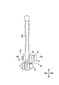
- the vehicle control device 1A of the first embodiment includes a holder 10, a brake lever 20A (“operator” in the claims), an operation amount detection device 50, a master cylinder 60, and a hydraulic pressure control device 100.
- the electronic control device 200A and the wheel brake B1 are provided.
- the wheel brake B1 of the vehicle control device 1A is a hydraulic disc brake in which a braking force is generated on the wheels when the pad sandwiches the disc by the brake hydraulic pressure acting on the wheel cylinder W.
- the holder 10 is divided into a holder main body 11 and a fixing member 12.
- the holder body 11 is arranged on the front side of the bar handle H
- the fixing member 12 is arranged on the rear side of the bar handle H
- the holder body 11 and the fixing member 12 are connected by bolts (not shown). There is.
- the holder 10 is fixed to the bar handle H by sandwiching the bar handle H between the holder body 11 and the fixing member 12.
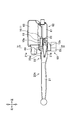
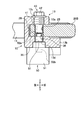
- a lever connecting portion 13 for connecting the brake lever 20A is formed on the front portion of the holder main body 11. As shown in FIG. 3, the lever connecting portion 13 is formed with an upper plate portion 13a and a lower plate portion 13b at intervals in the vertical direction. As shown in FIG. 4, a pivot fixing hole 13c penetrates the upper plate portion 13a in the vertical direction. The pivot fixing hole 13c is a screw hole into which the bolt portion 42 of the pivot 40, which will be described later, is screwed. A shaft insertion hole 13d penetrates the lower plate portion 13b in the vertical direction. The shaft insertion hole 13d is a through hole through which the detection shaft 52 described later is inserted. The central axis of the pivot fixing hole 13c and the central axis of the shaft insertion hole 13d are arranged on the same axis.
- the cylinder 61 of the master cylinder 60 and the reservoir 62 are integrally formed on the holder main body 11 of the first embodiment.
- the master cylinder 60 generates brake fluid pressure according to the force applied by the driver to the brake lever 20A.
- a piston (not shown) is inserted in the cylinder 61.
- the cylinder 61 is connected to the hydraulic pressure control device 100 via the pipe H1.
- the brake lever 20A includes a lever body 21, a knocker 22, and a grip allowance adjusting mechanism 23.
- the lever body 21 is a rod-shaped member arranged along the bar handle H, and is a portion operated by the driver with a finger. As shown in FIG. 3, an upper portion 21a and a lower portion 21b are formed at the base of the lever main body 21 at intervals in the vertical direction.
- the knocker 22 is a member that is connected to the base of the lever body 21 and is also connected to the master cylinder 60. A part of the knocker 22 is arranged between the upper portion 21a and the lower portion 21b of the lever main body 21. A protrusion (not shown) is formed on the side surface of the knocker 22. The protrusion is inserted into the cylinder 61 of the master cylinder 60 and is in contact with a piston (not shown) in the cylinder 61.
- a pivot insertion hole 25 having a circular shaft cross section penetrates the upper portion 21a, lower portion 21b, and knocker 22 of the lever body 21 in the vertical direction.
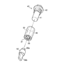
- An annular member 30 is press-fitted into the pivot insertion hole 25.
- the annular member 30 is a bottomed cylindrical cylinder (see FIG. 5).
- the annular member 30 is press-fitted into the pivot insertion hole 25 with the bottom portion 31 arranged on the lower side.
- the outer peripheral surface of the annular member 30 and the inner peripheral surface of the pivot insertion hole 25 are pressed against each other so that the annular member 30 and the brake lever 20A (lever body 21 and knocker 22) rotate together.
- the annular member 30 is formed with a bearing hole 32 having a circular shaft cross section.
- the bearing hole 32 is open on the upper end surface of the annular member 30.
- a fitting hole 33 having a polygonal shaft cross section penetrates in the vertical direction in the central portion of the bottom portion 31 of the annular member 30.
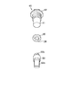
- the pivot 40 is a shaft member inserted into the pivot insertion hole 25.
- the pivot 40 is formed with a support shaft portion 41 having a circular shaft cross section and a bolt portion 42 formed on the base end side of the support shaft portion 41.
- the pivot 40 is inserted into the pivot fixing hole 13c of the holder body 11 from above, and the bolt portion 42 is screwed into the pivot fixing hole 13c. As a result, the pivot 40 is fixed to the holder body 11.
- the support shaft portion 41 of the pivot 40 is inserted into the bearing hole 32 of the annular member 30.
- the annular member 30 is rotatably connected to the support shaft portion 41 around the axis. In this way, the support shaft portion 41 of the pivot 40 is inserted into the pivot insertion hole 25.
- An annular member 30, a lever body 21, and a knocker 22 are rotatably connected to the support shaft portion 41 of the pivot 40 around the axis.
- the pivot 40 is fixed to the holder 10, and the lever body 21 and the knocker 22 of the brake lever 20A are rotatable around the axis of the pivot 40. It has become. Then, when the brake lever 20A is rotated from the initial position to the bar handle H side, the piston (not shown) of the master cylinder 60 is pushed by the knocker 22, and the brake fluid pressure is generated in the master cylinder 60.
- the brake lever 20A is provided with a grip allowance adjusting mechanism 23.
- the grip allowance adjusting mechanism 23 includes a dial 23a attached to the base of the lever body 21.
- a pin projects laterally from the dial 23a, and the tip of the pin is in contact with the side surface of the knocker 22.
- the grip allowance adjusting mechanism 23 is configured so that the amount of protrusion of the pin changes when the dial 23a is rotated.
- the position of the lever body 21 with respect to the knocker 22 can be changed around the axis of the pivot 40 by rotating the dial 23a.
- the distance (grip allowance) between the lever body 21 and the grip G of the bar handle H in the initial state of the brake lever 20A is adjusted. it can.
- the operation amount detecting device 50 detects the rotation amount of the brake lever 20A.
- the operation amount detecting device 50 includes a rotation angle sensor 51 fixed to the holder 10 and a detection shaft 52 fitted in the lower end of the pivot insertion hole 25.
- the detection shaft 52 is inserted into the shaft insertion hole 13d of the holder body 11.
- the detection shaft 52 is rotatable about an axis with respect to the shaft insertion hole 13d.
- the rotation center axis of the pivot 40 and the rotation center axis of the detection shaft 52 are arranged on the same axis.
- a fitting portion 52a projects from the center of the upper end surface of the detection shaft 52.
- the fitting portion 52a has a polygonal shaft cross section and is fitted into the fitting hole 33 of the annular member 30.
- the detection shaft 52 is fitted into the pivot insertion hole 25 via the annular member 30.
- the detection shaft 52, the annular member 30, the lever body 21, and the knocker 22 rotate together around the axis of the pivot 40.
- a detection unit 52b projects from the center of the lower end surface of the detection shaft 52.
- the detection unit 52b has a rectangular cross section.
- the rotation angle sensor 51 detects the rotation angle of the detection shaft 52.
- the rotation angle sensor 51 is fixed to the lower surface of the lower plate portion 13b of the holder body 11 by bolts (not shown).
- the detection unit 52b of the detection shaft 52 is inserted into the rotation angle sensor 51.
- the rotation angle sensor 51 is electrically connected to the electronic control device 200A described later.
- the amount of rotation of the brake lever 20A detected by the rotation angle sensor 51 is output to the electronic control device 200A.
- the initial position of the brake lever 20A is set in the operation amount detection device 50.
- the initial position of the brake lever 20A is the return position of the brake lever 20A after the brake lever 20A is operated and rotated a plurality of times with the brake lever 20A assembled to the bar handle H. In this way, by setting the initial position of the brake lever 20A in a state where each component of the vehicle control device 1A is familiarized, the amount of rotation of the brake lever 20A can be detected with high accuracy.
- the rotation angle sensor 51 detects the rotation angle of the detection shaft 52 that rotates in conjunction with the brake lever 20A to operate the brake lever 20A. The amount can be detected accurately.
- the detection shaft 52 since the detection shaft 52 is inserted into the pivot insertion hole 25 of the brake lever 20A, the detection shaft 52 and the rotation angle sensor 51 can be compactly arranged around the brake lever 20A. As a result, the detection shaft 52 can be downsized, and the operation amount detection device 50 can be lightened.
- the detection shaft 52 is arranged by using the pivot insertion hole 25 for rotating the brake lever 20A, a dedicated hole for attaching the detection shaft 52 is provided. There is no need to process the brake lever 20A.
- the shaft cross section of the fitting hole 33 of the annular member 30 and the fitting portion 52a of the detection shaft 52 is formed in a polygonal shape (see FIG. 5). In this configuration, by fitting the fitting portion 52a into the fitting hole 33, the annular member 30 and the detection shaft 52 can be reliably connected and rotated together.
- the annular member 30 is machined with a fitting hole 33 having a polygonal shaft cross section, and the annular member 30 is press-fitted into the pivot insertion hole 25. Therefore, the pivot insertion hole 25 Is easy to process. As a result, the processing cost of the brake lever 20A can be reduced. Further, since the lever body 21 and the knocker 22 are integrated by the annular member 30, the assembling work of the brake lever 20A becomes easy.
- the brake lever 20A is provided with the grip allowance adjusting mechanism 23, but the brake lever 20A may not be provided with the grip allowance adjusting mechanism 23. .. In this case, since it is not necessary to divide the brake lever 20A into the lever body 21 and the knocker 22, the brake lever 20A is composed of an integral member.
- the detection shaft 52 and the rotation angle sensor 51 are separately configured, but the rotation angle sensor 51 in which the detection shaft 52 is incorporated is incorporated. May be used.
- the detection shaft 52 is fitted into the fitting hole 33 of the annular member 30, but the detection shaft 52 may be directly fitted into the pivot insertion hole 25.
- the operation amount detecting device 50 applied to the hydraulic brake system having the brake lever 20A has been described, but the operation of the present invention is also described for the hydraulic brake system having the brake pedal.
- a quantity detector can be applied.
- the rotation amount of the brake lever 20A is detected, but the operation amount detection device of the present invention can be applied to various controls provided on the bar handle vehicle. ..
- the operation amount detecting device is configured to detect the rotation amount of the clutch lever
- the rotation amount of the clutch lever can be detected under various conditions such as when the bar handle vehicle is started, when the vehicle is running, and when the vehicle is stopped.
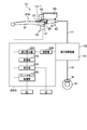
- the vehicle control device 1A of the first embodiment includes a hydraulic pressure control device 100 and an electronic control device 200A.
- the hydraulic pressure control device 100 can perform anti-lock brake control that suppresses wheel lock by increasing, depressurizing, or holding the brake hydraulic pressure of the wheel brake B1. Further, the hydraulic pressure control device 100 can also perform interlocking brake control in which a braking force is generated in the wheel brake B1 in conjunction with other wheel brakes.
- the hydraulic pressure control device 100 has a metal base 110, and a hydraulic passage is formed inside the base 110.
- a master cylinder 60 is connected to the inlet port of the base 110 via a pipe H1.
- a wheel cylinder W is connected to the outlet port of the base 110 via a pipe H2.
- a plurality of solenoid valves, an electric motor, and an electronic control device 200A are attached to the substrate 110.
- the electronic control device 200A is a microcomputer composed of a CPU (Central Processing Unit), a ROM (Read Only Memory), a RAM (Random Access Memory), and the like.
- the electronic control device 200A executes anti-lock brake control and also executes interlocking brake control by controlling the opening and closing of the solenoid valve of the hydraulic pressure control device 100 and the operation of the electric motor.
- the electronic control device 200A includes a storage unit 210, a hydraulic pressure calculation unit 220, a control unit 230, a determination unit 240, and a brake lamp control unit 250.
- the processing of each unit in the electronic control device 200A is embodied by executing the program stored in the storage unit 210 by the CPU.
- the storage unit 210 stores hydraulic pressure data showing the correspondence between the amount of rotation of the brake lever 20A and the brake hydraulic pressure generated from the master cylinder 60. Further, the storage unit 210 stores a specified amount of rotation of the brake lever 20A when the ignition switch IS is turned on.
- the hydraulic pressure calculation unit 220 estimates the brake hydraulic pressure generated from the master cylinder 60 based on the rotation amount of the brake lever 20A detected by the operation amount detecting device 50. In the hydraulic pressure calculation unit 220, when the rotation amount of the brake lever 20A is input from the operation amount detection device 50, the brake fluid pressure corresponding to the detected rotation amount is based on the hydraulic pressure data stored in the storage unit 210. Calculate the estimated value of. Then, the hydraulic pressure calculation unit 220 outputs the estimated value of the brake fluid pressure to the control unit 230.
- the control unit 230 controls the anti-lock brake by controlling the opening and closing of the solenoid valve of the hydraulic pressure control device 100 and the operation of the electric motor based on the estimated value of the brake fluid pressure input from the hydraulic pressure calculation unit 220. At the same time, the interlocking brake control is executed.
- the determination unit 240 determines the adjustment state of the wheel brake B1 based on the rotation amount of the brake lever 20A detected by the operation amount detection device 50 when the ignition switch IS is turned on.
- the storage unit 210 stores a specified amount of rotation of the brake lever 20A when the ignition switch IS is turned on. This specified amount is a brake in which when the driver rotates the brake lever 20A while the wheel brake B1 is normally adjusted, the operation feeling of the brake lever 20A becomes hard and the wheels are locked. This is the amount of rotation of the lever 20A.
- the wheel brake B1 is made to function by rotating the brake lever 20A when starting a drive unit such as an engine or a motor of a bar handle vehicle. At this time, the driver rotates the brake lever 20A to lock the wheels until the operation feeling of the brake lever 20A becomes hard.
- the determination unit 240 determines that the wheel brake B1 needs to be adjusted, and determines that the lamp or the lamp The judgment result is shown on the display unit such as a monitor.
- the determination unit 240 uses the wheel brake. It is determined that adjustment of B1 is necessary, and the determination result is shown on a display unit such as a lamp or a monitor.
- the brake lamp control unit 250 turns on and off the brake lamp BL based on the amount of rotation of the brake lever 20A detected by the operation amount detecting device 50.
- the brake lamp control unit 250 turns on the brake lamp BL when the amount of rotation of the brake lever 20A reaches a predetermined amount when the brake lever 20A is gripped. Further, when the brake lever 20A is returned and the amount of rotation of the brake lever 20A becomes smaller than a predetermined amount, the brake lamp BL is turned off.
- the brake fluid pressure generated from the master cylinder 60 can be detected without providing the hydraulic pressure sensor 100 in the hydraulic pressure control device 100, so that the number of parts of the hydraulic pressure control device 100 is reduced. it can. Further, in the vehicle control device 1A, the adjustment state of the wheel brake B1 can be determined and the brake lamp BL can be turned on with high accuracy based on the rotation amount of the brake lever 20A.
- the adjusted state of the wheel brake B1 can be determined based on the rotation amount of the brake lever 20A and the acceleration of the vehicle body. In this configuration, if the amount of rotation of the brake lever 20A is small but the decrease in the acceleration of the vehicle body detected by the acceleration sensor is large, the wheel brake B1 functions even when the brake lever 20A is not operated. Since there is a possibility that the wheel brake B1 has been adjusted, the determination unit 240 determines that the wheel brake B1 needs to be adjusted.
- the electronic control device can determine the adjustment state of the clutch based on the rotation amount of the clutch lever. ..
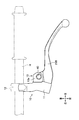
- the vehicle control device 1B of the second embodiment constitutes a mechanical brake system on the front wheel side or the rear wheel side of the bar handle vehicle.
- the vehicle control device 1B of the second embodiment includes a holder 10, a brake lever 20B (“operator” in the claims), an operation amount detection device 50, an electronic control device 200B, a wheel brake B2, and the like. It has.
- the wheel brake B2 of the vehicle control device 1B is a mechanical drum brake. In the wheel brake B2, when a tensile force is applied to the brake cable C (“connecting means” in the claims) by operating the brake lever 20B, the rod R tilts and the brake shoe moves to the inner peripheral surface of the drum. By being pressed, braking force is generated on the wheels.
- the base portion 28 of the brake lever 20B is arranged between the upper plate portion 13a and the lower plate portion 13b of the lever connecting portion 13 of the holder 10. There is. As shown in FIG. 6, one end of the brake cable C is connected to the base 28 of the brake lever 20B.
- a pivot insertion hole 25 penetrates the base 28 of the brake lever 20B in the vertical direction.
- An annular member 35 is inserted into the lower end of the pivot insertion hole 25.
- the annular member 35 of the second embodiment is an annular member.
- the annular member 35 is press-fitted into the lower end of the pivot insertion hole 25.
- the outer peripheral surface of the annular member 35 and the inner peripheral surface of the pivot insertion hole 25 are pressure-welded so that the annular member 35 and the brake lever 20B rotate together.
- a fitting hole 36 having a polygonal shaft cross section penetrates through the central portion of the annular member 35 of the second embodiment (see FIG. 10).
- the support shaft portion 41 is inserted into the pivot insertion hole 25, and the bolt portion 42 is screwed into the pivot fixing hole 13c.
- the base portion 28 of the brake lever 20B is rotatably connected to the support shaft portion 41 around the axis.
- the pivot 40 is fixed to the holder body 11, and the brake lever 20B is rotatable around the axis of the pivot 40. Then, when the brake lever 20B is rotated from the initial position to the bar handle H side, a tensile force is applied to the brake cable C to operate the wheel brake B2.
- the fitting portion 52a of the detection shaft 52 is fitted into the fitting hole 36 of the annular member 35. Then, in the operation amount detecting device 50, the rotation angle sensor 51 can detect the rotation amount of the brake lever 20B by detecting the rotation angle of the detection shaft 52. The amount of rotation of the brake lever 20B detected by the rotation angle sensor 51 is output to the electronic control device 200B.
- the vehicle control device 1B of the second embodiment includes an electronic control device 200B.
- the electronic control device 200B includes a storage unit 210, a tensile force calculation unit 260, a determination unit 240, and a brake lamp control unit 250.
- the storage unit 210 of the second embodiment stores tensile force data showing the relationship between the rotation amount of the brake lever 20B and the tensile force applied to the brake cable C.
- the tensile force calculation unit 260 estimates the tensile force applied to the brake cable C based on the amount of rotation of the brake lever 20B.
- the tensile force calculation unit 260 when the rotation amount of the brake lever 20B is input from the operation amount detection device 50, the tensile force corresponding to the detected rotation amount is calculated based on the tensile force data stored in the storage unit 210. Calculate the estimated value.
- the estimated value of the tensile force calculated by the tensile force calculation unit 260 is input to, for example, the control unit of the hydraulic pressure control device provided in the hydraulic brake system of another wheel, and is based on the estimated value of the tensile force. Interlocking brake control is executed.
- the determination unit 240 determines the adjustment state of the wheel brake B2 based on the rotation amount of the brake lever 20B, and the brake lamp control unit 250 accurately lights the brake lamp BL. be able to.
- the present invention can also be applied to a mechanical brake system, and the brake device 1B of the second embodiment has the same operation as the vehicle control device 1A (see FIG. 1) of the first embodiment. It has an effect.
- the vehicle control device 1B of the second embodiment of the present invention can be appropriately modified without departing from the spirit of the first embodiment.
- the brake lever 20B is composed of the lever body and the knocker to adjust the grip allowance, similarly to the vehicle control device 1A (see FIG. 2) of the first embodiment.
- a mechanism may be provided.
- the operation amount detecting device detects the rotation amount of the clutch lever, and the electronic control device determines the clutch adjustment state based on the rotation amount of the clutch lever. It may be configured.
- Vehicle control device (first embodiment) 1B Vehicle Control Device (Second Embodiment) 10 Holder 11 Holder body 13 Lever connecting part 13c Pivot fixing hole 13d Shaft insertion hole 20A Brake lever (first embodiment) 20B brake lever (second embodiment) 21 Lever body 22 Knocker 23 Grip allowance adjustment mechanism 23a Dial 25 Pivot insertion hole 30 Circular member (first embodiment) 31 Bottom 32 Bearing hole 33 Fitting hole 35 Ring member (second embodiment) 36 Fitting hole 40 Pivot 41 Support shaft 42 Bolt 50 Operation amount detector 51 Rotation angle sensor 52 Detection shaft 52a Fitting 52b Detection 60 Master cylinder 61 Cylinder 62 Reservoir 100 Hydraulic control device 110 Base 200A Electronic control device (First Embodiment) 200B electronic control device (second embodiment) 210 Storage unit 220 Hydraulic pressure calculation unit 230 Control unit 240 Judgment unit 250 Brake lamp control unit 260 Tensile force calculation unit B1 Wheel brake (first embodiment) B2 wheel brake (second embodiment) BL Brake Lamp C
Landscapes
- Engineering & Computer Science (AREA)
- Mechanical Engineering (AREA)
- Transportation (AREA)
- General Engineering & Computer Science (AREA)
- Braking Elements And Transmission Devices (AREA)
- Transmission Of Braking Force In Braking Systems (AREA)
- Mechanical Control Devices (AREA)
Abstract
L'invention concerne un dispositif de commande (1A) pour un véhicule, comprenant un dispositif de détection de degré d'actionnement (50), un dispositif de commande de pression hydraulique (100), et un dispositif de commande électronique (200A). Le dispositif de détection de degré d'actionnement (50) détecte un degré de rotation d'un levier de frein (20A) par l'intermédiaire d'un capteur d'angle de rotation (51). Le dispositif de commande électronique (200A) est pourvu d'une unité de calcul de pression hydraulique (220) qui estime la pression hydraulique de frein générée à partir d'un maître-cylindre (60) en fonction du degré de rotation du levier de frein (20A), et d'une unité de commande (230) qui commande le dispositif de commande de pression hydraulique (100) en fonction de la valeur estimée de pression hydraulique de frein. Avec ladite configuration, la puissance motrice générée par le fonctionnement du levier de frein (20A) peut être détectée, le nombre d'éléments dans le véhicule à guidon étant réduit.
Priority Applications (3)
| Application Number | Priority Date | Filing Date | Title |
|---|---|---|---|
| CN202080053319.4A CN114174164A (zh) | 2019-07-31 | 2020-06-25 | 操纵手柄车辆用控制装置 |
| EP20848117.6A EP4005914A4 (fr) | 2019-07-31 | 2020-06-25 | Dispositif de commande pour véhicule à guidon |
| JP2021536842A JPWO2021019979A1 (fr) | 2019-07-31 | 2020-06-25 |
Applications Claiming Priority (2)
| Application Number | Priority Date | Filing Date | Title |
|---|---|---|---|
| JP2019-140826 | 2019-07-31 | ||
| JP2019140826 | 2019-07-31 |
Publications (1)
| Publication Number | Publication Date |
|---|---|
| WO2021019979A1 true WO2021019979A1 (fr) | 2021-02-04 |
Family
ID=74230568
Family Applications (1)
| Application Number | Title | Priority Date | Filing Date |
|---|---|---|---|
| PCT/JP2020/024968 WO2021019979A1 (fr) | 2019-07-31 | 2020-06-25 | Dispositif de commande pour véhicule à guidon |
Country Status (5)
| Country | Link |
|---|---|
| EP (1) | EP4005914A4 (fr) |
| JP (1) | JPWO2021019979A1 (fr) |
| CN (1) | CN114174164A (fr) |
| TW (1) | TW202110679A (fr) |
| WO (1) | WO2021019979A1 (fr) |
Citations (3)
| Publication number | Priority date | Publication date | Assignee | Title |
|---|---|---|---|---|
| JP2007091148A (ja) * | 2005-09-30 | 2007-04-12 | Honda Motor Co Ltd | 車両 |
| JP2016175545A (ja) * | 2015-03-20 | 2016-10-06 | 日信工業株式会社 | バーハンドル車両用操作量検出装置 |
| JP2016193652A (ja) * | 2015-03-31 | 2016-11-17 | オートリブ日信ブレーキシステムジャパン株式会社 | 車両用ブレーキ液圧制御装置 |
Family Cites Families (7)
| Publication number | Priority date | Publication date | Assignee | Title |
|---|---|---|---|---|
| ITMI20052240A1 (it) * | 2005-11-23 | 2007-05-24 | Freni Brembo Spa | Dispositivo a leva per l'azionamento di un attuatore idraulico |
| JP5460557B2 (ja) * | 2010-11-05 | 2014-04-02 | 本田技研工業株式会社 | アンチロックブレーキ制御装置 |
| DE102013200422A1 (de) * | 2013-01-14 | 2014-07-17 | Robert Bosch Gmbh | Hydraulisches Antiblockiersystem für ein Zweirad |
| DE102013200419A1 (de) * | 2013-01-14 | 2014-07-31 | Robert Bosch Gmbh | Hydraulikmodul für ein Antiblockiersystem für ein Zweirad |
| WO2014147976A1 (fr) * | 2013-03-22 | 2014-09-25 | ヤマハ発動機株式会社 | Dispositif de commande de frein et véhicule de type à selle comprenant ce dernier |
| JP6420199B2 (ja) * | 2015-04-28 | 2018-11-07 | 株式会社シマノ | 自転車用装置 |
| IT201600111289A1 (it) * | 2016-11-04 | 2018-05-04 | Blubrake S R L | Sistema per l’assistenza alla frenata da parte di un ciclista su una bicicletta |
-
2020
- 2020-06-25 EP EP20848117.6A patent/EP4005914A4/fr active Pending
- 2020-06-25 JP JP2021536842A patent/JPWO2021019979A1/ja active Pending
- 2020-06-25 CN CN202080053319.4A patent/CN114174164A/zh active Pending
- 2020-06-25 WO PCT/JP2020/024968 patent/WO2021019979A1/fr unknown
- 2020-07-28 TW TW109125363A patent/TW202110679A/zh unknown
Patent Citations (3)
| Publication number | Priority date | Publication date | Assignee | Title |
|---|---|---|---|---|
| JP2007091148A (ja) * | 2005-09-30 | 2007-04-12 | Honda Motor Co Ltd | 車両 |
| JP2016175545A (ja) * | 2015-03-20 | 2016-10-06 | 日信工業株式会社 | バーハンドル車両用操作量検出装置 |
| JP2016193652A (ja) * | 2015-03-31 | 2016-11-17 | オートリブ日信ブレーキシステムジャパン株式会社 | 車両用ブレーキ液圧制御装置 |
Non-Patent Citations (1)
| Title |
|---|
| See also references of EP4005914A4 * |
Also Published As
| Publication number | Publication date |
|---|---|
| EP4005914A4 (fr) | 2023-12-13 |
| JPWO2021019979A1 (fr) | 2021-02-04 |
| TW202110679A (zh) | 2021-03-16 |
| CN114174164A (zh) | 2022-03-11 |
| EP4005914A1 (fr) | 2022-06-01 |
Similar Documents
| Publication | Publication Date | Title |
|---|---|---|
| CN108367743B (zh) | 液压控制装置、液压式制动系统及自行车 | |
| TWI432360B (zh) | Bicycle brake lever and the use of its bicycle with kinetic energy recovery brake control device | |
| US9068579B2 (en) | Brake system of straddle type vehicle | |
| TWI818951B (zh) | 控制裝置及煞車系統 | |
| WO2021019978A1 (fr) | Dispositif de détection de quantité d'opération pour véhicule à guidon | |
| US10661859B2 (en) | Lever apparatus | |
| JPWO2017103703A1 (ja) | 液圧式ブレーキシステム、自転車、及び、液圧式ブレーキシステムの制御方法 | |
| WO2021019979A1 (fr) | Dispositif de commande pour véhicule à guidon | |
| WO2021019980A1 (fr) | Dispositif de détection de valeur d'actionnement pour véhicule à guidon | |
| JP4367051B2 (ja) | 電気ブレーキシステム | |
| JP3790025B2 (ja) | 二輪車用ブレーキ装置 | |
| JP3586434B2 (ja) | ペダル装置 | |
| JP7454580B2 (ja) | 車両用ブレーキ装置 | |
| JP2007091201A (ja) | 自動二輪車のブレーキ装置 | |
| JP6832472B2 (ja) | レバー装置 | |
| KR20210093018A (ko) | 차량의 핸들 타입 통합 제어장치 | |
| JP4234237B2 (ja) | 二輪車用ブレーキ装置 | |
| JP4350282B2 (ja) | バーハンドル車両用操作レバーの握り代調整機構 | |
| JP2627452B2 (ja) | アンチロックブレーキ用モジュレータ | |
| EP2586669B1 (fr) | Système de freinage pour motocyclette | |
| KR100379680B1 (ko) | 액셀레이터 페달 모듈 | |
| JPH11287265A (ja) | ディスクブレーキ | |
| JP2008126989A (ja) | バーハンドル車両用液圧マスタシリンダ装置 | |
| JPH0437834Y2 (fr) | ||
| JPH0939868A (ja) | バーハンドル車両用液圧マスタシリンダ装置の操作レバー |
Legal Events
| Date | Code | Title | Description |
|---|---|---|---|
| 121 | Ep: the epo has been informed by wipo that ep was designated in this application |
Ref document number: 20848117 Country of ref document: EP Kind code of ref document: A1 |
|
| ENP | Entry into the national phase |
Ref document number: 2021536842 Country of ref document: JP Kind code of ref document: A |
|
| NENP | Non-entry into the national phase |
Ref country code: DE |
|
| ENP | Entry into the national phase |
Ref document number: 2020848117 Country of ref document: EP Effective date: 20220228 |