WO2021015184A1 - 車両用灯具、及び車両用前照灯 - Google Patents
車両用灯具、及び車両用前照灯 Download PDFInfo
- Publication number
- WO2021015184A1 WO2021015184A1 PCT/JP2020/028201 JP2020028201W WO2021015184A1 WO 2021015184 A1 WO2021015184 A1 WO 2021015184A1 JP 2020028201 W JP2020028201 W JP 2020028201W WO 2021015184 A1 WO2021015184 A1 WO 2021015184A1
- Authority
- WO
- WIPO (PCT)
- Prior art keywords
- light
- control surface
- light source
- reflection control
- reflection
- Prior art date
- Legal status (The legal status is an assumption and is not a legal conclusion. Google has not performed a legal analysis and makes no representation as to the accuracy of the status listed.)
- Ceased
Links
Images




Classifications
-
- F—MECHANICAL ENGINEERING; LIGHTING; HEATING; WEAPONS; BLASTING
- F21—LIGHTING
- F21S—NON-PORTABLE LIGHTING DEVICES; SYSTEMS THEREOF; VEHICLE LIGHTING DEVICES SPECIALLY ADAPTED FOR VEHICLE EXTERIORS
- F21S41/00—Illuminating devices specially adapted for vehicle exteriors, e.g. headlamps
- F21S41/10—Illuminating devices specially adapted for vehicle exteriors, e.g. headlamps characterised by the light source
- F21S41/14—Illuminating devices specially adapted for vehicle exteriors, e.g. headlamps characterised by the light source characterised by the type of light source
- F21S41/141—Light emitting diodes [LED]
- F21S41/147—Light emitting diodes [LED] the main emission direction of the LED being angled to the optical axis of the illuminating device
-
- F—MECHANICAL ENGINEERING; LIGHTING; HEATING; WEAPONS; BLASTING
- F21—LIGHTING
- F21S—NON-PORTABLE LIGHTING DEVICES; SYSTEMS THEREOF; VEHICLE LIGHTING DEVICES SPECIALLY ADAPTED FOR VEHICLE EXTERIORS
- F21S41/00—Illuminating devices specially adapted for vehicle exteriors, e.g. headlamps
- F21S41/20—Illuminating devices specially adapted for vehicle exteriors, e.g. headlamps characterised by refractors, transparent cover plates, light guides or filters
- F21S41/25—Projection lenses
-
- F—MECHANICAL ENGINEERING; LIGHTING; HEATING; WEAPONS; BLASTING
- F21—LIGHTING
- F21S—NON-PORTABLE LIGHTING DEVICES; SYSTEMS THEREOF; VEHICLE LIGHTING DEVICES SPECIALLY ADAPTED FOR VEHICLE EXTERIORS
- F21S41/00—Illuminating devices specially adapted for vehicle exteriors, e.g. headlamps
- F21S41/30—Illuminating devices specially adapted for vehicle exteriors, e.g. headlamps characterised by reflectors
- F21S41/32—Optical layout thereof
- F21S41/36—Combinations of two or more separate reflectors
- F21S41/365—Combinations of two or more separate reflectors successively reflecting the light
-
- F—MECHANICAL ENGINEERING; LIGHTING; HEATING; WEAPONS; BLASTING
- F21—LIGHTING
- F21S—NON-PORTABLE LIGHTING DEVICES; SYSTEMS THEREOF; VEHICLE LIGHTING DEVICES SPECIALLY ADAPTED FOR VEHICLE EXTERIORS
- F21S41/00—Illuminating devices specially adapted for vehicle exteriors, e.g. headlamps
- F21S41/60—Illuminating devices specially adapted for vehicle exteriors, e.g. headlamps characterised by a variable light distribution
- F21S41/67—Illuminating devices specially adapted for vehicle exteriors, e.g. headlamps characterised by a variable light distribution by acting on reflectors
- F21S41/675—Illuminating devices specially adapted for vehicle exteriors, e.g. headlamps characterised by a variable light distribution by acting on reflectors by moving reflectors
-
- F—MECHANICAL ENGINEERING; LIGHTING; HEATING; WEAPONS; BLASTING
- F21—LIGHTING
- F21S—NON-PORTABLE LIGHTING DEVICES; SYSTEMS THEREOF; VEHICLE LIGHTING DEVICES SPECIALLY ADAPTED FOR VEHICLE EXTERIORS
- F21S45/00—Arrangements within vehicle lighting devices specially adapted for vehicle exteriors, for purposes other than emission or distribution of light
- F21S45/10—Protection of lighting devices
-
- F—MECHANICAL ENGINEERING; LIGHTING; HEATING; WEAPONS; BLASTING
- F21—LIGHTING
- F21V—FUNCTIONAL FEATURES OR DETAILS OF LIGHTING DEVICES OR SYSTEMS THEREOF; STRUCTURAL COMBINATIONS OF LIGHTING DEVICES WITH OTHER ARTICLES, NOT OTHERWISE PROVIDED FOR
- F21V14/00—Controlling the distribution of the light emitted by adjustment of elements
- F21V14/04—Controlling the distribution of the light emitted by adjustment of elements by movement of reflectors
-
- F—MECHANICAL ENGINEERING; LIGHTING; HEATING; WEAPONS; BLASTING
- F21—LIGHTING
- F21V—FUNCTIONAL FEATURES OR DETAILS OF LIGHTING DEVICES OR SYSTEMS THEREOF; STRUCTURAL COMBINATIONS OF LIGHTING DEVICES WITH OTHER ARTICLES, NOT OTHERWISE PROVIDED FOR
- F21V14/00—Controlling the distribution of the light emitted by adjustment of elements
- F21V14/06—Controlling the distribution of the light emitted by adjustment of elements by movement of refractors
-
- F—MECHANICAL ENGINEERING; LIGHTING; HEATING; WEAPONS; BLASTING
- F21—LIGHTING
- F21V—FUNCTIONAL FEATURES OR DETAILS OF LIGHTING DEVICES OR SYSTEMS THEREOF; STRUCTURAL COMBINATIONS OF LIGHTING DEVICES WITH OTHER ARTICLES, NOT OTHERWISE PROVIDED FOR
- F21V5/00—Refractors for light sources
-
- F—MECHANICAL ENGINEERING; LIGHTING; HEATING; WEAPONS; BLASTING
- F21—LIGHTING
- F21V—FUNCTIONAL FEATURES OR DETAILS OF LIGHTING DEVICES OR SYSTEMS THEREOF; STRUCTURAL COMBINATIONS OF LIGHTING DEVICES WITH OTHER ARTICLES, NOT OTHERWISE PROVIDED FOR
- F21V7/00—Reflectors for light sources
-
- F—MECHANICAL ENGINEERING; LIGHTING; HEATING; WEAPONS; BLASTING
- F21—LIGHTING
- F21V—FUNCTIONAL FEATURES OR DETAILS OF LIGHTING DEVICES OR SYSTEMS THEREOF; STRUCTURAL COMBINATIONS OF LIGHTING DEVICES WITH OTHER ARTICLES, NOT OTHERWISE PROVIDED FOR
- F21V7/00—Reflectors for light sources
- F21V7/04—Optical design
- F21V7/08—Optical design with elliptical curvature
-
- F—MECHANICAL ENGINEERING; LIGHTING; HEATING; WEAPONS; BLASTING
- F21—LIGHTING
- F21V—FUNCTIONAL FEATURES OR DETAILS OF LIGHTING DEVICES OR SYSTEMS THEREOF; STRUCTURAL COMBINATIONS OF LIGHTING DEVICES WITH OTHER ARTICLES, NOT OTHERWISE PROVIDED FOR
- F21V9/00—Elements for modifying spectral properties, polarisation or intensity of the light emitted, e.g. filters
- F21V9/06—Elements for modifying spectral properties, polarisation or intensity of the light emitted, e.g. filters for filtering out ultraviolet radiation
-
- F—MECHANICAL ENGINEERING; LIGHTING; HEATING; WEAPONS; BLASTING
- F21—LIGHTING
- F21V—FUNCTIONAL FEATURES OR DETAILS OF LIGHTING DEVICES OR SYSTEMS THEREOF; STRUCTURAL COMBINATIONS OF LIGHTING DEVICES WITH OTHER ARTICLES, NOT OTHERWISE PROVIDED FOR
- F21V9/00—Elements for modifying spectral properties, polarisation or intensity of the light emitted, e.g. filters
- F21V9/40—Elements for modifying spectral properties, polarisation or intensity of the light emitted, e.g. filters with provision for controlling spectral properties, e.g. colour, or intensity
Definitions
- the present invention relates to vehicle lighting fixtures and vehicle headlights.
- vehicle lighting equipment As vehicle lighting equipment, vehicle headlights typified by automobile headlights, drawing devices for drawing images on road surfaces, etc. are known. By the way, various configurations have been studied in order to obtain a desired image as a projected image in a vehicle lamp.
- Patent Document 1 discloses a vehicle lighting fixture including one light emitting optical system that emits light and a reflecting device that reflects light emitted from the light emitting optical system.
- This reflecting device is a so-called DMD (Digital Mirror Device), has a reflection control surface composed of reflecting surfaces of a plurality of reflecting elements whose tilting states can be individually switched, and emits light emitted from a light emitting optical system. It is reflected by the reflection control surface to form a light distribution pattern according to the tilted state of the plurality of reflecting elements. Therefore, it is said that the vehicle lamp can emit light having a predetermined light distribution pattern by controlling the tilted state of the plurality of reflecting elements.
- the vehicle lighting fixture is a vehicle headlight that includes a lens and irradiates the front of the vehicle with light having a predetermined light distribution pattern through the lens.
- the vehicle lighting equipment has a reflection control surface composed of a plurality of light emitting optical systems that emit light and a reflection surface of a plurality of reflection elements that can individually switch the tilting state.
- a reflection control surface composed of a plurality of light emitting optical systems that emit light and a reflection surface of a plurality of reflection elements that can individually switch the tilting state.
- Each of the light emitted from the plurality of light emitting optical systems is reflected by the reflection control surface to form a light distribution pattern corresponding to the tilted state of the plurality of reflecting elements.
- the light intensity distributions in at least two irradiation patterns are different from each other.
- the vehicle lamp of the first aspect can emit light having a predetermined light distribution pattern by controlling the tilted state of a plurality of reflecting elements in the reflecting device.
- the light intensity distribution on the reflection control surface depends on the light intensity distribution emitted from the light emitting optical system
- the light intensity distribution in the formed light distribution pattern is the light intensity distribution emitted from the light emitting optical system. Tends to be affected by.
- the reflection control surface is irradiated with the light emitted from the plurality of light emitting optical systems.
- the vehicle lighting fixture of the first aspect improves the degree of freedom of light intensity distribution on the reflection control surface as compared with the case where the light emitted from one light emitting optical system is applied to the reflection control surface. It is possible to improve the degree of freedom of light intensity distribution in the light distribution pattern of the obtained and emitted light. Further, in the vehicle lamp of the first aspect, as described above, among the irradiation patterns on the reflection control surface of each light emitted from each of the plurality of light emitting optical systems and irradiated on the reflection control surface. The light intensity distributions in at least two irradiation patterns are different from each other.
- the vehicle lighting fixture of the first aspect can improve the degree of freedom of the light intensity distribution on the reflection control surface as compared with the case where the light intensity distributions in at least two irradiation patterns are the same, and the emitted light can be improved. It is possible to improve the degree of freedom of light intensity distribution in the light distribution pattern of.
- the maximum value of the light intensity in the at least two irradiation patterns may be different from each other.
- the degree of freedom of the light intensity distribution on the reflection control surface can be improved as compared with the case where the maximum value of the light intensity in at least two irradiation patterns is the same, and the light distribution of the emitted light can be improved.
- the degree of freedom of light intensity distribution in the pattern can be improved.
- the half widths of the light intensity distributions in the at least two irradiation patterns may be different from each other.
- the degree of freedom of the light intensity distribution on the reflection control surface can be improved as compared with the case where the half-value widths of the light intensity distributions in at least two irradiation patterns are the same, and the arrangement of the emitted light can be improved.
- the degree of freedom of intensity distribution in the light pattern can be improved.
- At least a part of the at least two irradiation patterns may overlap each other.
- the light in the light distribution pattern of the emitted light is compared with the case where at least two irradiation patterns do not overlap.
- the maximum value of intensity can be increased.
- the irradiation pattern is a pattern formed by light having an intensity of 0.0025 times or more of the maximum value among the irradiated lights. Further, when such light is applied to the entire reflection control surface, the outer shape of the irradiation pattern on the reflection control surface becomes the outer shape of the reflection control surface.
- only a part of the at least two irradiation patterns may overlap.
- the entire at least one irradiation pattern in the at least two irradiation patterns and at least a part of the other at least one irradiation pattern in the at least two irradiation patterns may overlap each other.
- the regions having the highest light intensity in the at least two irradiation patterns may not overlap each other.
- the light intensity distribution on the reflection control surface may be an intensity distribution having at least two peaks, or the maximum value of the light intensity distribution on the reflection control surface may be unintentionally increased. Can be suppressed.
- the light intensity distribution in the light distribution pattern of the emitted light is set to an intensity distribution having at least two peaks, or the maximum value of the light intensity distribution in the light distribution pattern of the emitted light is unintentionally increased. Can be suppressed.
- the regions having the highest light intensity in the at least two irradiation patterns may overlap each other.
- the maximum value in the light intensity distribution on the reflection control surface can be increased as compared with the case where the regions having the highest intensity do not overlap each other, and the light of the light distribution pattern of the emitted light can be increased.
- the maximum value in the intensity distribution of can be increased. Therefore, it is particularly useful when the maximum value in the light intensity distribution of at least two irradiation patterns is smaller than the maximum value in the light intensity distribution of the emitted light distribution pattern.
- At least one light emitting optical system in the at least two light emitting optical systems collects a light source and light emitted from the light source and irradiates the reflection control surface with the light source. It may have a member.
- the amount of light emitted to the reflection control surface can be increased and the energy efficiency can be improved as compared with the case where the light emitting optical system does not have a condensing member.
- the vehicle lighting fixture of the first aspect further includes a projection lens that adjusts the divergence angle of light that is emitted from the reflection control surface and forms a light distribution pattern according to the tilted state of the plurality of reflecting elements. May be good.
- the vehicle lighting equipment reflects the first light source, the first reflector that reflects the light emitted from the first light source, the second light source, and the light emitted from the second light source. It has a second reflector and a reflecting surface that reflects light emitted from the first light source and reflected by the first reflector and light emitted from the second light source and reflected by the second reflector.
- the reflecting device comprises a reflecting device that forms a predetermined light distribution pattern by the light reflected by the first light source, and at least a part of the reflecting surface of the first reflector is directed from the first light source side to the second light source side.
- At least a part of the reflecting surface of the second reflector is inclined so as to approach the reflecting surface of the reflecting device from the second light source side toward the first light source side.
- a plane is viewed as a plane, passing through the first light source and the second light source and perpendicular to the reflection surface of the reflector, the optical axis of the first light source and the optical axis of the second light source Is characterized by the intersection of.
- light having a predetermined light distribution pattern is formed by the light reflected by the reflecting surface of the reflecting device.
- at least a part of the reflecting surface of the first reflector approaches the reflecting surface of the reflecting device from the first light source side toward the second light source side.
- At least a part of the reflection surface of the second reflector is a surface that is inclined so as to approach the reflection surface of the reflector as it goes from the second light source side to the first light source side, and is the first light source and the second light source.
- the optical axis of the first light source and the optical axis of the second light source intersect. Therefore, even if the distance between the first light source and the second light source is increased, the propagation direction of the light emitted from the first light source and reflected by the reflecting surface of the first reflector is emitted from the second light source and second. It can be made closer to the direction parallel to the propagation direction of the light reflected by the reflecting surface of the reflector.
- the vehicle lighting fixture of the second aspect can suppress the overheating of the light source and the darkening of the light distribution pattern of the emitted light.
- vehicle lighting fixture of the second aspect may further include a projection lens that adjusts the divergence angle of light emitted from the reflecting device to form the predetermined light distribution pattern.
- the vehicle lamp of the second aspect includes a projection lens, at least one part of the first reflector and the second reflector and an incident surface of the projection lens in a direction along the optical axis of the projection lens. It is also possible that a part of the above overlaps with each other.
- the light emitted from the reflecting device can be emitted from the projection lens as compared with the case where the first reflector and the second reflector and the incident surface of the projection lens do not overlap in the direction along the optical axis of the projection lens. It is possible to suppress passing through the gap between the incident surface and the first reflector and the gap between the incident surface of the projection lens and the second reflector, and it is possible to suppress the emission of light in an unintended direction.
- the vehicle lighting equipment of the second aspect includes a projection lens
- a surface that is inclined away from the optical axis of the projection lens as it passes through the projection lens and goes from the entrance surface side to the emission surface side of the projection lens is used as a reference.
- the side of the projection lens opposite to the optical axis side of the projection lens may be cut out.
- the member can be arranged in the space formed by cutting out the projection lens, so that the vehicle lamp can be miniaturized.
- the surface formed on the projection lens by cutting out the projection lens is tilted away from the optical axis of the projection lens from the entrance surface side to the emission surface side. Therefore, when the surface formed on the projection lens by cutting out the projection lens is parallel to the optical axis of the projection lens, or tilts toward the optical axis of the projection lens from the entrance surface side to the emission surface side. As compared with the case, it is possible to suppress the light incident on the projection lens from being reflected by this surface, and it is possible to suppress the light being emitted in an unintended direction.
- the first light source and the first light source are viewed in a plan view when the surface perpendicular to the reflection surface of the reflector passes through the first light source and the second light source.
- the reflectors may overlap each other.
- the divergence angle of the light emitted from the light source is about 180 degrees. Therefore, in the case of plan view as described above, the amount of light emitted from the first light source and not reflected by the first reflector is reduced as compared with the case where the first light source and the first reflector do not overlap each other. It is possible to suppress the emission of light in an unintended direction.
- the reflecting surface of the reflecting device is composed of the reflecting surfaces of a plurality of reflecting elements whose tilting states can be individually switched, and the tilting state of the plurality of reflecting elements is determined. It may be in a state corresponding to the predetermined light distribution pattern.
- the light distribution pattern of the emitted light can be changed by controlling the tilted state of a plurality of reflecting elements constituting the reflecting surface of the reflecting device.
- the light source and the light emitted from the light source enter the flat incident surface and emit light having a predetermined light distribution pattern from the flat exit surface.
- a light distribution pattern forming unit and a projection optical system including at least one lens to magnify and project the predetermined light distribution pattern are provided, and the projection optical system is on the outer peripheral side of the predetermined light distribution pattern. It is characterized in that the predetermined light distribution pattern is enlarged and projected so that the enlargement ratio of the region is larger than the enlargement ratio of the region on the central side.
- the light intensity on the central side of the light distribution pattern tends to be higher than the light intensity on the outer peripheral side.
- the enlargement ratio of the outer peripheral region in the predetermined light distribution pattern formed by the light distribution pattern forming portion is the central region.
- a predetermined light distribution pattern is enlarged and projected so as to be larger than the magnification of. Therefore, in the light distribution pattern projected by the vehicle headlight of the third aspect, the predetermined light distribution pattern formed by the light distribution pattern forming portion is expanded and the outer circumference of the predetermined light distribution pattern is expanded.
- the light distribution pattern is such that the extension of the region on the central side of the region on the side is suppressed. Therefore, the vehicle headlight of the third aspect can reduce the intensity of light on the central side of the incident surface of the light distribution pattern forming portion, and suppress the concentration of heat on the central portion of the incident surface. Can improve durability.
- the distance to the reference point is r1
- the distance between the focal point and the second reference point located on the focal plane is r2
- the distance between the focal point and the third reference point located on the focal plane is r3.
- the tilt angle of the light passing through the main point when the first reference point and the projection optical system are approximated by a thin lens in the emission direction from the projection optical system with respect to the optical axis of the projection optical system is set to ⁇ 1
- the second The tilt angle of the light passing through the reference point and the main point from the projection optical system with respect to the optical axis is ⁇ 2
- Such a projection optical system is arranged so that the optical axis of the projection optical system passes through the central portion of the light source image and the light source image is located on or near the focal plane of the projection optical system.
- An enlarged image of the light source image can be imaged at infinity or the like so that the magnification of the outer peripheral region of the light source image is larger than the magnification of the central region. Therefore, in the vehicle headlight of the third aspect, the enlargement ratio of the outer peripheral region in the predetermined light distribution pattern formed by the light distribution pattern forming portion is larger than the enlargement ratio of the central region.
- a light distribution pattern in which the predetermined light distribution pattern is enlarged can be imaged at infinity or the like.
- the second reference point has the inclination angle ⁇ 2 with respect to the optical axis in the emission direction of the light passing through the second reference point and the principal point from the projection optical system in the equation (1) and the following equation (1). It may be a reference point that is the same as the angle ⁇ 2 when 3) holds.
- a light distribution pattern in which the entire predetermined light distribution pattern formed by the light distribution pattern forming portion is enlarged at a constant magnification can be imaged at infinity or the like. ..
- the angle ⁇ 1 is smaller and the angle ⁇ 3 is larger than in this case. Therefore, in the vehicle headlight of the third aspect, the extension of the central region of the projected light distribution pattern is suppressed as compared with the above case, and the center of the incident surface of the light distribution pattern forming portion is suppressed. The intensity of light on the side can be lowered, and the concentration of heat on the central portion of the incident surface can be suppressed to improve durability.
- the light distribution pattern forming portion is composed of the reflecting surfaces of a plurality of reflecting elements whose tilting states can be individually switched, and also serves as the incident surface and the emitting surface. It may have a planar reflection control surface, and the light emitted from the light source may be reflected by the reflection control surface to emit light having the predetermined light distribution pattern.
- the light distribution pattern of the emitted light can be changed by controlling the tilting state of the plurality of reflecting elements constituting the reflection control surface.
- the outer edge of the image of the light emitted from the reflection control surface and incident on the projection optical system on the reflection control surface may be separated from the outer edge of the reflection control surface.
- this vehicle headlight of the third aspect light of a predetermined light distribution pattern is emitted from the reflection control surface of the light distribution pattern forming portion, and this light is incident on the projection optical system. Therefore, the image on the reflection control surface of the light incident on the projection optical system has a predetermined light distribution pattern.
- the outer edge of this image is separated from the outer edge of the reflection control surface. Therefore, in the vehicle headlight of the third aspect, the light distribution pattern forming unit is compared with the case where the outer edge of the image on the reflection control surface of the light incident on the projection optical system coincides with the outer edge of the reflection control surface. It is possible to improve the degree of freedom of the outer shape of a predetermined light distribution pattern emitted from the light source.
- the enlargement ratio of the outer peripheral region in the predetermined light distribution pattern formed by the light distribution pattern forming portion is on the center side.
- a predetermined light distribution pattern is projected so as to be larger than the magnification of the region of. Therefore, the outer shape of the light distribution pattern projected on the front of the vehicle by the vehicle headlight of the third aspect is different from the outer shape of the predetermined light distribution pattern formed by the light distribution pattern forming portion. Therefore, compared to the case where the outer edge of the image on the reflection control surface of the light incident on the projection optical system coincides with the outer edge of the reflection control surface, the outer shape of the light distribution pattern projected on the front of the vehicle by the vehicle headlight is changed. It is easy to make a desired shape.
- FIG. 1st Embodiment of this invention It is a front view which shows the outline of the vehicle provided with the vehicle lamp according to the 1st Embodiment of this invention. It is a cross-sectional view in the horizontal direction of one lamp unit in line II-II of FIG. It is a perspective view which shows typically the light emitting part shown in FIG. It is a side view which shows typically the light emitting part shown in FIG. It is a figure which shows schematic cross section in the thickness direction of a part of the reflection part shown in FIG. It is a front view which shows typically the reflector shown in FIG. It is a figure which shows schematic the irradiation pattern of the light from the 1st emission optical system which irradiates a reflector, and the intensity distribution of the light in the irradiation pattern.
- Is shown in the same manner as in FIG. It is a figure which shows another part of the light distribution pattern of the high beam shown in FIG.
- FIG. It is a perspective view which shows typically the light emitting part shown in FIG. It is a side view which shows typically the light emitting part shown in FIG. It is a front view schematically showing the projection lens shown in FIG. It is a figure which shows schematicly the headlight for a vehicle of 4th Embodiment of this invention. It is a figure for demonstrating the propagation of light in a projection optical system. It is a figure which shows schematic the irradiation pattern of the light which irradiates the reflector as a light distribution pattern forming part. It is a figure which shows schematic the image on the reflection control surface of the light emitted from the reflection control surface and incident on a lens.
- FIG. 1 is a front view showing an outline of a vehicle provided with a vehicle lamp according to the present embodiment.
- the vehicle lighting fixture of the present embodiment is a vehicle headlight 1, and is used for an automobile.
- the vehicle 100 includes a pair of vehicle headlights 1 in each of the front left and right directions.
- the pair of vehicle headlights 1 provided in the vehicle 100 have a shape symmetrical to each other in the left-right direction.
- a plurality of lamp units 1a, 1b, 1c are arranged side by side with each other, the lamp unit 1a is arranged on the outermost side of the vehicle 100, and the lamp unit 1c is the vehicle 100. It is arranged on the most central side, and the lamp unit 1b is arranged between the lamp unit 1a and the lamp unit 1c.
- the lamp unit 1a and the lamp unit 1b are the lamp units for the high beam, and the lamp unit 1c is the lamp unit for the low beam. Therefore, the vehicle headlight 1 can switch the emitted light between a high beam and a low beam by switching the lamp unit that emits light.
- the configurations of the lamp unit 1b and the lamp unit 1c are not particularly limited.
- the lamp unit 1b and the lamp unit 1c may have the same configuration as the lamp unit 1a, or may have a configuration different from that of the lamp unit 1a.
- the lamp unit 1b and the lamp unit 1c may be a parabola type lamp unit, a projector type lamp unit, a direct lens type lamp unit, or the like.
- FIG. 2 is a cross-sectional view taken along the line II-II of FIG. 1, and is a diagram schematically showing a cross section of the lamp unit 1a in the horizontal direction.
- the lamp unit 1a which is a part of the vehicle headlight 1, includes a housing 10 and a light emitting unit 20 as a main configuration.
- the light emitting unit 20 emits a part of the high beam.
- the housing 10 includes a lamp housing 11, a front cover 12, and a back cover 13 as main configurations.
- the front of the lamp housing 11 has an opening, and the front cover 12 is fixed to the lamp housing 11 so as to close the opening. Further, an opening smaller than the front is formed behind the lamp housing 11, and the back cover 13 is fixed to the lamp housing 11 so as to close the opening.
- the space formed by the lamp housing 11, the front cover 12 that closes the front opening of the lamp housing 11, and the back cover 13 that closes the rear opening of the lamp housing 11 is the light room R, and the light room R.
- the light emitting unit 20 is housed inside.
- FIG. 3 is a perspective view schematically showing the light emitting portion shown in FIG. 2, and is a perspective view of the light emitting portion viewed from the rear side.
- FIG. 4 is a side view schematically showing the light emitting portion shown in FIG.
- the light emitting unit 20 of the present embodiment includes a first light emitting optical system 30, a second light emitting optical system 40, a reflecting device 50, a projection lens 60, and light.
- the absorption plate 70 is provided as a main configuration, and is fixed to the housing 10 by a configuration (not shown). For ease of understanding, the description of the light absorption plate 70 is omitted in FIG. 3, and the description of the second light emitting optical system 40 is omitted in FIG.
- the first light emitting optical system 30 and the second light emitting optical system 40 are arranged in parallel in the left-right direction.
- the first light emitting optical system 30 has a first light source 31 and a first reflector 32 as a condensing member.
- the second light emitting optical system 40 has a second light source 41 and a second reflector 42 as a condensing member.
- the first light source 31 is a light emitting element that emits light, and in the present embodiment, it is a surface mount type LED (Light Emitting Diode) that emits white light with a substantially rectangular exit surface. Further, the first light source 31 is arranged so that the exit surface faces the front side and the upper side.
- the light emitting unit 20 has a circuit board (not shown), and the first light source 31 is mounted on the circuit board.
- the first reflector 32 as a condensing member is configured to condense the light emitted from the first light source 31 by the reflecting surface 32r and irradiate the reflection control surface of the reflecting device 50 described later with the light. Will be done. That is, the light emitted from the first light source 31 and reflected by the reflecting surface 32r of the first reflector 32 is emitted from the first light emitting optical system 30. Therefore, the portion of the first light emitting optical system 30 that irradiates the reflection control surface of the reflection device 50 with light is the reflection surface 32r of the first reflector 32.
- the first reflector 32 is a curved plate-shaped member, and is arranged so as to cover the first light source 31 from the front side.
- the surface of the first reflector 32 on the side of the first light source 31 is a reflecting surface 32r that reflects the light emitted from the first light source 31, and the reflecting surface 32r is based on a rotating elliptic curved surface.
- the first focal point of the elliptic curved surface on the reflecting surface 32r is located on or near the emitting surface of the first light source 31.
- the second light source 41 is a light emitting element that emits light, and in the present embodiment, like the first light source 31, a surface mount type LED that emits white light with a substantially rectangular exit surface. Will be done. Further, the second light source 41 is arranged so that the exit surface faces the front side and the upper side as in the case of the first light source, and is mounted on the above circuit board.
- the second reflector 42 as a condensing member is configured to condense the light emitted from the second light source 41 by the reflecting surface 42r and irradiate the reflection control surface of the reflecting device 50 described later with the light. Will be done. That is, the light emitted from the second light source 41 and reflected by the reflecting surface 42r of the second reflector 42 is emitted from the second light emitting optical system 40. Therefore, the portion of the second light emitting optical system 40 that irradiates the reflection control surface of the reflection device 50 with light is the reflection surface 42r of the second reflector 42.
- the second reflector 42 is a curved plate-shaped member, and is arranged so as to cover the second light source 41 from the front side.
- the surface of the second reflector 42 on the side of the second light source 41 is a reflecting surface 42r that reflects the light emitted from the second light source 41, and the reflecting surface 42r is based on a rotating elliptic curved surface.
- the first focal point of the elliptic curved surface on the reflecting surface 42r is located on or near the emitting surface of the second light source 41.
- the end of the second reflector 42 on the first reflector 32 side and the end of the first reflector 32 on the second reflector 42 side are joined to each other to form the first reflector 32 and the second reflector 42. It is formed integrally.
- the first reflector 32 and the second reflector 42 may be formed separately.
- the reflection device 50 of the present embodiment is a so-called DMD (Digital Mirror Device), and includes a reflection portion 51 and an edge cover 52 as a main configuration as shown in FIG. In FIG. 2, the description inside the reflection unit 51 is omitted.
- the reflection unit 51 has a reflection control surface 53 configured to form a predetermined light distribution pattern by reflecting incident light, and the light emitted from the first light emitting optical system 30 on the reflection control surface 53. And the light emitted from the second light emitting optical system 40 is irradiated.
- FIG. 5 is a diagram schematically showing a cross section of a part of the reflecting portion in the thickness direction shown in FIG. 2, and is a diagram schematically showing a cross section of a part of the reflecting portion in the vertical direction.
- the reflection unit 51 of the present embodiment has a plurality of reflection elements 54 two-dimensionally arranged on a substrate (not shown), and the reflection control surface 53 of the reflection unit 51 is composed of the reflection surfaces 54r of the plurality of reflection elements 54. ing.
- the plurality of reflecting elements 54 are individually tiltably supported on the substrate about the rotation shaft 54a.
- the plurality of reflecting elements 54 can be individually switched between a first tilted state in which a predetermined angle is tilted to one side and a second tilted state in which the other side is tilted by a predetermined angle.
- a reflection unit drive circuit (not shown) is connected to the reflection unit 51, and the tilted state of each reflection element 54 is switched according to the voltage applied to each reflection element 54 by the reflection unit drive circuit.
- each reflecting element 54 is from the first light emitting optical system 30 that is incident on the reflecting surface 54r in the first tilted state.
- the light and the light from the second light emitting optical system 40 are reflected in the first direction.
- each of the reflecting elements 54 directs the light from the first light emitting optical system 30 and the light from the second light emitting optical system 40 incident on the reflecting surface 54r in the second tilted state in a second direction different from the first direction. Reflects.
- the plurality of reflecting elements 54 may reflect the light from the first light emitting optical system 30 and the light from the second light emitting optical system 40 incident on the reflecting surface 54r in the first tilted state toward the first direction. I hope I can.
- the plurality of reflecting elements 54 may include a plurality of reflecting elements having different second directions from the first direction. That is, the rotation axes 54a of the plurality of reflecting elements 54 may be non-parallel to each other.
- the plurality of reflecting elements 54 can be individually switched between a first tilted state in which a predetermined angle is tilted to one side and a second tilted state in which a predetermined angle is tilted to the other side. Therefore, the reflecting unit 51 can form a predetermined light distribution pattern by controlling the tilted state of these reflecting elements 54, for example, by the light emitted from the reflection control surface 53 in the first direction. Further, by controlling the tilted state of these reflecting elements 54 over time, the light intensity distribution of a predetermined light distribution pattern can be made into a predetermined intensity distribution.
- the amount of light emitted from the reflecting element 54 that is repeatedly switched between the first tilted state and the second tilted state at predetermined time intervals in the first direction is always set to the first tilted state. It is lower than the amount of light emitted from the reflecting element 54 in the first direction per unit time.
- the amount of light emitted from each of the reflecting elements 54 in the first direction changes depending on the time-dependent difference in the tilted state of the reflecting element 54. Therefore, by controlling the tilted state of the plurality of reflecting elements 54 over time, the light intensity distribution in the light distribution pattern of the light emitted in the first direction can be set to a predetermined intensity distribution.
- the light intensity distribution may be simply referred to as an intensity distribution, and the light intensity may be simply referred to as an intensity.
- a control unit (not shown) electrically connected to the reflection device 50 forms a part of the high beam light distribution pattern by the light emitted from the reflection control surface 53 in the first direction.
- the tilted state of the plurality of reflecting elements 54 is controlled.
- the number, shape, arrangement, size, etc. of the plurality of reflecting elements 54 are not particularly limited.
- the reflection control surface 53 may be covered with a member having translucency.
- FIG. 6 is a front view schematically showing the reflection device shown in FIG. 2, and is a front view of the reflection device 50 viewed from the reflection control surface 53 side.
- the reflection portion 51 of the present embodiment is formed to be substantially rectangular in the front view, and the entire region in the front view is the reflection control surface 53.
- the edge cover 52 covers the entire circumference of the side surface of the reflection portion 51 and the side opposite to the reflection control surface 53, and the reflection control surface 53 is exposed to the outside without being covered by the edge cover 52.
- the edge cover 52 is not particularly limited.
- the reflection device 50 may not cover the back surface side of the reflection portion 51, and the reflection device 50 may not include the edge cover 52.
- the reflection control surface 53 is irradiated with the light from the first emission optical system 30 and the light from the second emission optical system 40, and the reflection control surface 53 is directed toward the first direction.
- the emitted light is arranged so as to enter the projection lens 60.
- the reflection control surface 53 is substantially parallel to the vertical direction and extends in the left-right direction, and is located on the rear side and the upper side of the first light source 31 and the second light source 41. Arranged to do.
- the extending direction of the rotating shafts 54a of the plurality of reflecting elements 54 is substantially parallel to the left-right direction.
- the first light emitting optical system 30 is located on one side of the first reference plane RP1 that passes through the center 53c of the reflection control surface 53 and extends in the front-rear direction and the vertical direction.
- the second light emitting optical system 40 is located on the other side of the first reference plane RP1 as a reference. Therefore, the reflection surface 32r of the first reflector 32, which is a portion for irradiating the reflection control surface 53 of the first light emitting optical system 30 with light, is located on one side with respect to the first reference plane RP1.
- the reflection surface 42r of the second reflector 42 which is a portion of irradiating the reflection control surface 53 of the second light emitting optical system 40 with light, is located on the other side with respect to the first reference plane RP1.
- the first reference plane RP1 of the present embodiment is substantially perpendicular to the rotating shaft 54a. is there.
- a second reference plane RP2 that passes through the center 53c of the reflection control surface 53 and extends in a direction perpendicular to the reflection surface 54r of the reflection element 54 in the first tilted state and the first reference plane RP1.
- the first light emitting optical system 30 and the second light emitting optical system 40 are located below. Therefore, the reflection surface 32r of the first reflector 32, which is a portion for irradiating the reflection control surface 53 of the first emission optical system 30, and the portion for irradiating the reflection control surface 53 of the second emission optical system 40 with light.
- the reflection surface 42r of a second reflector 42 is located below the second reference plane RP2.
- the second focus of the elliptic surface on the reflection surface 32r of the first reflector 32 and the second focus of the elliptic surface on the reflection surface 42r of the second reflector 42 are located on or near the reflection control surface 53. Therefore, the light from the first light source 31 is collected by the first reflector 32 and irradiated to the reflection control surface 53, and the light from the second light source 41 is collected by the second reflector 42 and applied to the reflection control surface 53. Be irradiated.
- the projection lens 60 is a lens that adjusts the divergence angle of incident light.
- the projection lens 60 is arranged in front of the reflection device 50, and light emitted from the reflection control surface 53 in the first direction is incident on the projection lens 60, and the divergence angle of this light is adjusted by the projection lens 60. ..
- the light whose divergence angle is adjusted by the projection lens 60 is emitted from the lamp unit 1a via the front cover 12.
- the projection lens 60 is a lens having an incident surface and an exit surface formed in a convex shape, and is arranged so that the rear focal point is located on or near the reflection control surface 53 of the reflection device 50. Further, the lower part of the projection lens 60 is cut out, and a part of the first reflector 32 and a part of the second reflector are located in the space formed by the cutout of the lower part of the projection lens 60. There is.
- the light absorption plate 70 is a plate-shaped member having light absorption property, and is configured to convert most of the incident light into heat.
- the light absorption plate 70 is arranged in front of and above the reflection device 50, and light emitted from the reflection control surface 53 in the second direction is incident on the light absorption plate 70, and most of this light is emitted. Is converted to heat.
- the light absorbing plate 70 include a plate-shaped member made of a metal such as aluminum and having a surface subjected to black alumite processing or the like.
- the light absorption plate 70 may be formed integrally with the lamp housing 11 of the housing 10 and may be a part of the lamp housing 11.
- the operation of the vehicle headlight 1 will be described. Specifically, the operation of emitting a high beam will be described.
- the lamp unit 1a and the lamp unit 1b of the vehicle headlight 1 are the lamp units for the high beam, and the light emitted from the lamp unit 1a and the light emitted from the lamp unit 1b are used.
- a high beam light distribution pattern is formed.
- white lights L1 and L2 are emitted from the first light source 31 and the second light source 41 by supplying electric power from a power source (not shown). ..
- the light L1 emitted from the first light source 31 is reflected by the reflecting surface 32r of the first reflector 32 and emitted from the first light emitting optical system 30.
- the light L1 emitted from the first light emitting optical system 30 is condensed and irradiated on the reflection control surface 53 of the reflection device 50.
- the light L2 emitted from the second light source 41 is reflected by the reflecting surface 42r of the second reflector 42 and emitted from the second light emitting optical system 40.
- the light L2 emitted from the second light emitting optical system 40 is focused and irradiated on the reflection control surface 53 of the reflection device 50.
- FIG. 7 is a diagram schematically showing an irradiation pattern of light from the first light emitting optical system irradiated to the reflecting device and a light intensity distribution in the irradiation pattern.
- the irradiation pattern is shown by a thick line
- the irradiation pattern is an irradiation pattern on the surface including the reflection control surface 53
- the intensity distribution is the intensity distribution on the straight line SL1.
- the surface including the reflection control surface 53 here means reflection when, for example, the tilted state of the plurality of reflecting elements 54 is a state in which the reflecting surfaces 54r of the plurality of reflecting elements 54 are located on the same plane. It is a flat surface including the control surface 53.
- the irradiation pattern is a pattern formed by light having an intensity of 0.0025 times or more of the maximum value among the irradiated lights. Further, the irradiation pattern on the reflection control surface 53 below is defined as a portion of the irradiation pattern on the surface including the reflection control surface 53 on the reflection control surface 53.
- the region AF1 is the region having the highest light intensity, and the light intensity decreases in the order of region AF2, region AF3, region AF4, and region AF5.
- the region AF1 having the highest intensity is located in the reflection control surface 53. That is, the region with the highest intensity in the irradiation pattern PF on the reflection control surface 53 is the region AF1.
- the region AF1 having the highest intensity is, for example, a region in which the intensity of light in the irradiation pattern PF is 0.9975 times or more the maximum intensity in the irradiation pattern PF.
- this region AF1 overlaps with the center 53c of the reflection control surface 53.
- the entire reflection control surface 53 is located in the irradiation pattern PF, and the light L1 emitted from the first light emitting optical system 30 is irradiated to the entire reflection control surface 53.
- the irradiation pattern PF is elongated in a direction substantially parallel to the elongated direction of the reflection control surface 53, and the straight line SL1 in FIG. 7 passes through a point having the highest intensity in the irradiation pattern PF and is elongated in the irradiation pattern PF. It is almost parallel to the direction.
- the intensity distribution in the irradiation pattern PF on the reflection control surface 53 is a distribution having one peak.
- the position of the region AF1, the outer shape of the irradiation pattern PF, and the intensity distribution in the irradiation pattern PF change according to the shape of the reflection surface 32r of the first reflector 32, the position of the first light source 31 with respect to the first reflector 32, and the like. .. That is, the shape of the reflecting surface 32r of the first reflector 32 so that the irradiation pattern PF on the surface including the reflection control surface 53 of the light L1 from the first light emitting optical system 30 irradiated to the reflecting device 50 becomes like this.
- the position of the first light source 31 with respect to the first reflector 32 is adjusted.
- FIG. 8 is a diagram schematically showing an irradiation pattern of light from the second light emitting optical system irradiated to the reflecting device and a light intensity distribution in the irradiation pattern.
- the irradiation pattern is shown by a thick line
- the irradiation pattern is an irradiation pattern on the surface including the reflection control surface 53
- the intensity distribution is the intensity distribution on the straight line SL2.
- the region AS1 is the region having the highest light intensity, and the light intensity decreases in the order of region AS2, region AS3, region AS4, and region AS5.
- the region AS1 having the highest intensity is located in the reflection control surface 53. That is, the region with the highest intensity in the irradiation pattern PS on the reflection control surface 53 is the region AS1.
- the region AS1 having the highest intensity is, for example, a region in which the intensity of light in the irradiation pattern PS is 0.9975 times or more the maximum intensity in the irradiation pattern PS. Further, when the reflection control surface 53 is viewed in a plan view, this region AS1 overlaps with the center 53c of the reflection control surface 53.
- the region AF1 of the irradiation pattern PF and the region AS1 of the irradiation pattern PS overlap each other.
- the region AF1 of the irradiation pattern PF is shown by a broken line. Therefore, it can be understood that at least a part of the irradiation pattern PF on the reflection control surface 53 and at least a part of the irradiation pattern PS on the reflection control surface 53 shown in FIG. 7 overlap each other.
- the entire reflection control surface 53 is located in the irradiation pattern PS, and the light L2 emitted from the second light emitting optical system 40 is irradiated to the entire reflection control surface 53.
- the entire irradiation pattern PF on the reflection control surface 53 and the entire irradiation pattern PS on the reflection control surface 53 overlap each other.
- the irradiation pattern PS is elongated in a direction substantially parallel to the elongated direction of the reflection control surface 53, and the straight line SL2 in FIG. 8 passes through the point where the intensity of the irradiation pattern PS is highest and is elongated in the irradiation pattern PS. It is almost parallel to the direction.
- the intensity distribution in the irradiation pattern PS on the reflection control surface 53 is a distribution having one peak, similar to the intensity distribution of the irradiation pattern PF on the reflection control surface 53 shown in FIG. 7.
- the intensity distribution in the irradiation pattern PS on the reflection control surface 53 is different from the intensity distribution in the irradiation pattern PF on the reflection control surface 53.
- the half-value width PSW of the intensity distribution in the irradiation pattern PS and the half-value width PFW of the intensity distribution in the irradiation pattern PF are different from each other, and the half-value width PSW is smaller than the half-value width PFW.
- the maximum value SMV of the intensity in the irradiation pattern PS and the maximum value FMV of the intensity in the irradiation pattern PF are different from each other, and the maximum value SMV is smaller than the maximum value FMV.
- the position of the region AS1, the outer shape of the irradiation pattern PS, and the intensity distribution in the irradiation pattern PS change according to the shape of the reflection surface 42r of the second reflector 42, the position of the second light source 41 with respect to the second reflector 42, and the like. .. That is, the shape of the reflecting surface 42r of the second reflector 42 so that the irradiation pattern PS on the surface including the reflection control surface 53 of the light L2 from the second light emitting optical system 40 irradiated to the reflecting device 50 becomes like this.
- the position of the second light source 41 with respect to the second reflector 42 and the like are adjusted.
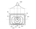
- FIG. 9 schematically shows an irradiation pattern of light in which light from the first light emitting optical system and light from the second light emitting optical system irradiated to the reflecting device are combined, and a light intensity distribution in the irradiation pattern. It is a figure which shows.
- the irradiation pattern is shown by a thick line
- the irradiation pattern is an irradiation pattern on the surface including the reflection control surface 53
- the intensity distribution is the intensity distribution on the straight line SL3.
- the region AC1 is the region having the highest light intensity, and the light intensity decreases in the order of region AC2, region AC3, region AC4, and region AC5.
- This irradiation pattern PC is a pattern in which the irradiation pattern PF and the irradiation pattern PS are combined.
- the region AC1 having the highest intensity overlaps with the center 53c of the reflection control surface 53.
- the region AC1 having the highest intensity is, for example, a region in which the intensity of light in the irradiation pattern PC is 0.9975 times or more the maximum intensity in the irradiation pattern PC.
- the irradiation pattern PC is elongated in a direction substantially parallel to the elongated direction of the reflection control surface 53, and the straight line SL3 in FIG. 9 passes through the point where the intensity of the irradiation pattern PC is highest and is elongated in the irradiation pattern PC. It is almost parallel to the direction.
- the intensity distribution in the irradiation pattern PC is a distribution having one peak.
- the half-value width PCW of the intensity distribution in the irradiation pattern PS is larger than the half-value width PFW of the intensity distribution in the irradiation pattern PF shown in FIG. 7, and smaller than the half-value width PSW of the intensity distribution in the irradiation pattern PS shown in FIG. It is said that.
- the light L1 and L2 are emitted from the first light source 31 and the second light source 41, so that the reflection device 50 is irradiated with light whose irradiation pattern on the surface including the reflection control surface 53 is the irradiation pattern PC.
- FIG. 10 is a diagram showing a high beam light distribution pattern.
- S indicates a horizontal line
- the light distribution pattern is indicated by a thick line.
- the region HA1 is the region having the highest light intensity, and the light intensity decreases in the order of the region HA2 and the region HA3.
- the region HA1 having the highest intensity is, for example, a region in which the intensity of light in the high beam light distribution pattern PH is 0.9975 times or more the maximum intensity in the light distribution pattern PH.
- the region PHA including the entire region HA1 and a part of the region HA2 is formed by the light emitted from the lamp unit 1a, and the regions other than the region PHA are emitted from the lamp unit 1b. Formed by light. That is, in the tilted state of the plurality of reflecting elements 54 of the reflecting unit 51 in the reflecting device 50 of the lamp unit 1a, the light LF emitted from the reflection control surface 53 in the first direction sets the region PHA in the high beam light distribution pattern PH. It is controlled to be the light that forms.
- the region PHA formed by the light emitted from the lamp unit 1a may overlap with the region formed by the light emitted from the lamp unit 1b.
- FIG. 11 is a diagram showing a part of the light distribution pattern of the high beam shown in FIG. 10, and is a diagram showing a region PHA formed by the light emitted from the lamp unit 1a.
- the light intensity in the region HA1 having high light intensity is not uniform
- the region HA1a is the region having the highest light intensity
- the light intensity is in the order of region HA1b, region HA1c, and region HA1d. Is lower, and the intensity in the region HA2 is lower than the intensity in the region HA1d.
- the region HA1a overlaps with the central PHAc of the region PHA, and the intensity distribution in the region PHA is a distribution having one peak, similar to the intensity distribution of the irradiation pattern PC shown in FIG. 9, and the intensity on the center side. Is high, and the strength on the outer peripheral side is low.
- at least a part of the region HA1a which is a region having high intensity in the region PHA, is emitted from the reflecting element 54 of the reflecting unit 51 which overlaps with the region AC1 which is a region having high intensity in the irradiation pattern PC shown in FIG. Formed by light.
- the region HA2 which is a region having a low intensity in the region PHA, is formed by the light emitted from the reflecting element 54 of the reflecting portion 51 which overlaps with the region AC5, which is a region having a low intensity in the irradiation pattern PC.
- a part of the high beam light distribution pattern PH is formed by the light emitted from the lamp unit 1a, and the other part is formed by the light emitted from the lamp unit 1b.
- a high beam is emitted from the headlight 1.
- the reflection device 50 forms a light distribution pattern by reflecting light by the reflection control surface 53
- the light intensity distribution in the light distribution pattern tends to be affected by the light intensity distribution in the reflection control surface 53. Since the light intensity distribution on the reflection control surface 53 depends on the light intensity distribution emitted from the light emitting optical system, the light intensity distribution in the formed light distribution pattern is influenced by the light intensity distribution emitted from the light emitting optical system. Tend to receive. Therefore, the degree of freedom of the light intensity distribution in the light distribution pattern of the emitted light may be limited.
- the vehicle headlight 1 of the present embodiment includes a first light emitting optical system 30 that emits light L1, a second light emitting optical system 40 that emits light L2, and a reflecting device 50.
- the reflection device 50 has a reflection control surface 53 composed of reflection surfaces 54r of a plurality of reflection elements 54 whose tilting states can be individually switched.
- the reflecting device 50 reflects the light L1 emitted from the first light emitting optical system 30 and the light L2 emitted from the second light emitting optical system 40 by the reflection control surface 53, and distributes light according to the tilted state of the plurality of reflecting elements 54. Form a pattern.
- the light intensity distribution in the irradiation pattern PS on the control surface 53 is different from each other.
- the vehicle headlight 1 of the present embodiment can emit light having a predetermined light distribution pattern by controlling the tilted state of the plurality of reflecting elements 54 in the reflecting device 50.
- the reflection device 50 forms a light distribution pattern by reflecting light by the reflection control surface 53
- the light intensity distribution in the formed light distribution pattern is that of the light intensity distribution on the reflection control surface 53. Tends to be affected.
- the light L1 emitted from the first light emitting optical system 30 and the light L2 emitted from the second light emitting optical system 40 are applied to the reflection control surface 53.
- the vehicle headlight 1 of the present embodiment has a degree of freedom in the distribution of light intensity on the reflection control surface 53 as compared with the case where the light emitted from one light emitting optical system is applied to the reflection control surface 53. It is possible to improve the degree of freedom of light intensity distribution in the light distribution pattern of the emitted light. Further, in the vehicle headlight 1 of the present embodiment, as described above, the light intensity distribution in the irradiation pattern PF on the reflection control surface 53 and the light intensity distribution in the irradiation pattern PS on the reflection control surface 53. Are different from each other.
- the light intensity distribution in the irradiation pattern PF on the reflection control surface 53 and the light intensity distribution in the irradiation pattern PS on the reflection control surface 53 are the same.
- the degree of freedom of the light intensity distribution on the reflection control surface 53 can be improved, and the degree of freedom of the light intensity distribution in the light distribution pattern of the emitted light can be improved.
- the maximum value FMV of the light intensity on the irradiation pattern PF on the reflection control surface 53 and the maximum value SMV of the light intensity on the irradiation pattern PS on the reflection control surface 53 are mutually exclusive. different. Therefore, in the vehicle headlight 1 of the present embodiment, the maximum value FMV of the light intensity on the irradiation pattern PF on the reflection control surface 53 and the maximum value SMV of the light intensity on the irradiation pattern PS on the reflection control surface 53. As compared with the case where the above is the same, the degree of freedom of the light intensity distribution on the reflection control surface 53 can be improved, and the degree of freedom of the light intensity distribution in the light distribution pattern of the emitted light can be improved.
- the half width PFW of the light intensity distribution in the irradiation pattern PF on the reflection control surface 53 and the half width PSW of the light intensity distribution in the irradiation pattern PS on the reflection control surface 53 Are different from each other. Therefore, the vehicle headlight 1 of the present embodiment has a half-value width PFW of the light intensity distribution on the irradiation pattern PF on the reflection control surface 53 and a half of the light intensity distribution on the irradiation pattern PS on the reflection control surface 53. Compared with the case where the price range PSW is the same, the degree of freedom of the light intensity distribution on the reflection control surface can be improved, and the degree of freedom of the light intensity distribution in the light distribution pattern of the emitted light can be improved.
- the region AF1 having the highest light intensity of the irradiation pattern PF on the reflection control surface 53 and the region AS1 having the highest light intensity of the irradiation pattern PS on the reflection control surface 53 Overlap each other. Therefore, in the vehicle headlight 1 of the present embodiment, as compared with the case where the region AF1 of the irradiation pattern PF on the reflection control surface 53 and the region AS1 of the irradiation pattern PS on the reflection control surface 53 do not overlap each other.
- the maximum value in the light intensity distribution on the reflection control surface 53 can be increased, and the maximum value in the light intensity distribution of the light distribution pattern of the emitted light can be increased.
- the maximum value FMV in the light intensity distribution of the irradiation pattern PF and the maximum value SMV in the light intensity distribution of the irradiation pattern PS are smaller than the maximum value in the light intensity distribution of the high beam light distribution pattern PH. It is especially useful in such cases.
- the first light emitting optical system 30 serves as a light collecting member that collects the light emitted from the first light source 31 and the first light source 31 and irradiates the reflection control surface 53.
- the second light emitting optical system 40 has a first reflector 32, and the second light emitting optical system 40 is a second reflector as a light collecting member that collects the light emitted from the second light source 41 and the second light source 41 and irradiates the reflection control surface 53 with the light. It has 42 and. Therefore, the vehicle headlight 1 of the present embodiment is compared with the case where the first light emitting optical system 30 does not have the first reflector 32 or the second light emitting optical system 40 does not have the second reflector 42. Therefore, the amount of light emitted to the reflection control surface 53 can be increased, and energy efficiency can be improved.
- the light collecting member in the first light emitting optical system 30 is a first reflector 32 having a reflecting surface 32r
- the light collecting member in the second light emitting optical system 40 has a reflecting surface 42r. It is said to have a second reflector 42.
- the vehicle headlight 1 of the present embodiment further includes a projection lens 60 that adjusts the divergence angle of the light LF that emits light from the reflection control surface 53 and forms a light distribution pattern according to the tilted state of the plurality of reflecting elements 54. Therefore, the vehicle headlight 1 of the present embodiment can easily set the size of the light distribution pattern of the emitted light to a desired size as compared with the case where the projection lens 60 is not provided.
- the second reference plane RP2 that is substantially parallel to the rotating shaft 54a of the reflecting element 54 and perpendicular to the reflecting surface 54r of the reflecting element 54 in the first tilted state.
- the reflection surface 32r of the first reflector 32 which is a portion for irradiating the reflection control surface 53 of the first emission optical system 30, and the reflection control surface 53 of the second emission optical system 40 are irradiated with light.
- the reflection surface 42r of the second reflector 42 which is a portion, is located.
- the arrangement of the light absorbing plate 70 can be easily designed, or the light absorbing plate 70 can be miniaturized.
- the region of the light distribution pattern of the emitted light having a high light intensity in the region PHA overlaps with the region of the irradiation pattern PC on the reflection control surface 53 having a high light intensity. It is formed by the light emitted from the reflecting element 54 of the reflecting unit 51. Further, the region where the light intensity in the region PHA is low is formed by the light emitted from the reflecting element 54 of the reflecting portion 51 which overlaps with the region where the light intensity in the irradiation pattern PC on the reflection control surface 53 is low. Therefore, the amount of light LS emitted from the reflection control surface 53 in the second direction can be reduced, and energy efficiency can be improved.
- the vehicle headlight 1 of the present embodiment is a headlight for an automobile as in the first embodiment. Further, the configuration of the vehicle headlight 1 of the present embodiment is the same as that of the vehicle headlight 1 of the first embodiment. However, in the present embodiment, the irradiation pattern PF of the light L1 from the first light emitting optical system 30 irradiated to the reflection device 50 of the lamp unit 1a is different from the irradiation pattern PF in the first embodiment, and the reflection device of the lamp unit 1a is different. The irradiation pattern PS of the light L2 from the second light emitting optical system 40 irradiated to 50 is different from the irradiation pattern PS in the first embodiment. Further, in the present embodiment, the region PHA formed by the light emitted from the lamp unit 1a in the high beam light distribution pattern PH is different from the region PHA in the first embodiment.
- FIG. 12 is a diagram showing an irradiation pattern of light from the first light emitting optical system irradiated to the reflecting device in the present embodiment and a light intensity distribution in the irradiation pattern in the same manner as in FIG.
- the intensity distribution is the intensity distribution on the straight line SL4.
- the region AF1 is the region having the highest light intensity, and the light intensity decreases in the order of region AF2, region AF3, region AF4, and region AF5.
- the irradiation pattern PF overlaps a part of the reflection control surface 53, and the region AF1 having the highest intensity is located in the reflection control surface 53.
- the region with the highest intensity in the irradiation pattern PF on the reflection control surface 53 is the region AF1. Further, when the reflection control surface 53 is viewed in a plan view, the region AF1 is located on one side of the center 53c of the reflection control surface 53, and the region AF1 and the center 53c of the reflection control surface 53 do not overlap each other. Further, the irradiation pattern PF is long in a direction substantially parallel to the long direction of the reflection control surface 53, and the straight line SL4 in FIG. 12 passes through a point having the highest intensity in the irradiation pattern PF and is long in the irradiation pattern PF. It is almost parallel to the direction. Further, the intensity distribution in the irradiation pattern PF on the reflection control surface 53 is a distribution having one peak.
- FIG. 13 is a diagram showing an irradiation pattern of light from the second light emitting optical system irradiating the reflecting device in the present embodiment and a light intensity distribution in the irradiation pattern in the same manner as in FIG.
- the intensity distribution is the intensity distribution on the straight line SL5.
- the region AS1 is the region having the highest light intensity, and the light intensity decreases in the order of region AS2, region AS3, region AS4, and region AS5.
- the irradiation pattern PS overlaps a part of the reflection control surface 53, and the region AS1 having the highest intensity is located in the reflection control surface 53.
- the region with the highest intensity in the irradiation pattern PS on the reflection control surface 53 is the region AS1.
- a part of the irradiation pattern PS and a part of the irradiation pattern PF shown in FIG. 12 overlap each other, and the other part of the irradiation pattern PS and the other part of the irradiation pattern PF are It does not overlap with each other. That is, only a part of the two irradiation patterns PF and PS overlap each other.
- the region AS1 having the highest intensity is located on the side opposite to the side where the region AF1 of the irradiation pattern PF is located with respect to the center 53c of the reflection control surface 53, and this region AS1 and the region AF1 of the irradiation pattern PF overlap each other.
- the region AF1 and the region AF5 which is the outer shape of the irradiation pattern PF are shown by broken lines.
- the irradiation pattern PS is elongated in a direction substantially parallel to the elongated direction of the reflection control surface 53, and the straight line SL5 in FIG.
- the intensity distribution in the irradiation pattern PS on the reflection control surface 53 is a distribution having one peak, similar to the intensity distribution of the irradiation pattern PF on the reflection control surface 53 shown in FIG. However, the intensity distribution in the irradiation pattern PS on the reflection control surface 53 is different from the intensity distribution in the irradiation pattern PF on the reflection control surface 53.
- the half-value width PSW of the intensity distribution in the irradiation pattern PS and the half-value width PFW of the intensity distribution in the irradiation pattern PF are different from each other, and the half-value width PSW is smaller than the half-value width PFW. Further, the maximum value SMV of the intensity in the irradiation pattern PS and the maximum value FMV of the intensity in the irradiation pattern PF are different from each other, and the maximum value SMV is smaller than the maximum value FMV.
- FIG. 14 shows an irradiation pattern of light in which the light from the first emission optical system and the light from the second emission optical system irradiated to the reflecting device in the present embodiment are combined, and the intensity distribution of the light in the irradiation pattern.
- the intensity distribution is the intensity distribution on the straight line SL6.
- the region AC1 is the region having the highest light intensity, and the light intensity decreases in the order of region AC2, region AC3, region AC4, and region AC5.
- This irradiation pattern PC is a pattern in which the irradiation pattern PF and the irradiation pattern PS are combined.
- the region AC1 having the highest intensity is located on one side of the center 53c of the reflection control surface 53, and the region AC1 and the center 53c of the reflection control surface 53 do not overlap each other. ..
- the irradiation pattern PC is elongated in a direction substantially parallel to the elongated direction of the reflection control surface 53, and the straight line SL6 in FIG. 14 passes through the point where the intensity of the irradiation pattern PC is highest and is elongated in the irradiation pattern PC. It is almost parallel to the direction. Further, the entire reflection control surface 53 is located in the irradiation pattern PC.
- each of the plurality of reflecting elements 54 is irradiated with at least one of the light L1 emitted from the first light emitting optical system 30 and the light L2 emitted from the second light emitting optical system 40.
- the intensity distribution in the irradiation pattern PC is a distribution having one peak.
- the half-value width PCW of the intensity distribution in the irradiation pattern PS is larger than the half-value width PFW of the intensity distribution in the irradiation pattern PF shown in FIG. 12, and smaller than the half-value width PSW of the intensity distribution in the irradiation pattern PS shown in FIG. It is said that.
- the light L1 and L2 are emitted from the first light source 31 and the second light source 41, so that the reflection device 50 is irradiated with light whose irradiation pattern on the surface including the reflection control surface 53 is the irradiation pattern PC.
- FIG. 15 is a diagram showing another part of the high beam light distribution pattern shown in FIG. 10, and is a diagram showing a region PHA formed by light emitted from the lamp unit 1a in the present embodiment.
- the region PHA of the present embodiment includes the entire region HA1 and a part of the region HA2, similarly to the region PHA of the first embodiment. However, the position of the region PHA is different from the position of the region PHA in the first embodiment.
- the region HA1a is located on one side of the center PHAc of the region PHA, and the region HA1a and the center of the center PHAc of the region PHA do not overlap each other.
- the intensity distribution in the region PHA is a distribution having one peak, similar to the intensity distribution of the irradiation pattern PC shown in FIG. That is, in the present embodiment, the tilted state of the plurality of reflecting elements 54 of the reflecting unit 51 in the reflecting device 50 of the lamp unit 1a is such that the light LF emitted from the reflection control surface 53 in the first direction has a high beam light distribution pattern. The light is controlled to form the above-mentioned region PHA in PH. Further, in the present embodiment, similarly to the first embodiment, the region having high intensity in the region PHA is emitted from the reflecting element 54 of the reflecting portion 51 which overlaps with the region having high intensity in the irradiation pattern PC shown in FIG.
- the region formed by light and having a low intensity in the region PHA is formed by the light emitted from the reflecting element 54 of the reflecting portion 51 that overlaps with the region having low intensity in the irradiation pattern PC.
- a part of the high beam light distribution pattern PH is formed by the light emitted from the lamp unit 1a, and the other part is formed from the lamp unit 1b. It is formed by the emitted light, and a high beam is emitted from the vehicle headlight 1.
- the vehicle headlight 1 of the present embodiment as described above, the light intensity distribution on the irradiation pattern PF on the reflection control surface 53 and the light intensity distribution on the irradiation pattern PS on the reflection control surface 53 are mutually exclusive. different. Therefore, the vehicle headlight 1 of the present embodiment can improve the degree of freedom of the light intensity distribution in the light distribution pattern of the emitted light, as in the first embodiment.
- the region AF1 having the highest light intensity of the irradiation pattern PF on the reflection control surface 53 and the region AS1 having the highest light intensity of the irradiation pattern PS on the reflection control surface 53 Do not overlap each other. Therefore, in the vehicle headlight 1 of the present embodiment, the light intensity distribution on the reflection control surface 53 is intended to be an intensity distribution having at least two peaks, or the maximum value of the light intensity distribution on the reflection control surface 53 is intended. It is possible to suppress the growth without doing so.
- the light intensity distribution in the light distribution pattern of the emitted light is set to an intensity distribution having at least two peaks, or the maximum value of the light intensity distribution in the light distribution pattern of the emitted light is unintentionally increased. Can be suppressed.
- the vehicle lighting fixture is a vehicle headlight 1 that irradiates a high beam or a low beam
- a vehicle lamp may irradiate an irradiated body such as a road surface with light that constitutes an image.
- the direction of the light emitted by the vehicle lamp and the position where the vehicle lamp is attached to the vehicle are not particularly limited. ..
- a high beam light distribution pattern is formed by the light emitted from the lamp unit 1a and the light emitted from the lamp unit 1b.
- the vehicle headlight 1 may form a predetermined light distribution pattern such as a high beam only by the light emitted from the lamp unit 1a.
- the tilted state of the plurality of reflecting elements 54 of the reflecting unit 51 in the reflecting device 50 of the lamp unit 1a is the light in which the light LF emitted from the reflection control surface 53 in the first direction forms a predetermined light distribution pattern. Is controlled to be.
- the vehicle headlight 1 as a vehicle lighting tool has two light emitting optical systems 30 and 40 that irradiate the reflection control surface 53 of the reflection device 50 with light. ..
- the vehicle lighting equipment may have a plurality of light emitting optical systems for irradiating the reflection control surface 53 of the reflecting device 50 with light, and may further have, for example, a third light emitting optical system.
- the third light emitting optical system can be configured to have a light source and a reflector that reflects the light emitted from the light source, as in the case of the first light emitting optical system 30 of the first embodiment, for example.
- Such a third light emitting optical system is arranged, for example, between the first light emitting optical system 30 and the second light emitting optical system 40. Further, when having three or more light emitting optical systems in this way, among the irradiation patterns on the reflection control surface 53 of each light emitted from each of the plurality of light emitting optical systems and irradiated on the reflection control surface 53. , The intensity distributions in at least two irradiation patterns need be different from each other.
- the entire irradiation pattern PF on the reflection control surface 53 and the entire irradiation pattern PS on the reflection control surface 53 overlap.
- the second embodiment only a part of the two irradiation patterns PF and PS on the reflection control surface 53 overlap each other. That is, in the first embodiment and the second embodiment, it can be understood that at least a part of the two irradiation patterns PF and PS on the reflection control surface 53 overlap each other. Therefore, in the vehicle headlights 1 of the first and second embodiments, there is a case where the two irradiation patterns PF and PS do not overlap even if the maximum value of the light intensity in the irradiation patterns PF and PS is not increased.
- the maximum value of the light intensity in the light distribution pattern of the emitted light can be increased.
- these vehicle headlights 1 emit light from at least one of the first light emitting optical system 30 and the second light emitting optical system 40, as compared with the case where the two irradiation patterns PF and PS do not overlap.
- the maximum value of the light intensity can be reduced, and the amount of heat emitted from the light emitting optical system can be reduced.
- the irradiation pattern PF on the reflection control surface 53 and the irradiation pattern PS on the reflection control surface 53 do not have to overlap each other.
- the entire irradiation pattern PF on the reflection control surface 53 and the irradiation pattern PS on the reflection control surface 53 may overlap with each other and a part of the other irradiation pattern.
- the irradiation pattern PF in the first embodiment may be an irradiation pattern as shown in FIG.
- FIG. 16 is a diagram showing an irradiation pattern of light from the first light emitting optical system irradiated to the reflecting device in the modified example and a light intensity distribution in the irradiation pattern in the same manner as in FIG.
- the irradiation pattern PF is located inside the outer edge of the reflection control surface 53, and the light L1 emitted from the first emission optical system 30 is Only a part of the reflection control surface 53 is irradiated.
- the entire irradiation pattern PF on the reflection control surface 53 and a part of the irradiation pattern PS on the reflection control surface 53 overlap each other. Therefore, a light distribution pattern is formed in which the light intensity on the outer edge side of the light distribution pattern is lower than the light intensity on the central side, as in the region PHA of the high beam light distribution pattern PH shown in FIGS. 11 and 15. Can be easier.
- the region AS5 which is the outer shape of the irradiation pattern PS is shown by a broken line.
- the half-value width PFW of the intensity distribution in the irradiation pattern PF on the reflection control surface 53 and the half-value width PSW of the intensity distribution in the irradiation pattern PS on the reflection control surface 53 are different. ..
- the full width at half maximum PFW and the full width at half maximum PSW may be the same.
- the maximum value FMV of the intensity on the irradiation pattern PF on the reflection control surface 53 and the maximum value SMV of the intensity on the irradiation pattern PS on the reflection control surface 53 may be the same.
- the condensing members of the first light emitting optical system 30 and the second light emitting optical system 40 are reflectors 32 and 42.
- the condensing member only needs to be able to condense the light emitted from the light source and irradiate the reflection control surface 53.
- a lens may be used as the condensing member.
- the condensing member in the first light emitting optical system 30 and the condensing member in the second light emitting optical system 40 may be different.
- the condensing member in one light emitting optical system is used as a reflector and the other light emitting optical.
- the condensing member in the system may be a lens.
- the first light emitting optical system 30 and the second light emitting optical system 40 have light sources 31 and 41 and reflectors 32 and 42 as condensing members, but the light source 31 , 41 may be the only component.
- the reflecting surfaces 32r and 42r of the reflectors 32 and 42 as the light collecting member are based on a rotating elliptic curved surface.
- the reflecting surfaces 32r and 42r need only be able to collect the light from the light sources 31 and 41 and irradiate the reflection control surface 53 of the reflecting device 50 from a free curved surface based on a parabola that opens toward the reflecting device 50 side. It may have a concave shape.
- the light emitting unit 20 includes a projection lens 60 composed of one lens.
- the projection lens 60 included in the light emitting unit 20 may be a lens group including a plurality of lenses arranged in parallel in the propagation direction of the light emitted from the reflecting device 50, and the plurality of parallel lenses may be a convex lens.
- a plurality of types of lenses such as a concave lens and a free curved lens may be included.
- the light emitting unit 20 does not have to include the projection lens 60.
- the light sources 31 and 41 are surface mount type LEDs.
- the light source is not particularly limited, and for example, the light source may be a laser element that emits laser light.
- the irradiation pattern on the reflection control surface 53 of the light emitted from the light emitting optical system having the light source and irradiated on the reflection control surface 53 is different from the case where the LED is used as the light source. It may be easy to reduce the half-value width of the intensity distribution and increase the maximum value of this intensity distribution.
- FIG. 17 is a diagram showing the lamp unit 1a of the present embodiment in the same manner as in FIG. 2, and FIG. 18 is a diagram showing the light emitting unit 20 shown in FIG. 17 in the same manner as in FIG.
- FIG. 19 is a side view schematically showing the light emitting unit 20 shown in FIG.
- the positional relationship between the first light emitting optical system 30 and the second light emitting optical system 40 in the left-right direction reverses the positional relationship in the first embodiment. It is in a positional relationship.
- the shapes of the first reflector 32 and the second reflector 42 are different from the shapes in the first embodiment. In FIG. 19, the description of the first light emitting optical system 30 is omitted.
- the optical axis 31a of the first light source 31 is on the front side and the second light source 41 side of the second light emitting optical system 40. Arranged to extend to.
- the optical axis 31a passes through the center of the first light source 31 and is perpendicular to the exit surface of the first light source 31.
- the optical axis 31a is substantially perpendicular to the portion of the circuit board on which the first light source 31 is mounted. In the present embodiment, the optical axis 31a of the first light source 31 is tilted downward.
- the first reflector 32 is a curved plate-shaped member, and is arranged so as to cover the first light source 31 from the front side and the lower side.
- the reflection surface 32r is curved so as to be concave on the side opposite to the first light source 31 side, and for example, the light emitted from the first light source 31 is collected and irradiated to the reflection control surface based on the rotating elliptic curved surface. It is composed.
- Most of the reflecting surface 32r is inclined so as to approach the reflecting device 50 located on the rear side from the first light source 31 side toward the second light source 41 side. Further, as shown in FIG. 17, the first light source 31 and the first reflector 32 overlap each other when the horizontal plane is viewed in a plan view.
- the optical axis 41a of the second light source 41 extends to the front side and the first light source 31 side. Arranged to do. Therefore, as shown in FIG. 17, when the horizontal plane is viewed in a plan view, the optical axis 31a of the first light source 31 and the optical axis 41a of the second light source 41 intersect.
- the optical axis 41a of the second light source 41 passes through the center of the second light source 41 and is perpendicular to the exit surface of the second light source 41, similarly to the optical axis 31a of the first light source 31.
- the optical axis 41a is substantially perpendicular to the portion of the circuit board on which the second light source 41 is mounted.
- the optical axis 41a of the second light source 41 is tilted downward like the optical axis 31a of the first light source 31.
- the second reflector 42 is a curved plate-shaped member, and is arranged so as to cover the second light source 41 from the front side and the lower side.
- the reflection surface 42r is curved so as to be concave on the side opposite to the second light source 41 side, and for example, the light emitted from the second light source 41 is collected and irradiated to the reflection control surface based on the rotating elliptic curved surface. It is composed.
- Most of the reflecting surface 42r is inclined so as to approach the reflecting device 50 located on the rear side from the second light source 41 side toward the first light source 31 side. Further, as shown in FIG. 17, when the horizontal plane is viewed in a plan view, the second light source 41 and the second reflector 42 overlap each other.
- the end of the second reflector 42 on the first reflector 32 side and the end of the first reflector 32 on the second reflector 42 side are joined to each other to form the first reflector 32 and the second reflector 42. It is formed integrally.
- the first reflector 32 and the second reflector 42 may be formed separately.
- the reflection device 50 of the present embodiment is arranged so that the reflection control surface 53 is substantially parallel to the vertical direction and extends in the left-right direction and is located behind the first light source 31 and the second light source 41.
- the extending direction of the rotating shafts 54a of the plurality of reflecting elements 54 is substantially parallel to the left-right direction.
- FIG. 17 shows the first light source 31 and the second light source. It can be understood that it is a view in which a plane passing through 41 and perpendicular to the reflection control plane 53 is viewed in a plane. Further, as shown in FIG.
- the reflection control surface 53 of the reflection device 50 is a first light source when a surface perpendicular to the reflection control surface 53 is viewed in a plan view through the first light source 31 and the second light source 41. It is located closer to the second light source 41 than 31 and closer to the first light source 31 than the second light source 41. Further, as shown in FIG. 19, the reflection control surface 53 of the reflection device 50 is located above the first light source 31 and the second light source 41 and behind the first reflector 32 and the second reflector 42. There is.
- the first light emitting optical system 30 is located on one side of the first reference plane (not shown) that passes through the center 53c of the reflection control surface 53 and extends in the front-rear direction and the vertical direction, and the first reference plane is used.
- the second light emitting optical system 40 is located on the other side with respect to the plane. Therefore, the reflection surface 32r of the first reflector 32, which is a portion for irradiating the reflection control surface 53 of the first light emitting optical system 30 with light, is located on one side with respect to the first reference plane. Further, the reflection surface 42r of the second reflector 42, which is a portion of irradiating the reflection control surface 53 of the second light emitting optical system 40 with light, is located on the other side with respect to the first reference plane.
- the first reference plane of the present embodiment is substantially perpendicular to the rotating shaft 54a. ..
- the projection lens 60 of the present embodiment has the first reflector 32 and the first reflector 32 and the first reflector 32 when the plane perpendicular to the reflection control surface 53 is viewed in a plane through the first light source 31 and the second light source 41. 2 It is arranged on the side opposite to the reflection control surface 53 side of the reflector 42.
- the lower part of the projection lens 60 is cut out. Specifically, as shown in FIG. 19, a flat surface RP that passes through the lower part of the projection lens 60 and tilts away from the optical axis 60a of the projection lens 60 as it goes from the entrance surface 60i side of the projection lens 60 to the exit surface 60o side. As a reference, the side of the projection lens 60 opposite to the optical axis 60a side of the projection lens 60 is cut out. Therefore, the bottom surface 60b formed on the projection lens 60 by cutting out the projection lens 60 as described above is located on the plane RP, and the projection lens 60 moves from the incident surface 60i side toward the exit surface 60o side. Tilt away from the optical axis 60a.
- the surface used as a reference when the projection lens 60 is cut out is tilted away from the optical axis 60a of the projection lens 60 as it passes through the projection lens 60 and moves from the incident surface 60i side of the projection lens 60 to the exit surface 60o side. As long as it is, it may be a curved surface.
- FIG. 20 is a front view schematically showing the projection lens shown in FIG. 17, and is a view of the incident surface side of the projection lens viewed from a direction along the optical axis of the projection lens. Note that FIG. 20 also shows a part of the first reflector 32 and the second reflector 42. As shown in FIG. 20, a part of the incident surface 60i of the projection lens 60, a part of the first reflector 32, and a part of the second reflector 42 overlap each other in the direction along the optical axis 60a of the projection lens 60. ing.
- the incident surface 60i side of the projection lens 60 when the incident surface 60i side of the projection lens 60 is viewed from the direction along the optical axis 60a of the projection lens 60, a part of the bottom surface 60b is covered with the first reflector 32, and another part of the bottom surface 60b. Is covered by the second reflector 42, and the bottom surface 60b is not exposed.
- the high beam light distribution pattern shown in FIG. 10 is formed by the light emitted from the lamp unit 1a and the light emitted from the lamp unit 1b.
- each of the light L1 emitted from the first emission optical system 30 and the light L2 emitted from the second emission optical system 40 irradiates the entire surface of the reflection control surface 53. Will be done.
- the irradiation pattern PF of the light L1 irradiated on the surface including the reflection control surface 53 and the irradiation pattern PS of the light L2 irradiated on the surface including the reflection control surface 53 are not particularly limited.
- a vehicle lamp may irradiate a wide area in front of the vehicle, draw a large image on the road surface, or increase the intensity of the irradiating light, and may require a large amount of light. .. Therefore, for example, in a vehicle lamp as in Patent Document 1, it is conceivable to irradiate the reflection control surface of the reflection device with light emitted from a plurality of light sources. In these light sources, the luminous efficiency tends to decrease or the life tends to decrease due to heat generated during light emission. If the distance between these light sources is short, the light sources may overheat each other due to the heat generated by these light sources.
- the distance between these light sources becomes long to disperse the heat generated by each light source.
- the propagation direction of the light emitted from one light source and incident on the reflection control surface and the other light source are compared with the case where the distance between the two light sources is not long.
- the angle between the light emitted and the light propagating on the reflection control surface tends to be large.
- the angle between the propagation direction of the light from one light source reflected by the reflection control surface and emitted from the reflection device and the propagation direction of the light from the other light source reflected by the reflection control surface and emitted from the reflection device is also large. It tends to be. For this reason, it becomes difficult for the light emitted from the reflecting device to propagate in a desired direction, and the amount of light emitted from the reflecting device to form a predetermined light distribution pattern may decrease and the light distribution pattern may become dark. ..
- the vehicle headlight 1 of the present embodiment emits from the first light source 31, the first reflector 32 that reflects the light L1 emitted from the first light source 31, the second light source 41, and the second light source 41.
- a second reflector 42 that reflects the light L2 and a reflecting device 50 are provided.
- the reflection device 50 has a reflection control surface 53 that reflects light L1 emitted from the first light source 31 and reflected by the first reflector 32 and light L2 emitted from the second light source 41 and reflected by the second reflector 42.
- a predetermined light distribution pattern is formed by the light reflected by the reflection control surface 53.
- At least a part of the reflection surface 32r of the first reflector 32 is a reflection control surface 53 of the reflection device 50 as it goes from the first light source 31 side to the second light source 41 side. It is said to be a surface that tilts toward.
- At least a part of the reflection surface 42r of the second reflector 42 is a surface that inclines so as to approach the reflection control surface 53 of the reflection device 50 from the second light source 41 side toward the first light source 31 side.
- the propagation direction of the light L1 emitted from the first light source 31 and reflected by the reflecting surface 32r of the first reflector 32 is the second light source. It is possible to approach the direction parallel to the propagation direction of the light L2 emitted from the 41 and reflected by the reflecting surface 42r of the second reflector 42.
- the vehicle headlight 1 of the present embodiment can suppress the overheating of the first light source 31 and the second light source 41 and suppress the darkening of the light distribution pattern of the emitted light.
- the vehicle headlight 1 of the present embodiment further includes a projection lens 60 that adjusts the divergence angle of the light LF that is emitted from the reflection device 50 and forms a predetermined light distribution pattern. Therefore, the vehicle headlight 1 of the present embodiment can easily set the size of the light distribution pattern of the emitted light to a desired size as compared with the case where the projection lens 60 is not provided.
- the parts and the parts overlap each other. Therefore, the light LF emitted from the reflection control surface 53 is different from the case where the first reflector 32 and the second reflector 42 and the incident surface 60i of the projection lens 60 do not overlap in the direction along the optical axis 60a of the projection lens 60. It is possible to suppress the passage through the gap between the incident surface 60i of the projection lens 60 and the first reflector 32 and the gap between the incident surface 60i of the projection lens 60 and the second reflector 42.
- the vehicle headlight 1 of the present embodiment can suppress the emission of light in an unintended direction as compared with the above case. From the viewpoint of suppressing the emission of light in an unintended direction, at least one part of the first reflector 32 and the second reflector 42 and the projection lens 60 in the direction along the optical axis 60a of the projection lens 60. It suffices if a part of the incident surface 60i of the above overlaps with each other.
- the vehicle headlight 1 of the present embodiment with reference to a plane RP that is tilted away from the optical axis 60a of the projection lens 60 as it passes through the projection lens 60 and moves from the incident surface 60i side of the projection lens 60 toward the exit surface 60o side. , The side of the projection lens 60 opposite to the optical axis 60a side of the projection lens 60 is cut out. Therefore, the member can be arranged in the space formed by cutting out the projection lens 60, and the vehicle headlight can be miniaturized. Further, the bottom surface 60b formed on the projection lens 60 by cutting out the projection lens 60 is tilted from the incident surface 60i side toward the exit surface 60o side so as to be separated from the optical axis 60a of the projection lens 60.
- the projection lens 60 when the bottom surface 60b formed on the projection lens 60 by cutting out the projection lens 60 is parallel to the optical axis 60a of the projection lens 60, or from the entrance surface 60i side toward the emission surface 60o side, the projection lens 60 The light incident on the projection lens 60 can be suppressed from being reflected by the bottom surface 60b, and the light emitted in an unintended direction can be suppressed as compared with the case where the light is tilted toward the optical axis 60a.
- the vehicle headlight 1 of the present embodiment when the surface perpendicular to the reflection control surface 53 is viewed in a plan view through the first light source 31 and the second light source 41, the first light source 31 and the first reflector 32 Overlap each other, and the second light source 41 and the second reflector 42 overlap each other.
- the divergence angle of the light emitted from the light source is about 180 degrees. Therefore, in the case of plan view as described above, the amount of light emitted from the first light source 31 and not reflected by the first reflector 32 is compared with the case where the first light source 31 and the first reflector 32 do not overlap each other. Can be reduced.
- the amount of light emitted from the second light source 41 and not reflected by the second reflector 42 is reduced as compared with the case where the second light source 41 and the second reflector 42 do not overlap each other. It can be reduced. Therefore, in the vehicle headlight 1 of the present embodiment, it is possible to suppress the emission of light in an unintended direction as compared with these cases. From the viewpoint of suppressing the emission of light in an unintended direction, at least one of the first light source 31 and the second light source 41 should overlap with the corresponding reflector in the above-mentioned plan view. Just do it.
- the reflection control surface 53 of the reflection device 50 is composed of the reflection surfaces 54r of a plurality of reflection elements 54 whose tilting states can be individually switched. Therefore, the light distribution pattern of the emitted light can be changed by controlling the tilted state of the plurality of reflecting elements 54.
- the second aspect of the present invention has been described by taking the third embodiment as an example, the second aspect of the present invention is not limited to this.
- the vehicle lighting fixture is the vehicle headlight 1 that irradiates a high beam or a low beam
- the second aspect of the present invention is not particularly limited.
- a vehicle lamp may irradiate an irradiated body such as a road surface with light that constitutes an image.
- the direction of the light emitted by the vehicle lamp and the position where the vehicle lamp is attached to the vehicle are not particularly limited. ..
- a high beam light distribution pattern is formed by the light emitted from the lamp unit 1a and the light emitted from the lamp unit 1b.
- the vehicle headlight 1 may form a predetermined light distribution pattern such as a high beam only by the light emitted from the lamp unit 1a.
- the tilted state of the plurality of reflecting elements 54 of the reflecting unit 51 in the reflecting device 50 of the lamp unit 1a is the light in which the light LF emitted from the reflection control surface 53 in the first direction forms a predetermined light distribution pattern. Is controlled to be.
- the vehicle headlight 1 as a vehicle lighting tool has two light emitting optical systems 30 and 40 that irradiate the reflection control surface 53 of the reflection device 50 with light.
- the vehicle lamp may have yet another light emitting optical system together with the two light emitting optical systems 30 and 40, and may further have, for example, a third light emitting optical system.
- the configuration of the third light emitting optical system is not particularly limited.
- the configuration of the third light emitting optical system may be a configuration having a light source and a reflector for reflecting the light emitted from the light source, as in the case of the first light emitting optical system 30 of the third embodiment, and emits light from the light source and the light source.
- It may have a configuration including a lens that collects light and irradiates the reflection control surface 53, or may have a configuration consisting of only a light source.
- a third light emitting optical system is arranged, for example, between the first light emitting optical system 30 and the second light emitting optical system 40.
- the first light emitting optical system 30 and the second light emitting optical system 40 are arranged in parallel in the left-right direction, and have a symmetrical configuration.
- the first light emitting optical system 30 and the second light emitting optical system 40 may have an asymmetrical configuration, or may be arranged in parallel in the vertical direction.
- the reflection surface 32r of the first reflector 32 is formed in a curved surface shape so as to collect the light emitted from the first light source 31 and irradiate the reflection control surface 53.
- the reflection surface 32r of the first reflector 32 may be a surface that inclines so as to approach the reflection control surface 53 from the first light source 31 side toward the second light source 41 side, and the entire reflection surface 32r. May be formed in a flat shape.
- the reflection surface 42r of the second reflector 42 is formed in a curved surface shape so as to collect the light emitted from the second light source 41 and irradiate the reflection control surface 53.
- at least a part of the reflection surface 42r of the second reflector 42 may be a surface that is inclined so as to approach the reflection control surface 53 from the second light source 41 side toward the first light source 31 side, and the entire reflection surface 42r. May be formed in a flat shape.
- the light L1 emitted from the first light source 31 and reflected by the first reflector 32 and the light L2 emitted from the second light source 41 and reflected by the second reflector 42 are each a reflection control surface.
- the entire surface of 53 was irradiated.
- these lights L1 and L2 may be applied to the reflection control surface 53, and may be applied to only a part of the reflection control surface 53.
- the reflection device 50 is a so-called DMD having a reflection control surface 53 composed of reflection surfaces 54r of a plurality of reflection elements 54 whose tilting states can be individually switched.
- the reflecting device has a reflecting surface that reflects the light L1 emitted from the first light source 31 and reflected by the first reflector 32 and the light L2 emitted from the second light source 41 and reflected by the second reflector 42.
- a predetermined light distribution pattern may be formed by the light reflected by the reflecting surface. Examples of such a reflecting device include LCOS (Liquid Crystal On Silicon), which is a reflective liquid crystal panel.
- the LCOS includes a silicon substrate in which a plurality of electrodes whose potentials are independently controlled are arranged in a matrix on the surface, a transparent electrode, and a liquid crystal layer sandwiched between the electrodes and the transparent electrodes.
- the potentials of the plurality of electrodes are independently controlled, so that the refractive index of the liquid crystal layer sandwiched between each electrode and the transparent electrode changes independently. Therefore, the light incident from the transparent electrode side, reflected by the electrode, and emitted from the transparent electrode side passes through the liquid crystal layer having a refractive index corresponding to the potential of the electrode.
- the phase of the light incident on the LCOS is adjusted for each portion corresponding to each electrode, and the light having a modulated phase distribution is emitted from the LCOS. Since light having different phases interferes with each other and is diffracted, LCOS diffracts incident light according to a pattern consisting of the refractive index of the liquid crystal layer corresponding to each electrode, and a light distribution pattern based on this refractive index pattern. Light is emitted. As described above, in LCOS, light incident from the transparent electrode side is reflected by the electrode and emitted from the transparent electrode side, and a light distribution pattern is formed by the light emitted from the transparent electrode side. Therefore, in LCOS, it can be understood that the surface of the electrode on the transparent electrode side is a reflective surface that reflects light, and the light distribution pattern is formed by the light reflected by the surface of the electrode on the transparent electrode side.
- the first light source 31 and the second light source 41 are surface mount type LEDs.
- the optical axis 31a of the first light source 31 and the optical axis 41a of the second light source 41 intersect.
- the type of light source is not particularly limited as long as it is present.
- the first light source 31 and the second light source 41 may be laser elements that emit laser light, and the first light source 31 and the second light source 41 may be different types of light emitting elements.
- FIG. 21 is a diagram showing a vehicle headlight according to the present embodiment, and is a diagram schematically showing a cross section of the vehicle headlight in the vertical direction.
- the vehicle headlight 1 of the present embodiment is intended for automobiles as in the first embodiment, and a pair of vehicle headlights 1 are provided in front of the vehicle. In the present embodiment, one of the vehicle headlights 1 will be described. Unlike the vehicle headlight 1 of the first embodiment, the vehicle headlight 1 of the present embodiment is composed of one lamp unit.
- the light emitting unit 20 of the vehicle headlight 1 in the present embodiment includes the first light emitting optical system 30 and the second light emitting optical system 40 in the light emitting unit 20 of the first embodiment.
- the light source 131 and the projection optical system 160 are provided in place of the projection lens 60.
- the light source 131 of the present embodiment is an LED that emits white light, and is arranged so as to emit light to the rear side.
- the reflection device 50 of the present embodiment is arranged so that the reflection control surface 53 is irradiated with the light from the light source 131 and the light emitted from the reflection control surface 53 in the first direction is incident on the projection optical system 160. Will be done.
- the reflection device 50 of the present embodiment is arranged so that the reflection control surface 53 is substantially parallel to the vertical direction and extends in the left-right direction and is located behind the light source 131.
- the extending direction of the rotating shafts 54a of the plurality of reflecting elements 54 is substantially parallel to the left-right direction.
- the light source 131 is arranged below the reflection control surface 53 of the reflection device 50 so that the first direction described above is substantially parallel to the horizontal direction and is directed forward. ..
- the reflection control surface 53 reflects the irradiated light to emit light having a predetermined light distribution pattern toward the first direction. Therefore, it can be understood that the reflection control surface 53 also serves as an incident surface on which light is incident and an exit surface on which light is emitted.
- the light distribution pattern formed by the light emitted from the reflection control surface 53 in the first direction is the reflection control surface 53 from a direction parallel to the first direction, which is the propagation direction of the light forming the light distribution pattern. Is projected on the reflection control surface 53 when viewing.
- the reflection control surface 53 is composed of reflection surfaces 54r of a plurality of reflection elements 54 arranged two-dimensionally and has a planar shape, and the reflection control surface 53 is irradiated with light emitted from a light source 131. Therefore, it can be understood that the reflecting device 50 is a light distribution pattern forming unit in which the light emitted from the light source 131 is incident on the flat incident surface and emits the light of a predetermined light distribution pattern from the flat emitting surface.
- the projection optical system 160 of this embodiment is composed of a lens 161.
- the lens 161 is a lens in which the entrance surface 161i and the exit surface 161o are formed in a convex shape.
- the lens 161 is arranged in front of the reflection device 50, and light emitted from the reflection control surface 53 in the first direction passes through the lens 161.
- the enlargement ratio of the outer peripheral region in the predetermined light distribution pattern formed by the light emitted from the reflection control surface 53 in the first direction is larger than the enlargement ratio of the central region.
- the predetermined light distribution pattern is enlarged and projected.
- the propagation of light in the projection optical system 160 composed of the lens 161 will be described with reference to FIG. 22.
- FIG. 22 is a diagram for explaining the propagation of light in the projection optical system.
- the optical axis of the projection optical system 160 of the present embodiment is the optical axis 161a of the lens 161 and the main point when the projection optical system 160 is approximated by a thin lens is the main point 161 pp when the lens 161 is approximated by a thin lens.
- the focal point on the reflecting device 50 side of the projection optical system 160 is the focal point 161f on the incident surface 161i side of the lens 161
- the focal surface on the reflecting device 50 side of the projection optical system 160 is the focal surface 161fp on the incident surface 161i side of the lens 161. is there.
- the focal plane 161 fp is generally flat.
- the first reference point P1, the second reference point P2, and the third reference point P3 shown in FIG. 22 are located on the focal plane 161 fp, respectively. Then, the distance between the focal point 161f and the first reference point P1 is r1, the distance between the focal point 161f and the second reference point P2 is r2, the distance between the focal point 161f and the third reference point P3 is r3, and the first reference is made.
- ⁇ 1 be the tilt angle of the light LP1 passing through the point P1 and the principal point 161 pp with respect to the optical axis 161a in the exit direction from the lens 161 and the light in the emission direction of the light LP2 passing through the second reference point P2 and the principal point 161 pp.
- the tilt angle with respect to the axis 161a is ⁇ 2 and the tilt angle of the optical LP3 passing through the third reference point P3 and the principal point 161pp with respect to the optical axis 161a in the emission direction from the lens 161 is ⁇ 3, the following equations (1) and (1) 2) holds. That is, the lens 161 is formed so that the above equations (1) and (2) are satisfied.
- the second reference point P2 has a tilt angle ⁇ 2 with respect to the optical axis 161a in the emission direction from the lens 161 of the optical LP2 passing through the second reference point P2 and the principal point 161 pp. ) And the reference point that is the same as the angle ⁇ 2 when the following equation (3) holds. Therefore, the inclination angle ⁇ 1 is smaller than the angle ⁇ 1 when the above equations (1) and (3) are satisfied, and the inclination angle ⁇ 3 is the angle ⁇ 3 when the above equations (1) and (3) are satisfied. Will be greater than.
- the light source image is arranged on or near the focal plane 161 fp, so that the entire light source image is enlarged and inverted at a constant magnification.
- the image is formed at infinity and the like.
- the above equations (1) and (2) are established. Therefore, by arranging the light source image on or near the focal plane 161 fp, the light source image is enlarged and the inverted image is formed at infinity or the like.
- the entire light source image is not enlarged at a constant magnification, but the enlargement ratio of the region opposite to the optical axis 161a side in the light source image is larger than the enlargement ratio of the region on the optical axis 161a side. Is also enlarged to be larger. That is, in the light source image, the enlargement ratio of the region near the optical axis 161a is smaller than the enlargement ratio of the region farther from the optical axis 161a than this region.
- the lens 161 is arranged so that the focal point 161f is located on or near the reflection control surface 53 and the optical axis 161a extends in the front-rear direction substantially parallel to the horizontal direction. Therefore, the focal plane 161 fp extends along the reflection control plane 53.
- the optical axis 161a of the lens 161 passes through the central portion of the image on the reflection control surface 53 of the light emitted from the reflection control surface 53 in the first direction and incident on the lens 161.
- a predetermined light distribution pattern is formed by the light emitted from the reflection control surface 53 in the first direction, and the light is incident on the lens 161. Therefore, the light is emitted from the reflection control surface 53 in the first direction and incident on the lens 161.
- the image on the light reflection control surface 53 is a predetermined light distribution pattern. Therefore, by arranging the lens 161 as described above, the magnification of the outer peripheral region in the predetermined light distribution pattern formed by the light emitted from the reflection control surface 53 in the first direction is increased.
- the predetermined light distribution pattern can be enlarged and projected so as to be larger than the enlargement ratio of the region on the central side.
- the optical axis 161a of the lens 161 passes through the center of the reflection control surface 53 and is substantially perpendicular to the reflection control surface 53.
- the operation of the vehicle headlight 1 will be described. Specifically, the operation of emitting a high beam will be described.
- the light L11 emitted from the light source 131 irradiates the reflection control surface 53 of the reflection device 50.
- the light L11 is applied to the entire surface of the reflection control surface 53.
- FIG. 23 is a diagram schematically showing an irradiation pattern of light irradiated to the reflection device 50 as a light distribution pattern forming unit, and schematically shows an irradiation pattern of the light on a surface including a reflection control surface 53. It is a figure. In FIG. 23, the irradiation pattern is shown by a thick line.
- the surface including the reflection control surface 53 here means reflection when, for example, the tilted state of the plurality of reflecting elements 54 is a state in which the reflecting surfaces 54r of the plurality of reflecting elements 54 are located on the same plane. It is a flat surface including the control surface 53.
- the region AF1 is the region with the highest intensity, and the intensity decreases in the order of region AF2, region AF3, and region AF4.
- the center 53c of the reflection control surface 53 is located in the region AF1 having the highest intensity.
- the region AF1 is located substantially in the center of the irradiation pattern PF
- the region AF2 surrounds the periphery of the region AF1
- the region AF3 surrounds the periphery of the region AF2
- the region AF4 surrounds the periphery of the region AF3. Therefore, it can be understood that the light intensity distribution on the reflection control surface 53 is such that the light intensity on the central side of the reflection control surface 53 is higher than the light intensity on the outer peripheral side.
- the light L11 incident on the reflection control surface 53 is reflected by the reflection control surface 53.
- a plurality of reflections are made so that the light LF emitted from the reflection control surface 53 in the first direction passes through the lens 161 to form the high beam light distribution pattern PH shown in FIG.
- the tilted state of the element 54 is controlled.
- the enlargement ratio of the outer peripheral region in the predetermined light distribution pattern formed by the light LF emitted from the reflection control surface 53 in the first direction is larger than the enlargement ratio of the central region. It is configured to magnify and project the predetermined light distribution pattern so as to be large.
- the light distribution pattern of the light LF emitted from the reflection control surface 53 in the first direction changes as the light LF passes through the lens 161. Therefore, the light distribution pattern of the light LF emitted from the reflection control surface 53 in the first direction is a light distribution pattern in consideration of this change.
- the light distribution pattern of the light LF emitted from the reflection control surface 53 in the first direction is changed by the lens 161 to become a high beam light distribution pattern PH.
- the light LF forming the high beam light distribution pattern PH is emitted toward the outside of the vehicle headlight 1 via the front cover 12. In this way, the light of the high beam light distribution pattern PH is emitted from the vehicle headlight 1.
- Most of the light LS emitted from the reflection control surface 53 in the second direction is incident on the light absorption plate 70 and converted into heat.
- FIG. 24 is a diagram schematically showing an image on the reflection control surface of light emitted from the reflection control surface and incident on the lens.
- the image 53i is shown by a thick line.
- the region 53A1 is the region having the highest light intensity, and the light intensity decreases in the order of the region 53A2, the region 53A3, and the region 53A4.
- the light emitted from the reflection control surface 53 and incident on the lens 161 is the light LF emitted from the reflection control surface 53 in the first direction. Therefore, the image 53i is a light distribution pattern formed by the light LF emitted from the reflection control surface 53 in the first direction.
- the image 53i corresponds to the high beam light distribution pattern PH, it is an image in consideration of the influence of the magnifying action of the lens 161.
- the region 53A1 in the image 53i generally corresponds to the region HA1 of the high beam light distribution pattern PH shown in FIG.
- the region 53A2 roughly corresponds to the region HA2
- the region 53A3 roughly corresponds to the region HA3
- the region 53A4 roughly corresponds to the region HA4.
- the outer edge of the image 53i is separated from the outer edge 53e of the reflection control surface 53. Therefore, the reflecting element 54 located between the outer edge of the image 53i and the outer edge 53e of the reflection control surface 53 emits the light L11 from the light source 131 in the second direction.
- the light intensity distribution in the light distribution pattern tends to be affected by the light intensity distribution on the incident surface on which the light is incident. ..
- the light intensity on the central side of the light distribution pattern tends to be higher than the light intensity on the outer peripheral side. Therefore, in the above-mentioned optical elements in vehicle headlights, the light intensity distribution on the incident surface is such that the light intensity on the central side of the incident surface is higher than the light intensity on the outer peripheral side. Tends to be. Therefore, there is a concern that heat will be concentrated on the central portion of the incident surface of the optical element irradiated with light and the life of the optical element will be shortened.
- the vehicle headlight 1 of the present embodiment is a projection optical system composed of a light source 131, a reflection device 50 as a light distribution pattern forming unit, and a lens 161 to magnify and project a predetermined light distribution pattern. 160 and.
- the reflection device 50 the light L1 emitted from the light source 131 is incident on the planar reflection control surface 53, and the light of a predetermined light distribution pattern is emitted from the reflection control surface 53.
- the projection optical system 160 enlarges and projects the predetermined light distribution pattern so that the enlargement ratio of the outer peripheral region in the predetermined light distribution pattern is larger than the enlargement ratio of the central region.
- the light intensity on the central side of the light distribution pattern tends to be higher than the light intensity on the outer peripheral side.
- the enlargement ratio of the outer peripheral region in the predetermined light distribution pattern formed by the reflector 50 is the enlargement of the central region.
- a predetermined light distribution pattern is enlarged and projected so as to be larger than the rate. Therefore, in the light distribution pattern projected by the vehicle headlight 1 of the present embodiment, the predetermined light distribution pattern formed by the reflecting device 50 is expanded and the region on the outer peripheral side of the predetermined light distribution pattern is expanded. The light distribution pattern is such that the extension of the region on the central side is suppressed.
- the vehicle headlight 1 of the present embodiment can reduce the intensity of light on the central side of the reflection control surface 53, which is the incident surface on which the light of the reflection device 50 is incident, and the central portion of the reflection control surface 53. Durability can be improved by suppressing the concentration of heat on the surface.
- the above formula (1) and the above formula (2) hold.
- Such a projection optical system 160 is arranged so that the optical axis 161a of the projection optical system 160 passes through the central portion of the light source image and the light source image is located on the focal plane 161fp of the projection optical system 160.
- An image in which the light source image is enlarged can be imaged at infinity or the like so that the magnification of the outer peripheral region in this light source image is larger than the magnification of the central region. Therefore, in the vehicle headlight 1 of the present embodiment, the enlargement ratio of the outer peripheral region in the predetermined light distribution pattern formed by the reflector 50 is larger than the enlargement ratio of the central region.
- a light distribution pattern in which the light distribution pattern of the above is enlarged can be imaged at infinity or the like.
- the second reference point P2 has an inclination angle ⁇ 2 with respect to the optical axis 161a in the emission direction from the projection optical system 160 of the optical LP2 passing through the second reference point P2 and the principal point 161 pp. Is a reference point that is the same as the angle ⁇ 2 when the above equations (1) and (3) are satisfied. That is, the lens 161 of the projection optical system 160 is formed so that the second reference point P2 becomes such a reference point.
- a light distribution pattern in which the entire predetermined light distribution pattern formed by the reflector 50 is enlarged at a constant magnification can be imaged at infinity or the like.
- the angle ⁇ 1 is smaller and the angle ⁇ 3 is larger than in this case. Therefore, in the vehicle headlight 1 of the present embodiment, the extension of the central region in the projected light distribution pattern is suppressed as compared with the above case, and the central side of the reflection control surface 53 of the reflection device 50 is suppressed. The intensity of the light in the above can be lowered, and the concentration of heat on the central portion of the reflection control surface 53 can be suppressed to improve the durability.
- the reflection device 50 has a planar reflection control surface 53 composed of reflection surfaces 54r of a plurality of reflection elements 54 whose tilting states can be individually switched.
- the light L11 emitted from the light source 131 is reflected by the reflection control surface 53 to emit light having a predetermined light distribution pattern.
- the reflection control surface 53 also serves as an incident surface on which the light L11 emitted from the light source 131 is incident and an emitting surface that emits light having a predetermined light distribution pattern. Therefore, the light distribution pattern of the emitted light can be changed by controlling the tilted state of the plurality of reflecting elements 54.
- the outer edge of the image 53i on the reflection control surface 53 of the light LF emitted from the reflection control surface 53 and incident on the projection optical system 160 is the outer edge 53e of the reflection control surface 53. It is separated.
- light having a predetermined light distribution pattern is emitted from the reflection control surface 53 of the reflection device 50, and this light is incident on the projection optical system 160. Therefore, the image 53i on the reflection control surface 53 of the light LF incident on the projection optical system 160 has a predetermined light distribution pattern.
- the outer edge of the image 53i is separated from the outer edge 53e of the reflection control surface 53.
- the vehicle headlight 1 of the present embodiment as compared with the case where the outer edge of the image 53i on the reflection control surface 53 of the light LF incident on the projection optical system 160 coincides with the outer edge 53e of the reflection control surface 53, It is possible to improve the degree of freedom in the outer shape of the predetermined light distribution pattern emitted from the reflector 50. Further, in the vehicle headlight 1 of the present embodiment, as described above, in the projection optical system 160, the enlargement ratio of the outer peripheral region in the predetermined light distribution pattern formed by the reflector 50 is the central region. A predetermined light distribution pattern is projected so as to be larger than the magnification of.
- the outer shape of the light distribution pattern projected on the front of the vehicle by the vehicle headlight 1 of the present embodiment has a shape different from the outer shape of the predetermined light distribution pattern formed by the reflecting device 50. Therefore, as compared with the case where the outer edge of the image 53i on the reflection control surface 53 of the light LF incident on the projection optical system 160 coincides with the outer edge 53e of the reflection control surface 53, the light LF is projected to the front of the vehicle by the vehicle headlight 1. It is easy to make the outer shape of the light distribution pattern a desired shape.
- the outer edge of the image 53i on the reflection control surface 53 of the light LF emitted from the reflection control surface 53 and incident on the projection optical system 160 may coincide with the outer edge 53e of the reflection control surface 53. However, from the above viewpoint, it is preferable that the outer edge of the image 53i is separated from the outer edge 53e of the reflection control surface 53.
- the third aspect of the present invention has been described by taking the fourth embodiment as an example, the third aspect of the present invention is not limited to this.
- the vehicle headlight 1 irradiates a high beam
- the third aspect of the present invention is not particularly limited.
- the vehicle headlight 1 may irradiate a low beam.
- the vehicle headlight is composed of a plurality of lighting fixture units, and a high beam light distribution pattern or a low beam light distribution pattern may be formed by the light emitted from these lighting fixture units.
- at least one of the plurality of lamp units has the same configuration as the vehicle headlight 1 of the fourth embodiment.
- the vehicle headlight 1 provided with the reflecting device 50 as the light distribution pattern forming portion has been described as an example.
- the light distribution pattern forming unit may be such that the light L11 emitted from the light source 131 is incident on the flat incident surface and can emit the light of a predetermined light distribution pattern from the flat emitting surface.
- Examples of such a light distribution pattern forming unit include a reflective liquid crystal panel, a transmissive liquid crystal panel, a diffraction grating that diffracts light to form a predetermined light distribution pattern, LCOS, and the like.
- the light distribution pattern forming portion is a reflective liquid crystal panel, a transmissive liquid crystal panel, or an LCOS
- the light distribution pattern of the light emitted from the light distribution pattern forming portion is set as in the reflection device 50 of the fourth embodiment. It can be changed, and the light distribution pattern projected by the vehicle headlight can be changed.
- the projection optical system 160 composed of one lens 161 has been described as an example.
- the projection optical system includes at least one lens, and the magnification of the outer peripheral region in the predetermined light distribution pattern formed by the reflector 50 is larger than the magnification of the central region. It suffices if it is configured to magnify and project the light distribution pattern of.
- the projection optical system may be composed of a plurality of lenses arranged in parallel.
- the light source 131 is an LED.
- the light source is not particularly limited, and for example, the light source may be a laser element that emits laser light, and the number of light sources is not particularly limited.
- a vehicle lamp that can improve the degree of freedom of intensity distribution in the light distribution pattern of the emitted light, and according to the second aspect of the present invention, the light source is overheated.
- a vehicle lighting fixture capable of suppressing darkening of the light distribution pattern of the emitted light while suppressing the darkening
- a vehicle headlight capable of improving durability is provided. It is provided and can be used in fields such as lighting fixtures for vehicles such as automobiles.
Landscapes
- Engineering & Computer Science (AREA)
- General Engineering & Computer Science (AREA)
- Physics & Mathematics (AREA)
- Spectroscopy & Molecular Physics (AREA)
- Microelectronics & Electronic Packaging (AREA)
- Optics & Photonics (AREA)
- Non-Portable Lighting Devices Or Systems Thereof (AREA)
Priority Applications (1)
| Application Number | Priority Date | Filing Date | Title |
|---|---|---|---|
| JP2021534036A JPWO2021015184A1 (https=) | 2019-07-25 | 2020-07-21 |
Applications Claiming Priority (6)
| Application Number | Priority Date | Filing Date | Title |
|---|---|---|---|
| JP2019137004 | 2019-07-25 | ||
| JP2019-137004 | 2019-07-25 | ||
| JP2019142592 | 2019-08-01 | ||
| JP2019-142592 | 2019-08-01 | ||
| JP2019142800 | 2019-08-02 | ||
| JP2019-142800 | 2019-08-02 |
Publications (1)
| Publication Number | Publication Date |
|---|---|
| WO2021015184A1 true WO2021015184A1 (ja) | 2021-01-28 |
Family
ID=74194174
Family Applications (1)
| Application Number | Title | Priority Date | Filing Date |
|---|---|---|---|
| PCT/JP2020/028201 Ceased WO2021015184A1 (ja) | 2019-07-25 | 2020-07-21 | 車両用灯具、及び車両用前照灯 |
Country Status (2)
| Country | Link |
|---|---|
| JP (1) | JPWO2021015184A1 (https=) |
| WO (1) | WO2021015184A1 (https=) |
Citations (8)
| Publication number | Priority date | Publication date | Assignee | Title |
|---|---|---|---|---|
| JP2009277368A (ja) * | 2008-05-12 | 2009-11-26 | Stanley Electric Co Ltd | プロジェクタ型前照灯ユニット、前照灯及び前照灯用投影レンズ |
| JP2014053184A (ja) * | 2012-09-07 | 2014-03-20 | Koito Mfg Co Ltd | 車両用灯具 |
| JP2015053142A (ja) * | 2013-09-05 | 2015-03-19 | 株式会社小糸製作所 | 車両用灯具 |
| JP2015064964A (ja) * | 2013-09-24 | 2015-04-09 | 株式会社小糸製作所 | 車両用前照灯 |
| WO2018022700A1 (en) * | 2016-07-26 | 2018-02-01 | Texas Instruments Incorporated | Quasi-sparse optical illumination |
| JP2018092761A (ja) * | 2016-12-01 | 2018-06-14 | スタンレー電気株式会社 | 車両用灯具 |
| WO2019049589A1 (ja) * | 2017-09-11 | 2019-03-14 | パナソニックIpマネジメント株式会社 | 光源装置および投光装置 |
| JP2019038544A (ja) * | 2018-12-17 | 2019-03-14 | スタンレー電気株式会社 | 車両用灯具 |
-
2020
- 2020-07-21 JP JP2021534036A patent/JPWO2021015184A1/ja active Pending
- 2020-07-21 WO PCT/JP2020/028201 patent/WO2021015184A1/ja not_active Ceased
Patent Citations (8)
| Publication number | Priority date | Publication date | Assignee | Title |
|---|---|---|---|---|
| JP2009277368A (ja) * | 2008-05-12 | 2009-11-26 | Stanley Electric Co Ltd | プロジェクタ型前照灯ユニット、前照灯及び前照灯用投影レンズ |
| JP2014053184A (ja) * | 2012-09-07 | 2014-03-20 | Koito Mfg Co Ltd | 車両用灯具 |
| JP2015053142A (ja) * | 2013-09-05 | 2015-03-19 | 株式会社小糸製作所 | 車両用灯具 |
| JP2015064964A (ja) * | 2013-09-24 | 2015-04-09 | 株式会社小糸製作所 | 車両用前照灯 |
| WO2018022700A1 (en) * | 2016-07-26 | 2018-02-01 | Texas Instruments Incorporated | Quasi-sparse optical illumination |
| JP2018092761A (ja) * | 2016-12-01 | 2018-06-14 | スタンレー電気株式会社 | 車両用灯具 |
| WO2019049589A1 (ja) * | 2017-09-11 | 2019-03-14 | パナソニックIpマネジメント株式会社 | 光源装置および投光装置 |
| JP2019038544A (ja) * | 2018-12-17 | 2019-03-14 | スタンレー電気株式会社 | 車両用灯具 |
Also Published As
| Publication number | Publication date |
|---|---|
| JPWO2021015184A1 (https=) | 2021-01-28 |
Similar Documents
| Publication | Publication Date | Title |
|---|---|---|
| US8690396B2 (en) | Projection lens for lighting equipment and lighting equipment using projection lens for lighting equipment | |
| KR102155080B1 (ko) | 차량 헤드램프 | |
| EP1564480B1 (en) | Projector type vehicular lamp device | |
| CN107366865B (zh) | 双光路形成型投射光学系统、投射前照灯和车辆 | |
| JP5313525B2 (ja) | 自動車のヘッドライトのための光モジュール | |
| US7118260B2 (en) | Lamp unit for vehicle | |
| EP2159479A2 (en) | Vehicle lamp unit | |
| US20100309679A1 (en) | Vehicle headlight | |
| JP2005166590A (ja) | 車両用前照灯 | |
| JP2011249184A (ja) | 車両用前照灯 | |
| JP6955131B1 (ja) | ロービームiiiゾーン照明モジュール、車両ヘッドライト及び車両 | |
| CN102192462A (zh) | 车辆用灯具单元 | |
| JP7607566B2 (ja) | 車両用灯具 | |
| CN114623414A (zh) | 用于车辆的灯 | |
| JP2004220989A (ja) | 車両用前照灯 | |
| JP4966756B2 (ja) | ロービーム用プロジェクタ型車両用灯具 | |
| JP7285260B2 (ja) | 車両用灯具 | |
| CN113453952B (zh) | 车辆用灯具 | |
| WO2021015184A1 (ja) | 車両用灯具、及び車両用前照灯 | |
| JP7495932B2 (ja) | 車両用灯具 | |
| CN113757618B (zh) | 车辆用灯具 | |
| WO2024053582A1 (ja) | 車両用前照灯 | |
| JP4527165B2 (ja) | 車両用前照灯 | |
| JP6975552B2 (ja) | 車両用灯具 | |
| WO2020204061A1 (ja) | 車両用灯具 |
Legal Events
| Date | Code | Title | Description |
|---|---|---|---|
| 121 | Ep: the epo has been informed by wipo that ep was designated in this application |
Ref document number: 20844172 Country of ref document: EP Kind code of ref document: A1 |
|
| ENP | Entry into the national phase |
Ref document number: 2021534036 Country of ref document: JP Kind code of ref document: A |
|
| NENP | Non-entry into the national phase |
Ref country code: DE |
|
| 122 | Ep: pct application non-entry in european phase |
Ref document number: 20844172 Country of ref document: EP Kind code of ref document: A1 |