WO2021015134A1 - 材料設計システム、材料設計方法、及び材料設計プログラム - Google Patents
材料設計システム、材料設計方法、及び材料設計プログラム Download PDFInfo
- Publication number
- WO2021015134A1 WO2021015134A1 PCT/JP2020/027909 JP2020027909W WO2021015134A1 WO 2021015134 A1 WO2021015134 A1 WO 2021015134A1 JP 2020027909 W JP2020027909 W JP 2020027909W WO 2021015134 A1 WO2021015134 A1 WO 2021015134A1
- Authority
- WO
- WIPO (PCT)
- Prior art keywords
- design
- model
- interface
- learning
- condition
- Prior art date
Links
Images


Classifications
-
- G—PHYSICS
- G06—COMPUTING; CALCULATING OR COUNTING
- G06F—ELECTRIC DIGITAL DATA PROCESSING
- G06F30/00—Computer-aided design [CAD]
- G06F30/20—Design optimisation, verification or simulation
-
- G—PHYSICS
- G06—COMPUTING; CALCULATING OR COUNTING
- G06F—ELECTRIC DIGITAL DATA PROCESSING
- G06F30/00—Computer-aided design [CAD]
- G06F30/10—Geometric CAD
-
- G—PHYSICS
- G06—COMPUTING; CALCULATING OR COUNTING
- G06F—ELECTRIC DIGITAL DATA PROCESSING
- G06F30/00—Computer-aided design [CAD]
- G06F30/20—Design optimisation, verification or simulation
- G06F30/27—Design optimisation, verification or simulation using machine learning, e.g. artificial intelligence, neural networks, support vector machines [SVM] or training a model
-
- G—PHYSICS
- G16—INFORMATION AND COMMUNICATION TECHNOLOGY [ICT] SPECIALLY ADAPTED FOR SPECIFIC APPLICATION FIELDS
- G16C—COMPUTATIONAL CHEMISTRY; CHEMOINFORMATICS; COMPUTATIONAL MATERIALS SCIENCE
- G16C60/00—Computational materials science, i.e. ICT specially adapted for investigating the physical or chemical properties of materials or phenomena associated with their design, synthesis, processing, characterisation or utilisation
-
- G—PHYSICS
- G06—COMPUTING; CALCULATING OR COUNTING
- G06F—ELECTRIC DIGITAL DATA PROCESSING
- G06F2111/00—Details relating to CAD techniques
- G06F2111/02—CAD in a network environment, e.g. collaborative CAD or distributed simulation
-
- G—PHYSICS
- G06—COMPUTING; CALCULATING OR COUNTING
- G06F—ELECTRIC DIGITAL DATA PROCESSING
- G06F2113/00—Details relating to the application field
- G06F2113/26—Composites
Definitions
- This disclosure relates to material design systems, material design methods, and material design programs.
- the trial production is repeated while adjusting the composition and manufacturing conditions of the material based on the experience of the material developer. Therefore, an optimum solution that can realize the desired material properties is obtained.
- trial production based on the experience of material developers often requires repeated trial production until the optimum design is obtained, which requires time and effort.
- the condition search is often performed locally in the vicinity of the design conditions performed by the material developer in the past, and is not suitable for the search for the global optimum design conditions.
- materials may be designed using simulation technology such as first-principles calculations.
- the sequential problem analysis is performed to predict the material properties under the conditions set by the simulation engineer.
- the result under the conditions set by the simulation engineer based on experience is output.
- simulation usually needs to be executed for a long time until the result is obtained, which is not suitable for short-time prediction or search for comprehensive material design.
- the purpose of this disclosure is to provide a material design system, a material design method, and a material design program that can utilize a wide range of high-quality machine learning learning results by utilizing the know-how of a small number of machine learning experts. To do.
- the present disclosure has the following configuration.
- a material design system for designing a material to be designed including a material having a plurality of compositions or a material manufactured by a combination of a plurality of manufacturing conditions.
- An expert terminal that can use an interface for model learning for performing machine learning of a model whose input / output is the correspondence between the design condition of the material to be designed and the material characteristic value.
- the material property value is obtained from the design condition, or the design is performed from the material property value, using the trained model for the specific design target material created by the expert terminal.
- Multiple general-purpose terminals that can use the material design interface for estimating conditions, Material design system with.
- An intermediate device for storing the trained model created by the expert terminal is provided.
- the plurality of general-purpose terminals use the trained model stored in the intermediate device to estimate the material property value from the design condition or the design condition from the material property value.
- the material design system according to [1].
- the model learning interface and the material design interface are mounted on a cloud server, and communication between the model learning interface and the material design interface is performed in the cloud server. Made by communication, The material design system according to [1] or [2].
- the model learning interface and the material design interface are installed in separate software compatible with each other.
- the material design system according to [1] or [2].
- the expert terminal is A learning condition setting unit that sets various conditions for machine learning of the model, A model learning unit that performs machine learning of the model based on the various conditions A model output unit that outputs the trained model and To prepare The material design system according to any one of [1] to [5].
- the general-purpose terminal is A design condition setting unit that sets a specified range of design conditions for the material to be designed, A comprehensive prediction point generation unit that generates a plurality of comprehensive prediction points within a specified range set by the design condition setting unit, Design condition-material characteristics for storing a data set in which the material characteristic values calculated by inputting the comprehensive prediction points generated by the comprehensive prediction point generator into the trained model are associated with each point of the comprehensive prediction points.
- Table and The required characteristic setting unit that sets the specified range of the required characteristics of the material to be designed, A design condition extraction unit that extracts a data set satisfying the required characteristics set by the required characteristic setting unit from the design condition-material characteristic table, and a design condition extraction unit.
- the general-purpose terminal is A design condition adjustment unit for adjusting the range of design conditions of the data set extracted by the design condition extraction unit is provided.
- the design condition extraction unit further narrows down the data set satisfying the design condition adjusted by the design condition adjustment unit from the extracted data set.
- a material design method for designing a material to be designed including a material having a plurality of compositions or a material manufactured by a combination of a plurality of manufacturing conditions.
- the material property value is obtained from the design condition, or the material property value is used as the material property value. Estimating steps to estimate design conditions and Material design method including.
- a material design program for designing a material to be designed including a material having a plurality of compositions or a material manufactured by a combination of a plurality of manufacturing conditions.
- a learning function that performs machine learning of a model that inputs and outputs the correspondence between the design conditions of the material to be designed and the material property values,
- the material property value is obtained from the design conditions, or the design is performed from the material property value.
- Estimating function to estimate the condition and A material design program for realizing a computer.
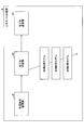
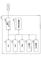
- FIG. 1 is a block diagram showing a schematic configuration of a material design system 1 according to an embodiment.
- the material design system 1 is an apparatus for designing a material to be designed including a material having a plurality of compositions or a material manufactured by a combination of a plurality of manufacturing conditions.
- the material design system 1 can be applied to the design of organic materials such as synthetic rubber, synthetic resin and synthetic elastomer, metal materials such as alloys and steel, and general materials such as inorganic materials and composite materials.
- the material to be designed by the material design system 1 depends on a material having a plurality of compositions or a combination of a plurality of manufacturing conditions / treatments (temperature, pressure, processing, oxidation treatment, acid treatment, compounding, mixing, stirring, etc.). Includes all materials manufactured.
- the material design system 1 includes a single expert terminal 2 and a plurality of (two in FIG. 1) general-purpose terminals 3.
- the expert terminal 2 is a device that can use the interface I1 for model learning.
- the model learning interface I1 is an interface for performing machine learning of a model whose input / output is the correspondence between the design condition of the material to be designed and the material property value.
- the model learning interface I1 is a GUI (graphical user interface) or an API (application programming interface) for using command programming.
- the model learning interface I1 of the expert terminal 2 is used by a machine learning expert such as a data scientist.
- the general-purpose terminal 3 is a device that can use the material design interface I2 for the specific design target material.
- the material design interface I2 estimates the material property value from the design condition or estimates the design condition from the material property value by using the trained model for the specific design target material created by the expert terminal 2. It is an interface to do.
- the material design interface I2 is a GUI with high user operability.
- the material design interface I2 of the general-purpose terminal 3 is used by a non-skilled person in machine learning such as a material designer, that is, a non-data scientist.
- the general-purpose terminal 3 is installed in each of a plurality of design departments in the company. At this time, the general-purpose terminal 3 does not have to be installed in all departments.
- two departments, department A and department B, are illustrated.
- materials A and B are designed as design target materials
- materials B and C are designed as design target materials. The case where it is done is illustrated.
- the expert terminal 2 creates a trained model using the model learning interface I1.
- the expert terminal 2 and the general-purpose terminal 3 are communicably connected, and the learned model is transmitted from the expert terminal 2 to each general-purpose terminal 3.
- the expert terminal 2 creates three types of trained models used for the materials A, B, and C of the material to be designed, and uses the trained model according to the material handled by each department as a general-purpose terminal of each department. Send to 3.
- the trained model for material A and the trained model for material B are transmitted to the general-purpose terminal 3 of department A that handles materials A and B, and the general-purpose terminal 3 of department B that handles materials B and C.
- the trained model for material B and the trained model for material C are transmitted to.
- the model learning interface I1 and the material design interface I2 which can operate independently, can be linked by a network connection or the like.
- the material design interface I2 is configured so that a non-data scientist material developer can design a material without performing machine learning.
- the interface I2 for material design has a highly versatile design regardless of the type of material, and by providing information by file transfer from the interface I1 for model learning, it is possible to develop all kinds of materials. It is configured to be applicable.
- the number of expert terminals 2 that can use the model learning interface I1 is smaller than that of the general-purpose terminals 3 that can use the material design interface I2, and each terminal 2 3 is another device.
- the material design system 1 according to the present embodiment can share the trained model created by the expert terminal 2 with many general-purpose terminals 3, so that the know-how of a small number of machine learning experts can be utilized.
- High-quality machine learning learning results can be used in multiple material design departments. That is, it is possible to obtain the effect that a wide range of high-quality machine learning learning results can be used.
- the material design system 1 of the present embodiment only secures a small number of data scientists by providing a small number of expert terminals 2 for the general-purpose terminal 3 as described above. Therefore, it is possible to deploy a system that efficiently supports material design to a large number of material development departments inside or outside the organization of a material manufacturer.
- the configuration in which the material design system 1 is installed in one company and the general-purpose terminals 3 are installed in each of a plurality of design departments in the company is illustrated, but the installation mode of the material design system 1 is this. Not limited to.
- one material design system 1 may be installed across a plurality of companies or organizations, and a general-purpose terminal 3 may be installed for each company or organization.
- the material design system 1 may be installed in one group, and a plurality of general-purpose terminals 3 may be installed in this group according to the application.
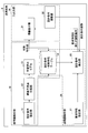
- FIG. 2 is a block diagram showing a modified example of the schematic configuration of the material design system 1 according to the embodiment.
- the material design system 1 may be configured to include an intermediate device 4 that stores a trained model created by the expert terminal 2.
- the plurality of general-purpose terminals 3 use the trained model stored in the intermediate device 4 to estimate the material property value from the design condition or the design condition from the material property value.
- each general-purpose terminal 3 can access and use the trained model stored in the intermediate device 4, so that each general-purpose terminal 3 uses the trained model. Therefore, it is not necessary to individually distribute the trained model data to each terminal, and machine learning can be performed more easily using the trained model. Further, since the availability of each general-purpose terminal 3 can be set by the access right to each trained model of the intermediate device 4, it is easy to manage the allocation of the trained models that can be used by each general-purpose terminal 3. it can.
- the communication between the expert terminal 2 and the general-purpose terminal 3, that is, the communication between the model learning interface I1 and the material design interface I2 can be realized in the following three forms, for example.
- the server (expert terminal 2) on which the model learning interface I1 is installed and the server (general-purpose terminal 3) on which the material design interface I2 is installed are connected by a network, and the model learning interface I1 Information such as learned models and name files (material names, material property names, design condition item names) can be transferred from the server of the material design interface I2 to the server of the material design interface I2.
- the trained model takes the format of pickle file, joblib file, etc.
- the name file takes the format of text file, CSV file, JSON file, XML file, etc.
- the above-mentioned method of providing information is not limited to file transfer, and may be a format for transferring information held in a recording medium such as a semiconductor memory such as a flash memory or a disk medium such as a DVD-ROM.
- Information may be transferred from the model learning interface I1 to the material design interface I2 directly from the model learning interface I1 server to the material design interface I2 server, as shown in FIG. Then, as shown in FIG. 2, after transferring from the model learning interface I1 to the intermediate server or directory (intermediate device 4), the material design interface I2 is allowed to access the intermediate device 4. You may.
- model learning interface I1 and the material design interface I2 are mounted on the cloud server, and the communication between the model learning interface I1 and the material design interface I2 is performed by communication in the cloud server. ..
- the model learning interface I1 and the material design interface I2 are separate interfaces installed in cloud servers such as AWS (registered trademark; Amazon Web Services) and GCP (registered trademark; Google Cloud Platform). Therefore, communication within the cloud server is secured. From the instance of the interface I1 for model learning in the cloud server to the instance of the interface I2 for material design, information about the trained model and name is transferred to a file, or a semiconductor memory such as a flash memory, a DVD-ROM, etc. It is transmitted in the form of transfer of information held in a recording medium such as disk media.
- Information transfer from the model learning interface I1 to the material design interface I2 may be performed directly from the instance of the model learning interface I1 to the instance of the material design interface I2, as shown in FIG. Then, as shown in FIG. 2, after transferring from the model learning interface I1 to the intermediate instance or the directory (intermediate device 4), the material design interface I2 is allowed to access the intermediate device 4. You may.
- the software of the interface I1 for model learning can output the trained model and the name file to the outside, and the software of the interface I2 for material design can read the trained model and the name file.
- the configuration in which the expert terminal 2 that can use the model learning interface I1 and the general-purpose terminal 3 that can use the material design interface I2 are separate devices has been illustrated.
- At least one of the expert terminal 2 and the general-purpose terminal 3 may be the same device. If a large number of material design interfaces I2 can be used for the model learning interface I1 even in a single device, the know-how of a small number of machine learning experts can be utilized for high-quality machine learning.
- the learning results can be used in multiple material design departments. That is, it is possible to obtain the effect that a wide range of high-quality machine learning learning results can be used.
- FIG. 3 is a functional block diagram of the expert terminal 2.
- the expert terminal 2 includes a learning condition setting unit 41, a model learning unit 42, and a model transmission unit (model output unit) 43.
- the learning condition setting unit 41 sets various conditions for machine learning of the model.
- 4 to 9 are diagrams showing an example of input screens 41A to 41F of the learning condition setting unit 41 in the model learning interface I1.
- the input screen 41A is displayed as a tabbed window of "data visualization".
- the model learning interface I1 has a function of reading a data file such as a CSV format, and in FIG. 4, a data file "Y alloy data.csv" is selected and read in the file selection box 40A.
- a large number of sets of model input (design conditions) and model output (material property values) data sets related to Y alloy are recorded.
- the data set included in the read data file is displayed in a table, and the numerical values included in the data set are shown in a histogram, a scatter diagram, or the like.
- the input screen 41B is displayed as a tabbed window of "data division". On the input screen 41B, it is possible to input numerical values of various conditions (ratio of test data, random seed, etc.) on how to divide the data set included in the read data file into training data and test data. ..
- the input screen 41C is displayed as a tabbed window of "preprocessing".
- the settings for converting and normalizing the variables included in the data set using functions and the like, and the dimensions of the variables included in the data set are, for example, principal component analysis (PCA (principal component analysis)). It is possible to input settings for compression using, settings for assigning variables included in the dataset to the objective variables of the model, and explanatory variables.
- PCA principal component analysis
- the "+" button 41C1 is displayed in the item field of variable conversion. For example, by pressing the "+" button 41C1, an entry field such as a method can be added. ..
- the input screen 41D is displayed as a tabbed window of "machine learning”. On the input screen 41D, it is possible to input the selection of the machine learning method and the setting of hyperparameter tuning.
- "(100, 1000, 100)" is entered as the range of the hyper-tuning parameter, but these numerical values are (minimum, maximum, step size) of the range of the hyper-tuning parameter. Is shown.
- the input screen 41E is displayed as a tabbed window of "accuracy verification".
- a function setting for evaluating the prediction accuracy of the trained model by cross-validation a function setting for evaluating the prediction accuracy of the trained model using test data, and a prediction result by the trained model are shown. It is possible to enter the setting of the function to be performed.
- the input screen 41F is displayed as a "name creation" tabbed window.
- the trained model is output to the outside after designating the model name and the material name.
- material names, material property names, and design condition item names can be input, and settings for outputting them to the outside in the form of text files, CSV files, JSON files, XML files, etc. can be input. It has become.
- Each name of the material property name and the design condition item name can be manually input, or the name described in the read data file may be mechanically reflected.
- the material property name file and design condition item name file are linked to the material name. In the material property name file and the design condition item name file, only each name of the material property name and the design condition item name may be input, or the default value of the range of possible values may be input.
- the input screens 41A to 41F may be switched by tabs as shown in FIGS. 4 to 9, and analysis is performed using icons corresponding to the functions provided in the input screens 41A to 41F and arrows connecting the icons.
- a flow may be configured and learning conditions may be set according to the analysis flow.
- the model learning unit 42 performs machine learning of the model based on various conditions set by the learning condition setting unit 41.
- machine learning of the model is performed under the learning conditions set in FIGS. 4 to 8.
- machine learning is performed on the "model for material A”, the "model for material B”, and the “model for material C” assigned to the materials A, B, and C of the design target material, respectively.
- the trained models used for the design of materials A, B, and C are individually created.
- model learning unit 42 machine learning such as regression and classification can be performed, and the methods include linear, generalized linear (Lasso, Ridge, elastic net, logistic), kernel ridge, Bayesridge, Gaussian process, and so on. K-nearest neighbor method, decision tree, random forest, adder boost, bagging, gradient boosting, support vector machine, neural network, deep learning, etc. can be used.
- the model transmission unit 43 outputs the trained model. After designating the model name and material name, the trained model is output to the outside by pressing the "model output" button 40C of the model learning interface I1. Further, by pressing the "name output” button 40D, a name file including various names (material name, material property name, design condition item name) set in FIG. 9 is output to the outside.
- the expert terminal 2 outputs a learning condition setting unit 41 that sets various conditions for machine learning of the model, a model learning unit 42 that performs machine learning of the model based on various conditions, and a model that outputs the trained model 13.
- a transmission unit 43 is provided. This makes it possible to finely adjust various conditions for machine learning of the model, so that machine learning suitable for various uses can be performed. Further, the expert terminal 2 is particularly effective when used by a machine learning expert such as a data scientist, because more appropriate condition setting can be expected based on the knowledge of the expert.
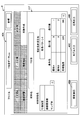
- FIG. 10 is a functional block diagram of the general-purpose terminal 3.
- the general-purpose terminal 3 includes a forward problem analysis unit 10, an inverse problem analysis unit 20, and an input / output unit 30.
- the forward problem analysis unit 10 uses the trained model 13 to output material properties that satisfy the design conditions desired by the material designer.
- the inverse problem analysis unit 20 outputs the design conditions satisfying the desired characteristics required by the material designer by using the design condition-material property table 14 created based on the output result of the forward problem analysis unit 10.
- the input / output unit 30 displays the output results of the forward problem analysis unit 10 and the inverse problem analysis unit 20 and presents them to the material designer, and accepts the adjustment operation of the output results by the material designer.
- the forward problem analysis unit 10 has a design condition setting unit 11, a comprehensive prediction point generation unit 12, a trained model 13, and a design condition-material property table 14.
- the design condition setting unit 11 sets a designated range of design conditions for the material to be designed. For example, the design condition setting unit 11 displays a design condition input screen on the material design interface I2 and prompts the material designer to input the type of the design target material and the specified range of the design condition.
- the specified range of design conditions can be set.
- FIG. 11 is a diagram showing an example of the input screen 11A of the design condition setting unit 11 in the material design interface I2.
- the input screen 11A is displayed as a tabbed window of "design conditions".
- a pull-down list 10A for selecting a material name to be designed is displayed, and in FIG. 11, "Y alloy" is selected as the material to be designed.
- the design condition setting unit 11 can read the name file described with reference to FIG. 9 and create a pull-down list 10A of selectable material names. Further, the design condition setting unit 11 reads the trained model associated with the selected material name.
- the design conditions include items related to the composition of raw materials (“raw material A” and “raw material B” in FIG. 11) and items related to manufacturing conditions (“processing temperature” in FIG. 11).
- the condition pattern can be selected from the pull-down menu.
- the design condition setting unit 11 reads the name file described with reference to FIG. 9 and creates a pull-down menu of selectable condition patterns. The items that can be selected as the condition pattern are determined by being associated with the material name.
- the materials of raw material composition for example, when the material to be designed is an aluminum (Al) alloy, Si, Fe, Cu, Mn, Mg, Cr, Ni, Zn, Ti, Na, V, Pb, Sn, B, Bi , Zr, O and other elemental species are included as additives in a mass percentage (mass%).
- the mass percentage of Al is represented by 100%-(the sum of the mass percentages of the above elements).
- the items related to heat treatment include annealing, solution treatment, artificial aging hardening treatment, natural aging treatment, hot working treatment, cold working treatment, and stabilizing treatment.
- the items related to the processing conditions include the temperature (° C.) and the implementation time (h) of each treatment such as, and include the processing rate, pressing ratio, surface reduction rate, product shape, and the like.
- the process of the forward problem analysis unit 10 is started by pressing the "analysis execution" button 10B of the material design interface I2.
- the coverage prediction point generation unit 12 generates a plurality of coverage prediction points within the specified range of the design conditions set by the design condition setting unit 11. For example, when the Si mass percentage of the composition item and the range of the annealing implementation time of the manufacturing condition item are specified, first, the specified range of the Si mass percentage and the specified range of the annealing implementation time are randomly or respectively. A plurality of numerical values are calculated with a predetermined step size, and all combinations of the plurality of numerical values of each item are created. These combinations are output as comprehensive prediction points.
- the trained model 13 has already acquired and formulated the correspondence between the input information including the design conditions of the material to be designed and the output information including the material property values by machine learning.
- the trained model 13 in the example of FIG. 11, the trained model used when the design target material is “Y alloy” is created by the expert terminal 2, and the general-purpose terminal 3 can be used.
- Items of material properties include tensile strength, 0.2% strength, elongation, linear expansion coefficient, Young's modulus, Poisson ratio, fatigue properties, hardness, creep properties including creep strength and creep strain, shear strength, specific heat, and heat. Includes conductivity, electrical resistance, density, solid phase, liquid phase, etc.
- FIG. 12 is a diagram showing an example of the output screen 31A of the forward problem analysis unit 10 in the material design interface I2.
- this output screen 31A is displayed as a tabbed window of "result (material property)".
- the output screen 31A is displayed on the material design interface I2 via, for example, the information display unit 31.
- the output (material property) of the trained model 13 is limited to only three, “tensile strength”, “coefficient of linear expansion”, and “Young's modulus” for the sake of simplification of explanation. Absent.
- the range of values of each material property is displayed by a box plot.
- the design condition-material property table 14 is a data set in which the material characteristic values calculated by inputting the comprehensive prediction points generated by the comprehensive prediction point generation unit 12 into the trained model 13 are associated with each point of the comprehensive prediction points.
- the forward problem analysis unit 10 calculates the coverage prediction point by the trained model 13
- the output is associated with the coverage prediction point (input) and stored in the design condition-material property table 14.
- the input (manufacturing condition, material composition) and output (material property) of the trained model are collected as one data set and recorded in the same row of the design condition-material property table 14. Will be done.
- Each row of the design condition-material property table 14 is an individual data set, and each column records the numerical value of each item of the input and output of the trained model 13.
- the design condition-material property table 14 is stored in association with the material name selected on the input screen 11A of FIG.
- the forward problem analysis unit 10 has the design conditions and material properties that cover the entire range of the multidimensional design conditions only by the material designer performing an operation of designating the range of the multidimensional design conditions. It is configured so that datasets can be automatically generated.
- the inverse problem analysis unit 20 has a required characteristic setting unit 21 and a design condition extraction unit 22.
- the above-mentioned design condition-material property table 14 is also included in the inverse problem analysis unit 20.
- the required characteristic setting unit 21 sets a designated range of required characteristics of the material to be designed.
- the required characteristic setting unit 21 can set the specified range of the required characteristic by displaying the input screen of the required characteristic on the material design interface I2 and prompting the material designer to input the specified range, for example.
- FIG. 13 is a diagram showing an example of the input screen 21A of the required characteristic setting unit 21.
- the input screen 21A is displayed as a tabbed window of "required characteristics".
- a pull-down list 10A for selecting a material name to be designed is displayed, and in FIG. 13, “Y alloy” is selected as the material to be designed.
- the required characteristic setting unit 21 can read the name file described with reference to FIG. 9 and create a pull-down list 10A of selectable material names. Further, the required characteristic setting unit 21 reads the design condition-material characteristic table 14 associated with the selected material name.
- the required property items are the same as the material property items described above.
- the characteristic name can be selected from the pull-down menu.
- the design condition setting unit 11 reads the name file described with reference to FIG. 9 and creates a pull-down menu of selectable characteristic names. Items that can be selected as characteristic names are determined in association with the material name. In the example of FIG. 13, "tensile strength", “linear expansion coefficient” and "Young's modulus” are selected as the required characteristics. Further, on the input screen 21A, the maximum value and the minimum value of each characteristic can be input.
- the process of the inverse problem analysis unit 20 is started by pressing the "analysis execution" button 10B of the material design interface I2.
- the design condition extraction unit 22 extracts a data set satisfying the required characteristics set by the required characteristic setting unit 21 from the design condition-material characteristic table 14.
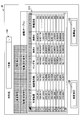
- FIG. 14 is a diagram showing an example of the output screen 31B of the inverse problem analysis unit 20.
- this output screen 31B is displayed as a tabbed window of "result (design condition)".
- the output screen 31B is displayed on the material design interface I2 via, for example, the information display unit 31.
- the range of values of the composition (raw material A, raw material B) and the production condition (processing temperature) satisfying all the required characteristics set in FIG. 13 is displayed by a box plot.
- the window with the tab of "Result (material property)" described above is switched, the range of the value of each material property is updated and displayed to the range of the value of each material property corresponding to the design condition shown in FIG. Will be done.
- FIG. 15 is a diagram showing an output screen 31C which is another example of the output screen of the inverse problem analysis unit 20.
- this output screen 31C is displayed as a tabbed window of "result (table)".
- the output screen 31C is displayed on the material design interface I2 via, for example, the information display unit 31.
- the required characteristics tensile strength, coefficient of linear expansion, Young's modulus
- the design conditions raw material A, raw material B, processing
- a table is displayed in which each value of (temperature) is summarized. Further, this table may be in a mode in which the display portion of the table can be moved by the scroll bar.
- the table shown in FIG. 15 can be output to the outside in a format such as a CSV file.
- the inverse problem analysis unit 20 extracts design conditions (material composition or manufacturing conditions) that simultaneously satisfy the multidimensional required characteristics simply by the material designer performing an operation of specifying a range of the multidimensional required characteristics. It is configured so that it can be done. Further, since the design condition-material property table 14 created by the forward problem analysis unit 10 is diverted without using a simulation or a learning model for the inverse problem analysis, the calculation cost can be significantly reduced.
- the input / output unit 30 has an information display unit 31.
- the information display unit 31 displays the output of the forward problem analysis unit 10 and the inverse problem analysis unit 20. For example, as shown in FIGS. 14 and 15, the required characteristics and the range of design conditions related to the data set extracted by the design condition extraction unit 22 are displayed.
- the input / output unit 30 may further include a design condition adjusting unit 32.
- the design condition adjustment unit 32 adjusts the range of design conditions of the data set extracted by the design condition extraction unit 22.
- the design condition adjusting unit 32 can adjust the range of the design condition by, for example, the operation input of the material designer who changes the composition range of the output screen 31B displayed on the material design interface I2.
- the design condition extraction unit 22 can further narrow down the data set group extracted according to the required characteristics to the data set group that satisfies the design condition adjusted by the design condition adjustment unit 32 described above.
- the inverse problem analysis unit 20 outputs design conditions that satisfy the required characteristics, but these design conditions are automatically extracted from the comprehensive prediction points of the design conditions-material property table 14, and the actual manufacturing difficulty is difficult. Manufacturing constraints such as degree are not taken into account. For example, it is difficult to handle and actually make, it takes a long time to make, it takes time to process, the composition that nests when casting, it can not be molded, it can be manufactured if cost is not considered, but with ordinary factory equipment There are various manufacturing restrictions such as not being able to make it.
- the output result of the inverse problem analysis unit 20 can be adjusted by the material designer using the design condition adjusting unit 32, so that the manufacturing conditions satisfying the required characteristics can be obtained. , It can be narrowed down in consideration of manufacturing restrictions based on the empirical rules of material designers. In other words, it is possible to design materials in which prediction by machine learning and the experience of material designers collaborate.
- the data set group used in the inverse problem analysis is created and stored in the design condition-material property table 14. Then, when performing the inverse problem analysis, a data set satisfying the required characteristics is extracted with reference to the design condition-material property table 14.
- the calculation cost can be significantly reduced and the desired material properties are satisfied because only the work of searching the design condition-material property table 14 is performed without performing any numerical calculation such as simulation or model calculation.
- the optimum solution of the design conditions can be derived in a short time.
- the search for candidate materials can be collectively performed so as to satisfy the properties of a plurality of types of materials at the same time.
- the time required to derive the optimum solution can be significantly reduced as compared with the conventional method.
- the data set group stored in the design condition-material property table 14 is information derived from a large number of comprehensive prediction points automatically generated in the forward problem analysis, the step size of each item of the design condition and material property is Is small enough and the resolution is high. Therefore, even in the inverse problem analysis, it is possible to predict the design conditions satisfying the required characteristics with high accuracy.
- the general-purpose terminal 3 includes a design condition adjusting unit 32 that adjusts a range of design conditions of the data set extracted by the design condition extracting unit 22.
- the design condition extracting unit 22 further narrows down the data set satisfying the design condition adjusted by the design condition adjusting unit 32 from the extracted data set.
- the design condition extraction unit 22 narrows down the design conditions mechanically extracted by the design condition-material characteristic table 14 according to the required characteristics by adding manufacturing restrictions based on the experience of the material designer. be able to. This makes it possible to design materials in which prediction by machine learning and the experience of material designers collaborate, and it is possible to extract design conditions that are easier to manufacture.
- the general-purpose terminal 3 includes an information display unit 31 that displays the required characteristics and the range of design conditions related to the data set extracted by the design condition extraction unit 22. Further, when the general-purpose terminal 3 has the design condition adjusting unit 32, the design condition adjusting unit 32 adjusts the range of the design condition according to the user operation for changing the range of the design condition displayed on the information display unit 31. ..
- the material designer can more intuitively perform the adjustment operation of the range of the design condition on the input / output unit 30, and the load of the adjustment operation can be reduced and simplified. .. Further, since the result of the adjustment operation can be immediately reflected, the material designer can perform the interactive adjustment operation, and the range of the design condition can be adjusted more efficiently.
- the design target material is selected by the pull-down list 10A for selecting the design target material name.
- FIG. 16 is a block diagram showing the hardware configurations of the expert terminal 2 and the general-purpose terminal 3.
- the expert terminal 2 and the general-purpose terminal 3 physically include a CPU (Central Processing Unit) 101, a RAM (Random Access Memory) 102 as a main storage device, and a ROM (Read Only Memory) 103.
- It is configured as a computer system including an input device 104 such as a keyboard and a mouse as an input device, an output device 105 such as a display, a communication module 106 as a data transmission / reception device such as a network card, and an auxiliary storage device 107 such as a hard disk. Can be done.
- Each function of the expert terminal 2 shown in FIG. 3 and each function of the general-purpose terminal 3 shown in FIG. 10 can be performed by loading predetermined computer software (material design program) on hardware such as the CPU 101 and the RAM 102. This is achieved by operating the communication module 106, the input device 104, and the output device 105 under control, and reading and writing data in the RAM 102 and the auxiliary storage device 107. That is, by executing the material design program of the present embodiment on a computer, the material design system 1 has the learning condition setting unit 41 of FIG. 3, the model learning unit 42, the model transmission unit 43, and the design conditions of FIG.
- a setting unit 11 It functions as a setting unit 11, a comprehensive prediction point generation unit 12, a learned model 13, a required characteristic setting unit 21, a design condition extraction unit 22, an information display unit 31, and a design condition adjustment unit 32, respectively.
- a learning function that performs machine learning of a model that inputs and outputs the correspondence between the design conditions of the design target material and the material property value, and a specific design target material created by the learning function for a specific design target material. It is also possible to realize an estimation function of estimating the material property value from the design condition or estimating the design condition from the material property value by using the trained model 13 for.
- the data set in which the material characteristic values calculated by inputting the comprehensive prediction points generated by the comprehensive prediction point generation function into the trained model 13 and being associated with each point of the comprehensive prediction points is set as the design condition-material property table 14. It is also possible to realize a data set creation function to be stored in.
- the design condition-material property table 14 shown in FIG. 10 can be realized by a part of the storage devices (RAM 102, ROM 103, auxiliary storage device 107, etc.) provided in the computer.
- the model learning interface I1 and the material design interface I2 shown in FIGS. 1 and 2 and the input / output unit 30 shown in FIG. 10 can be realized by the output device 105 and the input device 104 provided in the computer.
- the material design program of this embodiment is stored in, for example, a storage device provided in a computer.
- a part or all of the material design program may be transmitted via a transmission medium such as a communication line, and may be received and recorded (including installation) by a communication module or the like provided in the computer.
- the material design program has a configuration in which a part or all of the material design program is recorded (including installation) in a computer from a state in which a part or all of the program is stored in a portable storage medium such as a CD-ROM, a DVD-ROM, or a flash memory. May be.
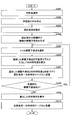
- FIG. 17 is a flowchart of the model learning process executed by the expert terminal 2.
- step S101 the learning condition setting unit 41 reads the data file for model learning. For example, as shown in the input screen 41A of FIG. 4, the data file is selected and read according to the operator's selection operation using the file selection box 40A of the model learning interface I1.
- step S102 the learning condition setting unit 41 visualizes the read data. For example, as shown in the input screen 41A of FIG. 4, the data set included in the read data file is displayed in a table, and the numerical values included in the data set are shown in a histogram, a scatter diagram, or the like.
- step S103 the learning condition setting unit 41 divides the data set included in the read data file into training data and test data. For example, as shown in the input screen 41B of FIG. 5, the data is divided based on various conditions set by the operator.
- step S104 the model learning unit 42 preprocesses the data set for model learning. For example, as shown in the input screen 41C of FIG. 6, preprocessing such as variable transformation and normalization is performed based on various conditions related to preprocessing set by the operator.
- step S105 the model learning unit 42 executes machine learning of the model. For example, as shown in the input screen 41D of FIG. 7, machine learning of the model is performed based on various conditions related to machine learning set by the operator.
- step S106 the model learning unit 42 verifies the prediction accuracy. For example, as shown in the input screen 41E of FIG. 8, the verification process is performed based on various conditions of accuracy verification set by the operator.
- step S107 the model learning unit 42 determines whether or not the prediction accuracy is sufficient. For example, as shown in the input screen 41E of FIG. 8, it can be determined that the prediction accuracy is sufficient when the condition of the verification result set by the operator is satisfied. When the prediction accuracy is insufficient (No in step S107), the process returns to step S104 and machine learning of the model is repeated. When the prediction accuracy is sufficient (Yes in step S107), the process proceeds to step S108.
- step S108 the trained model is output as a file by the model transmission unit 43. Further, the model transmission unit 43 outputs the trained model and a name file including various names (material name, material property name, design condition item name) set in FIG. When the process of step S108 is completed, this control flow ends.
- a series of processes by the expert terminal 2 of the flowchart shown in FIG. 17 performs machine learning of a model in which the correspondence between the design condition of the material to be designed and the material property value is input / output in the material design method according to the present embodiment. Corresponds to "learning steps to be performed”.
- FIG. 18 is a flowchart of the forward problem analysis process executed by the forward problem analysis unit 10 of the general-purpose terminal 3.
- the general-purpose terminal 3 uses the trained model 13 in which the correspondence between the input information including the design conditions of the material to be designed and the output information including the material characteristic values is acquired by machine learning.
- Material design interface I2 is available.
- step S201 the design condition setting unit 11 selects the material name of the material to be designed. For example, as shown in the input screen 11A of FIG. 11, the material name is selected according to the operator's selection operation via the pull-down list 10A of the material design interface I2.
- step S202 the design condition setting unit 11 calls and reads the learned model associated with the material name selected in step S201.
- step S203 the design condition setting unit 11 sets a designated range of design conditions for the material to be designed (design condition setting step). For example, the design condition setting unit 11 displays the input screen 11A shown in FIG. 11 on the material design interface I2, and causes the material designer to input a designated range.
- step S204 the coverage prediction point generation unit 12 generates a plurality of coverage prediction points within the specified range of the design conditions set in step S203 (coverage prediction point generation step).
- the forward problem analysis unit 10 inputs the coverage prediction points generated in step S204 into the trained model 13, and the data characteristic values calculated are associated with each point of the coverage prediction points.
- the set is stored in the design condition-material property table 14 (data set creation step).
- step S205 one comprehensive prediction point is selected, and in step S206, the comprehensive prediction point selected in step S205 is input to the trained model 13 to calculate the material property value.
- step S207 the input coverage prediction point of the trained model 13 selected in step S205 and the material characteristic value of the output are associated and stored in the design condition-material characteristic table 14.
- One data set is generated by the processing of steps S205 to S207.
- step S208 it is determined whether or not there is an unselected comprehensive prediction point. If there is an unselected comprehensive prediction point (YES in step S208), the process returns to step S205 and the data set generation is repeated. If all the coverage prediction points have been selected (NO in step S208), the data set generation is completed and the process proceeds to step S209.
- step S209 the information display unit 31 displays the material properties of each coverage prediction point calculated in step S206 on the material design interface I2.
- the information display unit 31 displays, for example, the output screen 31A illustrated in FIG. 12 on the material design interface I2.
- step S210 the forward problem analysis unit 10 inputs the coverage prediction points generated by the coverage prediction point generation unit 12 into the trained model 13, and the material property values calculated are associated with each point of the coverage prediction points. Data sets are created and these data sets are stored in the design condition-material property table 14. The design condition-material property table 14 is stored in association with the material name selected on the input screen 11A of FIG. When the process of step S210 is completed, the forward problem analysis process of this control flow is completed.
- FIG. 19 is a flowchart of the inverse problem analysis process executed by the inverse problem analysis unit 20 and the design condition adjustment unit 32 of the general-purpose terminal 3.
- step S301 the material name of the material to be designed is selected by the required characteristic setting unit 21.
- the material name is selected according to the operator's selection operation via the pull-down list 10A of the material design interface I2.
- step S302 the required characteristic setting unit 21 calls and reads the design condition-material characteristic table 14 associated with the material name selected in step S301.
- step S303 the required characteristic setting unit 21 sets the specified range of the required characteristics of the material to be designed (required characteristic setting step).
- the required characteristic setting unit 21 displays, for example, the input screen 21A shown in FIG. 13 on the material design interface I2, and causes the material designer to input a designated range.
- step S304 the design condition extraction unit 22 extracts a data set satisfying the required characteristics set in step S303 from the design condition-material characteristic table 14 (design condition extraction step).
- step S305 the range of the material composition and the required characteristics that satisfy the required characteristics specified in step S303 are set on the material design interface I2 by using the data set extracted in step 304 by the information display unit 31. Is displayed in.
- the information display unit 31 displays, for example, the output screen 31B illustrated in FIG. 14 on the material design interface I2.
- step S306 the design condition adjusting unit 32 determines whether or not the material designer has operated the composition adjustment on the output screen 31B showing the range of the material composition satisfying the required characteristics.
- the material designer can perform an operation of changing the positions of the maximum value and the minimum value of the box plot of the material composition of the output screen 31B (design condition adjustment step).
- the design condition adjusting unit 32 outputs the information of the adjusted composition range to the design condition extraction unit 22, and proceeds to step S307. If there is no operation (No in step S306), the inverse problem analysis process of this control flow is terminated.
- step S307 since the composition adjustment operation was detected in step S306, the design condition extraction unit 22 narrows down the data satisfying the material composition after adjusting the composition range from the data set group extracted in step S304. (Narrowing down step).
- step S308 the information display unit 31 updates the output screen 31B of the required characteristics displayed in step S305 using the data set narrowed down in step 307.
- the process of step S308 is completed, the inverse problem analysis process ends.
- the series of processes by the general-purpose terminal 3 of the flowcharts shown in FIGS. 18 and 19 is for the specific design target material created in the learning step for the specific design target material in the material design method according to the present embodiment.
- the general-purpose terminal 3 may be configured to analyze only one of the forward problem and the inverse problem.
- the relationship between the model input and the output is replaced with that of the above embodiment, the model input is the material property, and the model output is the design condition.
- the inverse problem is analyzed using this trained model of the input / output relationship.
- the general-purpose terminal 3 may be configured to perform processing using the learned model 13 created by the expert terminal 2.
Landscapes
- Engineering & Computer Science (AREA)
- Physics & Mathematics (AREA)
- Theoretical Computer Science (AREA)
- Evolutionary Computation (AREA)
- Geometry (AREA)
- General Physics & Mathematics (AREA)
- General Engineering & Computer Science (AREA)
- Computer Hardware Design (AREA)
- Software Systems (AREA)
- Medical Informatics (AREA)
- Computer Vision & Pattern Recognition (AREA)
- Artificial Intelligence (AREA)
- Pure & Applied Mathematics (AREA)
- Mathematical Analysis (AREA)
- Mathematical Optimization (AREA)
- Computational Mathematics (AREA)
- Computing Systems (AREA)
- Life Sciences & Earth Sciences (AREA)
- Bioinformatics & Cheminformatics (AREA)
- Bioinformatics & Computational Biology (AREA)
- Management, Administration, Business Operations System, And Electronic Commerce (AREA)
- Feedback Control In General (AREA)
Priority Applications (4)
| Application Number | Priority Date | Filing Date | Title |
|---|---|---|---|
| EP20845049.4A EP4006764A4 (de) | 2019-07-23 | 2020-07-17 | Materialentwurfssystem, materialentwurfsverfahren und materialentwurfsprogramm |
| JP2021534006A JP6950119B2 (ja) | 2019-07-23 | 2020-07-17 | 材料設計システム、材料設計方法、及び材料設計プログラム |
| US17/628,292 US20220261510A1 (en) | 2019-07-23 | 2020-07-17 | Material design system, material design method, and material design program |
| CN202080052682.4A CN114144788A (zh) | 2019-07-23 | 2020-07-17 | 材料设计系统、材料设计方法及材料设计程序 |
Applications Claiming Priority (2)
| Application Number | Priority Date | Filing Date | Title |
|---|---|---|---|
| JP2019-135216 | 2019-07-23 | ||
| JP2019135216 | 2019-07-23 |
Publications (1)
| Publication Number | Publication Date |
|---|---|
| WO2021015134A1 true WO2021015134A1 (ja) | 2021-01-28 |
Family
ID=74192574
Family Applications (1)
| Application Number | Title | Priority Date | Filing Date |
|---|---|---|---|
| PCT/JP2020/027909 WO2021015134A1 (ja) | 2019-07-23 | 2020-07-17 | 材料設計システム、材料設計方法、及び材料設計プログラム |
Country Status (5)
| Country | Link |
|---|---|
| US (1) | US20220261510A1 (de) |
| EP (1) | EP4006764A4 (de) |
| JP (1) | JP6950119B2 (de) |
| CN (1) | CN114144788A (de) |
| WO (1) | WO2021015134A1 (de) |
Cited By (9)
| Publication number | Priority date | Publication date | Assignee | Title |
|---|---|---|---|---|
| JP2020198003A (ja) * | 2019-06-04 | 2020-12-10 | ジャパンモード株式会社 | 生成物推定プログラム及びシステム |
| JP7201763B1 (ja) | 2021-09-17 | 2023-01-10 | 株式会社神戸製鋼所 | 試作支援システム、及び、量産支援システム |
| WO2023002951A1 (ja) * | 2021-07-21 | 2023-01-26 | 昭和電工株式会社 | 材料設計支援装置、材料設計支援方法、及びプログラム |
| JP2023026082A (ja) * | 2021-08-12 | 2023-02-24 | 株式会社三菱総合研究所 | 情報処理装置、情報処理方法及びプログラム |
| WO2023120290A1 (ja) * | 2021-12-20 | 2023-06-29 | 株式会社レゾナック | 設計支援装置、設計支援方法、及びプログラム |
| WO2023171775A1 (ja) * | 2022-03-10 | 2023-09-14 | 日本碍子株式会社 | 材料創出を支援するシステム及び方法、プログラム |
| WO2023238525A1 (ja) * | 2022-06-10 | 2023-12-14 | 日本碍子株式会社 | 試作条件提案システム、試作条件提案方法 |
| JP7416155B1 (ja) | 2022-09-02 | 2024-01-17 | 株式会社プロテリアル | 樹脂組成物の物性予測装置及び方法 |
| WO2024085071A1 (ja) * | 2022-10-17 | 2024-04-25 | 株式会社レゾナック | 組成最適化装置、組成最適化方法及び組成最適化プログラム |
Citations (5)
| Publication number | Priority date | Publication date | Assignee | Title |
|---|---|---|---|---|
| JPH1153425A (ja) * | 1997-08-05 | 1999-02-26 | Sumitomo Chem Co Ltd | 合成ルート設計システム及び合成ルート設計プログラムを記録した機械読み取り可能な記録媒体 |
| JP2002318891A (ja) * | 2001-04-24 | 2002-10-31 | Toshiba Microelectronics Corp | 製品開発マネジメントシステム、製品開発マネジメント方法、製品信頼性判定システム及び製品信頼性判定方法 |
| JP2017091526A (ja) * | 2015-11-04 | 2017-05-25 | 三星電子株式会社Samsung Electronics Co.,Ltd. | 新規物質探索方法および装置 |
| JP2019023906A (ja) | 2014-05-23 | 2019-02-14 | データロボット, インコーポレイテッド | 予測データ分析のためのシステムおよび技術 |
| JP2019135216A (ja) | 2018-02-05 | 2019-08-15 | 日本曹達株式会社 | ベンズアルデヒド誘導体の製造方法 |
-
2020
- 2020-07-17 JP JP2021534006A patent/JP6950119B2/ja active Active
- 2020-07-17 EP EP20845049.4A patent/EP4006764A4/de active Pending
- 2020-07-17 US US17/628,292 patent/US20220261510A1/en active Pending
- 2020-07-17 WO PCT/JP2020/027909 patent/WO2021015134A1/ja unknown
- 2020-07-17 CN CN202080052682.4A patent/CN114144788A/zh active Pending
Patent Citations (5)
| Publication number | Priority date | Publication date | Assignee | Title |
|---|---|---|---|---|
| JPH1153425A (ja) * | 1997-08-05 | 1999-02-26 | Sumitomo Chem Co Ltd | 合成ルート設計システム及び合成ルート設計プログラムを記録した機械読み取り可能な記録媒体 |
| JP2002318891A (ja) * | 2001-04-24 | 2002-10-31 | Toshiba Microelectronics Corp | 製品開発マネジメントシステム、製品開発マネジメント方法、製品信頼性判定システム及び製品信頼性判定方法 |
| JP2019023906A (ja) | 2014-05-23 | 2019-02-14 | データロボット, インコーポレイテッド | 予測データ分析のためのシステムおよび技術 |
| JP2017091526A (ja) * | 2015-11-04 | 2017-05-25 | 三星電子株式会社Samsung Electronics Co.,Ltd. | 新規物質探索方法および装置 |
| JP2019135216A (ja) | 2018-02-05 | 2019-08-15 | 日本曹達株式会社 | ベンズアルデヒド誘導体の製造方法 |
Non-Patent Citations (1)
| Title |
|---|
| See also references of EP4006764A4 |
Cited By (11)
| Publication number | Priority date | Publication date | Assignee | Title |
|---|---|---|---|---|
| JP2020198003A (ja) * | 2019-06-04 | 2020-12-10 | ジャパンモード株式会社 | 生成物推定プログラム及びシステム |
| WO2023002951A1 (ja) * | 2021-07-21 | 2023-01-26 | 昭和電工株式会社 | 材料設計支援装置、材料設計支援方法、及びプログラム |
| JP2023026082A (ja) * | 2021-08-12 | 2023-02-24 | 株式会社三菱総合研究所 | 情報処理装置、情報処理方法及びプログラム |
| JP7270005B2 (ja) | 2021-08-12 | 2023-05-09 | 株式会社三菱総合研究所 | 情報処理装置、情報処理方法及びプログラム |
| JP7201763B1 (ja) | 2021-09-17 | 2023-01-10 | 株式会社神戸製鋼所 | 試作支援システム、及び、量産支援システム |
| JP2023044459A (ja) * | 2021-09-17 | 2023-03-30 | 株式会社神戸製鋼所 | 試作支援システム、及び、量産支援システム |
| WO2023120290A1 (ja) * | 2021-12-20 | 2023-06-29 | 株式会社レゾナック | 設計支援装置、設計支援方法、及びプログラム |
| WO2023171775A1 (ja) * | 2022-03-10 | 2023-09-14 | 日本碍子株式会社 | 材料創出を支援するシステム及び方法、プログラム |
| WO2023238525A1 (ja) * | 2022-06-10 | 2023-12-14 | 日本碍子株式会社 | 試作条件提案システム、試作条件提案方法 |
| JP7416155B1 (ja) | 2022-09-02 | 2024-01-17 | 株式会社プロテリアル | 樹脂組成物の物性予測装置及び方法 |
| WO2024085071A1 (ja) * | 2022-10-17 | 2024-04-25 | 株式会社レゾナック | 組成最適化装置、組成最適化方法及び組成最適化プログラム |
Also Published As
| Publication number | Publication date |
|---|---|
| JP6950119B2 (ja) | 2021-10-13 |
| US20220261510A1 (en) | 2022-08-18 |
| CN114144788A (zh) | 2022-03-04 |
| EP4006764A1 (de) | 2022-06-01 |
| EP4006764A4 (de) | 2022-09-14 |
| JPWO2021015134A1 (ja) | 2021-11-18 |
Similar Documents
| Publication | Publication Date | Title |
|---|---|---|
| WO2021015134A1 (ja) | 材料設計システム、材料設計方法、及び材料設計プログラム | |
| JP6976456B2 (ja) | 材料設計装置、材料設計方法、及び材料設計プログラム | |
| Idris et al. | Intelligent churn prediction for telecom using GP-AdaBoost learning and PSO undersampling | |
| Das | A comparative study of exponential distribution vs Weibull distribution in machine reliability analysis in a CMS design | |
| CN101903765B (zh) | 原油特性专家系统 | |
| JP5516390B2 (ja) | 品質予測装置、品質予測方法、プログラムおよびコンピュータ読み取り可能な記録媒体 | |
| US20130024173A1 (en) | Computer-Implemented Systems and Methods for Testing Large Scale Automatic Forecast Combinations | |
| CN102222125A (zh) | 工程设计优化中确定最大影响设计变量的方法和系统 | |
| US20200401113A1 (en) | Determining optimal material and/or manufacturing process | |
| CN106406999A (zh) | 计算系统和计算系统的执行控制方法 | |
| US11281937B2 (en) | Data analyzing device and data analyzing method | |
| Dostatni et al. | The use of machine learning method in concurrent ecodesign of products and technological processes | |
| JP2024516656A (ja) | 産業特定機械学習アプリケーション | |
| Sánchez | Interval-valued GA-P algorithms | |
| KR100991316B1 (ko) | 제조 설비에 관련된 예보를 생성하기 위한 시뮬레이션 사용 | |
| Savchenko et al. | Metamodeling as a way to universalization of inductive modeling tools | |
| Relich et al. | Knowledge discovery in enterprise databases for forecasting new product success | |
| Dan et al. | Application of machine learning in forecasting energy usage of building design | |
| JP7060130B1 (ja) | 運用支援装置、運用支援方法及びプログラム | |
| CN1265311C (zh) | 用于最优化一个断路器机构的方法 | |
| Araujo et al. | Hybrid intelligent design of morphological-rank-linear perceptrons for software development cost estimation | |
| Naik et al. | Project cost and duration optimization using soft computing techniques | |
| WO2023209983A1 (ja) | パラメータ生成装置、システム、方法およびプログラム | |
| Mehlstäubl et al. | Using machine learning for product portfolio management: a methodical approach to predict values of product attributes for multi-variant product portfolios | |
| Meitz et al. | StMAR Toolbox: A MATLAB Toolbox for Student's t Mixture Autoregressive Models |
Legal Events
| Date | Code | Title | Description |
|---|---|---|---|
| 121 | Ep: the epo has been informed by wipo that ep was designated in this application |
Ref document number: 20845049 Country of ref document: EP Kind code of ref document: A1 |
|
| ENP | Entry into the national phase |
Ref document number: 2021534006 Country of ref document: JP Kind code of ref document: A |
|
| NENP | Non-entry into the national phase |
Ref country code: DE |
|
| ENP | Entry into the national phase |
Ref document number: 2020845049 Country of ref document: EP Effective date: 20220223 |