WO2021014668A1 - 指訓練装置 - Google Patents
指訓練装置 Download PDFInfo
- Publication number
- WO2021014668A1 WO2021014668A1 PCT/JP2020/006565 JP2020006565W WO2021014668A1 WO 2021014668 A1 WO2021014668 A1 WO 2021014668A1 JP 2020006565 W JP2020006565 W JP 2020006565W WO 2021014668 A1 WO2021014668 A1 WO 2021014668A1
- Authority
- WO
- WIPO (PCT)
- Prior art keywords
- swivel
- finger
- motor
- control unit
- unit
- Prior art date
- Legal status (The legal status is an assumption and is not a legal conclusion. Google has not performed a legal analysis and makes no representation as to the accuracy of the status listed.)
- Ceased
Links
Images

















Classifications
-
- A—HUMAN NECESSITIES
- A61—MEDICAL OR VETERINARY SCIENCE; HYGIENE
- A61B—DIAGNOSIS; SURGERY; IDENTIFICATION
- A61B5/00—Measuring for diagnostic purposes; Identification of persons
- A61B5/22—Ergometry; Measuring muscular strength or the force of a muscular blow
-
- A—HUMAN NECESSITIES
- A61—MEDICAL OR VETERINARY SCIENCE; HYGIENE
- A61H—PHYSICAL THERAPY APPARATUS, e.g. DEVICES FOR LOCATING OR STIMULATING REFLEX POINTS IN THE BODY; ARTIFICIAL RESPIRATION; MASSAGE; BATHING DEVICES FOR SPECIAL THERAPEUTIC OR HYGIENIC PURPOSES OR SPECIFIC PARTS OF THE BODY
- A61H1/00—Apparatus for passive exercising; Vibrating apparatus; Chiropractic devices, e.g. body impacting devices, external devices for briefly extending or aligning unbroken bones
- A61H1/02—Stretching or bending or torsioning apparatus for exercising
Definitions
- the disclosed embodiment relates to a finger training device.
- Patent Document 1 describes a hemiplegic finger function recovery training device.
- This hemiplegic finger function recovery training device has a finger flexion / extension mechanism for causing the fingers of the trainee to perform passive flexion and automatic extension.
- the fingers have multiple joints for each finger, and their movements are complicated.
- the hemiplegic finger function recovery training device of the prior art is configured by combining a large number of rotation mechanisms and link mechanisms in order to regulate the movement of the fingers. Therefore, there is a problem that the structure becomes complicated.
- the present invention has been made in view of such problems, and an object of the present invention is to provide a finger training device capable of defining finger movements with a simple structure.
- a finger training device for performing training for recovering the motor function of the fingers, an orthosis for holding the fingertips of the fingers, and a first rotation.
- a first swivel member that swivels around an axis and moves the brace around the first swivel shaft, and a rotating member that rotates in conjunction with the swivel of the first swivel member to rotate the brace around a rotation axis.
- a finger training device with is applied.
- a finger training device for performing training for recovering the motor function of the fingers, a device for holding the fingertips of the fingers, and a device.
- a first swivel member that swivels around one swivel shaft and moves the orthosis around the first swivel shaft, a first motor that swivels the first swivel member around the first swivel shaft, and a second swivel shaft.
- a second swivel member that swivels around and moves the first swivel member and the first motor around the second swivel shaft, and a second motor that swivels the second swivel member around the second swivel shaft.
- a finger training device with is applied.
- the movement of fingers can be defined with a simple structure.
- FIG. 1 is a perspective view showing an example of the overall configuration of the finger training device according to the present embodiment
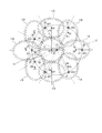
- FIG. 2 is an explanatory view showing an example of the operation of the gear mechanism.
- the finger training device 1 is a device that performs training for recovering the motor function of the fingers of the trainee and strengthening the muscle strength of the fingers.
- the training subjects are patients with motor dysfunction due to cerebrovascular diseases such as stroke and orthopedic diseases, for example.
- the finger training device 1 has a finger movement mechanism 3, a tapping mechanism 5, and a controller 7 (see FIG. 14 described later).
- the finger movement mechanism 3 and the tapping mechanism 5 are arranged adjacent to each other. Note that the controller 7 is not shown in FIG.
- the finger movement mechanism 3 is a mechanism for training various movements (flexion, extension, palm side abduction, palm side adduction) on the fingers of the trainee.
- the finger operation mechanism 3 includes a gantry 9, a first drive motor 11, a fixed gear 13, an arm 15, a planetary gear 17, and an orthosis 19. In FIG. 1, the teeth of the fixed gear 13 and the planetary gear 17, and the support base that supports the palm of the trainee are not shown.
- the pedestal 9 has a pair of legs 20 and a pedestal 21.
- the legs 20 may have a structure other than a pair, for example, a four-leg structure.
- the first drive motor 11 (an example of the first motor) is a rotary motor, and the arm 15 is swiveled around the swivel axis AX1 of the swivel shaft 23 (an example of the first swivel shaft).
- the first drive motor 11 is attached to the lower part of the pedestal portion 21 and is arranged between the pair of leg portions 20.
- the output shaft of the first drive motor 11 is connected to the swivel shaft 23, and the swivel shaft 23 is connected to one end of the arm 15.
- the output shaft of the first drive motor 11 may be connected to the swivel shaft 23 via a speed reducer.
- the rotational position of the first drive motor 11 is detected by the encoder 24 (an example of the rotational position sensor; see FIG.
- the first drive motor 11 is a servomotor whose position, speed, and torque are controlled by the controller 7 based on the detection result of the encoder 24.
- a rotation position sensor other than the encoder such as a resolver or a potentiometer, may be used.
- the fixed gear 13 is fixedly arranged on the upper part of the pedestal portion 21. That is, the fixed gear 13 is fixed to the pedestal portion 21 so as not to rotate. As shown in FIG. 2, the fixed gear 13 is a circular spur gear. Note that FIG. 2 shows a case where the fixed gear 13 has 30 teeth as an example, but the number of teeth is not limited to this.
- a swivel shaft 23 is rotatably inserted into the fixed gear 13 at a position offset from the gear center O1 by a predetermined distance d1.
- the swivel shaft 23 is rotatably supported by a bearing (not shown) provided on the fixed gear 13.
- the arm 15 (an example of the first swivel member) is arranged above the fixed gear 13 and swivels around the swivel shaft 23 (swivel axis AX1) to move the brace 19 around the swivel shaft 23.
- a swivel shaft 23 is connected to the vicinity of one end of the arm 15.
- a rotating shaft 25 of the planetary gear 17 is rotatably inserted in the vicinity of the other end of the arm 15.
- the arm 15 rotatably supports the rotating shaft 25 at the lower portion on the other side.
- the planetary gear 17 (an example of a rotating member) rotates in conjunction with the rotation of the arm 15, and rotates the brace 19 around the rotation axis AX2 of the rotation shaft 25.
- the planetary gear 17 is an elliptical spur gear (an example of a gear having a non-uniform radius), meshes with the fixed gear 13, and revolves around the fixed gear 13 while rotating on its axis.
- FIG. 2 shows an example in which the number of teeth of the planetary gear 17 is 30, the number of teeth is not limited to this. For example, the number of teeth of the fixed gear 13 and the number of teeth of the planetary gear 17 may be different.
- a rotating shaft 25 is vertically erected and connected to the planetary gear 17 at a position offset by a predetermined distance d2 in the long axis direction from the gear center O2.
- the rotating shaft 25 is rotatably supported by a bearing (not shown) provided on the arm 15.
- the planetary gear 17 is rotatably suspended and supported by an arm 15.
- the brace 19 holds the fingertips of the trainee's fingers.
- the "fingertip portion” refers to a portion on the tip side of the first joint of each finger.
- the first joint from the tip of each finger is referred to as a first joint
- the second joint is referred to as a second joint
- the third joint is referred to as a third joint. That is, in the case of the thumb, the first joint is an IP joint, the second joint is an MP joint, and the third joint is a CM joint.
- the first joint is a DIP joint
- the second joint is a PIP joint
- the third joint is an MP joint.
- the orthosis 19 has a pair of holding portions 27 for holding the fingertips, and a moving mechanism 29 for moving the holding portions 27 in the extending direction of the arm 15.
- the holding portion 27 is fixed by sandwiching the fingertip portion.
- the holding portion 27 is made of a flexible material such as rubber, resin, or urethane, and is deformed according to the thickness and shape of the finger so that the fingertip portion can be appropriately held.
- the moving mechanism 29 allows the holding portion 27 to move, for example, by loosening the screw 31, and fixes the holding portion 27 by tightening the screw 31 at a desired position. With such a configuration, the orthosis 19 can move the holding position of the fingertip portion in the extending direction of the arm 15 within a predetermined range.
- a force sensor 33 (an example of a measuring unit and a sensor) for measuring the force received by the device 19 from the fingertip portion may be provided inside each of the pair of holding portions 27.
- FIG. 1 illustrates a case where the force sensor 33 is provided.
- the force sensor 33 When the force sensor 33 is provided, the force in the tangential direction with respect to the trajectory of the fingertip can be measured, so that the force due to the voluntary movement of the trainee, the force due to the tendon or muscle, and the like can be accurately measured. Can be measured.
- a strain gauge for measuring the deflection of the rotating shaft 25 may be provided.
- the arm 15 is provided with a first attachment / detachment portion 35 and a second attachment / detachment portion 37 to which the orthosis 19 can be attached / detached.
- the first attachment / detachment portion 35 is arranged near the other end of the arm 15 and is connected to the upper portion of the rotation shaft 25.
- the orthosis 19 is arranged at a position where the fingers can be extended or bent by being attached to the first attachment / detachment portion 35 (see FIGS. 3 to 11 described later). Note that FIG. 1 shows a state in which the orthosis 19 is attached to the first attachment / detachment portion 35.
- the second attachment / detachment portion 37 is arranged at an intermediate position in the extending direction of the arm 15.
- the orthosis 19 is arranged at a position where the palm side abduction or palm side adduction of the thumb can be performed by being attached to the second attachment / detachment portion 37 (see FIGS. 12 and 13 described later).
- the attachment / detachment method of the first attachment / detachment portion 35 and the second attachment / detachment portion 37 is not particularly limited, but for example, a attachment / detachment method using a magnet or a screw can be used.
- the tapping mechanism 5 is a mechanism for tapping the vicinity of the base position of the finger to be trained when training the extension or flexion movement of the finger by the finger movement mechanism 3.
- the tapping mechanism 5 includes a gantry 39, a third drive motor 41, an arm 43, and a contact portion 45.
- the gantry 39 has a pair of legs 47 and a pedestal 49.
- the legs 47 may have a structure other than a pair, for example, a four-leg structure.
- the third drive motor 41 (an example of the third motor) is a rotary motor, and the arm 43 is swiveled around the swivel axis AX3 of the swivel shaft 51.
- the third drive motor 41 is attached to the lower part of the pedestal portion 49, and is arranged between the pair of leg portions 47.
- the output shaft of the third drive motor 41 is connected to the swivel shaft 51, and the swivel shaft 51 is connected to one end of the arm 43.
- the output shaft of the third drive motor 41 may be connected to the swivel shaft 51 via a speed reducer.
- the third drive motor 41 is controlled by the controller 7.
- the arm 43 is arranged above the pedestal portion 49, swivels around the swivel shaft 51, and moves the contact portion 45 around the swivel shaft 51 (swivel shaft center AX3).
- a swivel shaft 51 is connected to the vicinity of one end of the arm 43. Further, the height of the tip portion 43a on the other side of the arm 43 is adjusted by the bending portion 43b provided in the intermediate portion.
- the contact portion 45 is formed in a cylindrical shape, for example, and is erected at the tip portion 43a of the arm 43.
- the contact portion 45 is made of a flexible material such as rubber, resin, or urethane, and is contacted by the third drive motor 41 so as to tap near the base position of the finger to be trained. By tapping, it becomes possible to make the trainee aware of the movement timing of the finger, and the effect of the training can be further enhanced.
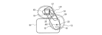
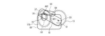
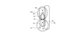
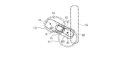
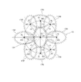
- FIGS. 2 and 3 to 13 are explanatory views showing a turning motion of the arm 15 and a rotating motion of the brace 19.
- FIG. 2 shows how the planetary gear 17 revolves around the fixed gear 13 while rotating on its axis.
- the distance between the rotating shaft 25 (rotating axis AX2) and the rotating shaft 23 (rotating axis AX1) is constant with a radius R. is there. That is, the rotating shaft 25 (rotating axis AX2) of the planetary gear 17 draws a circular locus having a radius R around the swirling shaft 23 (swivel axis AX1).
- FIG. 2 shows a state in which the planetary gear 17 rotates (rotates) by 90 degrees around the rotation shaft 25 (rotation axis AX2).
- a state in which the planetary gear 17 is positioned so that the rotary shaft 25 (rotary axis AX2) is positioned on the long axis so as to sandwich the gear center O2 with the swivel shaft 23 (swivel axis AX1) is shown.
- the planetary gear 17A is used.
- a state in which the planetary gear 17A is rotated 90 degrees in the counterclockwise direction around the rotating shaft 25 (rotating axis AX2) is referred to as the planetary gear 17B.
- the planetary gear 17C is the state in which the planetary gear 17B is rotated 90 degrees in the counterclockwise direction, and the planetary gear 17D and the planetary gear 17D are in the counterclockwise direction when the planetary gear 17C is rotated 90 degrees in the counterclockwise direction.
- the planetary gear 17E is rotated 90 degrees
- the planetary gear 17E is rotated 90 degrees counterclockwise
- the planetary gear 17F is rotated 90 degrees counterclockwise, the planetary gear 17G and the planetary gear.
- the state in which the 17G is rotated 90 degrees in the counterclockwise direction is referred to as the planetary gear 17H, and the state in which the planetary gear 17H is rotated 90 degrees in the counterclockwise direction is referred to as the planetary gear 17A.
- the radius of gyration of each of the planetary gears 17A, 17B, 17C, 17D, 17E, 17F, 17G, and 17H is Ra, Rb, Rc, Rd, Re, Rf, Rg, and Rh.
- the "rotation radius” referred to here is a planetary gear from the rotating shaft 25 (rotating axis AX2) on a straight line connecting the rotating shaft 25 (rotating axis AX2) and the rotating shaft 23 (rotating axis AX1). It refers to the distance to the contact position between the 17 and the fixed gear 13.
- the angular velocity of the planetary gear 17 can be changed while turning the arm 15 at the same angular velocity.
- the rotational speed (angle change) of the orthosis 19 fixed to the planetary gear 17 is also changed as desired depending on which range of the angle range shown in FIG. 2 is set for the turning range of the arm 15. ,
- the trajectory of the fingertip portion held by the brace 19 can be changed.
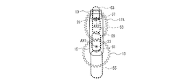
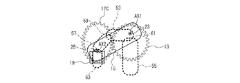
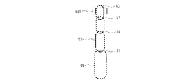
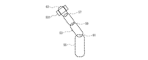
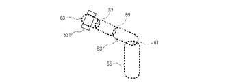
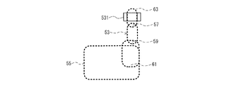
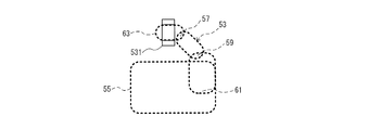
- FIGS. 3 to 5 show an example of the turning operation of the arm 15 and the rotating operation of the equipment 19 when the arm 15 is rotated in the angle range of the planetary gears 17A to 17C.
- the fingers in this example, the index finger, the middle finger, the ring finger, and the four fingers of the little finger
- the turning start position is a position where the turning radius of the planetary gear 17 is the maximum turning radius Ra (an example of an angle position close to the angle position where the turning radius is the longest than the angle position where the turning radius is the shortest).
- the turning start position is set at a position where the turning radius of the planetary gear 17 is the turning radius Rc (an example of an angle position close to the angle position where the turning radius is the shortest than the longest turning angle position).
- Rc an example of an angle position close to the angle position where the turning radius is the shortest than the longest turning angle position.
- the vehicle turns toward an angle position where the radius of gyration is the longest (a position where the radius of gyration is Ra).
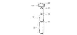
- the first joint 57, the second joint 59, the third joint 61, and the fingertip portion 63 of the fingers 53, palm 55, and fingers 53 are conceptually shown by broken lines. Further, the illustration of the moving mechanism 29 and the like is omitted. As shown in FIGS. 3 to 5, in the finger 53, the first joint 57 is located on the approximate rotation axis 25 (rotation axis AX2), and the rotation axis 23 (swivel axis AX1) is approximately the second joint 59. It is attached to the device 19 which has been moved to an appropriate position by the moving mechanism 29 so as to be located between the third joint 61.
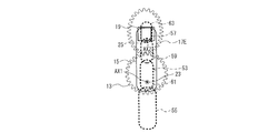
- FIGS. 6 to 8 show an example of the turning operation of the arm 15 and the rotating operation of the equipment 19 when the arm 15 is rotated in the angle range of the planetary gears 17E to 17G.
- the fingers in this example, the index finger, the middle finger, the ring finger, and the four fingers of the little finger
- the turning start position is a position where the turning radius of the planetary gear 17 is the minimum turning radius Re (an example of an angle position close to the angle position where the turning radius is the shortest than the longest turning radius position).
- the turning start position is set at a position where the turning radius of the planetary gear 17 is the turning radius Rg (an example of an angle position close to the angle position where the turning radius is the shortest than the longest turning angle position).
- Rg an example of an angle position close to the angle position where the turning radius is the shortest than the longest turning angle position.
- This is an example of turning toward an angular position (position where the turning radius is Re) where the turning radius is the shortest.
- the first joint 57 is located on the approximate rotation axis 25 (rotation axis AX2), and the rotation axis 23 (swivel axis AX1) is approximately the second joint 59. It is attached to the device 19 which has been moved to an appropriate position by the moving mechanism 29 so as to be located between the third joint 61.
- the rotation of the planetary gears 17 is performed when the fingers 53 are bent in the order of FIGS. 6, 7, and 8. The speed can be gradually changed from high speed to low speed.
- FIGS. 9 to 11 show an example of the turning motion of the arm 15 and the rotating motion of the orthosis 19 when the arm 15 is swiveled in the angle range of the planetary gears 17E to 17G for the thumb.
- the thumb is bent, and when the operations are performed in the order of FIGS. 11, 10 and 9, the thumb is extended.
- the turning start position is set at the position where the turning radius of the planetary gear 17 is the minimum turning radius Re (an example of a predetermined radius), and the turning radius turns in a direction longer than the turning radius Re. This is an example of the case.
- the turning start position is set at a position where the turning radius of the planetary gear 17 is the turning radius Rg (an example of a predetermined radius), and the turning radius is turned in a direction shorter than the turning radius Rg. This is an example of the case.
- the first joint 57 is located on the approximate rotation axis 25 (rotation axis AX2), and the rotation axis 23 (swivel axis AX1) is approximately the second joint 59. It is attached to the orthosis 19 which has been moved to an appropriate position by the moving mechanism 29 so as to be located between the third joint 61 and the third joint 61.
- the magnitude relation of the angular velocities of the planetary gears 17E to 17G is ⁇ e> ⁇ f> ⁇ g, when the thumb 53 is bent in the order of FIGS. 9, 10 and 11, the planetary gear 17 The rotation speed can be gradually changed from high speed to low speed.
- FIGS. 12 and 13 show a case where the thumb is subject to palm-side adduction and palm-side abduction.
- an example of the turning motion of the arm 15 and the rotating motion of the brace 19 when the arm 15 is swiveled in the angle range of the planetary gears 17A to 17B is shown.
- the thumbs are operated in the order of FIGS. 12 and 13
- the thumb is abducted on the palm side
- the thumbs are operated in the order of FIGS. 13 and 12
- the thumb is abducted on the palm side.
- the orthosis 19 is removed from the first attachment / detachment portion 35 and attached to the second attachment / detachment portion 37.
- the orthosis 19 does not rotate in conjunction with the planetary gear 17, but rotates around the turning shaft 23 (turning axis AX1) as the arm 15 turns.
- the brace 19 is arranged at an intermediate position in the longitudinal direction of the arm 15, and the thumb 53 is moved to an appropriate position by the moving mechanism 29 so that the thumb can abduct or add palm. It is attached to the equipment 19. From the above, when the palm side adduction and the palm side abduction are performed, the rotation speed (angle change) of the orthosis 19 is set regardless of which range of the angle range shown in FIG. 2 is set for the turning range of the arm 15. Is equal to the turning of the arm 15.
- the finger movement mechanism 3 sets the turning range (turning start position and turning end position) of the arm 15 to be the longest at a position where the turning radius of the planetary gear 17 is a desired radius (an angle position where the turning radius is the shortest). It is configured to be switchable to an angle position close to the angle position, an angle position close to the angle position where the radius of gyration is the shortest, and the like). This switching may be performed by physical work such as removing the arm 15 or the planetary gear 17 to change the direction or position, or by signal processing in the controller 7. As a result, the trajectory of the fingertip portion 63 can be changed according to the training status and the recovery status of the trainee, and appropriate training can be performed.
- FIGS. 14 to 18 are explanatory diagram showing an example of the functional configuration of the controller 7
- FIGS. 15 and 16 are explanatory views showing an example of a change in the rotation speed of the first drive motor 11
- FIGS. 17 and 18 are examples of display by the controller 7. It is explanatory drawing which shows.
- the controller 7 is configured as a computer equipped with a CPU, memory, and the like (see FIG. 45 described later).
- the controller 7 may be a controller dedicated to the finger training device 1, a general-purpose PC, or the like.
- the controller 7 includes a touch panel 65 (an example of a display unit) for performing a display related to training and various operations, as an integral unit or as a separate body.
- the touch panel 65 may be a simple liquid crystal display unit or the like that does not have a touch function.
- the controller 7 includes a first passive motion control unit 67, a second passive motion control unit 69, a first automatic motion control unit 71, a training type setting unit 73, and a first control.
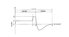
- the first passive motion control unit 67 controls the rotational speed of the first drive motor 11 so that the first drive motor 11 is driven at a predetermined first set speed V1 when performing the passive motion.
- the “passive movement” means that the arm 15 is rotated by the first drive motor 11 to bend, extend, palm-side adduction or palm-side abduction of the fingers of the trainee by an external force.
- the control by the first passive motion control unit 67 may be speed control based on a speed command, or may be position control in which the position command is sequentially changed so that the speed becomes the first set speed V1.
- the second passive motion control unit 69 controls the rotational speed of the first drive motor 11 so that the first drive motor 11 is driven at a predetermined second set speed V2 when performing the passive motion. As shown in FIG. 15, the second set speed V2 is set higher than the first set speed V1 in order to excite the human body reaction of the fingers (for example, stretch reflex, tendon, muscle spring, etc.).
- the control by the second passive motion control unit 69 may be speed control based on a speed command, or may be position control in which the position command is sequentially changed so that the speed becomes the second set speed V2.
- the first automatic motion control unit 71 gives a predetermined resistance force or assist force to each finger while canceling the reaction force due to the weight of the device or the like when performing the automatic motion, and the first drive motor 11 To control.
- “Automatic exercise” refers to turning the arm 15 in response to spontaneous flexion, extension, palmar adduction or palmar abduction by the trainee.
- the control by the first automatic motion control unit 71 is speed control based on the speed command Vref described later.
- the training type setting unit 73 sets the training type as "flexion” for training the flexion movement in the automatic movement, "extension” for training the extension movement in the automatic movement, and in the automatic movement.
- “Flexion extension” to train both flexion and extension movements "Palm side adduction” to train palm side adduction movement in automatic movement, “Palm side abduction” to train palm side abduction movement in automatic movement , Set to one of "palm side adduction” to train both palm side adduction movement and palm side abduction movement in automatic movement.
- the first control switching unit 75 changes the control switching mode according to the training type set by the training type setting unit 73. For example, when the training type is set to "flexion”, “extension”, “palm side adduction” or “palm side abduction", the first control switching unit 75 is the rotation position detected by the encoder 24. The control by the first passive motion control unit 67, the control by the second passive motion control unit 69, and the control by the first automatic motion control unit 71 are switched based on the above. As shown in FIG. 15, the first control switching unit 75 first executes control by the first passive motion control unit 67, and when the detection position reaches the first rotation position P1, the first passive motion control The control by the unit 67 is switched to the control by the second passive motion control unit 69.
- the control by the second passive motion control unit 69 is switched to the control by the first automatic motion control unit 71. Then, when the detection position reaches the third rotation position P3, the control by the first automatic motion control unit 71 is switched to the control by the first passive motion control unit 67 again. A predetermined number of cycles are repeated, with the combination of passive motion and automatic motion by executing the above three types of control as one cycle.
- the first control switching unit 75 controls the second passive motion based on the rotation position detected by the encoder 24.
- the control by the unit 69 and the control by the first automatic motion control unit 71 are switched.
- the first control switching unit 75 is first controlled by the second passive motion control unit 69 in either the flexion motion (palm side adduction motion) or the extension motion (palm side abduction). Is executed, and when the detection position reaches the fourth rotation position P4, the control by the second passive motion control unit 69 is switched to the control by the first automatic motion control unit 71.
- the control by the first automatic motion control unit 71 is switched to the control by the second passive motion control unit 69, and the flexion motion (palm side adduction motion) or extension is performed.
- the control by the second passive movement control unit 69 is executed.
- the control by the second passive motion control unit 69 is switched to the control by the first automatic motion control unit 71.
- the control by the first automatic motion control unit 71 is switched to the control by the second passive motion control unit 69 again.
- a predetermined number of cycles are repeated, with the combination of passive movement and automatic movement by executing two types of control in each of the above flexion movement (palm side adduction movement) and extension movement (palm side abduction) as one cycle. Is done.
- the first rotation speed calculation unit 77 calculates the rotation speed of the first drive motor 11 based on the detection result of the encoder 24. For example, the first rotation speed calculation unit 77 calculates the rotation speed by processing such as first-order differentiation of the position detected by the encoder 24 with time or counting the detection signal (for example, an incremental signal) for a predetermined time. ..
- the rotation speed corresponds to the rotation speed when the trainee voluntarily bends (palm-side adduction) or extends (palm-side abduction) the fingers.
- the first torque calculation unit 79 calculates the torque based on the rotation speed calculated by the first rotation speed calculation unit 77.
- the torque corresponds to the force when the trainee voluntarily bends the fingers (palm side adduction movement) or extension movement (palm side abduction).
- the torque may be calculated based on the measured value.
- the first speed command calculation unit 81 calculates the speed command Vref based on the rotation speed Vfb calculated by the first rotation speed calculation unit 77 and the torque Tfb calculated by the first torque calculation unit 79. Specifically, the first speed command calculation unit 81 calculates the speed command Vref based on the following calculation formula (1).
- the scan time is the time for the controller 7 to execute the processing during automatic movement (processing by the first automatic movement control unit 71) in one cycle, and is a fixed value determined based on the machine specifications.
- Virtual mass and virtual viscosity are parameters, and by these parameters, a predetermined resistance force (when the virtual viscosity coefficient is made positive) or assist force (when the virtual viscosity coefficient is made negative) is given to the fingers. It is possible to maintain muscle tension and improve the training effect.
- the first automatic motion control unit 71 controls the first drive motor 11 based on the speed command Vref calculated by the first speed command calculation unit 81 when performing automatic motion.
- the stimulus application processing unit 83 induces a human body reaction (for example, stretch reflex, tendon, muscle spring, etc.) of fingers when switching from control by the second passive movement control unit 69 to control by the first automatic movement control unit 71.
- the stimulus giving device 109 is controlled so as to give the stimulus to be given.
- the human body reaction is more likely to occur when switching from passive exercise to automatic exercise, and the effect of training can be further enhanced.
- the switching time referred to here does not necessarily have to coincide with the control switching timing. That is, at the time of switching, there is a time width straddling the control by the second passive motion control unit 69 and the control by the first automatic motion control unit 71, which can be felt as human reflexes at the same time. If the stimulus is given within, it corresponds to giving the stimulus at the time of switching.
- the stimulus applying device 109 is attached to the finger training device 1 and is a device that applies a predetermined stimulus that induces a human body reaction to a part related to the fingers.
- the device mode of the stimulus applying device 109 is not particularly limited, but for example, one or a plurality of electrical stimulators (electrode pads, etc.) or vibration generators attached near the muscles related to the movement of the finger to be trained. It can be configured as a device. In this case, the stimulus applying device 109 individually controls the voltage, frequency or vibration level of one or more electric stimulators or vibration generators to give a stimulus such as tapping the skin, or each electric stimulator.
- the skin muscle reflex can be induced by giving a stimulus that touches the skin by generating a stimulus by providing a time difference in each vibration generator.
- both electrical stimulation and vibration stimulation may be applied.
- it may be configured as a device for ejecting air from a nozzle, a device for operating the brush or a rod-shaped member so as to touch the skin.
- the first human body reaction amount calculation unit 85 is the human body of the fingers from the time when the control by the second passive motion control unit 69 is switched to the control by the first automatic motion control unit 71 until a predetermined time (for example, 100 ms) elapses.
- the human body reaction amount which is the amount (angle) of the arm 15 swiveling due to the reaction, is calculated based on the detection result of the encoder 24.
- the human body reaction amount calculated by the first human body reaction amount calculation unit 85 may be output as training result data in a predetermined file format (for example, CSV file or the like).
- the first display control unit 87 displays the human body reaction amount calculated by the first human body reaction amount calculation unit 85 on the touch panel 65 (see FIGS. 17 and 18 described later). During the training, the human body reaction amount is calculated for each cycle, and the display of the human body reaction amount is also updated for each cycle.
- the first range of motion measuring unit 89 measures the range of motion of the fingers by turning the arm 15 by the first drive motor 11. For example, when the first range of motion measuring unit 89 turns the arm 15 in each of the bending direction and the extending direction and the load torque of the first drive motor 11 (calculated by the first torque calculating unit 79) reaches a predetermined value.
- the rotation angle of is measured as the range of motion.
- the rotation angle when the measured value reaches a predetermined value may be measured as a range of motion.
- the first automatic momentum calculation unit 91 encodes an automatic momentum amount (angle) that is the amount (angle) that the trainee voluntarily turns the arm 15 during control by the first automatic movement control unit 71 (during automatic movement). It is calculated based on the detection results of 24. In addition, the first automatic momentum calculation unit 91 calculates the average value (average angle) of the automatic momentum from the start of training.
- the method for detecting the automatic momentum is not particularly limited, but for example, when the rotation speed calculated by the first rotation speed calculation unit 77 is equal to or less than a predetermined value, or when the rotation speed is equal to or less than the predetermined value for a predetermined time.
- the amount of rotation from the start of the automatic exercise to the time point may be used as the automatic exercise amount. Further, for example, when the measured value of the torque or force sensor 33 calculated by the first torque calculation unit 79 becomes a predetermined value or less, or when the state of being the predetermined value or less continues for a predetermined time or more, the training target. It may be determined that the voluntary automatic movement by the person has ended, and the amount of rotation from the start of the automatic movement to the time point may be used as the automatic movement amount.
- the first achievement rate calculation unit 93 is a ratio of the automatic momentum to the range of motion based on the automatic momentum calculated by the first automatic momentum calculation unit 91 and the range of motion measured by the first range of motion measurement unit 89. Calculate a certain automatic achievement rate (0 to 100%).
- the automatic achievement rate calculated by the first achievement rate calculation unit 93 can also be output as training result data in a predetermined file format (for example, a CSV file or the like).
- the second display control unit 95 displays the automatic achievement rate calculated by the first achievement rate calculation unit 93 and the average automatic momentum calculated by the first automatic momentum calculation unit 91 on the touch panel 65 (see the figure to be described later). 17, see FIG. 18).
- the automatic achievement rate and the average automatic exercise amount are calculated for each cycle, and the display of the automatic achievement rate and the average automatic exercise amount is also updated for each cycle.
- the first recording unit 97 rotates the arm 15 at a predetermined preparation speed (a speed slower than the first set speed V1) for the range of motion measured by the first range of motion measuring unit 89, and the brace 19 receives from the fingertip portion.
- a pre-measured value (an example of the first measured value) of the force (calculated by the first torque calculation unit 79) is recorded. If the force sensor 33 is provided instead of the torque calculated by the first torque calculation unit 79, the measured value may be recorded.
- the second recording unit 99 receives a force (first torque) from the fingertip portion when the arm 15 is turned at a predetermined training speed during control by the first automatic movement control unit 71 (during automatic movement).
- the measured value during training (calculated by the calculation unit 79) (an example of the second measured value) is recorded. If the force sensor 33 is provided instead of the torque calculated by the first torque calculation unit 79, the measured value may be recorded.
- the first human body reaction force calculation unit 101 is based on the difference between the measured value during training recorded by the second recording unit 99 and the pre-measured value recorded by the first recording unit 97, and the human body reaction (for example, extension) of the finger is performed. Calculate the force due to reflexes, tendons, muscle springs, etc.).
- the third display control unit 103 causes the touch panel 65 to display the display content related to the human body reaction force calculated by the first human body reaction force calculation unit 101 (not shown).
- the display related to the human body reaction force is, for example, a display of the achievement rate with respect to the target value of the human body reaction force, a display of the result of whether or not the result has been achieved, and the like.
- the human reaction force is calculated on a cycle-by-cycle basis, and the display related to the human body reaction force is also updated on a cycle-by-cycle basis.
- the tapping execution unit 105 switches from a passive motion in which the arm 15 is rotated by the first drive motor 11 to move the fingers by an external force to an automatic motion in which the arm 15 is rotated in response to the spontaneous movement of the fingers by the trainee.
- the third drive motor 41 of the tapping mechanism 5 is controlled so as to execute tapping at the timing (the timing of switching from the control by the second passive motion control unit 69 to the control by the first automatic motion control unit 71).
- the timing setting unit 107 sets the timing for executing tapping based on, for example, the user's setting input by the touch panel 65.
- the user can arbitrarily set the tapping timing, so the timing can be set appropriately based on the situation of the training target person and the guidance content of the training instructor (for example, a physical therapist or an occupational therapist). By changing it, the effect of training can be further enhanced.
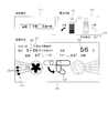
- FIG. 17 and 18 are explanatory views showing an example of the display of the touch panel 65 by the first display control unit 87 and the second display control unit 95.
- the contents displayed by the third display control unit 103 are not shown.
- the touch panel 65 displays a training type screen 111, an exercise state screen 113, and a training status screen 115.
- the training type screen 111 any of the above-mentioned "flexion”, “extension”, and “flexion extension” can be selected as the training type. In the example shown in FIG. 17, "bending" is selected.
- the second display control unit 95 displays the automatic achievement rate display unit 117 for each of the flexion movement and the extension movement, and also displays the average automatic momentum display unit 119.
- the automatic achievement rate display unit 117 corresponding to the flexion exercise is displayed, and the automatic achievement rate display unit 117 corresponding to the extension exercise is hidden ( Alternatively, it may be displayed lightly).
- the automatic achievement rate display unit 117 is composed of, for example, a plurality of meters, and the automatic achievement rate calculated by the first achievement rate calculation unit 93 is measured by lighting a number of meters corresponding to the magnitude of the value. Visualize.
- the automatic achievement rate display unit 117 lights a predetermined mark 121 (for example, a violet mark) located at the top of a plurality of meters. Let me. By displaying the automatic achievement rate with a meter or a mark in this way, the amount of voluntary movement by the trainee can be visualized in an easy-to-understand manner. Further, the average automatic momentum display unit 119 displays the average value of the automatic momentum from the start of training as an average angle (87 ° in this example).
- the human body reaction amount display unit 123 is displayed for each of the flexion movement and the extension movement by the first display control unit 87.
- the human body reaction amount display unit 123 corresponding to the flexion exercise is displayed, and the human body reaction amount display unit 123 corresponding to the extension exercise is not displayed ( Alternatively, it may be displayed lightly).
- the human body reaction amount display unit 123 visualizes the human body reaction amount calculated by the first human body reaction amount calculation unit 85 by displaying a number of marks 125 (for example, violet marks) corresponding to the magnitude of the value.
- the human body reaction amount when the human body reaction amount is 5 ° or less, there are 0 marks 125, and when the human body reaction amount is within the range of 6 ° to 11 °, there is one mark 125, and the human body reaction amount is 12 ° to 17 °.
- the range is within the range of 2 marks 125
- when the human body reaction amount is within the range of 24 ° to 29 °. 4 marks 125 are displayed, and 5 marks 125 are displayed when the human body reaction amount is 30 ° or more.
- the human body reaction amount is in the range of 18 ° to 23 °, and three marks 125 are displayed.
- the training status screen 115 shows the number of trainings 127, the remaining time 129, the number of cycles executed in this training 131, and the range of motion 133 in the bending direction measured by the first range of motion measuring unit 89.
- the range of motion 135 in the extension direction and the movement direction 137 indicating the direction in which the fingers should be moved in the automatic movement are displayed.
- FIG. 18 is an example of display when "extension" is selected as the training type.
- the automatic achievement rate display unit 117 corresponding to the extension exercise is displayed, and the automatic achievement rate display unit 117 corresponding to the flexion exercise is hidden (or may be a faint display). It has become.
- the automatic achievement rate is near the maximum value (value close to 100%), and the automatic achievement rate display unit 117 lights all the meters and the mark 121 located at the top.
- the human body reaction amount display unit 123 corresponding to the extension exercise is displayed, and the human body reaction amount display unit 123 corresponding to the flexion exercise is hidden (or may be displayed lightly).
- the human body reaction amount is in the range of 24 ° to 29 °, and four marks 125 are displayed.
- the above screen configuration is an example, and other items may be displayed in addition to or in place of the above-mentioned items, or a part of the above-mentioned items may be hidden. Further, the mark or symbol may be changed to another type, or the human body reaction amount or the automatic achievement rate may be displayed as a numerical value, for example.
- each processing unit of the controller 7 described above is not limited to the example of sharing these processing, and may be processed by, for example, a smaller number of processing units (for example, one processing unit). , It may be processed by a further subdivided processing unit.
- the controller 7 is implemented by an actual device only in a portion (inverter or the like) that supplies drive power to the first drive motor 11, and other functions are implemented by a program executed by the CPU 901 (see FIG. 45) described later.
- a part or all thereof may be implemented by an actual device such as an ASIC, an FPGA, or another electric circuit.
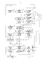
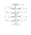
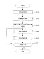
- step S10 in step S10, the controller 7 is rotated by the first drive motor 11 with the fingers to be trained attached to the brace 19 by the first range of motion measuring unit 89. Measure the range of motion of.
- step S20 the controller 7 uses the training type setting unit 73 to change the training type to "flexion”, “extension”, “flexion extension”, “palm side adduction”, based on the selection input of the training type on the touch panel 65. Set to either “palm side abduction” or “palm side adduction / abduction”.
- step S30 the controller 7 turns the arm 15 at a predetermined preparation speed based on the training type set in step S20 for the range of motion measured in step S10, and the device 19 is fingertiped by the first recording unit 97.
- a pre-measured value of the force received from the unit is recorded.
- step S100 the controller 7 executes the passive motion process.
- the contents of the passive motion processing will be described later (see FIG. 20).
- step S200 the controller 7 executes the automatic exercise process.
- the content of the automatic exercise processing will be described later (see FIG. 21).
- step S40 the controller 7 determines whether or not to end the training. Whether or not to end the training is determined by, for example, whether or not the set training time has elapsed, or whether or not the set number of cycles has been completed, and the like. If the training is not completed (step S40: NO), the process returns to step S100, and steps S100 and S200 are repeated until the training is completed. When the training is finished (step S40: YES), this flow is finished.
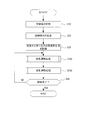
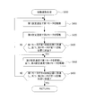
- FIG. 20 shows an example of the processing procedure of the passive motion processing in step S100. Note that FIG. 20 describes a case where the training type is set to any of “flexion”, “extension”, “palm side adduction”, and “palm side abduction” in step S20.
- step S110 the controller 7 uses the first passive motion control unit 67 to reduce the rotational speed of the first drive motor 11 so that the first drive motor 11 is driven at the first set speed V1. Control.
- step S120 the controller 7 determines whether or not the detection position by the encoder 24 has reached the first rotation position P1 by the first control switching unit 75. If the first rotation position P1 has not been reached (step S120: NO), the process returns to step S110. On the other hand, when the first rotation position P1 is reached (step S120: YES), the process proceeds to step S130.
- step S130 the controller 7 controls the rotation speed of the first drive motor 11 by the second passive motion control unit 69 so that the first drive motor 11 is driven at the second set speed V2.
- step S140 the controller 7 determines whether or not the detection position by the encoder 24 has reached the second rotation position P2 by the first control switching unit 75. If the second rotation position P2 has not been reached (step S140: NO), the process returns to step S130. On the other hand, when the second rotation position P2 is reached (step S140: YES), the passive motion process is terminated and the process proceeds to the automatic motion process in step S200.
- FIG. 21 shows an example of the processing procedure of the automatic movement processing in step S200. Note that FIG. 21 describes a case where the training type is set to any of “flexion”, “extension”, “palm side adduction”, and “palm side abduction” in step S20.
- step S205 the controller 7 is trained by the second recording unit 99 to receive the force (measured by the torque or force sensor 33 calculated by the first torque calculation unit 79) of the orthosis 19 from the fingertip portion. Start recording medium measurements.
- step S210 the controller 7 is switched from the control by the second passive motion control unit 69 to the control by the first automatic motion control unit 71 by the first human body reaction amount calculation unit 85, that is, the time when the automatic motion processing is started. It is determined whether or not a predetermined set time (waiting time for starting automatic exercise) has elapsed from. This step is repeated until the set time elapses (step S210: NO), and when the set time elapses (step S210: YES), the process proceeds to step S215.
- a predetermined set time waiting time for starting automatic exercise
- step S215 the controller 7 uses the first human body reaction amount calculation unit 85 to determine the amount by which the arm 15 is swiveled by the human body reaction of the fingers during the period from the start of the automatic exercise process to the elapse of a predetermined set time.
- the human body reaction amount (angle) is calculated based on the detection result of the encoder 24.
- the first display control unit 87 displays the calculated human body reaction amount on the touch panel 65.
- step S220 the controller 7 controls the speed of the first drive motor 11 based on the speed command Vref by the first automatic motion control unit 71.
- step S225 the controller 7 calculates the rotation speed of the first drive motor 11 based on the detection result of the encoder 24 by the first rotation speed calculation unit 77.
- step S230 the controller 7 calculates the torque by the first torque calculation unit 79 based on the rotation speed calculated in step S225. As described above, the torque may be calculated based on the measured value of the force sensor 33.
- step S235 the controller 7 calculates the speed command Vref by the first speed command calculation unit 81 based on the rotation speed calculated in step S225 and the torque calculated in step S230.
- step S240 the controller 7 determines whether or not the detection position by the encoder 24 has reached the third rotation position P3, or whether or not it has detected that the rotation speed calculated in step S225 is 0. .. If the third rotation position P3 has not been reached and the rotation speed is not 0 (step S240: NO), the process returns to the previous step S215. On the other hand, when the third rotation position P3 is reached or when it is detected that the rotation speed is 0 (step S240: YES), the process proceeds to step S245.
- step S245 the controller 7 calculates the automatic momentum, which is the amount (angle) of the trainee voluntarily turning the arm 15, by the first automatic momentum calculation unit 91, based on the detection result of the encoder 24. ..
- the first achievement rate calculation unit 93 calculates the automatic achievement rate, which is the ratio of the automatic momentum to the range of motion, based on the calculated automatic momentum and the range of motion measured in step S10.
- the second display control unit 95 causes the touch panel 65 to display the calculated automatic achievement rate.
- step S250 the controller 7 is the difference between the measured value during training recorded by the second recording unit 99 by the first human body reaction force calculation unit 101 and the pre-measured value recorded by the first recording unit 97 in step S30. Based on, the force due to the human body reaction of the fingers (for example, stretch reflex, tendon, muscle spring, etc.) is calculated. Then, the third display control unit 103 causes the touch panel 65 to display the display content related to the human body reaction force calculated by the first human body reaction force calculation unit 101. After that, the automatic movement process is finished, and the process proceeds to step S40 described above.
- step S100 and step S200 in FIG. 19 are repeated twice to complete one cycle.
- step S110 and step S120 are not executed, only step S130 and step S140 are executed, and in step S140, it is determined whether or not the fourth rotation position P4 or the sixth rotation position P6 has been reached. Further, in FIG. 21, in step S240, it is determined whether or not the fifth rotation position P5 or the seventh rotation position P7 has been reached.
- the finger training device 1 of the present embodiment includes a device 19 that holds the fingertip portion 63 of the finger 53, and an arm 15 that swivels around the swivel shaft 23 and moves the brace 19 around the swivel shaft 23.
- a planetary gear 17 that rotates in conjunction with the rotation of the arm 15 and rotates the brace 19 around a rotation shaft 25.
- the position of the fingertip portion 63 can be defined by the turning motion of the arm 15, and the angle of the fingertip portion 63 can be defined by the rotational motion of the planetary gear 17.
- the trajectory of the fingertip portion 63 can be defined, so that the movement of the finger 53 can be defined with a simple structure in which the arm 15 and the planetary gear 17 are interlocked.
- the finger training device 1 further has a fixed gear 13 fixedly arranged at the position of the turning shaft 23, and the planetary gear 17 meshes with the fixed gear 13 and rotates while rotating. It is a planetary gear that revolves around 13 and has a rotating shaft 25 connected to it.
- the arm 15 has a swivel shaft 23 connected to one end and a rotating shaft 25 rotatably inserted to the other end.
- the planetary gear 17 is an elliptical gear.
- the rotational speed of the planetary gear 17 can be changed while the arm 15 is rotated at the same angular velocity.
- the angle change of the brace 19 fixed to the planetary gear 17 can also be changed, so that the orbit of the fingertip portion 63 held by the brace 19 can be made variable.
- the arm 15 has a turning start position at an angle position close to the angle position where the turning radius of the planetary gear 17 is the shortest and the angle position where the turning radius is the shortest. Turn towards.
- the rotation speed of the planetary gear 17 can be gradually changed from low speed to high speed. Therefore, the movement of slowly changing the angle of the fingertip portion 63 during extension / flexion of the finger 53 (the first joint 57 extends slower than the second joint 59 and the third joint 61 during extension, and the second joint during flexion One joint 57 can bend slower than the second joint 59 and the third joint 61).
- the arm 15 has an angle position close to the angle position where the turning radius of the planetary gear 17 is the shortest than the angle position where the turning radius is the longest, and is set to the angle position where the turning radius is the longest. Turn towards.
- the rotation speed of the planetary gear 17 can be gradually changed from high speed to low speed. Therefore, a movement that changes the angle of the fingertip portion 63 faster when the finger 53 is extended / flexed (the first joint 57 extends faster than the second joint 59 and the third joint 61 during extension, and the first joint 57 extends faster during flexion.
- One joint 57 can bend faster than the second joint 59 and the third joint 61).
- the finger training device 1 is configured so that the turning start position of the arm 15 can be switched to a position where the turning radius of the planetary gear 17 becomes a desired radius.
- the orthosis 19 has a moving mechanism 29 capable of moving the holding position of the fingertip portion 63 in the extending direction of the arm 15.
- the position of the orthosis 19 can be changed according to the training type and the physical disparity (finger length, thickness, etc.) of the trainee, and the fingertip portion 63 can be appropriately held.
- the first drive motor 11 that swivels the arm 15 around the swivel shaft 23, the controller 7 that controls the first drive motor 11, and the equipment 19 are moved from the fingertip portion 63. It further has a first torque calculation unit 79 (which may be a force sensor 33) for measuring the received force, and the controller 7 has a first torque calculation unit 79 (which may be a force sensor 33) when the arm 15 is turned at a predetermined preparation speed.
- the finger 53 has a force to return by tendons and muscles for each range of movement. This is recorded as a pre-measured value before the execution of the training, and by taking the difference between the pre-measured value during the training measured during the training and the pre-measured value, the force of the tendon or muscle to return is canceled. , The force due to the human body reaction (stretch reflex) can be calculated. As a result, it is possible to measure the human body reaction in detail, and it is possible to realize a training device that can understand the recovery state of the trainee in more detail.
- the device 19 or the rotating shaft 25 is provided with the force sensor 33 for measuring the force received by the device 19 from the fingertip portion 63, the following effects are obtained.
- the force in the approximately tangential direction with respect to the trajectory of the fingertip portion 63 can be measured, so that the force due to the voluntary movement of the trainee, the force due to the tendon or muscle, and the like can be accurately measured. Further, by performing impedance control using the measurement result, when the trainee performs automatic exercise, a predetermined resistance force or assist force is applied to each finger 53 while canceling the reaction force due to the weight of the device or the like. It is possible to maintain muscle tension and improve the training effect.
- the finger training device 1 is arranged on the rotation shaft 25, and is arranged on the first attachment / detachment portion 35 and the arm 15 at which the orthosis 19 can be attached / detached at a position where the fingers 53 can be extended or bent. Further, there is a second attachment / detachment portion 37 to which the orthosis 19 can be attached / detached at a position where the palm side abduction or the palm side adduction of the thumb 53 is possible.
- the finger training device 1 further has a tapping mechanism 5 for tapping the vicinity of the base position of the finger 53 when training the extension or flexion motion of the finger 53.
- a trainee whose fingers are paralyzed due to a cerebrovascular disease or the like is in a situation where it is difficult to extend. Therefore, by tapping the vicinity of the base of the finger of the training target before the extension movement, it becomes possible to make the training target person aware of the movement timing of the finger, and the effect of the training can be further enhanced.
- the finger training device 1 further has a third drive motor 41 for driving the tapping mechanism 5, and the controller 7 causes the arm 15 to be swiveled by the first drive motor 11 to exert an external force on the fingers 53.
- the tapping execution unit that controls the third drive motor 41 so as to execute tapping at the timing of switching from the passive movement to be exercised by the automatic movement to the automatic movement of turning the arm 15 in response to the spontaneous movement of the fingers 53 by the trainee. Has 105.
- the controller 7 has a timing setting unit 107 that sets the timing for executing tapping based on the user's setting input.
- the user can arbitrarily set the tapping timing, so the timing can be set appropriately based on the situation of the training target person and the guidance content of the training instructor (for example, a physical therapist or an occupational therapist). By changing it, the effect of training can be further enhanced.
- the training target person for example, a physical therapist or an occupational therapist.
- the finger training device 1 further includes a stimulus applying device 109 that applies a predetermined stimulus to a human body portion related to the movement of the finger 53, and a controller 7 that controls the stimulus applying device 109.
- the controller 7 is an automatic movement in which the arm 15 is swiveled by the first drive motor 11 to move the fingers 53 by an external force, and the arm 15 is swiveled in response to the spontaneous movement of the fingers 53 by the trainee.
- It has a stimulus application processing unit 83 that controls the stimulus application device 109 so as to apply the stimulus at the timing of switching to.
- the finger training device 1 further has an encoder 24 for detecting the rotational position of the first drive motor 11, and the controller 7 rotates the arm 15 by the first drive motor 11 to rotate the finger 53.
- the first passive motion control unit 67 that drives the first drive motor 11 at the first set speed V1 when the passive motion is performed by an external force, and the first drive motor 11 when the passive motion is performed.
- the second passive motion control unit 69 which is driven by the second set speed V2, which is faster than the first set speed V1, and the automatic motion of turning the arm 15 in response to the spontaneous motion of the fingers 53 by the trainee.
- the finger training device 1 further has a touch panel 65 for displaying training, and the controller 7 is controlled by the first control switching unit 75 by the second passive motion control unit 69.
- the human body reaction amount which is the amount by which the arm 15 is swiveled by the human body reaction of the fingers 53 from the time when the control is switched to the control by the automatic motion control unit 71 until a predetermined time elapses, is calculated based on the detection result of the encoder 24. It has a human body reaction amount calculation unit 85 and a first display control unit 87 that displays the human body reaction amount on the touch panel 65.
- the finger training device 1 is configured so that the axial direction of the rotating shaft 23 of the arm 15 and the rotating shaft 25 of the planetary gear 17 is substantially the vertical direction, but the present invention is not limited to this.
- the finger training device may be configured so that the swivel shaft 23 and the swivel shaft 25 are in a substantially horizontal direction.
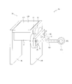
- FIG. 22 shows an example of the configuration of the finger movement mechanism 3A of the finger training device 1A according to this modified example.
- the same reference numerals are given to the same configurations as those in FIG. 1, and the description thereof will be omitted. Further, in FIG. 22, the tapping mechanism 5 and the support base for supporting the palm of the trainee are not shown.
- the finger operation mechanism 3A includes a gantry 139, a first drive motor 11, a fixed gear 13, an arm 15, a planetary gear 17, a support shaft 141, and an orthosis 143.
- the gantry 139 has a pair of side plates 145 and a top plate 147.
- the fixed gear 13 is fixedly arranged on the side surface of one side plate 145.
- a swivel shaft 23 is rotatably inserted into the fixed gear 13 in a substantially horizontal direction.
- the arm 15 is arranged on the side of the fixed gear 13 and swivels around the swivel shaft 23 (swivel shaft center AX1) to move the support shaft 141 and the brace 143 around the swivel shaft 23.
- a rotating shaft 25 (rotating axis AX2) is connected to the planetary gear 17 in a substantially horizontal direction.
- the planetary gear 17 is rotatably supported around the fixed gear 13 by the arm 15.
- the support shaft 141 is detachably connected to the rotating shaft 25 via the first attachment / detachment portion 35.
- an orthosis 143 for holding the fingertips of the trainee's fingers is provided.
- the brace 143 is formed in an annular shape in this example, and the fingertip portion of the finger to be trained is inserted through the brace 143.
- a force sensor may be provided inside the brace 143.
- a strain gauge for measuring the deflection of the support shaft 141 may be provided.
- both the fixed gear and the planetary gear 17 of the finger training device 1 are non-rotating center gears (gears whose swivel shaft and rotating shaft are offset from the gear center) has been described as an example.
- the gear mechanism is not limited to this.
- both the fixed gear and the planetary gear can be a rotation center gear (a gear in which the rotation shaft and the rotation shaft are in the gear center position).
- FIG. 23 shows an example of the operation of the gear mechanism of this modified example.
- the fixed gear 130 of this modified example is an elliptical spur gear (an example of a gear having a non-uniform radius).
- a swivel shaft 23 (swivel shaft center AX1) is rotatably inserted into the fixed gear 130 at the gear center position.
- the planetary gear 170 is a spur gear having the same shape as the fixed gear 130 and an elliptical number of teeth (an example of a gear having a non-uniform radius). The number of teeth of the fixed gear 130 and the planetary gear 170 may be different.
- a rotating shaft 25 (rotating axis AX2) is connected to the planetary gear 170 at the gear center position.
- the distance between the rotating shaft 25 (rotating shaft center AX2) and the swivel shaft 23 (swivel shaft center AX1) is constant with a radius r. That is, the rotating shaft 25 (rotating axis AX2) of the planetary gear 170 draws a circular locus with a radius r around the swirling shaft 23 (swivel axis AX1).
- FIG. 23 shows a state in which the planetary gear 170 is rotated (rotated) by 90 degrees around the rotating shaft 25 (rotating axis AX2).
- the planetary gear 170A one of the states in which the major axis of the planetary gear 170 is located on the same axis as the minor axis of the fixed gear 130 is referred to as the planetary gear 170A.
- a state in which the planetary gear 170A is rotated 90 degrees counterclockwise around the rotating shaft 25 (rotating axis AX2) is referred to as the planetary gear 170B.
- the planetary gear 170C is the state in which the planetary gear 170B is rotated 90 degrees in the counterclockwise direction, and the planetary gear 170D and the planetary gear 170D are in the counterclockwise direction when the planetary gear 170C is rotated 90 degrees in the counterclockwise direction.
- the planetary gear 170E is rotated 90 degrees
- the planetary gear 170E is rotated 90 degrees counterclockwise
- the planetary gear 170F
- the planetary gear 170F is rotated 90 degrees counterclockwise, the planetary gear 170G and the planetary gear.
- the state in which the 170G is rotated 90 degrees in the counterclockwise direction is referred to as the planetary gear 170H
- the state in which the planetary gear 170H is rotated 90 degrees in the counterclockwise direction is referred to as the planetary gear 170A.
- the radius of gyration of each of the planetary gears 170A, 170B, 170C, 170D, 170E, 170F, 170G, 170H is ra, rb, rc, rd, re, rf, rg, rh.
- the angular velocity of the planetary gear 170 can be changed while the arm 15 is rotated at the same angular velocity.
- the rotational speed (angle change) of the orthosis 19 fixed to the planetary gear 170 is also changed as desired depending on which range of the angle range shown in FIG. 23 is set for the turning range of the arm 15. ,
- the trajectory of the fingertip portion held by the brace 19 can be changed.
- the arm 15 is set at a position where the planetary gear 170 meshes with the fixed gear 130 near the long axis (planetary gears 170A, 170E) as a turning start position, and a position where the planetary gear 170 meshes with the fixed gear 130 near the short axis (planetary gear).
- the rotation speed of the planetary gear 170 can be gradually changed from low speed to high speed. Therefore, the movement of slowly changing the angle of the fingertip portion 63 during extension / flexion of the finger 53 (the first joint 57 extends slower than the second joint 59 and the third joint 61 during extension, and the second joint during flexion One joint 57 can bend slower than the second joint 59 and the third joint 61).
- the arm 15 is set at the position where the planetary gear 170 meshes with the fixed gear 130 near the short axis (planetary gears 170C, 170G) as the turning start position, and the position where the planetary gear 170 meshes with the fixed gear 130 near the long axis (the position where the planetary gear 170 meshes with the fixed gear 130 ().
- the rotation speed of the planetary gear 170 can be gradually changed from high speed to low speed.
- the fixed gear has a circular shape and the planetary gear has an elliptical shape has been described.
- the fixed gear may have an elliptical shape and the planetary gear may have a circular shape.
- at least one of the fixed gear and the planetary gear may be a gear having a non-uniform radius, and in the above first embodiment and the like.
- the elliptical shape described is an example, and other polygonal shapes such as a triangle and a quadrangle can be used.
- both the fixed gear 230 and the planetary gear 270 may be a rotation center gear and a circular gear. .. While the planetary gear 270 makes one revolution around the fixed gear 230, the distance between the rotating shaft 25 (rotating shaft center AX2) and the swivel shaft 23 (swivel shaft center AX1) is constant with a radius r. That is, the rotating shaft 25 (rotating axis AX2) of the planetary gear 270 draws a circular locus with a radius r around the swirling shaft 23 (swivel axis AX1).
- the rotational speed (angle change) of the equipment 19 is also constant, but by changing the turning angular velocity of the arm 15, the rotational speed (angle change) of the fixture 19 is desired. Changes may occur.
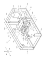
- FIG. 25 is a perspective view showing an example of the overall configuration of the finger training device according to the present embodiment
- FIG. 26 is an explanatory view showing an example of the operation of the gear mechanism.
- the directions such as up, down, left, right, front and back shown in FIG. 25 may be used as appropriate, but the positional relationship of each configuration of the finger training device is not limited.
- the finger training device 501 includes a frame 503, a finger movement mechanism 505, and a controller 507 (see FIG. 39 described later). Note that the controller 507 is not shown in FIG. 25.
- the frame 503 was bridged between a base frame 509 having a substantially rectangular frame shape, a plurality of (five in this example) support column frames 511a to 511e erected on the base frame 509, and support column frames 511a to 511e. It has a plurality of beam frames 513a to 513d (four in this example).
- the strut frame 511a is erected at the right front corner of the base frame 509
- the strut frame 511b is erected at the left-right intermediate position on the front side of the base frame 509
- the strut frame 511c is erected on the left front side of the base frame 509.
- the strut frame 511d is erected at the corner on the left rear side of the base frame 509, and the strut frame 511e is erected at the right rear corner of the base frame 509. Further, the beam frame 513d connects the upper part of the support frame 511d and the upper part of the support frame 511e, the beam frame 513a connects the upper part of the support frame 511a and the upper part of the support frame 511e, and the beam frame 513b connects the upper part of the support frame 511e.
- the upper part of the beam frame 513d is connected to the intermediate position in the left-right direction, and the beam frame 513c connects the upper part of the support column frame 511c and the upper part of the support column frame 511d. In FIG.
- the finger movement mechanism 505 includes a first finger movement mechanism 515 and a second finger movement mechanism 517.
- the first finger movement mechanism 515 mainly executes the extension and flexion movements of the first and second joints of the fingers
- the second finger movement mechanism 517 mainly executes the extension and flexion movements of the third joint of the fingers. To do.
- the first finger operation mechanism 515 includes a base 319, a first drive motor 521, a fixed gear 523, an arm 525, a planetary gear 527, a plurality of connecting members 529a to 529c, and an orthosis 531.
- the first drive motor 521 (an example of the first motor) is a rotary motor, and the arm 525 is swiveled around the swivel axis AX4 of the swivel shaft 533 (an example of the first swivel shaft).
- the first drive motor 521 is attached to the right side surface of the plate-shaped base 519, and is arranged sideways so that the rotation axis direction is along the left-right direction (horizontal direction).
- the output shaft of the first drive motor 521 is connected to the swivel shaft 533, and the swivel shaft 533 is connected to one end of the arm 525.
- the output shaft of the first drive motor 521 may be connected to the swivel shaft 533 via a speed reducer.
- the rotation position of the first drive motor 521 is detected by the encoder 524 (an example of the first rotation position sensor, see FIG. 39 described later).
- the first drive motor 521 is a servomotor whose position, speed, and torque are controlled by the controller 507 based on the detection result of the encoder 524.
- a rotation position sensor other than the encoder such as a resolver or a potentiometer, may be used.
- the fixed gear 523 is fixedly arranged on the left side surface of the base 519. That is, the fixed gear 523 is fixed so as not to rotate with respect to the base 519. As shown in FIG. 26, the fixed gear 523 is a circular spur gear. The number of teeth of the fixed gear 523 shown in FIG. 26 is an example, and is not limited to this.
- a swivel shaft 533 is rotatably inserted in the center position of the fixed gear 523 in the substantially left-right direction. The swivel shaft 533 is rotatably supported by a bearing (not shown) provided on the fixed gear 523.
- the arm 525 (an example of the first swivel member) is arranged on the left side of the fixed gear 523, swivels around the swivel shaft 533 (swivel shaft center AX4), and moves the brace 531 around the swivel shaft 533.
- a swivel shaft 533 is connected to the vicinity of one end of the arm 525.
- a rotating shaft 535 of the planetary gear 527 is rotatably inserted in the vicinity of the other end of the arm 525.
- the arm 525 rotatably supports the rotating shaft 535 at the other end.
- the planetary gear 527 (an example of a rotating member) rotates in conjunction with the rotation of the arm 525, and rotates the orthosis 531 around the rotation axis AX5 of the rotating shaft 535 via the connecting members 529a to 529c.
- the planetary gear 527 is a circular spur gear that meshes with the fixed gear 523 and revolves around the fixed gear 523 while rotating on its axis.
- the number of teeth of the planetary gear 527 is the same as that of the fixed gear 523, but the number of teeth may be different.
- a rotating shaft 535 is erected and connected to the center position of the planetary gear 527 in the substantially left-right direction.
- the rotary shaft 535 is rotatably supported by a bearing (not shown) provided on the arm 525.
- the planetary gear 527 is rotatably supported by an arm 525.
- the connecting members 529a to 529c are provided to arrange the orthosis 531 at an appropriate position so that the trainee can easily attach the fingertips of the fingers to the orthosis 531.
- the connecting member 529a is a rod-shaped member, and by connecting one end to the rotating shaft 535, the connecting member 529a rotates around the rotation axis AX5 of the rotating shaft 535 as the planetary gear 527 rotates.
- the connecting member 529b is a rod-shaped (for example, columnar) member, is arranged along the left-right direction (horizontal direction), and one end (right side) is connected to the other end of the connecting member 529a. ..
- the connecting member 529c is a rod-shaped member, and one end thereof is connected to the other end of the connecting member 529b.
- the brace 531 is rotatably provided around a rotation shaft 537 on the front side of the other end of the connecting member 529c.
- a support base 539 for supporting the palm of the trainee is installed on the base frame 509 so as to straddle the connecting member 529b in the front-rear direction.
- the trainee attaches the fingertips of the fingers to be trained to the orthosis 531 with the palm resting on the support base 539.
- the support base 539 is detachably installed with respect to the base frame 509, and the position of the support base 539 can be set, for example, depending on which of the left and right hands is to be trained and which finger is to be trained. It is possible to change it in the left-right direction, change the inclination, and replace it with another type of support.
- the orthosis 531 is, for example, a ring-shaped member, and holds the fingertips of the inserted fingers of the trainee.
- a flexible material such as rubber, resin, or urethane is provided inside the orthosis 531 and deforms according to the thickness and shape of the finger so that the fingertip portion can be appropriately held. Further, the orthosis 531 can rotate around the rotation shaft 537 as described above, and can hold the fingertip portion at an angle corresponding to the inclination of the fingertip portion.
- a force sensor 541 (an example of a measuring unit and a sensor; see FIG. 39 described later) for measuring the force received by the orthosis 531 from the fingertip portion may be provided inside the orthosis 531.
- the force sensor 541 the force in the tangential direction with respect to the trajectory of the fingertip can be measured, so that the force due to the voluntary movement of the trainee and the force to return by the tendon or muscle can be accurately measured. Can be measured.
- a strain gauge for measuring the deflection of the rotating shaft 535 may be provided instead of the force sensor.
- first finger motion mechanism 515 is an example, and configurations other than the above may be used.
- another connecting structure may be adopted instead of the connecting members 529a to 529c, or the brace 531 may be arranged on the arm 525 without providing the connecting members 529a to 529c.
- the second finger operation mechanism 517 includes a second drive motor 543, a worm gear 545, a coupling 547, a swivel shaft 549, a pair of support arms 551, and a pair of swivel arms 553.
- the second drive motor 543 (an example of the second motor) is a rotary motor, and the swivel arm 553 is swiveled around the swivel axis AX6 of the swivel shaft 549.
- the second drive motor 543 is fixed to an appropriate portion of the frame 503 (for example, the support column frame 511a or the beam frame 513a) by a fixing member (not shown), and is arranged vertically so that the rotation axis direction is substantially along the vertical direction. ing.
- the output shaft of the second drive motor 543 is connected to a worm gear 545 arranged below the second drive motor 543.
- the worm gear 545 changes the power transmission direction of the second drive motor 543 from the vertical direction to the horizontal direction, and reduces the rotation speed.
- the output shaft of the worm gear 545 is connected to the swivel shaft 549 via a coupling 547.
- the rotation position of the second drive motor 543 is detected by the encoder 555 (an example of the second rotation position sensor, see FIG. 39 described later).
- the second drive motor 543 is a servomotor whose position, speed, and torque are controlled by the controller 507 based on the detection result of the encoder 555.
- the first drive motor 521 and the second drive motor 543 are independently controlled by the controller 507.
- a rotation position sensor other than the encoder such as a resolver or a potentiometer, may be used.
- the swivel shaft 549 (an example of the second swivel shaft) is rotatably supported around the swivel shaft center AX6 by a pair of support arms 551 arranged at a predetermined distance in the left-right direction.
- the pair of support arms 551 are fixed to an appropriate portion of the frame 503 (for example, the support column frame 511b) via the base portion 557.
- a pair of swivel arms 553 (an example of a second swivel member) are connected to both ends of the base portion 559 in the longitudinal direction, and are arranged so as to face each other with a predetermined distance.
- the base portion 559 has a substantially center position in the longitudinal direction connected to the swivel shaft 549.
- the base portion 559 and the pair of swivel arms 553 swivel around the swivel axis AX6 as the swivel shaft 549 rotates.
- the pair of swivel arms 553 support the base 519 to which the first drive motor 521 and the like are attached so as to sandwich the base 519.
- the pair of swivel arms 553 moves the first finger operation mechanism 515 including the arm 525, the fixed gear 523, the planetary gear 527, the first drive motor 521, and the like around the swivel shaft 549 (swivel axis AX6). It is possible to make it.
- a groove 553a into which the base 519 is fitted is formed inside each of the pair of swivel arms 553, and the base 519 is moved along the extending direction of the swivel arm 553, for example, a screw (not shown). ) Etc. can be fixed at an appropriate position. As a result, the turning radius of the turning shaft 533 of the first finger operation mechanism 515 or the turning shaft 549 of the rotating shaft 535 can be adjusted.
- the configuration of the second finger motion mechanism 517 described above is an example, and a configuration other than the above may be used.
- the second drive motor 543 may be arranged sideways without providing the worm gear 545.
- the dimensions of the finger training device 501 in the left-right direction can be reduced.
- the fingers to be trained are used.
- a tapping mechanism for tapping the vicinity of the root position may be provided.
- the contact portion, arm, drive motor, etc. of the tapping mechanism may be installed on, for example, the swivel arm 553 or the like.
- the fixed gear 523 and the planetary gear 527 are both rotary center gears and circular spur gears. While the planetary gear 527 makes one revolution around the fixed gear 523, the distance between the rotating shaft 535 (rotating shaft center AX5) and the swivel shaft 533 (swivel shaft center AX4) is constant with a radius r. That is, the rotating shaft 535 (rotating axis AX5) of the planetary gear 527 draws a circular locus with a radius r around the swirling shaft 533 (swivel axis AX4).
- the rotation speed (angle change) of the equipment 531 is also constant, but by changing the turning angular velocity of the arm 525, the rotation speed (angle change) of the fitting 531 is changed. The desired change may occur.
- FIGS. 27 to 38 are explanatory views showing an example of bending / extending movements of fingers.
- the first joint 57, the second joint 59, the third joint 61, and the fingertip portion 63 of the fingers 53, palm 55, and fingers 53 are conceptually shown by broken lines. Further, the illustration of the finger movement mechanism 505 other than the brace 531 is omitted.
- FIGS. 27 to 29 flexion and extension of the first joint 57 (DIP joint) and the second joint 59 (PIP joint) of the four fingers (index finger, middle finger, ring finger, little finger) other than the mother finger are performed. An example of the case is shown.
- the operation is performed in the order of FIGS. 27, 28 and 29, the operation is to bend the fingers, and conversely, when the operations are performed in the order of FIGS. 29, 28 and 27, the operation is to extend the fingers.
- the arm 525 is swiveled around the swivel shaft 533 by the first drive motor 521 in a state where the fingertip portion 63 of the finger 53 is attached to the brace 531.
- the position of the fingertip portion 63 around the swivel shaft 533 is defined, the angle of the fingertip portion 63 is defined by the rotational movement of the planetary gear 527, and the first joint 57 and the second joint 59 are relatively greatly bent.
- the trajectory of the fingertip 63 is defined so as to extend.
- the second drive motor 543 is not driven, and the first finger operation mechanism 515 including the brace 531 is not swiveled around the swivel shaft 549.
- the third joint 61 flexes / extends relatively smaller than the first joint 57 and the second joint 59, or does not bend / extend.
- the flexion and extension movements of the first joint 57 and the second joint 59 are mainly performed.
- FIGS. 30 to 32 show an example in which the third joint 61 (MP joint) of the four fingers other than the thumb is mainly flexed and extended.
- the operation is to bend the fingers, and conversely, when operating in the order of FIGS. 32, 31 and 30, the operation is to extend the fingers.
- the first finger operation mechanism 515 including the brace 531 is swiveled around the swivel shaft 549 by the second drive motor 543 in a state where the fingertip portion 63 of the finger 53 is attached to the brace 531.
- the position and angle of the fingertip portion 63 around the swivel shaft 549 are defined, and the trajectory of the fingertip portion 63 is defined so that the third joint 61 performs a relatively large flexion / extension operation.
- the first drive motor 521 is not driven and the arm 525 is not swiveled around the swivel shaft 533.
- the first joint 57 and the second joint 59 perform flexion / extension movements relatively smaller than those of the third joint 61, or do not perform flexion / extension movements.
- the flexion and extension movements of the third joint 61 are mainly performed.
- FIGS. 33 to 35 flexion and flexion of all joints of the first joint 57 (DIP joint), the second joint 59 (PIP joint), and the third joint 61 (MP joint) of the four fingers other than the thumb.
- DIP joint first joint 57
- PIP joint second joint 59
- MP joint third joint 61
- the arm 525 is swiveled around the swivel shaft 533 by the first drive motor 521 in a state where the fingertip portion 63 of the finger 53 is attached to the brace 531.
- the position of the fingertip portion 63 around the swivel shaft 533 is defined, the angle of the fingertip portion 63 is defined by the rotational movement of the planetary gear 527, and the first joint 57 and the second joint 59 are relatively greatly bent.
- the trajectory of the fingertip 63 is defined so as to extend.
- the second drive motor 543 is not driven up to this point, and the first finger motion mechanism 515 including the brace 531 is not swiveled around the swivel shaft 549.
- the third joint 61 flexes / extends relatively smaller than the first joint 57 and the second joint 59, or does not bend / extend.
- the flexion and extension movements of the first joint 57 and the second joint 59 are mainly performed.
- the drive of the second drive motor 543 is started in parallel with the drive of the first drive motor 521, and the first finger operation mechanism 515 including the brace 531 is swiveled around the swivel shaft 549. ..
- the trajectory of the fingertip portion 63 is defined so that the third joint 61 flexes and extends along with the movements of the first joint 57 and the second joint 59.
- all the joints of the first joint 57, the second joint 59, and the third joint 61 are flexed and extended.
- the driving of the second driving motor 543 is started after the driving of the first driving motor 521, and the bending operation of the first joint 57 and the second joint 59 is started first, but the driving of each motor is started.
- the timing is not limited to the above.
- the driving of the first driving motor 521 may be started after the driving of the second driving motor 543, and the bending operation of the third joint 61 may be started first.
- the drive start timings of the first drive motor 521 and the second drive motor 543 are set to be substantially simultaneous, and all the joints of the first joint 57, the second joint 59, and the third joint 61 are flexed from the beginning. May be good.
- the drive of the first drive motor 521 is started after the drive of the second drive motor 543, the extension operation of the third joint 61 is started first, and then the first joint 57 is performed. And the extension operation of the second joint 59 is performed.
- the drive timing of each motor is not limited to the above.
- the drive of the second drive motor 543 may be started after the drive of the first drive motor 521, and the extension operation of the first joint 57 and the second joint 59 may be started first.
- the drive start timings of the first drive motor 521 and the second drive motor 543 are set to be substantially simultaneous, and all the joints of the first joint 57, the second joint 59, and the third joint 61 are extended from the beginning. May be good.
- FIGS. 36 to 38 when all the joints of the first joint 57 (IP joint), the second joint 59 (MP joint) and the third joint 61 (CM joint) of the thumb are flexed and extended. An example is shown.
- the operation is performed in the order of FIGS. 36, 37 and 38, the operation is to bend the fingers, and conversely, when the operations are performed in the order of FIGS. 38, 37 and 36, the operation is to extend the fingers.
- the arm 525 is swiveled around the swivel shaft 533 by the first drive motor 521 in a state where the fingertip portion 63 of the finger 53 is attached to the brace 531.
- the position of the fingertip portion 63 around the swivel shaft 533 is defined, the angle of the fingertip portion 63 is defined by the rotational movement of the planetary gear 527, and the first joint 57 and the second joint 59 are relatively greatly bent.
- the trajectory of the fingertip 63 is defined so as to extend.
- the second drive motor 543 is not driven up to this point, and the first finger motion mechanism 515 including the brace 531 is not swiveled around the swivel shaft 549.
- the third joint 61 flexes / extends relatively smaller than the first joint 57 and the second joint 59, or does not bend / extend.
- the flexion and extension movements of the first joint 57 and the second joint 59 are mainly performed.
- the drive of the second drive motor 543 is started in parallel with the drive of the first drive motor 521, and the first finger operation mechanism 515 including the brace 531 is swiveled around the swivel shaft 549. ..
- the trajectory of the fingertip portion 63 is defined so that the third joint 61 flexes and extends along with the movements of the first joint 57 and the second joint 59.
- all the joints of the first joint 57, the second joint 59, and the third joint 61 are flexed and extended.
- the drive of the second drive motor 543 is started after the drive of the first drive motor 521, but conversely, the drive of the first drive motor 521 may be started after the drive of the second drive motor 543. Good. Further, the drive start timings of the first drive motor 521 and the second drive motor 543 may be substantially simultaneous.
- the drive of the first drive motor 521 is started after the drive of the second drive motor 543, the extension operation of the third joint 61 is started first, and then the first joint 57 is performed. And the extension operation of the second joint 59 is performed.
- the drive of the second drive motor 543 may be started after the drive of the first drive motor 521.
- the drive start timings of the first drive motor 521 and the second drive motor 543 may be substantially simultaneous.
- the first drive motor 521 is mainly driven.
- the first joint 57 and the second joint 59 may be mainly flexed and extended, or the third joint 61 may be mainly flexed and extended by mainly driving the second drive motor 543. ..
- the finger training device 501 of the present embodiment also performs palm-side abduction or palm-side adduction of the thumb by attaching the brace 531 to the arm 525 at an appropriate position and posture. Is possible.
- FIGS. 39 to 41 are explanatory diagram showing an example of the functional configuration of the controller 507
- FIGS. 40 and 41 are explanatory views showing an example of a change in the rotation speed of the second drive motor 543.
- FIG. 39 the same functions as those in FIG. 14 will be omitted as appropriate.
- the controller 507 is configured as a computer equipped with a CPU, memory, and the like (see FIG. 45 described later).
- the controller 507 may be a controller dedicated to the finger training device 501, a general-purpose PC, or the like.
- the controller 507 includes a touch panel 561 (an example of a display unit) for performing a display related to training and various operations as an integral part or as a separate body.
- the touch panel 561 may be a simple liquid crystal display unit or the like that does not have a touch function.
- the controller 507 includes a first passive motion control unit 563, a second passive motion control unit 565, a first automatic motion control unit 567, a training type setting unit 569, and a first control.
- Unit 593 4th display control unit 595, 2nd movable range measurement unit 597, 2nd automatic momentum calculation unit 599, 2nd achievement rate calculation unit 601 and 5th display control unit 603, and 3rd recording. It has a unit 605, a fourth recording unit 607, a second human body reaction force calculation unit 609, and a sixth display control unit 611.
- the third passive motion control unit 579 controls the rotation speed of the second drive motor 543 so that the second drive motor 543 is driven at a predetermined third set speed V3 when performing the passive motion.
- Passive movement means that the first finger movement mechanism 515 including the orthosis 531 is rotated by the second drive motor 543, and the fingers of the trainee are bent, extended, palm-side adduction or palm-side abduction by an external force. It means to let.
- the control by the third passive motion control unit 579 may be speed control based on a speed command, or position control in which the position command is sequentially changed so that the speed becomes the third set speed V3.
- the third passive motion control unit 579 makes the drive start timing of the second drive motor 543 different from the drive start timing of the first drive motor 521 by the first passive motion control unit 563.
- the drive of the second drive motor 543 may be started after the drive of the first drive motor 521, or conversely, the drive of the first drive motor 521 may be started after the drive of the second drive motor 543. May be good.
- the drive start timings of both motors may be substantially the same.
- the third passive motion control unit 579 sets the third set speed V3 to the first setting of the first drive motor 521 in order to regulate the operation of the orthosis 531 so that the fingertip portion 63 of the finger draws a desired trajectory. Set the rotation speed different from the speed V1.
- the third set speed V3 may be set to a rotation speed substantially equal to the first set speed V1.
- the fourth passive motion control unit 581 controls the rotation speed of the second drive motor 543 so that the second drive motor 543 is driven at a predetermined fourth set speed V4 when performing the passive motion. As shown in FIG. 40, the fourth set speed V4 is set higher than the third set speed V3 in order to excite the human body reaction of the fingers (for example, stretch reflex, tendon, muscle spring, etc.).
- the control by the fourth passive motion control unit 581 may be speed control based on a speed command, or may be position control in which the position command is sequentially changed so that the speed becomes the fourth set speed V4.
- the fourth passive motion control unit 581 sets the fourth set speed V4 to the second setting of the first drive motor 521 in order to regulate the operation of the orthosis 531 so that the fingertip portion 63 of the finger draws a desired trajectory.
- the fourth set speed V4 may be set to a rotation speed substantially equal to the second set speed V2.
- the second automatic motion control unit 583 gives a predetermined resistance force or assist force to each finger while canceling the reaction force due to the weight of the device or the like when performing the automatic motion, and the second drive motor 543.
- the "automatic movement” means that the swivel arm 553 or the like (first finger movement mechanism 515) is swiveled in response to spontaneous flexion, extension, palmar adduction or palmar abduction by the trainee.
- the control by the second automatic motion control unit 583 is a speed control based on the speed command Vref described later.
- the second control switching unit 585 changes the control switching mode according to the training type set by the training type setting unit 569. For example, when the training type is set to "flexion”, “extension”, “palm side adduction” or “palm side abduction", the second control switching unit 585 is the rotation position detected by the encoder 555. Based on the above, the control by the third passive motion control unit 579, the control by the fourth passive motion control unit 581, and the control by the second automatic motion control unit 583 are switched. As shown in FIG.
- the second control switching unit 585 first executes control by the third passive motion control unit 579, and when the detection position reaches the eleventh rotation position P11, the third passive motion control The control by the unit 579 is switched to the control by the fourth passive motion control unit 581. Further, when the detection position reaches the twelfth rotation position P12, the control by the fourth passive motion control unit 581 is switched to the control by the second automatic motion control unit 583. Then, when the detection position reaches the thirteenth rotation position P13, the control by the second automatic motion control unit 583 is switched to the control by the third passive motion control unit 579 again. A predetermined number of cycles are repeated, with the combination of passive motion and automatic motion by executing the above three types of control as one cycle.
- the second control switching unit 585 controls the fourth passive motion based on the rotation position detected by the encoder 555.
- the control by the unit 581 and the control by the second automatic motion control unit 583 are switched.
- the second control switching unit 585 is first controlled by the fourth passive motion control unit 581 in either the flexion motion (palm side adduction motion) or the extension motion (palm side abduction). Is executed, and when the detection position reaches the 14th rotation position P14, the control by the fourth passive motion control unit 581 is switched to the control by the second automatic motion control unit 583.
- the control by the second automatic motion control unit 583 is switched to the control by the fourth passive motion control unit 581, and the flexion motion (palm side adduction motion) or extension is performed.
- the control by the fourth passive movement control unit 581 is executed.
- the control by the 4th passive motion control unit 581 is switched to the control by the 2nd automatic motion control unit 583.
- the control by the second automatic motion control unit 583 is switched to the control by the fourth passive motion control unit 581 again.
- a predetermined number of cycles are repeated, with the combination of passive movement and automatic movement by executing two types of control in each of the above flexion movement (palm side adduction movement) and extension movement (palm side abduction) as one cycle. Is done.
- the second rotation speed calculation unit 587 calculates the rotation speed of the second drive motor 543 based on the detection result of the encoder 555. For example, the second rotation speed calculation unit 587 calculates the rotation speed by processing such as first-order differentiation of the position detected by the encoder 555 with time or counting the detection signal (for example, an incremental signal) for a predetermined time. ..
- the rotation speed corresponds to the rotation speed when the trainee voluntarily bends (palm-side adduction) or extends (palm-side abduction) the fingers.
- the second torque calculation unit 589 calculates the torque based on the rotation speed calculated by the second rotation speed calculation unit 587.
- the torque corresponds to the force when the trainee voluntarily bends the fingers (palm side adduction movement) or extension movement (palm side abduction).
- the torque may be calculated based on the measured value.
- the second speed command calculation unit 591 uses the above calculation formula (1) based on the rotation speed Vfb calculated by the second rotation speed calculation unit 587 and the torque Tfb calculated by the second torque calculation unit 589.
- the speed command Vref is calculated based on this.
- the second automatic motion control unit 583 controls the second drive motor 543 based on the speed command Vref calculated by the second speed command calculation unit 591 when performing automatic motion.
- the second human body reaction amount calculation unit 593 is the human body of the fingers from the time when the control by the second passive motion control unit 565 is switched to the control by the first automatic motion control unit 567 until a predetermined time (for example, 100 ms) elapses.
- a predetermined time for example, 100 ms
- the human body reaction amount which is the total of the amount (angle) of the swivel arm 553 swiveled by the human body reaction of the fingers, is calculated based on the detection results of the encoder 524 and the encoder 555.
- the human body reaction amount is divided into the amount of rotation of the arm 525 (human body reaction amount of the first joint 57 and the second joint 59) and the amount of rotation of the swivel arm 553 (human body reaction amount of the third joint 61). It may be calculated.
- the human body reaction amount calculated by the second human body reaction amount calculation unit 593 may be output as training result data in a predetermined file format (for example, CSV file or the like).
- the fourth display control unit 595 displays the human body reaction amount calculated by the second human body reaction amount calculation unit 593 on the touch panel 561 (see FIGS. 17 and 18 described above).
- the human body reaction amount may be displayed separately as the human body reaction amount by the first joint 57 and the second joint 59 and the human body reaction amount by the third joint 61 (not shown).
- the human body reaction amount is calculated for each cycle, and the display of the human body reaction amount is also updated for each cycle.
- the second range of motion measuring unit 597 measures the range of motion of the fingers by turning the arm 525 by the first drive motor 521 and turning the swivel arm 553 by the second drive motor 543.
- the second movable range measuring unit 597 rotates the arm 525 and the swivel arm 553 in each of the bending direction and the extending direction, and the load torque of the first drive motor 521 (calculated by the first torque calculating unit 575) and the second.
- the rotation angle when the load torque of the drive motor 543 (calculated by the second torque calculation unit 589) reaches a predetermined value is measured as the movable range.
- Both the arm 525 and the swivel arm 553 may be swiveled, or only one of them may be swiveled. Further, the range of motion may be calculated separately for the range of motion of the first joint 57 and the second joint 59 and the range of motion of the third joint 61. Further, when the force sensor 541 is provided, the rotation angle when the measured value reaches a predetermined value may be measured as a range of motion.
- the trainee voluntarily at least one of the arm 525 and the swivel arm 553 during control by the first automatic movement control unit 567 and the second automatic movement control unit 583 (during automatic movement).
- the automatic momentum which is the amount (angle) of the swivel, is calculated based on the detection result of at least one of the encoder 524 and the encoder 555.
- the second automatic momentum calculation unit 599 calculates the average value (average angle) of the automatic momentum from the start of training.
- the method for detecting the automatic momentum is not particularly limited, but for example, when the rotation speed calculated by the first rotation speed calculation unit 573 and the second rotation speed calculation unit 587 is equal to or less than a predetermined value, or the predetermined value thereof.
- the state of being equal to or less than the value continues for a predetermined time or more, it may be determined that the voluntary automatic exercise by the trainee has ended, and the amount of rotation from the start of the automatic exercise to the time point may be used as the automatic exercise amount. Further, for example, when the torque calculated by the first torque calculation unit 575 and the torque calculated by the second torque calculation unit 589, or the measured value of the force sensor 541 becomes or less than a predetermined value, or less than or equal to the predetermined value.
- this state continues for a predetermined time or longer, it may be determined that the voluntary automatic exercise by the trainee has ended, and the amount of rotation from the start of the automatic exercise to that time point may be used as the automatic exercise amount.
- the automatic momentum and the average value of the automatic momentum are calculated separately for the average value of the automatic momentum and the automatic momentum by the first joint 57 and the second joint 59 and the average value of the automatic momentum and the automatic momentum by the third joint 61. You may.
- the second achievement rate calculation unit 601 is a ratio of the automatic momentum to the range of motion based on the automatic momentum calculated by the second automatic momentum calculation unit 599 and the range of motion measured by the second range of motion measurement unit 597. Calculate a certain automatic achievement rate (0 to 100%).
- the automatic achievement rate may be calculated separately for the automatic achievement rate by the first joint 57 and the second joint 59 and the automatic achievement rate by the third joint 61. Further, the automatic achievement rate calculated by the second achievement rate calculation unit 601 can be output as training result data in a predetermined file format (for example, CSV file or the like).
- the fifth display control unit 603 displays the automatic achievement rate calculated by the second achievement rate calculation unit 601 and the average automatic momentum calculated by the second automatic momentum calculation unit 599 on the touch panel 561 (the above-mentioned figure). 17, see FIG. 18). Even if the automatic achievement rate and the average automatic momentum are displayed separately for the automatic achievement rate and the average automatic momentum by the first joint 57 and the second joint 59, and the automatic achievement rate and the average automatic momentum by the third joint 61. Good (not shown). During the training, the automatic achievement rate and the average automatic momentum are calculated for each cycle, and the display of the automatic achievement rate and the average automatic momentum is also updated for each cycle.
- the third recording unit 605 rotates the arm 525 at a predetermined preparation speed (a speed slower than the first set speed V1) for the range of motion measured by the second range of motion measurement unit 597, and at the same time, a predetermined preparation speed (first).
- a predetermined preparation speed a speed slower than the first set speed V1
- first a predetermined preparation speed
- the swivel arm 553 is swiveled at a speed slower than the set speed V3), and the pre-measured value (third measurement) of the force (calculated by the first torque calculation unit 575 and the second torque calculation unit 589) received by the orthosis 531 from the fingertip portion. Record an example of the value).
- the pre-measured values are the pre-measured values by the first joint 57 and the second joint 59 (calculated by the first torque calculation unit 575) and the pre-measured values by the third joint 61 (calculated by the second torque calculation unit 589). It may be recorded separately. Further, both the arm 525 and the swivel arm 553 may be swiveled, or only one of them may be swiveled. Further, when the force sensor 541 is provided instead of the torque calculated by the first torque calculation unit 575 and the second torque calculation unit 589, the measured value may be recorded.
- the fourth recording unit 607 rotates the arm 525 and the swivel arm 553 at a predetermined training speed during control by the first automatic motion control unit 567 and the second automatic motion control unit 583 (during automatic motion).
- the measured value during training (an example of the fourth measured value) of the force received from the fingertip portion of the device 531 (calculated by the first torque calculation unit 575 and the second torque calculation unit 589) is recorded.
- the measured values during training are the measured values during training by the first joint 57 and the second joint 59 (calculated by the first torque calculation unit 575) and the measured values during training by the third joint 61 (second torque calculation unit 589). It may be recorded separately from (calculated by).
- both the arm 525 and the swivel arm 553 may be swiveled, or only one of them may be swiveled. Further, when the force sensor 541 is provided instead of the torque calculated by the first torque calculation unit 575 and the second torque calculation unit 589, the measured value may be recorded.
- the second human body reaction force calculation unit 609 is based on the difference between the measured value during training recorded by the third recording unit 605 and the pre-measured value recorded by the fourth recording unit 607, and the human body reaction (for example, extension) of the finger is performed. Calculate the force due to reflexes, tendons, muscle springs, etc.).
- the human body reaction force may be calculated separately for the human body reaction force by the first joint 57 and the second joint 59 and the human body reaction force by the third joint 61.
- the sixth display control unit 611 displays the display content related to the human body reaction force calculated by the second human body reaction force calculation unit 609 on the touch panel 561 (not shown).
- the display related to the human body reaction force is, for example, a display of the achievement rate with respect to the target value of the human body reaction force, a display of the result of whether or not the result has been achieved, and the like.
- the human reaction force is calculated on a cycle-by-cycle basis, and the display related to the human body reaction force is also updated on a cycle-by-cycle basis.
- the controller 507 is a stimulus applying processing unit, a tapping execution unit, and the like in the same manner as the controller 7 in the first embodiment described above. It may have a timing setting unit and the like.
- each processing unit of the controller 507 described above is not limited to the example of sharing these processing, and may be processed by, for example, a smaller number of processing units (for example, one processing unit). , It may be processed by a further subdivided processing unit. Further, the controller 507 is mounted by an actual device only for a portion (inverter or the like) that supplies drive power to the first drive motor 521 and the second drive motor 543, and other functions are executed by the CPU 901 (see FIG. 45) described later. It may be implemented by a program to be implemented, or a part or all thereof may be implemented by an actual device such as an ASIC, an FPGA, or another electric circuit.
- step S310 the controller 507 turns the arm 525 by the first drive motor 521 in a state where the second range of motion measuring unit 597 attaches the finger to be trained to the orthosis 531 and the arm 525 is rotated.
- the swivel arm 553 is swiveled by the two-drive motor 543 to measure the range of motion of the fingers.
- step S320 the controller 507 sets the training type to "flexion”, “extension”, “flexion extension”, “palm side adduction”, based on the selection input of the training type on the touch panel 561 by the training type setting unit 569. Set to either “palm side abduction” or “palm side adduction / abduction”.
- step S330 the controller 507 swivels the arm 525 and the swivel arm 553 at a predetermined preparatory speed based on the training type set in step S320 for the range of motion measured in step S310, and the third recording unit 605 determines.
- a pre-measured value of the force received by the orthosis 531 from the fingertip portion is recorded.
- step S400 the controller 507 executes the passive motion process.
- the content of the passive motion processing will be described later (see FIG. 43).
- step S500 the controller 507 executes the automatic exercise process.
- the content of the automatic exercise processing will be described later (see FIG. 44).
- step S340 the controller 507 determines whether or not to end the training. Whether or not to end the training is determined by, for example, whether or not the set training time has elapsed, or whether or not the set number of cycles has been completed, and the like. If the training is not completed (step S340: NO), the process returns to step S400, and steps S400 and S500 are repeated until the training is completed. When the training is finished (step S340: YES), this flow is finished.
- FIG. 43 shows an example of the processing procedure of the passive motion processing in step S400. Note that FIG. 43 describes a case where the training type is set to any of “flexion”, “extension”, “palm side adduction”, and “palm side abduction” in step S320. Further, FIG. 43 describes a case where the second drive motor 543 is started to be driven after the first drive motor 521 is driven.
- step S410 the controller 507 uses the first passive motion control unit 563 to reduce the rotation speed of the first drive motor 521 so that the first drive motor 521 is driven at the first set speed V1. Control.
- step S420 the controller 507 controls the rotation speed of the second drive motor 543 by the third passive motion control unit 579 so that the second drive motor 543 is driven at the third set speed V3.
- step S430 in the controller 507, the detection position by the encoder 524 reaches the first rotation position P1 by the first control switching unit 571 and the second control switching unit 585, and the detection position by the encoder 555 is the eleventh rotation position. It is determined whether or not P11 has been reached. If either the first rotation position P1 or the eleventh rotation position P11 has not been reached (step S430: NO), the process returns to step S410. On the other hand, when both the first rotation position P1 and the eleventh rotation position P11 are reached (step S430: YES), the process proceeds to step S440.
- step S440 the controller 507 controls the rotation speed of the first drive motor 521 so that the first drive motor 521 is driven at the second set speed V2 by the second passive motion control unit 565, and the fourth and other devices.
- the dynamic motion control unit 581 controls the rotation speed of the second drive motor 543 so that the second drive motor 543 is driven at the fourth set speed V4.
- step S450 in the controller 507, the detection position by the encoder 524 reaches the second rotation position P2 by the first control switching unit 571 and the second control switching unit 585, and the detection position by the encoder 555 is the twelfth rotation position. It is determined whether or not P12 has been reached. If either the second rotation position P2 or the twelfth rotation position P12 has not been reached (step S450: NO), the process returns to step S440. On the other hand, when both the second rotation position P2 and the twelfth rotation position P12 are reached (step S450: YES), the passive motion process is terminated and the process proceeds to the automatic motion process in step S500.
- FIG. 44 shows an example of the processing procedure of the automatic movement processing in step S500. Note that FIG. 44 describes a case where the training type is set to any of "flexion”, “extension”, “palm side adduction”, and “palm side abduction” in step S320.
- step S505 the controller 507 receives a force (torque or force calculated by the first torque calculation unit 575 and the second torque calculation unit 589) of the orthosis 531 from the fingertip portion by the fourth recording unit 607.
- the recording of the measured value during the training of the sensor 541) is started.
- step S510 the controller 507 is switched from the control by the second passive motion control unit 565 to the control by the first automatic motion control unit 567 by the second human body reaction amount calculation unit 593, and the fourth passive motion. It is determined whether or not a predetermined set time (waiting time for starting automatic movement) has elapsed from the time when the control by the control unit 581 is switched to the control by the second automatic movement control unit 583, that is, the start time of the automatic movement processing. To do. This step is repeated until the set time elapses (step S510: NO), and when the set time elapses (step S510: YES), the process proceeds to step S515.
- a predetermined set time waiting time for starting automatic movement
- step S515 the controller 507 uses the second human body reaction amount calculation unit 593 to determine the amount by which the arm 525 is swiveled by the human body reaction of the fingers during the period from the start of the automatic exercise process to the elapse of a predetermined set time.
- the human body reaction amount which is the sum of the angle) and the amount (angle) of the swivel arm 553 swiveling, is calculated based on the detection results of the encoder 524 and the encoder 555.
- the fourth display control unit 595 displays the calculated human body reaction amount on the touch panel 561.
- step S520 the controller 507 controls the speed of the first drive motor 521 based on the speed command Vref by the first automatic motion control unit 567, and based on the speed command Vref by the second automatic motion control unit 583.
- the speed of the second drive motor 543 is controlled.
- step S525 the controller 507 calculates the rotation speed of the first drive motor 521 based on the detection result of the encoder 524 by the first rotation speed calculation unit 573, and the second rotation speed calculation unit 587 calculates the rotation speed of the encoder 555.
- the rotation speed of the second drive motor 543 is calculated based on the detection result.
- step S530 the controller 507 calculates the torque of the first drive motor 521 based on the rotation speed calculated in step S525 by the first torque calculation unit 575, and the second torque calculation unit 589 calculates the torque in step S525.
- the torque of the second drive motor 543 is calculated based on the rotation speed calculated in 1. As described above, the torque may be calculated based on the measured value of the force sensor 541.
- step S535 the controller 507 calculates the speed command Vref of the first drive motor 521 based on the rotation speed calculated in step S525 and the torque calculated in step S530 by the first speed command calculation unit 577.
- the second speed command calculation unit 591 calculates the speed command Vref of the second drive motor 543 based on the rotation speed calculated in step S525 and the torque calculated in step S530.
- step S540 the controller 507 calculates whether or not the detection position by the encoder 524 has reached the third rotation position P3 and the detection position by the encoder 555 has reached the thirteenth rotation position P13, or in step S525. It is determined whether or not it is detected that the rotational speeds of the first drive motor 521 and the second drive motor 543 are both 0. If the third rotation position P3 or the thirteenth rotation position P13 has not been reached and the rotation speed of the first drive motor 521 or the second drive motor 543 is not 0 (step S540: NO), the previous step. Return to S515.
- step S540 when it is detected that the third rotation position P3 and the thirteenth rotation position P13 are reached, or the rotation speeds of the first drive motor 521 and the second drive motor 543 are both 0 (step S540: YES), the process proceeds to step S545.
- step S545 the controller 507 uses the second automatic momentum calculation unit 599 to set the automatic momentum, which is the amount (angle) of the trainee voluntarily turning the arm 525 and the swivel arm 553, to the encoder 524 and the encoder 555. Calculate based on the detection result.
- the second achievement rate calculation unit 601 calculates the automatic achievement rate, which is the ratio of the automatic momentum to the range of motion, based on the calculated automatic momentum and the range of motion measured in step S310.
- the fifth display control unit 603 causes the touch panel 561 to display the calculated automatic achievement rate.
- step S550 the controller 507 differs between the measured value during training recorded by the fourth recording unit 607 by the second human body reaction force calculation unit 609 and the pre-measured value recorded by the third recording unit 605 in step S330. Based on, the force due to the human body reaction of the fingers (for example, stretch reflex, tendon, muscle spring, etc.) is calculated. Then, the sixth display control unit 611 causes the touch panel 561 to display the display content related to the human body reaction force calculated by the second human body reaction force calculation unit 609. After that, the automatic movement process is finished, and the process proceeds to step S340 described above.
- the force due to the human body reaction of the fingers for example, stretch reflex, tendon, muscle spring, etc.
- step S400 and step S500 in FIG. 42 are repeated twice to complete one cycle.
- steps S410 to S430 are not executed, only steps S440 and S450 are executed, and in step S450, the fourth rotation position P4 and the 14th rotation position P14, or the sixth rotation position P6 and the sixth rotation position P6 and the fourth rotation position P14. It is determined whether or not the 16th rotation position P16 has been reached. Further, in FIG. 44, in step S540, it is determined whether or not the fifth rotation position P5 and the fifteenth rotation position P15, or the seventh rotation position P7 and the seventeenth rotation position P17 have been reached.
- the driving timing of the second driving motor 543 is started after the driving of the first driving motor 521 in the passive motion processing has been described, but as described above, the driving timing of each motor is limited to the above. is not it.
- the order of steps S410 and S420 may be reversed in FIG. 43.
- steps S410 and S420 may be executed at the same time in FIG. 43.
- the finger training device 501 of the present embodiment includes a device 531 that holds the fingertip portion 63 of the finger, an arm 525 that turns around the swivel shaft 533 and moves the brace 531 around the swivel shaft 533.
- a first drive motor 521 that swivels the arm 525 around the swivel shaft 533, a swivel arm 553 that swivels around the swivel shaft 549 and moves the arm 525 and the first drive motor 521 around the swivel shaft 549, and a swivel arm 553. It has a second drive motor 543 that swivels around a swivel shaft 549.
- the position and angle of the fingertip portion 63 can be defined by rotating the arm 525 by the first drive motor 521, and the first finger operation mechanism 515 thereof is further added to the second drive motor 543 and the swivel arm 553.
- the first drive motor 521 mainly executes the extension and flexion operations of the first joint 57 and the second joint 59 of the fingers
- the second drive motor 543 mainly executes the third joint of the fingers. It is possible to divide the movements of each joint of the fingers into two motors 521 and 543, such as executing the extension and flexion movements of 61.
- a controller 507 that independently controls the first drive motor 521 and the second drive motor 543 is further provided, and the controller 507 is the first to train the extension or flexion movement of the fingers.
- the drive start timings of the 1-drive motor 521 and the 2nd drive motor 543 are different.
- the controller 507 makes the rotation speeds of the first drive motor 521 and the second drive motor 543 different when training the extension or flexion movement of the fingers.
- the shapes of the fixed gear and the planetary gear are not limited to a circular shape.
- at least one of the fixed gear and the planetary gear may be a gear having a non-uniform radius to cause a desired change in the rotational speed (angle change) of the fixture 531.
- the fixed gear may have a circular shape and the planetary gear may have an elliptical shape, and conversely, the fixed gear may have an elliptical shape and the planetary gear may have a circular shape.
- both the fixed gear and the planetary gear may have an elliptical shape.
- at least one of the fixed gear and the planetary gear may be a gear having a non-uniform radius. It is also possible to make a polygonal shape such as a quadrangle or a quadrangle.
- Controller hardware configuration example> Next, with reference to FIG. 45, a hardware configuration example of the controllers 7 and 507 that realizes each process implemented by the program executed by the CPU 901 described above will be described. In FIG. 45, the configuration related to the function of supplying drive power to the motors of the controllers 7 and 507 is appropriately omitted.
- the controllers 7 and 507 include, for example, a CPU 901, a ROM 903, a RAM 905, a dedicated integrated circuit 907 constructed for a specific application such as an ASIC or an FPGA, an input device 913, and an output device. It has a 915, a recording device 917, a drive 919, a connection port 921, and a communication device 923. These configurations are connected so that signals can be transmitted to each other via the bus 909 and the input / output interface 911.
- the program can be recorded in, for example, a recording device 917 such as a ROM 903, a RAM 905, or a hard disk.
- a recording device 917 such as a ROM 903, a RAM 905, or a hard disk.
- the program can also be temporarily or permanently recorded on, for example, a magnetic disk such as a flexible disk, an optical disk such as various CDs, MO disks, or DVDs, or a removable recording medium 925 such as a semiconductor memory. ..
- a recording medium 925 can also be provided as so-called package software.
- the program recorded on these recording media 925 may be read by the drive 919 and recorded on the recording device 917 via the input / output interface 911, the bus 909, or the like.
- the program can also be recorded on, for example, a download site, another computer, another recording device, etc. (not shown).
- the program is transferred via a network NW such as LAN or the Internet, and the communication device 923 receives the program. Then, the program received by the communication device 923 may be recorded in the recording device 917 via the input / output interface 911, the bus 909, or the like.
- the program can be recorded in an appropriate externally connected device 927, for example.
- the program may be transferred via the appropriate connection port 921 and recorded in the recording device 917 via the input / output interface 911, the bus 909, or the like.
- the CPU 901 executes various processes according to the program recorded in the recording device 917, thereby realizing each of the above-mentioned processes.
- the CPU 901 may directly read the program from the recording device 917 and execute it, or may execute it after loading it into the RAM 905 once. Further, for example, when the CPU 901 receives the program via the communication device 923, the drive 919, or the connection port 921, the CPU 901 may directly execute the received program without recording it in the recording device 917.
- the CPU 901 may perform various processes based on signals and information input from an input device 913 such as a mouse, keyboard, microphone (not shown), if necessary.
- an input device 913 such as a mouse, keyboard, microphone (not shown), if necessary.
- the CPU 901 may output the result of executing the above processing from an output device 915 such as a display device or an audio output device, and the CPU 901 may connect the processing result to the communication device 923 or the communication device 923 as needed. It may be transmitted via the port 921, or may be recorded on the recording device 917 or the recording medium 925.
- an output device 915 such as a display device or an audio output device
Landscapes
- Health & Medical Sciences (AREA)
- Life Sciences & Earth Sciences (AREA)
- Animal Behavior & Ethology (AREA)
- Physical Education & Sports Medicine (AREA)
- Veterinary Medicine (AREA)
- Public Health (AREA)
- General Health & Medical Sciences (AREA)
- Pathology (AREA)
- Heart & Thoracic Surgery (AREA)
- Medical Informatics (AREA)
- Molecular Biology (AREA)
- Surgery (AREA)
- Biomedical Technology (AREA)
- Engineering & Computer Science (AREA)
- Biophysics (AREA)
- Physics & Mathematics (AREA)
- Epidemiology (AREA)
- Pain & Pain Management (AREA)
- Rehabilitation Therapy (AREA)
- Rehabilitation Tools (AREA)
Abstract
【課題】簡素な構造で手指の動作を規定できる指訓練装置を提供する。 【解決手段】指訓練装置1は、手指53の指先部63を保持する装具19と、旋回軸23周りに旋回し、装具19を旋回軸23周りに移動させるアーム15と、旋回軸23の位置に固定して配置された固定歯車13と、固定歯車13に噛み合い、自転しつつ固定歯車13の周りを公転する、回転軸25が連結され装具19を回転軸25周りに回転させる遊星歯車17と、を有する。
Description
開示の実施形態は、指訓練装置に関する。
特許文献1には、片麻痺指機能回復訓練装置が記載されている。この片麻痺指機能回復訓練装置は、訓練対象者の指に他動的屈曲と自動的伸展を行わせるための指屈伸機構を有する。
手指は指ごとに複数の関節を有しており、その動作は複雑である。上記従来技術の片麻痺指機能回復訓練装置は、手指の動作を規定するために多数の回転機構やリンク機構を組み合わせて構成されている。このため、構造が複雑となるという課題があった。
本発明はこのような問題点に鑑みてなされたものであり、簡素な構造で手指の動作を規定できる指訓練装置を提供することを目的とする。
上記課題を解決するため、本発明の一の観点によれば、手指の運動機能を回復させるための訓練を行う指訓練装置であって、前記手指の指先部を保持する装具と、第1旋回軸周りに旋回し、前記装具を前記第1旋回軸周りに移動させる第1旋回部材と、前記第1旋回部材の旋回と連動して回転し、前記装具を回転軸周りに回転させる回転部材と、を有する指訓練装置が適用される。
また、上記課題を解決するため、本発明の別の観点によれば、手指の運動機能を回復させるための訓練を行う指訓練装置であって、前記手指の指先部を保持する装具と、第1旋回軸周りに旋回し、前記装具を前記第1旋回軸周りに移動させる第1旋回部材と、前記第1旋回部材を前記第1旋回軸周りに旋回させる第1モータと、第2旋回軸周りに旋回し、前記第1旋回部材及び前記第1モータを前記第2旋回軸周りに移動させる第2旋回部材と、前記第2旋回部材を前記第2旋回軸周りに旋回させる第2モータと、を有する、指訓練装置が適用される。
本発明の指訓練装置によれば、簡素な構造で手指の動作を規定できる。
以下、実施の形態について図面を参照しつつ説明する。
<1.第1実施形態>
(1-1.指訓練装置の構成)
まず、図1及び図2を参照しつつ、第1実施形態に係る指訓練装置の構成の一例について説明する。図1は本実施形態に係る指訓練装置の全体構成の一例を示す斜視図、図2は歯車機構の動作の一例を示す説明図である。
(1-1.指訓練装置の構成)
まず、図1及び図2を参照しつつ、第1実施形態に係る指訓練装置の構成の一例について説明する。図1は本実施形態に係る指訓練装置の全体構成の一例を示す斜視図、図2は歯車機構の動作の一例を示す説明図である。
指訓練装置1は、訓練対象者の手指の運動機能を回復させたり、手指の筋力を増強するための訓練を行う装置である。訓練対象者は、例えば脳卒中などの脳血管疾患や整形外科疾患等による運動機能障害を有する患者等である。
図1に示すように、指訓練装置1は、指動作機構3と、タッピング機構5と、コントローラ7(後述の図14参照)とを有する。指動作機構3とタッピング機構5とは隣接して配置されている。なお、図1ではコントローラ7の図示を省略している。
指動作機構3は、訓練対象者の手指に対して各種動作(屈曲、伸展、掌側外転、掌側内転)の訓練を行うための機構である。指動作機構3は、架台9と、第1駆動モータ11と、固定歯車13と、アーム15と、遊星歯車17と、装具19とを有する。なお、図1では固定歯車13と遊星歯車17の歯、及び、訓練対象者の手掌を支持する支持台等の図示を省略している。
架台9は、一対の脚部20と、台座部21とを有する。なお、脚部20は例えば4本脚構造とするなど一対以外の構造としてもよい。
第1駆動モータ11(第1モータの一例)は、回転型のモータであり、アーム15を旋回軸23(第1旋回軸の一例)の旋回軸心AX1周りに旋回させる。第1駆動モータ11は、台座部21の下部に取り付けられており、一対の脚部20の間に配置されている。第1駆動モータ11の出力軸は旋回軸23に連結され、当該旋回軸23がアーム15の一端に連結されている。なお、第1駆動モータ11の出力軸を減速機を介して旋回軸23に連結してもよい。第1駆動モータ11の回転位置は、エンコーダ24(回転位置センサの一例。後述の図14参照)により検出される。第1駆動モータ11は、コントローラ7により、エンコーダ24の検出結果に基づいて位置、速度及びトルクの少なくとも1つを制御されるサーボモータである。なお、例えばレゾルバやポテンショメータ等、エンコーダ以外の回転位置センサを用いてもよい。
固定歯車13は、台座部21の上部に固定して配置されている。つまり、固定歯車13は台座部21に対して回転しないように固定されている。図2に示すように、固定歯車13は円形状の平歯車である。なお、図2では固定歯車13の歯数が30である場合を一例として示しているが、歯数はこれに限定されるものではない。固定歯車13には、歯車中心O1から所定距離d1だけオフセットした位置に、旋回軸23が略上下方向に回転可能に挿通されている。旋回軸23は、固定歯車13に設けられた軸受(図示省略)により回転可能に支持されている。
アーム15(第1旋回部材の一例)は、固定歯車13の上部に配置され、旋回軸23(旋回軸心AX1)周りに旋回し、装具19を旋回軸23周りに移動させる。アーム15の一方側の端部近傍には旋回軸23が連結されている。また、アーム15の他方側の端部近傍には遊星歯車17の回転軸25が回転可能に挿通されている。アーム15は、他方側の下部に回転軸25を回転可能に支持している。
遊星歯車17(回転部材の一例)は、アーム15の旋回と連動して回転し、装具19を回転軸25の回転軸心AX2周りに回転させる。図2に示すように、遊星歯車17は楕円形状の平歯車(半径が不均一な歯車の一例)であり、固定歯車13に噛み合い、自転しつつ固定歯車13の周りを公転する。なお、図2では遊星歯車17の歯数が30である場合を一例として示しているが、歯数はこれに限定されるものではない。例えば、固定歯車13の歯数と遊星歯車17の歯数を異ならせてもよい。遊星歯車17には、歯車中心O2から長軸方向に所定距離d2だけオフセットした位置に、回転軸25が略上下方向に立設して連結されている。回転軸25は、アーム15に設けられた軸受(図示省略)により回転可能に支持されている。遊星歯車17は、アーム15により回転可能に吊り下げ支持されている。
装具19は、訓練対象者の手指の指先部を保持する。「指先部」とは、各指の第1関節より先端側の部分をいう。なお、本実施形態では、各指の先端から1番目の関節を第1関節、2番目の関節を第2関節、3番目の関節を第3関節という。つまり、母指の場合には第1関節はIP関節、第2関節はMP関節、第3関節はCM関節である。母指以外の四指(示指、中指、環指、小指)の場合には、第1関節はDIP関節、第2関節はPIP関節、第3関節はMP関節である。
装具19は、指先部を保持する一対の保持部27と、当該保持部27をアーム15の延設方向に移動可能な移動機構29とを有する。保持部27は、指先部を挟んで固定する。保持部27は、例えばゴム、樹脂、ウレタン等の柔軟な材料で構成されており、指の太さや形状に応じて変形し、指先部を適切に保持することができる。移動機構29は、例えばネジ31を緩めることにより保持部27の移動を許容し、所望の位置でネジ31を締めることにより保持部27を固定する。このような構成により、装具19は指先部の保持位置をアーム15の延設方向に所定の範囲で移動することが可能である。
なお、一対の保持部27の各々の内側に、装具19が指先部から受ける力を測定する力センサ33(測定部、センサの一例)をそれぞれ設けてもよい。図1は、力センサ33を設けた場合を図示している。力センサ33を設けた場合には、指先部の軌道に対して概略接線方向の力を測定できるので、訓練対象者の随意運動による力や、腱や筋肉による戻ろうとする力等を、精度良く測定できる。なお、力センサの代わりに、例えば回転軸25の撓みを測定するひずみゲージを設けてもよい。
また、アーム15には、装具19を着脱可能な第1着脱部35と第2着脱部37が設けられている。第1着脱部35は、アーム15の他方側の端部近傍に配置され、回転軸25の上部に連結されている。装具19は、第1着脱部35に装着されることにより、手指の伸展又は屈曲が可能な位置に配置される(後述の図3~図11参照)。なお、図1は、装具19が第1着脱部35に装着された状態を示している。また、第2着脱部37は、アーム15の延設方向中間位置に配置されている。装具19は、第2着脱部37に装着されることにより、母指の掌側外転又は掌側内転が可能な位置に配置される(後述の図12及び図13参照)。なお、第1着脱部35及び第2着脱部37の着脱方式は特に限定されるものではないが、例えばマグネットやネジによる着脱方式とすることが可能である。
タッピング機構5は、指動作機構3により手指の伸展又は屈曲の動作を訓練する際に、訓練対象の手指の付け根位置近傍をタッピングするための機構である。タッピング機構5は、架台39と、第3駆動モータ41と、アーム43と、接触部45とを有する。
架台39は、一対の脚部47と、台座部49とを有する。なお、脚部47は例えば4本脚構造とするなど一対以外の構造としてもよい。
第3駆動モータ41(第3モータの一例)は、回転型のモータであり、アーム43を旋回軸51の旋回軸心AX3周りに旋回させる。第3駆動モータ41は、台座部49の下部に取り付けられており、一対の脚部47の間に配置されている。第3駆動モータ41の出力軸は旋回軸51に連結され、当該旋回軸51がアーム43の一端に連結されている。なお、第3駆動モータ41の出力軸を減速機を介して旋回軸51に連結してもよい。第3駆動モータ41は、コントローラ7により制御される。
アーム43は、台座部49の上部に配置され、旋回軸51周りに旋回し、接触部45を旋回軸51(旋回軸心AX3)周りに移動させる。アーム43の一方側の端部近傍には旋回軸51が連結されている。また、アーム43の他方側の先端部43aは、中間部に設けられた屈曲部43bにより高さが調節されている。
接触部45は、例えば円柱形状に形成されており、アーム43の先端部43aに立設されている。接触部45は、例えばゴム、樹脂、ウレタン等の柔軟な材料で構成されており、第3駆動モータ41により訓練対象の手指の付け根位置近傍にタッピングするように接触する。タッピングにより、訓練対象者に指の動作タイミングを意識させることが可能となり、訓練の効果をより高めることができる。
(1-2.歯車機構によるアームの旋回動作及び装具の回転動作)
次に、図2及び図3~図13を参照しつつ、指訓練装置1の歯車機構によるアーム15の旋回動作及び装具19の回転動作の一例について説明する。図3~図13はアーム15の旋回動作及び装具19の回転動作を表す説明図である。
次に、図2及び図3~図13を参照しつつ、指訓練装置1の歯車機構によるアーム15の旋回動作及び装具19の回転動作の一例について説明する。図3~図13はアーム15の旋回動作及び装具19の回転動作を表す説明図である。
図2に、遊星歯車17が自転しつつ固定歯車13の周りを公転する様子を示す。図2に示すように、遊星歯車17が固定歯車13の周りを1周する間、回転軸25(回転軸心AX2)と旋回軸23(旋回軸心AX1)との距離は半径Rで一定である。つまり、遊星歯車17の回転軸25(回転軸心AX2)は、旋回軸23(旋回軸心AX1)を中心に半径Rの円の軌跡を描く。
図2では、遊星歯車17が回転軸25(回転軸心AX2)周りに90度ずつ回転(自転)した状態を示している。ここでは説明の便宜上、遊星歯車17が、回転軸25(回転軸心AX2)が長軸上において旋回軸23(旋回軸心AX1)との間に歯車中心O2を挟むように位置した状態を、遊星歯車17Aとする。また、遊星歯車17Aが、回転軸25(回転軸心AX2)周りに反時計回り方向に90度回転した状態を遊星歯車17Bとする。同様に、遊星歯車17Bが反時計回り方向に90度回転した状態を遊星歯車17C、遊星歯車17Cが反時計回り方向に90度回転した状態を遊星歯車17D、遊星歯車17Dが反時計回り方向に90度回転した状態を遊星歯車17E、遊星歯車17Eが反時計回り方向に90度回転した状態を遊星歯車17F、遊星歯車17Fが反時計回り方向に90度回転した状態を遊星歯車17G、遊星歯車17Gが反時計回り方向に90度回転した状態を遊星歯車17H、遊星歯車17Hが反時計回り方向に90度回転した状態を遊星歯車17Aとする。
遊星歯車17A,17B,17C,17D,17E,17F,17G,17Hのそれぞれにおける回転半径は、Ra,Rb,Rc,Rd,Re,Rf,Rg,Rhとなる。なお、ここでいう「回転半径」とは、回転軸25(回転軸心AX2)と旋回軸23(旋回軸心AX1)とを結ぶ直線上における、回転軸25(回転軸心AX2)から遊星歯車17と固定歯車13との接触位置までの距離のことをいう。各回転半径の大小関係は、Ra>Rb=Rh>Rc=Rg>Rd=Rf>Reである。そして、アーム15の旋回角速度を一定とした場合、遊星歯車17A~17Hのそれぞれにおける回転軸25(回転軸心AX2)の円周方向の速度Vも一定となることから、遊星歯車17の回転軸25(回転軸心AX2)周りの角速度ωは、回転半径Ra~Rhが小さいほど大きくなる。したがって、遊星歯車17A,17B,17C,17D,17E,17F,17G,17Hのそれぞれにおける角速度をωa,ωb,ωc,ωd,ωe,ωf,ωg,ωhとすると、大小関係は、ωe>ωd=ωf>ωc=ωg>ωb=ωh>ωaとなる。
このようにして、アーム15を同一角速度で旋回させながら、遊星歯車17の角速度を変化させることができる。その結果、アーム15の旋回範囲を図2に示す角度範囲のどの範囲に設定するかに応じて、遊星歯車17に固定された装具19の回転速度(角度変化)にも所望の変化を生じさせ、装具19に保持された指先部の軌道を可変にできる。
例えば、図3~図5に、アーム15を遊星歯車17A~17Cの角度範囲で旋回させる場合のアーム15の旋回動作及び装具19の回転動作の一例を示す。図3、図4及び図5の順に動作する場合は、手指(この例では示指、中指、環指、小指の四指)を屈曲させる動作となり、反対に図5、図4及び図3の順に動作する場合は、手指を伸展させる動作となる。前者の屈曲動作は、遊星歯車17の回転半径が最大の回転半径Raとなる位置(回転半径が最も短くなる角度位置よりも最も長くなる角度位置に近い角度位置の一例)を旋回開始位置とし、回転半径が最も短くなる角度位置(回転半径Reとなる位置)に向けて旋回する場合の一例である。また、後者の伸展動作は、遊星歯車17の回転半径が回転半径Rcとなる位置(回転半径が最も長くなる角度位置よりも最も短くなる角度位置に近い角度位置の一例)を旋回開始位置とし、回転半径が最も長くなる角度位置(回転半径Raとなる位置)に向けて旋回する場合の一例である。
なお、図3~図5では、説明の便宜上、手指53、手掌55、手指53が有する第1関節57、第2関節59、第3関節61及び指先部63を概念的に破線で示す。また、移動機構29等の図示を省略している。図3~図5に示すように、手指53は、第1関節57が概略回転軸25(回転軸心AX2)上に位置し、旋回軸23(旋回軸心AX1)が概略第2関節59と第3関節61との間に位置するように、移動機構29により適宜の位置に移動された装具19に装着される。前述のように、遊星歯車17A~17Cの角速度の大小関係はωc>ωb>ωaであることから、図3、図4及び図5の順に手指53を屈曲動作させる場合は、遊星歯車17の回転速度を低速から高速に徐々に変化させることができる。その結果、屈曲の際に指先部63の角度を遅く変化させる動き(第1関節57が第2関節59及び第3関節61よりも遅く曲がる動き)を実現できる。反対に、図5、図4及び図3の順に手指53を伸展動作させる場合は、遊星歯車17の回転速度を高速から低速に徐々に変化させることができる。その結果、伸展の際に指先部63の角度を早く変化させる動き(第1関節57が第2関節59及び第3関節61よりも速く伸びる動き)を実現できる。
次に、図6~図8に、アーム15を遊星歯車17E~17Gの角度範囲で旋回させる場合のアーム15の旋回動作及び装具19の回転動作の一例を示す。図6、図7及び図8の順に動作する場合は、手指(この例では示指、中指、環指、小指の四指)を屈曲させる動作となり、反対に図8、図7及び図6の順に動作する場合は、手指を伸展させる動作となる。前者の屈曲動作は、遊星歯車17の回転半径が最小の回転半径Reとなる位置(回転半径が最も長くなる角度位置よりも最も短くなる角度位置に近い角度位置の一例)を旋回開始位置とし、回転半径が最も長くなる角度位置(回転半径Raとなる位置)に向けて旋回する場合の一例である。また、後者の伸展動作は、遊星歯車17の回転半径が回転半径Rgとなる位置(回転半径が最も長くなる角度位置よりも最も短くなる角度位置に近い角度位置の一例)を旋回開始位置とし、回転半径が最も短くなる角度位置(回転半径Reとなる位置)に向けて旋回する場合の一例である。
図6~図8に示すように、手指53は、第1関節57が概略回転軸25(回転軸心AX2)上に位置し、旋回軸23(旋回軸心AX1)が概略第2関節59と第3関節61との間に位置するように、移動機構29により適宜の位置に移動された装具19に装着される。前述のように、遊星歯車17E~17Gの角速度の大小関係はωe>ωf>ωgであることから、図6、図7及び図8の順に手指53を屈曲動作させる場合は、遊星歯車17の回転速度を高速から低速に徐々に変化させることができる。その結果、屈曲の際に指先部63の角度を早く変化させる動き(第1関節57が第2関節59及び第3関節61よりも速く曲がる動き)を実現できる。反対に、図8、図7及び図6の順に手指53を伸展動作させる場合は、遊星歯車17の回転速度を低速から高速に徐々に変化させることができる。その結果、伸展の際に指先部63の角度を遅く変化させる動き(第1関節57が第2関節59及び第3関節61よりも遅く伸びる動き)を実現できる。
次に、図9~図11に、母指を対象として、アーム15を遊星歯車17E~17Gの角度範囲で旋回させる場合のアーム15の旋回動作及び装具19の回転動作の一例を示す。図9、図10及び図11の順に動作する場合は、母指を屈曲させる動作となり、反対に図11、図10及び図9の順に動作する場合は、母指を伸展させる動作となる。前者の屈曲動作は、遊星歯車17の回転半径が最小の回転半径Re(所定の半径の一例)となる位置を旋回開始位置とし、回転半径が回転半径Reよりも長くなる方向に向けて旋回する場合の一例である。また、後者の伸展動作は、遊星歯車17の回転半径が回転半径Rg(所定の半径の一例)となる位置を旋回開始位置とし、回転半径が回転半径Rgよりも短くなる方向に向けて旋回する場合の一例である。
図9~図11に示すように、母指53は、第1関節57が概略回転軸25(回転軸心AX2)上に位置し、旋回軸23(旋回軸心AX1)が概略第2関節59と第3関節61との間に位置するように、移動機構29により適宜の位置に移動された装具19に装着される。前述のように、遊星歯車17E~17Gの角速度の大小関係はωe>ωf>ωgであることから、図9、図10及び図11の順に母指53を屈曲動作させる場合は、遊星歯車17の回転速度を高速から低速に徐々に変化させることができる。その結果、屈曲の際に指先部63の角度を早く変化させる動き(第1関節57が第2関節59及び第3関節61よりも速く曲がる動き)を実現できる。反対に、図11、図10及び図9の順に母指53を伸展動作させる場合は、遊星歯車17の回転速度を低速から高速に徐々に変化させることができる。その結果、伸展の際に指先部63の角度を遅く変化させる動き(第1関節57が第2関節59及び第3関節61よりも遅く伸びる動き)を実現できる。なお、説明は省略するが、母指53に対しても、図3~図5と同様に、アーム15を遊星歯車17A~17Cの角度範囲で旋回させることも可能である。
次に、図12及び図13に、母指を対象として、掌側内転及び掌側外転をさせる場合を示す。この例では、例えばアーム15を遊星歯車17A~17Bの角度範囲で旋回させる場合のアーム15の旋回動作及び装具19の回転動作の一例を示す。図12及び図13の順に動作する場合は、母指を掌側外転させる動作となり、反対に図13及び図12の順に動作する場合は、母指を掌側内転させる動作となる。この場合、装具19は、第1着脱部35から取り外され、第2着脱部37に装着される。その結果、装具19は遊星歯車17と連動して回転せず、アーム15の旋回と共に旋回軸23(旋回軸心AX1)周りを旋回する。これにより、装具19はアーム15の長手方向中間位置に配置され、母指53は、母指の掌側外転又は掌側内転が可能なように、移動機構29により適宜の位置に移動された装具19に装着される。以上から、掌側内転及び掌側外転をさせる場合には、アーム15の旋回範囲を図2に示す角度範囲のどの範囲に設定するかに関わりなく、装具19の回転速度(角度変化)はアーム15の旋回と等しくなる。
なお、指動作機構3は、アーム15の旋回範囲(旋回開始位置及び旋回終了位置)を、遊星歯車17の回転半径が所望の半径となる位置(回転半径が最も短くなる角度位置よりも最も長くなる角度位置に近い角度位置や、回転半径が最も長くなる角度位置よりも最も短くなる角度位置に近い角度位置等)に切り替え可能に構成されている。この切り替えは、例えばアーム15や遊星歯車17を取り外して向きや位置を変更する等の物理的な作業により行われてもよいし、コントローラ7における信号処理によって行われてもよい。これにより、訓練対象者の訓練状況や回復状況に応じて指先部63の軌道を可変させることが可能となり、適切な訓練を実行することができる。
(1-3.コントローラの機能構成)
次に、図14~図18を参照しつつ、コントローラ7の機能構成の一例について説明する。図14はコントローラ7の機能構成の一例を表す説明図、図15及び図16は第1駆動モータ11の回転速度の変化の一例を表す説明図、図17及び図18はコントローラ7による表示の一例を表す説明図である。
次に、図14~図18を参照しつつ、コントローラ7の機能構成の一例について説明する。図14はコントローラ7の機能構成の一例を表す説明図、図15及び図16は第1駆動モータ11の回転速度の変化の一例を表す説明図、図17及び図18はコントローラ7による表示の一例を表す説明図である。
コントローラ7は、CPUやメモリ等を備えたコンピュータとして構成される(後述の図45参照)。コントローラ7は、指訓練装置1専用のコントローラでもよいし、汎用PC等でもよい。コントローラ7は、訓練に関する表示や各種操作を行うためのタッチパネル65(表示部の一例)を一体又は別体として備えている。なお、タッチパネル65はタッチ機能を有しない単なる液晶表示部等でもよい。
図14に示すように、コントローラ7は、第1他動運動制御部67と、第2他動運動制御部69と、第1自動運動制御部71と、訓練種別設定部73と、第1制御切替部75と、第1回転速度算出部77と、第1トルク算出部79と、第1速度指令算出部81と、刺激付与処理部83と、第1人体反応量算出部85と、第1表示制御部87と、第1可動域計測部89と、第1自動運動量算出部91と、第1達成率算出部93と、第2表示制御部95と、第1記録部97と、第2記録部99と、第1人体反応力算出部101と、第3表示制御部103と、タッピング実行部105と、タイミング設定部107とを有する。
第1他動運動制御部67は、他動運動を行う際に、第1駆動モータ11が所定の第1設定速度V1で駆動するように第1駆動モータ11の回転速度を制御する。「他動運動」とは、第1駆動モータ11によりアーム15を旋回させて、訓練対象者の手指を外力により屈曲、伸展、掌側内転又は掌側外転させることをいう。なお、第1他動運動制御部67による制御は、速度指令に基づく速度制御でもよいし、速度が第1設定速度V1となるように位置指令を順次変更する位置制御としてもよい。
第2他動運動制御部69は、他動運動を行う際に、第1駆動モータ11が所定の第2設定速度V2で駆動するように第1駆動モータ11の回転速度を制御する。図15に示すように、第2設定速度V2は、手指の人体反応(例えば伸張反射や腱、筋肉のバネ等)を励起させるために第1設定速度V1よりも高速に設定されている。なお、第2他動運動制御部69による制御は、速度指令に基づく速度制御でもよいし、速度が第2設定速度V2となるように位置指令を順次変更する位置制御としてもよい。
第1自動運動制御部71は、自動運動を行う際に、装置の重量等による反力をキャンセルしつつ各手指に対して所定の抵抗力又はアシスト力を付与するように、第1駆動モータ11を制御する。「自動運動」とは、訓練対象者による自発的な屈曲、伸展、掌側内転又は掌側外転を受けてアーム15を旋回させることをいう。第1自動運動制御部71による制御は、後述する速度指令Vrefに基づく速度制御である。
訓練種別設定部73は、タッチパネル65における訓練種別の選択入力に基づいて、訓練種別を、自動運動において屈曲運動を訓練する「屈曲」、自動運動において伸展運動を訓練する「伸展」、自動運動において屈曲運動と伸展運動の両方を訓練する「屈曲伸展」、自動運動において掌側内転運動を訓練する「掌側内転」、自動運動において掌側外転運動を訓練する「掌側外転」、自動運動において掌側内転運動と掌側外転運動の両方を訓練する「掌側内外転」のいずれかに設定する。
第1制御切替部75は、訓練種別設定部73により設定された訓練種別に応じて、制御の切り替え態様を変更する。例えば、訓練種別が「屈曲」、「伸展」、「掌側内転」又は「掌側外転」に設定された場合には、第1制御切替部75は、エンコーダ24により検出された回転位置に基づいて、第1他動運動制御部67による制御と、第2他動運動制御部69による制御と、第1自動運動制御部71による制御とを切り替える。図15に示すように、第1制御切替部75は、まず第1他動運動制御部67による制御を実行し、検出位置が第1回転位置P1に到達した際に、第1他動運動制御部67による制御を第2他動運動制御部69による制御に切り替える。また、検出位置が第2回転位置P2に到達した際に、第2他動運動制御部69による制御を第1自動運動制御部71による制御に切り替える。そして、検出位置が第3回転位置P3に到達した際に、第1自動運動制御部71による制御を再び第1他動運動制御部67による制御に切り替える。以上の3種類の制御の実行による他動運動と自動運動の組み合わせを1サイクルとして、所定の回数のサイクルが繰り返される。
一方、訓練種別が「屈曲伸展」又は「掌側内外転」に設定された場合には、第1制御切替部75は、エンコーダ24により検出された回転位置に基づいて、第2他動運動制御部69による制御と、第1自動運動制御部71による制御とを切り替える。図16に示すように、第1制御切替部75は、屈曲運動(掌側内転運動)又は伸展運動(掌側外転)のいずれか一方において、まず第2他動運動制御部69による制御を実行し、検出位置が第4回転位置P4に到達した際に、第2他動運動制御部69による制御を第1自動運動制御部71による制御に切り替える。また、検出位置が第5回転位置P5に到達した際に、第1自動運動制御部71による制御を第2他動運動制御部69による制御に切り替え、屈曲運動(掌側内転運動)又は伸展運動(掌側外転)の他方において、第2他動運動制御部69による制御を実行する。また、検出位置が第6回転位置P6に到達した際に、第2他動運動制御部69による制御を第1自動運動制御部71による制御に切り替える。そして、検出位置が第7回転位置P7に到達した際に、第1自動運動制御部71による制御を再び第2他動運動制御部69による制御に切り替える。以上の屈曲運動(掌側内転運動)及び伸展運動(掌側外転)のそれぞれにおける2種類の制御の実行による他動運動と自動運動の組み合わせを1サイクルとして、所定の回数のサイクルが繰り返される。
第1回転速度算出部77は、エンコーダ24の検出結果に基づいて第1駆動モータ11の回転速度を算出する。例えば、第1回転速度算出部77は、エンコーダ24で検出された位置を時間で1階微分したり、検出信号(例えばインクリメンタル信号)を所定の時間カウントするなどの処理により、回転速度を算出する。当該回転速度は、訓練対象者が自発的に手指を屈曲運動(掌側内転運動)又は伸展運動(掌側外転)させる際の回転速度に相当する。
第1トルク算出部79は、第1回転速度算出部77により算出された回転速度に基づいてトルクを算出する。当該トルクは、訓練対象者が自発的に手指を屈曲運動(掌側内転運動)又は伸展運動(掌側外転)させる際の力に相当する。なお、回転速度からトルクを算出する他にも、装具19に力センサ33を設ける場合にはその測定値に基づいてトルクを算出してもよい。
第1速度指令算出部81は、第1回転速度算出部77により算出された回転速度Vfbと、第1トルク算出部79により算出されたトルクTfbとに基づいて、速度指令Vrefを算出する。具体的には、第1速度指令算出部81は次の計算式(1)に基づいて速度指令Vrefを算出する。

なお、スキャン時間は1サイクルにおいてコントローラ7が自動運動時の処理(第1自動運動制御部71による処理)を実行する時間であり、機械諸元に基づき決定される固定値である。仮想マス及び仮想粘性はパラメータであり、これらのパラメータにより、手指に対して所定の抵抗力(仮想粘性係数を正にする場合)又はアシスト力(仮想粘性係数を負にする場合)を付与することが可能となり、筋肉の緊張を維持させて訓練効果を向上することができる。
第1自動運動制御部71は、自動運動を行う際、第1速度指令算出部81により算出された速度指令Vrefに基づいて第1駆動モータ11を制御する。
刺激付与処理部83は、第2他動運動制御部69による制御から第1自動運動制御部71による制御への切り替え時に、手指の人体反応(例えば伸張反射や腱、筋肉のバネ等)を誘発する刺激を付与するように刺激付与装置109を制御する。これにより、他動運動から自動運動への切り替え時に人体反応がさらに生じ易くなり、訓練の効果をより高めることができる。なお、ここでいう切り替え時は、必ずしも制御の切り替えタイミングと同時である必要はない。すなわち、切り替え時は、人間の反射として同時と感じられる程度の、第2他動運動制御部69による制御及び第1自動運動制御部71による制御に跨る時間幅を有しており、その時間幅内で刺激が付与されれば、切り替え時に刺激を付与することに相当する。
刺激付与装置109は、指訓練装置1に付属され、手指に関連する部位に人体反応を誘発する所定の刺激を付与する装置である。刺激付与装置109の装置態様は特に限定されるものではないが、例えば訓練対象となる手指の動作に関連する筋肉部付近に貼り付けられる1又は複数の電気刺激装置(電極パッド等)又は振動発生装置として構成することができる。この場合、刺激付与装置109は、1又は複数の電気刺激装置又は振動発生装置の電圧、周波数又は振動レベルを個別に制御し、例えば皮膚をタッピングするような刺激を付与したり、各電気刺激装置又は各振動発生装置に時間差を設けて刺激を発生させることで皮膚をさするような刺激を付与することにより、皮膚筋反射を誘発することができる。また例えば、電気刺激と振動刺激の両方を付与してもよい。また、その他にも、例えばノズルからエアを噴出する装置や、刷毛や棒状の部材で皮膚をさするように動作させる装置等として構成してもよい。
第1人体反応量算出部85は、第2他動運動制御部69による制御から第1自動運動制御部71による制御へ切り替えた時点から所定時間(例えば100ms)経過するまでの間に手指の人体反応によりアーム15が旋回した量(角度)である人体反応量を、エンコーダ24の検出結果に基づいて算出する。なお、第1人体反応量算出部85により算出された人体反応量を、訓練結果データとして所定のファイル形式(例えばCSVファイル等)で出力可能としてもよい。
第1表示制御部87(第1表示制御部の一例)は、第1人体反応量算出部85により算出された人体反応量をタッチパネル65に表示させる(後述の図17、図18参照)。訓練の実行中は、人体反応量の算出がサイクルごとに行われ、人体反応量の表示もサイクルごとに更新される。
第1可動域計測部89は、第1駆動モータ11によりアーム15を旋回させて手指の可動域を計測する。例えば、第1可動域計測部89は、屈曲方向と伸展方向のそれぞれについてアーム15を旋回させ、第1駆動モータ11の負荷トルク(第1トルク算出部79により算出)が所定値に到達した際の回転角度を可動域として計測する。なお、力センサ33を設ける場合にはその測定値が所定値に到達した際の回転角度を可動域として計測してもよい。
第1自動運動量算出部91は、第1自動運動制御部71による制御時(自動運動時)に、訓練対象者が自発的にアーム15を旋回させた量(角度)である自動運動量を、エンコーダ24の検出結果に基づいて算出する。また、第1自動運動量算出部91は、訓練開始時からの自動運動量の平均値(平均角度)を算出する。自動運動量の検出手法は特に限定されるものではないが、例えば第1回転速度算出部77により算出された回転速度が所定値以下となった場合、あるいは、その所定値以下である状態が所定時間以上継続した場合に、訓練対象者による自発的な自動運動が終了したと判定し、自動運動開始から当該時点までの回転量を自動運動量としてもよい。また例えば、第1トルク算出部79により算出されたトルク又は力センサ33の測定値が所定値以下となった場合、あるいは、その所定値以下である状態が所定時間以上継続した場合に、訓練対象者による自発的な自動運動が終了したと判定し、自動運動開始から当該時点までの回転量を自動運動量としてもよい。
第1達成率算出部93は、第1自動運動量算出部91により算出された自動運動量と、第1可動域計測部89により計測された可動域とに基づいて、自動運動量の可動域に対する割合である自動達成率(0~100%)を算出する。なお、第1達成率算出部93により算出された自動達成率は、訓練結果データとして所定のファイル形式(例えばCSVファイル等)で出力することも可能である。
第2表示制御部95は、第1達成率算出部93により算出された自動達成率と、第1自動運動量算出部91により算出された平均自動運動量とを、タッチパネル65に表示させる(後述の図17、図18参照)。訓練の実行中は、自動達成率や平均自動運動量の算出がサイクルごとに行われ、自動達成率や平均自動運動量の表示もサイクルごとに更新される。
第1記録部97は、第1可動域計測部89により計測された可動域について所定の準備速度(第1設定速度V1よりも遅い速度)でアーム15を旋回させ、装具19が指先部から受ける力(第1トルク算出部79により算出)の事前測定値(第1測定値の一例)を記録する。なお、第1トルク算出部79により算出されたトルクの代わりに、力センサ33を設ける場合にはその測定値を記録してもよい。
第2記録部99は、第1自動運動制御部71による制御時(自動運動時)に、所定の訓練速度でアーム15を旋回させた際に、装具19が指先部から受ける力(第1トルク算出部79により算出)の訓練中測定値(第2測定値の一例)を記録する。なお、第1トルク算出部79により算出されたトルクの代わりに、力センサ33を設ける場合にはその測定値を記録してもよい。
第1人体反応力算出部101は、第2記録部99により記録された訓練中測定値と第1記録部97により記録された事前測定値との差分に基づいて、手指の人体反応(例えば伸張反射や腱、筋肉のバネ等)による力を算出する。
第3表示制御部103は、第1人体反応力算出部101により算出された人体反応力に関連する表示内容を、タッチパネル65に表示させる(図示省略)。人体反応力に関連する表示とは、例えば人体反応力の目標値に対する達成率の表示や、達成したか否かの結果表示等である。訓練の実行中は、人体反応力の算出がサイクルごとに行われ、人体反応力に関連する表示もサイクルごとに更新される。
タッピング実行部105は、第1駆動モータ11によりアーム15を旋回させて手指を外力により運動させる他動運動から訓練対象者による手指の自発的な運動を受けてアーム15を旋回させる自動運動に切り替わるタイミング(第2他動運動制御部69による制御から第1自動運動制御部71による制御へ切り替わるタイミング)で、タッピングを実行するようにタッピング機構5の第3駆動モータ41を制御する。
タイミング設定部107は、例えばタッチパネル65によるユーザの設定入力に基づいてタッピングを実行するタイミングを設定する。これにより、ユーザが任意にタッピングのタイミングを設定することができるので、訓練対象者の状況や訓練指導者(例えば理学療法士や作業療法士等)の指導内容等に基づいてタイミングを適宜設定・変更することで、訓練の効果をより高めることができる。
図17及び図18は、第1表示制御部87及び第2表示制御部95によるタッチパネル65の表示の一例を表す説明図である。なお、第3表示制御部103による表示内容については図示を省略する。図17に示すように、タッチパネル65には、訓練種別画面111と、運動状態画面113と、訓練状況画面115とが表示されている。訓練種別画面111では、訓練種別として、前述した「屈曲」、「伸展」、「屈曲伸展」のいずれかを選択することができる。図17に示す例では「屈曲」が選択されている。
運動状態画面113には、第2表示制御部95により、屈曲運動と伸展運動のそれぞれについて自動達成率表示部117が表示されると共に、平均自動運動量表示部119が表示される。図17に示す例では、訓練種別で「屈曲」が選択されているので、屈曲運動に対応する自動達成率表示部117が表示され、伸展運動に対応する自動達成率表示部117は非表示(あるいは薄い表示でもよい)となっている。自動達成率表示部117は、例えば複数のメータで構成されており、第1達成率算出部93により算出された自動達成率を、その値の大きさに応じた数のメータを点灯させることによって可視化する。また、自動達成率表示部117は、自動達成率が最大値近傍(100%に近い値)である場合には、複数のメータの最上部に位置する所定のマーク121(例えばスミレマーク)を点灯させる。このように自動達成率をメータやマークで表示することによって、訓練対象者が自発的に動かせた量を分かり易く可視化できる。また、平均自動運動量表示部119は、訓練開始時からの自動運動量の平均値を平均角度(この例では87°)として表示する。
訓練状況画面115には、第1表示制御部87により、屈曲運動と伸展運動のそれぞれについて人体反応量表示部123が表示される。図17に示す例では、訓練種別で「屈曲」が選択されているので、屈曲運動に対応する人体反応量表示部123が表示され、伸展運動に対応する人体反応量表示部123は非表示(あるいは薄い表示でもよい)となっている。人体反応量表示部123は、第1人体反応量算出部85により算出された人体反応量を、その値の大きさに応じた数のマーク125(例えばスミレマーク)を表示させることによって可視化する。例えば、人体反応量が5°以下の場合にはマーク125が0個、人体反応量が6°~11°の範囲内の場合にはマーク125が1個、人体反応量が12°~17°の範囲内の場合にはマーク125が2個、人体反応量が18°~23°の範囲内の場合にはマーク125が3個、人体反応量が24°~29°の範囲内の場合にはマーク125が4個、人体反応量が30°以上の場合にはマーク125が5個表示される。図17に示す例では、人体反応量が18°~23°の範囲内であり、マーク125が3個表示されている。このように人体反応量の大きさをマークの数で表示することによって、訓練対象者の人体反応の有無及びその大きさを分かり易く可視化できる。
また、訓練状況画面115には、人体反応量の他、訓練回数127、残り時間129、今回の訓練で実行したサイクル回数131、第1可動域計測部89によって計測された屈曲方向の可動域133及び伸展方向の可動域135、自動運動において手指を動かすべき方向を示す動作方向137が表示されている。
図18は、訓練種別として「伸展」が選択された場合の表示の一例である。図18に示すように、運動状態画面113において、伸展運動に対応する自動達成率表示部117が表示され、屈曲運動に対応する自動達成率表示部117は非表示(あるいは薄い表示でもよい)となっている。図18に示す例では、自動達成率が最大値近傍(100%に近い値)であり、自動達成率表示部117は全てのメータと最上部に位置するマーク121とを点灯させている。また、訓練状況画面115において、伸展運動に対応する人体反応量表示部123が表示され、屈曲運動に対応する人体反応量表示部123は非表示(あるいは薄い表示でもよい)となっている。図18に示す例では、人体反応量が24°~29°の範囲内であり、マーク125が4個表示されている。
なお、訓練種別で「屈曲伸展」が選択された場合には、上述した図17に示す表示内容と図18に示す表示内容とが、屈曲運動と伸展運動の切り替えに応じて交互に切り替わって表示される。
なお、上記画面構成は一例であり、上述した項目に加えて又は代えて、その他の項目を表示してもよいし、上述した項目の一部を非表示としてもよい。また、マークや記号を別の種類に変更してもよいし、人体反応量や自動達成率を例えば数値で表示してもよい。
なお、上述したコントローラ7の各処理部は、これらの処理の分担の例に限定されるものではなく、例えば、更に少ない数の処理部(例えば1つの処理部)で処理されてもよく、また、更に細分化された処理部により処理されてもよい。また、コントローラ7は、第1駆動モータ11に駆動電力を給電する部分(インバータ等)のみ実際の装置により実装され、その他の機能は後述するCPU901(図45参照)が実行するプログラムにより実装されてもよいし、その一部又は全部がASICやFPGA、その他の電気回路等の実際の装置により実装されてもよい。
(1-4.コントローラの処理手順)
次に、図19~図21を参照しつつ、コントローラ7のCPU901により実行される処理手順の一例について説明する。
次に、図19~図21を参照しつつ、コントローラ7のCPU901により実行される処理手順の一例について説明する。
図19に示すように、ステップS10では、コントローラ7は、第1可動域計測部89により、装具19に訓練対象の手指を装着させた状態で第1駆動モータ11によりアーム15を旋回させて手指の可動域を計測する。
ステップS20では、コントローラ7は、訓練種別設定部73により、タッチパネル65における訓練種別の選択入力に基づいて、訓練種別を「屈曲」、「伸展」、「屈曲伸展」、「掌側内転」、「掌側外転」、「掌側内外転」のいずれかに設定する。
ステップS30では、コントローラ7は、上記ステップS10で計測した可動域について、上記ステップS20で設定した訓練種別に基づいて所定の準備速度でアーム15を旋回させ、第1記録部97により装具19が指先部から受ける力の事前測定値(第1トルク算出部79により算出したトルク又は力センサ33で測定)を記録する。
ステップS100では、コントローラ7は、他動運動処理を実行する。他動運動処理の内容については後述する(図20参照)。
ステップS200では、コントローラ7は、自動運動処理を実行する。自動運動処理の内容については後述する(図21参照)。
ステップS40では、コントローラ7は、訓練を終了するか否かを判定する。訓練を終了するか否かは、例えば設定された訓練時間が経過したか否か、又は、設定された回数のサイクルが終了したか否か、等により判定される。訓練を終了しない場合には(ステップS40:NO)、上記ステップS100に戻り、訓練を終了するまでステップS100及びステップS200を繰り返す。訓練を終了する場合には(ステップS40:YES)、本フローを終了する。
図20に、上記ステップS100の他動運動処理の処理手順の一例を示す。なお、図20では、上記ステップS20において訓練種別が「屈曲」、「伸展」、「掌側内転」、「掌側外転」のいずれかに設定された場合について説明する。
図20に示すように、ステップS110では、コントローラ7は、第1他動運動制御部67により、第1駆動モータ11が第1設定速度V1で駆動するように第1駆動モータ11の回転速度を制御する。
ステップS120では、コントローラ7は、第1制御切替部75により、エンコーダ24による検出位置が第1回転位置P1に到達したか否かを判定する。第1回転位置P1に到達していない場合には(ステップS120:NO)、上記ステップS110に戻る。一方、第1回転位置P1に到達した場合には(ステップS120:YES)、ステップS130に移る。
ステップS130では、コントローラ7は、第2他動運動制御部69により、第1駆動モータ11が第2設定速度V2で駆動するように第1駆動モータ11の回転速度を制御する。
ステップS140では、コントローラ7は、第1制御切替部75により、エンコーダ24による検出位置が第2回転位置P2に到達したか否かを判定する。第2回転位置P2に到達していない場合には(ステップS140:NO)、上記ステップS130に戻る。一方、第2回転位置P2に到達した場合には(ステップS140:YES)、他動運動処理を終了し、ステップS200の自動運動処理に移る。
図21に、上記ステップS200の自動運動処理の処理手順の一例を示す。なお、図21では、上記ステップS20において訓練種別が「屈曲」、「伸展」、「掌側内転」、「掌側外転」のいずれかに設定された場合について説明する。
図21に示すように、ステップS205では、コントローラ7は、第2記録部99により、装具19が指先部から受ける力(第1トルク算出部79により算出したトルク又は力センサ33で測定)の訓練中測定値の記録を開始する。
ステップS210では、コントローラ7は、第1人体反応量算出部85により、第2他動運動制御部69による制御から第1自動運動制御部71による制御へ切り替えた時点、すなわち自動運動処理の開始時点から予め定められた設定時間(自動運動開始の待ち時間)が経過したか否かを判定する。設定時間が経過するまで本ステップを繰り返し(ステップS210:NO)、設定時間が経過した場合には(ステップS210:YES)、ステップS215に移る。
ステップS215では、コントローラ7は、第1人体反応量算出部85により、自動運動処理の開始時点から予め定められた設定時間が経過するまでの間に手指の人体反応によりアーム15が旋回した量(角度)である人体反応量を、エンコーダ24の検出結果に基づいて算出する。そして、第1表示制御部87により、算出した人体反応量をタッチパネル65に表示させる。
ステップS220では、コントローラ7は、第1自動運動制御部71により、速度指令Vrefに基づいて第1駆動モータ11の速度制御を行う。
ステップS225では、コントローラ7は、第1回転速度算出部77により、エンコーダ24の検出結果に基づいて第1駆動モータ11の回転速度を算出する。
ステップS230では、コントローラ7は、第1トルク算出部79により、上記ステップS225において算出した回転速度に基づいてトルクを算出する。なお、前述したように力センサ33の測定値に基づいてトルクを算出してもよい
ステップS235では、コントローラ7は、第1速度指令算出部81により、上記ステップS225において算出した回転速度と、上記ステップS230において算出したトルクとに基づいて、速度指令Vrefを算出する。
ステップS240では、コントローラ7は、エンコーダ24による検出位置が第3回転位置P3に到達したか否か、又は、上記ステップS225で算出した回転速度が0であることを検出したか否かを判定する。第3回転位置P3に到達しておらず、且つ、回転速度が0でない場合には(ステップS240:NO)、先のステップS215に戻る。一方、第3回転位置P3に到達したか、又は、回転速度が0であることを検出した場合には(ステップS240:YES)、ステップS245に移る。
ステップS245では、コントローラ7は、第1自動運動量算出部91により、訓練対象者が自発的にアーム15を旋回させた量(角度)である自動運動量を、エンコーダ24の検出結果に基づいて算出する。また、第1達成率算出部93により、算出した自動運動量と、上記ステップS10において計測した可動域とに基づいて、自動運動量の可動域に対する割合である自動達成率を算出する。さらに、第2表示制御部95により、算出した自動達成率をタッチパネル65に表示させる。
ステップS250では、コントローラ7は、第1人体反応力算出部101により、第2記録部99により記録した訓練中測定値と、上記ステップS30において第1記録部97により記録した事前測定値との差分に基づいて、手指の人体反応(例えば伸張反射や腱、筋肉のバネ等)による力を算出する。そして、第3表示制御部103により、第1人体反応力算出部101により算出した人体反応力に関連する表示内容を、タッチパネル65に表示させる。その後、自動運動処理を終了し、前述のステップS40に移る。
なお、以上では訓練種別が「屈曲」、「伸展」、「掌側内転」、「掌側外転」のいずれかに設定された場合について説明したが、訓練種別が「屈曲伸展」又は「掌側内外転」に設定された場合には、図19におけるステップS100及びステップS200が2回繰り返されることにより1サイクルとなる。この場合、図20において、ステップS110及びステップS120は実行せず、ステップS130及びステップS140のみ実行し、ステップS140では第4回転位置P4又は第6回転位置P6に到達したか否かを判定する。また、図21において、ステップS240では第5回転位置P5又は第7回転位置P7に到達したか否かを判定する。
また、前述の刺激付与処理部83による手指の人体反応を誘発する刺激を訓練対象者に付与する処理、及び、タッピング実行部105によりタッピング機構5を駆動させてタッピングを実行する処理は、上述したフローチャートとは異なる別のルーチンにて実行される。
(1-5.第1実施形態による効果)
以上説明したように、本実施形態の指訓練装置1は、手指53の指先部63を保持する装具19と、旋回軸23周りに旋回し、装具19を旋回軸23周りに移動させるアーム15と、アーム15の旋回と連動して回転し、装具19を回転軸25周りに回転させる遊星歯車17と、を有する。
以上説明したように、本実施形態の指訓練装置1は、手指53の指先部63を保持する装具19と、旋回軸23周りに旋回し、装具19を旋回軸23周りに移動させるアーム15と、アーム15の旋回と連動して回転し、装具19を回転軸25周りに回転させる遊星歯車17と、を有する。
これにより、アーム15の旋回動作により指先部63の位置を規定することができ、遊星歯車17の回転動作により指先部63の角度を規定することができる。これにより、指先部63の軌道を規定することが可能となるので、アーム15と遊星歯車17とを連動させた簡素な構造で手指53の動作を規定できる。
また、本実施形態では特に、指訓練装置1は、旋回軸23の位置に固定して配置された固定歯車13をさらに有し、遊星歯車17は、固定歯車13に噛み合い、自転しつつ固定歯車13の周りを公転する、回転軸25が連結された遊星歯車であり、アーム15は、一端に旋回軸23が連結され、他端に回転軸25が回転可能に挿通されている。
このような構造により、アーム15が旋回軸23周りに旋回すると固定歯車13と噛み合った遊星歯車17が回転する。これにより、アーム15の旋回(装具19の旋回)と遊星歯車17の回転(装具19の回転)とを連動させた機構を実現できる。
また、本実施形態では特に、遊星歯車17は、楕円形状の歯車である。
これにより、アーム15を同一角速度で旋回させながら、遊星歯車17の回転速度を変化させることができる。その結果、遊星歯車17に固定された装具19の角度変化にも変化を生じさせることができるので、装具19に保持された指先部63の軌道を可変にすることができる。
また、本実施形態では特に、アーム15は、遊星歯車17の回転半径が最も短くなる角度位置よりも最も長くなる角度位置に近い角度位置を旋回開始位置とし、回転半径が最も短くなる角度位置に向けて旋回する。
これにより、遊星歯車17の回転速度を低速から高速に徐々に変化させることができる。したがって、手指53の伸展・屈曲の際に指先部63の角度を遅く変化させる動き(伸展の際に第1関節57が第2関節59及び第3関節61よりも遅く伸び、屈曲の際に第1関節57が第2関節59及び第3関節61よりも遅く曲がる動き)を実現できる。
また、本実施形態では特に、アーム15は、遊星歯車17の回転半径が最も長くなる角度位置よりも最も短くなる角度位置に近い角度位置を旋回開始位置とし、回転半径が最も長くなる角度位置に向けて旋回する。
これにより、遊星歯車17の回転速度を高速から低速に徐々に変化させることができる。したがって、手指53の伸展・屈曲の際に指先部63の角度を早く変化させる動き(伸展の際に第1関節57が第2関節59及び第3関節61よりも速く伸び、屈曲の際に第1関節57が第2関節59及び第3関節61よりも速く曲がる動き)を実現できる。
また、本実施形態では特に、指訓練装置1は、アーム15の旋回開始位置を、遊星歯車17の回転半径が所望の半径となる位置に切り替え可能に構成されている。
これにより、訓練対象者の訓練状況や回復状況に応じて指先部63の軌道を可変させることが可能となり、適切な訓練を実行することができる。
また、本実施形態では特に、装具19は、指先部63の保持位置をアーム15の延設方向に移動可能な移動機構29を有する。
これにより、訓練種別や訓練対象者の体格差(手指の長さ、太さ等)に応じて装具19の位置を変更することができ、適切に指先部63を保持することができる。
また、本実施形態では特に、指訓練装置1は、アーム15を旋回軸23周りに旋回させる第1駆動モータ11と、第1駆動モータ11を制御するコントローラ7と、装具19が指先部63から受ける力を測定する第1トルク算出部79(力センサ33でもよい)と、をさらに有し、コントローラ7は、所定の準備速度でアーム15を旋回させた際に、第1トルク算出部79(力センサ33でもよい)で測定した事前測定値を記録する第1記録部97と、所定の訓練速度でアーム15を旋回させた際に、第1トルク算出部79(力センサ33でもよい)で測定した訓練中測定値を記録する第2記録部99と、訓練中測定値と事前測定値との差分に基づいて、手指53の人体反応による力を算出する第1人体反応力算出部101と、を有する。
手指53には、可動範囲ごとに腱や筋肉による戻ろうとする力が生じる。これを訓練の実行前に事前測定値として記録しておき、訓練中に測定した訓練中測定値と事前測定値との差分をとることにより、上記腱や筋肉による戻ろうとする力をキャンセルさせて、人体反応(伸張反射)による力を算出することができる。これにより、詳細な人体反応の測定が可能となり、訓練対象者の回復状態がより詳細に分かる訓練装置を実現できる。
また、本実施形態において、装具19又は回転軸25に、装具19が指先部63から受ける力を測定する力センサ33を設けた場合には、次のような効果を得る。
これにより、指先部63の軌道に対して概略接線方向の力を測定できるので、訓練対象者の随意運動による力や、腱や筋肉による戻ろうとする力等を、精度良く測定できる。また、当該測定結果を用いてインピーダンス制御を行うことにより、訓練対象者が自動運動を行う際に、装置の重量等による反力をキャンセルしつつ各手指53に対して所定の抵抗力又はアシスト力を付与し、筋肉の緊張を維持させて訓練効果を向上することが可能となる。
また、本実施形態では特に、指訓練装置1は、回転軸25に配置され、手指53の伸展又は屈曲が可能な位置に装具19を着脱可能な第1着脱部35と、アーム15に配置され、母指53の掌側外転又は掌側内転が可能な位置に装具19を着脱可能な第2着脱部37と、をさらに有する。
これにより、単体の訓練装置において、母指を含む5本の手指に対する伸展・屈曲動作と、母指に対する掌側外転・掌側内転動作を訓練することが可能となる。したがって、各手指の複雑な動作に対応できる訓練装置を実現できる。
また、本実施形態では特に、指訓練装置1は、手指53の伸展又は屈曲の動作を訓練する際に、手指53の付け根位置近傍をタッピングするタッピング機構5をさらに有する。
例えば脳血管疾患等により手指が麻痺した訓練対象者は、伸展動作がし難い状況になる。このため、伸展動作前に、訓練対象の手指の付け根付近をタッピングすることで、訓練対象者に指の動作タイミングを意識させることが可能となり、訓練の効果をより高めることができる。
また、本実施形態では特に、指訓練装置1は、タッピング機構5を駆動する第3駆動モータ41をさらに有し、コントローラ7は、第1駆動モータ11によりアーム15を旋回させて手指53を外力により運動させる他動運動から訓練対象者による手指53の自発的な運動を受けてアーム15を旋回させる自動運動に切り替わるタイミングで、タッピングを実行するように第3駆動モータ41を制御するタッピング実行部105を有する。
これにより、他動運動から自動運動への切り替え時に人体反応(例えば伸張反射等)を誘発することが可能となり、訓練の効果をより高めることができる。
また、本実施形態では特に、コントローラ7は、ユーザの設定入力に基づいてタッピングを実行するタイミングを設定するタイミング設定部107を有する。
これにより、ユーザが任意にタッピングのタイミングを設定することができるので、訓練対象者の状況や訓練指導者(例えば理学療法士や作業療法士等)の指導内容等に基づいてタイミングを適宜設定・変更することで、訓練の効果をより高めることができる。
また、本実施形態では特に、指訓練装置1は、手指53の動作に関連する人体部位に所定の刺激を付与する刺激付与装置109と、刺激付与装置109を制御するコントローラ7と、をさらに有し、コントローラ7は、第1駆動モータ11によりアーム15を旋回させて手指53を外力により運動させる他動運動から訓練対象者による手指53の自発的な運動を受けてアーム15を旋回させる自動運動に切り替わるタイミングで、刺激を付与するように刺激付与装置109を制御する刺激付与処理部83を有する。
これにより、他動運動から自動運動への切り替え時に、様々な刺激により人体反応(例えば伸張反射や腱、筋肉のバネ等)を誘発することが可能となり、訓練の効果をより高めることができる。
また、本実施形態では特に、指訓練装置1は、第1駆動モータ11の回転位置を検出するエンコーダ24をさらに有し、コントローラ7は、第1駆動モータ11によりアーム15を旋回させて手指53を外力により運動させる他動運動を行う際に、第1駆動モータ11を第1設定速度V1で駆動させる第1他動運動制御部67と、他動運動を行う際に、第1駆動モータ11を第1設定速度V1よりも高速の第2設定速度V2で駆動させる第2他動運動制御部69と、訓練対象者による手指53の自発的な運動を受けてアーム15を旋回させる自動運動を行う第1自動運動制御部71と、エンコーダ24により検出された回転位置に基づいて、第1他動運動制御部67による制御と、第2他動運動制御部69による制御と、第1自動運動制御部71による制御とを切り替える第1制御切替部75と、を有する。
このように、他動運動において自動運動への切り替え前に第1駆動モータ11が比較的高速な第2設定速度V2で駆動するように回転速度を制御することで、手指の人体反応(例えば伸張反射や腱、筋肉のバネ等)を励起させ、その後自動運動へ切り替えた際に訓練対象者の人体反応を利用して筋肉を刺激することが可能となり、運動機能を回復させる効果を高めることができる。
また、本実施形態では特に、指訓練装置1は、訓練に関する表示を行うタッチパネル65をさらに有し、コントローラ7は、第1制御切替部75により第2他動運動制御部69による制御から第1自動運動制御部71による制御へ切り替えた時点から所定時間経過するまでの間に手指53の人体反応によりアーム15が旋回した量である人体反応量を、エンコーダ24の検出結果に基づいて算出する第1人体反応量算出部85と、人体反応量をタッチパネル65に表示させる第1表示制御部87と、を有する。
これにより、人体反応の有無や人体反応量を可視化することができる。その結果、訓練対象者の訓練に対するモチベーションを向上できると共に、訓練指導者(例えば理学療法士や作業療法士等)が表示内容を活用することでより適切な訓練を行うことができる。
(1-6.変形例)
以上、添付図面を参照しながら第1実施の形態について詳細に説明した。しかしながら、特許請求の範囲に記載された技術的思想の範囲は、ここで説明した実施の形態に限定されるものではない。本実施形態の属する技術の分野における通常の知識を有する者であれば、技術的思想の範囲内において、様々な変更や修正、組み合わせなどを行うことに想到できることは明らかである。従って、これらの変更や修正、組み合わせなどが行われた後の技術も、当然に技術的思想の範囲に属するものである。
以上、添付図面を参照しながら第1実施の形態について詳細に説明した。しかしながら、特許請求の範囲に記載された技術的思想の範囲は、ここで説明した実施の形態に限定されるものではない。本実施形態の属する技術の分野における通常の知識を有する者であれば、技術的思想の範囲内において、様々な変更や修正、組み合わせなどを行うことに想到できることは明らかである。従って、これらの変更や修正、組み合わせなどが行われた後の技術も、当然に技術的思想の範囲に属するものである。
(1-6-1.旋回軸と回転軸の軸方向を水平方向とする場合)
上記第1実施形態では、アーム15の旋回軸23や遊星歯車17の回転軸25の軸方向が略上下方向となるように指訓練装置1を構成したが、これに限定されるものではない。例えば、旋回軸23や回転軸25が略水平方向となるように指訓練装置を構成してもよい。
上記第1実施形態では、アーム15の旋回軸23や遊星歯車17の回転軸25の軸方向が略上下方向となるように指訓練装置1を構成したが、これに限定されるものではない。例えば、旋回軸23や回転軸25が略水平方向となるように指訓練装置を構成してもよい。
図22に、本変形例に係る指訓練装置1Aの指動作機構3Aの構成の一例を示す。なお、図22において前述の図1と同様の構成には同符号を付し、説明を省略する。また、図22ではタッピング機構5及び訓練対象者の手掌を支持する支持台等の図示を省略している。
図22に示すように、指動作機構3Aは、架台139と、第1駆動モータ11と、固定歯車13と、アーム15と、遊星歯車17と、支持軸141と、装具143とを有する。架台139は、一対の側板145と、天板147とを有する。固定歯車13は、一方の側板145の側面に固定して配置されている。固定歯車13には、旋回軸23が略水平方向に回転可能に挿通されている。アーム15は、固定歯車13の側方に配置され、旋回軸23(旋回軸心AX1)周りに旋回し、支持軸141及び装具143を旋回軸23周りに移動させる。遊星歯車17には、回転軸25(回転軸心AX2)が略水平方向に連結されている。遊星歯車17は、アーム15により固定歯車13の周囲を回転可能に支持されている。
支持軸141は、第1着脱部35を介して回転軸25に着脱可能に連結されている。支持軸141の先端には、訓練対象者の手指の指先部を保持する装具143が設けられている。装具143は、この例では円環状に形成されており、訓練対象の手指の指先部が挿通される。図示は省略するが、装具143の内側に力センサを設けてもよい。また、力センサの代わりに、例えば支持軸141の撓みを測定するひずみゲージを設けてもよい。
本変形例の構成においても、上記第1実施形態と同様の効果を得ることができる。
(1-6-2.固定歯車と遊星歯車を回転中心歯車とする場合)
上記第1実施形態では、指訓練装置1の固定歯車13及び遊星歯車17の両方が共に非回転中心歯車(旋回軸や回転軸が歯車中心からオフセットした歯車)である場合を一例として説明したが、歯車機構はこれに限定されるものではない。例えば、固定歯車及び遊星歯車の両方を回転中心歯車(旋回軸や回転軸が歯車中心位置にある歯車)とすることも可能である。
上記第1実施形態では、指訓練装置1の固定歯車13及び遊星歯車17の両方が共に非回転中心歯車(旋回軸や回転軸が歯車中心からオフセットした歯車)である場合を一例として説明したが、歯車機構はこれに限定されるものではない。例えば、固定歯車及び遊星歯車の両方を回転中心歯車(旋回軸や回転軸が歯車中心位置にある歯車)とすることも可能である。
図23に、本変形例の歯車機構の動作の一例を示す。図23に示すように、本変形例の固定歯車130は、楕円形状の平歯車(半径が不均一な歯車の一例)である。固定歯車130には、歯車中心位置に、旋回軸23(旋回軸心AX1)が回転可能に挿通されている。遊星歯車170は、この例では固定歯車130と同じ形状、歯数の楕円形状の平歯車(半径が不均一な歯車の一例)である。なお、固定歯車130と遊星歯車170の歯数を異ならせてもよい。遊星歯車170には、歯車中心位置に、回転軸25(回転軸心AX2)が連結されている。
遊星歯車170が固定歯車130の周りを1周する間、回転軸25(回転軸心AX2)と旋回軸23(旋回軸心AX1)との距離は半径rで一定である。つまり、遊星歯車170の回転軸25(回転軸心AX2)は、旋回軸23(旋回軸心AX1)を中心に半径rの円の軌跡を描く。
図23では、遊星歯車170が回転軸25(回転軸心AX2)周りに90度ずつ回転(自転)した状態を示している。ここでは説明の便宜上、遊星歯車170の長軸が固定歯車130の短軸と同一軸上の位置した状態の一方を、遊星歯車170Aとする。また、遊星歯車170Aが、回転軸25(回転軸心AX2)周りに反時計回り方向に90度回転した状態を遊星歯車170Bとする。同様に、遊星歯車170Bが反時計回り方向に90度回転した状態を遊星歯車170C、遊星歯車170Cが反時計回り方向に90度回転した状態を遊星歯車170D、遊星歯車170Dが反時計回り方向に90度回転した状態を遊星歯車170E、遊星歯車170Eが反時計回り方向に90度回転した状態を遊星歯車170F、遊星歯車170Fが反時計回り方向に90度回転した状態を遊星歯車170G、遊星歯車170Gが反時計回り方向に90度回転した状態を遊星歯車170H、遊星歯車170Hが反時計回り方向に90度回転した状態を遊星歯車170Aとする。
遊星歯車170A,170B,170C,170D,170E,170F,170G,170Hのそれぞれにおける回転半径は、ra,rb,rc,rd,re,rf,rg,rhとなる。各回転半径の大小関係は、ra=re>rb=rd=rf=rh>rc=rgである。そして、アーム15の旋回角速度を一定とした場合、遊星歯車170A~170Hのそれぞれにおける回転軸25(回転軸心AX2)の円周方向の速度Vも一定となることから、遊星歯車170の回転軸25(回転軸心AX2)周りの角速度ωは、回転半径Ra~Rhが小さいほど大きくなる。したがって、遊星歯車170A,170B,170C,170D,170E,170F,170G,170Hのそれぞれにおける角速度をωa,ωb,ωc,ωd,ωe,ωf,ωg,ωhとすると、大小関係は、ωc=ωg>ωb=ωd=ωf=ωh>ωa=ωeとなる。
したがって、本変形例においても、アーム15を同一角速度で旋回させながら、遊星歯車170の角速度を変化させることができる。その結果、アーム15の旋回範囲を図23に示す角度範囲のどの範囲に設定するかに応じて、遊星歯車170に固定された装具19の回転速度(角度変化)にも所望の変化を生じさせ、装具19に保持された指先部の軌道を可変にできる。
例えば、アーム15を、遊星歯車170が長軸近傍で固定歯車130と噛み合う位置(遊星歯車170A,170E)を旋回開始位置とし、遊星歯車170が短軸近傍で固定歯車130と噛み合う位置(遊星歯車170C,170G)に向けて旋回させる場合、遊星歯車170の回転速度を低速から高速に徐々に変化させることができる。したがって、手指53の伸展・屈曲の際に指先部63の角度を遅く変化させる動き(伸展の際に第1関節57が第2関節59及び第3関節61よりも遅く伸び、屈曲の際に第1関節57が第2関節59及び第3関節61よりも遅く曲がる動き)を実現できる。
また反対に、アーム15を、遊星歯車170が短軸近傍で固定歯車130と噛み合う位置(遊星歯車170C,170G)を旋回開始位置とし、遊星歯車170が長軸近傍で固定歯車130と噛み合う位置(遊星歯車170A,170E)に向けて旋回させる場合、遊星歯車170の回転速度を高速から低速に徐々に変化させることができる。したがって、手指53の伸展・屈曲の際に指先部63の角度を早く変化させる動き(伸展の際に第1関節57が第2関節59及び第3関節61よりも速く伸び、屈曲の際に第1関節57が第2関節59及び第3関節61よりも速く曲がる動き)を実現できる。
(1-6-3.歯車形状のバリエーション)
上記第1実施形態では、固定歯車を円形状、遊星歯車を楕円形状とした場合について説明したが、反対に、固定歯車を楕円形状、遊星歯車を円形状としてもよい。また、装具19の回転速度(角度変化)に所望の変化を生じさせるためには、固定歯車又は遊星歯車の少なくとも一方を半径が不均一な歯車とすればよく、以上の第1実施形態等で説明した楕円形状は一例であり、その他にも例えば三角形や四角形等の多角形状とすることも可能である。
上記第1実施形態では、固定歯車を円形状、遊星歯車を楕円形状とした場合について説明したが、反対に、固定歯車を楕円形状、遊星歯車を円形状としてもよい。また、装具19の回転速度(角度変化)に所望の変化を生じさせるためには、固定歯車又は遊星歯車の少なくとも一方を半径が不均一な歯車とすればよく、以上の第1実施形態等で説明した楕円形状は一例であり、その他にも例えば三角形や四角形等の多角形状とすることも可能である。
さらに、固定歯車及び遊星歯車は必ずしも半径が不均一な歯車である必要はなく、例えば図24に示すように、固定歯車230及び遊星歯車270の両方を回転中心歯車且つ円形状の歯車としてもよい。遊星歯車270が固定歯車230の周りを1周する間、回転軸25(回転軸心AX2)と旋回軸23(旋回軸心AX1)との距離は半径rで一定である。つまり、遊星歯車270の回転軸25(回転軸心AX2)は、旋回軸23(旋回軸心AX1)を中心に半径rの円の軌跡を描く。この場合、アーム15の旋回角速度を一定とすると装具19の回転速度(角度変化)も一定となるが、アーム15の旋回角速度を変化させることで、装具19の回転速度(角度変化)に所望の変化を生じさせてもよい。
<2.第2実施形態>
(2-1.指訓練装置の構成)
次に、図25及び図26を参照しつつ、第2実施形態に係る指訓練装置の構成の一例について説明する。図25は本実施形態に係る指訓練装置の全体構成の一例を示す斜視図、図26は歯車機構の動作の一例を示す説明図である。なお、以下において、指訓練装置の構成の説明の便宜上、図25に示す上下左右前後等の方向を適宜使用する場合があるが、指訓練装置の各構成の位置関係を限定するものではない。
(2-1.指訓練装置の構成)
次に、図25及び図26を参照しつつ、第2実施形態に係る指訓練装置の構成の一例について説明する。図25は本実施形態に係る指訓練装置の全体構成の一例を示す斜視図、図26は歯車機構の動作の一例を示す説明図である。なお、以下において、指訓練装置の構成の説明の便宜上、図25に示す上下左右前後等の方向を適宜使用する場合があるが、指訓練装置の各構成の位置関係を限定するものではない。
図25に示すように、指訓練装置501は、フレーム503と、指動作機構505と、コントローラ507(後述の図39参照)とを有する。なお、図25ではコントローラ507の図示を省略している。
フレーム503は、略矩形枠状のベースフレーム509と、ベースフレーム509上に立設された複数(この例では5本)の支柱フレーム511a~511eと、支柱フレーム511a~511e間に架け渡された複数(この例では4本)の梁フレーム513a~513dとを有する。支柱フレーム511aは、ベースフレーム509の右前側の角に立設され、支柱フレーム511bは、ベースフレーム509の前側の左右方向中間位置に立設され、支柱フレーム511cは、ベースフレーム509の左前側の角に立設され、支柱フレーム511dは、ベースフレーム509の左後側の角に立設され、支柱フレーム511eは、ベースフレーム509の右後側の角に立設されている。また、梁フレーム513dは、支柱フレーム511dの上部と支柱フレーム511eの上部を連結し、梁フレーム513aは、支柱フレーム511aの上部と支柱フレーム511eの上部を連結し、梁フレーム513bは、支柱フレーム511bの上部と梁フレーム513dの左右方向中間位置を連結し、梁フレーム513cは、支柱フレーム511cの上部と支柱フレーム511dの上部を連結する。なお、図25では、指動作機構505の構造を明示するために、支柱フレーム511b,511c及び梁フレーム513b,513cの一部の図示を省略している。また、上述したフレーム503の構成は一例であり、上記以外の構成としてもよい。
指動作機構505は、第1指動作機構515と、第2指動作機構517とを有する。第1指動作機構515は、主として手指の第1関節及び第2関節の伸展及び屈曲の動作を実行し、第2指動作機構517は、主として手指の第3関節の伸展及び屈曲の動作を実行する。
第1指動作機構515は、ベース519と、第1駆動モータ521と、固定歯車523と、アーム525と、遊星歯車527と、複数の連結部材529a~529cと、装具531とを有する。
第1駆動モータ521(第1モータの一例)は、回転型のモータであり、アーム525を旋回軸533(第1旋回軸の一例)の旋回軸心AX4周りに旋回させる。第1駆動モータ521は、板状のベース519の右側面に取り付けられ、回転軸方向が左右方向(水平方向)に沿うように横向きに配置されている。第1駆動モータ521の出力軸は旋回軸533に連結され、当該旋回軸533がアーム525の一端に連結されている。なお、第1駆動モータ521の出力軸を減速機を介して旋回軸533に連結してもよい。第1駆動モータ521の回転位置は、エンコーダ524(第1回転位置センサの一例。後述の図39参照)により検出される。第1駆動モータ521は、コントローラ507により、エンコーダ524の検出結果に基づいて位置、速度及びトルクの少なくとも1つを制御されるサーボモータである。なお、例えばレゾルバやポテンショメータ等、エンコーダ以外の回転位置センサを用いてもよい。
固定歯車523は、ベース519の左側面に固定して配置されている。つまり、固定歯車523はベース519に対して回転しないように固定されている。図26に示すように、固定歯車523は円形状の平歯車である。なお、図26に示す固定歯車523の歯数は一例であり、これに限定されるものではない。固定歯車523の中心位置には、旋回軸533が略左右方向に回転可能に挿通されている。旋回軸533は、固定歯車523に設けられた軸受(図示省略)により回転可能に支持されている。
アーム525(第1旋回部材の一例)は、固定歯車523の左側に配置され、旋回軸533(旋回軸心AX4)周りに旋回し、装具531を旋回軸533周りに移動させる。アーム525の一方側の端部近傍には旋回軸533が連結されている。また、アーム525の他方側の端部近傍には遊星歯車527の回転軸535が回転可能に挿通されている。アーム525は、他方側の端部に回転軸535を回転可能に支持している。
遊星歯車527(回転部材の一例)は、アーム525の旋回と連動して回転し、連結部材529a~529cを介して装具531を回転軸535の回転軸心AX5周りに回転させる。図26に示すように、遊星歯車527は円形状の平歯車であり、固定歯車523に噛み合い、自転しつつ固定歯車523の周りを公転する。なお、図26に示す例では遊星歯車527の歯数を固定歯車523と同じ数としているが、歯数を異ならせてもよい。遊星歯車527の中心位置には、回転軸535が略左右方向に立設して連結されている。回転軸535は、アーム525に設けられた軸受(図示省略)により回転可能に支持されている。遊星歯車527は、アーム525により回転可能に支持されている。
連結部材529a~529cは、訓練対象者が手指の指先部を装具531に装着しやすいように、装具531を適宜の位置に配置するために設けられている。連結部材529aは棒状の部材であり、一方側の端部が回転軸535に連結されることで、遊星歯車527の自転に伴って回転軸535の回転軸心AX5周りに旋回する。連結部材529bは棒状(例えば円柱状)の部材であり、左右方向(水平方向)に沿って配置され、一方側(右側)の端部が連結部材529aの他方側の端部に連結されている。連結部材529cは棒状の部材であり、一方側の端部が連結部材529bの他方側の端部に連結されている。装具531は、連結部材529cの他方側の端部の前側に、回転軸537周りに回転可能に設けられている。
なお、ベースフレーム509には、訓練対象者の手掌を支持する支持台539が、連結部材529bを前後方向に跨るように設置される。訓練対象者は、手掌を支持台539に載せた状態で、訓練対象である手指の指先部を装具531に装着する。なお、支持台539はベースフレーム509に対して着脱可能に設置されており、左右の手のいずれを訓練するか、及び、どの手指を訓練するか等に応じて、支持台539の位置を例えば左右方向に変更したり、傾斜を変更したり、他の種類の支持台に交換する等が可能である。
装具531は、例えばリング状の部材であり、挿入された訓練対象者の手指の指先部を保持する。装具531の内側には、例えばゴム、樹脂、ウレタン等の柔軟な材料が設けられており、指の太さや形状に応じて変形し、指先部を適切に保持することができる。また、装具531は、上述のように回転軸537周りに回転可能であり、指先部の傾斜に応じた角度で指先部を保持することが可能である。
なお、装具531の内側に、装具531が指先部から受ける力を測定する力センサ541(測定部、センサの一例。後述の図39参照)を設けてもよい。力センサ541を設けた場合には、指先部の軌道に対して概略接線方向の力を測定できるので、訓練対象者の随意運動による力や、腱や筋肉による戻ろうとする力等を、精度良く測定できる。なお、力センサの代わりに、例えば回転軸535の撓みを測定するひずみゲージを設けてもよい。
なお、上述した第1指動作機構515の構成は一例であり、上記以外の構成としてもよい。例えば、連結部材529a~529cの代わりに他の連結構造を採用したり、連結部材529a~529cを設けずに、装具531をアーム525に配置してもよい。
第2指動作機構517は、第2駆動モータ543と、ウォームギア545と、カップリング547と、旋回軸549と、一対の支持アーム551と、一対の旋回アーム553とを有する。
第2駆動モータ543(第2モータの一例)は、回転型のモータであり、旋回アーム553を旋回軸549の旋回軸心AX6周りに旋回させる。第2駆動モータ543は、固定部材(図示省略)によりフレーム503の適宜の部位(例えば支柱フレーム511a又は梁フレーム513a)に固定され、回転軸方向が略上下方向に沿うように縦向きに配置されている。第2駆動モータ543の出力軸は、第2駆動モータ543の下方に配置されたウォームギア545に連結されている。ウォームギア545は、第2駆動モータ543の動力の伝達方向を上下方向から左右方向に変更するとともに、回転速度を減速する。ウォームギア545の出力軸は、カップリング547を介して、旋回軸549に連結されている。
第2駆動モータ543の回転位置は、エンコーダ555(第2回転位置センサの一例。後述の図39参照)により検出される。第2駆動モータ543は、コントローラ507により、エンコーダ555の検出結果に基づいて位置、速度及びトルクの少なくとも1つを制御されるサーボモータである。第1駆動モータ521及び第2駆動モータ543は、コントローラ507により独立して制御される。なお、例えばレゾルバやポテンショメータ等、エンコーダ以外の回転位置センサを用いてもよい。
旋回軸549(第2旋回軸の一例)は、左右方向に所定の距離をあけて配置された一対の支持アーム551により、旋回軸心AX6周りに回転可能に支持されている。一対の支持アーム551は、ベース部557を介してフレーム503の適宜の部位(例えば支柱フレーム511b)に固定されている。
一対の旋回アーム553(第2旋回部材の一例)は、ベース部559の長手方向の両端に連結されており、所定の距離をあけて対向するように配置されている。ベース部559は、長手方向の略中心位置が旋回軸549に連結されている。これにより、ベース部559と一対の旋回アーム553は、旋回軸549の回転に伴って旋回軸心AX6周りに旋回する。一対の旋回アーム553は、第1駆動モータ521等が取り付けられたベース519を挟むように支持している。これにより、一対の旋回アーム553は、アーム525、固定歯車523、遊星歯車527、及び第1駆動モータ521等を含む第1指動作機構515を、旋回軸549(旋回軸心AX6)周りに移動させることが可能である。なお、一対の旋回アーム553の各々の内側には、ベース519が嵌合される溝553aが形成されており、ベース519を旋回アーム553の延設方向に沿って移動させ、例えばネジ(図示省略)等により適宜の位置で固定することが可能である。これにより、第1指動作機構515の旋回軸533又は回転軸535の旋回軸549に対する旋回半径を調整可能となっている。
なお、上述した第2指動作機構517の構成は一例であり、上記以外の構成としてもよい。例えば、ウォームギア545を設けずに、第2駆動モータ543を横向きに配置してもよい。但し、本実施形態のようにウォームギア545を介して第2駆動モータ543を縦向きに配置することで、指訓練装置501の左右方向の寸法を小型化できる。
なお、図25では図示を省略したが、前述の第1実施形態と同様に、指訓練装置501に、指動作機構505により手指の伸展又は屈曲の動作を訓練する際に、訓練対象の手指の付け根位置近傍をタッピングするためのタッピング機構を設けてもよい。この場合、タッピング機構の接触部、アーム、駆動モータ等を、例えば旋回アーム553等に設置してもよい。
図26に示すように、固定歯車523及び遊星歯車527は、共に回転中心歯車且つ円形状の平歯車である。遊星歯車527が固定歯車523の周りを1周する間、回転軸535(回転軸心AX5)と旋回軸533(旋回軸心AX4)との距離は半径rで一定である。つまり、遊星歯車527の回転軸535(回転軸心AX5)は、旋回軸533(旋回軸心AX4)を中心に半径rの円の軌跡を描く。本実施形態では、アーム525の旋回角速度を一定とすると装具531の回転速度(角度変化)も一定となるが、アーム525の旋回角速度を変化させることで、装具531の回転速度(角度変化)に所望の変化を生じさせてもよい。
(2-2.指訓練装置による手指の屈曲・伸展動作)
次に、図27~図38を参照しつつ、指訓練装置501による手指の屈曲・伸展動作の一例について説明する。図27~図38は手指の屈曲・伸展動作の一例を表す説明図である。なお、図27~図38では、説明の便宜上、手指53、手掌55、手指53が有する第1関節57、第2関節59、第3関節61及び指先部63を概念的に破線で示す。また、指動作機構505の装具531以外の図示を省略している。
次に、図27~図38を参照しつつ、指訓練装置501による手指の屈曲・伸展動作の一例について説明する。図27~図38は手指の屈曲・伸展動作の一例を表す説明図である。なお、図27~図38では、説明の便宜上、手指53、手掌55、手指53が有する第1関節57、第2関節59、第3関節61及び指先部63を概念的に破線で示す。また、指動作機構505の装具531以外の図示を省略している。
まず、図27~図29に、母指以外の四指(示指、中指、環指、小指)の主として第1関節57(DIP関節)及び第2関節59(PIP関節)の屈曲及び伸展を行う場合の一例を示す。図27、図28及び図29の順に動作する場合は、手指を屈曲させる動作となり、反対に図29、図28及び図27の順に動作する場合は、手指を伸展させる動作となる。
図27~図29に示すように、手指53の指先部63が装具531に装着された状態で、第1駆動モータ521によりアーム525が旋回軸533周りに旋回される。これにより、指先部63の旋回軸533周りの位置が規定されると共に、遊星歯車527の回転動作により指先部63の角度が規定され、第1関節57及び第2関節59が相対的に大きく屈曲・伸展動作するように指先部63の軌道が規定される。一方、図27~図29に示す例では、第2駆動モータ543は駆動されず、装具531を含む第1指動作機構515は旋回軸549周りに旋回されない。これにより、第3関節61については、第1関節57及び第2関節59に比べて相対的に小さく屈曲・伸展動作するか、あるいは、屈曲・伸展動作しない。その結果、主として第1関節57及び第2関節59の屈曲及び伸展動作が行われる。
次に、図30~図32に、母指以外の四指の主として第3関節61(MP関節)の屈曲及び伸展を行う場合の一例を示す。図30、図31及び図32の順に動作する場合は、手指を屈曲させる動作となり、反対に図32、図31及び図30の順に動作する場合は、手指を伸展させる動作となる。
図30~図32に示すように、手指53の指先部63が装具531に装着された状態で、第2駆動モータ543により装具531を含む第1指動作機構515が旋回軸549周りに旋回される。これにより、指先部63の旋回軸549周りの位置及び角度が規定され、第3関節61が相対的に大きく屈曲・伸展動作するように指先部63の軌道が規定される。一方、図30~図32に示す例では、第1駆動モータ521は駆動されず、アーム525は旋回軸533周りに旋回されない。これにより、第1関節57及び第2関節59については、第3関節61に比べて相対的に小さく屈曲・伸展動作するか、あるいは、屈曲・伸展動作しない。その結果、主として第3関節61の屈曲及び伸展動作が行われる。
次に、図33~図35に、母指以外の四指の第1関節57(DIP関節)、第2関節59(PIP関節)及び第3関節61(MP関節)の全ての関節の屈曲及び伸展を行う場合の一例を示す。図33、図34及び図35の順に動作する場合は、手指を屈曲させる動作となり、反対に図35、図34及び図33の順に動作する場合は、手指を伸展させる動作となる。
図33及び図34に示すように、手指53の指先部63が装具531に装着された状態で、第1駆動モータ521によりアーム525が旋回軸533周りに旋回される。これにより、指先部63の旋回軸533周りの位置が規定されると共に、遊星歯車527の回転動作により指先部63の角度が規定され、第1関節57及び第2関節59が相対的に大きく屈曲・伸展動作するように指先部63の軌道が規定される。この例では、この時点までは第2駆動モータ543は駆動されず、装具531を含む第1指動作機構515は旋回軸549周りに旋回されない。これにより、第3関節61については、第1関節57及び第2関節59に比べて相対的に小さく屈曲・伸展動作するか、あるいは、屈曲・伸展動作しない。その結果、図33及び図34においては、主として第1関節57及び第2関節59の屈曲及び伸展動作が行われる。
その後、図35に示すように、第1駆動モータ521の駆動と並行して第2駆動モータ543の駆動が開始され、装具531を含む第1指動作機構515が旋回軸549周りに旋回される。これにより、第1関節57及び第2関節59の動作と共に第3関節61が屈曲・伸展動作するように指先部63の軌道が規定される。その結果、図35においては、第1関節57、第2関節59及び第3関節61の全ての関節の屈曲及び伸展動作が行われる。
なお、上記では、第1駆動モータ521の駆動後に第2駆動モータ543の駆動を開始し、先に第1関節57及び第2関節59の屈曲動作を開始するようにしたが、各モータの駆動タイミングは上記に限定されるものではない。例えば、上記とは反対に第2駆動モータ543の駆動後に第1駆動モータ521の駆動を開始するようにし、先に第3関節61の屈曲動作を開始してもよい。また、第1駆動モータ521と第2駆動モータ543の駆動開始タイミングを略同時とし、第1関節57、第2関節59及び第3関節61の全ての関節の屈曲動作を最初から行うようにしてもよい。
また、上記において、伸展動作を行う場合には、第2駆動モータ543の駆動後に第1駆動モータ521の駆動を開始し、先に第3関節61の伸展動作を開始し、その後第1関節57及び第2関節59の伸展動作を行う。但し、各モータの駆動タイミングは上記に限定されるものではない。例えば、上記とは反対に第1駆動モータ521の駆動後に第2駆動モータ543の駆動を開始するようにし、先に第1関節57及び第2関節59の伸展動作を開始してもよい。また、第1駆動モータ521と第2駆動モータ543の駆動開始タイミングを略同時とし、第1関節57、第2関節59及び第3関節61の全ての関節の伸展動作を最初から行うようにしてもよい。
次に、図36~図38に、母指の第1関節57(IP関節)、第2関節59(MP関節)及び第3関節61(CM関節)の全ての関節の屈曲及び伸展を行う場合の一例を示す。図36、図37及び図38の順に動作する場合は、手指を屈曲させる動作となり、反対に図38、図37及び図36の順に動作する場合は、手指を伸展させる動作となる。
図36及び図37に示すように、手指53の指先部63が装具531に装着された状態で、第1駆動モータ521によりアーム525が旋回軸533周りに旋回される。これにより、指先部63の旋回軸533周りの位置が規定されると共に、遊星歯車527の回転動作により指先部63の角度が規定され、第1関節57及び第2関節59が相対的に大きく屈曲・伸展動作するように指先部63の軌道が規定される。この例では、この時点までは第2駆動モータ543は駆動されず、装具531を含む第1指動作機構515は旋回軸549周りに旋回されない。これにより、第3関節61については、第1関節57及び第2関節59に比べて相対的に小さく屈曲・伸展動作するか、あるいは、屈曲・伸展動作しない。その結果、図36及び図37においては、主として第1関節57及び第2関節59の屈曲及び伸展動作が行われる。
その後、図38に示すように、第1駆動モータ521の駆動と並行して第2駆動モータ543の駆動が開始され、装具531を含む第1指動作機構515が旋回軸549周りに旋回される。これにより、第1関節57及び第2関節59の動作と共に第3関節61が屈曲・伸展動作するように指先部63の軌道が規定される。その結果、図38においては、第1関節57、第2関節59及び第3関節61の全ての関節の屈曲及び伸展動作が行われる。
なお、上記では、第1駆動モータ521の駆動後に第2駆動モータ543の駆動を開始するようにしたが、反対に第2駆動モータ543の駆動後に第1駆動モータ521の駆動を開始してもよい。また、第1駆動モータ521と第2駆動モータ543の駆動開始タイミングを略同時としてもよい。
また、上記において、伸展動作を行う場合には、第2駆動モータ543の駆動後に第1駆動モータ521の駆動を開始し、先に第3関節61の伸展動作を開始し、その後第1関節57及び第2関節59の伸展動作を行う。但し、反対に第1駆動モータ521の駆動後に第2駆動モータ543の駆動を開始してもよい。また、第1駆動モータ521と第2駆動モータ543の駆動開始タイミングを略同時としてもよい。
また、図36~図38では、母指の全ての関節の屈曲及び伸展を行う場合について例示したが、前述の母指以外の四指の場合と同様に、主に第1駆動モータ521を駆動することにより主として第1関節57及び第2関節59の屈曲及び伸展を行ってもよいし、主に第2駆動モータ543を駆動することにより主として第3関節61の屈曲及び伸展を行ってもよい。
また、図示は省略するが、本実施形態の指訓練装置501においても、装具531を適宜の位置及び姿勢でアーム525に取り付けることにより、母指の掌側外転又は掌側内転を行うことが可能である。
(2-3.コントローラの機能構成)
次に、図39~図41を参照しつつ、コントローラ507の機能構成の一例について説明する。図39はコントローラ507の機能構成の一例を表す説明図、図40及び図41は第2駆動モータ543の回転速度の変化の一例を表す説明図である。なお、図39において前述の図14と同様の機能については適宜説明を省略する。
次に、図39~図41を参照しつつ、コントローラ507の機能構成の一例について説明する。図39はコントローラ507の機能構成の一例を表す説明図、図40及び図41は第2駆動モータ543の回転速度の変化の一例を表す説明図である。なお、図39において前述の図14と同様の機能については適宜説明を省略する。
コントローラ507は、CPUやメモリ等を備えたコンピュータとして構成される(後述の図45参照)。コントローラ507は、指訓練装置501専用のコントローラでもよいし、汎用PC等でもよい。コントローラ507は、訓練に関する表示や各種操作を行うためのタッチパネル561(表示部の一例)を一体又は別体として備えている。なお、タッチパネル561はタッチ機能を有しない単なる液晶表示部等でもよい。
図39に示すように、コントローラ507は、第1他動運動制御部563と、第2他動運動制御部565と、第1自動運動制御部567と、訓練種別設定部569と、第1制御切替部571と、第1回転速度算出部573と、第1トルク算出部575と、第1速度指令算出部577と、第3他動運動制御部579と、第4他動運動制御部581と、第2自動運動制御部583と、第2制御切替部585と、第2回転速度算出部587と、第2トルク算出部589と、第2速度指令算出部591と、第2人体反応量算出部593と、第4表示制御部595と、第2可動域計測部597と、第2自動運動量算出部599と、第2達成率算出部601と、第5表示制御部603と、第3記録部605と、第4記録部607と、第2人体反応力算出部609と、第6表示制御部611とを有する。
上記第1他動運動制御部563、第2他動運動制御部565、第1自動運動制御部567、訓練種別設定部569、第1制御切替部571、第1回転速度算出部573、第1トルク算出部575、及び第1速度指令算出部577については、前述の図14に示す、第1他動運動制御部67、第2他動運動制御部69、第1自動運動制御部71、訓練種別設定部73、第1制御切替部75、第1回転速度算出部77、第1トルク算出部79、及び第1速度指令算出部81とそれぞれ同様であるため、説明を省略する。
第3他動運動制御部579は、他動運動を行う際に、第2駆動モータ543が所定の第3設定速度V3で駆動するように第2駆動モータ543の回転速度を制御する。「他動運動」とは、第2駆動モータ543により装具531を含む第1指動作機構515を旋回させて、訓練対象者の手指を外力により屈曲、伸展、掌側内転又は掌側外転させることをいう。なお、第3他動運動制御部579による制御は、速度指令に基づく速度制御でもよいし、速度が第3設定速度V3となるように位置指令を順次変更する位置制御としてもよい。また、第3他動運動制御部579は、第2駆動モータ543の駆動開始タイミングを、第1他動運動制御部563による第1駆動モータ521の駆動開始タイミングと異ならせる。例えば、前述のように第1駆動モータ521の駆動後に第2駆動モータ543の駆動を開始してもよいし、反対に第2駆動モータ543の駆動後に第1駆動モータ521の駆動を開始してもよい。但し、両モータの駆動開始タイミングを略同時としてもよい。また、第3他動運動制御部579は、手指の指先部63が所望の軌道を描くように装具531の動作を規定するために、第3設定速度V3を第1駆動モータ521の第1設定速度V1と異なる回転速度に設定する。但し、第3設定速度V3を第1設定速度V1と略等しい回転速度としてもよい。
第4他動運動制御部581は、他動運動を行う際に、第2駆動モータ543が所定の第4設定速度V4で駆動するように第2駆動モータ543の回転速度を制御する。図40に示すように、第4設定速度V4は、手指の人体反応(例えば伸張反射や腱、筋肉のバネ等)を励起させるために第3設定速度V3よりも高速に設定されている。なお、第4他動運動制御部581による制御は、速度指令に基づく速度制御でもよいし、速度が第4設定速度V4となるように位置指令を順次変更する位置制御としてもよい。また、第4他動運動制御部581は、手指の指先部63が所望の軌道を描くように装具531の動作を規定するために、第4設定速度V4を第1駆動モータ521の第2設定速度V2と異なる回転速度に設定する。但し、第4設定速度V4を第2設定速度V2と略等しい回転速度としてもよい。
第2自動運動制御部583は、自動運動を行う際に、装置の重量等による反力をキャンセルしつつ各手指に対して所定の抵抗力又はアシスト力を付与するように、第2駆動モータ543を制御する。「自動運動」とは、訓練対象者による自発的な屈曲、伸展、掌側内転又は掌側外転を受けて旋回アーム553等(第1指動作機構515)を旋回させることをいう。第2自動運動制御部583による制御は、後述する速度指令Vrefに基づく速度制御である。
第2制御切替部585は、訓練種別設定部569により設定された訓練種別に応じて、制御の切り替え態様を変更する。例えば、訓練種別が「屈曲」、「伸展」、「掌側内転」又は「掌側外転」に設定された場合には、第2制御切替部585は、エンコーダ555により検出された回転位置に基づいて、第3他動運動制御部579による制御と、第4他動運動制御部581による制御と、第2自動運動制御部583による制御とを切り替える。図40に示すように、第2制御切替部585は、まず第3他動運動制御部579による制御を実行し、検出位置が第11回転位置P11に到達した際に、第3他動運動制御部579による制御を第4他動運動制御部581による制御に切り替える。また、検出位置が第12回転位置P12に到達した際に、第4他動運動制御部581による制御を第2自動運動制御部583による制御に切り替える。そして、検出位置が第13回転位置P13に到達した際に、第2自動運動制御部583による制御を再び第3他動運動制御部579による制御に切り替える。以上の3種類の制御の実行による他動運動と自動運動の組み合わせを1サイクルとして、所定の回数のサイクルが繰り返される。
一方、訓練種別が「屈曲伸展」又は「掌側内外転」に設定された場合には、第2制御切替部585は、エンコーダ555により検出された回転位置に基づいて、第4他動運動制御部581による制御と、第2自動運動制御部583による制御とを切り替える。図41に示すように、第2制御切替部585は、屈曲運動(掌側内転運動)又は伸展運動(掌側外転)のいずれか一方において、まず第4他動運動制御部581による制御を実行し、検出位置が第14回転位置P14に到達した際に、第4他動運動制御部581による制御を第2自動運動制御部583による制御に切り替える。また、検出位置が第15回転位置P15に到達した際に、第2自動運動制御部583による制御を第4他動運動制御部581による制御に切り替え、屈曲運動(掌側内転運動)又は伸展運動(掌側外転)の他方において、第4他動運動制御部581による制御を実行する。また、検出位置が第16回転位置P16に到達した際に、第4他動運動制御部581による制御を第2自動運動制御部583による制御に切り替える。そして、検出位置が第17回転位置P17に到達した際に、第2自動運動制御部583による制御を再び第4他動運動制御部581による制御に切り替える。以上の屈曲運動(掌側内転運動)及び伸展運動(掌側外転)のそれぞれにおける2種類の制御の実行による他動運動と自動運動の組み合わせを1サイクルとして、所定の回数のサイクルが繰り返される。
第2回転速度算出部587は、エンコーダ555の検出結果に基づいて第2駆動モータ543の回転速度を算出する。例えば、第2回転速度算出部587は、エンコーダ555で検出された位置を時間で1階微分したり、検出信号(例えばインクリメンタル信号)を所定の時間カウントするなどの処理により、回転速度を算出する。当該回転速度は、訓練対象者が自発的に手指を屈曲運動(掌側内転運動)又は伸展運動(掌側外転)させる際の回転速度に相当する。
第2トルク算出部589は、第2回転速度算出部587により算出された回転速度に基づいてトルクを算出する。当該トルクは、訓練対象者が自発的に手指を屈曲運動(掌側内転運動)又は伸展運動(掌側外転)させる際の力に相当する。なお、回転速度からトルクを算出する他にも、装具531に力センサ541を設ける場合にはその測定値に基づいてトルクを算出してもよい。
第2速度指令算出部591は、第2回転速度算出部587により算出された回転速度Vfbと、第2トルク算出部589により算出されたトルクTfbとに基づいて、前述の計算式(1)に基づいて速度指令Vrefを算出する。
第2自動運動制御部583は、自動運動を行う際、第2速度指令算出部591により算出された速度指令Vrefに基づいて第2駆動モータ543を制御する。
第2人体反応量算出部593は、第2他動運動制御部565による制御から第1自動運動制御部567による制御へ切り替えた時点から所定時間(例えば100ms)経過するまでの間に手指の人体反応によりアーム525が旋回した量(角度)と、第4他動運動制御部581による制御から第2自動運動制御部583による制御へ切り替えた時点から所定時間(例えば100ms)経過するまでの間に手指の人体反応により旋回アーム553が旋回した量(角度)との合計である人体反応量を、エンコーダ524及びエンコーダ555の検出結果に基づいて算出する。なお、人体反応量を、アーム525が旋回した量(第1関節57及び第2関節59の人体反応量)と旋回アーム553が旋回した量(第3関節61の人体反応量)とに分けて算出してもよい。また、第2人体反応量算出部593により算出された人体反応量を、訓練結果データとして所定のファイル形式(例えばCSVファイル等)で出力可能としてもよい。
第4表示制御部595(第2表示制御部の一例)は、第2人体反応量算出部593により算出された人体反応量をタッチパネル561に表示させる(前述の図17及び図18参照)。なお、人体反応量を、第1関節57及び第2関節59による人体反応量と、第3関節61による人体反応量とに分けて表示してもよい(図示省略)。訓練の実行中は、人体反応量の算出がサイクルごとに行われ、人体反応量の表示もサイクルごとに更新される。
第2可動域計測部597は、第1駆動モータ521によりアーム525を旋回させると共に、第2駆動モータ543により旋回アーム553を旋回させて手指の可動域を計測する。例えば、第2可動域計測部597は、屈曲方向と伸展方向のそれぞれについてアーム525及び旋回アーム553を旋回させ、第1駆動モータ521の負荷トルク(第1トルク算出部575により算出)及び第2駆動モータ543の負荷トルク(第2トルク算出部589により算出)がそれぞれ所定値に到達した際の回転角度を可動域として計測する。なお、アーム525及び旋回アーム553の両方を旋回させてもよいし、いずれか一方のみを旋回させてもよい。また、可動域を、第1関節57及び第2関節59による可動域と、第3関節61による可動域とに分けて算出してもよい。また、力センサ541を設ける場合にはその測定値が所定値に到達した際の回転角度を可動域として計測してもよい。
第2自動運動量算出部599は、第1自動運動制御部567及び第2自動運動制御部583による制御時(自動運動時)に、訓練対象者が自発的にアーム525及び旋回アーム553の少なくとも一方を旋回させた量(角度)である自動運動量を、エンコーダ524及びエンコーダ555の少なくとも一方の検出結果に基づいて算出する。また、第2自動運動量算出部599は、訓練開始時からの自動運動量の平均値(平均角度)を算出する。自動運動量の検出手法は特に限定されるものではないが、例えば第1回転速度算出部573及び第2回転速度算出部587により算出された回転速度が所定値以下となった場合、あるいは、その所定値以下である状態が所定時間以上継続した場合に、訓練対象者による自発的な自動運動が終了したと判定し、自動運動開始から当該時点までの回転量を自動運動量としてもよい。また例えば、第1トルク算出部575により算出されたトルク及び第2トルク算出部589により算出されたトルク、又は、力センサ541の測定値が所定値以下となった場合、あるいは、その所定値以下である状態が所定時間以上継続した場合に、訓練対象者による自発的な自動運動が終了したと判定し、自動運動開始から当該時点までの回転量を自動運動量としてもよい。なお、自動運動量及び自動運動量の平均値を、第1関節57及び第2関節59による自動運動量及び自動運動量の平均値と、第3関節61による自動運動量及び自動運動量の平均値とに分けて算出してもよい。
第2達成率算出部601は、第2自動運動量算出部599により算出された自動運動量と、第2可動域計測部597により計測された可動域とに基づいて、自動運動量の可動域に対する割合である自動達成率(0~100%)を算出する。なお、自動達成率を、第1関節57及び第2関節59による自動達成率と、第3関節61による自動達成率とに分けて算出してもよい。また、第2達成率算出部601により算出された自動達成率は、訓練結果データとして所定のファイル形式(例えばCSVファイル等)で出力することも可能である。
第5表示制御部603は、第2達成率算出部601により算出された自動達成率と、第2自動運動量算出部599により算出された平均自動運動量とを、タッチパネル561に表示させる(前述の図17、図18参照)。なお、自動達成率及び平均自動運動量を、第1関節57及び第2関節59による自動達成率及び平均自動運動量と、第3関節61による自動達成率及び平均自動運動量とに分けて表示してもよい(図示省略)。練の実行中は、自動達成率や平均自動運動量の算出がサイクルごとに行われ、自動達成率や平均自動運動量の表示もサイクルごとに更新される。
第3記録部605は、第2可動域計測部597により計測された可動域について、所定の準備速度(第1設定速度V1よりも遅い速度)でアーム525を旋回させると共に所定の準備速度(第3設定速度V3よりも遅い速度)で旋回アーム553を旋回させ、装具531が指先部から受ける力(第1トルク算出部575及び第2トルク算出部589により算出)の事前測定値(第3測定値の一例)を記録する。なお、事前測定値を、第1関節57及び第2関節59による事前測定値(第1トルク算出部575により算出)と、第3関節61による事前測定値(第2トルク算出部589により算出)とに分けて記録してもよい。また、アーム525及び旋回アーム553の両方を旋回させてもよいし、いずれか一方のみを旋回させてもよい。また、第1トルク算出部575及び第2トルク算出部589により算出されたトルクの代わりに、力センサ541を設ける場合にはその測定値を記録してもよい。
第4記録部607は、第1自動運動制御部567及び第2自動運動制御部583による制御時(自動運動時)に、所定の訓練速度でアーム525及び旋回アーム553を旋回させた際に、装具531が指先部から受ける力(第1トルク算出部575及び第2トルク算出部589により算出)の訓練中測定値(第4測定値の一例)を記録する。なお、訓練中測定値を、第1関節57及び第2関節59による訓練中測定値(第1トルク算出部575により算出)と、第3関節61による訓練中測定値(第2トルク算出部589により算出)とに分けて記録してもよい。また、アーム525及び旋回アーム553の両方を旋回させてもよいし、いずれか一方のみを旋回させてもよい。また、第1トルク算出部575及び第2トルク算出部589により算出されたトルクの代わりに、力センサ541を設ける場合にはその測定値を記録してもよい。
第2人体反応力算出部609は、第3記録部605により記録された訓練中測定値と第4記録部607により記録された事前測定値との差分に基づいて、手指の人体反応(例えば伸張反射や腱、筋肉のバネ等)による力を算出する。なお、人体反応力を、第1関節57及び第2関節59による人体反応力と第3関節61による人体反応力とに分けて算出してもよい。
第6表示制御部611は、第2人体反応力算出部609により算出された人体反応力に関連する表示内容を、タッチパネル561に表示させる(図示省略)。人体反応力に関連する表示とは、例えば人体反応力の目標値に対する達成率の表示や、達成したか否かの結果表示等である。訓練の実行中は、人体反応力の算出がサイクルごとに行われ、人体反応力に関連する表示もサイクルごとに更新される。
なお、図示は省略するが、指訓練装置501に刺激付与装置やタッピング機構を設ける場合には、前述の第1実施形態におけるコントローラ7と同様に、コントローラ507が刺激付与処理部、タッピング実行部、タイミング設定部等を有してもよい。
なお、上述したコントローラ507の各処理部は、これらの処理の分担の例に限定されるものではなく、例えば、更に少ない数の処理部(例えば1つの処理部)で処理されてもよく、また、更に細分化された処理部により処理されてもよい。また、コントローラ507は、第1駆動モータ521や第2駆動モータ543に駆動電力を給電する部分(インバータ等)のみ実際の装置により実装され、その他の機能は後述するCPU901(図45参照)が実行するプログラムにより実装されてもよいし、その一部又は全部がASICやFPGA、その他の電気回路等の実際の装置により実装されてもよい。
(2-4.コントローラの処理手順)
次に、図42~図44を参照しつつ、コントローラ507のCPU901により実行される処理手順の一例について説明する。
次に、図42~図44を参照しつつ、コントローラ507のCPU901により実行される処理手順の一例について説明する。
図42に示すように、ステップS310では、コントローラ507は、第2可動域計測部597により、装具531に訓練対象の手指を装着させた状態で第1駆動モータ521によりアーム525を旋回させると共に第2駆動モータ543により旋回アーム553を旋回させて手指の可動域を計測する。
ステップS320では、コントローラ507は、訓練種別設定部569により、タッチパネル561における訓練種別の選択入力に基づいて、訓練種別を「屈曲」、「伸展」、「屈曲伸展」、「掌側内転」、「掌側外転」、「掌側内外転」のいずれかに設定する。
ステップS330では、コントローラ507は、上記ステップS310で計測した可動域について、上記ステップS320で設定した訓練種別に基づいて所定の準備速度でアーム525及び旋回アーム553を旋回させ、第3記録部605により装具531が指先部から受ける力の事前測定値(第1トルク算出部575及び第2トルク算出部589により算出したトルク又は力センサ541で測定)を記録する。
ステップS400では、コントローラ507は、他動運動処理を実行する。他動運動処理の内容については後述する(図43参照)。
ステップS500では、コントローラ507は、自動運動処理を実行する。自動運動処理の内容については後述する(図44参照)。
ステップS340では、コントローラ507は、訓練を終了するか否かを判定する。訓練を終了するか否かは、例えば設定された訓練時間が経過したか否か、又は、設定された回数のサイクルが終了したか否か、等により判定される。訓練を終了しない場合には(ステップS340:NO)、上記ステップS400に戻り、訓練を終了するまでステップS400及びステップS500を繰り返す。訓練を終了する場合には(ステップS340:YES)、本フローを終了する。
図43に、上記ステップS400の他動運動処理の処理手順の一例を示す。なお、図43では、上記ステップS320において訓練種別が「屈曲」、「伸展」、「掌側内転」、「掌側外転」のいずれかに設定された場合について説明する。また、図43では、第1駆動モータ521の駆動後に第2駆動モータ543の駆動を開始する場合について説明する。
図43に示すように、ステップS410では、コントローラ507は、第1他動運動制御部563により、第1駆動モータ521が第1設定速度V1で駆動するように第1駆動モータ521の回転速度を制御する。
ステップS420では、コントローラ507は、第3他動運動制御部579により、第2駆動モータ543が第3設定速度V3で駆動するように第2駆動モータ543の回転速度を制御する。
ステップS430では、コントローラ507は、第1制御切替部571及び第2制御切替部585により、エンコーダ524による検出位置が第1回転位置P1に到達し、且つ、エンコーダ555による検出位置が第11回転位置P11に到達したか否かを判定する。第1回転位置P1及び第11回転位置P11のいずれかに到達していない場合には(ステップS430:NO)、上記ステップS410に戻る。一方、第1回転位置P1及び第11回転位置P11の両方に到達した場合には(ステップS430:YES)、ステップS440に移る。
ステップS440では、コントローラ507は、第2他動運動制御部565により、第1駆動モータ521が第2設定速度V2で駆動するように第1駆動モータ521の回転速度を制御すると共に、第4他動運動制御部581により、第2駆動モータ543が第4設定速度V4で駆動するように第2駆動モータ543の回転速度を制御する。
ステップS450では、コントローラ507は、第1制御切替部571及び第2制御切替部585により、エンコーダ524による検出位置が第2回転位置P2に到達し、且つ、エンコーダ555による検出位置が第12回転位置P12に到達したか否かを判定する。第2回転位置P2及び第12回転位置P12のいずれかに到達していない場合には(ステップS450:NO)、上記ステップS440に戻る。一方、第2回転位置P2及び第12回転位置P12の両方に到達した場合には(ステップS450:YES)、他動運動処理を終了し、ステップS500の自動運動処理に移る。
図44に、上記ステップS500の自動運動処理の処理手順の一例を示す。なお、図44では、上記ステップS320において訓練種別が「屈曲」、「伸展」、「掌側内転」、「掌側外転」のいずれかに設定された場合について説明する。
図44に示すように、ステップS505では、コントローラ507は、第4記録部607により、装具531が指先部から受ける力(第1トルク算出部575及び第2トルク算出部589により算出したトルク又は力センサ541で測定)の訓練中測定値の記録を開始する。
ステップS510では、コントローラ507は、第2人体反応量算出部593により、第2他動運動制御部565による制御から第1自動運動制御部567による制御へ切り替えた時点、及び、第4他動運動制御部581による制御から第2自動運動制御部583による制御へ切り替えた時点、すなわち自動運動処理の開始時点から予め定められた設定時間(自動運動開始の待ち時間)が経過したか否かを判定する。設定時間が経過するまで本ステップを繰り返し(ステップS510:NO)、設定時間が経過した場合には(ステップS510:YES)、ステップS515に移る。
ステップS515では、コントローラ507は、第2人体反応量算出部593により、自動運動処理の開始時点から予め定められた設定時間が経過するまでの間に手指の人体反応によりアーム525が旋回した量(角度)と旋回アーム553が旋回した量(角度)の合計である人体反応量を、エンコーダ524及びエンコーダ555の検出結果に基づいて算出する。そして、第4表示制御部595により、算出した人体反応量をタッチパネル561に表示させる。
ステップS520では、コントローラ507は、第1自動運動制御部567により、速度指令Vrefに基づいて第1駆動モータ521の速度制御を行うと共に、第2自動運動制御部583により、速度指令Vrefに基づいて第2駆動モータ543の速度制御を行う。
ステップS525では、コントローラ507は、第1回転速度算出部573により、エンコーダ524の検出結果に基づいて第1駆動モータ521の回転速度を算出すると共に、第2回転速度算出部587により、エンコーダ555の検出結果に基づいて第2駆動モータ543の回転速度を算出する。
ステップS530では、コントローラ507は、第1トルク算出部575により、上記ステップS525において算出した回転速度に基づいて第1駆動モータ521のトルクを算出すると共に、第2トルク算出部589により、上記ステップS525において算出した回転速度に基づいて第2駆動モータ543のトルクを算出する。なお、前述したように力センサ541の測定値に基づいてトルクを算出してもよい
ステップS535では、コントローラ507は、第1速度指令算出部577により、上記ステップS525において算出した回転速度と、上記ステップS530において算出したトルクとに基づいて、第1駆動モータ521の速度指令Vrefを算出すると共に、第2速度指令算出部591により、上記ステップS525において算出した回転速度と、上記ステップS530において算出したトルクとに基づいて、第2駆動モータ543の速度指令Vrefを算出する。
ステップS540では、コントローラ507は、エンコーダ524による検出位置が第3回転位置P3に到達し、且つ、エンコーダ555による検出位置が第13回転位置P13に到達したか否か、又は、上記ステップS525で算出した第1駆動モータ521及び第2駆動モータ543の回転速度が共に0であることを検出したか否かを判定する。第3回転位置P3又は第13回転位置P13に到達しておらず、且つ、第1駆動モータ521又は第2駆動モータ543の回転速度が0でない場合には(ステップS540:NO)、先のステップS515に戻る。一方、第3回転位置P3及び第13回転位置P13に到達したか、又は、第1駆動モータ521及び第2駆動モータ543の回転速度が共に0であることを検出した場合には(ステップS540:YES)、ステップS545に移る。
ステップS545では、コントローラ507は、第2自動運動量算出部599により、訓練対象者が自発的にアーム525及び旋回アーム553を旋回させた量(角度)である自動運動量を、エンコーダ524及びエンコーダ555の検出結果に基づいて算出する。また、第2達成率算出部601により、算出した自動運動量と、上記ステップS310において計測した可動域とに基づいて、自動運動量の可動域に対する割合である自動達成率を算出する。さらに、第5表示制御部603により、算出した自動達成率をタッチパネル561に表示させる。
ステップS550では、コントローラ507は、第2人体反応力算出部609により、第4記録部607により記録した訓練中測定値と、上記ステップS330において第3記録部605により記録した事前測定値との差分に基づいて、手指の人体反応(例えば伸張反射や腱、筋肉のバネ等)による力を算出する。そして、第6表示制御部611により、第2人体反応力算出部609により算出した人体反応力に関連する表示内容を、タッチパネル561に表示させる。その後、自動運動処理を終了し、前述のステップS340に移る。
なお、以上では訓練種別が「屈曲」、「伸展」、「掌側内転」、「掌側外転」のいずれかに設定された場合について説明したが、訓練種別が「屈曲伸展」又は「掌側内外転」に設定された場合には、図42におけるステップS400及びステップS500が2回繰り返されることにより1サイクルとなる。この場合、図43において、ステップS410~ステップS430は実行せず、ステップS440及びステップS450のみ実行し、ステップS450では第4回転位置P4及び第14回転位置P14、又は、第6回転位置P6及び第16回転位置P16に到達したか否かを判定する。また、図44において、ステップS540では第5回転位置P5及び第15回転位置P15、又は、第7回転位置P7及び第17回転位置P17に到達したか否かを判定する。
また、以上では他動運動処理において第1駆動モータ521の駆動後に第2駆動モータ543の駆動を開始する場合について説明したが、前述のように、各モータの駆動タイミングは上記に限定されるものではない。例えば、上記とは反対に第2駆動モータ543の駆動後に第1駆動モータ521の駆動を開始する場合には、図43においてステップS410とステップS420の順番を反対とすればよい。また、第1駆動モータ521と第2駆動モータ543の駆動開始タイミングを略同時とする場合には、図43においてステップS410とステップS420を同時に実行すればよい。
(2-5.第2実施形態による効果)
以上説明したように、本実施形態の指訓練装置501は、手指の指先部63を保持する装具531と、旋回軸533周りに旋回し、装具531を旋回軸533周りに移動させるアーム525と、アーム525を旋回軸533周りに旋回させる第1駆動モータ521と、旋回軸549周りに旋回し、アーム525及び第1駆動モータ521を旋回軸549周りに移動させる旋回アーム553と、旋回アーム553を旋回軸549周りに旋回させる第2駆動モータ543と、を有する。
以上説明したように、本実施形態の指訓練装置501は、手指の指先部63を保持する装具531と、旋回軸533周りに旋回し、装具531を旋回軸533周りに移動させるアーム525と、アーム525を旋回軸533周りに旋回させる第1駆動モータ521と、旋回軸549周りに旋回し、アーム525及び第1駆動モータ521を旋回軸549周りに移動させる旋回アーム553と、旋回アーム553を旋回軸549周りに旋回させる第2駆動モータ543と、を有する。
本実施形態では、第1駆動モータ521によりアーム525を旋回させることにより、指先部63の位置と角度を規定できると共に、それらの第1指動作機構515をさらに第2駆動モータ543及び旋回アーム553により旋回させることにより、より複雑な手指の動作を規定できる。これにより、本実施形態のように、第1駆動モータ521により主として手指の第1関節57及び第2関節59の伸展及び屈曲の動作を実行し、第2駆動モータ543により主として手指の第3関節61の伸展及び屈曲の動作を実行する等、手指の各関節の動作を2つのモータ521,543に分けて実行させることが可能となる。
また、本実施形態では特に、第1駆動モータ521及び第2駆動モータ543を独立して制御するコントローラ507をさらに有し、コントローラ507は、手指の伸展又は屈曲の動作を訓練する際に、第1駆動モータ521と第2駆動モータ543の駆動開始タイミングを異ならせる。
これにより、第1駆動モータ521及び第2駆動モータ543の各々の駆動開始タイミングを手指に所望の動作をさせるように最適化することが可能となり、より複雑な手指の動作を規定できる。
また、本実施形態では特に、コントローラ507は、手指の伸展又は屈曲の動作を訓練する際に、第1駆動モータ521と第2駆動モータ543の回転速度を異ならせる。
これにより、第1駆動モータ521と第2駆動モータ543の回転速度を手指に所望の動作をさせるように最適化することが可能となり、より複雑な手指の動作を規定できる。
(2-6.変形例)
上記第2実施形態では、固定歯車523及び遊星歯車527の両方を回転中心歯車且つ円形状の歯車とした場合について説明したが、固定歯車及び遊星歯車の形状は円形に限定されるものではない。例えば、固定歯車又は遊星歯車の少なくとも一方を半径が不均一な歯車として、装具531の回転速度(角度変化)に所望の変化を生じさせてもよい。例えば、前述の第1実施形態のように、固定歯車を円形状、遊星歯車を楕円形状としてもよいし、反対に固定歯車を楕円形状、遊星歯車を円形状としてもよい。また、固定歯車と遊星歯車の両方を楕円形状としてもよい。なお、装具531の回転速度(角度変化)に所望の変化を生じさせるためには、固定歯車又は遊星歯車の少なくとも一方を半径が不均一な歯車とすればよく、楕円形状以外にも、例えば三角形や四角形等の多角形状とすることも可能である。
上記第2実施形態では、固定歯車523及び遊星歯車527の両方を回転中心歯車且つ円形状の歯車とした場合について説明したが、固定歯車及び遊星歯車の形状は円形に限定されるものではない。例えば、固定歯車又は遊星歯車の少なくとも一方を半径が不均一な歯車として、装具531の回転速度(角度変化)に所望の変化を生じさせてもよい。例えば、前述の第1実施形態のように、固定歯車を円形状、遊星歯車を楕円形状としてもよいし、反対に固定歯車を楕円形状、遊星歯車を円形状としてもよい。また、固定歯車と遊星歯車の両方を楕円形状としてもよい。なお、装具531の回転速度(角度変化)に所望の変化を生じさせるためには、固定歯車又は遊星歯車の少なくとも一方を半径が不均一な歯車とすればよく、楕円形状以外にも、例えば三角形や四角形等の多角形状とすることも可能である。
<3.コントローラのハードウェア構成例>
次に、図45を参照しつつ、上記で説明したCPU901が実行するプログラムにより実装された各処理を実現するコントローラ7,507のハードウェア構成例について説明する。なお、図45中では、コントローラ7,507のモータに駆動電力を給電する機能に係る構成を適宜省略して図示している。
次に、図45を参照しつつ、上記で説明したCPU901が実行するプログラムにより実装された各処理を実現するコントローラ7,507のハードウェア構成例について説明する。なお、図45中では、コントローラ7,507のモータに駆動電力を給電する機能に係る構成を適宜省略して図示している。
図45に示すように、コントローラ7,507は、例えば、CPU901と、ROM903と、RAM905と、ASIC又はFPGA等の特定の用途向けに構築された専用集積回路907と、入力装置913と、出力装置915と、記録装置917と、ドライブ919と、接続ポート921と、通信装置923とを有する。これらの構成は、バス909や入出力インターフェース911を介し相互に信号を伝達可能に接続されている。
プログラムは、例えば、ROM903やRAM905、ハードディスク等の記録装置917等に記録しておくことができる。
また、プログラムは、例えば、フレキシブルディスクなどの磁気ディスク、各種のCD・MOディスク・DVD等の光ディスク、半導体メモリ等のリムーバブルな記録媒体925に、一時的又は永続的に記録しておくこともできる。このような記録媒体925は、いわゆるパッケージソフトウエアとして提供することもできる。この場合、これらの記録媒体925に記録されたプログラムは、ドライブ919により読み出されて、入出力インターフェース911やバス909等を介し上記記録装置917に記録されてもよい。
また、プログラムは、例えば、ダウンロードサイト・他のコンピュータ・他の記録装置等(図示せず)に記録しておくこともできる。この場合、プログラムは、LANやインターネット等のネットワークNWを介し転送され、通信装置923がこのプログラムを受信する。そして、通信装置923が受信したプログラムは、入出力インターフェース911やバス909等を介し上記記録装置917に記録されてもよい。
また、プログラムは、例えば、適宜の外部接続機器927に記録しておくこともできる。この場合、プログラムは、適宜の接続ポート921を介し転送され、入出力インターフェース911やバス909等を介し上記記録装置917に記録されてもよい。
そして、CPU901が、上記記録装置917に記録されたプログラムに従い各種の処理を実行することにより、前述の各処理が実現される。この際、CPU901は、例えば、上記記録装置917からプログラムを直接読み出して実行してもよいし、RAM905に一旦ロードした上で実行してもよい。更にCPU901は、例えば、プログラムを通信装置923やドライブ919、接続ポート921を介し受信する場合、受信したプログラムを記録装置917に記録せずに直接実行してもよい。
また、CPU901は、必要に応じて、例えばマウス・キーボード・マイク(図示せず)等の入力装置913から入力する信号や情報に基づいて各種の処理を行ってもよい。
そして、CPU901は、上記の処理を実行した結果を、例えば表示装置や音声出力装置等の出力装置915から出力してもよく、さらにCPU901は、必要に応じてこの処理結果を通信装置923や接続ポート921を介し送信してもよく、上記記録装置917や記録媒体925に記録させてもよい。
なお、以上の説明において、「垂直」「平行」「平面」等の記載がある場合には、当該記載は厳密な意味ではない。すなわち、それら「垂直」「平行」「平面」とは、設計上、製造上の公差、誤差が許容され、「実質的に垂直」「実質的に平行」「実質的に平面」という意味である。
また、以上の説明において、外観上の寸法や大きさが「同一」「等しい」「異なる」等の記載がある場合は、当該記載は厳密な意味ではない。すなわち、それら「同一」「等しい」「異なる」とは、設計上、製造上の公差、誤差が許容され、「実質的に同一」「実質的に等しい」「実質的に異なる」という意味である。
但し、例えばしきい値(図20、図21、図42、図43のフローチャート参照)や基準値等、所定の判定基準となる値あるいは区切りとなる値の記載がある場合は、それらに対しての「同一」「等しい」「異なる」等は、上記とは異なり、厳密な意味である。
1 指訓練装置
1A 指訓練装置
5 タッピング機構
7 コントローラ
11 第1駆動モータ(第1モータ)
13 固定歯車
15 アーム(第1旋回部材)
17 遊星歯車(回転部材)
19 装具
23 旋回軸(第1旋回軸)
24 エンコーダ(第1回転位置センサ)
25 回転軸
29 移動機構
33 力センサ(測定部、センサ)
35 第1着脱部
37 第2着脱部
41 第3駆動モータ(第3モータ)
53 手指
63 指先部
65 タッチパネル(表示部)
67 第1他動運動制御部
69 第2他動運動制御部
71 第1自動運動制御部
75 第1制御切替部
83 刺激付与処理部
85 第1人体反応量算出部
87 第1表示制御部
97 第1記録部
99 第2記録部
101 第1人体反応力算出部
105 タッピング実行部
107 タイミング設定部
109 刺激付与装置
130 固定歯車
143 装具
170 遊星歯車
230 固定歯車
270 遊星歯車
501 指訓練装置
507 コントローラ
521 第1駆動モータ(第1モータ)
543 第2駆動モータ(第2モータ)
523 固定歯車
525 アーム(第1旋回部材)
527 遊星歯車(回転部材)
531 装具
533 旋回軸(第1旋回軸)
524 エンコーダ(第1回転位置センサ)
535 回転軸
541 力センサ(測定部、センサ)
543 第2駆動モータ(第2モータ)
549 旋回軸(第2旋回軸)
553 旋回アーム(第2旋回部材)
561 タッチパネル(表示部)
563 第1他動運動制御部
565 第2他動運動制御部
567 第1自動運動制御部
571 第1制御切替部
579 第3他動運動制御部
581 第4他動運動制御部
583 第2自動運動制御部
585 第2制御切替部
593 第2人体反応量算出部
595 第4表示制御部(第2表示制御部)
605 第3記録部
607 第4記録部
609 第2人体反応力算出部
Ra~Rh 回転半径
V1 第1設定速度
V2 第2設定速度
V3 第3設定速度
V4 第4設定速度
1A 指訓練装置
5 タッピング機構
7 コントローラ
11 第1駆動モータ(第1モータ)
13 固定歯車
15 アーム(第1旋回部材)
17 遊星歯車(回転部材)
19 装具
23 旋回軸(第1旋回軸)
24 エンコーダ(第1回転位置センサ)
25 回転軸
29 移動機構
33 力センサ(測定部、センサ)
35 第1着脱部
37 第2着脱部
41 第3駆動モータ(第3モータ)
53 手指
63 指先部
65 タッチパネル(表示部)
67 第1他動運動制御部
69 第2他動運動制御部
71 第1自動運動制御部
75 第1制御切替部
83 刺激付与処理部
85 第1人体反応量算出部
87 第1表示制御部
97 第1記録部
99 第2記録部
101 第1人体反応力算出部
105 タッピング実行部
107 タイミング設定部
109 刺激付与装置
130 固定歯車
143 装具
170 遊星歯車
230 固定歯車
270 遊星歯車
501 指訓練装置
507 コントローラ
521 第1駆動モータ(第1モータ)
543 第2駆動モータ(第2モータ)
523 固定歯車
525 アーム(第1旋回部材)
527 遊星歯車(回転部材)
531 装具
533 旋回軸(第1旋回軸)
524 エンコーダ(第1回転位置センサ)
535 回転軸
541 力センサ(測定部、センサ)
543 第2駆動モータ(第2モータ)
549 旋回軸(第2旋回軸)
553 旋回アーム(第2旋回部材)
561 タッチパネル(表示部)
563 第1他動運動制御部
565 第2他動運動制御部
567 第1自動運動制御部
571 第1制御切替部
579 第3他動運動制御部
581 第4他動運動制御部
583 第2自動運動制御部
585 第2制御切替部
593 第2人体反応量算出部
595 第4表示制御部(第2表示制御部)
605 第3記録部
607 第4記録部
609 第2人体反応力算出部
Ra~Rh 回転半径
V1 第1設定速度
V2 第2設定速度
V3 第3設定速度
V4 第4設定速度
Claims (25)
- 手指の運動機能を回復させるための訓練を行う指訓練装置であって、
前記手指の指先部を保持する装具と、
第1旋回軸周りに旋回し、前記装具を前記第1旋回軸周りに移動させる第1旋回部材と、
前記第1旋回部材の旋回と連動して回転し、前記装具を回転軸周りに回転させる回転部材と、
を有する、指訓練装置。 - 前記第1旋回軸の位置に固定して配置された固定歯車をさらに有し、
前記回転部材は、
前記固定歯車に噛み合い、自転しつつ前記固定歯車の周りを公転する、前記回転軸が連結された遊星歯車であり、
前記第1旋回部材は、
一端に前記第1旋回軸が連結され、他端に前記回転軸が回転可能に挿通されている、
請求項1に記載の指訓練装置。 - 前記第1旋回部材を前記第1旋回軸周りに旋回させる第1モータと、
第2旋回軸周りに旋回し、前記第1旋回部材、前記固定歯車、前記遊星歯車及び前記第1モータを前記第2旋回軸周りに移動させる第2旋回部材と、
前記第2旋回部材を前記第2旋回軸周りに旋回させる第2モータと、
をさらに有する、
請求項2に記載の指訓練装置。 - 手指の運動機能を回復させるための訓練を行う指訓練装置であって、
前記手指の指先部を保持する装具と、
第1旋回軸周りに旋回し、前記装具を前記第1旋回軸周りに移動させる第1旋回部材と、
前記第1旋回部材を前記第1旋回軸周りに旋回させる第1モータと、
第2旋回軸周りに旋回し、前記第1旋回部材及び前記第1モータを前記第2旋回軸周りに移動させる第2旋回部材と、
前記第2旋回部材を前記第2旋回軸周りに旋回させる第2モータと、
を有する、指訓練装置。 - 前記第1旋回軸の位置に固定して配置された固定歯車と、
前記固定歯車に噛み合い、自転しつつ前記固定歯車の周りを公転することにより、前記第1旋回部材の旋回と連動して回転し、前記装具を回転軸周りに回転させる遊星歯車と、をさらに有し、
前記第1旋回部材は、
一端に前記第1旋回軸が連結され、他端に前記回転軸が回転可能に挿通されている、
請求項4に記載の指訓練装置。 - 前記第1モータ及び前記第2モータを独立して制御するコントローラをさらに有し、
前記コントローラは、
前記手指の伸展又は屈曲の動作を訓練する際に、前記第1モータと前記第2モータの駆動開始タイミングを異ならせる、
請求項3~5のいずれか1項に記載の指訓練装置。 - 前記コントローラは、
前記手指の伸展又は屈曲の動作を訓練する際に、前記第1モータと前記第2モータの回転速度を異ならせる、
請求項6に記載の指訓練装置。 - 前記固定歯車又は前記遊星歯車の少なくとも一方は、
半径が不均一な歯車である、
請求項2,3,5のいずれか1項に記載の指訓練装置。 - 前記遊星歯車は、
楕円形状の歯車である
ことを特徴とする請求項8に記載の指訓練装置。 - 前記第1旋回部材は、
前記遊星歯車の回転半径が最も短くなる角度位置よりも最も長くなる角度位置に近い角度位置を旋回開始位置とし、前記回転半径が最も短くなる角度位置に向けて旋回する
ことを特徴とする請求項9に記載の指訓練装置。 - 前記第1旋回部材は、
前記遊星歯車の回転半径が最も長くなる角度位置よりも最も短くなる角度位置に近い角度位置を旋回開始位置とし、前記回転半径が最も長くなる角度位置に向けて旋回する
ことを特徴とする請求項9に記載の指訓練装置。 - 前記第1旋回部材の旋回開始位置を、前記遊星歯車の回転半径が最も短くなる角度位置よりも最も長くなる角度位置に近い角度位置と、前記回転半径が最も長くなる角度位置よりも最も短くなる角度位置に近い角度位置との間で切り替え可能に構成されている
ことを特徴とする請求項9~11のいずれか1項に記載の指訓練装置。 - 前記装具は、
前記指先部の保持位置を前記第1旋回部材の延設方向に移動可能な移動機構を有する
ことを特徴とする請求項1~12のいずれか1項に記載の指訓練装置。 - 前記装具又は前記回転軸に配置され、前記装具が前記指先部から受ける力を測定するセンサをさらに有する
ことを特徴とする請求項1~3,5,8~12のいずれか1項に記載の指訓練装置。 - 前記回転軸に配置され、前記手指の伸展又は屈曲が可能な位置に前記装具を着脱可能な第1着脱部と、
前記第1旋回部材に配置され、母指の掌側外転又は掌側内転が可能な位置に前記装具を着脱可能な第2着脱部と、をさらに有する
ことを特徴とする請求項1~3,5,8~12,14のいずれか1項に記載の指訓練装置。 - 前記手指の伸展又は屈曲の動作を訓練する際に、前記手指の付け根位置近傍をタッピングするタッピング機構をさらに有する
ことを特徴とする請求項1~15のいずれか1項に記載の指訓練装置。 - 前記タッピング機構を駆動する第3モータと、
前記第3モータを制御するコントローラと、をさらに有し、
前記コントローラは、
第1モータにより前記第1旋回部材を旋回させて前記手指を外力により運動させる他動運動から訓練対象者による前記手指の自発的な運動を受けて前記第1旋回部材を旋回させる自動運動に切り替わるタイミングで、前記タッピングを実行するように前記第3モータを制御するタッピング実行部を有する
ことを特徴とする請求項16に記載の指訓練装置。 - 前記コントローラは、
ユーザの設定入力に基づいて前記タッピングを実行するタイミングを設定するタイミング設定部を有する
ことを特徴とする請求項17に記載の指訓練装置。 - 前記手指の動作に関連する人体部位に所定の刺激を付与する刺激付与装置と、
前記刺激付与装置を制御するコントローラと、をさらに有し、
前記コントローラは、
第1モータにより前記第1旋回部材を旋回させて前記手指を外力により運動させる他動運動から訓練対象者による前記手指の自発的な運動を受けて前記第1旋回部材を旋回させる自動運動に切り替わるタイミングで、前記刺激を付与するように前記刺激付与装置を制御する刺激付与処理部を有する
ことを特徴とする請求項1~18のいずれか1項に記載の指訓練装置。 - 前記第1旋回部材を前記第1旋回軸周りに旋回させる第1モータと、
前記第1モータを制御するコントローラと、
前記装具が前記指先部から受ける力を測定する測定部と、をさらに有し、
前記コントローラは、
所定の準備速度で前記第1旋回部材を旋回させた際に、前記測定部で測定した第1測定値を記録する第1記録部と、
所定の訓練速度で前記第1旋回部材を旋回させた際に、前記測定部で測定した第2測定値を記録する第2記録部と、
前記第2測定値と前記第1測定値との差分に基づいて、前記手指の人体反応による力を算出する第1人体反応力算出部と、を有する
ことを特徴とする請求項1~19のいずれか1項に記載の指訓練装置。 - 前記第1旋回部材を前記第1旋回軸周りに旋回させる第1モータと、
前記第1モータの回転位置を検出する第1回転位置センサと、
前記第1回転位置センサの検出結果に基づいて前記第1モータを制御するコントローラと、をさらに有し、
前記コントローラは、
前記第1モータにより前記第1旋回部材を旋回させて前記手指を外力により運動させる他動運動を行う際に、前記第1モータを第1設定速度で駆動させる第1他動運動制御部と、
前記他動運動を行う際に、前記第1モータを前記第1設定速度よりも高速の第2設定速度で駆動させる第2他動運動制御部と、
訓練対象者による前記手指の自発的な運動を受けて前記第1旋回部材を旋回させる自動運動を行う第1自動運動制御部と、
前記第1回転位置センサにより検出された回転位置に基づいて、前記第1他動運動制御部による制御と、前記第2他動運動制御部による制御と、前記第1自動運動制御部による制御とを切り替える第1制御切替部と、を有する
ことを特徴とする請求項1~20のいずれか1項に記載の指訓練装置。 - 前記訓練に関する表示を行う表示部をさらに有し、
前記コントローラは、
前記第1制御切替部により前記第2他動運動制御部による制御から前記第1自動運動制御部による制御へ切り替えた時点から所定時間経過するまでの間に前記手指の人体反応により前記第1旋回部材が旋回した量である人体反応量を、前記第1回転位置センサの検出結果に基づいて算出する第1人体反応量算出部と、
前記人体反応量を前記表示部に表示させる第1表示制御部と、を有する
ことを特徴とする請求項21に記載の指訓練装置。 - 前記装具が前記指先部から受ける力を測定する測定部をさらに有し、
前記コントローラは、
所定の準備速度で前記第1旋回部材及び前記第2旋回部材の少なくとも一方を旋回させた際に、前記測定部で測定した第3測定値を記録する第3記録部と、
所定の訓練速度で前記第1旋回部材及び前記第2旋回部材の少なくとも一方を旋回させた際に、前記測定部で測定した第4測定値を記録する第4記録部と、
前記第3測定値と前記第4測定値との差分に基づいて、前記手指の人体反応による力を算出する第2人体反応力算出部と、を有する
ことを特徴とする請求項6又は7に記載の指訓練装置。 - 前記第1モータの回転位置を検出する第1回転位置センサと、
前記第2モータの回転位置を検出する第2回転位置センサと、をさらに有し、
前記コントローラは、
前記第1回転位置センサの検出結果に基づいて前記第1モータを制御すると共に、前記第2回転位置センサの検出結果に基づいて前記第2モータを制御し、
前記第1モータにより前記第1旋回部材を旋回させて前記手指を外力により運動させる他動運動を行う際に、前記第1モータを第1設定速度で駆動させる第1他動運動制御部と、
前記他動運動を行う際に、前記第1モータを前記第1設定速度よりも高速の第2設定速度で駆動させる第2他動運動制御部と、
訓練対象者による前記手指の自発的な運動を受けて前記第1旋回部材を旋回させる自動運動を行う第1自動運動制御部と、
前記第1回転位置センサにより検出された回転位置に基づいて、前記第1他動運動制御部による制御と、前記第2他動運動制御部による制御と、前記第1自動運動制御部による制御とを切り替える第1制御切替部と、
前記第2モータにより前記第2旋回部材を旋回させて前記手指を外力により運動させる他動運動を行う際に、前記第2モータを第3設定速度で駆動させる第3他動運動制御部と、
前記他動運動を行う際に、前記第2モータを前記第3設定速度よりも高速の第4設定速度で駆動させる第4他動運動制御部と、
訓練対象者による前記手指の自発的な運動を受けて前記第2旋回部材を旋回させる自動運動を行う第2自動運動制御部と、
前記第2回転位置センサにより検出された回転位置に基づいて、前記第3他動運動制御部による制御と、前記第4他動運動制御部による制御と、前記第2自動運動制御部による制御とを切り替える第2制御切替部と、を有する
ことを特徴とする請求項6,7,23のいずれか1項に記載の指訓練装置。 - 前記訓練に関する表示を行う表示部をさらに有し、
前記コントローラは、
前記第1制御切替部により前記第2他動運動制御部による制御から前記第1自動運動制御部による制御へ切り替えた時点から所定時間経過するまでの間に前記手指の人体反応により前記第1旋回部材が旋回した量、及び、前記第2制御切替部により前記第4他動運動制御部による制御から前記第2自動運動制御部による制御へ切り替えた時点から所定時間経過するまでの間に前記手指の人体反応により前記第2旋回部材が旋回した量、の少なくとも一方である人体反応量を、前記第1回転位置センサ及び前記第2回転位置センサの少なくとも一方の検出結果に基づいて算出する第2人体反応量算出部と、
前記人体反応量を前記表示部に表示させる第2表示制御部と、を有する
ことを特徴とする請求項24に記載の指訓練装置。
Priority Applications (1)
| Application Number | Priority Date | Filing Date | Title |
|---|---|---|---|
| JP2021534527A JPWO2021014668A1 (ja) | 2019-07-19 | 2020-02-19 |
Applications Claiming Priority (2)
| Application Number | Priority Date | Filing Date | Title |
|---|---|---|---|
| JP2019134127 | 2019-07-19 | ||
| JP2019-134127 | 2019-07-19 |
Publications (1)
| Publication Number | Publication Date |
|---|---|
| WO2021014668A1 true WO2021014668A1 (ja) | 2021-01-28 |
Family
ID=74192663
Family Applications (1)
| Application Number | Title | Priority Date | Filing Date |
|---|---|---|---|
| PCT/JP2020/006565 Ceased WO2021014668A1 (ja) | 2019-07-19 | 2020-02-19 | 指訓練装置 |
Country Status (2)
| Country | Link |
|---|---|
| JP (1) | JPWO2021014668A1 (ja) |
| WO (1) | WO2021014668A1 (ja) |
Citations (5)
| Publication number | Priority date | Publication date | Assignee | Title |
|---|---|---|---|---|
| JPH02297369A (ja) * | 1989-02-09 | 1990-12-07 | Danninger Medical Technol Inc | 手の指にらせん運動を行なわせる連続的受動運動装置 |
| US5697892A (en) * | 1995-09-13 | 1997-12-16 | Sutter Corporation | Continuous passive motion device for the hand and a method of using the same |
| JP2014180298A (ja) * | 2013-03-18 | 2014-09-29 | Seiko Epson Corp | 指アシスト装置 |
| JP2014184027A (ja) * | 2013-03-25 | 2014-10-02 | Seiko Epson Corp | 指アシスト装置 |
| JP2015000245A (ja) * | 2013-06-17 | 2015-01-05 | 国立大学法人 鹿児島大学 | 片麻痺運動機能回復訓練装置を用いた訓練効果評価方法、および訓練効果評価演算装置、ならびにプログラム |
-
2020
- 2020-02-19 JP JP2021534527A patent/JPWO2021014668A1/ja active Pending
- 2020-02-19 WO PCT/JP2020/006565 patent/WO2021014668A1/ja not_active Ceased
Patent Citations (5)
| Publication number | Priority date | Publication date | Assignee | Title |
|---|---|---|---|---|
| JPH02297369A (ja) * | 1989-02-09 | 1990-12-07 | Danninger Medical Technol Inc | 手の指にらせん運動を行なわせる連続的受動運動装置 |
| US5697892A (en) * | 1995-09-13 | 1997-12-16 | Sutter Corporation | Continuous passive motion device for the hand and a method of using the same |
| JP2014180298A (ja) * | 2013-03-18 | 2014-09-29 | Seiko Epson Corp | 指アシスト装置 |
| JP2014184027A (ja) * | 2013-03-25 | 2014-10-02 | Seiko Epson Corp | 指アシスト装置 |
| JP2015000245A (ja) * | 2013-06-17 | 2015-01-05 | 国立大学法人 鹿児島大学 | 片麻痺運動機能回復訓練装置を用いた訓練効果評価方法、および訓練効果評価演算装置、ならびにプログラム |
Also Published As
| Publication number | Publication date |
|---|---|
| JPWO2021014668A1 (ja) | 2021-01-28 |
Similar Documents
| Publication | Publication Date | Title |
|---|---|---|
| US9937095B2 (en) | Exercise training apparatus | |
| CN103041546B (zh) | 主被动式踝关节康复器 | |
| JP6656151B2 (ja) | リハビリテーション支援装置及びリハビリテーション支援装置の制御プログラム | |
| CN201168163Y (zh) | 一种踝关节康复机器人 | |
| CN104068991B (zh) | 一种踝关节康复装置 | |
| CN106264987B (zh) | 一种可锻炼肩关节活动能力以及手臂自主用力的康复装置 | |
| JP6229969B2 (ja) | 歩行訓練支援装置、歩行訓練支援システムおよびプログラム | |
| Mayetin et al. | Design and experimental evaluation of a low cost, portable, 3-dof wrist rehabilitation robot with high physical human–robot interaction | |
| CN110394784B (zh) | 一种应用于钢琴教学的机械手欠驱动结构及设计方法 | |
| CN101292935A (zh) | 一种踝关节康复机器人 | |
| CN110997084B (zh) | 上肢运动器械及其控制方法 | |
| CN102716000A (zh) | 坐卧式下肢康复机器人及相应的助力训练控制方法 | |
| CN107753239B (zh) | 倒立摆型移动体及脚关节扭矩推定方法 | |
| CN208626529U (zh) | 前臂关节训练适配件及前臂康复训练设备 | |
| CN104887457B (zh) | 一种康复训练装置及其训练支架 | |
| CN102716002A (zh) | 坐卧式下肢康复机器人及相应的被动训练控制方法 | |
| CN115227542B (zh) | 一种腕手综合康复系统 | |
| TWI730875B (zh) | 用於肌腱固定式抓握訓練之外骨骼機械輔助設備 | |
| JP6061300B2 (ja) | 片麻痺運動機能回復訓練装置を用いた訓練効果評価方法、および訓練効果評価演算装置、ならびにプログラム | |
| WO2021184957A1 (zh) | 一种上肢康复训练系统及执行运动意图的方法 | |
| JP2006020780A (ja) | 四肢訓練装置 | |
| JP2018069006A (ja) | 上肢訓練支援装置 | |
| JP2003199799A (ja) | 歩行機能回復用肢体駆動装置 | |
| WO2021014668A1 (ja) | 指訓練装置 | |
| JP7475620B2 (ja) | 運動機能回復訓練装置 |
Legal Events
| Date | Code | Title | Description |
|---|---|---|---|
| 121 | Ep: the epo has been informed by wipo that ep was designated in this application |
Ref document number: 20844436 Country of ref document: EP Kind code of ref document: A1 |
|
| ENP | Entry into the national phase |
Ref document number: 2021534527 Country of ref document: JP Kind code of ref document: A |
|
| NENP | Non-entry into the national phase |
Ref country code: DE |
|
| 122 | Ep: pct application non-entry in european phase |
Ref document number: 20844436 Country of ref document: EP Kind code of ref document: A1 |