WO2021010124A1 - 車載装置、車両管理システム、リソース管理方法およびリソース管理プログラム - Google Patents
車載装置、車両管理システム、リソース管理方法およびリソース管理プログラム Download PDFInfo
- Publication number
- WO2021010124A1 WO2021010124A1 PCT/JP2020/024982 JP2020024982W WO2021010124A1 WO 2021010124 A1 WO2021010124 A1 WO 2021010124A1 JP 2020024982 W JP2020024982 W JP 2020024982W WO 2021010124 A1 WO2021010124 A1 WO 2021010124A1
- Authority
- WO
- WIPO (PCT)
- Prior art keywords
- vehicle
- physical resources
- allocation
- state
- vehicle device
- Prior art date
- Legal status (The legal status is an assumption and is not a legal conclusion. Google has not performed a legal analysis and makes no representation as to the accuracy of the status listed.)
- Ceased
Links
Images






Classifications
-
- H—ELECTRICITY
- H04—ELECTRIC COMMUNICATION TECHNIQUE
- H04L—TRANSMISSION OF DIGITAL INFORMATION, e.g. TELEGRAPHIC COMMUNICATION
- H04L67/00—Network arrangements or protocols for supporting network services or applications
- H04L67/01—Protocols
- H04L67/10—Protocols in which an application is distributed across nodes in the network
- H04L67/104—Peer-to-peer [P2P] networks
- H04L67/1074—Peer-to-peer [P2P] networks for supporting data block transmission mechanisms
-
- G—PHYSICS
- G06—COMPUTING OR CALCULATING; COUNTING
- G06F—ELECTRIC DIGITAL DATA PROCESSING
- G06F9/00—Arrangements for program control, e.g. control units
- G06F9/06—Arrangements for program control, e.g. control units using stored programs, i.e. using an internal store of processing equipment to receive or retain programs
- G06F9/46—Multiprogramming arrangements
- G06F9/50—Allocation of resources, e.g. of the central processing unit [CPU]
- G06F9/5005—Allocation of resources, e.g. of the central processing unit [CPU] to service a request
- G06F9/5027—Allocation of resources, e.g. of the central processing unit [CPU] to service a request the resource being a machine, e.g. CPUs, Servers, Terminals
- G06F9/505—Allocation of resources, e.g. of the central processing unit [CPU] to service a request the resource being a machine, e.g. CPUs, Servers, Terminals considering the load
-
- F—MECHANICAL ENGINEERING; LIGHTING; HEATING; WEAPONS; BLASTING
- F02—COMBUSTION ENGINES; HOT-GAS OR COMBUSTION-PRODUCT ENGINE PLANTS
- F02D—CONTROLLING COMBUSTION ENGINES
- F02D45/00—Electrical control not provided for in groups F02D41/00 - F02D43/00
-
- G—PHYSICS
- G06—COMPUTING OR CALCULATING; COUNTING
- G06F—ELECTRIC DIGITAL DATA PROCESSING
- G06F9/00—Arrangements for program control, e.g. control units
- G06F9/06—Arrangements for program control, e.g. control units using stored programs, i.e. using an internal store of processing equipment to receive or retain programs
- G06F9/46—Multiprogramming arrangements
- G06F9/50—Allocation of resources, e.g. of the central processing unit [CPU]
- G06F9/5094—Allocation of resources, e.g. of the central processing unit [CPU] where the allocation takes into account power or heat criteria
-
- H—ELECTRICITY
- H04—ELECTRIC COMMUNICATION TECHNIQUE
- H04L—TRANSMISSION OF DIGITAL INFORMATION, e.g. TELEGRAPHIC COMMUNICATION
- H04L67/00—Network arrangements or protocols for supporting network services or applications
- H04L67/01—Protocols
- H04L67/12—Protocols specially adapted for proprietary or special-purpose networking environments, e.g. medical networks, sensor networks, networks in vehicles or remote metering networks
-
- G—PHYSICS
- G06—COMPUTING OR CALCULATING; COUNTING
- G06F—ELECTRIC DIGITAL DATA PROCESSING
- G06F2209/00—Indexing scheme relating to G06F9/00
- G06F2209/50—Indexing scheme relating to G06F9/50
- G06F2209/5019—Workload prediction
Definitions
- the present disclosure relates to in-vehicle devices, vehicle management systems, resource management methods and resource management programs.
- This application claims priority on the basis of Japanese Application Japanese Patent Application No. 2019-131582 filed on July 17, 2019, and incorporates all of its disclosures herein.
- Patent Document 1 discloses the following memory control device. That is, in the memory control device, a computer and an I / O device are connected, a specific area of the memory of the computer is divided into pages, and a diary bit array for storing the presence / absence of memory writing for each divided page. And, it has a memory write monitoring mechanism that monitors the memory write to the memory of the computer from the I / O device, and when the memory write from the I / O device to the specific area of the memory is observed by the monitoring mechanism. , The page on which the memory was written is determined from the address of the memory write, and it is recorded in the computer bit array that the memory was written to the page.
- Patent Document 2 discloses the following method. That is, in a portable computing device, it is a method for dynamically determining the degree of parallel processing of a processing load and automatically adjusting the number of cores that support the processing load, and is one or a plurality of multi-core processors. A step of monitoring the processing queue, a step of calculating the percentage of parallel processing based on the current operating mode of the multi-core processor and the monitoring of the one or more processing queues, and the calculation of parallel processing.
- the in-vehicle device of the present disclosure is an in-vehicle device mounted on a vehicle, and includes an acquisition unit that acquires state information indicating the state of the vehicle, a plurality of physical resources, and the state information acquired by the acquisition unit. It includes an allocation unit that changes the allocation of the physical resource used for the target process, which is one or a plurality of types of processes to be performed by the in-vehicle device according to the state shown.
- the vehicle management system of the present disclosure includes an in-vehicle device mounted on a vehicle and including a plurality of physical resources and a management device, and the in-vehicle device transmits state information indicating the state of the vehicle to the management device.
- the management device predicts the processing load of the vehicle-mounted device based on the state information received from the vehicle-mounted device, transmits load information indicating the prediction result to the vehicle-mounted device, and the vehicle-mounted device is the management device.
- the allocation of the physical resource used for the target process which is one or a plurality of types of processes to be performed by the vehicle-mounted device, is changed according to the prediction result indicated by the load information received from the vehicle.
- the resource management method of the present disclosure is a resource management method in an in-vehicle device mounted on a vehicle and having a plurality of physical resources, and shows a step of acquiring state information indicating the state of the vehicle and the acquired state information. It includes a step of changing the allocation of the physical resource used for the target process, which is one or a plurality of types of processes to be performed by the in-vehicle device according to the state.
- the resource management method of the present disclosure is a resource management method in a vehicle management system including an in-vehicle device mounted on a vehicle and including a plurality of physical resources and a management device, wherein the in-vehicle device is the above-mentioned.
- the management device Based on the step of transmitting the state information indicating the state of the vehicle to the management device and the state information received from the in-vehicle device, the management device predicts the processing load of the in-vehicle device and shows the prediction result.
- Target processing which is one or a plurality of types of processing to be performed by the vehicle-mounted device according to the step of transmitting information to the vehicle-mounted device and the prediction result indicated by the load information received from the management device. Includes a step of changing the allocation of said physical resources used in.
- the resource management program of the present disclosure is a resource management program used in an in-vehicle device mounted on a vehicle and having a plurality of physical resources, and the computer acquires state information indicating the state of the vehicle. Allocation to change the allocation of the physical resource used for the target process, which is one or a plurality of types of processes to be performed by the in-vehicle device, according to the acquisition unit and the state indicated by the state information acquired by the acquisition unit. It is a program to function as a department.
- the resource management program of the present disclosure is a resource management program used in the in-vehicle device of a vehicle management system including an in-vehicle device including a plurality of physical resources and a management device, which is an in-vehicle device mounted on a vehicle.
- the computer transmits the state information indicating the state of the vehicle to the management device, and shows the prediction result of the processing load of the vehicle-mounted device predicted based on the state information received from the vehicle-mounted device by the management device.
- It is a program for functioning as an allocation unit for changing the allocation of the physical resource used for a certain target process.
- One aspect of the present disclosure can be realized not only as an in-vehicle device provided with such a characteristic processing unit, but also as a semiconductor integrated circuit that realizes a part or all of the in-vehicle device.
- One aspect of the present disclosure can be realized not only as a vehicle management system provided with such a characteristic processing unit, but also as a program for causing a computer to execute such a characteristic processing step. Further, one aspect of the present disclosure can be realized as a semiconductor integrated circuit that realizes a part or all of a vehicle management system.
- FIG. 1 is a diagram showing a configuration of an in-vehicle communication system according to the first embodiment of the present disclosure.
- FIG. 2 is a functional block diagram of the vehicle-mounted device according to the first embodiment of the present disclosure.
- FIG. 3 is a diagram showing a configuration of hardware and software of an in-vehicle device according to the first embodiment of the present disclosure.
- FIG. 4 is a diagram showing an example of state information used in the in-vehicle device according to the first embodiment of the present disclosure.
- FIG. 5 is a diagram showing an example of the determination content of the load level in the in-vehicle device according to the first embodiment of the present disclosure.
- FIG. 1 is a diagram showing a configuration of an in-vehicle communication system according to the first embodiment of the present disclosure.
- FIG. 2 is a functional block diagram of the vehicle-mounted device according to the first embodiment of the present disclosure.
- FIG. 3 is a diagram showing a configuration of hardware and software of an in-vehicle device
- FIG. 6 is a diagram showing another example of the content of determining the load level in the in-vehicle device according to the first embodiment of the present disclosure.
- FIG. 7 is a diagram showing an example of load level information used in the vehicle-mounted device according to the first embodiment of the present disclosure.
- FIG. 8 is a diagram showing an example of allocation information used in the vehicle-mounted device according to the first embodiment of the present disclosure.
- FIG. 9 is a diagram showing an example of physical resource allocation according to the load level by the vehicle-mounted device according to the first embodiment of the present disclosure.
- FIG. 10 is a diagram showing an example of the determination content of the load level provided with hysteresis in the in-vehicle device according to the first embodiment of the present disclosure.
- FIG. 11 is a diagram showing an example of the determination content of the load level provided with a plurality of hysteresiss in the in-vehicle device according to the first embodiment of the present disclosure.
- FIG. 12 is a diagram showing another example of how the vehicle-mounted device according to the first embodiment of the present disclosure determines the allocation of physical resources according to the load level.
- FIG. 13 is a diagram showing another example of the determination content of the load level provided with hysteresis in the in-vehicle device according to the first embodiment of the present disclosure.
- FIG. 14 is a diagram showing an example of the determination content of the load level provided with a plurality of hysteresiss in the in-vehicle device according to the first embodiment of the present disclosure.
- FIG. 12 is a diagram showing another example of how the vehicle-mounted device according to the first embodiment of the present disclosure determines the allocation of physical resources according to the load level.
- FIG. 13 is a diagram showing another example of the determination content of the
- FIG. 15 is a diagram showing an example of consumption information used in the in-vehicle device according to the first embodiment of the present disclosure.
- FIG. 16 is a flowchart defining an operation procedure when the in-vehicle device according to the first embodiment of the present disclosure manages its own physical resources.
- FIG. 17 is a diagram showing a configuration of a vehicle management system according to a second embodiment of the present disclosure.
- FIG. 18 is a diagram showing a sequence for managing physical resources in an in-vehicle device in the vehicle management system according to the second embodiment of the present disclosure.
- ECUs Electronic Control Units
- the power consumption of the in-vehicle device increases as the number of applications that the in-vehicle device should provide increases. Such an increase in power consumption has a large effect on, for example, the cruising range of an electric vehicle.
- the present disclosure has been made to solve the above-mentioned problems, and an object thereof is an in-vehicle device and a vehicle management system capable of effectively reducing power consumption while performing necessary processing in the in-vehicle device. , To provide resource management methods and resource management programs.
- the in-vehicle device is an in-vehicle device mounted on a vehicle, and includes an acquisition unit for acquiring state information indicating the state of the vehicle, a plurality of physical resources, and the acquisition unit. It includes an allocation unit that changes the allocation of the physical resource used for the target process, which is one or a plurality of types of processes to be performed by the vehicle-mounted device, according to the state indicated by the state information acquired by.
- the allocation unit predicts the processing load of the in-vehicle device based on the state information, and changes the allocation according to the prediction result.
- the allocation unit determines the number of usable physical resources according to the state indicated by the state information, and allocates the determined number of the physical resources to the target process.
- the number of usable physical resources can be increased or decreased according to the state of the vehicle, so that the power consumption can be reduced more effectively.
- the allocation unit is the number of the physical resources allocated to the plurality of types of processing in a state in which a plurality of the physical resources are allocated to the plurality of types of processing to be performed by the in-vehicle device. It is possible to switch to a state in which a smaller number of the physical resources are allocated to the plurality of types of processing.
- the allocation unit stops at least one of power supply and clock supply to the physical resources that are not allocated to the target process. To do.
- the allocation unit is in a state in which hysteresis should be provided when the number of the physical resources allocated to the target process is decreased or increased, or the allocation of the physical resources should be changed. If it continues for a predetermined time, the change of the allocation is executed.
- the acquisition unit further acquires a plurality of consumption information regarding the degree of consumption of each of the plurality of physical resources, and the allocation unit uses each of the consumption information acquired by the acquisition unit. Further, the allocation of the physical resource is changed based on the above.
- the vehicle management system includes an in-vehicle device which is mounted on a vehicle and includes a plurality of physical resources and a management device, and the in-vehicle device is state information indicating the state of the vehicle. Is transmitted to the management device, the management device predicts the processing load of the vehicle-mounted device based on the state information received from the vehicle-mounted device, and transmits load information indicating the prediction result to the vehicle-mounted device.
- the in-vehicle device changes the allocation of the physical resources used for the target process, which is one or a plurality of types of processes to be performed by the in-vehicle device, according to the prediction result indicated by the load information received from the management device. ..
- the resource management method is a resource management method in an in-vehicle device mounted on a vehicle and having a plurality of physical resources, and includes a step of acquiring state information indicating the state of the vehicle.
- the step includes changing the allocation of the physical resource used for the target process, which is one or a plurality of types of processes to be performed by the vehicle-mounted device, according to the state indicated by the acquired state information.
- the physical appropriate for the state of the vehicle is changed.
- a resource can be selected and the target process can be performed. Therefore, in the in-vehicle device, the power consumption can be effectively reduced while executing the necessary processing.
- the resource management method is a resource management method in a vehicle management system including an in-vehicle device mounted on a vehicle and including a plurality of physical resources and a management device.
- the in-vehicle device transmits the state information indicating the state of the vehicle to the management device, and the management device applies the processing load of the in-vehicle device based on the state information received from the in-vehicle device. 1 or 1 that the vehicle-mounted device should perform according to the step of predicting and transmitting the load information indicating the prediction result to the vehicle-mounted device and the prediction result indicated by the load information received from the management device by the vehicle-mounted device. It includes a step of changing the allocation of the physical resource used for the target process which is a plurality of types of processes.
- the resource management program according to the embodiment of the present disclosure is a resource management program used in an in-vehicle device mounted on a vehicle and having a plurality of physical resources, and a computer is used in the vehicle.
- the acquisition unit that acquires the state information indicating the state, and the target process that is one or a plurality of types of processes to be performed by the in-vehicle device according to the state indicated by the state information acquired by the acquisition unit. It is a program to function as an allocation unit that changes the allocation of physical resources.
- the resource management program according to the embodiment of the present disclosure is used in the vehicle-mounted device of the vehicle-mounted device mounted on the vehicle and including the vehicle-mounted device including a plurality of physical resources and the management device.
- the in-vehicle device which is a resource management program to be used, in which a computer transmits state information indicating the state of the vehicle to the management device, and is predicted based on the state information received from the in-vehicle device by the management device.
- the in-vehicle device performs according to the communication unit that receives the load information indicating the prediction result of the processing load from the management device and the prediction result indicated by the load information from the management device received by the communication unit. It is a program for functioning as an allocation unit for changing the allocation of the physical resource used for the target process which is one or a plurality of types of processes.
- the physical appropriate for the state of the vehicle is changed.
- a resource can be selected and the target process can be performed. Therefore, in the in-vehicle device, the power consumption can be effectively reduced while executing the necessary processing.
- FIG. 1 is a diagram showing a configuration of an in-vehicle communication system according to the first embodiment of the present disclosure.
- the vehicle-mounted communication system 301 includes a plurality of vehicle-mounted devices 101 mounted on the vehicle 1.
- the plurality of in-vehicle devices 101 are connected to each other via, for example, a CAN bus 10 according to a CAN (Control Area Network) (registered trademark) standard or an Ethernet (registered trademark) cable 11.
- a CAN bus 10 Controller Area Network
- Ethernet registered trademark
- any one of the vehicle-mounted devices 101 in the vehicle-mounted communication system 301 is a central gateway.
- the in-vehicle device 101 performs one or a plurality of types of target processing, for example, one or a plurality of types of various arithmetic processing for controlling the vehicle 1.
- FIG. 2 is a functional block diagram of the in-vehicle device according to the first embodiment of the present disclosure.
- the in-vehicle device 101 includes a processing unit 21, an acquisition unit 22, an allocation unit 23, a storage unit 24, and a communication unit 25.
- FIG. 3 is a diagram showing a configuration of hardware and software of an in-vehicle device according to the first embodiment of the present disclosure.
- the in-vehicle device 101 includes, for example, cores 31A, 31B, 31C, 31D, memories 32A, 32B, and IF (interface) circuits 33A, 33B as a plurality of physical resources. Further, the in-vehicle device 101 includes a clock generation circuit 35, a power supply 36, and a plurality of switches 37.
- each of the cores 31A, 31B, 31C, and 31D is also referred to as a core 31
- each of the memories 32A and 32B is also referred to as a memory 32
- each of the IF circuits 33A and 33B is also referred to as an IF circuit 33.
- the core 31 functions as the processing unit 21 shown in FIG. 2
- the memory 32 functions as the storage unit 24 shown in FIG. 2
- the IF circuit 33 functions as the communication unit 25 shown in FIG.
- the communication unit 25 communicates with the in-vehicle device 101 connected to each other via the CAN bus 10 or the Ethernet cable 11.
- the clock generation circuit 35 generates a clock signal and supplies the clock to a plurality of physical resources.
- the power supply 36 supplies electric power to supply electric power to a plurality of physical resources.
- the processing unit 21 supplies clocks and power to each physical resource by controlling switches 37 connected between each physical resource and the clock generation circuit 35, and between each physical resource and the power supply 36, respectively. To control.
- the in-vehicle device 101 is not limited to the four cores 31, but may be configured to include three or less cores 31 or five or more cores 31, and is not limited to the two memories 32 but one memory.
- the configuration may include 32 or three or more memories 32, and is not limited to the two IF circuits 33, and may be configured to include one IF circuit 33 or three or more IF circuits 33.
- SW1 to SW4 for providing various applications and an OS (Operating System) 34 are installed in the in-vehicle device 101.
- Software SW1 to SW4 execute various arithmetic processes for providing a plurality of types of applications, for example, four types of applications.
- the software SW1 performs processing for controlling, for example, a device for providing an entertainment service in the vehicle 1, specifically, a display and audio provided in the vehicle 1.
- the software SW2 performs a process of controlling, for example, a device used according to the weather, specifically, a wiper, a fog lamp, and the like.
- the software SW3 performs processing for controlling, for example, a device that affects the vehicle interior environment of the vehicle 1, specifically, an air conditioner or the like.
- the software SW4 performs processes for controlling the running of the vehicle 1, such as engine control, AT (Automatic Transmission) control, HEV (Hybrid Electric Vehicle) control, brake control, chassis control, steering control, and instrument display control.
- engine control Automatic Transmission
- HEV Hybrid Electric Vehicle
- the software SW1 to SW4 are assigned to a part or all of the core 31, the memory 32, and the IF circuit 33 via the OS 34, and are executed.
- the in-vehicle device 101 may be configured in which one software for providing one type of application is installed.
- the OS 34 determines the allocation of the core 31, the memory 32, and the IF circuit 33 on which the software SW1 to SW4 should be executed.
- the OS 34 assigns software SW1 to core 31A, software SW2 to core 31B, software SW3 to core 31C, and software SW4 to core 31D, for example.
- the OS 34 may allocate one software to a plurality of cores 31 or may allocate a plurality of softwares to one core 31.
- the power consumption of the in-vehicle device increases as the number of applications that the in-vehicle device should provide increases. Such an increase in power consumption has a large effect on, for example, the cruising range of an electric vehicle.
- the in-vehicle device solves the above-mentioned problems by the following configurations and operations.
- a method of using software that provides an application for reducing power consumption can be considered independently of the integrated functions.
- the in-vehicle device 101 is software that performs a process of changing the allocation of physical resources used for the target process, which is one or a plurality of types of processes to be performed by the in-vehicle device 101 for providing one or a plurality of applications.
- SW5 is installed.
- the software SW5 is assigned to the core 31A by, for example, OS34.
- the software SW5 monitors the state of the vehicle 1 and performs a process of changing the allocation of physical resources used for the target process according to the monitoring result.
- the software SW5 functions as an acquisition unit 22 and an allocation unit 23.
- the acquisition unit 22 in the in-vehicle device 101 acquires state information indicating the state of the vehicle 1.
- the acquisition unit 22 monitors, for example, the number of software in operation in the processing unit 21 (hereinafter, also referred to as the number of operations) and the operation time of each software. Specifically, the acquisition unit 22 creates, for example, operation information indicating the maximum number of operations and the maximum operation time of each software in operation at predetermined time intervals.
- the acquisition unit 22 monitors the amount of data transmitted between a plurality of physical resources. Specifically, the acquisition unit 22 creates, for example, data amount information indicating the data amount at predetermined time intervals.
- the acquisition unit 22 monitors the speed of the vehicle 1. Specifically, the acquisition unit 22 receives speed information indicating the speed of the vehicle 1 from the processing unit 21, for example, as a calculation result by the software SW4 executed by the processing unit 21.
- the acquisition unit 22 creates the created operation information and data amount information, and the state information indicating the correspondence between the speed information received from the processing unit 21, stores it in the storage unit 24, and outputs it to the allocation unit 23.
- the state information created by the acquisition unit 22 is stored in the storage unit 24.
- FIG. 4 is a diagram showing an example of state information used in the in-vehicle device according to the first embodiment of the present disclosure.
- the processing unit 21 periodically or irregularly sets a load level indicating the processing load of its own in-vehicle device 101.
- the processing unit 21 classifies each combination (hereinafter, also referred to as a set) of various information included in the state information in the storage unit 24 into a plurality of load levels.
- the processing unit 21 selects a plurality of reference sets for each load level to be classified.
- the processing unit 21 creates, for example, a determination model which is an example of a machine learning model.
- the determination model can determine the load level of its own in-vehicle device 101 based on the speed, the number of operations, the operation time, and the amount of data of the vehicle 1 indicated by the state information.
- the judgment model is an algorithm automatically created by machine learning.
- the processing unit 21 creates a learning data set using a plurality of selected sets in order to create a determination model, and stores the created learning data set in the storage unit 24.
- the processing unit 21 acquires, for example, the learning data set from the storage unit 24, and inputs the acquired learning data set to the multi-layered neural network according to the method of deep learning.
- the processing unit 21 creates and creates a determination model by causing the multi-layered neural network to perform machine learning so that the load level of its own in-vehicle device 101 can be determined based on various information included in the state information.
- the determined determination model is stored in the storage unit 24.
- the determination model can determine the load level based on, for example, the input state information.
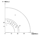
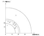
- FIG. 5 is a diagram showing an example of the determination content of the load level in the in-vehicle device according to the first embodiment of the present disclosure.
- the horizontal axis shows the operating time in the state information
- the vertical axis shows the amount of data in the state information.
- FIG. 5 shows the load level when the speed of the vehicle 1 is 40 km / h.
- the load level is determined to be 1.
- the load level is determined to be 2.
- the load level is determined to be 3.
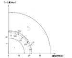
- FIG. 6 is a diagram showing another example of the determination content of the load level in the in-vehicle device according to the first embodiment of the present disclosure.
- the horizontal axis shows the number of operations or the operation time in the state information
- the vertical axis shows the amount of data in the state information.
- FIG. 6 shows the load level when the speed of the vehicle 1 is 60 km / h.
- the load level is determined to be 1.
- the load level is determined to be 3.
- the load level is determined to be 4.
- the determination content of the load level differs depending on the speed of the vehicle 1. More specifically, the higher the speed of the vehicle 1, the finer the load level is classified.
- the determination model is not limited to a configuration in which the load level is determined based on the operating time and the amount of data in the state information, and may be a configuration in which the load level is determined based on the number of operating hours and the amount of data.
- the allocation unit 23 predicts the processing load related to the target processing of its own in-vehicle device 101 based on the state information.
- the allocation unit 23 acquires the determination model created by the processing unit 21 from the storage unit 24, uses the acquired determination model, and based on the state information received from the acquisition unit 22, the in-vehicle device 101. To determine the load level of.
- the allocation unit 23 inputs the state information received from the acquisition unit 22 into the determination model.
- the judgment model When the state information is input, the judgment model outputs, for example, the load level information which is the state information with the load level corresponding to the state information as the judgment result as the prediction result.
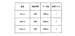
- FIG. 7 is a diagram showing an example of load level information used in the in-vehicle device according to the first embodiment of the present disclosure.
- the load level is "1" when the speed of the vehicle 1 is "0 km / h", the operating time is “15 seconds”, and the amount of data is “10 Mbps”.
- the speed of the vehicle 1 is "40 km / h”
- the operating time is "25 seconds”
- the amount of data is "20 Mbps”
- the load level is "2”.
- the speed of the vehicle 1 is "60 km / h”
- the operating time is "35 seconds”
- the amount of data is "30 Mbps”
- the load level is "3".
- the allocation unit 23 determines the number of available physical resources according to the state indicated by the state information acquired by the acquisition unit 22. Then, the allocation unit 23 changes the allocation of physical resources used for the target process, which is one or a plurality of types of processes to be performed by the in-vehicle device 101.
- the allocation unit 23 changes the allocation of the physical resources used for the target process according to the prediction result based on the state information acquired by the acquisition unit 22.
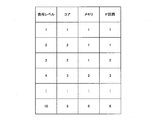
- the allocation unit 23 determines the number of physical resources allocated to the target process, for example, based on the allocation information stored in the storage unit 24.
- FIG. 8 is a diagram showing an example of allocation information used in the in-vehicle device according to the first embodiment of the present disclosure.
- the allocation information shows the correspondence between the load level and the physical resources allocated to the target process. For example, when the load level is 1, the number of cores 31 allocated is 1, the number of memories 32 is 1, and the number of IF circuits 33 is 1.
- the allocation unit 23 determines the number of physical resources corresponding to the prediction result, that is, the load level indicated by the load level information in the allocation information, as the number of physical resources allocated to the target process.
- the allocation unit 23 determines the number of cores 31 to be allocated to 2, the number of memories 32 to 1, and the number of IF circuits 33. Is determined to 2.
- the allocation unit 23 changes the number of physical resources allocated to the target process. .. That is, the allocation unit 23 allocates the determined number of physical resources to the target process.
- the allocation unit 23 changes a state in which a plurality of physical resources are allocated to a plurality of types of processes to a plurality of types of processes in which a number of physical resources smaller than the number of physical resources allocated to the plurality of types of processes is assigned. It is possible to switch to the assigned state.
- the allocation unit 23 reduces the number of cores 31 assigned to the target process to 2.
- the allocation unit 23 outputs an instruction to the OS 34 to reduce the number of cores 31 allocated to the target process from 3 to 2, for example.
- the OS 34 reduces the number of cores 31 assigned to the target process from 3 to 2 according to the instruction received from the allocation unit 23.
- the OS 34 for example, when software SW1 and software SW5 are assigned to core 31A, software SW2 and software SW3 are assigned to core 31B, and software SW4 is assigned to core 31C, software is assigned to core 31A.
- software SW1 and software SW5 are assigned to core 31A
- software SW2 and software SW3 are assigned to core 31B
- software SW4 is assigned to core 31C
- software is assigned to core 31A.
- the number of cores 31 assigned to the target process is reduced from 3 to 2.
- the allocation unit 23 stops at least one of power supply and clock supply to the physical resources that are not allocated to the target process.
- the allocation unit 23 is at least one of power supply and clock supply to the cores 31 that are not assigned. Stop one.
- the allocation unit 23 for example, in addition to the instruction to reduce the number of cores 31 allocated to the target process from 3 to 2, at least power supply and clock supply to the cores 31 that are not allocated.
- a stop instruction to stop one of them is output to the OS 34.
- the OS 34 performs a process of stopping at least one of the power supply and the clock supply to the core 31 which is out of the allocation according to the stop instruction received from the allocation unit 23.
- the OS 34 sets, for example, the value of a register or the like in the processing unit 21 so as to stop at least one of the power supply and the clock supply to the core 31.
- the processing unit 21 switches at least one of the switch 37 connected between the core 31 and the clock generation circuit 35 and the switch 37 connected between the core 31 and the power supply 36. By turning it off, at least one of the power supply and the clock supply to the core 31 is stopped.
- the allocation unit 23 may be configured to execute the allocation change when the state in which the physical resource allocation should be changed continues for a predetermined time.
- FIG. 9 is a diagram showing an example of physical resource allocation according to the load level by the in-vehicle device according to the first embodiment of the present disclosure.
- the allocation unit 23 determines the load level indicated by the prediction result, that is, the load level information, as the load level 3 based on the state information L1 at a certain timing.
- the allocation unit 23 determines to maintain the number of physical resources allocated to the target process to the number of physical resources corresponding to the load level 3.
- the allocation unit 23 determines the load level as the load level 2 based on the state information L2 at the next timing.
- the allocation unit 23 corresponds the number of physical resources allocated to the target process to the prediction result, that is, the load level 2 indicated by the load level information. Decide to maintain the number of physical resources corresponding to load level 3 rather than the number of physical resources.
- the allocation unit 23 determines the load level as the load level 2 based on the state information L3 at the next timing.
- the allocation unit 23 corresponds the number of physical resources allocated to the target process to the prediction result, that is, the load level 2 indicated by the load level information. Decide to maintain the number of physical resources corresponding to load level 3 rather than the number of physical resources.
- the allocation unit 23 determines the load level as the load level 2 based on the state information L4 at the next timing.
- the allocation unit 23 determines the number of physical resources allocated to the target process for the physical resources corresponding to the load level 2. Decide on a number.
- the allocation unit 23 refers to the allocation information shown in FIG. 8, for example, and since the determined number of physical resources is different from the current number of physical resources allocated to the target process, the physical resource allocated to the target process. Change the number of.
- the allocation unit 23 in the in-vehicle device 101 may be configured to provide hysteresis when reducing the number of physical resources allocated to the target process.
- the allocation unit 23 executes the allocation change when the state in which the physical resource allocation should be changed continues for a predetermined time.
- FIG. 10 is a diagram showing an example of the determination content of the load level provided with hysteresis in the in-vehicle device according to the first embodiment of the present disclosure.
- the allocation unit 23 determines the load level indicated by the prediction result, that is, the load level information, as the load level 3 based on the state information L5 at a certain timing.
- the allocation unit 23 determines to maintain the number of physical resources allocated to the target process to the number of physical resources corresponding to the load level 3.
- the allocation unit 23 determines the load level as the load level 2 based on the state information L6 at the next timing. At this time, the allocation unit 23 determines that the state information L6 is in a state exceeding the hysteresis HL.
- the allocation unit 23 determines the number of physical resources allocated to the target process, not the number of physical resources corresponding to the load level 2 indicated by the prediction result, that is, the load level information, but the number of physical resources corresponding to the load level 3. Decide to keep in.
- the allocation unit 23 determines the load level as the load level 2 based on the state information L7 at the next timing. At this time, the allocation unit 23 determines that the state information L7 is below the hysteresis HL.
- the allocation unit 23 determines the number of physical resources allocated to the target process, that is, the physical corresponding to the load level 2 indicated by the prediction result, that is, the load level information. Decide to maintain the number of physical resources corresponding to load level 3 rather than the number of resources.
- the allocation unit 23 determines the load level as the load level 2 based on the state information L8 at the next timing, and further determines the load level as the load level 2 based on the state information L9 at the next timing. .. At this time, the allocation unit 23 determines that the state information L8 and the state information L9 are in a state below the hysteresis HL.
- the allocation unit 23 determines the number of physical resources allocated to the target process of the physical resources corresponding to the load level 2. Decide on a number.
- the allocation unit 23 refers to the allocation information shown in FIG. 8, for example, and since the determined number of physical resources is different from the current number of physical resources allocated to the target process, the physical resource allocated to the target process. Change the number of.
- FIG. 11 is a diagram showing an example of the determination content of the load level provided with a plurality of hysteresiss in the in-vehicle device according to the first embodiment of the present disclosure.
- a hysteresis HLU and a hysteresis HLD are provided.
- the allocation unit 23 determines the load level indicated by the prediction result, that is, the load level information, as the load level 3 based on the state information L10 at a certain timing. Here, the allocation unit 23 determines to maintain the number of physical resources allocated to the target process to the number of physical resources corresponding to the load level 3.
- the allocation unit 23 determines the load level 2 based on the state information L11 at the next timing. At this time, the allocation unit 23 determines that the state information L11 is below the hysteresis HLU and exceeds the hysteresis HLD.
- the allocation unit 23 determines the number of physical resources allocated to the target process, not the number of physical resources corresponding to the load level 2 indicated by the prediction result, that is, the load level information, but the number of physical resources corresponding to the load level 3. Decide to keep in.
- the allocation unit 23 determines the load level as the load level 2 based on the state information L12 at the next timing. At this time, the allocation unit 23 determines that the state information L12 is below the hysteresis HLD.
- the allocation unit 23 determines the number of physical resources allocated to the target process to the number of physical resources corresponding to the determined load level 2.
- the allocation unit 23 refers to the allocation information shown in FIG. 8, for example, and since the determined number of physical resources is different from the current number of physical resources allocated to the target process, the physical resource allocated to the target process. Change the number of.
- the allocation unit 23 can switch from a state in which a plurality of physical resources are allocated to a plurality of types of processes to a state in which a larger number of physical resources are allocated to the plurality of types of processes.
- the allocation unit 23 increases the number of cores 31 assigned to the target process to 3.
- the allocation unit 23 outputs an instruction to the OS 34 to increase the number of cores 31 allocated to the target process from 2 to 3, for example.
- the OS 34 increases the number of cores 31 assigned to the target process from 2 to 3 according to the instruction received from the allocation unit 23.
- the allocation unit 23 starts at least one of power supply and clock supply to the physical resource to which the target process is newly allocated.
- the allocation unit 23 supplies at least one of the power supply and the clock supply to the newly allocated cores 31. Start one.
- the allocation unit 23 for example, in addition to the instruction to increase the number of cores 31 allocated to the target process from 2 to 3, supplies power and clocks to the newly allocated cores 31.
- a start instruction to start at least one of them is output to the OS 34.
- the OS 34 performs a process of starting at least one of power supply and clock supply to the newly assigned core 31 according to the start instruction received from the allocation unit 23.
- the OS 34 sets, for example, the values of registers and the like in the processing unit 21 so as to supply power and clock to the core 31.
- the processing unit 21 turns on the switch 37 connected between the core 31 and the clock generation circuit 35, and the switch 37 connected between the core 31 and the power supply 36. Power supply and clock supply to the core 31 are performed.
- the allocation unit 23 may be configured to execute the allocation change when the state in which the physical resource allocation should be changed continues for a predetermined time.
- FIG. 12 is a diagram showing another example of how the vehicle-mounted device according to the first embodiment of the present disclosure determines the allocation of physical resources according to the load level.
- the allocation unit 23 determines the load level indicated by the prediction result, that is, the load level information, as the load level 2 based on the state information L13 at a certain timing. Here, the allocation unit 23 determines to maintain the number of physical resources allocated to the target process to the number of physical resources corresponding to the load level 2.
- the allocation unit 23 determines the load level as the load level 3 based on the state information L14 at the next timing.
- the allocation unit 23 corresponds to the number of physical resources allocated to the target process according to the prediction result, that is, the load level 3 indicated by the load level information. Decide to maintain the number of physical resources corresponding to load level 2 rather than the number of physical resources.
- the allocation unit 23 determines the load level as the load level 3 based on the state information L15 at the next timing.
- the allocation unit 23 determines the number of physical resources allocated to the target process for the physical resources corresponding to the load level 2. Decide on a number.
- the allocation unit 23 refers to the allocation information shown in FIG. 8, for example, and since the determined number of physical resources is different from the current number of physical resources allocated to the target process, the physical resource allocated to the target process. Change the number of. [Example 5 of changing physical resource allocation]
- the allocation unit 23 in the in-vehicle device 101 may be configured to provide hysteresis when increasing the number of physical resources allocated to the target process.
- the allocation unit 23 executes the allocation change when the state in which the physical resource allocation should be changed continues for a predetermined time, as in the change example 4.
- FIG. 13 is a diagram showing another example of the determination content of the load level provided with hysteresis in the in-vehicle device according to the first embodiment of the present disclosure.
- the allocation unit 23 determines the load level indicated by the prediction result, that is, the load level information, as the load level 2 based on the state information L16 at a certain timing. At this time, the allocation unit 23 determines that the state information L16 is below the hysteresis HL.
- the allocation unit 23 determines the load level as the load level 2 based on the state information L17 at the next timing, and further determines the load level as the load level 2 based on the state information L18 at the next timing. .. At this time, the allocation unit 23 determines that the state information L17 and the state information L18 are in a state exceeding the hysteresis HL.
- the allocation unit 23 corresponds to the number of physical resources allocated to the target process according to the prediction result, that is, the load level 2 indicated by the load level information. It is determined not by the number of physical resources but by the number of physical resources corresponding to the load level 3.
- the allocation unit 23 refers to the allocation information shown in FIG. 8, for example, and since the determined number of physical resources is different from the current number of physical resources allocated to the target process, the physical resource allocated to the target process. Change the number of.
- FIG. 14 is a diagram showing an example of the determination content of the load level provided with a plurality of hysteresiss in the in-vehicle device according to the first embodiment of the present disclosure.
- a hysteresis HLU and a hysteresis HLD are provided.
- the allocation unit 23 determines the load level indicated by the prediction result, that is, the load level information, as the load level 2 based on the state information L19 at a certain timing. At this time, the allocation unit 23 determines that the state information L19 is below the hysteresis HLD.
- the allocation unit 23 determines the load level 2 based on the state information L20 at the next timing. At this time, the allocation unit 23 determines that the state information L20 is below the hysteresis HLU and exceeds the hysteresis HLD.
- the allocation unit 23 determines the load level as the load level 2 based on the state information L21 at the next timing. At this time, the allocation unit 23 determines that the state information L21 is in a state exceeding the hysteresis HLU.
- the allocation unit 23 determines the number of physical resources allocated to the target process, not the number of physical resources corresponding to the load level 2 indicated by the prediction result, that is, the load level information, but the number of physical resources corresponding to the load level 3. To decide.
- the allocation unit 23 refers to the allocation information shown in FIG. 8, for example, and since the determined number of physical resources is different from the current number of physical resources allocated to the target process, the physical resource allocated to the target process. Change the number of.
- the allocation of physical resources may be changed based on the degree of consumption of physical resources.
- the acquisition unit 22 further acquires a plurality of consumption information regarding the degree of consumption of each of the plurality of physical resources.
- the acquisition unit 22 monitors the operating time of each of the core 31, the memory 32, and the IF circuit 33. Specifically, the acquisition unit 22 creates, for example, consumption information indicating the operating time for each physical resource at predetermined time intervals and stores it in the storage unit 24.
- the consumption information may be information based on the operating time. More specifically, the consumption information includes, for example, the operating time acquired by the acquisition unit 22 and the power consumption and life of the physical resource corresponding to the operating time when the power consumption and life are different for each physical resource. The degree of consumption calculated based on this may be indicated.
- FIG. 15 is a diagram showing an example of consumption information used in the in-vehicle device according to the first embodiment of the present disclosure.
- the operating time of the core 31A is 100 hours
- the operating time of the core 31B is 200 hours
- the operating time of the core 31C is 50 hours
- the operating time of the memory 32A is 100 hours.
- the operating time of the IF circuit 33A is 100 hours.
- the allocation unit 23 changes the physical resource allocation based on the consumption information acquired by the acquisition unit 22.
- the allocation unit 23 outputs to the OS 34 an instruction to reduce the number of cores 31 assigned to the target process, including information indicating the core 31 to be unassigned to the target process.
- the allocation unit 23 refers to the consumption information in the storage unit 24 and allocates the cores 31 in order from the core 31 having the longest operating time included in the consumption information. remove.
- the allocation unit 23 instructs the core 31B, which is the core 31 having the longest operating time included in the consumption information shown in FIG. Include in.
- the allocation unit 23 outputs to the OS 34, for example, in the instruction to increase the number of cores 31 assigned to the target process, including information indicating the core 31 to which the target process is newly allocated.
- the allocation unit 23 allocates the cores 31 included in the consumption information in order from the shortest operating time by referring to the consumption information in the storage unit 24.
- the allocation unit 23 instructs the core 31C, which is the core 31 having the shortest operating time included in the consumption information shown in FIG. Include in.
- Each device in the in-vehicle communication system includes a computer including a memory, and an arithmetic processing unit such as a CPU in the computer is a program including a part or all of each step of the following sequence or flowchart. Are read from the memory and executed.
- the programs of these plurality of devices can be installed from the outside.
- the programs of these plurality of devices are distributed in a state of being stored in a recording medium.
- FIG. 16 is a flowchart defining an operation procedure when the in-vehicle device according to the first embodiment of the present disclosure manages its own physical resources.
- the in-vehicle device 101 acquires state information indicating the state of the vehicle 1 (step S101).
- the in-vehicle device 101 determines its own load level based on the acquired state information. That is, the in-vehicle device 101 predicts its own processing load (step S102).
- the in-vehicle device 101 changes the allocation of the physical resources used for the target processing according to the prediction result, that is, the determined load level. More specifically, the in-vehicle device 101 changes the physical resource allocation when the determined load level is different from its own current load level (YES in step S103).
- the in-vehicle device 101 may provide hysteresis in a state in which the allocation should be changed, or may change the allocation when the state in which the allocation should be changed continues for a predetermined time (step S104).
- the in-vehicle device 101 switches to a state in which a larger number of physical resources are allocated to the target process. At this time, the in-vehicle device 101 is assigned in order from the core 31 having the shortest operating time included in the consumption information (step S105). Then, the in-vehicle device 101 acquires the state information at the next timing (step S101).
- the in-vehicle device 101 switches to a state in which a smaller number of physical resources are allocated to the target process.
- the in-vehicle device 101 is, for example, unassigned in order from the core 31 having the longest operating time included in the consumption information (step S106). Then, the in-vehicle device 101 acquires the state information at the next timing (step S101).
- the in-vehicle device 101 acquires the state information at the next timing without changing the physical resource allocation. (Step S101).
- the allocation unit 23 is configured to predict the processing load related to the target processing of its own in-vehicle device 101 based on the state information. It is not limited to this.
- the allocation unit 23 may be configured not to predict the processing load. More specifically, the allocation unit 23 may be configured to change the allocation of physical resources based on the state information without determining the load level, for example.
- the allocation unit 23 is configured to determine the number of available physical resources according to the state indicated by the state information. It is not limited to.
- the allocation unit 23 may be configured so as not to determine the number of available physical resources.
- the allocation unit 23 outputs, for example, an instruction to increase or decrease the physical resources allocated to the target process to the OS 34 without determining the number of physical resources.
- the in-vehicle device 101 is configured to stop at least one of power supply and clock supply to physical resources that are not assigned to the target process. It is not limited. The in-vehicle device 101 may be configured so as not to stop the power supply and the clock supply to the physical resource.
- the in-vehicle device 101 is defined as a central gateway as an example, but the present invention is not limited to this.
- the in-vehicle device 101 may be, for example, an electronic control unit different from the central gateway.
- the power consumption of the in-vehicle device increases as the number of applications that the in-vehicle device should provide increases. Such an increase in power consumption has a large effect on, for example, the cruising range of an electric vehicle.
- the acquisition unit 22 acquires the state information indicating the state of the vehicle 1.
- the allocating unit 23 changes the allocation of physical resources used for the target processing, which is one or a plurality of types of processing to be performed by its own in-vehicle device 101, according to the state indicated by the state information acquired by the acquiring unit 22.
- the allocation of the physical resources to be executed for the target processing is changed for the plurality of physical resources in the in-vehicle device 101 according to the state of the vehicle 1. It is possible to select an appropriate physical resource and perform the target processing.
- the allocation unit 23 predicts the processing load of its own in-vehicle device 101 based on the state information, and allocates physical resources according to the prediction result. change.
- the allocation unit 23 determines the number of available physical resources according to the state indicated by the state information, and targets the determined number of physical resources. Assign to processing.
- the number of usable physical resources can be increased or decreased according to the state of the vehicle 1, so that the power consumption can be reduced more effectively.
- the allocation unit 23 sets a state in which a plurality of physical resources are allocated to a plurality of types of processing to be performed by the vehicle-mounted device 101. It is possible to switch to a state in which a number of physical resources less than the number of physical resources allocated to the processing of the above is allocated to the plurality of types of processing.
- the allocation unit 23 when the number of physical resources allocated to the target process is reduced, the allocation unit 23 supplies power and clocks to the physical resources that are not allocated to the target process. Stop at least one of the above.
- the allocation unit 23 provides hysteresis depending on whether the number of physical resources allocated to the target process is decreased or increased, or the physical resources are allocated. Executes the assignment change when the state in which the assignment should be changed continues for a predetermined time.
- the acquisition unit 22 acquires a plurality of consumption information regarding the degree of consumption of each of the plurality of physical resources.
- the allocation unit 23 changes the physical resource allocation based on each consumption information acquired by the acquisition unit 22.
- the state information indicating the state of the vehicle 1 is acquired.
- the allocation of physical resources used for the target process which is one or a plurality of types of processes to be performed by the in-vehicle device 101, is changed according to the state indicated by the acquired state information.
- the allocation of the physical resources to be executed for the target processing is changed for the plurality of physical resources in the in-vehicle device 101 according to the state of the vehicle 1. It is possible to select an appropriate physical resource and perform the target processing.
- the present embodiment relates to an in-vehicle device in which the processing load of the in-vehicle device is predicted outside the in-vehicle device as compared with the in-vehicle device according to the first embodiment. Except for the contents described below, the device is the same as the in-vehicle device according to the first embodiment.
- FIG. 17 is a diagram showing a configuration of a vehicle management system according to a second embodiment of the present disclosure.
- the vehicle management system 401 includes an in-vehicle communication system 302 and a management device 201.
- the in-vehicle communication system 302 includes an in-vehicle device 102 instead of the in-vehicle device 101 as compared with the in-vehicle communication system 301 shown in FIG.
- the in-vehicle device 102 and the management device 201 are, for example, servers.
- the configuration of the functional block of the in-vehicle device 102 is the same as that of the in-vehicle device 101 shown in FIG.
- the in-vehicle device 102 further performs wireless communication processing with the wireless base station device 161 according to a communication standard such as LTE (Long Term Evolution) or 4G or 5G, as compared with the in-vehicle device 101 shown in FIG.
- Software SW6 (not shown) having the function of TCU (Telematics Communication Unit) is installed.
- the software SW6 functions as the communication unit 25 shown in FIG.
- the in-vehicle device 102 can communicate with the management device 201 outside the vehicle 1 via the wireless base station device 161 by using the software SW6.
- the communication unit 25 in the in-vehicle device 102 transmits the state information indicating the state of the vehicle 1 to the management device 201.
- the acquisition unit 22 in the in-vehicle device 102 creates, for example, the above-mentioned state information and outputs it to the processing unit 21.
- the processing unit 21 transmits the state information received from the acquisition unit 22 to the management device 201 via the communication unit 25 and the wireless base station device 161 by wireless communication.
- the management device 201 receives the state information transmitted from the in-vehicle device 102, and stores the received state information in a storage unit (not shown).
- the management device 201 predicts the processing load of the vehicle-mounted device 102 based on the state information received from the vehicle-mounted device 102.
- the management device 201 creates a determination model which is an example of a machine learning model, similarly to the processing unit 21 in the in-vehicle device 101.
- the management device 201 determines the load level of the vehicle-mounted device 102 based on the state information received from the vehicle-mounted device 102 by using the created determination model, similarly to the allocation unit 23 in the vehicle-mounted device 101.
- the management device 201 transmits, for example, load level information to the in-vehicle device 102 as load information indicating the prediction result.
- the communication unit 25 in the in-vehicle device 102 receives the load level information transmitted from the management device 201 via the wireless base station device 161 and outputs the received load level information to the processing unit 21.
- the processing unit 21 outputs the load level information received from the communication unit 25 to the allocation unit 23.
- the allocation unit 23 determines the number of physical resources allocated to the target process based on the load level information received from the processing unit 21 and the allocation information in the storage unit 24, and changes the allocation of the physical resources used for the target process. To do.
- FIG. 18 is a diagram showing a sequence for managing physical resources in an in-vehicle device in the vehicle management system according to the second embodiment of the present disclosure.
- the in-vehicle device 102 acquires the state information indicating the state of the vehicle 1 (step S201).
- the in-vehicle device 102 transmits the acquired state information to the management device 201 (step S202).
- the management device 201 receives the state information transmitted from the vehicle-mounted device 102, and predicts the processing load of the vehicle-mounted device 102 based on the received state information. That is, the management device 201 determines the load level of the in-vehicle device 102 based on the received state information (step S203).
- the management device 201 transmits, for example, load level information to the in-vehicle device 102 as load information indicating the prediction result (step S204).
- the in-vehicle device 102 changes the allocation of the physical resources used for the target processing according to the prediction result indicated by the load information. More specifically, the in-vehicle device 102 receives the load level information transmitted from the management device 201, determines the number of physical resources allocated to the target process based on the received load level information, and uses the load level information for the target process. The allocation of physical resources to be obtained is changed (step S205).
- the in-vehicle device 102 and the management device 201 repeat the same operations as in steps S201 to S205.
- the in-vehicle device 102 includes a plurality of physical resources.
- the in-vehicle device 102 transmits the state information indicating the state of the vehicle 1 to the management device 201.
- the management device 201 predicts the processing load of the vehicle-mounted device 102 based on the state information received from the vehicle-mounted device 102, and transmits the load information indicating the prediction result to the vehicle-mounted device 102.
- the in-vehicle device 102 changes the allocation of physical resources used for the target process, which is one or a plurality of types of processes to be performed by the in-vehicle device 102, according to the prediction result indicated by the load information received from the management device 201.
- the allocation of the physical resources to be executed for the target processing is changed for the plurality of physical resources in the in-vehicle device 101 according to the state of the vehicle 1. It is possible to select an appropriate physical resource and perform the target processing.
- the in-vehicle device 102 transmits the state information indicating the state of the vehicle to the management device 201.
- the management device 201 predicts the processing load of the vehicle-mounted device based on the state information received from the vehicle-mounted device 102, and transmits the load information indicating the prediction result to the vehicle-mounted device 102.
- the vehicle-mounted device 102 changes the allocation of physical resources used for the target processing, which is one or a plurality of types of processing to be performed by the vehicle-mounted device 102, according to the prediction result indicated by the load information received from the management device 201. ..
- the allocation of the physical resources to be executed for the target processing is changed for the plurality of physical resources in the in-vehicle device 101 according to the state of the vehicle 1. It is possible to select an appropriate physical resource and perform the target processing.
- the allocation unit is an in-vehicle device that predicts the processing load of the in-vehicle device related to the target processing based on the state information.
- In-vehicle devices that include multiple physical resources and Equipped with a management device
- the in-vehicle device transmits state information indicating the state of the vehicle to the management device.
- the management device predicts the processing load of the vehicle-mounted device based on the state information received from the vehicle-mounted device, and transmits load information indicating the prediction result to the vehicle-mounted device.
- the in-vehicle device changes the allocation of the physical resource used for the target process, which is one or a plurality of types of processes to be performed by the in-vehicle device, according to the prediction result indicated by the load information received from the management device.
- the vehicle-mounted device is a vehicle management system that predicts the processing load of the vehicle-mounted device related to the target processing based on the state information.
- Vehicle 10 CAN Bus 11 Ethernet Cable 21 Processing Unit 22 Acquisition Unit 23 Allocation Unit 24 Storage Unit 25 Communication Unit 31, 31A, 31B, 31C, 31D Core 32, 32A, 32B Memory 33, 33A, 33B IF Circuit 34 OS 35 Clock generation circuit 36 Power supply 37 Switch 101,102 In-vehicle device 161 Wireless base station equipment 201 Management device 301 In-vehicle communication system 401 Vehicle management system
Landscapes
- Engineering & Computer Science (AREA)
- Software Systems (AREA)
- Theoretical Computer Science (AREA)
- General Engineering & Computer Science (AREA)
- Physics & Mathematics (AREA)
- General Physics & Mathematics (AREA)
- Computer Networks & Wireless Communication (AREA)
- Signal Processing (AREA)
- Health & Medical Sciences (AREA)
- Computing Systems (AREA)
- General Health & Medical Sciences (AREA)
- Medical Informatics (AREA)
- Chemical & Material Sciences (AREA)
- Combustion & Propulsion (AREA)
- Mechanical Engineering (AREA)
- Combined Controls Of Internal Combustion Engines (AREA)
- Traffic Control Systems (AREA)
- Management, Administration, Business Operations System, And Electronic Commerce (AREA)
Priority Applications (3)
| Application Number | Priority Date | Filing Date | Title |
|---|---|---|---|
| JP2021532750A JP7405142B2 (ja) | 2019-07-17 | 2020-06-25 | 車載装置、車両管理システム、リソース管理方法およびリソース管理プログラム |
| CN202080041137.5A CN113994646A (zh) | 2019-07-17 | 2020-06-25 | 车载装置、车辆管理系统、资源管理方法以及资源管理程序 |
| US17/627,925 US12367075B2 (en) | 2019-07-17 | 2020-06-25 | In-vehicle device, vehicle management system, resource management method, and resource management program for allocation of computing recourses based on a usage state |
Applications Claiming Priority (2)
| Application Number | Priority Date | Filing Date | Title |
|---|---|---|---|
| JP2019131582 | 2019-07-17 | ||
| JP2019-131582 | 2019-07-17 |
Publications (1)
| Publication Number | Publication Date |
|---|---|
| WO2021010124A1 true WO2021010124A1 (ja) | 2021-01-21 |
Family
ID=74209820
Family Applications (1)
| Application Number | Title | Priority Date | Filing Date |
|---|---|---|---|
| PCT/JP2020/024982 Ceased WO2021010124A1 (ja) | 2019-07-17 | 2020-06-25 | 車載装置、車両管理システム、リソース管理方法およびリソース管理プログラム |
Country Status (4)
| Country | Link |
|---|---|
| US (1) | US12367075B2 (https=) |
| JP (1) | JP7405142B2 (https=) |
| CN (1) | CN113994646A (https=) |
| WO (1) | WO2021010124A1 (https=) |
Cited By (1)
| Publication number | Priority date | Publication date | Assignee | Title |
|---|---|---|---|---|
| WO2024224930A1 (ja) * | 2023-04-25 | 2024-10-31 | 住友電気工業株式会社 | 車載装置、および運転支援装置 |
Citations (3)
| Publication number | Priority date | Publication date | Assignee | Title |
|---|---|---|---|---|
| JP2010079908A (ja) * | 2008-09-26 | 2010-04-08 | Samsung Electronics Co Ltd | メモリ管理装置及びその方法 |
| JP2016177423A (ja) * | 2015-03-19 | 2016-10-06 | 三菱電機株式会社 | マルチコア・マイクロコントローラを備えた制御システムおよびその制御方法 |
| JP2017506773A (ja) * | 2013-12-18 | 2017-03-09 | クアルコム,インコーポレイテッド | 動作寿命を延ばし、性能を最大化するためのマルチコアシステム設計のランタイム最適化 |
Family Cites Families (18)
| Publication number | Priority date | Publication date | Assignee | Title |
|---|---|---|---|---|
| JP2001202155A (ja) | 2000-01-18 | 2001-07-27 | Hitachi Ltd | 低消費電力処理装置 |
| US6934864B2 (en) * | 2002-01-11 | 2005-08-23 | International Business Machines Corporation | System and method for co-operative thermal management of electronic devices within a common housing |
| US20050060590A1 (en) * | 2003-09-16 | 2005-03-17 | International Business Machines Corporation | Power-aware workload balancing usig virtual machines |
| JP5092363B2 (ja) * | 2006-11-21 | 2012-12-05 | 日産自動車株式会社 | 車両の発進制御装置 |
| JP2009211397A (ja) * | 2008-03-04 | 2009-09-17 | Toyota Infotechnology Center Co Ltd | 無線通信方法及び車両通信システム |
| US8041976B2 (en) * | 2008-10-01 | 2011-10-18 | International Business Machines Corporation | Power management for clusters of computers |
| JP2010146184A (ja) * | 2008-12-17 | 2010-07-01 | Toyota Motor Corp | 車載計算装置 |
| CN101519073A (zh) * | 2009-04-07 | 2009-09-02 | 北京大学 | 一种混合动力汽车行驶负载预测方法 |
| WO2012063334A1 (ja) | 2010-11-10 | 2012-05-18 | 株式会社日立製作所 | 仮想マシンのライブマイグレーションを支援するためのメモリ制御装置及びi/oスイッチ |
| US8695008B2 (en) | 2011-04-05 | 2014-04-08 | Qualcomm Incorporated | Method and system for dynamically controlling power to multiple cores in a multicore processor of a portable computing device |
| JP5758358B2 (ja) | 2012-08-09 | 2015-08-05 | 日本電信電話株式会社 | 仮想マシンシステム及びその高速ライブマイグレーション方法 |
| KR101659705B1 (ko) | 2013-02-05 | 2016-09-26 | 퀄컴 인코포레이티드 | 보장된 과도 데드라인들로 중앙 프로세싱 유닛 전력을 제어하기 위한 시스템 및 방법 |
| JP5876425B2 (ja) | 2013-02-12 | 2016-03-02 | 日本電信電話株式会社 | 仮想マシンのライブマイグレーションスケジューリング方法及び仮想マシンシステム |
| US20150169363A1 (en) | 2013-12-18 | 2015-06-18 | Qualcomm Incorporated | Runtime Optimization of Multi-core System Designs for Increased Operating Life and Maximized Performance |
| JP6247648B2 (ja) | 2015-01-22 | 2017-12-13 | 日本電信電話株式会社 | ライブマイグレーション実行装置およびその動作方法 |
| DE112015007188T5 (de) | 2015-12-18 | 2018-09-13 | Intel Corporation | Batch-Migration virtueller Maschinen während des aktiven Bertriebs |
| US11742038B2 (en) * | 2017-08-11 | 2023-08-29 | Advanced Micro Devices, Inc. | Method and apparatus for providing wear leveling |
| JP7294771B2 (ja) * | 2018-04-02 | 2023-06-20 | トヨタ自動車株式会社 | 車載装置および車載装置のクロック設定方法およびプログラム |
-
2020
- 2020-06-25 US US17/627,925 patent/US12367075B2/en active Active
- 2020-06-25 WO PCT/JP2020/024982 patent/WO2021010124A1/ja not_active Ceased
- 2020-06-25 JP JP2021532750A patent/JP7405142B2/ja active Active
- 2020-06-25 CN CN202080041137.5A patent/CN113994646A/zh active Pending
Patent Citations (3)
| Publication number | Priority date | Publication date | Assignee | Title |
|---|---|---|---|---|
| JP2010079908A (ja) * | 2008-09-26 | 2010-04-08 | Samsung Electronics Co Ltd | メモリ管理装置及びその方法 |
| JP2017506773A (ja) * | 2013-12-18 | 2017-03-09 | クアルコム,インコーポレイテッド | 動作寿命を延ばし、性能を最大化するためのマルチコアシステム設計のランタイム最適化 |
| JP2016177423A (ja) * | 2015-03-19 | 2016-10-06 | 三菱電機株式会社 | マルチコア・マイクロコントローラを備えた制御システムおよびその制御方法 |
Cited By (1)
| Publication number | Priority date | Publication date | Assignee | Title |
|---|---|---|---|---|
| WO2024224930A1 (ja) * | 2023-04-25 | 2024-10-31 | 住友電気工業株式会社 | 車載装置、および運転支援装置 |
Also Published As
| Publication number | Publication date |
|---|---|
| JP7405142B2 (ja) | 2023-12-26 |
| CN113994646A (zh) | 2022-01-28 |
| JPWO2021010124A1 (https=) | 2021-01-21 |
| US12367075B2 (en) | 2025-07-22 |
| US20220261285A1 (en) | 2022-08-18 |
Similar Documents
| Publication | Publication Date | Title |
|---|---|---|
| CN112000458B (zh) | 汽车计算任务配置给有异构能力的联网设备的方法和装置 | |
| EP4052127A1 (en) | A system and method for scheduling computing tasks on a network of autonomous vehicles | |
| JP2021124902A (ja) | 車両制御装置、車両制御方法、及び車両制御プログラム | |
| JP7447782B2 (ja) | 車載コンピュータ、コンピュータ実行方法及びコンピュータプログラム | |
| CN117349004A (zh) | 用于云协调的车辆数据收集的系统和方法 | |
| WO2018127394A1 (en) | Scalable control system for a motor vehicle | |
| CN118585318A (zh) | 车端计算资源的分配方法及车辆 | |
| JP7405142B2 (ja) | 車載装置、車両管理システム、リソース管理方法およびリソース管理プログラム | |
| US11093291B2 (en) | Resource assignment using CDA protocol in distributed processing environment based on task bid and resource cost | |
| EP4567599A2 (en) | Bandwidth control method and system, electronic device, and vehicle | |
| JP2026036650A (ja) | リソーススケジューリング方法及び装置、並びにチップシステム、電子機器及び乗り物 | |
| CN116643892B (zh) | 内存管理方法、装置、芯片及交通设备 | |
| CN118964246A (zh) | 一种带宽控制方法、装置、集成电路、电子设备和载具 | |
| JP7439773B2 (ja) | 車載コンピュータ、コンピュータ実行方法及びコンピュータプログラム | |
| CN115243218B (zh) | 一种车辆网络资源分配方法、装置、设备及介质 | |
| CN100382034C (zh) | 信息处理设备和处理控制方法 | |
| JP7747202B2 (ja) | リソース割当方法および装置、ならびにコンピュータプログラム | |
| CN119348553B (zh) | 车辆控制方法、装置、控制器、存储介质及产品 | |
| JP7447781B2 (ja) | 車載コンピュータ、コンピュータ実行方法及びコンピュータプログラム | |
| EP4506826A2 (en) | Bandwidth control method and system, electronic device, vehicle, and storage medium | |
| WO2025197760A1 (ja) | 情報処理システム、プログラム | |
| CN121681074B (en) | Multi-core-based task scheduling method, device, equipment and medium | |
| CN119363686A (zh) | 一种算力扩展系统、资源分配方法、装置及存储介质 | |
| CN120832233A (zh) | 资源管理方法、装置、电子设备、存储介质及产品 | |
| CN117453387A (zh) | 车辆控制模块分配 |
Legal Events
| Date | Code | Title | Description |
|---|---|---|---|
| 121 | Ep: the epo has been informed by wipo that ep was designated in this application |
Ref document number: 20838879 Country of ref document: EP Kind code of ref document: A1 |
|
| ENP | Entry into the national phase |
Ref document number: 2021532750 Country of ref document: JP Kind code of ref document: A |
|
| NENP | Non-entry into the national phase |
Ref country code: DE |
|
| 122 | Ep: pct application non-entry in european phase |
Ref document number: 20838879 Country of ref document: EP Kind code of ref document: A1 |
|
| WWG | Wipo information: grant in national office |
Ref document number: 17627925 Country of ref document: US |