WO2021010124A1 - 車載装置、車両管理システム、リソース管理方法およびリソース管理プログラム - Google Patents
車載装置、車両管理システム、リソース管理方法およびリソース管理プログラム Download PDFInfo
- Publication number
- WO2021010124A1 WO2021010124A1 PCT/JP2020/024982 JP2020024982W WO2021010124A1 WO 2021010124 A1 WO2021010124 A1 WO 2021010124A1 JP 2020024982 W JP2020024982 W JP 2020024982W WO 2021010124 A1 WO2021010124 A1 WO 2021010124A1
- Authority
- WO
- WIPO (PCT)
- Prior art keywords
- vehicle
- physical resources
- allocation
- state
- vehicle device
- Prior art date
Links
Images


Classifications
-
- H—ELECTRICITY
- H04—ELECTRIC COMMUNICATION TECHNIQUE
- H04L—TRANSMISSION OF DIGITAL INFORMATION, e.g. TELEGRAPHIC COMMUNICATION
- H04L67/00—Network arrangements or protocols for supporting network services or applications
- H04L67/01—Protocols
- H04L67/10—Protocols in which an application is distributed across nodes in the network
- H04L67/104—Peer-to-peer [P2P] networks
- H04L67/1074—Peer-to-peer [P2P] networks for supporting data block transmission mechanisms
-
- G—PHYSICS
- G06—COMPUTING; CALCULATING OR COUNTING
- G06F—ELECTRIC DIGITAL DATA PROCESSING
- G06F9/00—Arrangements for program control, e.g. control units
- G06F9/06—Arrangements for program control, e.g. control units using stored programs, i.e. using an internal store of processing equipment to receive or retain programs
- G06F9/46—Multiprogramming arrangements
- G06F9/50—Allocation of resources, e.g. of the central processing unit [CPU]
- G06F9/5005—Allocation of resources, e.g. of the central processing unit [CPU] to service a request
- G06F9/5027—Allocation of resources, e.g. of the central processing unit [CPU] to service a request the resource being a machine, e.g. CPUs, Servers, Terminals
- G06F9/505—Allocation of resources, e.g. of the central processing unit [CPU] to service a request the resource being a machine, e.g. CPUs, Servers, Terminals considering the load
-
- F—MECHANICAL ENGINEERING; LIGHTING; HEATING; WEAPONS; BLASTING
- F02—COMBUSTION ENGINES; HOT-GAS OR COMBUSTION-PRODUCT ENGINE PLANTS
- F02D—CONTROLLING COMBUSTION ENGINES
- F02D45/00—Electrical control not provided for in groups F02D41/00 - F02D43/00
-
- H—ELECTRICITY
- H04—ELECTRIC COMMUNICATION TECHNIQUE
- H04L—TRANSMISSION OF DIGITAL INFORMATION, e.g. TELEGRAPHIC COMMUNICATION
- H04L67/00—Network arrangements or protocols for supporting network services or applications
- H04L67/01—Protocols
- H04L67/12—Protocols specially adapted for proprietary or special-purpose networking environments, e.g. medical networks, sensor networks, networks in vehicles or remote metering networks
-
- B—PERFORMING OPERATIONS; TRANSPORTING
- B60—VEHICLES IN GENERAL
- B60W—CONJOINT CONTROL OF VEHICLE SUB-UNITS OF DIFFERENT TYPE OR DIFFERENT FUNCTION; CONTROL SYSTEMS SPECIALLY ADAPTED FOR HYBRID VEHICLES; ROAD VEHICLE DRIVE CONTROL SYSTEMS FOR PURPOSES NOT RELATED TO THE CONTROL OF A PARTICULAR SUB-UNIT
- B60W50/00—Details of control systems for road vehicle drive control not related to the control of a particular sub-unit, e.g. process diagnostic or vehicle driver interfaces
- B60W50/06—Improving the dynamic response of the control system, e.g. improving the speed of regulation or avoiding hunting or overshoot
-
- G—PHYSICS
- G06—COMPUTING; CALCULATING OR COUNTING
- G06F—ELECTRIC DIGITAL DATA PROCESSING
- G06F2209/00—Indexing scheme relating to G06F9/00
- G06F2209/50—Indexing scheme relating to G06F9/50
- G06F2209/5019—Workload prediction
Definitions
- the present disclosure relates to in-vehicle devices, vehicle management systems, resource management methods and resource management programs.
- This application claims priority on the basis of Japanese Application Japanese Patent Application No. 2019-131582 filed on July 17, 2019, and incorporates all of its disclosures herein.
- Patent Document 1 discloses the following memory control device. That is, in the memory control device, a computer and an I / O device are connected, a specific area of the memory of the computer is divided into pages, and a diary bit array for storing the presence / absence of memory writing for each divided page. And, it has a memory write monitoring mechanism that monitors the memory write to the memory of the computer from the I / O device, and when the memory write from the I / O device to the specific area of the memory is observed by the monitoring mechanism. , The page on which the memory was written is determined from the address of the memory write, and it is recorded in the computer bit array that the memory was written to the page.
- Patent Document 2 discloses the following method. That is, in a portable computing device, it is a method for dynamically determining the degree of parallel processing of a processing load and automatically adjusting the number of cores that support the processing load, and is one or a plurality of multi-core processors. A step of monitoring the processing queue, a step of calculating the percentage of parallel processing based on the current operating mode of the multi-core processor and the monitoring of the one or more processing queues, and the calculation of parallel processing.
- the in-vehicle device of the present disclosure is an in-vehicle device mounted on a vehicle, and includes an acquisition unit that acquires state information indicating the state of the vehicle, a plurality of physical resources, and the state information acquired by the acquisition unit. It includes an allocation unit that changes the allocation of the physical resource used for the target process, which is one or a plurality of types of processes to be performed by the in-vehicle device according to the state shown.
- the vehicle management system of the present disclosure includes an in-vehicle device mounted on a vehicle and including a plurality of physical resources and a management device, and the in-vehicle device transmits state information indicating the state of the vehicle to the management device.
- the management device predicts the processing load of the vehicle-mounted device based on the state information received from the vehicle-mounted device, transmits load information indicating the prediction result to the vehicle-mounted device, and the vehicle-mounted device is the management device.
- the allocation of the physical resource used for the target process which is one or a plurality of types of processes to be performed by the vehicle-mounted device, is changed according to the prediction result indicated by the load information received from the vehicle.
- the resource management method of the present disclosure is a resource management method in an in-vehicle device mounted on a vehicle and having a plurality of physical resources, and shows a step of acquiring state information indicating the state of the vehicle and the acquired state information. It includes a step of changing the allocation of the physical resource used for the target process, which is one or a plurality of types of processes to be performed by the in-vehicle device according to the state.
- the resource management method of the present disclosure is a resource management method in a vehicle management system including an in-vehicle device mounted on a vehicle and including a plurality of physical resources and a management device, wherein the in-vehicle device is the above-mentioned.
- the management device Based on the step of transmitting the state information indicating the state of the vehicle to the management device and the state information received from the in-vehicle device, the management device predicts the processing load of the in-vehicle device and shows the prediction result.
- Target processing which is one or a plurality of types of processing to be performed by the vehicle-mounted device according to the step of transmitting information to the vehicle-mounted device and the prediction result indicated by the load information received from the management device. Includes a step of changing the allocation of said physical resources used in.
- the resource management program of the present disclosure is a resource management program used in an in-vehicle device mounted on a vehicle and having a plurality of physical resources, and the computer acquires state information indicating the state of the vehicle. Allocation to change the allocation of the physical resource used for the target process, which is one or a plurality of types of processes to be performed by the in-vehicle device, according to the acquisition unit and the state indicated by the state information acquired by the acquisition unit. It is a program to function as a department.
- the resource management program of the present disclosure is a resource management program used in the in-vehicle device of a vehicle management system including an in-vehicle device including a plurality of physical resources and a management device, which is an in-vehicle device mounted on a vehicle.
- the computer transmits the state information indicating the state of the vehicle to the management device, and shows the prediction result of the processing load of the vehicle-mounted device predicted based on the state information received from the vehicle-mounted device by the management device.
- It is a program for functioning as an allocation unit for changing the allocation of the physical resource used for a certain target process.
- One aspect of the present disclosure can be realized not only as an in-vehicle device provided with such a characteristic processing unit, but also as a semiconductor integrated circuit that realizes a part or all of the in-vehicle device.
- One aspect of the present disclosure can be realized not only as a vehicle management system provided with such a characteristic processing unit, but also as a program for causing a computer to execute such a characteristic processing step. Further, one aspect of the present disclosure can be realized as a semiconductor integrated circuit that realizes a part or all of a vehicle management system.
- FIG. 1 is a diagram showing a configuration of an in-vehicle communication system according to the first embodiment of the present disclosure.
- FIG. 2 is a functional block diagram of the vehicle-mounted device according to the first embodiment of the present disclosure.
- FIG. 3 is a diagram showing a configuration of hardware and software of an in-vehicle device according to the first embodiment of the present disclosure.
- FIG. 4 is a diagram showing an example of state information used in the in-vehicle device according to the first embodiment of the present disclosure.
- FIG. 5 is a diagram showing an example of the determination content of the load level in the in-vehicle device according to the first embodiment of the present disclosure.
- FIG. 1 is a diagram showing a configuration of an in-vehicle communication system according to the first embodiment of the present disclosure.
- FIG. 2 is a functional block diagram of the vehicle-mounted device according to the first embodiment of the present disclosure.
- FIG. 3 is a diagram showing a configuration of hardware and software of an in-vehicle device
- FIG. 6 is a diagram showing another example of the content of determining the load level in the in-vehicle device according to the first embodiment of the present disclosure.
- FIG. 7 is a diagram showing an example of load level information used in the vehicle-mounted device according to the first embodiment of the present disclosure.
- FIG. 8 is a diagram showing an example of allocation information used in the vehicle-mounted device according to the first embodiment of the present disclosure.
- FIG. 9 is a diagram showing an example of physical resource allocation according to the load level by the vehicle-mounted device according to the first embodiment of the present disclosure.
- FIG. 10 is a diagram showing an example of the determination content of the load level provided with hysteresis in the in-vehicle device according to the first embodiment of the present disclosure.
- FIG. 11 is a diagram showing an example of the determination content of the load level provided with a plurality of hysteresiss in the in-vehicle device according to the first embodiment of the present disclosure.
- FIG. 12 is a diagram showing another example of how the vehicle-mounted device according to the first embodiment of the present disclosure determines the allocation of physical resources according to the load level.
- FIG. 13 is a diagram showing another example of the determination content of the load level provided with hysteresis in the in-vehicle device according to the first embodiment of the present disclosure.
- FIG. 14 is a diagram showing an example of the determination content of the load level provided with a plurality of hysteresiss in the in-vehicle device according to the first embodiment of the present disclosure.
- FIG. 12 is a diagram showing another example of how the vehicle-mounted device according to the first embodiment of the present disclosure determines the allocation of physical resources according to the load level.
- FIG. 13 is a diagram showing another example of the determination content of the
- FIG. 15 is a diagram showing an example of consumption information used in the in-vehicle device according to the first embodiment of the present disclosure.
- FIG. 16 is a flowchart defining an operation procedure when the in-vehicle device according to the first embodiment of the present disclosure manages its own physical resources.
- FIG. 17 is a diagram showing a configuration of a vehicle management system according to a second embodiment of the present disclosure.
- FIG. 18 is a diagram showing a sequence for managing physical resources in an in-vehicle device in the vehicle management system according to the second embodiment of the present disclosure.
- ECUs Electronic Control Units
- the power consumption of the in-vehicle device increases as the number of applications that the in-vehicle device should provide increases. Such an increase in power consumption has a large effect on, for example, the cruising range of an electric vehicle.
- the present disclosure has been made to solve the above-mentioned problems, and an object thereof is an in-vehicle device and a vehicle management system capable of effectively reducing power consumption while performing necessary processing in the in-vehicle device. , To provide resource management methods and resource management programs.
- the in-vehicle device is an in-vehicle device mounted on a vehicle, and includes an acquisition unit for acquiring state information indicating the state of the vehicle, a plurality of physical resources, and the acquisition unit. It includes an allocation unit that changes the allocation of the physical resource used for the target process, which is one or a plurality of types of processes to be performed by the vehicle-mounted device, according to the state indicated by the state information acquired by.
- the allocation unit predicts the processing load of the in-vehicle device based on the state information, and changes the allocation according to the prediction result.
- the allocation unit determines the number of usable physical resources according to the state indicated by the state information, and allocates the determined number of the physical resources to the target process.
- the number of usable physical resources can be increased or decreased according to the state of the vehicle, so that the power consumption can be reduced more effectively.
- the allocation unit is the number of the physical resources allocated to the plurality of types of processing in a state in which a plurality of the physical resources are allocated to the plurality of types of processing to be performed by the in-vehicle device. It is possible to switch to a state in which a smaller number of the physical resources are allocated to the plurality of types of processing.
- the allocation unit stops at least one of power supply and clock supply to the physical resources that are not allocated to the target process. To do.
- the allocation unit is in a state in which hysteresis should be provided when the number of the physical resources allocated to the target process is decreased or increased, or the allocation of the physical resources should be changed. If it continues for a predetermined time, the change of the allocation is executed.
- the acquisition unit further acquires a plurality of consumption information regarding the degree of consumption of each of the plurality of physical resources, and the allocation unit uses each of the consumption information acquired by the acquisition unit. Further, the allocation of the physical resource is changed based on the above.
- the vehicle management system includes an in-vehicle device which is mounted on a vehicle and includes a plurality of physical resources and a management device, and the in-vehicle device is state information indicating the state of the vehicle. Is transmitted to the management device, the management device predicts the processing load of the vehicle-mounted device based on the state information received from the vehicle-mounted device, and transmits load information indicating the prediction result to the vehicle-mounted device.
- the in-vehicle device changes the allocation of the physical resources used for the target process, which is one or a plurality of types of processes to be performed by the in-vehicle device, according to the prediction result indicated by the load information received from the management device. ..
- the resource management method is a resource management method in an in-vehicle device mounted on a vehicle and having a plurality of physical resources, and includes a step of acquiring state information indicating the state of the vehicle.
- the step includes changing the allocation of the physical resource used for the target process, which is one or a plurality of types of processes to be performed by the vehicle-mounted device, according to the state indicated by the acquired state information.
- the physical appropriate for the state of the vehicle is changed.
- a resource can be selected and the target process can be performed. Therefore, in the in-vehicle device, the power consumption can be effectively reduced while executing the necessary processing.
- the resource management method is a resource management method in a vehicle management system including an in-vehicle device mounted on a vehicle and including a plurality of physical resources and a management device.
- the in-vehicle device transmits the state information indicating the state of the vehicle to the management device, and the management device applies the processing load of the in-vehicle device based on the state information received from the in-vehicle device. 1 or 1 that the vehicle-mounted device should perform according to the step of predicting and transmitting the load information indicating the prediction result to the vehicle-mounted device and the prediction result indicated by the load information received from the management device by the vehicle-mounted device. It includes a step of changing the allocation of the physical resource used for the target process which is a plurality of types of processes.
- the resource management program according to the embodiment of the present disclosure is a resource management program used in an in-vehicle device mounted on a vehicle and having a plurality of physical resources, and a computer is used in the vehicle.
- the acquisition unit that acquires the state information indicating the state, and the target process that is one or a plurality of types of processes to be performed by the in-vehicle device according to the state indicated by the state information acquired by the acquisition unit. It is a program to function as an allocation unit that changes the allocation of physical resources.
- the resource management program according to the embodiment of the present disclosure is used in the vehicle-mounted device of the vehicle-mounted device mounted on the vehicle and including the vehicle-mounted device including a plurality of physical resources and the management device.
- the in-vehicle device which is a resource management program to be used, in which a computer transmits state information indicating the state of the vehicle to the management device, and is predicted based on the state information received from the in-vehicle device by the management device.
- the in-vehicle device performs according to the communication unit that receives the load information indicating the prediction result of the processing load from the management device and the prediction result indicated by the load information from the management device received by the communication unit. It is a program for functioning as an allocation unit for changing the allocation of the physical resource used for the target process which is one or a plurality of types of processes.
- the physical appropriate for the state of the vehicle is changed.
- a resource can be selected and the target process can be performed. Therefore, in the in-vehicle device, the power consumption can be effectively reduced while executing the necessary processing.
- FIG. 1 is a diagram showing a configuration of an in-vehicle communication system according to the first embodiment of the present disclosure.
- the vehicle-mounted communication system 301 includes a plurality of vehicle-mounted devices 101 mounted on the vehicle 1.
- the plurality of in-vehicle devices 101 are connected to each other via, for example, a CAN bus 10 according to a CAN (Control Area Network) (registered trademark) standard or an Ethernet (registered trademark) cable 11.
- a CAN bus 10 Controller Area Network
- Ethernet registered trademark
- any one of the vehicle-mounted devices 101 in the vehicle-mounted communication system 301 is a central gateway.
- the in-vehicle device 101 performs one or a plurality of types of target processing, for example, one or a plurality of types of various arithmetic processing for controlling the vehicle 1.
- FIG. 2 is a functional block diagram of the in-vehicle device according to the first embodiment of the present disclosure.
- the in-vehicle device 101 includes a processing unit 21, an acquisition unit 22, an allocation unit 23, a storage unit 24, and a communication unit 25.
- FIG. 3 is a diagram showing a configuration of hardware and software of an in-vehicle device according to the first embodiment of the present disclosure.
- the in-vehicle device 101 includes, for example, cores 31A, 31B, 31C, 31D, memories 32A, 32B, and IF (interface) circuits 33A, 33B as a plurality of physical resources. Further, the in-vehicle device 101 includes a clock generation circuit 35, a power supply 36, and a plurality of switches 37.
- each of the cores 31A, 31B, 31C, and 31D is also referred to as a core 31
- each of the memories 32A and 32B is also referred to as a memory 32
- each of the IF circuits 33A and 33B is also referred to as an IF circuit 33.
- the core 31 functions as the processing unit 21 shown in FIG. 2
- the memory 32 functions as the storage unit 24 shown in FIG. 2
- the IF circuit 33 functions as the communication unit 25 shown in FIG.
- the communication unit 25 communicates with the in-vehicle device 101 connected to each other via the CAN bus 10 or the Ethernet cable 11.
- the clock generation circuit 35 generates a clock signal and supplies the clock to a plurality of physical resources.
- the power supply 36 supplies electric power to supply electric power to a plurality of physical resources.
- the processing unit 21 supplies clocks and power to each physical resource by controlling switches 37 connected between each physical resource and the clock generation circuit 35, and between each physical resource and the power supply 36, respectively. To control.
- the in-vehicle device 101 is not limited to the four cores 31, but may be configured to include three or less cores 31 or five or more cores 31, and is not limited to the two memories 32 but one memory.
- the configuration may include 32 or three or more memories 32, and is not limited to the two IF circuits 33, and may be configured to include one IF circuit 33 or three or more IF circuits 33.
- SW1 to SW4 for providing various applications and an OS (Operating System) 34 are installed in the in-vehicle device 101.
- Software SW1 to SW4 execute various arithmetic processes for providing a plurality of types of applications, for example, four types of applications.
- the software SW1 performs processing for controlling, for example, a device for providing an entertainment service in the vehicle 1, specifically, a display and audio provided in the vehicle 1.
- the software SW2 performs a process of controlling, for example, a device used according to the weather, specifically, a wiper, a fog lamp, and the like.
- the software SW3 performs processing for controlling, for example, a device that affects the vehicle interior environment of the vehicle 1, specifically, an air conditioner or the like.
- the software SW4 performs processes for controlling the running of the vehicle 1, such as engine control, AT (Automatic Transmission) control, HEV (Hybrid Electric Vehicle) control, brake control, chassis control, steering control, and instrument display control.
- engine control Automatic Transmission
- HEV Hybrid Electric Vehicle
- the software SW1 to SW4 are assigned to a part or all of the core 31, the memory 32, and the IF circuit 33 via the OS 34, and are executed.
- the in-vehicle device 101 may be configured in which one software for providing one type of application is installed.
- the OS 34 determines the allocation of the core 31, the memory 32, and the IF circuit 33 on which the software SW1 to SW4 should be executed.
- the OS 34 assigns software SW1 to core 31A, software SW2 to core 31B, software SW3 to core 31C, and software SW4 to core 31D, for example.
- the OS 34 may allocate one software to a plurality of cores 31 or may allocate a plurality of softwares to one core 31.
- the power consumption of the in-vehicle device increases as the number of applications that the in-vehicle device should provide increases. Such an increase in power consumption has a large effect on, for example, the cruising range of an electric vehicle.
- the in-vehicle device solves the above-mentioned problems by the following configurations and operations.
- a method of using software that provides an application for reducing power consumption can be considered independently of the integrated functions.
- the in-vehicle device 101 is software that performs a process of changing the allocation of physical resources used for the target process, which is one or a plurality of types of processes to be performed by the in-vehicle device 101 for providing one or a plurality of applications.
- SW5 is installed.
- the software SW5 is assigned to the core 31A by, for example, OS34.
- the software SW5 monitors the state of the vehicle 1 and performs a process of changing the allocation of physical resources used for the target process according to the monitoring result.
- the software SW5 functions as an acquisition unit 22 and an allocation unit 23.
- the acquisition unit 22 in the in-vehicle device 101 acquires state information indicating the state of the vehicle 1.
- the acquisition unit 22 monitors, for example, the number of software in operation in the processing unit 21 (hereinafter, also referred to as the number of operations) and the operation time of each software. Specifically, the acquisition unit 22 creates, for example, operation information indicating the maximum number of operations and the maximum operation time of each software in operation at predetermined time intervals.
- the acquisition unit 22 monitors the amount of data transmitted between a plurality of physical resources. Specifically, the acquisition unit 22 creates, for example, data amount information indicating the data amount at predetermined time intervals.
- the acquisition unit 22 monitors the speed of the vehicle 1. Specifically, the acquisition unit 22 receives speed information indicating the speed of the vehicle 1 from the processing unit 21, for example, as a calculation result by the software SW4 executed by the processing unit 21.
- the acquisition unit 22 creates the created operation information and data amount information, and the state information indicating the correspondence between the speed information received from the processing unit 21, stores it in the storage unit 24, and outputs it to the allocation unit 23.
- the state information created by the acquisition unit 22 is stored in the storage unit 24.
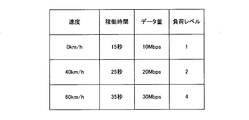
- FIG. 4 is a diagram showing an example of state information used in the in-vehicle device according to the first embodiment of the present disclosure.
- the processing unit 21 periodically or irregularly sets a load level indicating the processing load of its own in-vehicle device 101.
- the processing unit 21 classifies each combination (hereinafter, also referred to as a set) of various information included in the state information in the storage unit 24 into a plurality of load levels.
- the processing unit 21 selects a plurality of reference sets for each load level to be classified.
- the processing unit 21 creates, for example, a determination model which is an example of a machine learning model.
- the determination model can determine the load level of its own in-vehicle device 101 based on the speed, the number of operations, the operation time, and the amount of data of the vehicle 1 indicated by the state information.
- the judgment model is an algorithm automatically created by machine learning.
- the processing unit 21 creates a learning data set using a plurality of selected sets in order to create a determination model, and stores the created learning data set in the storage unit 24.
- the processing unit 21 acquires, for example, the learning data set from the storage unit 24, and inputs the acquired learning data set to the multi-layered neural network according to the method of deep learning.
- the processing unit 21 creates and creates a determination model by causing the multi-layered neural network to perform machine learning so that the load level of its own in-vehicle device 101 can be determined based on various information included in the state information.
- the determined determination model is stored in the storage unit 24.
- the determination model can determine the load level based on, for example, the input state information.
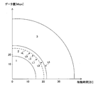
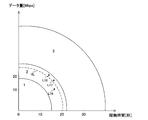
- FIG. 5 is a diagram showing an example of the determination content of the load level in the in-vehicle device according to the first embodiment of the present disclosure.
- the horizontal axis shows the operating time in the state information
- the vertical axis shows the amount of data in the state information.
- FIG. 5 shows the load level when the speed of the vehicle 1 is 40 km / h.
- the load level is determined to be 1.
- the load level is determined to be 2.
- the load level is determined to be 3.
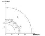
- FIG. 6 is a diagram showing another example of the determination content of the load level in the in-vehicle device according to the first embodiment of the present disclosure.
- the horizontal axis shows the number of operations or the operation time in the state information
- the vertical axis shows the amount of data in the state information.
- FIG. 6 shows the load level when the speed of the vehicle 1 is 60 km / h.
- the load level is determined to be 1.
- the load level is determined to be 3.
- the load level is determined to be 4.
- the determination content of the load level differs depending on the speed of the vehicle 1. More specifically, the higher the speed of the vehicle 1, the finer the load level is classified.
- the determination model is not limited to a configuration in which the load level is determined based on the operating time and the amount of data in the state information, and may be a configuration in which the load level is determined based on the number of operating hours and the amount of data.
- the allocation unit 23 predicts the processing load related to the target processing of its own in-vehicle device 101 based on the state information.
- the allocation unit 23 acquires the determination model created by the processing unit 21 from the storage unit 24, uses the acquired determination model, and based on the state information received from the acquisition unit 22, the in-vehicle device 101. To determine the load level of.
- the allocation unit 23 inputs the state information received from the acquisition unit 22 into the determination model.
- the judgment model When the state information is input, the judgment model outputs, for example, the load level information which is the state information with the load level corresponding to the state information as the judgment result as the prediction result.
- FIG. 7 is a diagram showing an example of load level information used in the in-vehicle device according to the first embodiment of the present disclosure.
- the load level is "1" when the speed of the vehicle 1 is "0 km / h", the operating time is “15 seconds”, and the amount of data is “10 Mbps”.
- the speed of the vehicle 1 is "40 km / h”
- the operating time is "25 seconds”
- the amount of data is "20 Mbps”
- the load level is "2”.
- the speed of the vehicle 1 is "60 km / h”
- the operating time is "35 seconds”
- the amount of data is "30 Mbps”
- the load level is "3".
- the allocation unit 23 determines the number of available physical resources according to the state indicated by the state information acquired by the acquisition unit 22. Then, the allocation unit 23 changes the allocation of physical resources used for the target process, which is one or a plurality of types of processes to be performed by the in-vehicle device 101.
- the allocation unit 23 changes the allocation of the physical resources used for the target process according to the prediction result based on the state information acquired by the acquisition unit 22.
- the allocation unit 23 determines the number of physical resources allocated to the target process, for example, based on the allocation information stored in the storage unit 24.
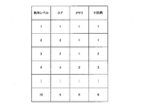
- FIG. 8 is a diagram showing an example of allocation information used in the in-vehicle device according to the first embodiment of the present disclosure.
- the allocation information shows the correspondence between the load level and the physical resources allocated to the target process. For example, when the load level is 1, the number of cores 31 allocated is 1, the number of memories 32 is 1, and the number of IF circuits 33 is 1.
- the allocation unit 23 determines the number of physical resources corresponding to the prediction result, that is, the load level indicated by the load level information in the allocation information, as the number of physical resources allocated to the target process.
- the allocation unit 23 determines the number of cores 31 to be allocated to 2, the number of memories 32 to 1, and the number of IF circuits 33. Is determined to 2.
- the allocation unit 23 changes the number of physical resources allocated to the target process. .. That is, the allocation unit 23 allocates the determined number of physical resources to the target process.
- the allocation unit 23 changes a state in which a plurality of physical resources are allocated to a plurality of types of processes to a plurality of types of processes in which a number of physical resources smaller than the number of physical resources allocated to the plurality of types of processes is assigned. It is possible to switch to the assigned state.
- the allocation unit 23 reduces the number of cores 31 assigned to the target process to 2.
- the allocation unit 23 outputs an instruction to the OS 34 to reduce the number of cores 31 allocated to the target process from 3 to 2, for example.
- the OS 34 reduces the number of cores 31 assigned to the target process from 3 to 2 according to the instruction received from the allocation unit 23.
- the OS 34 for example, when software SW1 and software SW5 are assigned to core 31A, software SW2 and software SW3 are assigned to core 31B, and software SW4 is assigned to core 31C, software is assigned to core 31A.
- software SW1 and software SW5 are assigned to core 31A
- software SW2 and software SW3 are assigned to core 31B
- software SW4 is assigned to core 31C
- software is assigned to core 31A.
- the number of cores 31 assigned to the target process is reduced from 3 to 2.
- the allocation unit 23 stops at least one of power supply and clock supply to the physical resources that are not allocated to the target process.
- the allocation unit 23 is at least one of power supply and clock supply to the cores 31 that are not assigned. Stop one.
- the allocation unit 23 for example, in addition to the instruction to reduce the number of cores 31 allocated to the target process from 3 to 2, at least power supply and clock supply to the cores 31 that are not allocated.
- a stop instruction to stop one of them is output to the OS 34.
- the OS 34 performs a process of stopping at least one of the power supply and the clock supply to the core 31 which is out of the allocation according to the stop instruction received from the allocation unit 23.
- the OS 34 sets, for example, the value of a register or the like in the processing unit 21 so as to stop at least one of the power supply and the clock supply to the core 31.
- the processing unit 21 switches at least one of the switch 37 connected between the core 31 and the clock generation circuit 35 and the switch 37 connected between the core 31 and the power supply 36. By turning it off, at least one of the power supply and the clock supply to the core 31 is stopped.
- the allocation unit 23 may be configured to execute the allocation change when the state in which the physical resource allocation should be changed continues for a predetermined time.
- FIG. 9 is a diagram showing an example of physical resource allocation according to the load level by the in-vehicle device according to the first embodiment of the present disclosure.
- the allocation unit 23 determines the load level indicated by the prediction result, that is, the load level information, as the load level 3 based on the state information L1 at a certain timing.
- the allocation unit 23 determines to maintain the number of physical resources allocated to the target process to the number of physical resources corresponding to the load level 3.
- the allocation unit 23 determines the load level as the load level 2 based on the state information L2 at the next timing.
- the allocation unit 23 corresponds the number of physical resources allocated to the target process to the prediction result, that is, the load level 2 indicated by the load level information. Decide to maintain the number of physical resources corresponding to load level 3 rather than the number of physical resources.
- the allocation unit 23 determines the load level as the load level 2 based on the state information L3 at the next timing.
- the allocation unit 23 corresponds the number of physical resources allocated to the target process to the prediction result, that is, the load level 2 indicated by the load level information. Decide to maintain the number of physical resources corresponding to load level 3 rather than the number of physical resources.
- the allocation unit 23 determines the load level as the load level 2 based on the state information L4 at the next timing.
- the allocation unit 23 determines the number of physical resources allocated to the target process for the physical resources corresponding to the load level 2. Decide on a number.
- the allocation unit 23 refers to the allocation information shown in FIG. 8, for example, and since the determined number of physical resources is different from the current number of physical resources allocated to the target process, the physical resource allocated to the target process. Change the number of.
- the allocation unit 23 in the in-vehicle device 101 may be configured to provide hysteresis when reducing the number of physical resources allocated to the target process.
- the allocation unit 23 executes the allocation change when the state in which the physical resource allocation should be changed continues for a predetermined time.
- FIG. 10 is a diagram showing an example of the determination content of the load level provided with hysteresis in the in-vehicle device according to the first embodiment of the present disclosure.
- the allocation unit 23 determines the load level indicated by the prediction result, that is, the load level information, as the load level 3 based on the state information L5 at a certain timing.
- the allocation unit 23 determines to maintain the number of physical resources allocated to the target process to the number of physical resources corresponding to the load level 3.
- the allocation unit 23 determines the load level as the load level 2 based on the state information L6 at the next timing. At this time, the allocation unit 23 determines that the state information L6 is in a state exceeding the hysteresis HL.
- the allocation unit 23 determines the number of physical resources allocated to the target process, not the number of physical resources corresponding to the load level 2 indicated by the prediction result, that is, the load level information, but the number of physical resources corresponding to the load level 3. Decide to keep in.
- the allocation unit 23 determines the load level as the load level 2 based on the state information L7 at the next timing. At this time, the allocation unit 23 determines that the state information L7 is below the hysteresis HL.
- the allocation unit 23 determines the number of physical resources allocated to the target process, that is, the physical corresponding to the load level 2 indicated by the prediction result, that is, the load level information. Decide to maintain the number of physical resources corresponding to load level 3 rather than the number of resources.
- the allocation unit 23 determines the load level as the load level 2 based on the state information L8 at the next timing, and further determines the load level as the load level 2 based on the state information L9 at the next timing. .. At this time, the allocation unit 23 determines that the state information L8 and the state information L9 are in a state below the hysteresis HL.
- the allocation unit 23 determines the number of physical resources allocated to the target process of the physical resources corresponding to the load level 2. Decide on a number.
- the allocation unit 23 refers to the allocation information shown in FIG. 8, for example, and since the determined number of physical resources is different from the current number of physical resources allocated to the target process, the physical resource allocated to the target process. Change the number of.
- FIG. 11 is a diagram showing an example of the determination content of the load level provided with a plurality of hysteresiss in the in-vehicle device according to the first embodiment of the present disclosure.
- a hysteresis HLU and a hysteresis HLD are provided.
- the allocation unit 23 determines the load level indicated by the prediction result, that is, the load level information, as the load level 3 based on the state information L10 at a certain timing. Here, the allocation unit 23 determines to maintain the number of physical resources allocated to the target process to the number of physical resources corresponding to the load level 3.
- the allocation unit 23 determines the load level 2 based on the state information L11 at the next timing. At this time, the allocation unit 23 determines that the state information L11 is below the hysteresis HLU and exceeds the hysteresis HLD.
- the allocation unit 23 determines the number of physical resources allocated to the target process, not the number of physical resources corresponding to the load level 2 indicated by the prediction result, that is, the load level information, but the number of physical resources corresponding to the load level 3. Decide to keep in.
- the allocation unit 23 determines the load level as the load level 2 based on the state information L12 at the next timing. At this time, the allocation unit 23 determines that the state information L12 is below the hysteresis HLD.
- the allocation unit 23 determines the number of physical resources allocated to the target process to the number of physical resources corresponding to the determined load level 2.
- the allocation unit 23 refers to the allocation information shown in FIG. 8, for example, and since the determined number of physical resources is different from the current number of physical resources allocated to the target process, the physical resource allocated to the target process. Change the number of.
- the allocation unit 23 can switch from a state in which a plurality of physical resources are allocated to a plurality of types of processes to a state in which a larger number of physical resources are allocated to the plurality of types of processes.
- the allocation unit 23 increases the number of cores 31 assigned to the target process to 3.
- the allocation unit 23 outputs an instruction to the OS 34 to increase the number of cores 31 allocated to the target process from 2 to 3, for example.
- the OS 34 increases the number of cores 31 assigned to the target process from 2 to 3 according to the instruction received from the allocation unit 23.
- the allocation unit 23 starts at least one of power supply and clock supply to the physical resource to which the target process is newly allocated.
- the allocation unit 23 supplies at least one of the power supply and the clock supply to the newly allocated cores 31. Start one.
- the allocation unit 23 for example, in addition to the instruction to increase the number of cores 31 allocated to the target process from 2 to 3, supplies power and clocks to the newly allocated cores 31.
- a start instruction to start at least one of them is output to the OS 34.
- the OS 34 performs a process of starting at least one of power supply and clock supply to the newly assigned core 31 according to the start instruction received from the allocation unit 23.
- the OS 34 sets, for example, the values of registers and the like in the processing unit 21 so as to supply power and clock to the core 31.
- the processing unit 21 turns on the switch 37 connected between the core 31 and the clock generation circuit 35, and the switch 37 connected between the core 31 and the power supply 36. Power supply and clock supply to the core 31 are performed.
- the allocation unit 23 may be configured to execute the allocation change when the state in which the physical resource allocation should be changed continues for a predetermined time.
- FIG. 12 is a diagram showing another example of how the vehicle-mounted device according to the first embodiment of the present disclosure determines the allocation of physical resources according to the load level.
- the allocation unit 23 determines the load level indicated by the prediction result, that is, the load level information, as the load level 2 based on the state information L13 at a certain timing. Here, the allocation unit 23 determines to maintain the number of physical resources allocated to the target process to the number of physical resources corresponding to the load level 2.
- the allocation unit 23 determines the load level as the load level 3 based on the state information L14 at the next timing.
- the allocation unit 23 corresponds to the number of physical resources allocated to the target process according to the prediction result, that is, the load level 3 indicated by the load level information. Decide to maintain the number of physical resources corresponding to load level 2 rather than the number of physical resources.
- the allocation unit 23 determines the load level as the load level 3 based on the state information L15 at the next timing.
- the allocation unit 23 determines the number of physical resources allocated to the target process for the physical resources corresponding to the load level 2. Decide on a number.
- the allocation unit 23 refers to the allocation information shown in FIG. 8, for example, and since the determined number of physical resources is different from the current number of physical resources allocated to the target process, the physical resource allocated to the target process. Change the number of. [Example 5 of changing physical resource allocation]
- the allocation unit 23 in the in-vehicle device 101 may be configured to provide hysteresis when increasing the number of physical resources allocated to the target process.
- the allocation unit 23 executes the allocation change when the state in which the physical resource allocation should be changed continues for a predetermined time, as in the change example 4.
- FIG. 13 is a diagram showing another example of the determination content of the load level provided with hysteresis in the in-vehicle device according to the first embodiment of the present disclosure.
- the allocation unit 23 determines the load level indicated by the prediction result, that is, the load level information, as the load level 2 based on the state information L16 at a certain timing. At this time, the allocation unit 23 determines that the state information L16 is below the hysteresis HL.
- the allocation unit 23 determines the load level as the load level 2 based on the state information L17 at the next timing, and further determines the load level as the load level 2 based on the state information L18 at the next timing. .. At this time, the allocation unit 23 determines that the state information L17 and the state information L18 are in a state exceeding the hysteresis HL.
- the allocation unit 23 corresponds to the number of physical resources allocated to the target process according to the prediction result, that is, the load level 2 indicated by the load level information. It is determined not by the number of physical resources but by the number of physical resources corresponding to the load level 3.
- the allocation unit 23 refers to the allocation information shown in FIG. 8, for example, and since the determined number of physical resources is different from the current number of physical resources allocated to the target process, the physical resource allocated to the target process. Change the number of.
- FIG. 14 is a diagram showing an example of the determination content of the load level provided with a plurality of hysteresiss in the in-vehicle device according to the first embodiment of the present disclosure.
- a hysteresis HLU and a hysteresis HLD are provided.
- the allocation unit 23 determines the load level indicated by the prediction result, that is, the load level information, as the load level 2 based on the state information L19 at a certain timing. At this time, the allocation unit 23 determines that the state information L19 is below the hysteresis HLD.
- the allocation unit 23 determines the load level 2 based on the state information L20 at the next timing. At this time, the allocation unit 23 determines that the state information L20 is below the hysteresis HLU and exceeds the hysteresis HLD.
- the allocation unit 23 determines the load level as the load level 2 based on the state information L21 at the next timing. At this time, the allocation unit 23 determines that the state information L21 is in a state exceeding the hysteresis HLU.
- the allocation unit 23 determines the number of physical resources allocated to the target process, not the number of physical resources corresponding to the load level 2 indicated by the prediction result, that is, the load level information, but the number of physical resources corresponding to the load level 3. To decide.
- the allocation unit 23 refers to the allocation information shown in FIG. 8, for example, and since the determined number of physical resources is different from the current number of physical resources allocated to the target process, the physical resource allocated to the target process. Change the number of.
- the allocation of physical resources may be changed based on the degree of consumption of physical resources.
- the acquisition unit 22 further acquires a plurality of consumption information regarding the degree of consumption of each of the plurality of physical resources.
- the acquisition unit 22 monitors the operating time of each of the core 31, the memory 32, and the IF circuit 33. Specifically, the acquisition unit 22 creates, for example, consumption information indicating the operating time for each physical resource at predetermined time intervals and stores it in the storage unit 24.
- the consumption information may be information based on the operating time. More specifically, the consumption information includes, for example, the operating time acquired by the acquisition unit 22 and the power consumption and life of the physical resource corresponding to the operating time when the power consumption and life are different for each physical resource. The degree of consumption calculated based on this may be indicated.
- FIG. 15 is a diagram showing an example of consumption information used in the in-vehicle device according to the first embodiment of the present disclosure.
- the operating time of the core 31A is 100 hours
- the operating time of the core 31B is 200 hours
- the operating time of the core 31C is 50 hours
- the operating time of the memory 32A is 100 hours.
- the operating time of the IF circuit 33A is 100 hours.
- the allocation unit 23 changes the physical resource allocation based on the consumption information acquired by the acquisition unit 22.
- the allocation unit 23 outputs to the OS 34 an instruction to reduce the number of cores 31 assigned to the target process, including information indicating the core 31 to be unassigned to the target process.
- the allocation unit 23 refers to the consumption information in the storage unit 24 and allocates the cores 31 in order from the core 31 having the longest operating time included in the consumption information. remove.
- the allocation unit 23 instructs the core 31B, which is the core 31 having the longest operating time included in the consumption information shown in FIG. Include in.
- the allocation unit 23 outputs to the OS 34, for example, in the instruction to increase the number of cores 31 assigned to the target process, including information indicating the core 31 to which the target process is newly allocated.
- the allocation unit 23 allocates the cores 31 included in the consumption information in order from the shortest operating time by referring to the consumption information in the storage unit 24.
- the allocation unit 23 instructs the core 31C, which is the core 31 having the shortest operating time included in the consumption information shown in FIG. Include in.
- Each device in the in-vehicle communication system includes a computer including a memory, and an arithmetic processing unit such as a CPU in the computer is a program including a part or all of each step of the following sequence or flowchart. Are read from the memory and executed.
- the programs of these plurality of devices can be installed from the outside.
- the programs of these plurality of devices are distributed in a state of being stored in a recording medium.
- FIG. 16 is a flowchart defining an operation procedure when the in-vehicle device according to the first embodiment of the present disclosure manages its own physical resources.
- the in-vehicle device 101 acquires state information indicating the state of the vehicle 1 (step S101).
- the in-vehicle device 101 determines its own load level based on the acquired state information. That is, the in-vehicle device 101 predicts its own processing load (step S102).
- the in-vehicle device 101 changes the allocation of the physical resources used for the target processing according to the prediction result, that is, the determined load level. More specifically, the in-vehicle device 101 changes the physical resource allocation when the determined load level is different from its own current load level (YES in step S103).
- the in-vehicle device 101 may provide hysteresis in a state in which the allocation should be changed, or may change the allocation when the state in which the allocation should be changed continues for a predetermined time (step S104).
- the in-vehicle device 101 switches to a state in which a larger number of physical resources are allocated to the target process. At this time, the in-vehicle device 101 is assigned in order from the core 31 having the shortest operating time included in the consumption information (step S105). Then, the in-vehicle device 101 acquires the state information at the next timing (step S101).
- the in-vehicle device 101 switches to a state in which a smaller number of physical resources are allocated to the target process.
- the in-vehicle device 101 is, for example, unassigned in order from the core 31 having the longest operating time included in the consumption information (step S106). Then, the in-vehicle device 101 acquires the state information at the next timing (step S101).
- the in-vehicle device 101 acquires the state information at the next timing without changing the physical resource allocation. (Step S101).
- the allocation unit 23 is configured to predict the processing load related to the target processing of its own in-vehicle device 101 based on the state information. It is not limited to this.
- the allocation unit 23 may be configured not to predict the processing load. More specifically, the allocation unit 23 may be configured to change the allocation of physical resources based on the state information without determining the load level, for example.
- the allocation unit 23 is configured to determine the number of available physical resources according to the state indicated by the state information. It is not limited to.
- the allocation unit 23 may be configured so as not to determine the number of available physical resources.
- the allocation unit 23 outputs, for example, an instruction to increase or decrease the physical resources allocated to the target process to the OS 34 without determining the number of physical resources.
- the in-vehicle device 101 is configured to stop at least one of power supply and clock supply to physical resources that are not assigned to the target process. It is not limited. The in-vehicle device 101 may be configured so as not to stop the power supply and the clock supply to the physical resource.
- the in-vehicle device 101 is defined as a central gateway as an example, but the present invention is not limited to this.
- the in-vehicle device 101 may be, for example, an electronic control unit different from the central gateway.
- the power consumption of the in-vehicle device increases as the number of applications that the in-vehicle device should provide increases. Such an increase in power consumption has a large effect on, for example, the cruising range of an electric vehicle.
- the acquisition unit 22 acquires the state information indicating the state of the vehicle 1.
- the allocating unit 23 changes the allocation of physical resources used for the target processing, which is one or a plurality of types of processing to be performed by its own in-vehicle device 101, according to the state indicated by the state information acquired by the acquiring unit 22.
- the allocation of the physical resources to be executed for the target processing is changed for the plurality of physical resources in the in-vehicle device 101 according to the state of the vehicle 1. It is possible to select an appropriate physical resource and perform the target processing.
- the allocation unit 23 predicts the processing load of its own in-vehicle device 101 based on the state information, and allocates physical resources according to the prediction result. change.
- the allocation unit 23 determines the number of available physical resources according to the state indicated by the state information, and targets the determined number of physical resources. Assign to processing.
- the number of usable physical resources can be increased or decreased according to the state of the vehicle 1, so that the power consumption can be reduced more effectively.
- the allocation unit 23 sets a state in which a plurality of physical resources are allocated to a plurality of types of processing to be performed by the vehicle-mounted device 101. It is possible to switch to a state in which a number of physical resources less than the number of physical resources allocated to the processing of the above is allocated to the plurality of types of processing.
- the allocation unit 23 when the number of physical resources allocated to the target process is reduced, the allocation unit 23 supplies power and clocks to the physical resources that are not allocated to the target process. Stop at least one of the above.
- the allocation unit 23 provides hysteresis depending on whether the number of physical resources allocated to the target process is decreased or increased, or the physical resources are allocated. Executes the assignment change when the state in which the assignment should be changed continues for a predetermined time.
- the acquisition unit 22 acquires a plurality of consumption information regarding the degree of consumption of each of the plurality of physical resources.
- the allocation unit 23 changes the physical resource allocation based on each consumption information acquired by the acquisition unit 22.
- the state information indicating the state of the vehicle 1 is acquired.
- the allocation of physical resources used for the target process which is one or a plurality of types of processes to be performed by the in-vehicle device 101, is changed according to the state indicated by the acquired state information.
- the allocation of the physical resources to be executed for the target processing is changed for the plurality of physical resources in the in-vehicle device 101 according to the state of the vehicle 1. It is possible to select an appropriate physical resource and perform the target processing.
- the present embodiment relates to an in-vehicle device in which the processing load of the in-vehicle device is predicted outside the in-vehicle device as compared with the in-vehicle device according to the first embodiment. Except for the contents described below, the device is the same as the in-vehicle device according to the first embodiment.
- FIG. 17 is a diagram showing a configuration of a vehicle management system according to a second embodiment of the present disclosure.
- the vehicle management system 401 includes an in-vehicle communication system 302 and a management device 201.
- the in-vehicle communication system 302 includes an in-vehicle device 102 instead of the in-vehicle device 101 as compared with the in-vehicle communication system 301 shown in FIG.
- the in-vehicle device 102 and the management device 201 are, for example, servers.
- the configuration of the functional block of the in-vehicle device 102 is the same as that of the in-vehicle device 101 shown in FIG.
- the in-vehicle device 102 further performs wireless communication processing with the wireless base station device 161 according to a communication standard such as LTE (Long Term Evolution) or 4G or 5G, as compared with the in-vehicle device 101 shown in FIG.
- Software SW6 (not shown) having the function of TCU (Telematics Communication Unit) is installed.
- the software SW6 functions as the communication unit 25 shown in FIG.
- the in-vehicle device 102 can communicate with the management device 201 outside the vehicle 1 via the wireless base station device 161 by using the software SW6.
- the communication unit 25 in the in-vehicle device 102 transmits the state information indicating the state of the vehicle 1 to the management device 201.
- the acquisition unit 22 in the in-vehicle device 102 creates, for example, the above-mentioned state information and outputs it to the processing unit 21.
- the processing unit 21 transmits the state information received from the acquisition unit 22 to the management device 201 via the communication unit 25 and the wireless base station device 161 by wireless communication.
- the management device 201 receives the state information transmitted from the in-vehicle device 102, and stores the received state information in a storage unit (not shown).
- the management device 201 predicts the processing load of the vehicle-mounted device 102 based on the state information received from the vehicle-mounted device 102.
- the management device 201 creates a determination model which is an example of a machine learning model, similarly to the processing unit 21 in the in-vehicle device 101.
- the management device 201 determines the load level of the vehicle-mounted device 102 based on the state information received from the vehicle-mounted device 102 by using the created determination model, similarly to the allocation unit 23 in the vehicle-mounted device 101.
- the management device 201 transmits, for example, load level information to the in-vehicle device 102 as load information indicating the prediction result.
- the communication unit 25 in the in-vehicle device 102 receives the load level information transmitted from the management device 201 via the wireless base station device 161 and outputs the received load level information to the processing unit 21.
- the processing unit 21 outputs the load level information received from the communication unit 25 to the allocation unit 23.
- the allocation unit 23 determines the number of physical resources allocated to the target process based on the load level information received from the processing unit 21 and the allocation information in the storage unit 24, and changes the allocation of the physical resources used for the target process. To do.
- FIG. 18 is a diagram showing a sequence for managing physical resources in an in-vehicle device in the vehicle management system according to the second embodiment of the present disclosure.
- the in-vehicle device 102 acquires the state information indicating the state of the vehicle 1 (step S201).
- the in-vehicle device 102 transmits the acquired state information to the management device 201 (step S202).
- the management device 201 receives the state information transmitted from the vehicle-mounted device 102, and predicts the processing load of the vehicle-mounted device 102 based on the received state information. That is, the management device 201 determines the load level of the in-vehicle device 102 based on the received state information (step S203).
- the management device 201 transmits, for example, load level information to the in-vehicle device 102 as load information indicating the prediction result (step S204).
- the in-vehicle device 102 changes the allocation of the physical resources used for the target processing according to the prediction result indicated by the load information. More specifically, the in-vehicle device 102 receives the load level information transmitted from the management device 201, determines the number of physical resources allocated to the target process based on the received load level information, and uses the load level information for the target process. The allocation of physical resources to be obtained is changed (step S205).
- the in-vehicle device 102 and the management device 201 repeat the same operations as in steps S201 to S205.
- the in-vehicle device 102 includes a plurality of physical resources.
- the in-vehicle device 102 transmits the state information indicating the state of the vehicle 1 to the management device 201.
- the management device 201 predicts the processing load of the vehicle-mounted device 102 based on the state information received from the vehicle-mounted device 102, and transmits the load information indicating the prediction result to the vehicle-mounted device 102.
- the in-vehicle device 102 changes the allocation of physical resources used for the target process, which is one or a plurality of types of processes to be performed by the in-vehicle device 102, according to the prediction result indicated by the load information received from the management device 201.
- the allocation of the physical resources to be executed for the target processing is changed for the plurality of physical resources in the in-vehicle device 101 according to the state of the vehicle 1. It is possible to select an appropriate physical resource and perform the target processing.
- the in-vehicle device 102 transmits the state information indicating the state of the vehicle to the management device 201.
- the management device 201 predicts the processing load of the vehicle-mounted device based on the state information received from the vehicle-mounted device 102, and transmits the load information indicating the prediction result to the vehicle-mounted device 102.
- the vehicle-mounted device 102 changes the allocation of physical resources used for the target processing, which is one or a plurality of types of processing to be performed by the vehicle-mounted device 102, according to the prediction result indicated by the load information received from the management device 201. ..
- the allocation of the physical resources to be executed for the target processing is changed for the plurality of physical resources in the in-vehicle device 101 according to the state of the vehicle 1. It is possible to select an appropriate physical resource and perform the target processing.
- the allocation unit is an in-vehicle device that predicts the processing load of the in-vehicle device related to the target processing based on the state information.
- In-vehicle devices that include multiple physical resources and Equipped with a management device
- the in-vehicle device transmits state information indicating the state of the vehicle to the management device.
- the management device predicts the processing load of the vehicle-mounted device based on the state information received from the vehicle-mounted device, and transmits load information indicating the prediction result to the vehicle-mounted device.
- the in-vehicle device changes the allocation of the physical resource used for the target process, which is one or a plurality of types of processes to be performed by the in-vehicle device, according to the prediction result indicated by the load information received from the management device.
- the vehicle-mounted device is a vehicle management system that predicts the processing load of the vehicle-mounted device related to the target processing based on the state information.
- Vehicle 10 CAN Bus 11 Ethernet Cable 21 Processing Unit 22 Acquisition Unit 23 Allocation Unit 24 Storage Unit 25 Communication Unit 31, 31A, 31B, 31C, 31D Core 32, 32A, 32B Memory 33, 33A, 33B IF Circuit 34 OS 35 Clock generation circuit 36 Power supply 37 Switch 101,102 In-vehicle device 161 Wireless base station equipment 201 Management device 301 In-vehicle communication system 401 Vehicle management system
Abstract
車載装置は、車両に搭載される車載装置であって、前記車両の状態を示す状態情報を取得する取得部と、複数の物理リソースと、前記取得部によって取得された前記状態情報の示す前記状態に応じて、前記車載装置が行うべき1または複数種類の処理である対象処理に用いられる前記物理リソースの割り当てを変更する割り当て部と、を備える。
Description
本開示は、車載装置、車両管理システム、リソース管理方法およびリソース管理プログラムに関する。
この出願は、2019年7月17日に出願された日本出願特願2019-131582号を基礎とする優先権を主張し、その開示のすべてをここに取り込む。
この出願は、2019年7月17日に出願された日本出願特願2019-131582号を基礎とする優先権を主張し、その開示のすべてをここに取り込む。
たとえば、国際公開第2012/063334号(特許文献1)には、以下のようなメモリ制御装置が開示されている。すなわち、メモリ制御装置は、電子計算機とI/O装置が接続され、前記電子計算機のメモリの特定領域をページに分割し、分割されたページごとにメモリ書き込みの有無を記憶するためのdirty bit配列と、I/O装置からの電子計算機のメモリに対するメモリ書き込みを監視するメモリ書き込み監視機構を有し、前記監視機構によって、前記メモリの特定領域に対するI/O装置からのメモリ書き込みが観測された時に、メモリ書き込みのアドレスからメモリ書き込みの行われたページを決定し、前記dirty bit配列に前記ページに対するメモリ書き込みがあったことを記録する。
また、特表2014-510357号公報(特許文献2)には、以下のような方法が開示されている。すなわち、ポータブルコンピューティングデバイスにおいて、処理負荷の並行処理度を動的に判断し、処理負荷をサポートするコアの数を自動的に調整するための方法であって、マルチコアプロセッサの1つまたは複数の処理待ち行列を監視するステップと、前記マルチコアプロセッサの現在の動作モードおよび前記1つまたは複数の処理待ち行列の前記監視に基づいて、並行処理の割合を計算するステップと、並行処理の前記計算された割合に基づいて、前記マルチコアプロセッサの前記現在の動作モードを変更すべきかどうかを判断するステップと、前記マルチコアプロセッサの前記現在の動作モードを変更すべきであると判断された場合に、前記マルチコアプロセッサの1つまたは複数のコアに対し、ダイナミック電圧および周波数スケーリングアルゴリズムをスイッチングするよう命令するステップとを含む。
本開示の車載装置は、車両に搭載される車載装置であって、前記車両の状態を示す状態情報を取得する取得部と、複数の物理リソースと、前記取得部によって取得された前記状態情報の示す前記状態に応じて、前記車載装置が行うべき1または複数種類の処理である対象処理に用いられる前記物理リソースの割り当てを変更する割り当て部と、を備える。
本開示の車両管理システムは、車両に搭載され、複数の物理リソースを含む車載装置と、管理装置とを備え、前記車載装置は、前記車両の状態を示す状態情報を前記管理装置へ送信し、前記管理装置は、前記車載装置から受信した前記状態情報に基づいて、前記車載装置の処理負荷を予測し、予測結果を示す負荷情報を前記車載装置へ送信し、前記車載装置は、前記管理装置から受信した前記負荷情報の示す前記予測結果に応じて、前記車載装置が行うべき1または複数種類の処理である対象処理に用いられる前記物理リソースの割り当てを変更する。
本開示のリソース管理方法は、車両に搭載され、複数の物理リソースを備える車載装置におけるリソース管理方法であって、前記車両の状態を示す状態情報を取得するステップと、取得した前記状態情報の示す前記状態に応じて、前記車載装置が行うべき1または複数種類の処理である対象処理に用いられる前記物理リソースの割り当てを変更するステップとを含む。
本開示のリソース管理方法は、車両に搭載される車載装置であって複数の物理リソースを含む車載装置と、管理装置とを備える車両管理システムにおけるリソース管理方法であって、前記車載装置が、前記車両の状態を示す状態情報を前記管理装置へ送信するステップと、前記管理装置が、前記車載装置から受信した前記状態情報に基づいて、前記車載装置の処理負荷を予測し、予測結果を示す負荷情報を前記車載装置へ送信するステップと、前記車載装置が、前記管理装置から受信した前記負荷情報の示す前記予測結果に応じて、前記車載装置が行うべき1または複数種類の処理である対象処理に用いられる前記物理リソースの割り当てを変更するステップとを含む。
本開示のリソース管理プログラムは、車両に搭載される車載装置であって複数の物理リソースを備える車載装置において用いられるリソース管理プログラムであって、コンピュータを、前記車両の状態を示す状態情報を取得する取得部と、前記取得部によって取得された前記状態情報の示す前記状態に応じて、前記車載装置が行うべき1または複数種類の処理である対象処理に用いられる前記物理リソースの割り当てを変更する割り当て部、として機能させるためのプログラムである。
本開示のリソース管理プログラムは、車両に搭載される車載装置であって複数の物理リソースを含む車載装置と管理装置とを備える車両管理システムにおける、前記車載装置において用いられるリソース管理プログラムであって、コンピュータを、前記車両の状態を示す状態情報を前記管理装置へ送信し、前記管理装置によって前記車載装置から受信した前記状態情報に基づいて予測された、前記車載装置の処理負荷の予測結果を示す負荷情報を前記管理装置から受信する通信部と、前記通信部によって受信された前記管理装置からの前記負荷情報の示す前記予測結果に応じて、前記車載装置が行うべき1または複数種類の処理である対象処理に用いられる前記物理リソースの割り当てを変更する割り当て部、として機能させるためのプログラムである。
本開示の一態様は、このような特徴的な処理部を備える車載装置として実現され得るだけでなく、車載装置の一部または全部を実現する半導体集積回路として実現され得る。
本開示の一態様は、このような特徴的な処理部を備える車両管理システムとして実現され得るだけでなく、かかる特徴的な処理のステップをコンピュータに実行させるためのプログラムとして実現され得る。また、本開示の一態様は、車両管理システムの一部または全部を実現する半導体集積回路として実現され得る。
[本開示が解決しようとする課題]
デバイスの進化に伴い、車両において、複数のECU(Electronic Control Unit)の機能統合が進んでいく、すなわち、1つの車載装置が複数のアプリケーションを提供するようになっていくと考えられる。
デバイスの進化に伴い、車両において、複数のECU(Electronic Control Unit)の機能統合が進んでいく、すなわち、1つの車載装置が複数のアプリケーションを提供するようになっていくと考えられる。
車載装置の消費電力は、車載装置が提供すべきアプリケーションの増加に伴って増加する。このような消費電力の増加は、たとえば、電気自動車の航続距離に与える影響が大きい。
本開示は、上述の課題を解決するためになされたもので、その目的は、車載装置において、必要な処理を実行しながら消費電力を効果的に低減することが可能な車載装置、車両管理システム、リソース管理方法およびリソース管理プログラムを提供することである。
[本開示の効果]
本開示によれば、車載装置において、必要な処理を実行しながら消費電力を効果的に低減することができる。
本開示によれば、車載装置において、必要な処理を実行しながら消費電力を効果的に低減することができる。
[本開示の実施形態の説明]
最初に、本開示の実施形態の内容を列記して説明する。
最初に、本開示の実施形態の内容を列記して説明する。
(1)本開示の実施の形態に係る車載装置は、車両に搭載される車載装置であって、前記車両の状態を示す状態情報を取得する取得部と、複数の物理リソースと、前記取得部によって取得された前記状態情報の示す前記状態に応じて、前記車載装置が行うべき1または複数種類の処理である対象処理に用いられる前記物理リソースの割り当てを変更する割り当て部と、を備える。
このように、車載装置を搭載する車両の状態に応じて、車載装置における複数の物理リソースについて、対象処理を実行させるべき物理リソースの割り当てを変更する構成により、車両の状態に応じて適切な物理リソースを選択し、対象処理を行わせることができる。したがって、車載装置において、必要な処理を実行しながら消費電力を効果的に低減することができる。
(2)好ましくは、前記割り当て部は、前記状態情報に基づいて、前記車載装置の処理負荷を予測し、予測結果に応じて前記割り当てを変更する。
このような構成により、車両の状態から予測される車載装置の処理負荷を考慮した、より適切な割り当て内容を決定することができる。すなわち、物理リソースの割り当てを、車両の状態に応じて増減する対象処理の負荷に追随させることができる。
(3)好ましくは、前記割り当て部は、前記状態情報の示す前記状態に応じて、使用可能な前記物理リソースの数を決定し、決定した数の前記物理リソースを前記対象処理に割り当てる。
このような構成により、使用可能な物理リソースの数を車両の状態に応じて増減させることができるため、消費電力をより効果的に削減することができる。
(4)好ましくは、前記割り当て部は、前記車載装置が行うべき複数種類の処理に複数の前記物理リソースが割り当てられている状態を、前記複数種類の処理に割り当てられている前記物理リソースの数より少ない数の前記物理リソースが前記複数種類の処理に割り当てられる状態へ切り替え可能である。
このような構成により、複数種類の処理の一部または全部を、変更前と比べて共通の物理リソースにまとめることができるため、物理リソースのより効率的な使用が可能となる。また、複数種類の処理をそれぞれ実行する複数のアプリケーション間において実行タイミングの調停を行う必要がなくなり、アプリケーションに調停機能を追加することなく容易に消費電力の低減を実現することができる。
(5)好ましくは、前記割り当て部は、前記対象処理に割り当てる前記物理リソースの数を減少させる場合、前記対象処理の割り当てから外れる前記物理リソースへの電力供給およびクロック供給の少なくともいずれか一方を停止する。
このような構成により、未使用の物理リソースの消費電力をより大きく削減することができる。
(6)好ましくは、前記割り当て部は、前記対象処理に割り当てる前記物理リソースの数を減少させる場合と増加させる場合とにおいてヒステリシスを設けるか、または、前記物理リソースの割り当てを変更すべき前記状態が所定時間継続した場合に前記割り当ての変更を実行する。
このような構成により、物理リソースの割り当て内容が頻繁に変わる事態を抑制し、車載装置の動作をより安定化することができる。
(7)好ましくは、前記取得部は、さらに、前記複数の物理リソースの各々の消耗度に関する複数の消耗情報をそれぞれ取得し、前記割り当て部は、前記取得部によって取得された各前記消耗情報にさらに基づいて、前記物理リソースの割り当てを変更する。
このような構成により、特定の物理リソースの消耗度が大きくなることを抑制し、車載装置の使用可能時間をより長くすることができる。
(8)本開示の実施の形態に係る車両管理システムは、車両に搭載され、複数の物理リソースを含む車載装置と、管理装置とを備え、前記車載装置は、前記車両の状態を示す状態情報を前記管理装置へ送信し、前記管理装置は、前記車載装置から受信した前記状態情報に基づいて、前記車載装置の処理負荷を予測し、予測結果を示す負荷情報を前記車載装置へ送信し、前記車載装置は、前記管理装置から受信した前記負荷情報の示す前記予測結果に応じて、前記車載装置が行うべき1または複数種類の処理である対象処理に用いられる前記物理リソースの割り当てを変更する。
このように、車載装置を搭載する車両の状態に応じて、車載装置における複数の物理リソースについて、対象処理を実行させるべき物理リソースの割り当てを変更する構成により、車両の状態に応じて適切な物理リソースを選択し、対象処理を行わせることができる。したがって、車載装置において、必要な処理を実行しながら消費電力を効果的に低減することができる。
(9)本開示の実施の形態に係るリソース管理方法は、車両に搭載され、複数の物理リソースを備える車載装置におけるリソース管理方法であって、前記車両の状態を示す状態情報を取得するステップと、取得した前記状態情報の示す前記状態に応じて、前記車載装置が行うべき1または複数種類の処理である対象処理に用いられる前記物理リソースの割り当てを変更するステップとを含む。
このように、車載装置を搭載する車両の状態に応じて、車載装置における複数の物理リソースについて、対象処理を実行させるべき物理リソースの割り当てを変更する構成により、車両の状態に応じて適切な物理リソースを選択し、対象処理を行わせることができる。したがって、車載装置において、必要な処理を実行しながら消費電力を効果的に低減することができる。
(10)本開示の実施の形態に係るリソース管理方法は、車両に搭載される車載装置であって複数の物理リソースを含む車載装置と、管理装置とを備える車両管理システムにおけるリソース管理方法であって、前記車載装置が、前記車両の状態を示す状態情報を前記管理装置へ送信するステップと、前記管理装置が、前記車載装置から受信した前記状態情報に基づいて、前記車載装置の処理負荷を予測し、予測結果を示す負荷情報を前記車載装置へ送信するステップと、前記車載装置が、前記管理装置から受信した前記負荷情報の示す前記予測結果に応じて、前記車載装置が行うべき1または複数種類の処理である対象処理に用いられる前記物理リソースの割り当てを変更するステップとを含む。
このように、車載装置を搭載する車両の状態に応じて、車載装置における複数の物理リソースについて、対象処理を実行させるべき物理リソースの割り当てを変更する構成により、車両の状態に応じて適切な物理リソースを選択し、対象処理を行わせることができる。したがって、車載装置において、必要な処理を実行しながら消費電力を効果的に低減することができる。
(11)本開示の実施の形態に係るリソース管理プログラムは、車両に搭載される車載装置であって複数の物理リソースを備える車載装置において用いられるリソース管理プログラムであって、コンピュータを、前記車両の状態を示す状態情報を取得する取得部と、前記取得部によって取得された前記状態情報の示す前記状態に応じて、前記車載装置が行うべき1または複数種類の処理である対象処理に用いられる前記物理リソースの割り当てを変更する割り当て部、として機能させるためのプログラムである。
このように、車載装置を搭載する車両の状態に応じて、車載装置における複数の物理リソースについて、対象処理を実行させるべき物理リソースの割り当てを変更する構成により、車両の状態に応じて適切な物理リソースを選択し、対象処理を行わせることができる。したがって、車載装置において、必要な処理を実行しながら消費電力を効果的に低減することができる。
(12)本開示の実施の形態に係るリソース管理プログラムは、車両に搭載される車載装置であって複数の物理リソースを含む車載装置と管理装置とを備える車両管理システムにおける、前記車載装置において用いられるリソース管理プログラムであって、コンピュータを、前記車両の状態を示す状態情報を前記管理装置へ送信し、前記管理装置によって前記車載装置から受信した前記状態情報に基づいて予測された、前記車載装置の処理負荷の予測結果を示す負荷情報を前記管理装置から受信する通信部と、前記通信部によって受信された前記管理装置からの前記負荷情報の示す前記予測結果に応じて、前記車載装置が行うべき1または複数種類の処理である対象処理に用いられる前記物理リソースの割り当てを変更する割り当て部、として機能させるためのプログラムである。
このように、車載装置を搭載する車両の状態に応じて、車載装置における複数の物理リソースについて、対象処理を実行させるべき物理リソースの割り当てを変更する構成により、車両の状態に応じて適切な物理リソースを選択し、対象処理を行わせることができる。したがって、車載装置において、必要な処理を実行しながら消費電力を効果的に低減することができる。
以下、本開示の実施の形態について図面を用いて説明する。なお、図中同一または相当部分には同一符号を付してその説明は繰り返さない。また、以下に記載する実施の形態の少なくとも一部を任意に組み合わせてもよい。
<第1の実施の形態>
[構成および基本動作]
図1は、本開示の第1の実施の形態に係る車載通信システムの構成を示す図である。
[構成および基本動作]
図1は、本開示の第1の実施の形態に係る車載通信システムの構成を示す図である。
図1を参照して、車載通信システム301は、車両1に搭載される複数の車載装置101を備える。
複数の車載装置101は、たとえば、CAN(Controller Area Network)(登録商標)の規格に従うCANバス10、またはイーサネット(登録商標)ケーブル11を介して互いに接続されている。一例として、車載通信システム301におけるいずれか1つの車載装置101は、セントラルゲートウェイである。車載装置101は、1または複数種類の処理である対象処理、たとえば、車両1の制御を行うための1または複数種類の各種演算処理を行う。
図2は、本開示の第1の実施の形態に係る車載装置の機能ブロック図である。
図2を参照して、車載装置101は、処理部21と、取得部22と、割り当て部23とと、記憶部24と、通信部25とを備える。
図3は、本開示の第1の実施の形態に係る車載装置のハードウェアおよびソフトウェアの構成を示す図である。
図3を参照して、車載装置101は、たとえば、複数の物理リソースとして、コア31A,31B,31C,31Dと、メモリ32A,32Bと、IF(Interface)回路33A,33Bとを備える。また、車載装置101は、クロック生成回路35と、電源36と、複数のスイッチ37とを備える。
以下、コア31A,31B,31C,31Dの各々を、コア31とも称し、メモリ32A,32Bの各々を、メモリ32とも称し、IF回路33A,33Bの各々を、IF回路33とも称する。
コア31は、図2に示す処理部21として機能し、メモリ32は、図2に示す記憶部24として機能し、IF回路33は、図2に示す通信部25として機能する。
通信部25は、CANバス10、またはイーサネットケーブル11を介して互いに接続されている車載装置101と通信を行う。
クロック生成回路35は、クロック信号を生成して複数の物理リソースへ供給するクロック供給を行う。電源36は、複数の物理リソースへ電力を供給する電力供給を行う。
処理部21は、各物理リソースとクロック生成回路35との間、および各物理リソースと電源36との間にそれぞれ接続されたスイッチ37を制御することにより、各物理リソースへのクロック供給および電力供給の制御を行う。
なお、車載装置101は、たとえば、4つのコア31に限らず、3つ以下のコア31または5つ以上のコア31を備える構成であってもよく、2つのメモリ32に限らず、1つのメモリ32または3つ以上のメモリ32を備える構成であってもよく、2つのIF回路33に限らず、1つのIF回路33または3つ以上のIF回路33を備える構成であってもよい。
また、車載装置101には、各種アプリケーションを提供するソフトウェアSW1~SW4と、OS(Operating System)34とがインストールされている。
ソフトウェアSW1~SW4は、複数種類たとえば4種類のアプリケーションを提供するための各種演算処理をそれぞれ実行する。
具体的には、ソフトウェアSW1は、たとえば、車両1におけるエンターテイメントのサービスを提供するための機器、具体的には車両1に設けられたディスプレイおよびオーディオなどを制御する処理を行う。
ソフトウェアSW2は、たとえば、天候に応じて用いられる機器、具体的にはワイパーおよびフォグランプ等を制御する処理を行う。
ソフトウェアSW3は、たとえば、車両1の車内環境に影響を与える機器、具体的にはエアコンなどを制御する処理を行う。
ソフトウェアSW4は、たとえば、エンジン制御、AT(Automatic Transmission)制御、HEV(Hybrid Electric Vehicle)制御、ブレーキ制御、シャーシ制御、ステアリング制御および計器表示制御等、車両1の走行を制御する処理を行う。
ソフトウェアSW1~SW4は、OS34を介して、コア31、メモリ32およびIF回路33の一部または全部に割り当てられ、実行される。
なお、車載装置101は、1種類のアプリケーションを提供するための1つのソフトウェアがインストールされる構成であってもよい。
すなわち、OS34は、ソフトウェアSW1~SW4を実行すべきコア31、メモリ32およびIF回路33の割り当てを決定する。
具体的には、OS34は、たとえば、コア31AにソフトウェアSW1を割り当て、コア31BにソフトウェアSW2を割り当て、コア31CにソフトウェアSW3を割り当て、コア31DにソフトウェアSW4を割り当てる。
なお、OS34は、複数のコア31に1つのソフトウェアを割り当ててもよいし、1つのコア31に複数のソフトウェアを割り当ててもよい。
[課題]
デバイスの進化に伴い、車両において、複数のECU(Electronic Control Unit)の機能統合が進んでいく、すなわち、1つの車載装置が複数のアプリケーションを提供するようになっていくと考えられる。
デバイスの進化に伴い、車両において、複数のECU(Electronic Control Unit)の機能統合が進んでいく、すなわち、1つの車載装置が複数のアプリケーションを提供するようになっていくと考えられる。
車載装置の消費電力は、車載装置が提供すべきアプリケーションの増加に伴って増加する。このような消費電力の増加は、たとえば、電気自動車の航続距離に与える影響が大きい。
また、各種演算処理を行う車載装置において、ある演算処理を行うソフトウェアが、他の演算処理を行うソフトウェアと消費電力低減のための調停処理を行うことは困難である。
そこで、本開示の第1の実施の形態に係る車載装置では、以下のような構成および動作により、上記課題を解決する。
たとえば、車載装置101において、統合される機能とは独立して、消費電力低減のためのアプリケーションを提供するソフトウェアを用いる方法が考えられる。
具体的には、車載装置101には、1または複数のアプリケーションを提供するための、自己が行うべき1または複数種類の処理である対象処理に用いられる物理リソースの割り当てを変更する処理を行うソフトウェアSW5がインストールされている。ソフトウェアSW5は、たとえば、OS34によってコア31Aに割り当てられる。
ソフトウェアSW5は、車両1の状態を監視し、監視結果に応じて、対象処理に用いられる物理リソースの割り当てを変更する処理を行う。ソフトウェアSW5は、取得部22および割り当て部23として機能する。
[車両状態の監視]
車載装置101における取得部22は、車両1の状態を示す状態情報を取得する。
車載装置101における取得部22は、車両1の状態を示す状態情報を取得する。
より詳細には、取得部22は、たとえば、処理部21における稼働中のソフトウェアの数(以下、稼働数とも称する。)および当該各ソフトウェアの稼働時間を監視する。具体的には、取得部22は、たとえば、所定時間ごとに、稼働数および稼働中の各ソフトウェアの稼働時間の最大値を示す稼働情報を作成する。
また、取得部22は、複数の物理リソース間において伝送されるデータ量を監視する。具体的には、取得部22は、たとえば、所定時間ごとに当該データ量を示すデータ量情報を作成する。
また、取得部22は、車両1の速度を監視する。具体的には、取得部22は、たとえば、処理部21によって実行されたソフトウェアSW4による演算結果として、車両1の速度を示す速度情報を処理部21から受ける。
そして、取得部22は、作成した稼働情報およびデータ量情報、ならびに処理部21から受けた速度情報の対応関係を示す状態情報を作成し、記憶部24に保存するとともに割り当て部23へ出力する。
すなわち、記憶部24には、取得部22によって作成された状態情報が蓄積される。
図4は、本開示の第1の実施の形態に係る車載装置において用いられる状態情報の一例を示す図である。
図4を参照して、車両1の速度が「0km/h」である場合、稼働数が「1」であり、稼働時間が「15秒」であり、データ量が「10Mbps」である。車両1の速度が「40km/h」である場合、稼働数が「2」であり、稼働時間が「25秒」であり、データ量が「20Mbps」である。車両1の速度が「60km/h」である場合、稼働数が「3」であり、稼働時間が「35秒」であり、データ量が「30Mbps」である。
[処理負荷の予測]
処理部21は、定期的または不定期に、自己の車載装置101の処理負荷を示す負荷レベルの設定を行う。
処理部21は、定期的または不定期に、自己の車載装置101の処理負荷を示す負荷レベルの設定を行う。
具体的には、再び図2を参照して、処理部21は、記憶部24における状態情報に含まれる各種情報の各組み合わせ(以下、セットとも称する。)を複数の負荷レベルに分類する。
より詳細には、処理部21は、分類すべき負荷レベルごとに、基準となる複数のセットを選択する。
そして、処理部21は、たとえば、機械学習のモデルの一例である判定モデルを作成する。
判定モデルは、状態情報の示す車両1の速度、稼働数、稼働時間およびデータ量に基づいて、自己の車載装置101の負荷レベルを判定可能である。判定モデルは、機械学習によって自動的に作成されるアルゴリズムである。
処理部21は、判定モデルを作成するために、選択した複数のセットを用いて学習用データセットを作成し、作成した学習用データセットを記憶部24に保存する。
そして、処理部21は、たとえば、学習用データセットを記憶部24から取得し、取得した学習用データセットをディープラーニング(Deep Learning)の手法に沿って、多層化したニューラルネットワークへ入力する。
処理部21は、多層化したニューラルネットワークに対して、状態情報に含まれる各種情報に基づいて、自己の車載装置101の負荷レベルを判定できるように機械学習させることにより判定モデルを作成し、作成した判定モデルを記憶部24に保存する。
このような機械学習の結果、判定モデルは、たとえば、入力された状態情報に基づいて、負荷レベルを判定することが可能となる。
図5は、本開示の第1の実施の形態に係る車載装置における負荷レベルの判定内容の一例を示す図である。図5において、横軸は状態情報における稼働時間を示し、縦軸は状態情報におけるデータ量を示す。図5は、車両1の速度が40km/hの場合における負荷レベルを示している。
図5を参照して、たとえば、稼働時間が「10秒」であり、データ量が「10Mbps」である場合、負荷レベルが1に判定される。
また、稼働時間が「20秒」であり、データ量が「20Mbps」である場合、負荷レベルが2に判定される。
また、稼働時間が「30秒」であり、データ量が「30Mbps」である場合、負荷レベルが3に判定される。
図6は、本開示の第1の実施の形態に係る車載装置における負荷レベルの判定内容の他の例を示す図である。図6において、横軸は状態情報における稼働数または稼働時間を示し、縦軸は状態情報におけるデータ量を示す。図6は、車両1の速度が60km/hの場合における負荷レベルを示している。
図6を参照して、たとえば、稼働時間が「10秒」であり、データ量が「10Mbps」である場合、負荷レベルが1に判定される。
また、稼働時間が「20秒」であり、データ量が「20Mbps」である場合、負荷レベルが3に判定される。
また、たとえば、稼働時間が「30秒」であり、データ量が「30Mbps」である場合、負荷レベルが4に判定される。
図5および図6に示すように、車載装置101では、車両1の速度に応じて負荷レベルの判定内容が異なる。より詳細には、車両1の速度が大きい方が、負荷レベルがより細かく分類される。
なお、判定モデルは、状態情報のうちの稼働時間およびデータ量に基づいて負荷レベルを判定する構成に限らず、稼働数およびデータ量に基づいて負荷レベルを判定する構成であってもよい。
再び図2を参照して、割り当て部23は、状態情報に基づいて、自己の車載装置101の対象処理に関する処理負荷を予測する。
より詳細には、割り当て部23は、処理部21によって作成された判定モデルを記憶部24から取得し、取得した判定モデルを用いて、取得部22から受けた状態情報に基づいて、車載装置101の負荷レベルを判定する。
具体的には、割り当て部23は、取得部22から受けた状態情報を判定モデルへ入力する。
判定モデルは、状態情報が入力されると、たとえば、当該状態情報に応じた負荷レベルを判定結果として付した状態情報である負荷レベル情報を予測結果として出力する。
図7は、本開示の第1の実施の形態に係る車載装置において用いられる負荷レベル情報の一例を示す図である。
図7を参照して、車両1の速度が「0km/h」であり、稼働時間が「15秒」であり、データ量が「10Mbps」である場合の負荷レベルは「1」である。車両1の速度が「40km/h」であり、稼働時間が「25秒」であり、データ量が「20Mbps」である場合の負荷レベルは「2」である。車両1の速度が「60km/h」であり、稼働時間が「35秒」であり、データ量が「30Mbps」である場合の負荷レベルは「3」である。
再び図2を参照して、割り当て部23は、取得部22によって取得された状態情報の示す状態に応じて、使用可能な物理リソースの数を決定する。そして、割り当て部23は、車載装置101が行うべき1または複数種類の処理である対象処理に用いられる物理リソースの割り当てを変更する。
より詳細には、たとえば、割り当て部23は、取得部22によって取得された状態情報に基づく予測結果に応じて、対象処理に用いられる物理リソースの割り当てを変更する。
具体的には、割り当て部23は、たとえば、記憶部24に保存されている割り当て情報に基づいて、対象処理に割り当てられる物理リソースの数を決定する。
図8は、本開示の第1の実施の形態に係る車載装置において用いられる割り当て情報の一例を示す図である。
図8を参照して、割り当て情報は、負荷レベルと、対象処理に割り当てられる物理リソースとの対応関係を示す。たとえば、負荷レベルが1である場合、割り当てられるコア31の数が1であり、メモリ32の数が1であり、IF回路33の数が1である。
より詳細には、割り当て部23は、割り当て情報における、予測結果すなわち負荷レベル情報の示す負荷レベルに対応する物理リソースの数を、対象処理に割り当てられる物理リソースの数として決定する。
具体的には、割り当て部23は、負荷レベル情報の示す負荷レベルが3である場合、割り当てられるコア31の数を2に決定し、メモリ32の数を1に決定し、IF回路33の数を2に決定する。
そして、割り当て部23は、決定した物理リソースの数が、自己の車載装置101において、対象処理に割り当てられている物理リソースの現在の数と異なる場合、対象処理に割り当てる物理リソースの数を変更する。すなわち、割り当て部23は、決定した数の物理リソースを対象処理に割り当てる。
[物理リソースの減少動作]
たとえば、割り当て部23は、複数種類の処理に複数の物理リソースが割り当てられている状態を、当該複数種類の処理に割り当てられている物理リソースの数より少ない数の物理リソースが複数種類の処理に割り当てられる状態へ切り替え可能である。
たとえば、割り当て部23は、複数種類の処理に複数の物理リソースが割り当てられている状態を、当該複数種類の処理に割り当てられている物理リソースの数より少ない数の物理リソースが複数種類の処理に割り当てられる状態へ切り替え可能である。
割り当て部23は、たとえば、対象処理に割り当てられているコア31の現在の数が3である場合、当該対象処理に割り当てるコア31の数を2に減少させる。
より詳細には、割り当て部23は、たとえば、対象処理に割り当てられるコア31の数を3から2に減少させる旨の指示をOS34へ出力する。
OS34は、割り当て部23から受けた指示に従い、対象処理に割り当てられるコア31の数を3から2に減少させる。
具体的には、OS34は、たとえば、コア31AにソフトウェアSW1およびソフトウェアSW5が割り当てられ、コア31BにソフトウェアSW2およびソフトウェアSW3が割り当てられ、コア31CにソフトウェアSW4が割り当てられている場合、コア31AにソフトウェアSW1、ソフトウェアSW4およびソフトウェアSW5を割り当て、コア31BにソフトウェアSW2およびソフトウェアSW3を割り当てることにより、対象処理に割り当てられるコア31の数を3から2に減少させる。
また、たとえば、割り当て部23は、対象処理に割り当てる物理リソースの数を減少させる場合、対象処理の割り当てから外れる物理リソースへの電力供給およびクロック供給の少なくともいずれか一方を停止する。
より詳細には、割り当て部23は、車載装置101において、対象処理に割り当てられるコア31の数が3から2に減少した場合、割り当てから外れたコア31への電力供給およびクロック供給の少なくともいずれか一方を停止する。
具体的には、割り当て部23は、たとえば、上記対象処理に割り当てられるコア31の数を3から2に減少させる旨の指示に加えて、割り当てから外れるコア31への電力供給およびクロック供給の少なくともいずれか一方を停止する旨の停止指示をOS34へ出力する。
OS34は、割り当て部23から受けた停止指示に従い、割り当てから外れるコア31への電力供給およびクロック供給の少なくともいずれか一方を停止する処理を行う。
より詳細には、OS34は、たとえば、処理部21におけるレジスタ等の値を、当該コア31への電力供給およびクロック供給の少なくともいずれか一方を停止するように設定する。
これにより、処理部21は、当該コア31とクロック生成回路35との間に接続されているスイッチ37、および当該コア31と電源36との間に接続されているスイッチ37の少なくともいずれか一方をオフすることにより、当該コア31への電力供給およびクロック供給の少なくともいずれか一方を停止する。
[物理リソースの割り当ての変更例1]
割り当て部23は、物理リソースの割り当てを変更すべき状態が所定時間継続した場合に割り当ての変更を実行する構成であってもよい。
割り当て部23は、物理リソースの割り当てを変更すべき状態が所定時間継続した場合に割り当ての変更を実行する構成であってもよい。
図9は、本開示の第1の実施の形態に係る車載装置による負荷レベルに応じた物理リソースの割り当ての一例を示す図である。
図9を参照して、割り当て部23は、あるタイミングにおける状態情報L1に基づいて、予測結果すなわち負荷レベル情報の示す負荷レベルを負荷レベル3と判定する。ここで、割り当て部23は、対象処理に割り当てられる物理リソースの数を、負荷レベル3に対応する物理リソースの数に維持することを決定するものとする。
次に、割り当て部23は、次のタイミングにおける状態情報L2に基づいて、負荷レベルを負荷レベル2と判定する。
このとき、割り当て部23は、負荷レベル2の状態の継続期間が所定時間に満たないことから、対象処理に割り当てられる物理リソースの数を、予測結果すなわち負荷レベル情報の示す負荷レベル2に対応する物理リソースの数ではなく、負荷レベル3に対応する物理リソースの数に維持することを決定する。
次に、割り当て部23は、次のタイミングにおける状態情報L3に基づいて、負荷レベルを負荷レベル2と判定する。
このとき、割り当て部23は、負荷レベル2の状態の継続期間が所定時間に満たないことから、対象処理に割り当てられる物理リソースの数を、予測結果すなわち負荷レベル情報の示す負荷レベル2に対応する物理リソースの数ではなく、負荷レベル3に対応する物理リソースの数に維持することを決定する。
次に、割り当て部23は、次のタイミングにおける状態情報L4に基づいて、負荷レベルを負荷レベル2と判定する。
このとき、割り当て部23は、負荷レベル2の状態の継続期間が所定時間継続していることから、対象処理に割り当てられている物理リソースの数を、判定した負荷レベル2に対応する物理リソースの数に決定する。
そして、割り当て部23は、たとえば図8に示す割り当て情報を参照し、決定した物理リソースの数が、対象処理に割り当てられている物理リソースの現在の数と異なることから、対象処理に割り当てる物理リソースの数を変更する。
[物理リソースの割り当ての変更例2]
車載装置101における割り当て部23は、対象処理に割り当てる物理リソースの数を減少させる場合においてヒステリシスを設ける構成であってもよい。
車載装置101における割り当て部23は、対象処理に割り当てる物理リソースの数を減少させる場合においてヒステリシスを設ける構成であってもよい。
物理リソースの割り当ての変更例2では、変更例1と同様に、割り当て部23は、物理リソースの割り当てを変更すべき状態が所定時間継続した場合に割り当ての変更を実行する。
図10は、本開示の第1の実施の形態に係る車載装置においてヒステリシスが設けられた負荷レベルの判定内容の一例を示す図である。
図10を参照して、割り当て部23は、あるタイミングにおける状態情報L5に基づいて、予測結果すなわち負荷レベル情報の示す負荷レベルを負荷レベル3と判定する。ここで、割り当て部23は、対象処理に割り当てられる物理リソースの数を、負荷レベル3に対応する物理リソースの数に維持することを決定するものとする。
次に、割り当て部23は、次のタイミングにおける状態情報L6に基づいて、負荷レベルを負荷レベル2と判定する。このとき、割り当て部23は、状態情報L6がヒステリシスHLを上回る状態であると判定する。
この場合、割り当て部23は、対象処理に割り当てられる物理リソースの数を、予測結果すなわち負荷レベル情報の示す負荷レベル2に対応する物理リソースの数ではなく、負荷レベル3に対応する物理リソースの数に維持することを決定する。
次に、割り当て部23は、次のタイミングにおける状態情報L7に基づいて、負荷レベルを負荷レベル2と判定する。このとき、割り当て部23は、状態情報L7がヒステリシスHLを下回る状態であると判定する。
そして、割り当て部23は、ヒステリシスHLを下回る状態の継続期間が所定時間に満たないことから、対象処理に割り当てられる物理リソースの数を、予測結果すなわち負荷レベル情報の示す負荷レベル2に対応する物理リソースの数ではなく、負荷レベル3に対応する物理リソースの数に維持することを決定する。
次に、割り当て部23は、次のタイミングにおける状態情報L8に基づいて、負荷レベルを負荷レベル2と判定し、さらに次のタイミングにおける状態情報L9に基づいて、負荷レベルを負荷レベル2と判定する。このとき、割り当て部23は、状態情報L8および状態情報L9がヒステリシスHLを下回る状態であると判定する。
このとき、割り当て部23は、ヒステリシスHLを下回る状態の継続期間が所定時間継続していることから、対象処理に割り当てられている物理リソースの数を、判定した負荷レベル2に対応する物理リソースの数に決定する。
そして、割り当て部23は、たとえば図8に示す割り当て情報を参照し、決定した物理リソースの数が、対象処理に割り当てられている物理リソースの現在の数と異なることから、対象処理に割り当てる物理リソースの数を変更する。
[物理リソースの割り当ての変更例3]
図11は、本開示の第1の実施の形態に係る車載装置において複数のヒステリシスが設けられた負荷レベルの判定内容の一例を示す図である。
図11は、本開示の第1の実施の形態に係る車載装置において複数のヒステリシスが設けられた負荷レベルの判定内容の一例を示す図である。
図11を参照して、この例では、ヒステリシスHLUおよびヒステリシスHLDが設けられる。
割り当て部23は、あるタイミングにおける状態情報L10に基づいて、予測結果すなわち負荷レベル情報の示す負荷レベルを負荷レベル3と判定する。ここで、割り当て部23は、対象処理に割り当てられる物理リソースの数を、負荷レベル3に対応する物理リソースの数に維持することを決定するものとする。
次に、割り当て部23は、次のタイミングにおける状態情報L11に基づいて、負荷レベル2と判定する。このとき、割り当て部23は、状態情報L11がヒステリシスHLUを下回り、かつヒステリシスHLDを上回る状態であると判定する。
この場合、割り当て部23は、対象処理に割り当てられる物理リソースの数を、予測結果すなわち負荷レベル情報の示す負荷レベル2に対応する物理リソースの数ではなく、負荷レベル3に対応する物理リソースの数に維持することを決定する。
次に、割り当て部23は、次のタイミングにおける状態情報L12に基づいて、負荷レベルを負荷レベル2と判定する。このとき、割り当て部23は、状態情報L12がヒステリシスHLDを下回る状態であると判定する。
このとき、割り当て部23は、対象処理に割り当てられている物理リソースの数を、判定した負荷レベル2に対応する物理リソースの数に決定する。
そして、割り当て部23は、たとえば図8に示す割り当て情報を参照し、決定した物理リソースの数が、対象処理に割り当てられている物理リソースの現在の数と異なることから、対象処理に割り当てる物理リソースの数を変更する。
[物理リソースの増加動作]
たとえば、割り当て部23は、複数種類の処理に複数の物理リソースが割り当てられている状態を、より多い数の物理リソースが複数種類の処理に割り当てられる状態へ切り替え可能である。
たとえば、割り当て部23は、複数種類の処理に複数の物理リソースが割り当てられている状態を、より多い数の物理リソースが複数種類の処理に割り当てられる状態へ切り替え可能である。
割り当て部23は、たとえば、対象処理に割り当てられているコア31の現在の数が2である場合、当該対象処理に割り当てるコア31の数を3に増加させる。
より詳細には、割り当て部23は、たとえば、対象処理に割り当てられるコア31の数を2から3に増加させる旨の指示をOS34へ出力する。
OS34は、割り当て部23から受けた指示に従い、対象処理に割り当てられるコア31の数を2から3に増加させる。
また、たとえば、割り当て部23は、対象処理に割り当てる物理リソースの数を増やす場合、新たに対象処理の割り当てられる物理リソースへの電力供給およびクロック供給の少なくともいずれか一方を開始する。
より詳細には、割り当て部23は、車載装置101において、対象処理に割り当てられるコア31の数が2から3に増加した場合、新たに割り当てられるコア31への電力供給およびクロック供給の少なくともいずれか一方を開始する。
具体的には、割り当て部23は、たとえば、上記対象処理に割り当てられるコア31の数を2から3に増加させる旨の指示に加えて、新たに割り当てられるコア31への電力供給およびクロック供給の少なくともいずれか一方を開始する旨の開始指示をOS34へ出力する。
OS34は、割り当て部23から受けた開始指示に従い、新たに割り当てられるコア31への電力供給およびクロック供給の少なくともいずれか一方を開始する処理を行う。
より詳細には、OS34は、たとえば、処理部21におけるレジスタ等の値を、当該コア31への電力供給およびクロック供給を行うように設定する。
これにより、処理部21は、当該コア31とクロック生成回路35との間に接続されているスイッチ37、および当該コア31と電源36との間に接続されているスイッチ37をオン状態とすることにより、当該コア31への電力供給およびクロック供給を行う。
[物理リソースの割り当ての変更例4]
割り当て部23は、物理リソースの割り当てを変更すべき状態が所定時間継続した場合に割り当ての変更を実行する構成であってもよい。
割り当て部23は、物理リソースの割り当てを変更すべき状態が所定時間継続した場合に割り当ての変更を実行する構成であってもよい。
図12は、本開示の第1の実施の形態に係る車載装置が負荷レベルに応じて物理リソースの割り当てを決定する様子の他の例を示す図である。
図12を参照して、割り当て部23は、あるタイミングにおける状態情報L13に基づいて、予測結果すなわち負荷レベル情報の示す負荷レベルを負荷レベル2と判定する。ここで、割り当て部23は、対象処理に割り当てられる物理リソースの数を、負荷レベル2に対応する物理リソースの数に維持することを決定するものとする。
次に、割り当て部23は、次のタイミングにおける状態情報L14に基づいて、負荷レベルを負荷レベル3と判定する。
このとき、割り当て部23は、負荷レベル3の状態の継続期間が所定時間に満たないことから、対象処理に割り当てられる物理リソースの数を、予測結果すなわち負荷レベル情報の示す負荷レベル3に対応する物理リソースの数ではなく、負荷レベル2に対応する物理リソースの数に維持することを決定する。
次に、割り当て部23は、次のタイミングにおける状態情報L15に基づいて、負荷レベルを負荷レベル3と判定する。
このとき、割り当て部23は、負荷レベル2の状態の継続期間が所定時間継続していることから、対象処理に割り当てられている物理リソースの数を、判定した負荷レベル2に対応する物理リソースの数に決定する。
そして、割り当て部23は、たとえば図8に示す割り当て情報を参照し、決定した物理リソースの数が、対象処理に割り当てられている物理リソースの現在の数と異なることから、対象処理に割り当てる物理リソースの数を変更する。
[物理リソースの割り当ての変更例5]
車載装置101における割り当て部23は、対象処理に割り当てる物理リソースの数を増やす場合においてヒステリシスを設ける構成であってもよい。
[物理リソースの割り当ての変更例5]
車載装置101における割り当て部23は、対象処理に割り当てる物理リソースの数を増やす場合においてヒステリシスを設ける構成であってもよい。
物理リソースの割り当ての変更例5では、変更例4と同様に、割り当て部23は、物理リソースの割り当てを変更すべき状態が所定時間継続した場合に割り当ての変更を実行する。
図13は、本開示の第1の実施の形態に係る車載装置においてヒステリシスが設けられた負荷レベルの判定内容の他の例を示す図である。
図13を参照して、割り当て部23は、あるタイミングにおける状態情報L16に基づいて、予測結果すなわち負荷レベル情報の示す負荷レベルを負荷レベル2と判定する。このとき、割り当て部23は、状態情報L16がヒステリシスHLを下回る状態であると判定する。
次に、割り当て部23は、次のタイミングにおける状態情報L17に基づいて、負荷レベルを負荷レベル2と判定し、さらに次のタイミングにおける状態情報L18に基づいて、負荷レベルを負荷レベル2と判定する。このとき、割り当て部23は、状態情報L17および状態情報L18がヒステリシスHLを上回る状態であると判定する。
そして、割り当て部23は、ヒステリシスHLを上回る状態の継続期間が所定時間継続していることから、対象処理に割り当てられる物理リソースの数を、予測結果すなわち負荷レベル情報の示す負荷レベル2に対応する物理リソースの数ではなく、負荷レベル3に対応する物理リソースの数に決定する。
そして、割り当て部23は、たとえば図8に示す割り当て情報を参照し、決定した物理リソースの数が、対象処理に割り当てられている物理リソースの現在の数と異なることから、対象処理に割り当てる物理リソースの数を変更する。
[物理リソースの割り当ての変更例6]
図14は、本開示の第1の実施の形態に係る車載装置において複数のヒステリシスが設けられた負荷レベルの判定内容の一例を示す図である。
図14は、本開示の第1の実施の形態に係る車載装置において複数のヒステリシスが設けられた負荷レベルの判定内容の一例を示す図である。
図14を参照して、この例では、ヒステリシスHLUおよびヒステリシスHLDが設けられる。
割り当て部23は、あるタイミングにおける状態情報L19に基づいて、予測結果すなわち負荷レベル情報の示す負荷レベルを負荷レベル2と判定する。このとき、割り当て部23は、状態情報L19がヒステリシスHLDを下回る状態であると判定する。
次に、割り当て部23は、次のタイミングにおける状態情報L20に基づいて、負荷レベル2と判定する。このとき、割り当て部23は、状態情報L20がヒステリシスHLUを下回り、かつヒステリシスHLDを上回る状態であると判定する。
次に、割り当て部23は、次のタイミングにおける状態情報L21に基づいて、負荷レベルを負荷レベル2と判定する。このとき、割り当て部23は、状態情報L21がヒステリシスHLUを上回る状態であると判定する。
この場合、割り当て部23は、対象処理に割り当てられる物理リソースの数を、予測結果すなわち負荷レベル情報の示す負荷レベル2に対応する物理リソースの数ではなく、負荷レベル3に対応する物理リソースの数に決定する。
そして、割り当て部23は、たとえば図8に示す割り当て情報を参照し、決定した物理リソースの数が、対象処理に割り当てられている物理リソースの現在の数と異なることから、対象処理に割り当てる物理リソースの数を変更する。
[変形例]
車載装置101では、物理リソースの消耗度に基づいて、物理リソースの割り当てが変更されてもよい。
車載装置101では、物理リソースの消耗度に基づいて、物理リソースの割り当てが変更されてもよい。
この場合、取得部22は、さらに、複数の物理リソースの各々の消耗度に関する複数の消耗情報をそれぞれ取得する。
より詳細には、取得部22は、コア31、メモリ32およびIF回路33の各々の稼働時間を監視する。具体的には、取得部22は、たとえば、物理リソースごとの稼働時間を示す消耗情報を所定時間ごとに作成して記憶部24に保存する。
なお、消耗情報は、稼働時間に基づく情報であってもよい。より詳細には、消耗情報は、たとえば、物理リソースごとに消費電力および寿命等が異なる場合、取得部22によって取得された稼働時間と当該稼働時間に対応する物理リソースの消費電力および寿命等とに基づいて算出される消耗度を示してもよい。
図15は、本開示の第1の実施の形態に係る車載装置において用いられる消耗情報の一例を示す図である。
図15を参照して、コア31Aの稼働時間は100時間であり、コア31Bの稼働時間は200時間であり、コア31Cの稼働時間は50時間であり、メモリ32Aの稼働時間は100時間であり、IF回路33Aの稼働時間は100時間である。
割り当て部23は、取得部22によって取得された消耗情報にさらに基づいて、物理リソースの割り当てを変更する。
割り当て部23は、たとえば、対象処理に割り当てられるコア31の数を減少させる旨の指示に、対象処理の割り当てを外すコア31を示す情報を含めてOS34へ出力する。
より詳細には、割り当て部23は、対象処理に割り当てるコア31の数を減少させる場合、記憶部24における消耗情報を参照することにより、消耗情報に含まれる稼働時間が長いコア31から順に割り当てを外す。
具体的には、割り当て部23は、たとえば、割り当てられるコア31の数を3から2に減少させる場合、図15に示す消耗情報に含まれる稼働時間が最も長いコア31であるコア31Bを上記指示に含める。
また、割り当て部23は、たとえば、上記対象処理に割り当てられるコア31の数を増加させる旨の指示に、対象処理を新たに割り当てるコア31を示す情報を含めてOS34へ出力する。
より詳細には、割り当て部23は、対象処理に割り当てるコア31の数を増加させる場合、記憶部24における消耗情報を参照することにより、消耗情報に含まれる稼働時間が短いコア31から順に割り当てる。
具体的には、割り当て部23は、たとえば、割り当てられるコア31の数を2から3に増加させる場合、図15に示す消耗情報に含まれる稼働時間が最も短いコア31であるコア31Cを上記指示に含める。
[動作の流れ]
本開示の実施の形態に係る車載通信システムにおける各装置は、メモリを含むコンピュータを備え、当該コンピュータにおけるCPU等の演算処理部は、以下のシーケンスまたはフローチャートの各ステップの一部または全部を含むプログラムを当該メモリからそれぞれ読み出して実行する。これら複数の装置のプログラムは、それぞれ、外部からインストールすることができる。これら複数の装置のプログラムは、それぞれ、記録媒体に格納された状態で流通する。
本開示の実施の形態に係る車載通信システムにおける各装置は、メモリを含むコンピュータを備え、当該コンピュータにおけるCPU等の演算処理部は、以下のシーケンスまたはフローチャートの各ステップの一部または全部を含むプログラムを当該メモリからそれぞれ読み出して実行する。これら複数の装置のプログラムは、それぞれ、外部からインストールすることができる。これら複数の装置のプログラムは、それぞれ、記録媒体に格納された状態で流通する。
図16は、本開示の第1の実施の形態に係る車載装置が自己の物理リソースを管理する際の動作手順を定めたフローチャートである。
図16を参照して、まず、車載装置101は、車両1の状態を示す状態情報を取得する(ステップS101)。
次に、車載装置101は、取得した状態情報に基づいて、自己の負荷レベルを判定する。すなわち、車載装置101は、自己の処理負荷を予測する(ステップS102)。
次に、車載装置101は、予測結果すなわち判定した負荷レベルに応じて、対象処理に用いられる物理リソースの割り当てを変更する。より詳細には、車載装置101は、判定した負荷レベルが自己の現在の負荷レベルと異なる場合(ステップS103でYES)、物理リソースの割り当てを変更する。なお、車載装置101は、当該割り当てを変更すべき状態のヒステリシスを設けるか、または、当該割り当てを変更すべき状態が所定時間継続した場合に、割り当ての変更を行ってもよい(ステップS104)。
車載装置101は、判定した負荷レベルが自己の現在の負荷レベルより高い場合(ステップS104でYES)、より多い数の物理リソースが対象処理に割り当てられる状態へ切り替える。このとき、車載装置101は、たとえば、消耗情報に含まれる稼働時間が短いコア31から順に割り当てる(ステップS105)。そして、車載装置101は、次のタイミングにおける状態情報を取得する(ステップS101)。
一方、車載装置101は、判定した負荷レベルが自己の現在の負荷レベルより低い場合(ステップS104でNO)、より少ない数の物理リソースが対象処理に割り当てられる状態へ切り替える。このとき、車載装置101は、たとえば、消耗情報に含まれる稼働時間が長いコア31から順に割り当てを外す(ステップS106)。そして、車載装置101は、次のタイミングにおける状態情報を取得する(ステップS101)。
一方、車載装置101は、判定した負荷レベルが自己の現在の負荷レベルと同じである場合(ステップS103でNO)、物理リソースの割り当ての変更を行うことなく、次のタイミングにおける状態情報を取得する(ステップS101)。
なお、本開示の第1の実施の形態に係る車載装置101では、割り当て部23は、状態情報に基づいて、自己の車載装置101の対象処理に関する処理負荷を予測する構成であるとしたが、これに限定するものではない。割り当て部23は、処理負荷の予測を行わない構成であってもよい。より詳細には、割り当て部23は、たとえば、負荷レベルを判定することなく、状態情報に基づいて、物理リソースの割り当てを変更する構成であってもよい。
また、本開示の第1の実施の形態に係る車載装置101では、割り当て部23は、状態情報の示す状態に応じて、使用可能な物理リソースの数を決定する構成であるとしたが、これに限定するものではない。割り当て部23は、使用可能な物理リソースの数を決定しない構成であってもよい。この場合、割り当て部23は、たとえば、物理リソースの数を決定することなく、対象処理に割り当てる物理リソースを増加または減少させる旨の指示をOS34へ出力する。
また、本開示の第1の実施の形態に係る車載装置101では、対象処理の割り当てから外れる物理リソースへの電力供給およびクロック供給の少なくともいずれか一方を停止する構成であるとしたが、これに限定するものではない。車載装置101は、当該物理リソースへの電力供給およびクロック供給の停止を行わない構成であってもよい。
また、本開示の第1の実施の形態に係る車載装置101は、一例としてセントラルゲートウェイであるとしたが、これに限定するものではない。車載装置101は、たとえば、セントラルゲートウェイと異なる電子制御ユニットであってもよい。
ところで、デバイスの進化に伴い、車両において、複数のECUの機能統合が進んでいく、すなわち、1つの車載装置が複数のアプリケーションを提供するようになっていくと考えられる。
車載装置の消費電力は、車載装置が提供すべきアプリケーションの増加に伴って増加する。このような消費電力の増加は、たとえば、電気自動車の航続距離に与える影響が大きい。
これに対して、本開示の第1の実施の形態に係る車載装置では、取得部22は、車両1の状態を示す状態情報を取得する。割り当て部23は、取得部22によって取得された状態情報の示す状態に応じて、自己の車載装置101が行うべき1または複数種類の処理である対象処理に用いられる物理リソースの割り当てを変更する。
このように、車載装置101を搭載する車両1の状態に応じて、車載装置101における複数の物理リソースについて、対象処理を実行させるべき物理リソースの割り当てを変更する構成により、車両1の状態に応じて適切な物理リソースを選択し、対象処理を行わせることができる。
したがって、本開示の第1の実施の形態に係る車載装置では、必要な処理を実行しながら消費電力を効果的に低減することができる。
また、本開示の第1の実施の形態に係る車載装置では、割り当て部23は、状態情報に基づいて、自己の車載装置101の処理負荷を予測し、予測結果に応じて物理リソースの割り当てを変更する。
このような構成により、車両1の状態から予測される車載装置101の処理負荷を考慮した、より適切な割り当て内容を決定することができる。すなわち、物理リソースの割り当てを、車両1の状態に応じて増減する対象処理の負荷に追随させることができる。
また、本開示の第1の実施の形態に係る車載装置では、割り当て部23は、状態情報の示す状態に応じて、使用可能な物理リソースの数を決定し、決定した数の物理リソースを対象処理に割り当てる。
このような構成により、使用可能な物理リソースの数を車両1の状態に応じて増減させることができるため、消費電力をより効果的に削減することができる。
また、本開示の第1の実施の形態に係る車載装置では、割り当て部23は、自己の車載装置101が行うべき複数種類の処理に複数の物理リソースが割り当てられている状態を、当該複数種類の処理に割り当てられている物理リソースの数より少ない数の物理リソースが当該複数種類の処理に割り当てられる状態へ切り替え可能である。
このような構成により、複数種類の処理の一部または全部を、変更前と比べて共通の物理リソースにまとめることができるため、物理リソースのより効率的な使用が可能となる。また、複数種類の処理をそれぞれ実行する複数のアプリケーション間において実行タイミングの調停を行う必要がなくなり、アプリケーションに調停機能を追加することなく容易に消費電力の低減を実現することができる。
また、本開示の第1の実施の形態に係る車載装置では、割り当て部23は、対象処理に割り当てる物理リソースの数を減少させる場合、対象処理の割り当てから外れる物理リソースへの電力供給およびクロック供給の少なくともいずれか一方を停止する。
このような構成により、未使用の物理リソースの消費電力をより大きく削減することができる。
また、本開示の第1の実施の形態に係る車載装置では、割り当て部23は、対象処理に割り当てる物理リソースの数を減少させる場合と増加させる場合とにおいてヒステリシスを設けるか、または、物理リソースの割り当てを変更すべき状態が所定時間継続した場合に割り当ての変更を実行する。
このような構成により、物理リソースの割り当て内容が頻繁に変わる事態を抑制し、車載装置101の動作をより安定化することができる。
また、本開示の第1の実施の形態に係る車載装置では、取得部22は、複数の物理リソースの各々の消耗度に関する複数の消耗情報をそれぞれ取得する。割り当て部23は、取得部22によって取得された各消耗情報にさらに基づいて、物理リソースの割り当てを変更する。
このような構成により、特定の物理リソースの消耗度が大きくなることを抑制し、車載装置の使用可能時間をより長くすることができる。
また、本開示の第1の実施の形態に係る車載装置におけるリソース管理方法では、まず、車両1の状態を示す状態情報を取得する。次に、取得した状態情報の示す状態に応じて、車載装置101が行うべき1または複数種類の処理である対象処理に用いられる物理リソースの割り当てを変更する。
このように、車載装置101を搭載する車両1の状態に応じて、車載装置101における複数の物理リソースについて、対象処理を実行させるべき物理リソースの割り当てを変更する構成により、車両1の状態に応じて適切な物理リソースを選択し、対象処理を行わせることができる。
したがって、本開示の第1の実施の形態に係る車載装置におけるリソース管理方法では、車載装置において、必要な処理を実行しながら消費電力を効果的に低減することができる。
次に、本開示の他の実施の形態について図面を用いて説明する。なお、図中同一または相当部分には同一符号を付してその説明は繰り返さない。
<第2の実施の形態>
本実施の形態は、第1の実施の形態に係る車載装置と比べて、車載装置の処理負荷の予測が当該車載装置の外部で行われる車載装置に関する。以下で説明する内容以外は第1の実施の形態に係る車載装置と同様である。
本実施の形態は、第1の実施の形態に係る車載装置と比べて、車載装置の処理負荷の予測が当該車載装置の外部で行われる車載装置に関する。以下で説明する内容以外は第1の実施の形態に係る車載装置と同様である。
図17は、本開示の第2の実施の形態に係る車両管理システムの構成を示す図である。
図17を参照して、車両管理システム401は、車載通信システム302と、管理装置201とを備える。車載通信システム302は、図1に示す車載通信システム301と比べて、車載装置101の代わりに車載装置102を備える。車載装置102と管理装置201は、たとえば、サーバである。
車載装置102の機能ブロックの構成は、図2に示す車載装置101と同様である。
また、車載装置102は、たとえば、図3に示す車載装置101と比べて、さらに、LTE(Long Term Evolution)または4Gまたは5G等の通信規格に従う無線基地局装置161との無線通信の処理を行うTCU(Telematics Communication Unit)の機能を有する図示しないソフトウェアSW6がインストールされている。ソフトウェアSW6は、図2に示す通信部25として機能する。
車載装置102は、ソフトウェアSW6を用いて、車両1の外部における管理装置201と無線基地局装置161を介して通信可能である。
車載装置102における通信部25は、車両1の状態を示す状態情報を管理装置201へ送信する。
より詳細には、車載装置102における取得部22は、たとえば、上述の状態情報を作成し、処理部21へ出力する。
処理部21は、取得部22から受けた状態情報を通信部25および無線基地局装置161経由で管理装置201へ無線通信により送信する。
管理装置201は、車載装置102から送信された状態情報を受信し、受信した状態情報を図示しない記憶部に保存する。
そして、管理装置201は、車載装置102から受信した状態情報に基づいて、車載装置102の処理負荷を予測する。
すなわち、管理装置201は、車載装置101における処理部21と同様に、機械学習のモデルの一例である判定モデルを作成する。
そして、管理装置201は、車載装置101における割り当て部23と同様に、作成した判定モデルを用いて、車載装置102から受けた状態情報に基づいて、当該車載装置102の負荷レベルを判定する。
管理装置201は、予測結果を示す負荷情報としてたとえば負荷レベル情報を車載装置102へ送信する。
車載装置102における通信部25は、管理装置201から送信された負荷レベル情報を無線基地局装置161経由で受信し、受信した負荷レベル情報を処理部21へ出力する。
処理部21は、通信部25から受けた負荷レベル情報を割り当て部23へ出力する。
割り当て部23は、処理部21から受けた負荷レベル情報、および記憶部24における割り当て情報に基づいて、対象処理に割り当てられる物理リソースの数を決定し、対象処理に用いられる物理リソースの割り当てを変更する。
図18は、本開示の第2の実施の形態に係る車両管理システムにおいて、車載装置における物理リソースを管理するシーケンスを示す図である。
図18を参照して、まず、車載装置102は、車両1の状態を示す状態情報を取得する(ステップS201)。
次に、車載装置102は、取得した状態情報を管理装置201へ送信する(ステップS202)。
次に、管理装置201は、車載装置102から送信された状態情報を受信し、受信した状態情報に基づいて、車載装置102の処理負荷を予測する。すなわち、管理装置201は、受信した状態情報に基づいて、車載装置102の負荷レベルを判定する(ステップS203)。
次に、管理装置201は、予測結果を示す負荷情報としてたとえば負荷レベル情報を車載装置102へ送信する(ステップS204)。
次に、車載装置102は、負荷情報の示す予測結果に応じて、対象処理に用いられる物理リソースの割り当てを変更する。より詳細には、車載装置102は、管理装置201から送信された負荷レベル情報を受信し、受信した負荷レベル情報に基づいて、対象処理に割り当てられる物理リソースの数を決定し、対象処理に用いられる物理リソースの割り当てを変更する(ステップS205)。
以降、車載装置102および管理装置201は、ステップS201~ステップS205と同様の動作を繰り返す。
以上のように、本開示の第2の実施の形態に係る車両管理システムでは、車載装置102は、複数の物理リソースを含む。車載装置102は、車両1の状態を示す状態情報を管理装置201へ送信する。管理装置201は、車載装置102から受信した状態情報に基づいて、車載装置102の処理負荷を予測し、予測結果を示す負荷情報を車載装置102へ送信する。車載装置102は、管理装置201から受信した負荷情報の示す予測結果に応じて、車載装置102が行うべき1または複数種類の処理である対象処理に用いられる物理リソースの割り当てを変更する。
このように、車載装置101を搭載する車両1の状態に応じて、車載装置101における複数の物理リソースについて、対象処理を実行させるべき物理リソースの割り当てを変更する構成により、車両1の状態に応じて適切な物理リソースを選択し、対象処理を行わせることができる。
したがって、本開示の第2の実施の形態に係る車両管理システムでは、車載装置において、必要な処理を実行しながら消費電力を効果的に低減することができる。
また、本開示の第2の実施の形態に係る車両管理システムにおけるリソース管理方法では、まず、車載装置102が、車両の状態を示す状態情報を管理装置201へ送信する。次に、管理装置201が、車載装置102から受信した状態情報に基づいて、車載装置の処理負荷を予測し、予測結果を示す負荷情報を車載装置102へ送信する。次に、車載装置102が、管理装置201から受信した負荷情報の示す予測結果に応じて、車載装置102が行うべき1または複数種類の処理である対象処理に用いられる物理リソースの割り当てを変更する。
このように、車載装置101を搭載する車両1の状態に応じて、車載装置101における複数の物理リソースについて、対象処理を実行させるべき物理リソースの割り当てを変更する構成により、車両1の状態に応じて適切な物理リソースを選択し、対象処理を行わせることができる。
したがって、本開示の第2の実施の形態に係るリソース管理方法では、車載装置において、必要な処理を実行しながら消費電力を効果的に低減することができる。
その他の構成および動作は第1の実施の形態に係る車載装置と同様であるため、ここでは詳細な説明を繰り返さない。
上記実施の形態は、すべての点で例示であって制限的なものではないと考えられるべきである。本発明の範囲は、上記説明ではなく請求の範囲によって示され、請求の範囲と均等の意味および範囲内でのすべての変更が含まれることが意図される。
以上の説明は、以下に付記する特徴を含む。
[付記1]
車両に搭載される車載装置であって、
前記車両の状態を示す状態情報を取得する取得部と、
複数の物理リソースと、
前記取得部によって取得された前記状態情報の示す前記状態に応じて、前記車載装置が行うべき1または複数種類の処理である対象処理に用いられる前記物理リソースの割り当てを変更する割り当て部と、を備え、
前記割り当て部は、前記状態情報に基づいて、前記対象処理に関する前記車載装置の処理負荷を予測する、車載装置。
[付記1]
車両に搭載される車載装置であって、
前記車両の状態を示す状態情報を取得する取得部と、
複数の物理リソースと、
前記取得部によって取得された前記状態情報の示す前記状態に応じて、前記車載装置が行うべき1または複数種類の処理である対象処理に用いられる前記物理リソースの割り当てを変更する割り当て部と、を備え、
前記割り当て部は、前記状態情報に基づいて、前記対象処理に関する前記車載装置の処理負荷を予測する、車載装置。
[付記2]
複数の物理リソースを含む車載装置と、
管理装置とを備え、
前記車載装置は、前記車両の状態を示す状態情報を前記管理装置へ送信し、
前記管理装置は、前記車載装置から受信した前記状態情報に基づいて、前記車載装置の処理負荷を予測し、予測結果を示す負荷情報を前記車載装置へ送信し、
前記車載装置は、前記管理装置から受信した前記負荷情報の示す前記予測結果に応じて、前記車載装置が行うべき1または複数種類の処理である対象処理に用いられる前記物理リソースの割り当てを変更し、
前記車載装置は、前記状態情報に基づいて、前記対象処理に関する前記車載装置の処理負荷を予測する、車両管理システム。
複数の物理リソースを含む車載装置と、
管理装置とを備え、
前記車載装置は、前記車両の状態を示す状態情報を前記管理装置へ送信し、
前記管理装置は、前記車載装置から受信した前記状態情報に基づいて、前記車載装置の処理負荷を予測し、予測結果を示す負荷情報を前記車載装置へ送信し、
前記車載装置は、前記管理装置から受信した前記負荷情報の示す前記予測結果に応じて、前記車載装置が行うべき1または複数種類の処理である対象処理に用いられる前記物理リソースの割り当てを変更し、
前記車載装置は、前記状態情報に基づいて、前記対象処理に関する前記車載装置の処理負荷を予測する、車両管理システム。
1 車両
10 CANバス
11 イーサネットケーブル
21 処理部
22 取得部
23 割り当て部
24 記憶部
25 通信部
31,31A,31B,31C,31D コア
32,32A,32B メモリ
33,33A,33B IF回路
34 OS
35 クロック生成回路
36 電源
37 スイッチ
101,102 車載装置
161 無線基地局装置
201 管理装置
301 車載通信システム
401 車両管理システム
10 CANバス
11 イーサネットケーブル
21 処理部
22 取得部
23 割り当て部
24 記憶部
25 通信部
31,31A,31B,31C,31D コア
32,32A,32B メモリ
33,33A,33B IF回路
34 OS
35 クロック生成回路
36 電源
37 スイッチ
101,102 車載装置
161 無線基地局装置
201 管理装置
301 車載通信システム
401 車両管理システム
Claims (12)
- 車両に搭載される車載装置であって、
前記車両の状態を示す状態情報を取得する取得部と、
複数の物理リソースと、
前記取得部によって取得された前記状態情報の示す前記状態に応じて、前記車載装置が行うべき1または複数種類の処理である対象処理に用いられる前記物理リソースの割り当てを変更する割り当て部と、を備える、車載装置。 - 前記割り当て部は、前記状態情報に基づいて、前記車載装置の処理負荷を予測し、予測結果に応じて前記割り当てを変更する、請求項1に記載の車載装置。
- 前記割り当て部は、前記状態情報の示す前記状態に応じて、使用可能な前記物理リソースの数を決定し、決定した数の前記物理リソースを前記対象処理に割り当てる、請求項1または請求項2に記載の車載装置。
- 前記割り当て部は、前記車載装置が行うべき複数種類の処理に複数の前記物理リソースが割り当てられている状態を、前記複数種類の処理に割り当てられている前記物理リソースの数より少ない数の前記物理リソースが前記複数種類の処理に割り当てられる状態へ切り替え可能である、請求項1から請求項3のいずれか1項に記載の車載装置。
- 前記割り当て部は、前記対象処理に割り当てる前記物理リソースの数を減少させる場合、前記対象処理の割り当てから外れる前記物理リソースへの電力供給およびクロック供給の少なくともいずれか一方を停止する、請求項1から請求項4のいずれか1項に記載の車載装置。
- 前記割り当て部は、前記対象処理に割り当てる前記物理リソースの数を減少させる場合と増加させる場合とにおいてヒステリシスを設けるか、または、前記物理リソースの割り当てを変更すべき前記状態が所定時間継続した場合に前記割り当ての変更を実行する、請求項1から請求項5のいずれか1項に記載の車載装置。
- 前記取得部は、さらに、前記複数の物理リソースの各々の消耗度に関する複数の消耗情報をそれぞれ取得し、
前記割り当て部は、前記取得部によって取得された各前記消耗情報にさらに基づいて、前記物理リソースの割り当てを変更する、請求項1から請求項6のいずれか1項に記載の車載装置。 - 車両に搭載され、複数の物理リソースを含む車載装置と、
管理装置とを備え、
前記車載装置は、前記車両の状態を示す状態情報を前記管理装置へ送信し、
前記管理装置は、前記車載装置から受信した前記状態情報に基づいて、前記車載装置の処理負荷を予測し、予測結果を示す負荷情報を前記車載装置へ送信し、
前記車載装置は、前記管理装置から受信した前記負荷情報の示す前記予測結果に応じて、前記車載装置が行うべき1または複数種類の処理である対象処理に用いられる前記物理リソースの割り当てを変更する、車両管理システム。 - 車両に搭載され、複数の物理リソースを備える車載装置におけるリソース管理方法であって、
前記車両の状態を示す状態情報を取得するステップと、
取得した前記状態情報の示す前記状態に応じて、前記車載装置が行うべき1または複数種類の処理である対象処理に用いられる前記物理リソースの割り当てを変更するステップとを含む、リソース管理方法。 - 車両に搭載される車載装置であって複数の物理リソースを含む車載装置と、管理装置とを備える車両管理システムにおけるリソース管理方法であって、
前記車載装置が、前記車両の状態を示す状態情報を前記管理装置へ送信するステップと、
前記管理装置が、前記車載装置から受信した前記状態情報に基づいて、前記車載装置の処理負荷を予測し、予測結果を示す負荷情報を前記車載装置へ送信するステップと、
前記車載装置が、前記管理装置から受信した前記負荷情報の示す前記予測結果に応じて、前記車載装置が行うべき1または複数種類の処理である対象処理に用いられる前記物理リソースの割り当てを変更するステップとを含む、リソース管理方法。 - 車両に搭載される車載装置であって複数の物理リソースを備える車載装置において用いられるリソース管理プログラムであって、
コンピュータを、
前記車両の状態を示す状態情報を取得する取得部と、
前記取得部によって取得された前記状態情報の示す前記状態に応じて、前記車載装置が行うべき1または複数種類の処理である対象処理に用いられる前記物理リソースの割り当てを変更する割り当て部、
として機能させるための、リソース管理プログラム。 - 車両に搭載される車載装置であって複数の物理リソースを含む車載装置と管理装置とを備える車両管理システムにおける、前記車載装置において用いられるリソース管理プログラムであって、
コンピュータを、
前記車両の状態を示す状態情報を前記管理装置へ送信し、前記管理装置によって前記車載装置から受信した前記状態情報に基づいて予測された、前記車載装置の処理負荷の予測結果を示す負荷情報を前記管理装置から受信する通信部と、
前記通信部によって受信された前記管理装置からの前記負荷情報の示す前記予測結果に応じて、前記車載装置が行うべき1または複数種類の処理である対象処理に用いられる前記物理リソースの割り当てを変更する割り当て部、
として機能させるための、リソース管理プログラム。
Priority Applications (3)
| Application Number | Priority Date | Filing Date | Title |
|---|---|---|---|
| US17/627,925 US20220261285A1 (en) | 2019-07-17 | 2020-06-25 | In-vehicle device, vehicle management system, resource management method, and resource management program |
| JP2021532750A JP7405142B2 (ja) | 2019-07-17 | 2020-06-25 | 車載装置、車両管理システム、リソース管理方法およびリソース管理プログラム |
| CN202080041137.5A CN113994646A (zh) | 2019-07-17 | 2020-06-25 | 车载装置、车辆管理系统、资源管理方法以及资源管理程序 |
Applications Claiming Priority (2)
| Application Number | Priority Date | Filing Date | Title |
|---|---|---|---|
| JP2019-131582 | 2019-07-17 | ||
| JP2019131582 | 2019-07-17 |
Publications (1)
| Publication Number | Publication Date |
|---|---|
| WO2021010124A1 true WO2021010124A1 (ja) | 2021-01-21 |
Family
ID=74209820
Family Applications (1)
| Application Number | Title | Priority Date | Filing Date |
|---|---|---|---|
| PCT/JP2020/024982 WO2021010124A1 (ja) | 2019-07-17 | 2020-06-25 | 車載装置、車両管理システム、リソース管理方法およびリソース管理プログラム |
Country Status (4)
| Country | Link |
|---|---|
| US (1) | US20220261285A1 (ja) |
| JP (1) | JP7405142B2 (ja) |
| CN (1) | CN113994646A (ja) |
| WO (1) | WO2021010124A1 (ja) |
Citations (3)
| Publication number | Priority date | Publication date | Assignee | Title |
|---|---|---|---|---|
| JP2010079908A (ja) * | 2008-09-26 | 2010-04-08 | Samsung Electronics Co Ltd | メモリ管理装置及びその方法 |
| JP2016177423A (ja) * | 2015-03-19 | 2016-10-06 | 三菱電機株式会社 | マルチコア・マイクロコントローラを備えた制御システムおよびその制御方法 |
| JP2017506773A (ja) * | 2013-12-18 | 2017-03-09 | クアルコム,インコーポレイテッド | 動作寿命を延ばし、性能を最大化するためのマルチコアシステム設計のランタイム最適化 |
Family Cites Families (4)
| Publication number | Priority date | Publication date | Assignee | Title |
|---|---|---|---|---|
| JP5092363B2 (ja) * | 2006-11-21 | 2012-12-05 | 日産自動車株式会社 | 車両の発進制御装置 |
| JP2009211397A (ja) * | 2008-03-04 | 2009-09-17 | Toyota Infotechnology Center Co Ltd | 無線通信方法及び車両通信システム |
| JP2010146184A (ja) * | 2008-12-17 | 2010-07-01 | Toyota Motor Corp | 車載計算装置 |
| CN101519073A (zh) * | 2009-04-07 | 2009-09-02 | 北京大学 | 一种混合动力汽车行驶负载预测方法 |
-
2020
- 2020-06-25 WO PCT/JP2020/024982 patent/WO2021010124A1/ja active Application Filing
- 2020-06-25 US US17/627,925 patent/US20220261285A1/en active Pending
- 2020-06-25 CN CN202080041137.5A patent/CN113994646A/zh active Pending
- 2020-06-25 JP JP2021532750A patent/JP7405142B2/ja active Active
Patent Citations (3)
| Publication number | Priority date | Publication date | Assignee | Title |
|---|---|---|---|---|
| JP2010079908A (ja) * | 2008-09-26 | 2010-04-08 | Samsung Electronics Co Ltd | メモリ管理装置及びその方法 |
| JP2017506773A (ja) * | 2013-12-18 | 2017-03-09 | クアルコム,インコーポレイテッド | 動作寿命を延ばし、性能を最大化するためのマルチコアシステム設計のランタイム最適化 |
| JP2016177423A (ja) * | 2015-03-19 | 2016-10-06 | 三菱電機株式会社 | マルチコア・マイクロコントローラを備えた制御システムおよびその制御方法 |
Also Published As
| Publication number | Publication date |
|---|---|
| JP7405142B2 (ja) | 2023-12-26 |
| JPWO2021010124A1 (ja) | 2021-01-21 |
| CN113994646A (zh) | 2022-01-28 |
| US20220261285A1 (en) | 2022-08-18 |
Similar Documents
| Publication | Publication Date | Title |
|---|---|---|
| JP4410661B2 (ja) | 分散制御システム | |
| US9494991B2 (en) | Energy allocation to groups of virtual machines | |
| CN112000458A (zh) | 汽车计算任务配置给有异构能力的联网设备的方法和装置 | |
| WO2020208954A1 (ja) | 車載コンピュータ、車載通信システム、コンピュータ実行方法及びコンピュータプログラム | |
| JP6953415B2 (ja) | 自動車及びクラウドのハイブリッド環境のためのダイナミックなアプリケーションの実行 | |
| US11093291B2 (en) | Resource assignment using CDA protocol in distributed processing environment based on task bid and resource cost | |
| WO2021010124A1 (ja) | 車載装置、車両管理システム、リソース管理方法およびリソース管理プログラム | |
| CN116643892B (zh) | 内存管理方法、装置、芯片及交通设备 | |
| JPWO2019239522A1 (ja) | 制御コントローラおよび車両制御システム | |
| JP7447782B2 (ja) | 車載コンピュータ、コンピュータ実行方法及びコンピュータプログラム | |
| CN117078495A (zh) | 图形处理器的内存分配方法、装置、设备及存储介质 | |
| JP2013147209A (ja) | 電子装置 | |
| JP2021124902A (ja) | 車両制御装置、車両制御方法、及び車両制御プログラム | |
| WO2023238563A1 (ja) | リソース割当方法および装置、ならびにコンピュータプログラム | |
| CN108228496B (zh) | 一种直接内存访问内存管理方法、装置和主控设备 | |
| JP7439773B2 (ja) | 車載コンピュータ、コンピュータ実行方法及びコンピュータプログラム | |
| JP7447781B2 (ja) | 車載コンピュータ、コンピュータ実行方法及びコンピュータプログラム | |
| WO2018127394A1 (en) | Scalable control system for a motor vehicle | |
| JP7468308B2 (ja) | 車載ecu、プログラム、及び情報処理方法 | |
| US20230281046A1 (en) | A system and method for scheduling computing tasks on a network of autonomous vehicles | |
| US20230089925A1 (en) | Assigning jobs to heterogeneous graphics processing units | |
| CN117799550A (zh) | 一种车辆电源模式管理方法、管理系统、电子设备以及车辆 | |
| CN117349004A (zh) | 用于云协调的车辆数据收集的系统和方法 | |
| CN117453387A (zh) | 车辆控制模块分配 | |
| JP2023104533A (ja) | 車載制御装置、制御方法及びコンピュータプログラム |
Legal Events
| Date | Code | Title | Description |
|---|---|---|---|
| 121 | Ep: the epo has been informed by wipo that ep was designated in this application |
Ref document number: 20838879 Country of ref document: EP Kind code of ref document: A1 |
|
| ENP | Entry into the national phase |
Ref document number: 2021532750 Country of ref document: JP Kind code of ref document: A |
|
| NENP | Non-entry into the national phase |
Ref country code: DE |
|
| 122 | Ep: pct application non-entry in european phase |
Ref document number: 20838879 Country of ref document: EP Kind code of ref document: A1 |