WO2021009892A1 - 撮像機構並びに撮像機構を備えた試料分析装置 - Google Patents
撮像機構並びに撮像機構を備えた試料分析装置 Download PDFInfo
- Publication number
- WO2021009892A1 WO2021009892A1 PCT/JP2019/028208 JP2019028208W WO2021009892A1 WO 2021009892 A1 WO2021009892 A1 WO 2021009892A1 JP 2019028208 W JP2019028208 W JP 2019028208W WO 2021009892 A1 WO2021009892 A1 WO 2021009892A1
- Authority
- WO
- WIPO (PCT)
- Prior art keywords
- sample
- temperature control
- support member
- heat
- heat conductive
- Prior art date
- Legal status (The legal status is an assumption and is not a legal conclusion. Google has not performed a legal analysis and makes no representation as to the accuracy of the status listed.)
- Ceased
Links
Images







Classifications
-
- G—PHYSICS
- G02—OPTICS
- G02B—OPTICAL ELEMENTS, SYSTEMS OR APPARATUS
- G02B21/00—Microscopes
- G02B21/24—Base structure
- G02B21/26—Stages; Adjusting means therefor
-
- G—PHYSICS
- G01—MEASURING; TESTING
- G01N—INVESTIGATING OR ANALYSING MATERIALS BY DETERMINING THEIR CHEMICAL OR PHYSICAL PROPERTIES
- G01N21/00—Investigating or analysing materials by the use of optical means, i.e. using sub-millimetre waves, infrared, visible or ultraviolet light
- G01N21/62—Systems in which the material investigated is excited whereby it emits light or causes a change in wavelength of the incident light
- G01N21/63—Systems in which the material investigated is excited whereby it emits light or causes a change in wavelength of the incident light optically excited
- G01N21/64—Fluorescence; Phosphorescence
- G01N21/645—Specially adapted constructive features of fluorimeters
- G01N21/6456—Spatial resolved fluorescence measurements; Imaging
- G01N21/6458—Fluorescence microscopy
-
- G—PHYSICS
- G02—OPTICS
- G02B—OPTICAL ELEMENTS, SYSTEMS OR APPARATUS
- G02B21/00—Microscopes
- G02B21/16—Microscopes adapted for ultraviolet illumination ; Fluorescence microscopes
-
- G—PHYSICS
- G02—OPTICS
- G02B—OPTICAL ELEMENTS, SYSTEMS OR APPARATUS
- G02B21/00—Microscopes
- G02B21/24—Base structure
- G02B21/28—Base structure with cooling device
-
- G—PHYSICS
- G02—OPTICS
- G02B—OPTICAL ELEMENTS, SYSTEMS OR APPARATUS
- G02B21/00—Microscopes
- G02B21/24—Base structure
- G02B21/30—Base structure with heating device
-
- G—PHYSICS
- G02—OPTICS
- G02B—OPTICAL ELEMENTS, SYSTEMS OR APPARATUS
- G02B21/00—Microscopes
- G02B21/36—Microscopes arranged for photographic purposes or projection purposes or digital imaging or video purposes including associated control and data processing arrangements
-
- B—PERFORMING OPERATIONS; TRANSPORTING
- B01—PHYSICAL OR CHEMICAL PROCESSES OR APPARATUS IN GENERAL
- B01L—CHEMICAL OR PHYSICAL LABORATORY APPARATUS FOR GENERAL USE
- B01L7/00—Heating or cooling apparatus; Heat insulating devices
- B01L7/52—Heating or cooling apparatus; Heat insulating devices with provision for submitting samples to a predetermined sequence of different temperatures, e.g. for treating nucleic acid samples
Definitions
- the present invention relates to an imaging mechanism and a sample analyzer provided with an imaging mechanism, and particularly relates to an imaging mechanism and a sample analyzer provided with an imaging mechanism suitable for analyzing a biological substance such as DNA.
- next-generation sequencer A device that determines the base sequence of DNA by such a method is called a next-generation sequencer.
- the next-generation DNA sequencer is made on the basis of a wide-field fluorescence microscope. In order to detect more DNA fragments incorporating a phosphor with high recognition accuracy, it is necessary to acquire a fluorescent image with less image blur and aberration due to defocus.
- imaging For this fluorescent labeling, a process of adding a special reagent to the DNA fragment, which is an observation sample, and heating it is required. Then, after the fluorescent labeling process is completed, optical measurement (hereinafter referred to as imaging) is performed. In this imaging, if the distance between the imaging means and the observation sample is not within a predetermined range, a focus shift occurs, and problems such as image blurring and large aberration of the fluorescence image occur.
- the flow cell is fixedly placed on the XY stage directly under the objective lens for imaging.
- the flow cell is one in which a large number of beads on which a DNA fragment is fixed are arranged, and a flow path for flowing a reagent is formed.
- the reaction state of the observation sample and the reagent on the flow cell is imaged, and the base sequence information is optically detected.
- the generation DNA sequencer according to the next invention is provided with means for adjusting the temperature such as heating and cooling of the observation sample on the above-mentioned stage in order to promote the chemical reaction of the reagent.
- a piezo element is generally used as a means for adjusting the temperature.
- Patent Document 1 and Patent Document 2 include those using a Peltier element.
- a temperature difference is generated on both sides of the Peltier element.
- a plate-shaped temperature control member is attached to one of the surfaces (called a temperature control surface), and the measurement sample is mounted in contact with the temperature control member. Then, a predetermined temperature can be applied to the measurement sample by controlling the applied current of the Peltier element while measuring the temperature by a temperature measuring means such as a thermistor built in the temperature control member.
- the heat dissipation surface On the other hand, on the surface opposite to the temperature control surface (called the heat dissipation surface), heat is absorbed when the temperature control surface is heated, and heat is generated when the temperature control surface is cooled. In particular, when heat is generated, if heat dissipation is insufficient, the element itself may be damaged, or the temperature of the Peltier element mounting surface may rise, causing thermal deformation of the mounting member.
- a member having a large heat capacity such as a heat sink is attached to the heat radiating surface side of the Peltier element, and a means for cooling the member is provided.
- the present invention provides a sample analyzer equipped with an imaging mechanism and an imaging mechanism suitable for making it difficult for heat generated on the heat dissipation surface of the Peltier element to be transferred to a support member holding a sample sample during imaging.
- the purpose is.
- the present invention includes an optical measuring unit for optically observing the sample, a temperature control unit mounted on the table by a support member for heating and cooling the sample, and a table for photographing the entire area of the sample.
- An imaging mechanism equipped with a moving mechanism for moving, the temperature control unit is in contact with one surface of the Peltier element, and is in contact with a temperature control portion for heating and cooling a sample and the other surface of the Peltier element. It is provided with a heat conductive member, a temperature control portion, and a support member for holding and fixing the heat conductive member to the table, and at least the heat conductive member is connected to the cooling means, and the thermal conductivity of the support member is high. It is an imaging mechanism characterized by having a relatively low thermal conductivity with respect to a heat conductive member, or a sample analyzer using the imaging mechanism.
- the present invention it is possible to make it difficult for the heat generated on the heat dissipation surface of the Peltier element to be transferred to the support member holding the sample sample during imaging, and by suppressing the thermal deformation of the support member, the focus at the time of imaging is achieved. It is possible to alleviate problems such as image blurring and large aberration of the fluorescent image due to deviation. As a result, it is not necessary to secure a long cooling time, and thermal deformation due to a temperature change of the device is suppressed, so that it is possible to realize a high device throughput with higher recognition accuracy.
- the side view of the temperature control unit in Example 3. AA cross section of the temperature control unit in Example 3.
- FIG. 1 is an appearance of the imaging mechanism 1 in the sample analyzer according to the embodiment of the present invention.
- the X moving mechanism 5 is for moving the x frame 5F, the Y moving mechanism 6, and the temperature control unit 10 attached to a linear guide (not shown) by the stepping motor 5M and the ball screw 5S in the X direction in the drawing. It is a mechanism.
- the Y moving mechanism 6 is a mechanism for moving the table 6F attached to the linear guide 6G and the temperature control unit 10 in the Y direction in the drawing by a stepping motor and a ball screw (not shown).
- the optical measurement unit 2 includes an image pickup element (not shown), an image pickup means 2A such as an objective lens, and the like. Since the imaging range in this configuration is minute, in order to observe the entire sample 7, the above-mentioned X moving mechanism 5 and Y moving mechanism 6 are moved by a small amount, and the operation of locally imaging is repeated to repeat the sample. 7 It is possible to observe the entire area.
- sample 7 a large number of beads, called flow cells, in which DNA fragments are fixed are arranged, and a flow path for flowing reagents is formed.
- the reagent When fluorescently labeling, the reagent is sucked from the reagent storage (not shown) and injected into the sample 7. Then, while controlling the temperature with the temperature control function, wait until the reaction is completed. If a plurality of reaction steps are required, the above steps are repeated.
- the temperature control unit 10 applies a two-step temperature to the sample 7.
- One of them is the temperature for promoting the chemical reaction of the reagent for fluorescent labeling sent to the sample 7.
- the other is the temperature at the time of imaging for keeping a constant temperature condition in order to suppress thermal deformation of the temperature control unit 10 during optical observation by the optical measurement unit 2.
- the temperature is raised to fluorescently label the material 7 before imaging, and after the time required for the reaction has elapsed, the temperature is lowered to the imaging temperature and observation is performed.
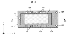
- FIG. 2 is a top view of the temperature control unit 10 in the first embodiment
- FIG. 3 is a side view.
- FIG. 4 shows a cross section taken along the line AA of FIG. 3
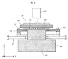
- FIG. 5 shows a cross section taken along the line BB of FIG.
- the temperature control unit 10 of the first embodiment has a Peltier element 103 for heating and cooling the sample 7 to be measured.
- a temperature control member 101 is attached to one surface (temperature control surface side) of the Peltier element 103, and the sample 7 is fixed to the upper surface of the Peltier element 103 in close contact with the sample 7.
- the temperature control member 101 has a built-in thermistor 106 in order to measure its own temperature.
- thermistor 106 By measuring the temperature of the temperature control member 101 with the thermistor 106 and controlling the temperature of the Peltier element 103 with a current adjusting means (not shown), it is possible to apply a predetermined temperature to the sample 7.
- the heat conductive member 104 is attached so as to come into contact with the lower surface (heat dissipation surface) side of the Peltier element 103. Further, a heat sink 105 is attached to the end of the heat conductive member 104. The heat sink 105 is cooled by a cooling means (not shown).
- the temperature control unit 10 is provided with a support member 102 that supports the temperature control member 101, the Peltier element 103, and the heat conduction member 104, and adjusts the distance between the image pickup means 2A and the sample 7.
- the support member 102 fixes and supports the Peltier element 103 and the temperature control member 101 with the mounting screws 108.
- the temperature control unit 10 is arranged so as to face the image pickup means 2A of the optical measurement unit 2. Further, the temperature control unit 10 is formed by sequentially arranging the sample 7, the temperature control member 101, the Peltier element 103, the support member 102, the heat conduction member 104, and the heat sink 105 from the upper part to the lower part.
- FIG. 2 specifically illustrates the support structure between the support member 102 and the temperature control member 101
- FIG. 4 specifically illustrates the support structure between the support member 102 and the heat conductive member 104.
- the support member 102 is attached at three places so as to be fixed to the table 6F by the adjusting screw 107.
- the surface angle of the support member 102 can be changed by adjusting the mounting heights of the three screws. Then, when the table 6F is moved in the X and Y directions in the drawing during imaging, the measurement position of the sample 7 and the distance D of the imaging means 2A can be adjusted so as to be within a range in which no focus shift occurs. ing.
- This structure includes an optical measurement unit 2 for optically observing the sample 7, a temperature control unit 10 mounted on the table 6F by a support member 102 for heating and cooling for the fluorescent labeling reaction of the sample 7, and the sample 7. It is an imaging mechanism provided with a moving mechanism for moving the table 6F in order to photograph the entire area of the Peltier element 103, and the temperature control unit 10 is brought into contact with one surface of the Peltier element 103 to control the temperature for heating and cooling the sample 7. A portion 101, a heat conductive member 104 abutting on the other surface of the Peltier element 103, and a support member 102 connected to the temperature control portion 101 are provided, and at least the heat conductive member 104 is connected to the cooling means (heat sink 105). Has been done.
- the heat conductive member 104 is made of a material having a higher thermal conductivity than the support member 102. Further, the support member 102 uses a material having a coefficient of linear expansion lower than that of the heat conductive member 104.
- the support member 102 is provided with an iron-based alloy, for example, a Fe—Ni 36% alloy (thermal conductivity 13 [Wm -1 K -1 ], coefficient of linear expansion 1.7 ⁇ 10 -6 [K -1 ]).
- Al alloy A6063 thermal conductivity 220 [Wm -1 K -1 ], coefficient of linear expansion 23 ⁇ 10 -6 [K -1 ]) is used as the heat conductive member.
- the heat conductive member 104 is fixed to the support member 102 by the fixing screw 109 at two central locations in the lateral direction (Y direction in the figure). By being fixed at the central portion, the deformation of the heat conductive member 104 in the longitudinal direction (X direction in the drawing) is not hindered by the fixing screw 109, and the thermal stress on the support member 102 does not act.
- the support member 102 has a through hole larger than the outer shape of the heat conductive member 104 in the central portion so as not to come into contact with the heat conductive member 104.
- the heat conductive member 104 has a surface that partially contacts in the direction of gravity (Z direction in the figure) so that its own weight is supported, but the area of the heat conductive member 104 is such that the heat conductive member 104 is in contact with the Peltier element 103. It is sufficiently small compared to the area of the surface.
- the support member 102 has a groove-shaped portion, the heat conductive member 104 is arranged in the groove-shaped portion, and a gap is provided between the support member 102 and the heat conductive member 104 in the X direction in the drawing. Therefore, the thermal deformation of the heat conductive member 104 is not transmitted to the support member 102.
- the temperature control unit 10 applies a two-step temperature to the sample 7.
- One is a temperature for promoting the fluorescent labeling reaction in the sample 7, and here, the temperature is T1.
- the other is the temperature at which the temperature control member 101 is kept constant during imaging (hereinafter referred to as the imaging temperature) in order to suppress thermal deformation of the temperature control device 10, and this temperature is defined as T2.
- the temperature control member 102 is heated to a temperature T1 in order to promote the fluorescent labeling reaction by the reagent injected into the sample 7. Then, after the time required for the reaction has elapsed, the temperature control member 101 is lowered to the imaging temperature T2, and then imaging is performed.
- the temperature of the temperature control member 101 attached to the temperature control surface side of the Peltier element 103 becomes constant due to the temperature control of the Peltier element 103.
- the temperature control member 101 When the temperature control member 101 is cooled to the imaging temperature T2, the temperature on the heat dissipation surface side of the Peltier element 103 rises. The heat generated here is transferred to the heat sink 105 via the heat conductive member 104. Then, the heat sink 105 is cooled by a cooling means (for example, a fan) (not shown).
- a cooling means for example, a fan
- the support member 102 is in contact with the heat conductive member 104.
- the heat conductive member 104 is made of a material having a higher thermal conductivity than the support member 102, most of the heat generated by the Peltier element 103 propagates to the heat transfer unit 104. It will be.
- the amount of heat transferred to the support member 102 is reduced, and the temperature change can be reduced, thereby reducing the amount of heat deformation.
- the support member 102 uses an iron-based alloy having a low coefficient of linear expansion, for example, a Fe—Ni 36% alloy (coefficient of linear expansion 1.7 ⁇ 10-6 [K -1 ]).
- the amount of thermal deformation is smaller than that of the conventional configuration.
- FIG. 6, which is described for reference in comparison with the present invention, shows the appearance of the conventional temperature control device 90. Similar to the configuration of the present invention, the conventional temperature control device 90 is attached with a Peltier element 903, a temperature control member 901, and a support member 902 for heating and cooling the sample 7. A heat conductive member 904 and a heat sink 905 are attached to the bottom surface of the support member 902.
- the sample analyzer 1 having the temperature control mechanism 10 according to the first embodiment described above when the temperature control portion is cooled, most of the heat generated on the heat dissipation side of the Peltier element is propagated by the heat dissipation member. , The temperature change of the support portion can be reduced, and the amount of thermal deformation can be reduced.
- FIG. 7 is a top view of the temperature control unit 10 according to the second embodiment of the present invention
- FIG. 8 is a side view of the temperature control unit 10 according to the second embodiment.
- FIG. 9 shows a cross section of BB in FIG. 7.
- the temperature control unit 10 in this embodiment has a Peltier element 103 for heating and cooling the sample 7 to be measured.
- the sample 7 is mounted in contact with the temperature control member 101 attached to one surface of the Peltier element 103.
- the thermistor 106 for measuring the temperature is attached to the temperature control member 101.
- the temperature of the temperature control member 101 is measured by the thermistor 106.
- the temperature control member 101 can be changed to a predetermined temperature, and the sample 7 can be heated and cooled once.
- the temperature control member 101 is attached to the indicator member 102 by an adjusting screw 107.
- the adjusting screw 107 is provided at three places with respect to the temperature control member 101. By changing the mounting height of this screw, it is possible to adjust the surface of the sample 7 so that the distance to the optical observation system 2A is constant so that it is within the measurement range when the stage is moved. It has become.
- the heat conductive member 104 is provided at a position where it directly contacts the Peltier element 103, and the Peltier element 103 is sandwiched and fixed by the temperature control member 101 and the heat conductive member 104 by tightening the mounting screw 108. ..
- the support member 102 has a hole in the center, and the heat conductive member 104 is attached so as to penetrate through the hole.
- the heat generated by the Peltier element is transferred to the heat sink 105 via the heat conductive member 104.
- the heat sink 105 is cooled by a cooling means (for example, a fan) (not shown). There is a gap between the heat conductive member 104 and the support member 102, and the thermal deformation of the heat conductive member 104 is not transmitted to the support member 102.
- the heat conductive member 104 is made of a material having a higher thermal conductivity than the support member 102. Further, the support member 102 uses a material having a coefficient of linear expansion lower than that of the heat conductive member 104.
- the support member 102 is provided with an iron-based alloy, for example, a Fe—Ni 36% alloy (thermal conductivity 13 [Wm -1 K -1 ], coefficient of linear expansion 1.7 ⁇ 10 -6 [K -1 ]).
- Al alloy A6063 thermal conductivity 210 [Wm -1 K -1 ], coefficient of linear expansion 23 ⁇ 10 -6 [K -1 ]) is used as the heat conductive member.
- the support member 102 is fixed to the table 6F by a screw (not shown).
- the temperature control member 101 When the temperature control member 101 is cooled, the temperature on the heat radiating surface side of the Peltier element 103 rises. The heat generated here is transferred to the heat sink 105 via the heat conductive member 104. Then, the heat sink 105 is cooled by a cooling means (for example, a fan) (not shown).
- a cooling means for example, a fan
- the support member 102 since the support member 102 is not in contact with the heat conductive member 104, all the heat generated on the heat radiating surface of the Peltier element 103 is propagated to the heat transfer unit 104 and not to the support member 102. Therefore, the amount of heat transferred to the support member 102 is reduced, and the temperature change thereof can be reduced, whereby the amount of heat deformation is reduced.
- Example 3 relates to increasing the rigidity of the support member.
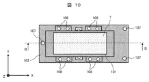
- FIG. 10 is a top view of the temperature control unit 10 in the third embodiment
- FIG. 11 is a side view.
- FIG. 12 shows a cross section taken along the line AA in FIG. 11
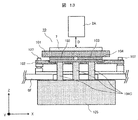
- FIG. 13 shows a cross section taken along the line BB in FIG.
- the temperature control unit 10 in Example 3 has a Peltier element 103 for heating and cooling the sample 7 to be measured.
- a temperature control member 101 is attached to one surface (temperature control surface side) of the Peltier element 103, and the sample 7 is fixed to the upper surface of the Peltier element 103 in close contact with the sample 7.
- the temperature control member 101 has a built-in thermistor 106 in order to measure its own temperature.
- thermistor 106 By measuring the temperature of the temperature control member 101 with the thermistor 106 and controlling the temperature of the Peltier element 103 with a current adjusting means (not shown), it is possible to apply a predetermined temperature to the sample 7.
- the heat conductive member 104 is attached so as to come into contact with the lower surface (heat dissipation surface) side of the Peltier element 103. Further, the heat conductive member 104 has a plurality of transmission paths 104C, and a heat sink 105 is attached to the end portion thereof. The heat sink 105 is cooled by a cooling means (not shown).
- the temperature control unit 10 includes a support member 102 that supports the temperature control member 101, the Peltier element 103, and the heat conduction member 104, and adjusts the distance between the image pickup means 2A and the sample 7.
- the support member 102 fixes and supports the Peltier element 103 and the temperature control member 101 with the mounting screws 108.
- the support member 102 is attached at three places so as to be fixed to the table 6F by the adjusting screw 107.
- the surface angle of the support member 102 can be changed by adjusting the mounting heights of the three screws. Then, when the table 6F is moved in the X and Y directions in the drawing during imaging, the measurement position of the sample 7 and the distance D of the imaging means 2A can be adjusted so as to be within a range in which no focus shift occurs. ing.
- the heat conductive member 104 is made of a material having a higher thermal conductivity than the support member 102. Further, the support member 102 uses a material having a coefficient of linear expansion lower than that of the heat conductive member 104.
- the support member 102 is provided with an iron-based alloy, for example, a Fe—Ni 36% alloy (thermal conductivity 13 [Wm -1 K -1 ], coefficient of linear expansion 1.7 ⁇ 10 -6 [K -1 ]).
- Al alloy A6063 thermal conductivity 210 [Wm -1 K -1 ], coefficient of linear expansion 23 ⁇ 10 -6 [K -1 ]) is used as the heat conductive member.
- Example 3 The effect of Example 3 is the same as that of Example 1, and the difference is that a plurality of heat conductive members 104C are provided on the heat dissipation side of the Peltier element 103. A heat sink 105 is attached to the end of the plurality of heat conductive members 104C.
- the size of each through hole of the support member 102 can be reduced, and the rigidity of the support member 102 can be maintained. ..
- 1 Imaging mechanism
- 2 Optical measuring unit
- 2A Imaging means
- 3 Base frame
- 4 Vibration isolation unit
- 5 X moving mechanism
- 6 Y moving mechanism
- 7 Sample
- 10 Temperature control unit
- 90 Conventional temperature control unit
- 101 Temperature control member
- 102 Support member
- 103 Peltier element
- 104 Heat conduction member
- 105 Heat sink
- 106 Thermistor
- 107 Adjustment screw
- 108 Mounting screw
- 109 Fixed screw
Landscapes
- Physics & Mathematics (AREA)
- Chemical & Material Sciences (AREA)
- Analytical Chemistry (AREA)
- General Physics & Mathematics (AREA)
- Optics & Photonics (AREA)
- Health & Medical Sciences (AREA)
- Engineering & Computer Science (AREA)
- Multimedia (AREA)
- Nuclear Medicine, Radiotherapy & Molecular Imaging (AREA)
- Life Sciences & Earth Sciences (AREA)
- Biochemistry (AREA)
- General Health & Medical Sciences (AREA)
- Immunology (AREA)
- Pathology (AREA)
- Investigating, Analyzing Materials By Fluorescence Or Luminescence (AREA)
- Microscoopes, Condenser (AREA)
- Sampling And Sample Adjustment (AREA)
- Investigating Or Analyzing Materials Using Thermal Means (AREA)
Priority Applications (5)
| Application Number | Priority Date | Filing Date | Title |
|---|---|---|---|
| JP2021532634A JP7161622B2 (ja) | 2019-07-18 | 2019-07-18 | 撮像機構並びに撮像機構を備えた試料分析装置 |
| EP19937365.5A EP4001990A4 (en) | 2019-07-18 | 2019-07-18 | IMAGE CAPTURE MECHANISM AND SAMPLE ANALYZER WITH IMAGE CAPTURE MECHANISM |
| PCT/JP2019/028208 WO2021009892A1 (ja) | 2019-07-18 | 2019-07-18 | 撮像機構並びに撮像機構を備えた試料分析装置 |
| US17/619,624 US12174360B2 (en) | 2019-07-18 | 2019-07-18 | Imaging mechanism and sample analyzing apparatus provided with the same |
| CN201980097911.1A CN114026482B (zh) | 2019-07-18 | 2019-07-18 | 摄像机构以及具有摄像机构的试样分析装置 |
Applications Claiming Priority (1)
| Application Number | Priority Date | Filing Date | Title |
|---|---|---|---|
| PCT/JP2019/028208 WO2021009892A1 (ja) | 2019-07-18 | 2019-07-18 | 撮像機構並びに撮像機構を備えた試料分析装置 |
Publications (1)
| Publication Number | Publication Date |
|---|---|
| WO2021009892A1 true WO2021009892A1 (ja) | 2021-01-21 |
Family
ID=74210315
Family Applications (1)
| Application Number | Title | Priority Date | Filing Date |
|---|---|---|---|
| PCT/JP2019/028208 Ceased WO2021009892A1 (ja) | 2019-07-18 | 2019-07-18 | 撮像機構並びに撮像機構を備えた試料分析装置 |
Country Status (5)
| Country | Link |
|---|---|
| US (1) | US12174360B2 (https=) |
| EP (1) | EP4001990A4 (https=) |
| JP (1) | JP7161622B2 (https=) |
| CN (1) | CN114026482B (https=) |
| WO (1) | WO2021009892A1 (https=) |
Cited By (2)
| Publication number | Priority date | Publication date | Assignee | Title |
|---|---|---|---|---|
| RU2775642C1 (ru) * | 2021-07-19 | 2022-07-05 | Федеральное государственное бюджетное учреждение науки Сибирский федеральный научный центр агробиотехнологий Российской академии наук (СФНЦА РАН) | Устройство для формирования температурного профиля |
| US20240251166A1 (en) * | 2023-01-24 | 2024-07-25 | Canon Kabushiki Kaisha | Image stabilizing mechanism and image capturing apparatus |
Families Citing this family (2)
| Publication number | Priority date | Publication date | Assignee | Title |
|---|---|---|---|---|
| CN115373878B (zh) * | 2022-10-27 | 2023-03-28 | 麒麟软件有限公司 | 基于x框架的防截屏扩展协议实现系统 |
| EP4613840A1 (en) | 2024-03-05 | 2025-09-10 | Max-Planck-Gesellschaft zur Förderung der Wissenschaften e.V. | Microscope temperature stage |
Citations (5)
| Publication number | Priority date | Publication date | Assignee | Title |
|---|---|---|---|---|
| US7081600B2 (en) | 2002-10-02 | 2006-07-25 | Stragene California | Method and apparatus for cover assembly for thermal cycling of samples |
| JP2011234681A (ja) * | 2010-05-12 | 2011-11-24 | Hitachi High-Technologies Corp | 核酸配列解析装置に用いられる温度制御装置 |
| JP2015090458A (ja) * | 2013-11-07 | 2015-05-11 | 株式会社日立ハイテクノロジーズ | 分析装置 |
| US20150308931A1 (en) * | 2012-12-03 | 2015-10-29 | Leica Biosystems Melbourne Pty Ltd | Thermal module for a sample processing assembly |
| JP2017183533A (ja) * | 2016-03-30 | 2017-10-05 | 株式会社Uacj | 回路基板付きヒートシンク及びその製造方法 |
Family Cites Families (7)
| Publication number | Priority date | Publication date | Assignee | Title |
|---|---|---|---|---|
| FR2628215A1 (fr) * | 1988-03-02 | 1989-09-08 | Helena Lab Corp | Procede et appareil automatique d'electrophorese |
| CN2444231Y (zh) * | 2000-11-20 | 2001-08-22 | 中国科学院物理研究所 | 一种显微镜样品观测台 |
| JP4547176B2 (ja) * | 2004-03-29 | 2010-09-22 | 大学共同利用機関法人情報・システム研究機構 | 試料温度調節装置 |
| JP2006090749A (ja) | 2004-09-21 | 2006-04-06 | Olympus Corp | 温度調整装置 |
| JP4868203B2 (ja) * | 2004-10-27 | 2012-02-01 | オリンパス株式会社 | 培養標本観察装置 |
| DE102011052738A1 (de) * | 2011-08-16 | 2013-02-21 | Leica Microsystems Cms Gmbh | Detektorvorrichtung |
| JP6508140B2 (ja) * | 2016-06-30 | 2019-05-08 | 東亜ディーケーケー株式会社 | 光電子増倍管、測定装置、製造用治具 |
-
2019
- 2019-07-18 US US17/619,624 patent/US12174360B2/en active Active
- 2019-07-18 WO PCT/JP2019/028208 patent/WO2021009892A1/ja not_active Ceased
- 2019-07-18 EP EP19937365.5A patent/EP4001990A4/en active Pending
- 2019-07-18 JP JP2021532634A patent/JP7161622B2/ja active Active
- 2019-07-18 CN CN201980097911.1A patent/CN114026482B/zh active Active
Patent Citations (5)
| Publication number | Priority date | Publication date | Assignee | Title |
|---|---|---|---|---|
| US7081600B2 (en) | 2002-10-02 | 2006-07-25 | Stragene California | Method and apparatus for cover assembly for thermal cycling of samples |
| JP2011234681A (ja) * | 2010-05-12 | 2011-11-24 | Hitachi High-Technologies Corp | 核酸配列解析装置に用いられる温度制御装置 |
| US20150308931A1 (en) * | 2012-12-03 | 2015-10-29 | Leica Biosystems Melbourne Pty Ltd | Thermal module for a sample processing assembly |
| JP2015090458A (ja) * | 2013-11-07 | 2015-05-11 | 株式会社日立ハイテクノロジーズ | 分析装置 |
| JP2017183533A (ja) * | 2016-03-30 | 2017-10-05 | 株式会社Uacj | 回路基板付きヒートシンク及びその製造方法 |
Cited By (3)
| Publication number | Priority date | Publication date | Assignee | Title |
|---|---|---|---|---|
| RU2775642C1 (ru) * | 2021-07-19 | 2022-07-05 | Федеральное государственное бюджетное учреждение науки Сибирский федеральный научный центр агробиотехнологий Российской академии наук (СФНЦА РАН) | Устройство для формирования температурного профиля |
| US20240251166A1 (en) * | 2023-01-24 | 2024-07-25 | Canon Kabushiki Kaisha | Image stabilizing mechanism and image capturing apparatus |
| US12425735B2 (en) * | 2023-01-24 | 2025-09-23 | Canon Kabushiki Kaisha | Image stabilizing mechanism and image capturing apparatus |
Also Published As
| Publication number | Publication date |
|---|---|
| EP4001990A1 (en) | 2022-05-25 |
| US12174360B2 (en) | 2024-12-24 |
| CN114026482A (zh) | 2022-02-08 |
| CN114026482B (zh) | 2023-11-14 |
| JPWO2021009892A1 (https=) | 2021-01-21 |
| JP7161622B2 (ja) | 2022-10-26 |
| US20220350124A1 (en) | 2022-11-03 |
| EP4001990A4 (en) | 2023-04-19 |
Similar Documents
| Publication | Publication Date | Title |
|---|---|---|
| JP4825812B2 (ja) | 温度を調整可能なチャック装置を用いた半導体ウエハ検査方法および装置 | |
| JP4659328B2 (ja) | 被検査体を温度制御するプローブ装置 | |
| JP5254874B2 (ja) | 改良された冷却器/加熱器の構成 | |
| US8853648B2 (en) | Sample holder, method for use of the sample holder, and charged particle device | |
| JP7161622B2 (ja) | 撮像機構並びに撮像機構を備えた試料分析装置 | |
| US8082977B2 (en) | Ceramic mounting for wafer apparatus with thermal expansion feature | |
| TWI406102B (zh) | 機台裝置,曝光裝置及微裝置製造方法 | |
| US11782022B2 (en) | Capillary electrophoresis apparatus and thermostat | |
| CN121245183A (zh) | 用于激光加工系统的设备、具有该设备的激光加工系统及用于调节光学元件的焦点位置的方法 | |
| JP2009300122A (ja) | エージング装置 | |
| CN110066859A (zh) | 数字pcr检测仪 | |
| CN103087905B (zh) | 一种测序反应台及核酸序列检测设备 | |
| JP2017016810A (ja) | 荷電粒子線装置、および試料ホルダの温度制御方法 | |
| JP5246995B2 (ja) | 集束荷電粒子ビーム装置 | |
| JP5395520B2 (ja) | 微細構造転写装置 | |
| CN115318348B (zh) | 温度控制装置及微流控检测系统 | |
| JP6890195B2 (ja) | キャピラリ電気泳動装置および恒温槽 | |
| JP4547176B2 (ja) | 試料温度調節装置 | |
| JP4959669B2 (ja) | プローブ装置 | |
| CN223486048U (zh) | 具有散热组件的探针台 | |
| JP4889665B2 (ja) | 基板支持装置、基板測定装置、熱伝導シート取り付け具及び熱伝導シート取り付け方法 | |
| JP5701330B2 (ja) | 核酸配列解析装置に用いられる温度制御装置 | |
| JP2012145283A (ja) | 加熱装置 | |
| JP2025114055A (ja) | 電子顕微鏡の冷却試料ホルダ及びこれを用いた荷電粒子線装置 | |
| JP2006343278A (ja) | 恒温槽装置 |
Legal Events
| Date | Code | Title | Description |
|---|---|---|---|
| 121 | Ep: the epo has been informed by wipo that ep was designated in this application |
Ref document number: 19937365 Country of ref document: EP Kind code of ref document: A1 |
|
| ENP | Entry into the national phase |
Ref document number: 2021532634 Country of ref document: JP Kind code of ref document: A |
|
| NENP | Non-entry into the national phase |
Ref country code: DE |
|
| ENP | Entry into the national phase |
Ref document number: 2019937365 Country of ref document: EP Effective date: 20220218 |