WO2021006242A1 - 細胞培養足場、その製造方法と足場製造キット及び細胞培養物の作製方法 - Google Patents
細胞培養足場、その製造方法と足場製造キット及び細胞培養物の作製方法 Download PDFInfo
- Publication number
- WO2021006242A1 WO2021006242A1 PCT/JP2020/026399 JP2020026399W WO2021006242A1 WO 2021006242 A1 WO2021006242 A1 WO 2021006242A1 JP 2020026399 W JP2020026399 W JP 2020026399W WO 2021006242 A1 WO2021006242 A1 WO 2021006242A1
- Authority
- WO
- WIPO (PCT)
- Prior art keywords
- cell
- cell culture
- cells
- cell adhesion
- base material
- Prior art date
Links
- 239000003795 chemical substances by application Substances 0.000 title description 3
- 239000000835 fiber Substances 0.000 title 1
- 238000004113 cell culture Methods 0.000 claims abstract description 98
- 108010067225 Cell Adhesion Molecules Proteins 0.000 claims abstract description 85
- 239000005871 repellent Substances 0.000 claims abstract description 26
- 238000004519 manufacturing process Methods 0.000 claims abstract description 13
- 238000012258 culturing Methods 0.000 claims abstract description 12
- 102000008395 cell adhesion mediator activity proteins Human genes 0.000 claims abstract 7
- 210000004027 cell Anatomy 0.000 claims description 160
- 102000016289 Cell Adhesion Molecules Human genes 0.000 claims description 78
- 239000000463 material Substances 0.000 claims description 70
- 238000000034 method Methods 0.000 claims description 60
- 239000003566 sealing material Substances 0.000 claims description 46
- 239000000758 substrate Substances 0.000 claims description 20
- 230000015572 biosynthetic process Effects 0.000 claims description 13
- 239000011148 porous material Substances 0.000 claims description 8
- 239000000853 adhesive Substances 0.000 claims description 5
- 230000001070 adhesive effect Effects 0.000 claims description 5
- 102000010834 Extracellular Matrix Proteins Human genes 0.000 claims description 4
- 108010037362 Extracellular Matrix Proteins Proteins 0.000 claims description 4
- 210000002744 extracellular matrix Anatomy 0.000 claims description 4
- 230000008569 process Effects 0.000 claims description 2
- 239000002609 medium Substances 0.000 description 49
- 239000000243 solution Substances 0.000 description 48
- 239000006144 Dulbecco’s modified Eagle's medium Substances 0.000 description 28
- 239000012091 fetal bovine serum Substances 0.000 description 18
- NWIBSHFKIJFRCO-WUDYKRTCSA-N Mytomycin Chemical compound C1N2C(C(C(C)=C(N)C3=O)=O)=C3[C@@H](COC(N)=O)[C@@]2(OC)[C@@H]2[C@H]1N2 NWIBSHFKIJFRCO-WUDYKRTCSA-N 0.000 description 14
- IAZDPXIOMUYVGZ-UHFFFAOYSA-N Dimethylsulphoxide Chemical compound CS(C)=O IAZDPXIOMUYVGZ-UHFFFAOYSA-N 0.000 description 11
- 238000004299 exfoliation Methods 0.000 description 11
- 108010007093 dispase Proteins 0.000 description 10
- 238000007789 sealing Methods 0.000 description 10
- 238000012546 transfer Methods 0.000 description 10
- DNIAPMSPPWPWGF-UHFFFAOYSA-N Propylene glycol Chemical compound CC(O)CO DNIAPMSPPWPWGF-UHFFFAOYSA-N 0.000 description 9
- IJGRMHOSHXDMSA-UHFFFAOYSA-N Atomic nitrogen Chemical compound N#N IJGRMHOSHXDMSA-UHFFFAOYSA-N 0.000 description 8
- 210000004748 cultured cell Anatomy 0.000 description 8
- 108010010803 Gelatin Proteins 0.000 description 7
- 239000006285 cell suspension Substances 0.000 description 7
- 238000010586 diagram Methods 0.000 description 7
- 229920000159 gelatin Polymers 0.000 description 7
- 239000008273 gelatin Substances 0.000 description 7
- 235000019322 gelatine Nutrition 0.000 description 7
- 235000011852 gelatine desserts Nutrition 0.000 description 7
- 229960004857 mitomycin Drugs 0.000 description 7
- 239000000203 mixture Substances 0.000 description 7
- 239000006228 supernatant Substances 0.000 description 7
- 238000010257 thawing Methods 0.000 description 7
- 229910021642 ultra pure water Inorganic materials 0.000 description 7
- 239000012498 ultrapure water Substances 0.000 description 7
- DLFVBJFMPXGRIB-UHFFFAOYSA-N Acetamide Chemical compound CC(N)=O DLFVBJFMPXGRIB-UHFFFAOYSA-N 0.000 description 6
- KCXVZYZYPLLWCC-UHFFFAOYSA-N EDTA Chemical compound OC(=O)CN(CC(O)=O)CCN(CC(O)=O)CC(O)=O KCXVZYZYPLLWCC-UHFFFAOYSA-N 0.000 description 6
- LYCAIKOWRPUZTN-UHFFFAOYSA-N Ethylene glycol Chemical compound OCCO LYCAIKOWRPUZTN-UHFFFAOYSA-N 0.000 description 6
- 102000004142 Trypsin Human genes 0.000 description 6
- 108090000631 Trypsin Proteins 0.000 description 6
- 239000003814 drug Substances 0.000 description 6
- -1 polytetrafluoroethylene Polymers 0.000 description 6
- 230000007261 regionalization Effects 0.000 description 6
- 239000012588 trypsin Substances 0.000 description 6
- XLYOFNOQVPJJNP-UHFFFAOYSA-N water Substances O XLYOFNOQVPJJNP-UHFFFAOYSA-N 0.000 description 6
- DGVVWUTYPXICAM-UHFFFAOYSA-N β‐Mercaptoethanol Chemical compound OCCS DGVVWUTYPXICAM-UHFFFAOYSA-N 0.000 description 6
- 108010067306 Fibronectins Proteins 0.000 description 5
- 102000016359 Fibronectins Human genes 0.000 description 5
- 239000011248 coating agent Substances 0.000 description 5
- 238000000576 coating method Methods 0.000 description 5
- 238000005138 cryopreservation Methods 0.000 description 5
- 229940079593 drug Drugs 0.000 description 5
- 108010082117 matrigel Proteins 0.000 description 5
- 238000002360 preparation method Methods 0.000 description 5
- 229920005989 resin Polymers 0.000 description 5
- 239000011347 resin Substances 0.000 description 5
- 210000000130 stem cell Anatomy 0.000 description 5
- LFQSCWFLJHTTHZ-UHFFFAOYSA-N Ethanol Chemical compound CCO LFQSCWFLJHTTHZ-UHFFFAOYSA-N 0.000 description 4
- ZDXPYRJPNDTMRX-VKHMYHEASA-N L-glutamine Chemical compound OC(=O)[C@@H](N)CCC(N)=O ZDXPYRJPNDTMRX-VKHMYHEASA-N 0.000 description 4
- 229930182816 L-glutamine Natural products 0.000 description 4
- 108010031318 Vitronectin Proteins 0.000 description 4
- 102100035140 Vitronectin Human genes 0.000 description 4
- 230000032683 aging Effects 0.000 description 4
- 239000004205 dimethyl polysiloxane Substances 0.000 description 4
- 238000002474 experimental method Methods 0.000 description 4
- 238000001914 filtration Methods 0.000 description 4
- 239000007788 liquid Substances 0.000 description 4
- 239000011259 mixed solution Substances 0.000 description 4
- 229910052757 nitrogen Inorganic materials 0.000 description 4
- 238000010899 nucleation Methods 0.000 description 4
- 229920000435 poly(dimethylsiloxane) Polymers 0.000 description 4
- 238000004528 spin coating Methods 0.000 description 4
- 229920000208 temperature-responsive polymer Polymers 0.000 description 4
- 102100024785 Fibroblast growth factor 2 Human genes 0.000 description 3
- 108090000379 Fibroblast growth factor 2 Proteins 0.000 description 3
- 239000003153 chemical reaction reagent Substances 0.000 description 3
- 229920001577 copolymer Polymers 0.000 description 3
- 238000004090 dissolution Methods 0.000 description 3
- 239000003797 essential amino acid Substances 0.000 description 3
- 238000007710 freezing Methods 0.000 description 3
- 230000008014 freezing Effects 0.000 description 3
- 229920001343 polytetrafluoroethylene Polymers 0.000 description 3
- 239000004810 polytetrafluoroethylene Substances 0.000 description 3
- 239000000843 powder Substances 0.000 description 3
- 238000005507 spraying Methods 0.000 description 3
- 230000001954 sterilising effect Effects 0.000 description 3
- 238000004659 sterilization and disinfection Methods 0.000 description 3
- 210000001519 tissue Anatomy 0.000 description 3
- UMCMPZBLKLEWAF-BCTGSCMUSA-N 3-[(3-cholamidopropyl)dimethylammonio]propane-1-sulfonate Chemical compound C([C@H]1C[C@H]2O)[C@H](O)CC[C@]1(C)[C@@H]1[C@@H]2[C@@H]2CC[C@H]([C@@H](CCC(=O)NCCC[N+](C)(C)CCCS([O-])(=O)=O)C)[C@@]2(C)[C@@H](O)C1 UMCMPZBLKLEWAF-BCTGSCMUSA-N 0.000 description 2
- HJCMDXDYPOUFDY-WHFBIAKZSA-N Ala-Gln Chemical compound C[C@H](N)C(=O)N[C@H](C(O)=O)CCC(N)=O HJCMDXDYPOUFDY-WHFBIAKZSA-N 0.000 description 2
- 108091003079 Bovine Serum Albumin Proteins 0.000 description 2
- 108010035532 Collagen Proteins 0.000 description 2
- 102000008186 Collagen Human genes 0.000 description 2
- VGGSQFUCUMXWEO-UHFFFAOYSA-N Ethene Chemical compound C=C VGGSQFUCUMXWEO-UHFFFAOYSA-N 0.000 description 2
- 239000005977 Ethylene Substances 0.000 description 2
- XUIMIQQOPSSXEZ-UHFFFAOYSA-N Silicon Chemical compound [Si] XUIMIQQOPSSXEZ-UHFFFAOYSA-N 0.000 description 2
- 229960002648 alanylglutamine Drugs 0.000 description 2
- 230000008901 benefit Effects 0.000 description 2
- 230000021164 cell adhesion Effects 0.000 description 2
- 230000008859 change Effects 0.000 description 2
- 229920001436 collagen Polymers 0.000 description 2
- 230000009089 cytolysis Effects 0.000 description 2
- 238000003618 dip coating Methods 0.000 description 2
- 230000000694 effects Effects 0.000 description 2
- 229920001971 elastomer Polymers 0.000 description 2
- 235000020776 essential amino acid Nutrition 0.000 description 2
- 230000003203 everyday effect Effects 0.000 description 2
- 238000009472 formulation Methods 0.000 description 2
- 239000001963 growth medium Substances 0.000 description 2
- 238000010438 heat treatment Methods 0.000 description 2
- 230000002209 hydrophobic effect Effects 0.000 description 2
- 230000001939 inductive effect Effects 0.000 description 2
- 108090000765 processed proteins & peptides Proteins 0.000 description 2
- 230000035755 proliferation Effects 0.000 description 2
- 239000010453 quartz Substances 0.000 description 2
- 229910052710 silicon Inorganic materials 0.000 description 2
- 239000010703 silicon Substances 0.000 description 2
- VYPSYNLAJGMNEJ-UHFFFAOYSA-N silicon dioxide Inorganic materials O=[Si]=O VYPSYNLAJGMNEJ-UHFFFAOYSA-N 0.000 description 2
- 238000013518 transcription Methods 0.000 description 2
- 230000035897 transcription Effects 0.000 description 2
- 238000012795 verification Methods 0.000 description 2
- 241000283690 Bos taurus Species 0.000 description 1
- 102000004266 Collagen Type IV Human genes 0.000 description 1
- 108010042086 Collagen Type IV Proteins 0.000 description 1
- 206010011906 Death Diseases 0.000 description 1
- 108010014258 Elastin Proteins 0.000 description 1
- 102000016942 Elastin Human genes 0.000 description 1
- 108090000790 Enzymes Proteins 0.000 description 1
- 102000004190 Enzymes Human genes 0.000 description 1
- PYVHTIWHNXTVPF-UHFFFAOYSA-N F.F.F.F.C=C Chemical compound F.F.F.F.C=C PYVHTIWHNXTVPF-UHFFFAOYSA-N 0.000 description 1
- 108050007372 Fibroblast Growth Factor Proteins 0.000 description 1
- 102000018233 Fibroblast Growth Factor Human genes 0.000 description 1
- 229920002971 Heparan sulfate Polymers 0.000 description 1
- 108010085895 Laminin Proteins 0.000 description 1
- 102000007547 Laminin Human genes 0.000 description 1
- 239000002033 PVDF binder Substances 0.000 description 1
- 229920002518 Polyallylamine hydrochloride Polymers 0.000 description 1
- 229920002873 Polyethylenimine Polymers 0.000 description 1
- 108010039918 Polylysine Proteins 0.000 description 1
- 239000004793 Polystyrene Substances 0.000 description 1
- 108010067787 Proteoglycans Proteins 0.000 description 1
- 239000002253 acid Substances 0.000 description 1
- 229910052586 apatite Inorganic materials 0.000 description 1
- 210000002469 basement membrane Anatomy 0.000 description 1
- 229940098773 bovine serum albumin Drugs 0.000 description 1
- 150000001768 cations Chemical class 0.000 description 1
- 230000004956 cell adhesive effect Effects 0.000 description 1
- 230000003833 cell viability Effects 0.000 description 1
- 210000002236 cellular spheroid Anatomy 0.000 description 1
- 239000004927 clay Substances 0.000 description 1
- 239000000470 constituent Substances 0.000 description 1
- 239000000356 contaminant Substances 0.000 description 1
- 238000012136 culture method Methods 0.000 description 1
- 231100000433 cytotoxic Toxicity 0.000 description 1
- 230000001472 cytotoxic effect Effects 0.000 description 1
- 230000002354 daily effect Effects 0.000 description 1
- 230000006866 deterioration Effects 0.000 description 1
- 230000004069 differentiation Effects 0.000 description 1
- 238000007598 dipping method Methods 0.000 description 1
- 229920002549 elastin Polymers 0.000 description 1
- 238000011156 evaluation Methods 0.000 description 1
- 238000000605 extraction Methods 0.000 description 1
- 230000001605 fetal effect Effects 0.000 description 1
- 210000002950 fibroblast Anatomy 0.000 description 1
- 229940126864 fibroblast growth factor Drugs 0.000 description 1
- 238000007667 floating Methods 0.000 description 1
- 239000007789 gas Substances 0.000 description 1
- 239000011521 glass Substances 0.000 description 1
- HCDGVLDPFQMKDK-UHFFFAOYSA-N hexafluoropropylene Chemical compound FC(F)=C(F)C(F)(F)F HCDGVLDPFQMKDK-UHFFFAOYSA-N 0.000 description 1
- 229910052588 hydroxylapatite Inorganic materials 0.000 description 1
- 239000011159 matrix material Substances 0.000 description 1
- 239000006082 mold release agent Substances 0.000 description 1
- 210000000056 organ Anatomy 0.000 description 1
- 210000002220 organoid Anatomy 0.000 description 1
- VSIIXMUUUJUKCM-UHFFFAOYSA-D pentacalcium;fluoride;triphosphate Chemical compound [F-].[Ca+2].[Ca+2].[Ca+2].[Ca+2].[Ca+2].[O-]P([O-])([O-])=O.[O-]P([O-])([O-])=O.[O-]P([O-])([O-])=O VSIIXMUUUJUKCM-UHFFFAOYSA-D 0.000 description 1
- XYJRXVWERLGGKC-UHFFFAOYSA-D pentacalcium;hydroxide;triphosphate Chemical compound [OH-].[Ca+2].[Ca+2].[Ca+2].[Ca+2].[Ca+2].[O-]P([O-])([O-])=O.[O-]P([O-])([O-])=O.[O-]P([O-])([O-])=O XYJRXVWERLGGKC-UHFFFAOYSA-D 0.000 description 1
- 239000004033 plastic Substances 0.000 description 1
- 229920003023 plastic Polymers 0.000 description 1
- 210000001778 pluripotent stem cell Anatomy 0.000 description 1
- 229920002493 poly(chlorotrifluoroethylene) Polymers 0.000 description 1
- 239000005023 polychlorotrifluoroethylene (PCTFE) polymer Substances 0.000 description 1
- 229920000656 polylysine Polymers 0.000 description 1
- 229920000642 polymer Polymers 0.000 description 1
- 229920002223 polystyrene Polymers 0.000 description 1
- 229920002620 polyvinyl fluoride Polymers 0.000 description 1
- 229920002981 polyvinylidene fluoride Polymers 0.000 description 1
- 102000004169 proteins and genes Human genes 0.000 description 1
- 108090000623 proteins and genes Proteins 0.000 description 1
- 238000011084 recovery Methods 0.000 description 1
- 230000001172 regenerating effect Effects 0.000 description 1
- 230000002940 repellent Effects 0.000 description 1
- 238000009751 slip forming Methods 0.000 description 1
- 239000002904 solvent Substances 0.000 description 1
- 230000004936 stimulating effect Effects 0.000 description 1
- 230000000638 stimulation Effects 0.000 description 1
- 239000011550 stock solution Substances 0.000 description 1
- 238000003860 storage Methods 0.000 description 1
- 239000000126 substance Substances 0.000 description 1
- 239000000725 suspension Substances 0.000 description 1
- 229920005992 thermoplastic resin Polymers 0.000 description 1
- 229920001187 thermosetting polymer Polymers 0.000 description 1
Images


Classifications
-
- C—CHEMISTRY; METALLURGY
- C12—BIOCHEMISTRY; BEER; SPIRITS; WINE; VINEGAR; MICROBIOLOGY; ENZYMOLOGY; MUTATION OR GENETIC ENGINEERING
- C12M—APPARATUS FOR ENZYMOLOGY OR MICROBIOLOGY; APPARATUS FOR CULTURING MICROORGANISMS FOR PRODUCING BIOMASS, FOR GROWING CELLS OR FOR OBTAINING FERMENTATION OR METABOLIC PRODUCTS, i.e. BIOREACTORS OR FERMENTERS
- C12M25/00—Means for supporting, enclosing or fixing the microorganisms, e.g. immunocoatings
- C12M25/14—Scaffolds; Matrices
-
- C—CHEMISTRY; METALLURGY
- C12—BIOCHEMISTRY; BEER; SPIRITS; WINE; VINEGAR; MICROBIOLOGY; ENZYMOLOGY; MUTATION OR GENETIC ENGINEERING
- C12M—APPARATUS FOR ENZYMOLOGY OR MICROBIOLOGY; APPARATUS FOR CULTURING MICROORGANISMS FOR PRODUCING BIOMASS, FOR GROWING CELLS OR FOR OBTAINING FERMENTATION OR METABOLIC PRODUCTS, i.e. BIOREACTORS OR FERMENTERS
- C12M23/00—Constructional details, e.g. recesses, hinges
- C12M23/20—Material Coatings
-
- C—CHEMISTRY; METALLURGY
- C12—BIOCHEMISTRY; BEER; SPIRITS; WINE; VINEGAR; MICROBIOLOGY; ENZYMOLOGY; MUTATION OR GENETIC ENGINEERING
- C12N—MICROORGANISMS OR ENZYMES; COMPOSITIONS THEREOF; PROPAGATING, PRESERVING, OR MAINTAINING MICROORGANISMS; MUTATION OR GENETIC ENGINEERING; CULTURE MEDIA
- C12N5/00—Undifferentiated human, animal or plant cells, e.g. cell lines; Tissues; Cultivation or maintenance thereof; Culture media therefor
- C12N5/0062—General methods for three-dimensional culture
-
- C—CHEMISTRY; METALLURGY
- C12—BIOCHEMISTRY; BEER; SPIRITS; WINE; VINEGAR; MICROBIOLOGY; ENZYMOLOGY; MUTATION OR GENETIC ENGINEERING
- C12N—MICROORGANISMS OR ENZYMES; COMPOSITIONS THEREOF; PROPAGATING, PRESERVING, OR MAINTAINING MICROORGANISMS; MUTATION OR GENETIC ENGINEERING; CULTURE MEDIA
- C12N5/00—Undifferentiated human, animal or plant cells, e.g. cell lines; Tissues; Cultivation or maintenance thereof; Culture media therefor
- C12N5/0068—General culture methods using substrates
-
- C—CHEMISTRY; METALLURGY
- C12—BIOCHEMISTRY; BEER; SPIRITS; WINE; VINEGAR; MICROBIOLOGY; ENZYMOLOGY; MUTATION OR GENETIC ENGINEERING
- C12N—MICROORGANISMS OR ENZYMES; COMPOSITIONS THEREOF; PROPAGATING, PRESERVING, OR MAINTAINING MICROORGANISMS; MUTATION OR GENETIC ENGINEERING; CULTURE MEDIA
- C12N2533/00—Supports or coatings for cell culture, characterised by material
- C12N2533/30—Synthetic polymers
-
- C—CHEMISTRY; METALLURGY
- C12—BIOCHEMISTRY; BEER; SPIRITS; WINE; VINEGAR; MICROBIOLOGY; ENZYMOLOGY; MUTATION OR GENETIC ENGINEERING
- C12N—MICROORGANISMS OR ENZYMES; COMPOSITIONS THEREOF; PROPAGATING, PRESERVING, OR MAINTAINING MICROORGANISMS; MUTATION OR GENETIC ENGINEERING; CULTURE MEDIA
- C12N2535/00—Supports or coatings for cell culture characterised by topography
- C12N2535/10—Patterned coating
Definitions
- the present invention relates to a cell culture scaffold for culturing cells and a method for producing a cell culture (particularly a three-dimensional cell aggregate) using the cell culture scaffold.
- Non-Patent Document 1 As a method of exfoliating the cell culture from the culture scaffold after the cell culture, a method using an enzyme is known. However, with this method, it is difficult to recover the cell culture without breaking the bonds between the cells. Further, there is also known a method in which a temperature-responsive polymer is used for a cell culture scaffold and heat treatment is performed to decompose the temperature-responsive polymer to peel off the cell culture from the culture scaffold and recover it (for example, Patent Document). See 1st grade.). Further, in regenerative medicine, there is a high demand for recovering cultured cells as spheroids. Non-Patent Document 1 and the like have been proposed for culturing cells in spheroids.
- a dot pattern of hydroxyapatite is formed on the surface of polytetrafluoroethylene (PTFE), and cells are cultured on the dot pattern to form spheroids.
- PTFE polytetrafluoroethylene
- a base material obtained by coating a hydrophobic base material with an extracellular matrix such as a protein or a peptide as a cell carrier is also known (Patent Document 2).
- Non-Patent Document 1 describes that cells are cultured in a spheroid-like manner, there is no finding that the cells are exfoliated from the substrate.
- Patent Document 2 describes that an extracellular matrix is coated on a hydrophobic substrate, it does not intend to form a spheroid in the first place.
- an object of the present invention is to provide a cell culture scaffold that can be recovered without destroying the cell culture after the cell culture, and a method for producing the cell culture using the scaffold.
- the cell culture scaffold according to the present invention includes a base material having a water-repellent surface made of a fluororesin and cell adhesion molecules formed on the water-repellent surface of the base material.
- the method for producing a cell culture according to the present invention includes a step of culturing cells on the surface of the cell adhesion molecule using the cell culture scaffold.
- the interface between the water-repellent surface of the fluororesin and the cell-adhesive molecules is firmly adhered for a certain period of time after the start of cell culture, but after a certain period of time has passed.
- the adhesiveness of the interface is reduced.
- cells can be cultured to a certain stage and then suspended from the cell culture scaffold without destroying the cell culture.
- the cell adhesion molecules in a pattern, the cell culture can be recovered as a three-dimensional cell aggregate that is three-dimensionally assembled.
- a large number of these three-dimensional cell aggregates having the same size can be collected. Further, it is an advantage of the present invention that there is no difficulty in temperature control as in the case of using a temperature-responsive polymer, and size control is easy.
- the cells after adding an inducing factor to two-dimensionally cultured stem cells to form cell polarity, the cells should be peeled off from the substrate by an operation such as pipetting, which causes less damage to the cells at an appropriate timing while maintaining the cell polarity. Therefore, it is considered that a three-dimensional spheroid can be formed, and the above-mentioned problem which has been a problem when obtaining a spheroid in the past can be solved.
- the base material in the present invention has a water-repellent surface made of fluororesin.
- a base material having such a water-repellent surface for example, a base material such as a petri dish, a well, a plate, a multi-plate, or a flask is made of a material other than fluororesin, and the surface of the base material is coated with a fluororesin layer.
- a base material made of a material other than the fluororesin for example, an existing base material made of plastic such as polystyrene or glass can be used. A material whose fluororesin layer does not easily peel off may be appropriately selected.
- the method for forming the fluororesin layer on the base material is not particularly limited, and the fluororesin layer is applied onto the base material by a known coating means such as spin coating, dip coating, or spray coating, and heated. It can be formed by hardening by, for example.
- a fluororesin may be used as the material of the base material such as a petri dish made of fluororesin, and such a base material also has the "water-repellent surface made of fluororesin" referred to in the present invention. It is included in the "base material having".
- a known fluororesin can be used, for example, polytetrafluoroethylene, polychlorotrifluoroethylene, polyvinylidene fluoride, polyvinyl fluoride, perfluoroalkoxyfluororesin, ethylene tetrafluoride / propylene hexafluoride.
- a known fluororesin include copolymers, ethylene / tetrafluoroethylene copolymers, and ethylene / chlorotrifluoroethylene copolymers.
- Cell adhesion molecules are, for example, extracellular matrix such as collagen, vitronectin, fibronectin, laminin, elastin, heparan sulfate, proteoglycan, molecules in which their cell adhesion sites are fragmented, and cations such as polylysine, polyethyleneimine, and polyallylamine hydrochloride. Examples include sex polymers. Such cell adhesion molecules themselves are conventionally known and can be appropriately selected depending on the type of cells to be cultured and the like.
- the cell culture scaffold of the present invention includes a base material having the water-repellent surface and cell adhesion molecules formed on the water-repellent surface of the base material.
- cell adhesion molecules may be formed in a pattern on the water-repellent surface of the base material.
- a region in which cell adhesion molecules are continuously formed on a substrate having a water-repellent surface is called a cell adhesion molecule region.
- the cell adhesion molecule region has a bordering edge with the substrate. That is, the edge is the boundary between the cell adhesion molecule region and the surface of the substrate.
- the “pattern” refers to a state in which at least one or more cell adhesion molecule regions, preferably a plurality of cell adhesion molecule regions, are formed on the substrate.
- the cell adhesion molecule regions do not have to have the same shape and may have different sizes.
- the cell adhesion molecule region is also simply referred to as a cell adhesion molecule.
- the cultured cells can be collected as a three-dimensional cell aggregate.
- the three-dimensional cell aggregate is a three-dimensional aggregate of cells. Three-dimensional cell colonies are called spheroids.
- an aggregate of cells of a type consisting of multiple types of cells and specific to an organ is called an organoid.
- the expression of a function as a tissue that is not expressed in a two-dimensional cell culture is observed, and various usage methods such as confirming the effect of a drug without using the human body are expected.
- the present invention is extremely effective as a means for recovering the three-dimensional cell aggregate without destroying it as described above, and there is no difficulty in temperature control as in the case of using a temperature-responsive polymer. It also has the advantage of easy size control.
- the size of the dots can be, for example, 100 to 1000 ⁇ m in diameter.
- the cells to be cultured are about 5 to 25 ⁇ m, if the cell adhesion molecule region is too small, the spheroids become small, which is insufficient for tissue cells.
- the adhesion molecule region is too large, the cells inside will die.
- various pattern shapes can be adopted depending on the purpose, not limited to the dot shape.
- the pattern formation of cell adhesion molecules is not particularly limited, and examples thereof include a method using an inkjet printer, a stamp method, and a sealing method.
- the stamp method it is also possible to control the size on the order of micrometers, which is preferable.
- the sealing method by using a sealing material having through holes in the pattern (size, thickness) of cell adhesion molecules as the base material in advance, proficiency in the technique is required for pattern formation of detailed adhesion molecules. Instead, it is possible to easily and accurately form a pattern of cell adhesion molecules. It is also possible to form a pattern of cell adhesion molecules by attaching a sealing material having patterned through holes of cell adhesion molecules to a base material, applying the cell adhesion molecules, and then peeling off the sealing material.
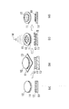
- FIG. 1 is a diagram showing a procedure for producing a mold. Specifically, first, the resist 12 is applied onto the silicon substrate 11 (FIG. 1 (a)). After the resist 12 is heat-cured by the heater 13 (FIG. 1 (b)), the resist 12 is exposed through the photomask 15 using the light source 14 to form a pattern (FIG. 1 (c)). Then, it is developed and washed to obtain a mold 10 (FIG. 1 (d)).
- FIG. 2 is a diagram showing a procedure for producing a micro stamp using the above mold. Specifically, first, with respect to the mold 10 placed in the outer container 9 (FIG. 2 (a)), the rubber tube 21 is placed (FIG. 2 (b)), and the mold is released from the mold 10. After the mold release treatment is performed with the agent 22 (FIG. 2 (c)), the stamp material 23 such as polydimethylsiloxane (PDMS) is poured (FIG. 2 (d)). Then, by heating and curing in the constant temperature dryer 24 (FIG. 2 (e)), the micro stamp 20 is obtained (FIG. 2 (f)). The micro stamp 20 has a convex portion 20a.
- PDMS polydimethylsiloxane
- FIG. 3 shows the procedure for transcription of cell adhesion molecules by the above micro stamp.
- 3 (a), 3 (c), and 3 (e) show the flow of the procedure
- FIGS. 3 (b), 3 (d), and 3 (f) are shown in FIGS. 3 (a) and 3 (f), respectively.
- a state in which FIGS. 3 (c) and 3 (e) are viewed from the side is shown.
- a base material 32 having a surface 32a treated with water repellent was prepared (FIGS. 3A and 3B), and cell adhesion molecules were formed on the surface of the convex portion 20a of the microstamp 20. Apply 20b. Then, the convex portion 20a of the micro stamp 20 is brought into close contact with the water-repellent surface 32a of the base material 32 (FIGS. 3 (c) and 3 (d)). As a result, the pattern of the convex portion 20a of the microstamp 20 can be transferred to the water-repellent surface 32a of the base material 32 as the pattern of the cell adhesion molecule 20b (FIGS. 3 (e) and 3 (f)).
- FIG. 4 shows a procedure for pattern formation of cell adhesion molecules by the sealing method.
- 4 (a), 4 (c), and 4 (e) show the flow of the procedure
- FIGS. 4 (b), 4 (d), and 4 (f) are shown in FIGS. 4 (a) and 4 (f), respectively.
- a state in which FIGS. 4 (c) and 4 (e) are viewed from the side is shown.
- the sealing material 50 having the holes 50a is placed in close contact with the base material 32 (FIG. 4A).
- the close contact arrangement means a state in which air is not caught between the sealing material 50 and the base material 32.
- no air biting means a state in which there is no air biting that affects the pattern formation of cell adhesion molecules. For example, even if there are bubbles sufficiently small with respect to the film thickness of the sealing material 50. Good.
- the method of closely arranging them is not particularly limited. A method may be used in which the material of the sealing material 50 is applied to the entire surface of the base material 32 and then the holes 50a are formed, or the sealing material 50 in which the holes 50a are formed in advance may be attached to the base material 32.
- the cell adhesion molecule 20b is placed on the sealing material 50 (FIG. 4 (c)).
- the method of arranging the cell adhesion molecule 20b is not particularly limited. Coating, dipping, spraying and the like can be preferably used. Then, by removing the cell adhesion molecule 20b on the sealing material 50 and then removing the sealing material 50, the pattern of the cell adhesion molecule 20b can be obtained (FIG. 4 (e)).
- the thickness 20b of the finished cell adhesion molecule 20b (cell adhesion molecule region) can be easily controlled by controlling the thickness of the sealing material 50.
- the sealing material 50 needs to have a property that its component does not remain on the base material 32 when it is peeled off from the base material 32. This is because if it remains on the substrate 32, it may become a contaminant for the cells to be cultured.
- the sealing material 50 also needs to have a property that the base material 32 itself does not deteriorate after being peeled off from the base material 32. Further, the sealing material 50 is also required to have a property that it can be easily peeled off from the base material 32 and the cell adhesion molecule 20b fixed at the time of peeling is not peeled off from the base material 32.
- the material of the sealing material 50 is not particularly limited as long as it can achieve such characteristics, but resin materials such as thermosetting resins, thermoplastic resins, and photocurable resins, and peptide materials typified by gelatin and the like can be used. Paper, clay (mixture of inorganic substance and resin) and the like can be preferably used.
- a cell culture kit in which the sealing material 50 in which the pores 50a are formed on the base material 32 in advance is formed is effective.
- the cell adhesion molecule 20b uses a material of the user's preference.
- Such a cell culture kit can be said to be a cell culture kit for spheroid formation in which a sealing material 50 having holes 50a formed in a base material 32 having a water-repellent surface 32a is closely arranged.
- a cell culture kit in which the cell adhesion molecule 20b is arranged in the pore 50a may be used.
- Such a cell culture kit can be said to be a cell culture kit for spheroid formation in which a sealing material 50 having pores 50a formed on the substrate 32 is formed and cell adhesion molecules 20b are arranged in the pores 50a.
- the holes 50a formed in the sealing material 50 are arranged with holes 50a having similar shapes of different sizes.
- the quality of spheroids in the cells to be cultured may differ depending on the size of the cell adhesion molecule region. Therefore, if the sealing material 50 having pores 50a having different sizes is arranged on the base material 32, it is easy to determine how much cell adhesion molecule region should be formed when culturing cells for the first time. You can look it up in.
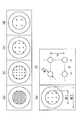
- FIG. 5A exemplifies a cell culture kit for spheroid formation in which pores 50a having different sizes are formed.
- the base material 32 exists behind the sealing material 50.
- the holes 50aa, the holes 50ab, the holes 50ac, and the holes 50ad become smaller holes 50a in this order.
- the sealing material 50 may be provided with a protruding portion or a tab at the end portion for gripping at the time of peeling so that the sealing material 50 can be easily peeled off.
- FIG. 5B shows a cell culture kit for spheroid formation in which a protrusion 52 is formed.
- the base material 32 exists behind the sealing material 50.
- the protruding portion 52 is a portion protruding from the sealing material 50 in the same plane.
- FIG. 5C shows a cell culture kit for spheroid formation in which tabs 54 are arranged.
- FIG. 5 (d) is a side view of the cell culture kit for spheroid formation shown in FIG. 5 (c).
- the tab 54 is a film sandwiched between the base material 32 and the sealing material 50. When the sealing material 50 is peeled off, the sealing material 50 can be peeled off from the base material 32 by sandwiching the tab with tweezers or the like and pulling it.
- Cell culture The cell culture will be described below with reference to FIG. When cells are cultured in the culture medium 41 using the cell culture scaffold of the present invention, as shown in FIG. 6, cells are found on the surface of the cell adhesion molecule 20b patterned on the water-repellent surface 32a of the substrate 32. Multiply.
- the cell culture may be carried out by a usual method except that the cell culture scaffold according to the present invention is used.
- the interface between the water-repellent surface 32a and the cell adhesion molecule 20b has adhesiveness that does not easily peel off, but with the passage of time, the interface between the water-repellent surface 32a and the cell adhesion molecule 20b adheres. The sex is reduced.
- the cell adhesion molecule 20b is naturally exfoliated due to the decrease in adhesive strength.
- the cell adhesion molecule 20b can be peeled off by stimulating the interface with reduced adhesive strength by pipetting or the like.
- the cell culture 42 floats in the culture solution 41, and by collecting this, the cell culture 42 can be recovered without being destroyed.
- the cell adhesion molecule 20b is surrounded and floats together in the cell culture 42.
- adhesive cells are basically assumed. Although not particularly limited, examples thereof include epithelial-like cells, mesenchymal cells, and fibrous cells.
- pluripotent stem cells such as ES cells and iPS cells, tissue-based stem cells, progenitor cells, and the like are also included in the application targets.
- ⁇ Cell adhesion molecule> Fibronectin (5 ⁇ g / cm 2 ): Fibronectin solution, derived from human plasma (063-05591 / Wako) (2) Vitronectin (1 ⁇ g / cm 2 ): rhVTN (220-02041 / Wako) (3) Matrigel (250-340 ⁇ g / ml): Corning Matrigel Basement Membrane Matrix, GFR (354230 / Corning) (4) Collagen (1.6 ⁇ g / ml): Collagen type IV derived from bovine lens (acid extraction) (0.5 mg / ml) (ASC-4-104-01 / Nippi)
- (1-2) Culture solution A mixed solution of (a): (b): (c): (d): (e) 100 mL: 390 mL: 5 mL: 5 mL: 3.5 ⁇ l was used.
- (a) to (e) are each (A) SSR (191-18375 / Wako) (B) DMEM-F12 (046-322275 / Wako) (C) 200 mM L-alanyl-L-glutamine (01102-82 / Nakarai) (D) MEM non-essential amino acid solution (16224004 / Nakarai) (E) 2-Mercaptoethanol (135-07522 / Wako) Is.
- DMEM medium 4.75 g of Dulbecco's modified Eagle's medium (DMEM) is dissolved in ultrapure water to obtain 500 ml of a solution. Mix in a stirrer for 30 minutes, autoclave and store.
- DMEM Dulbecco's modified Eagle's medium
- MMC solution Prepare a solution with the following composition.
- Dispase solution (200 PU / ml) Prepare a solution with the following formulation.
- Dispase II 0.25g DMEM 150ml After dissolution and sterilization by filtration through a 0.22 um filter, 1 ml each is dispensed into a 15 ml centrifuge tube and stored at ⁇ 20 ° C. (200 PU / ml). At the time of use, 9 ml of DMEM is further added and diluted 10-fold before use.
- Cryopreservation solution DAP213 2M DMSO, 1M acetamide, 3M propylene glycol / human iPS cell medium (DAP213) is prepared by the following procedure. Dissolve 0.59 g acetamide in about 6 ml of iPS medium. Filter sterilize with a 0.22 ⁇ m filter and transfer to a 15 ml centrifuge tube. Add 1.42 ml of DMSO and 2.2 ml of propylene glycol. Mes up to 10 ml with medium, mix well, dispense 0.5 ml each into cryotubes and store at -80 ° C. It can be thawed and frozen several times.
- the DAP to be added may be 200 ⁇ l regardless of the number of frozen cells. 12) Freeze in liquid nitrogen for 30 seconds to 1 minute to completely freeze the inside. 13) Transfer to a liquid nitrogen storage container.
- the cell suspension is collected in a 15 ml centrifuge tube and centrifuged at 1500 rpm for 3-5 minutes. 5) The supernatant is aspirated and discarded, and 1 ml of human iPS cell medium is added. Gently pipette and suspend the iPS cell colonies to the extent that they do not become too small. For large colonies, lightly press the tip of the pipette that sucked up the cell suspension against the bottom of the centrifuge tube to gently drain the cell suspension and loosen it. 6) Remove the feeder cell medium by suction and add 3 ml of human iPS cell medium. 7) Seed the whole amount and add the bFGF solution to 15 ng / ml.
- (2-2) Culture solution A mixed solution of (a): (b) 50: 450 (mL) was used. However, in the above, (a) and (b) are respectively.
- DMEM medium Dulbecco's modified Eagle's medium (DMEM; Nissui 05919): 433 ml (4.75 g dissolved in ultrapure water and autoclaved) 10% w / w NaHCO 3 (Nakarai) solution: 7 ml (dissolve in 0.7 g ultrapure water and autoclave) 200 mM L-glutamine (Nacalai) solution: 10 ml (0.292 g dissolved in ultrapure water and filtration) FBS (Bioest): 50 ml (deactivated)
- Hek293 1) Discard the medium by suction and add an appropriate amount of PBS (-). 2) Collect cells by pipetting, use several tens of ⁇ l to count the number of cells, and centrifuge the rest at 1500 rpm / 3 minutes. 3) to seed cells in a 4-well dish 3.0 ⁇ 10 5 / well. 4) Incubate in an incubator. Medium is changed every 2 days.
- the table below summarizes the dimensions of each photomask.
- ⁇ 1 to ⁇ 3 and d are as shown in FIGS. 7 (e) and 7 (f).
- ⁇ 1 is the diameter of the inner circle of the mask
- ⁇ 2 is the diameter of the outer circle of the mask
- ⁇ 3 is the diameter of the mask.
- the diameter of each dot, d is the distance between the center points of adjacent dots.
- a resist is applied on a silicon substrate, the resist is heated and solidified with a heater, and then exposed, developed, and washed through each of the photomasks, and the mold is formed. Was produced.
- micro stamps were prepared using the four types of molds prepared above.
- PDMS polydimethylsiloxane
- each micro stamp will be referred to as a micro stamp 1 to 4 in correspondence with the photomasks 1 to 4 in Table 2 above.
- the cells were cultured using the iPS cells prepared above using DMEM + 10% FBS as a medium in an environment of 37 ° C. and a CO 2 concentration of 5%.
- the number of seeded cells was 1.6 ⁇ 10 5 cells / cm 2 , the culture period was 10 days, and after 10 days, extremely weak stimulation by pipetting was applied to detach the cells from the scaffold, and the detached cells were removed. It was observed with a phase contrast microscope. Observation was performed every day or every other day, and medium exchange was performed every other day.
- other cells are prepared by forming various cell adhesion molecules on the fluororesin layer in a dot shape (about 1000 ⁇ m in diameter for fibronectin and vitronectin, about 1500 ⁇ m in diameter for fibronectin and vitronectin) using a pipette.
- the cell culture scaffold was used.
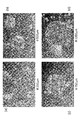
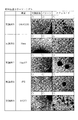
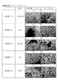
- FIG. 8 (a) is a photograph of Example 1
- FIG. 8 (b) is a photograph of Example 2
- FIG. 8 (c) is a photograph of Example 3
- FIG. 8 (d) is a photograph of a cell culture before exfoliation of Example 4.
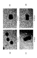
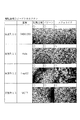
- FIG. 9 (a) is a photograph of Example 1
- FIG. 9 (b) is a photograph of Example 2
- FIG. 9 (c) is a photograph of Example 3
- FIG. 9 (d) is a photograph of a cell culture after exfoliation of Example 4. ..
- ⁇ When the cell aggregate can be regarded as spherical with sufficient thickness and size three-dimensionally ⁇ : When the cell aggregate has a certain thickness and size three-dimensionally ⁇ : Most of the cells aggregate If it is not and is dispersed two-dimensionally (if it is thick, the transmitted light is reduced and the color looks dark when observed under a microscope).
- cell cultures are formed in various combinations of cultured cells and cell adhesion molecules, and the cells are suspended in the culture medium and recovered without being destroyed. I found that I could do it.
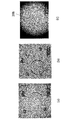
- FIG. 14 illustrates the pattern of the cell adhesion molecule 20b produced by the sealing method.
- a flat quartz substrate spin-coated with a fluororesin (Cytop CTX-809A, manufactured by AGC Inc.) was used.
- the sealing material 50 was formed by spin-coating a base material 32 with an ultraviolet curable resin (manufactured by DYMAX), curing with ultraviolet rays using a negative pattern of a dot pattern as a mask, and then removing the uncured portion.
- FIG. 14A shows a sealing material 50 having four holes 50a formed on the base material 32.
- the scale bar is 10 mm.
- FIG. 14B shows a state in which the sealing material 50 is peeled off from the base material 32. Even if the sealing material 50 was peeled off from the base material 32, the components of the sealing material 50 did not remain on the base material 32 and could be peeled off cleanly.
- FIG. 14C shows a patterned cell adhesion obtained by applying the cell adhesion molecule 20b in a state where the sealing material 50 is formed on the base material 32, fixing the cell adhesion molecule 20b for 1 hour, and then peeling the sealing material 50.
- It is a photograph of a molecule 20b (cell adhesion molecule region).
- a cylindrical cell adhesion molecule 20b having a diameter of 1 mm and a thickness of 0.1 mm could be obtained.
- the cell adhesion molecule 20b on the substrate 32 is the cell culture scaffold according to the present invention.
- the cell culture kit for spheroid formation according to the present invention is obtained by closely arranging the sealing material 50 having holes 50a formed on the base material 32 of FIG. 14A.
- spheroids were prepared using the cell culture scaffold prepared by the sealing method.
- Matrigel was added from above the sealing material 50 (arrangement of cell adhesion molecules), and the cells were fixed in the incubator at 37 ° C. for 1 hour.
- the sealing material 50 was peeled off with flame-sterilized tweezers to obtain a cell culture scaffold in which cell adhesion molecule (Matrigel) dots having a diameter of 1000 ⁇ m were patterned.
- the cells (Hek293) used in Examples 5, 10 and 14 were seeded on the base material 32.
- the cells were cultured by the same culture method as in the above example (the method described in "(2-4) Culture procedure"). After seeding the cells, the cells were peeled off from the substrate 32 by pipetting on the 5th day, and the cells were observed on the 6th day.
- the cell culture scaffold according to the present invention can be suitably used for obtaining a spheroid-like cell culture.
Landscapes
- Health & Medical Sciences (AREA)
- Life Sciences & Earth Sciences (AREA)
- Engineering & Computer Science (AREA)
- Wood Science & Technology (AREA)
- Organic Chemistry (AREA)
- Bioinformatics & Cheminformatics (AREA)
- Chemical & Material Sciences (AREA)
- Zoology (AREA)
- Biomedical Technology (AREA)
- Biotechnology (AREA)
- Genetics & Genomics (AREA)
- Microbiology (AREA)
- Biochemistry (AREA)
- General Engineering & Computer Science (AREA)
- General Health & Medical Sciences (AREA)
- Sustainable Development (AREA)
- Immunology (AREA)
- Cell Biology (AREA)
- Clinical Laboratory Science (AREA)
- Apparatus Associated With Microorganisms And Enzymes (AREA)
- Micro-Organisms Or Cultivation Processes Thereof (AREA)
Abstract
細胞培養後、細胞培養物を破壊することなく回収することができる細胞培養足場及び細胞培養物の作製方法を提供することを課題とする。 本発明にかかる細胞培養足場は、撥水性表面を有する基材と、前記基材の撥水性表面に形成された細胞接着分子とを備える。また、本発明にかかる細胞培養物の作製方法は、上記細胞培養足場を用いて、上記細胞接着分子表面で細胞を培養する工程を含む。本発明に係る細胞培養足場は、細胞をダメージなくスフェロイド状で回収することができる。
Description
本発明は、細胞を培養するための細胞培養足場と、この細胞培養足場を用いて細胞培養物(特に三次元細胞集合体)を作製する方法に関する。
細胞培養後に、細胞培養物を培養足場から剥離する方法としては、酵素を用いる方法が知られている。しかし、この方法では、細胞間の結合を壊さずに、細胞培養物を回収することが困難である。
また、細胞培養足場に温度応答性ポリマーを用い、熱処理を行って温度応答性ポリマーを分解することにより、細胞培養物を培養足場から剥離し、回収する方法も知られている(例えば、特許文献1等参照。)。
また、再生医療においては、培養した細胞をスフェロイドとして回収したい要求が高い。細胞をスフェロイドに培養する点については、非特許文献1などが提案されている。ここでは、ポリテトラフルオロエチレン(PTFE)面上にハイドロキシアパタイトのドットパターンを形成し、そのうえで細胞を培養し、スフェロイドを形成している。
また、細胞担体とし、疎水性基材にタンパク質、ペプチドといった細胞外マトリックスをコートした基材も知られている(特許文献2)
田村他「細胞/スフェロイドアレイを目的としたアパタイトドット作製法の検討」生体医工学シンポジウム2013(予稿集p.141),2013年9月20日発表
特許文献1の方法は、培養―剥離のプロセスを狭いマージンの温度管理下で行うことが必要であるため、温度コントロールが困難であり、また、サイズコントロールも容易ではない。
非特許文献1は、細胞をスフェロイド様に培養する点の記載はあるものの、これを基材から剥離させるという点の知見はない。特許文献2は疎水性基材上に細胞外マトリックスをコートした記載はあるものの、そもそもスフェロイドを形成しようとするものでははい。
非特許文献1は、細胞をスフェロイド様に培養する点の記載はあるものの、これを基材から剥離させるという点の知見はない。特許文献2は疎水性基材上に細胞外マトリックスをコートした記載はあるものの、そもそもスフェロイドを形成しようとするものでははい。
従来細胞を、3次元的に集合したスフェロイドに培養し、回収しようとすると、以下の問題点があった。
(1)スフェロイドができても劣化なく基板から剥がすことができない。
(2)大きさが不均一な浮遊スフェロイドしか作製できない。
(3)構成する全ての細胞が分化誘導したスフェロイドを作製できない。
(4)スフェロイドを構成する全ての細胞に、適切な細胞極性を持たせた状態のスフェロイドを作製できない。
上記の先行文献はこれらの課題を解決できず、細胞のスフェロイドを回収することができなかった。
(1)スフェロイドができても劣化なく基板から剥がすことができない。
(2)大きさが不均一な浮遊スフェロイドしか作製できない。
(3)構成する全ての細胞が分化誘導したスフェロイドを作製できない。
(4)スフェロイドを構成する全ての細胞に、適切な細胞極性を持たせた状態のスフェロイドを作製できない。
上記の先行文献はこれらの課題を解決できず、細胞のスフェロイドを回収することができなかった。
そこで、本発明は、細胞培養後、細胞培養物を破壊することなく回収することができる細胞培養足場とこれを用いた細胞培養物の作製方法を提供することを目的とする。
本発明は、上記課題を解決するため、以下の構成を備える。
すなわち、本発明にかかる細胞培養足場は、フッ素樹脂による撥水性表面を有する基材と、前記基材の撥水性表面に形成された細胞接着分子とを備える。
また、本発明にかかる細胞培養物の作製方法は、上記細胞培養足場を用いて、上記細胞接着分子表面で細胞を培養する工程を含む。
すなわち、本発明にかかる細胞培養足場は、フッ素樹脂による撥水性表面を有する基材と、前記基材の撥水性表面に形成された細胞接着分子とを備える。
また、本発明にかかる細胞培養物の作製方法は、上記細胞培養足場を用いて、上記細胞接着分子表面で細胞を培養する工程を含む。
本発明にかかる細胞培養足場を用いて細胞を培養すると、細胞培養開始後、一定期間はフッ素樹脂による撥水性表面と細胞接着分子との界面が強固に接着しているが、さらに一定期間経過すると前記界面の接着性が低下する。この経時的な接着性の変化を利用することによって、一定の段階まで細胞を培養したのち、細胞培養足場から、細胞培養物を破壊することなく浮遊させることができる。しかも、細胞接着分子をパターン状に形成することで、細胞培養物が三次元的に集合した三次元細胞集合体として回収できる。また、この三次元細胞集合体は、互いに大きさが同じ程度のものが多数回収できる。さらに、温度応答性ポリマーを用いる場合のような温度コントロールの困難性もなく、また、サイズコントロールが容易なことも本発明の優位点である。
したがって、2次元的に培養した幹細胞に誘導因子を添加し、細胞極性を形成した後に、それを維持したまま適切なタイミングで細胞にダメージが少ないピペッティング等の操作で細胞を基材から剥がすことにより、3次元のスフェロイドを形成させることができると考えられ、従来スフェロイドを得る際に問題となった上記の課題を解決することができる。
以下、本発明にかかる細胞培養足場及び細胞培養物の作製方法について詳しく説明するが、本発明の範囲はこれらの説明に拘束されることはなく、以下の例示以外についても、本発明の趣旨を損なわない範囲で適宜変更実施し得る。
〔基材〕
本発明における基材は、フッ素樹脂による撥水性表面を有する。
このような撥水性表面を有する基材としては、例えば、シャーレ、ウェル、プレート、マルチプレート、フラスコなどの基材がフッ素樹脂以外の材料からなり、当該基材の表面にフッ素樹脂層をコーティングしたものを用いることができる。
フッ素樹脂以外の材料からなる基材としては、例えば、ポリスチレンなどのプラスチック製やガラス製などの既存の基材を用いることができる。フッ素樹脂層が容易に剥離しないものを適宜選択すれば良い。
本発明における基材は、フッ素樹脂による撥水性表面を有する。
このような撥水性表面を有する基材としては、例えば、シャーレ、ウェル、プレート、マルチプレート、フラスコなどの基材がフッ素樹脂以外の材料からなり、当該基材の表面にフッ素樹脂層をコーティングしたものを用いることができる。
フッ素樹脂以外の材料からなる基材としては、例えば、ポリスチレンなどのプラスチック製やガラス製などの既存の基材を用いることができる。フッ素樹脂層が容易に剥離しないものを適宜選択すれば良い。
基材上に、フッ素樹脂層を形成する方法としては、特に限定されず、例えば、スピンコーティング、ディップコーティング、スプレーコーティングなどの公知の塗布手段により、基材上にフッ素樹脂層を塗布し、加熱するなどして硬化することにより、形成することができる。
また、上記と異なり、フッ素樹脂製のシャーレなど、基材の材料としてフッ素樹脂が用いられたものであっても良く、このような基材も、本発明にいう「フッ素樹脂による撥水性表面を有する基材」に含まれる。
フッ素樹脂としては、公知のフッ素樹脂を用いることができ、例えば、ポリテトラフルオロエチレン、ポリクロロトリフルオロエチレン、ポリフッ化ビニリデン、ポリフッ化ビニル、ペルフルオロアルコキシフッ素樹脂、四フッ化エチレン・六フッ化プロピレン共重合体、エチレン・四フッ化エチレン共重合体、エチレン・クロロトリフルオロエチレン共重合体などが好ましく挙げられる。
〔細胞接着分子〕
細胞接着分子は、例えば、コラーゲン、ビトロネクチン、フィブロネクチン、ラミニン、エラスチン、ヘパラン硫酸、プロテオグリカンなどの細胞外マトリックスやそれらの細胞接着部位を断片化した分子、ポリリジン、ポリエチレンイミン、ポリアリルアミン塩酸塩などのカチオン性高分子などが挙げられる。
このような細胞接着分子自体は、従来公知であり、培養する細胞の種類などに応じて適宜選択することができる。
細胞接着分子は、例えば、コラーゲン、ビトロネクチン、フィブロネクチン、ラミニン、エラスチン、ヘパラン硫酸、プロテオグリカンなどの細胞外マトリックスやそれらの細胞接着部位を断片化した分子、ポリリジン、ポリエチレンイミン、ポリアリルアミン塩酸塩などのカチオン性高分子などが挙げられる。
このような細胞接着分子自体は、従来公知であり、培養する細胞の種類などに応じて適宜選択することができる。
〔細胞培養足場〕
本発明の細胞培養足場は、上記撥水性表面を有する基材と、上記基材の撥水性表面に形成された細胞接着分子とを備える。
本発明の細胞培養足場は、上記撥水性表面を有する基材と、上記基材の撥水性表面に形成された細胞接着分子とを備える。
基材の撥水性表面に細胞接着分子を形成する方法としては、例えば、スピンコーティング、ディップコーティング、スプレーコーティングなどの公知の塗布手段により行うことができる。
また、単純にコーティングするのではなく、細胞接着分子を、基材の撥水性表面にパターン状に形成してもよい。
また、単純にコーティングするのではなく、細胞接着分子を、基材の撥水性表面にパターン状に形成してもよい。
ここで「パターン状」を説明する。撥水性表面を有する基材上に細胞接着分子を連続的に形成した領域を細胞接着分子領域と呼ぶ。細胞接着分子領域は、基材との間に境界となる縁を有する。つまり、縁は、細胞接着分子領域と基材表面の境である。
「パターン状」とは、細胞接着分子領域が基材上に少なくとも1つ以上、好ましくは複数個所形成された状態をいう。各細胞接着分子領域は、同一形状でなくてもよく、また、大きさが異なってもよい。なお、細胞接着分子領域を単に細胞接着分子とも呼ぶ。
「パターン状」とは、細胞接着分子領域が基材上に少なくとも1つ以上、好ましくは複数個所形成された状態をいう。各細胞接着分子領域は、同一形状でなくてもよく、また、大きさが異なってもよい。なお、細胞接着分子領域を単に細胞接着分子とも呼ぶ。
細胞接着分子をパターン状に形成する場合、培養細胞を三次元細胞集合体として回収することができる。
ここで、三次元細胞集合体は、細胞が三次元的に集合したものである。三次元的な細胞のコロニーはスフェロイドと呼ばれる。また、複数種の細胞からなり、臓器に特異的な種類の細胞の集合体はオルガノイドと呼ばれる。
このような三次元細胞集合体においては、二次元細胞培養物では発現されない組織としての機能の発現が認められ、人体を使用せずに薬品などの効果を確認するなど、種々の利用方法が期待されている。しかし、従来、三次元細胞集合体を破壊することなく、回収することは困難であった。
従って、本発明は、上記のごとき三次元細胞集合体を破壊することなく回収する手段として、極めて有効であり、しかも、温度応答性ポリマーを用いる場合のような温度コントロールの困難性もなく、また、サイズコントロールが容易であるという利点をも有する。
例えば、細胞接着分子をドット状(略円形形状)にパターン形成することにより、各ドットの大きさに依存した大きさの三次元細胞集合体を形成させることができる。
この場合、ドット(細胞接着分子領域)の大きさとしては、例えば、直径100~1000μmとすることができる。培養する細胞を5~25μm程度とすると、細胞接着分子領域が小さすぎるとスフェロイドが小さくなり、組織細胞としては不十分である。一方、接着分子領域が大きすぎると、内部の細胞が壊死してしまう。
なお、本発明においては、上記ドット状に限らず、目的に応じて、種々のパターン形状を採用し得ることはいうまでもない。
この場合、ドット(細胞接着分子領域)の大きさとしては、例えば、直径100~1000μmとすることができる。培養する細胞を5~25μm程度とすると、細胞接着分子領域が小さすぎるとスフェロイドが小さくなり、組織細胞としては不十分である。一方、接着分子領域が大きすぎると、内部の細胞が壊死してしまう。
なお、本発明においては、上記ドット状に限らず、目的に応じて、種々のパターン形状を採用し得ることはいうまでもない。
細胞接着分子のパターン形成は、特に限定するわけではないが、例えば、インクジェットプリンタによる方法や、スタンプ法、シール法などが挙げられる。スタンプ法では、マイクロメートルオーダーで大きさを制御することも可能であり、好ましい。
また、シール法では、予め基材に、細胞接着分子のパターン(大きさ、厚さ)形状の貫通孔を有するシール材を用いることで、細部接着分子のパターン形成に手技の習熟性を必要とせず、容易にかつ正確に細胞接着分子のパターンを形成することができる。
細胞接着分子のパターン状の貫通孔を有するシール材を基材に貼り付けておき、細胞接着分子を塗布し、その後シール材を剥がすことで、細胞接着分子のパターン形成を行うこともできる。
細胞接着分子のパターン状の貫通孔を有するシール材を基材に貼り付けておき、細胞接着分子を塗布し、その後シール材を剥がすことで、細胞接着分子のパターン形成を行うこともできる。
スタンプ法の手順について、図1、2を参照して、以下に説明する。
図1は鋳型作製の手順を示す図である。
具体的には、まず、シリコン基板11上にレジスト12を塗布する(図1(a))。ヒーター13でレジスト12を加熱硬化したのち(図1(b))、光源14を用いて、フォトマスク15を通して露光してパターンを形成する(図1(c))。その後、現像、洗浄して、鋳型10が得られる(図1(d))。
図1は鋳型作製の手順を示す図である。
具体的には、まず、シリコン基板11上にレジスト12を塗布する(図1(a))。ヒーター13でレジスト12を加熱硬化したのち(図1(b))、光源14を用いて、フォトマスク15を通して露光してパターンを形成する(図1(c))。その後、現像、洗浄して、鋳型10が得られる(図1(d))。
図2は上記鋳型を用いたマイクロスタンプ作製の手順を示す図である。
具体的には、まず、外容器9内に載置した鋳型10に対して(図2(a))、ゴム管21を配置した状態(図2(b))で、上記鋳型10に離型剤22で離型処理を施した(図2(c))後、ポリジメチルシロキサン(PDMS)などのスタンプ材料23を流し込む(図2(d))。その後、定温乾燥機24内で加熱硬化することにより(図2(e))、マイクロスタンプ20が得られる(図2(f))。マイクロスタンプ20は、凸部20aを有している。
具体的には、まず、外容器9内に載置した鋳型10に対して(図2(a))、ゴム管21を配置した状態(図2(b))で、上記鋳型10に離型剤22で離型処理を施した(図2(c))後、ポリジメチルシロキサン(PDMS)などのスタンプ材料23を流し込む(図2(d))。その後、定温乾燥機24内で加熱硬化することにより(図2(e))、マイクロスタンプ20が得られる(図2(f))。マイクロスタンプ20は、凸部20aを有している。
次に、図3に、上記マイクロスタンプによる細胞接着分子の転写の手順を示す。図3(a)、図3(c)、図3(e)は手順の流れを示し、図3(b)、図3(d)、図3(f)は、それぞれ図3(a)、図3(c)、図3(e)を側面視した状態を示す。
図3を参照して、まず、表面32aを撥水処理した基材32を用意し(図3(a)、図3(b))、上記マイクロスタンプ20の凸部20a表面に、細胞接着分子20bを塗布する。そして、マイクロスタンプ20の凸部20aを、基材32の撥水性表面32aに密着させる(図3(c)、図3(d))。これにより、マイクロスタンプ20の凸部20aのパターンを基材32の撥水性表面32aに細胞接着分子20bのパターンとして転写することができる(図3(e)、図3(f))。
次にシール法について説明する。図4はシール法による細胞接着分子のパターン形成の手順を示す。図4(a)、図4(c)、図4(e)は手順の流れを示し、図4(b)、図4(d)、図4(f)は、それぞれ図4(a)、図4(c)、図4(e)を側面視した状態を示す。
基材32に対して、孔50aが形成されたシール材50を密着配置させる(図4(a))。ここで密着配置とは、シール材50と基材32の間に空気の咬み込みがない状態をいう。なお、空気の咬み込みがないとは、細胞接着分子のパターン形成に影響するような空気の咬み込みがない状態をいい、例えば、シール材50の膜厚に対して十分小さな気泡はあってもよい。
密着配置のさせ方は特に限定されない。シール材50の材料を基材32の全面に塗布してから孔50aを形成する方法であってもよいし、予め孔50aが形成されたシール材50を基材32に貼り付けてもよい。
基材32に対して、孔50aが形成されたシール材50を密着配置させる(図4(a))。ここで密着配置とは、シール材50と基材32の間に空気の咬み込みがない状態をいう。なお、空気の咬み込みがないとは、細胞接着分子のパターン形成に影響するような空気の咬み込みがない状態をいい、例えば、シール材50の膜厚に対して十分小さな気泡はあってもよい。
密着配置のさせ方は特に限定されない。シール材50の材料を基材32の全面に塗布してから孔50aを形成する方法であってもよいし、予め孔50aが形成されたシール材50を基材32に貼り付けてもよい。
次にシール材50の上から細胞接着分子20bを配置する(図4(c))。細胞接着分子20bの配置の方法は特に限定されない。塗布、ディップ、スプレー等が好適に利用できる。そして、シール材50上の細胞接着分子20bを除去してからシール材50を除去することで、細胞接着分子20bのパターンを得ることができる(図4(e))。
シール法では、シール材50の厚みを制御することで、出来上がりの細胞接着分子20b(細胞接着分子領域)の厚み20bhを容易に制御することができる。
シール材50は、基材32から剥がす際に基材32にその成分が残らない特性が必要である。基材32上に残ると、培養する細胞に対する汚染物となる可能性もあるからである。
シール材50は、基材32から剥がす際に基材32にその成分が残らない特性が必要である。基材32上に残ると、培養する細胞に対する汚染物となる可能性もあるからである。
また、シール材50は基材32から剥がした後に、基材32自体が劣化しない特性も必要となる。また、シール材50は、基材32から容易に剥がすことができ、引きはがしの際に定着させた細胞接着分子20bを基材32から剥がさない特性も必要である。
このような特性を達成できる材料であれば、シール材50の材質に特に限定はないが、熱硬化性樹脂、熱可塑性樹脂、光硬化性樹脂といった樹脂材やゼラチン等に代表されるペプチド材、紙、粘土(無機物と樹脂の混合物)等が好適に利用できる。
なお、基材32上にシール材50を密着配置させるのに、貼り付けで行うには手技の成熟度が要求される。したがって、予め基材32上に孔50aが形成されたシール材50を形成した細胞培養キットは有効である。細胞接着分子20bは、利用者が好みの材料を用いるのである。このような細胞培養キットは、撥水性表面32aを有する基材32に孔50aが形成されたシール材50が密着配置されたスフェロイド形成用細胞培養キットと言ってよい。
また、もちろん、細胞接着分子20bを孔50a内に配置したものと細胞培養キットとしてもよい。このような細胞培養キットは、基材32上に孔50aが形成されたシール材50を形成し、孔50a中に細胞接着分子20bを配置したスフェロイド形成用細胞培養キットと言ってよい。
また、もちろん、細胞接着分子20bを孔50a内に配置したものと細胞培養キットとしてもよい。このような細胞培養キットは、基材32上に孔50aが形成されたシール材50を形成し、孔50a中に細胞接着分子20bを配置したスフェロイド形成用細胞培養キットと言ってよい。
また、スフェロイド形成用細胞培養キットにおいては、シール材50に形成される孔50aが、大きさの異なる相似形状の孔50aが配置されているものは望ましい。本発明に係る細胞培養足場では、細胞接着分子領域の大きさで培養される細胞のスフェロイドの出来具合が異なる場合がある。そのため、大きさの異なる孔50aが形成されたシール材50が基材32上に配置されていれば、初めての細胞を培養する場合、どの程度の細胞接着分子領域を形成すればよいかを容易に調べることができる。
図5(a)には、大きさの異なる孔50aが形成されたスフェロイド形成用細胞培養キットを例示する。基材32はシール材50の裏に存在する。孔50aa、孔50ab、孔50ac、孔50adは、この順で小さい孔50aとなる。もちろん、孔50aの配置や大きさのバリエーションに限定はない。
さらに、シール材50は剥がしやすいように、端部に剥離時に把持するための突出部若しくはタブが配置されていてもよい。図5(b)には、突出部52が形成されたスフェロイド形成用細胞培養キットを示す。基材32はシール材50の後ろに存在する。突出部52は、シール材50から同一平面内で突き出た部分である。
また、図5(c)には、タブ54を配したスフェロイド形成用細胞培養キットを示す。図5(d)は図5(c)のスフェロイド形成用細胞培養キットの側面視である。
タブ54は、基材32とシール材50の間に挟み込まれたフィルムである。シール材50を剥離させる場合はピンセット等でこのタブを挟んで引っ張ることで、シール材50を基材32から剥離させることができる。
タブ54は、基材32とシール材50の間に挟み込まれたフィルムである。シール材50を剥離させる場合はピンセット等でこのタブを挟んで引っ張ることで、シール材50を基材32から剥離させることができる。
〔細胞培養〕
細胞培養について、図6を参照しつつ、以下に説明する。
本発明の細胞培養足場を用いて、培養液41中で細胞培養を行うと、図6に示すように、基材32の撥水性表面32aにパターン形成された細胞接着分子20bの表面で細胞が増殖する。
細胞培養は、本発明にかかる細胞培養足場を用いることを除けば、通常の方法により行えば良い。
細胞培養について、図6を参照しつつ、以下に説明する。
本発明の細胞培養足場を用いて、培養液41中で細胞培養を行うと、図6に示すように、基材32の撥水性表面32aにパターン形成された細胞接着分子20bの表面で細胞が増殖する。
細胞培養は、本発明にかかる細胞培養足場を用いることを除けば、通常の方法により行えば良い。
細胞培養初期においては、撥水性表面32aと細胞接着分子20bとの界面は容易に剥離しない接着性を有しているが、時間の経過とともに撥水性表面32aと細胞接着分子20bとの界面の接着性が低下する。
接着力の低下により、自然に細胞接着分子20bが剥離する。あるいは、接着力が低下した界面にピペッティングなどで刺激を与えることにより細胞接着分子20bを剥離することもできる。
細胞接着分子20bが剥離すると、培養液41中で、細胞培養物42が浮遊するため、これを回収することにより、細胞培養物42を破壊することなく回収することができる。
この場合、細胞接着分子20bは、図6に示すように、細胞培養物42内に取り囲まれて一体となって浮遊する。
細胞接着分子20b上で幹細胞を培養し、細胞接着分子20bが基材32から剥離する前に誘導因子を添加しておくことで、幹細胞が分化した細胞をスフェロイドで回収することもできる。
この場合、細胞接着分子20bは、図6に示すように、細胞培養物42内に取り囲まれて一体となって浮遊する。
細胞接着分子20b上で幹細胞を培養し、細胞接着分子20bが基材32から剥離する前に誘導因子を添加しておくことで、幹細胞が分化した細胞をスフェロイドで回収することもできる。
本発明に適用可能な細胞としては、基本的には接着性細胞を想定している。
特に限定するわけではないが、例えば、上皮様細胞、間葉系細胞、繊維様細胞などが挙げられる。また、ES細胞やiPS細胞などの多能性幹細胞や、組織系幹細胞、前駆細胞なども適用対象に含まれる。
特に限定するわけではないが、例えば、上皮様細胞、間葉系細胞、繊維様細胞などが挙げられる。また、ES細胞やiPS細胞などの多能性幹細胞や、組織系幹細胞、前駆細胞なども適用対象に含まれる。
以下、実施例を用いて、本発明について詳しく説明するが、本発明はこれら実施例に限定されるものではない。
〔細胞接着分子及び培養細胞の準備〕
各実施例で用いた細胞接着分子及び培養細胞について、以下に説明する。
<細胞接着分子>
(1)フィブロネクチン(5μg/cm2):フィブロネクチン溶液,ヒト血漿由来(063-05591/和光)
(2)ビトロネクチン(1μg/cm2):rhVTN(220-02041/和光)
(3)マトリゲル(250-340μg/ml):Corning Matrigel 基底膜マトリックス,GFR(354230/Corning)
(4)コラーゲン(1.6μg/ml):コラーゲンタイプIV ウシレンズ由来(酸抽出)(0.5mg/ml)(ASC-4-104-01/ニッピ)
各実施例で用いた細胞接着分子及び培養細胞について、以下に説明する。
<細胞接着分子>
(1)フィブロネクチン(5μg/cm2):フィブロネクチン溶液,ヒト血漿由来(063-05591/和光)
(2)ビトロネクチン(1μg/cm2):rhVTN(220-02041/和光)
(3)マトリゲル(250-340μg/ml):Corning Matrigel 基底膜マトリックス,GFR(354230/Corning)
(4)コラーゲン(1.6μg/ml):コラーゲンタイプIV ウシレンズ由来(酸抽出)(0.5mg/ml)(ASC-4-104-01/ニッピ)
<培養細胞及びその入手元、型番>
(1)Hela:東北大学加齢医学研究所医用細胞資源センター、TKG0331
(2)HepG2:東北大学加齢医学研究所医用細胞資源センター、TKG0205
(3)A549:東北大学加齢医学研究所医用細胞資源センター、TKG0184
(4)MCF7:東北大学加齢医学研究所医用細胞資源センター、TKG0479
(5)293::理化学研究所バイオリソースセンター、RCB1637
(6)iPS 409B2:理化学研究所バイオリソースセンター、HPS0076
(1)Hela:東北大学加齢医学研究所医用細胞資源センター、TKG0331
(2)HepG2:東北大学加齢医学研究所医用細胞資源センター、TKG0205
(3)A549:東北大学加齢医学研究所医用細胞資源センター、TKG0184
(4)MCF7:東北大学加齢医学研究所医用細胞資源センター、TKG0479
(5)293::理化学研究所バイオリソースセンター、RCB1637
(6)iPS 409B2:理化学研究所バイオリソースセンター、HPS0076
<それぞれの細胞の培養条件>
(1)iPS細胞
(1-1)播種密度
28.5colony/cm2(500cells/colonyで計算)、若しくはSingle cellでは1.5×10⁵cells/cm2
(1)iPS細胞
(1-1)播種密度
28.5colony/cm2(500cells/colonyで計算)、若しくはSingle cellでは1.5×10⁵cells/cm2
(1-2)培養液
(a):(b):(c):(d):(e)=100mL:390mL:5mL:5mL:3.5μlの混合液を用いた。
但し、上記において、(a)~(e)はそれぞれ、
(a)SSR(191-18375/和光)
(b)DMEM-F12(046-32275/和光)
(c)200mM L-アラニル-L-グルタミン(01102-82/ナカライ)
(d)MEM 非必須アミノ酸溶液(16224004/ナカライ)
(e)2-メルカプトエタノール(135-07522/和光)
である。
(a):(b):(c):(d):(e)=100mL:390mL:5mL:5mL:3.5μlの混合液を用いた。
但し、上記において、(a)~(e)はそれぞれ、
(a)SSR(191-18375/和光)
(b)DMEM-F12(046-32275/和光)
(c)200mM L-アラニル-L-グルタミン(01102-82/ナカライ)
(d)MEM 非必須アミノ酸溶液(16224004/ナカライ)
(e)2-メルカプトエタノール(135-07522/和光)
である。
(1-3)剥離液
(a):(b)=0.25g:375mLの混合液を用いた。
但し、上記において、(a),(b)はそれぞれ、
(a)ディスパーゼII(38302281/和光)
(b)DMEM-F12(046-32275/和光)
である。
(a):(b)=0.25g:375mLの混合液を用いた。
但し、上記において、(a),(b)はそれぞれ、
(a)ディスパーゼII(38302281/和光)
(b)DMEM-F12(046-32275/和光)
である。
(1-4)培養の手順
培養の詳細な手順を以下に示す。
培養の詳細な手順を以下に示す。
(1-4-1)試薬
ダルベッコ変法イーグル培地(DMEM;NISSUI 05919)
D-MEM/Ham’s F-12(DMEM-F12;和光 04230795)
Stem Sure Replacement(SSR)(和光 04632275)
ウシ胎児血清(FBS;BioWest)
MEM 非必須アミノ酸溶液(100×)(ナカライ 06344-56)
200mM L-アラニル-L-グルタミン(粉末;ナカライ 01102-82)
2-メルカプトエタノール(和光 13706862)
マイトマイシンC(和光 139-18711)
エタノール(ナカライ 14713-95)
エチレングリコール(ナカライ 058-00986)
PBS(Ca、Mg不含)(ナカライ 07269-84)
ゼラチン,タイプB,粉末,細胞培養向け生体試薬(Sigma G9391-100G)
トリプシン粉末(ナカライ 35547-64)
EDTA(ナカライ 15105-35)
ディスパーゼII (和光 38302281)
ジメチルスルホキシド(DMSO;和光 043-07216)
アセトアミド(ナカライ 00117-32)
プロピレングリコール(ナカライ 29218-35)
ウシ血清アルブミン(BSA;ナカライ 01281-84)
CHAPS(和光 34104721)
線維芽細胞成長因子(塩基性)(bFGF;Peprotech AF-100-18B)
Y-27632 (Cayman 29218-35)
セルリザーバーワン(ナカライ 07485-44)
(1-4-2)試薬の調製
(1-4-2-1)L-グルタミン溶液
L-グルタミン3.212gを超純水に溶解させ、110mlの溶液を得る。
溶解後、0.22μmフィルターでろ過滅菌後、15ml遠沈管に10mlずつ分注し、-20℃で保存する。
(1-4-2-1)L-グルタミン溶液
L-グルタミン3.212gを超純水に溶解させ、110mlの溶液を得る。
溶解後、0.22μmフィルターでろ過滅菌後、15ml遠沈管に10mlずつ分注し、-20℃で保存する。
(1-4-2-2)10%NaHCO3溶液
NaHCO310gを超純水に溶解させ、10%NaHCO3溶液100mlを得る。
オートクレーブ溶解・滅菌後、室温で保存する。
NaHCO310gを超純水に溶解させ、10%NaHCO3溶液100mlを得る。
オートクレーブ溶解・滅菌後、室温で保存する。
(1-4-2-3)DMEM培地
ダルベッコ変法イーグル培地(DMEM)4.75gを超純水に溶解させ、500mlの溶液を得る。
スターラーで30分混和し、オートクレーブ後、保存する。
ダルベッコ変法イーグル培地(DMEM)4.75gを超純水に溶解させ、500mlの溶液を得る。
スターラーで30分混和し、オートクレーブ後、保存する。
(1-4-2-4)0.1%ゼラチン溶液
ゼラチン0.5gを超純水に溶解させ、500mlの溶液を得る。
オートクレーブ溶解・滅菌後、室温で保存する。
ゼラチン0.5gを超純水に溶解させ、500mlの溶液を得る。
オートクレーブ溶解・滅菌後、室温で保存する。
(1-4-2-5)MMC溶液
下記の配合で溶液を調製する。
マイトマイシンC(MMC) 10mg
エタノール 1ml
エチレングリコール 9ml
溶解後、0.22umのフィルターにてろ過滅菌し、溶液を得る。
下記の配合で溶液を調製する。
マイトマイシンC(MMC) 10mg
エタノール 1ml
エチレングリコール 9ml
溶解後、0.22umのフィルターにてろ過滅菌し、溶液を得る。
(1-4-2-6)ディスパーゼ液(200PU/ml)
下記の配合で溶液を調製する。
ディスパーゼII 0.25g
DMEM 150ml
溶解し0.22umのフィルターにてろ過滅菌後、15ml遠沈管に1mlずつ分注し、-20℃で保存する(200PU/ml)。
使用時はさらにDMEM9mlを加え10倍希釈して使用する。
下記の配合で溶液を調製する。
ディスパーゼII 0.25g
DMEM 150ml
溶解し0.22umのフィルターにてろ過滅菌後、15ml遠沈管に1mlずつ分注し、-20℃で保存する(200PU/ml)。
使用時はさらにDMEM9mlを加え10倍希釈して使用する。
(1-4-2-7)ヒトiPS細胞用培地
下記の配合で培地を調製する。
DMEM-F12 390ml
非必須アミノ酸 5ml
200mM L-グルタミン 5ml
SSR(20%) 100ml
2-メルカプトエタノール(0.1mM) 3.5μl
調製後4℃で保存し、2週間以内に使用する。
下記の配合で培地を調製する。
DMEM-F12 390ml
非必須アミノ酸 5ml
200mM L-グルタミン 5ml
SSR(20%) 100ml
2-メルカプトエタノール(0.1mM) 3.5μl
調製後4℃で保存し、2週間以内に使用する。
(1-4-2-8)basic FGF溶液
下記の配合で溶媒を溶解し、0.22umのフィルターにてろ過滅菌後、溶液を調製する。
BSA 0.05g
CHAPS 0.01g
D-PBS(-) 10ml
下記の配合で溶媒を溶解し、0.22umのフィルターにてろ過滅菌後、溶液を調製する。
BSA 0.05g
CHAPS 0.01g
D-PBS(-) 10ml
(1-4-2-9)凍結保存溶液 DAP213
以下の手順で、2M DMSO,1M アセトアミド,3M プロピレングリコール/ヒトiPS細胞用培地(DAP213)を調製する。
0.59gアセトアミドを6ml程度のiPS培地に溶解する。0.22μmフィルターで濾過滅菌し、15mlの遠心チューブへ移す。
DMSO 1.42ml、プロピレングリコール2.2mlを添加する。
培地で10mlにメスアップし、よく混ぜて、0.5mlずつクライオチューブに分注し、-80℃で保存する。数回の融解・凍結は可能である。
以下の手順で、2M DMSO,1M アセトアミド,3M プロピレングリコール/ヒトiPS細胞用培地(DAP213)を調製する。
0.59gアセトアミドを6ml程度のiPS培地に溶解する。0.22μmフィルターで濾過滅菌し、15mlの遠心チューブへ移す。
DMSO 1.42ml、プロピレングリコール2.2mlを添加する。
培地で10mlにメスアップし、よく混ぜて、0.5mlずつクライオチューブに分注し、-80℃で保存する。数回の融解・凍結は可能である。
(1-4-3)フィーダー細胞の調製
(1-4-3-1)STOもしくはマウス胎仔繊維芽細胞(MEF)の解凍
1) 10%FBS/DMEM培地を室温に戻す。
2) 10%FBS/DMEM培地8mlを15mlコニカルチューブに移す。
3) 凍結保存していた細胞を37℃ウォーターバスで完全解凍直前まで解凍する。
4) 1mlディスポーザブルピペットで、培地を入れて予め準備した15mlチューブへ移す。新しい10%FBS/DMEM培地1mlでチューブ内を洗い、残りの細胞も回収する。
5) 1,500rpm、3~5分遠心する。
6) 上清を吸引し10%FBS/DMEM培地を10ml加える。ピペッティングを十分に行い、細胞の凝集塊が残らないように懸濁する。
7) 細胞懸濁液全量をφ100ディッシュに移す。
8) 37℃、CO2インキュベーターで一晩培養し接着・増殖させる。
9) 翌日、顕微鏡で細胞の状態を観察する。10%FBS/DMEM培地を室温に戻す。
10) ディッシュ内の培地を除き、10%FBS/DMEM培地10mlをディッシュに加える。
11) 37℃、CO2インキュベーターでコンフルエントに達するまで培養する。
(1-4-3-2)マイトマイシンC処理
1) 細胞がコンフルエントに達していることを確認する。
2) φ100ディッシュに、最終濃度が10μg/mlになるようにマイトマイシンCを添加する。(10%FBS/DMEM培地10ml当たり1mg/ml マイトマイシンCストック液100μl添加。)細胞全体に液が行き渡るようディッシュを充分に揺らす。
3) 37℃、CO2インキュベーターで2-3時間静置する。
4) 2-3時間後、ディッシュ内の培地を除き、PBS(-)5ml以上で3回洗浄する。
5) 新たに10%FBS/DMEM培地10mlを加える。
6) 37℃、CO2インキュベーターで一晩培養する。
7) この状態で、ほとんどの細胞は非分裂細胞となっている。
8) PBS(-)5mlで洗浄し吸引破棄し、その後1ml 0.25%トリプシン-EDTAを加え37℃で2.5-3分静置する。
9) 10%FBS/DMEM培地3mlを加え、ピペッティングし15ml遠沈管に細胞を回収する。
10) 1,500rpm、3-5分遠心。
11) 上清を吸引し、900μl セルリザーバーワンを加え、2ml凍結チューブに200μlずつ分注し凍結保存。(1.95×10⁶cells/本、融解時φ60×2枚に播種可能)
(1-4-3-3)フィーダー細胞の作製
1) 前日に、ディッシュに0.1%ゼラチン溶液を加える(ディッシュのサイズに応じたゼラチン溶液の添加量は下表1のとおり)。
2) 37℃、CO2インキュベーターで30分以上静置する。
3) 10%FBS/DMEM培地を室温に戻し、10%FBS/DMEM培地 5mlを15mlコニカルチューブに移す。
4) 細胞を一部カウントする。
5) 凍結保存していた細胞を37℃ウォーターバスで完全解凍直前まで解凍する。
6) 1mlディスポーザブルピペットで、培地を入れて予め準備した15mlチューブへ移す。新しい10%FBS/DMEM培地1mlでチューブ内を洗い、残りの細胞も回収する。
7) 1,500rpm、3-5分遠心する。
8) 上清を吸引し10%FBS/DMEM培地を1ml加える。ピペッティングを十分に行い、細胞の凝集塊が残らないように懸濁する。
9) 細胞濃度が0.8-1.0×10⁶cells/mlになるように加えるため培地の量を計算する。
10) ゼラチン溶液を除き、計算した量の細懸濁液をφ60ディッシュに播種する。
11) 37℃、CO2インキュベーターで一晩培養する。

(1-4-3-4)ヒトiPS細胞の継代培養法
1) 前日までに、フィーダー細胞を準備する。
(以下の試薬容量は、60mm細胞培養ディッシュ1枚の場合)
2) ヒトiPS細胞用培地とディスパーゼ液を室温に戻す。
3) ディスパーゼ液0.5mlをディッシュに加え、細胞表面全体に液が行き渡るようにした後、37℃、CO2インキュベーターで3分加温する。
4) 細胞の状態を顕微鏡で観察し、ディスパーゼ液を除去する。
5) 37℃で10分インキュベーションする。半分以上のコロニーが周囲から小さくまとまり、フィーダー細胞からはがれかけている状態が望ましい。
6) ヒトiPS細胞用培地を1ml加え、細胞をディッシュからはがす。数回(10回以内)ピペッティングを行い、コロニーを適切なサイズに砕く。ギルソンP-1000を使用するとよい。(iPS細胞コロニー1つあたり約100細胞程度になるようにする。)コロニーが小さくなりすぎると再接着・増殖の効率が極端に低下する原因になるため、顕微鏡で確認しながら、コロニーを解離する。
7) 700rpm、2分遠心し、上清をできるだけ除く。
8) フィーダー細胞のディッシュから培地を除き、ヒトiPS細胞用培地を3mlずつ加える。
9) コニカルチューブに1.5-2mlの培地を加え、軽く懸濁する。既にiPS細胞は100細胞前後の適切なサイズのコロニーなっているため、激しいピペッティングを避ける。もし大きなコロニーがみえるようなら、細胞懸濁液を吸い上げたピペットの先端をコニカルチューブの底に軽く押しつけ、穏やかに細胞懸濁液を排出して細胞をほぐす。フィーダー細胞ディッシュ×1枚あたり1mlのヒトiPS細胞懸濁液を加える。15ng/mlの終濃度でbFGFを加える。(必要であれば、Y-27532溶液を10μM/mlとなるように添加する。)
10) 細胞の状態を顕微鏡で観察する。iPS細胞のコロニーがディッシュ全体に行き渡るように、ディッシュを充分に揺する。
11) 37℃、CO2インキュベーターで一晩培養する。
12) 翌日、顕微鏡で細胞の状態を観察し、培地交換する。
13) 以後毎日培地交換する。3-4日でコンフルエントになる。
(1-4-3-5)ヒトiPS細胞の凍結保存法
1) コンフルエントの状態のヒトiPS細胞をφ60ディッシュ×1枚準備する。
2) ヒトiPS細胞用培地とディスパーゼ液を室温に戻す。液体窒素と氷を準備する。
凍結保存用チューブ(Nulgene #5000-1012)に「細胞名」「日付」「継代数」等を記入し、氷上で冷やしておく。
3) 凍結保存液DAP213を解凍、氷上で冷やしておく。
4) ヒトiPS細胞ディッシュの培地を除き、適量のPBS(-)を加え洗浄し破棄する
5) ディスパーゼ液500μlをディッシュに加え、細胞表面全体に液が行き渡るようにした後、37℃、CO2インキュベーターで3分加温する。
6) 細胞の状態を顕微鏡で観察し、ディスパーゼ液を除去する。
7) 37℃で10分インキュベーションする。
8) ヒトiPS細胞用培地を3ml加え、細胞全体をディッシュからはがす。
9) 細胞を15ml遠沈管に回収する。
10) 1500rpm、3-5分遠心し、上清をできるだけ除く。
11) DAP213を200μl加え、穏やかに懸濁する。予め準備した凍結保存用チューブに移す。ピンセットで凍結チューブをつかみ、液体窒素につける。DAPは細胞毒性が強いため出来る限りすばやく作業するように留意する。目安として15秒以内が望ましい。また、加えるDAPは、凍結する細胞数に関係なく200μlで良い。
12) 液体窒素中で、30秒から1分凍結し、内部まで完全に凍らせる。
13) 液体窒素保存容器に移す。
(1-4-3-6)ヒトiPS細胞の解凍
1) 前日までに、ヒトiPS細胞の凍結チューブ1本あたりφ60ディッシュ×1枚分のフィーダー細胞を用意する。
2) ヒトiPS細胞用培地10mlを15mlコニカルチューブに移し、37℃ウォーターバスで温めておく。
3) 凍結保存していたヒトiPS細胞凍結チューブに、あらかじめ37℃に温めたヒトiPS細胞用培地を1ml加え、ピペッティングを行い、急速解凍する。解凍および希釈はすばやく行うように留意する。また、ウォーターバスでの解凍は、融解後の細胞生存率が極端に低下する原因になる。
4) 上記操作を数回繰り返した後細胞懸濁液を15ml遠沈管へ回収し、1500rpm、3-5分遠心する。
5) 上清を吸引破棄し、ヒトiPS細胞用培地を1ml加える。ピペッティングを穏やかに行い、iPS細胞のコロニーが小さくなりすぎない程度に懸濁する。大きなコロニーは、細胞懸濁液を吸い上げたピペットの先端を遠沈管の底に軽く押しつけ、穏やかに細胞懸濁液を排出してほぐす。
6) フィーダー細胞の培地を吸引除去しヒトiPS細胞培地を3ml加える。
7) 全量を播種し、bFGF溶液を15ng/mlとなるように添加する。
(必要であれば、Y-27532溶液を10μM/mlとなるように添加する。)
8) 顕微鏡で細胞の状態を確認する。
9) 37℃、CO2インキュベーターで一晩培養する。
10) 翌日、顕微鏡で細胞の状態を確認する。通常解凍した翌日は、多数の細胞が死んでいるのが確認される。毎日1回培地交換を継続する。通常、3日程度で継代可能になる。
(2)iPS細胞以外の細胞
(2-1)播種密度
7.8×10⁴cells/cm2
(2-1)播種密度
7.8×10⁴cells/cm2
(2-2)培養液
(a):(b)=50:450(mL)の混合液を用いた。
但し、上記において、(a),(b)はそれぞれ、
(a)FBS(Biowest)
(b)ダルベッコ変法イーグル培地(DMEM;ニッスイ 05919)
である。
(a):(b)=50:450(mL)の混合液を用いた。
但し、上記において、(a),(b)はそれぞれ、
(a)FBS(Biowest)
(b)ダルベッコ変法イーグル培地(DMEM;ニッスイ 05919)
である。
(2-3)剥離液
(a):(b):(c)=1.25g:0.2g:500mLの混合液を用いた。
但し、上記において、(a)~(c)はそれぞれ、
(a)トリプシン(35547-64/ナカライ)
(b)EDTA(15105-35/ナカライ)
(c)PBS(-)(07269-84/ナカライ)
である。
(a):(b):(c)=1.25g:0.2g:500mLの混合液を用いた。
但し、上記において、(a)~(c)はそれぞれ、
(a)トリプシン(35547-64/ナカライ)
(b)EDTA(15105-35/ナカライ)
(c)PBS(-)(07269-84/ナカライ)
である。
(2-4)培養の手順
培養の詳細な手順を以下に示す。
培養の詳細な手順を以下に示す。
(2-4-1)DMEM培地
ダルベッコ変法イーグル培地(DMEM;ニッスイ 05919):433ml(4.75gを超純水で溶解しオートクレーブ)
10%w/w NaHCO3(ナカライ)液:7ml(0.7g超純水で溶解しオートクレーブ)
200mM L-グルタミン(ナカライ)液:10ml(0.292g超純水で溶解しフィルトレーション)
FBS(Biowest):50ml(非働化処理済み)
ダルベッコ変法イーグル培地(DMEM;ニッスイ 05919):433ml(4.75gを超純水で溶解しオートクレーブ)
10%w/w NaHCO3(ナカライ)液:7ml(0.7g超純水で溶解しオートクレーブ)
200mM L-グルタミン(ナカライ)液:10ml(0.292g超純水で溶解しフィルトレーション)
FBS(Biowest):50ml(非働化処理済み)
(2-4-2)トリプシン/EDTA液
トリプシン(ナカライ):1.25g、EDTA(ナカライ):0.2g、PBS(-):500ml
溶解しフィルトレーション、10ml分注し-20℃で保管
トリプシン(ナカライ):1.25g、EDTA(ナカライ):0.2g、PBS(-):500ml
溶解しフィルトレーション、10ml分注し-20℃で保管
(2-4-3)培養・継代
1) 凍結している細胞株を37℃で湯煎する(凍結液500μl)。
2) 10倍量のDMEM培地5mlに回収し、1500rpm/3分遠心する。
3) 上清を破棄し、φ60又はφ100ディッシュに播種する。
4) 数日培養器内で培養する。
5) 培養細胞に応じて、以下に従い継代する(Hela、A549、HepG2、UV♀2、MCF7:2-3日、Hek293:4-7日)。
1) 凍結している細胞株を37℃で湯煎する(凍結液500μl)。
2) 10倍量のDMEM培地5mlに回収し、1500rpm/3分遠心する。
3) 上清を破棄し、φ60又はφ100ディッシュに播種する。
4) 数日培養器内で培養する。
5) 培養細胞に応じて、以下に従い継代する(Hela、A549、HepG2、UV♀2、MCF7:2-3日、Hek293:4-7日)。
・Hek293以外
1) 培地を吸引破棄し、適量のPBS(-)を適量加え、吸引破棄する。
2) トリプシン/EDTA液をφ60には500μl、φ100には1ml加え37℃で2.5-3分インキュベーションする。
3) トリプシン/EDTA液の2倍量以上のDMEM培地を加え、細胞を回収し、数十μl使用し細胞数をカウント、残りは1500rpm/3分遠心する。
4) 4ウェルディッシュに3.0×10⁵/ウェルで細胞を播種する。
5) 培養器内で培養する。2日毎に培地交換する。
1) 培地を吸引破棄し、適量のPBS(-)を適量加え、吸引破棄する。
2) トリプシン/EDTA液をφ60には500μl、φ100には1ml加え37℃で2.5-3分インキュベーションする。
3) トリプシン/EDTA液の2倍量以上のDMEM培地を加え、細胞を回収し、数十μl使用し細胞数をカウント、残りは1500rpm/3分遠心する。
4) 4ウェルディッシュに3.0×10⁵/ウェルで細胞を播種する。
5) 培養器内で培養する。2日毎に培地交換する。
・Hek293
1) 培地を吸引破棄し、適量のPBS(-)を適量加える。
2) ピペッティングにて細胞を回収し、数十μl使用し細胞数をカウント、残りは1500rpm/3分遠心する。
3) 4ウェルディッシュに3.0×10⁵/ウェルで細胞を播種する。
4) 培養器内で培養する。2日毎に培地交換する。
1) 培地を吸引破棄し、適量のPBS(-)を適量加える。
2) ピペッティングにて細胞を回収し、数十μl使用し細胞数をカウント、残りは1500rpm/3分遠心する。
3) 4ウェルディッシュに3.0×10⁵/ウェルで細胞を播種する。
4) 培養器内で培養する。2日毎に培地交換する。
〔マイクロスタンプの作製〕
各実施例で用いたマイクロスタンプについて、作製方法を記載する。
まず、フォトマスクとして図7(a)~(d)に示す4種類を用いて、4種類の鋳型を作製した。
下表に、各フォトマスクの寸法をまとめた。φ1~φ3、dの意味については、図7(e),(f)に示すとおりであり、φ1はマスク内円の直径、φ2はマスク外円の直径、φ3はマスクにおける各ドットの直径、dは隣接するドットの中心点間距離である。
各実施例で用いたマイクロスタンプについて、作製方法を記載する。
まず、フォトマスクとして図7(a)~(d)に示す4種類を用いて、4種類の鋳型を作製した。
下表に、各フォトマスクの寸法をまとめた。φ1~φ3、dの意味については、図7(e),(f)に示すとおりであり、φ1はマスク内円の直径、φ2はマスク外円の直径、φ3はマスクにおける各ドットの直径、dは隣接するドットの中心点間距離である。

鋳型作製の具体的な手順としては、図1に示すように、シリコン基板上にレジストを塗布し、ヒーターでレジストを加熱固化したのち、前記各フォトマスクを通して露光し、現像、洗浄して、鋳型を作製した。
次に、上記で作製した4種類の鋳型を用いて、4種類のマイクロスタンプを作製した。
具体的な手順としては、上述した図2に示す手順に従い、鋳型に離型剤で離型処理した後、ポリジメチルシロキサン(PDMS)を流し込み、定温乾燥機を用いて乾燥し、マイクロスタンプを作製した。
以下、各マイクロスタンプについて、上記表2のフォトマスク1~4に対応させて、マイクロスタンプ1~4と称する。
具体的な手順としては、上述した図2に示す手順に従い、鋳型に離型剤で離型処理した後、ポリジメチルシロキサン(PDMS)を流し込み、定温乾燥機を用いて乾燥し、マイクロスタンプを作製した。
以下、各マイクロスタンプについて、上記表2のフォトマスク1~4に対応させて、マイクロスタンプ1~4と称する。
〔発明の効果の検証実験〕
上記により準備した各細胞接着分子、細胞を用いて、以下のとおり、各種検証実験を行った。一部の実施例では、上記により準備したマイクロスタンプを用いた。
上記により準備した各細胞接着分子、細胞を用いて、以下のとおり、各種検証実験を行った。一部の実施例では、上記により準備したマイクロスタンプを用いた。
<実施例1>
平面の石英基板上に、フッ素樹脂(サイトップCTX-809A、AGC社製)をスピンコートした。スピンコート後はヒーターの上に乗せて200℃で1時間焼成した。
マイクロスタンプ1(φ3=250μm)を用いて、上述した図3に示す手順に従い、フッ素樹脂層上に、細胞接着分子としてマトリゲルをパターン形成した。
次いで、上述した図6に示す手順に従い、細胞培養及びスフェロイド回収を行った。
すなわち、作製した細胞培養足場を培養液で覆い、細胞を播種した。細胞は、上記にて準備しておいたiPS細胞を用い、DMEM+10%FBSを培地として、37℃、CO2濃度5%の環境下で培養を行った。播種細胞数は、1.6×10⁵cells/cm2とし、培養期間は10日間とし、10日経過後にピペッティングによる極めて微弱な刺激を与えて細胞を足場から剥離させ、剥離させた細胞を位相差顕微鏡で観察した。観察は連日もしくは隔日とし、培地交換は隔日で行った。
<実施例2>
マイクロスタンプ1に代えて、マイクロスタンプ2(φ3=500μm)を用いたこと以外は実施例1と同様にして、細胞培養足場を作製し、細胞を培養した。
マイクロスタンプ1に代えて、マイクロスタンプ2(φ3=500μm)を用いたこと以外は実施例1と同様にして、細胞培養足場を作製し、細胞を培養した。
<実施例3>
マイクロスタンプ1に代えて、マイクロスタンプ3(φ3=750μm)を用いたこと以外は実施例1と同様にして、細胞培養足場を作製し、細胞を培養した。
マイクロスタンプ1に代えて、マイクロスタンプ3(φ3=750μm)を用いたこと以外は実施例1と同様にして、細胞培養足場を作製し、細胞を培養した。
<実施例4>
マイクロスタンプ1に代えて、マイクロスタンプ4(φ3=1000μm)を用いたこと以外は実施例1と同様にして、細胞培養足場を作製し、細胞を培養した。
マイクロスタンプ1に代えて、マイクロスタンプ4(φ3=1000μm)を用いたこと以外は実施例1と同様にして、細胞培養足場を作製し、細胞を培養した。
<実施例5~20>
さらに、培養細胞及び細胞接着分子を下表3のとおりに様々に組み合わせて、実施例1の方法に準じて、実験を行った。
ただし、iPS細胞に係る実施例(実施例8,17)では、マイクロスタンプ2(φ3=500μm)又はマイクロスタンプ3(φ3=750μm)を用いてフッ素樹脂層上に各種細胞接着分子をパターン形成した細胞培養足場を用いた。他方、その他の細胞については、ピペットを用いて、フッ素樹脂層上に各種細胞接着分子をドット状(フィブロネクチン及びビトロネクチンにおいては直径1000μm程度、フィブロネクチン及びビトロネクチンにおいては直径1500μm程度)に形成することにより作製した細胞培養足場を用いた。
さらに、培養細胞及び細胞接着分子を下表3のとおりに様々に組み合わせて、実施例1の方法に準じて、実験を行った。
ただし、iPS細胞に係る実施例(実施例8,17)では、マイクロスタンプ2(φ3=500μm)又はマイクロスタンプ3(φ3=750μm)を用いてフッ素樹脂層上に各種細胞接着分子をパターン形成した細胞培養足場を用いた。他方、その他の細胞については、ピペットを用いて、フッ素樹脂層上に各種細胞接着分子をドット状(フィブロネクチン及びビトロネクチンにおいては直径1000μm程度、フィブロネクチン及びビトロネクチンにおいては直径1500μm程度)に形成することにより作製した細胞培養足場を用いた。
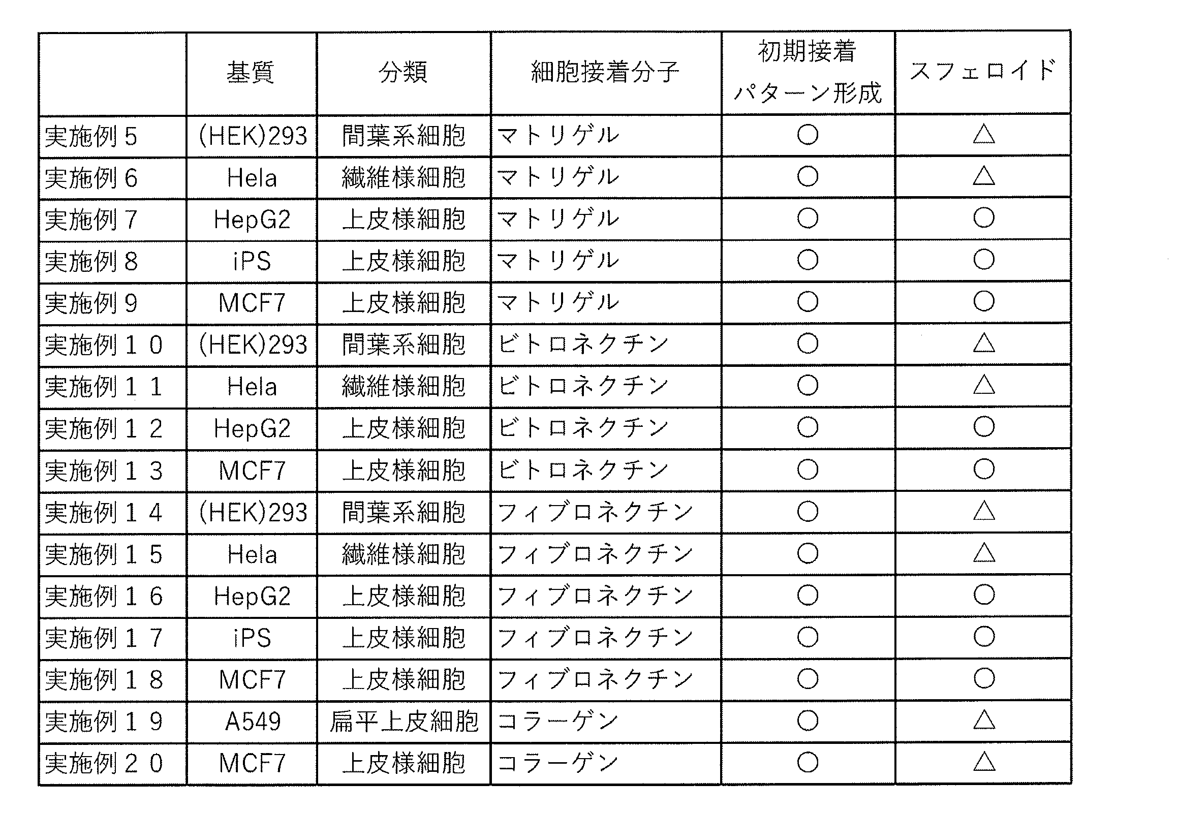
〔検証実験結果〕
各実施例1~4について、剥離前の細胞培養物の写真を図8に示す。図8(a)は実施例1、図8(b)は実施例2、図8(c)は実施例3、図8(d)は実施例4の剥離前の細胞培養物の写真である。また、剥離後の細胞培養物の写真を図9に示す。図9(a)は実施例1、図9(b)は実施例2、図9(c)は実施例3、図9(d)は実施例4の剥離後の細胞培養物の写真である。
図8、図9に見るように、いずれの実施例においても、細胞培養物(スフェロイド)が形成され、かつ、これを破壊することなく培養液中に浮遊させ、回収できることが分かった。
また、ドットの寸法に応じて、スフェロイドの大きさが制御可能であることも分かった。
各実施例1~4について、剥離前の細胞培養物の写真を図8に示す。図8(a)は実施例1、図8(b)は実施例2、図8(c)は実施例3、図8(d)は実施例4の剥離前の細胞培養物の写真である。また、剥離後の細胞培養物の写真を図9に示す。図9(a)は実施例1、図9(b)は実施例2、図9(c)は実施例3、図9(d)は実施例4の剥離後の細胞培養物の写真である。
図8、図9に見るように、いずれの実施例においても、細胞培養物(スフェロイド)が形成され、かつ、これを破壊することなく培養液中に浮遊させ、回収できることが分かった。
また、ドットの寸法に応じて、スフェロイドの大きさが制御可能であることも分かった。
また、実施例5~20について、図10~図13に、各実施例での写真を示す。初期接着性・パターン形成性、スフェロイド形成を評価し、その結果を上記表3及び図10~図13に併記した。
なお、スフェロイド形成の評価は、以下の基準に従った。
〇: 細胞凝集体が、3次元的に十分な厚みと大きさで球型とみなせる場合
△: 細胞凝集体が、3次元的にある程度の厚みと大きさを持つ場合
×: 細胞がほとんど凝集しておらず、2次元的に分散している場合
(厚みがある場合、顕微鏡観察時に透過光が減り、色が濃く見える。)
〇: 細胞凝集体が、3次元的に十分な厚みと大きさで球型とみなせる場合
△: 細胞凝集体が、3次元的にある程度の厚みと大きさを持つ場合
×: 細胞がほとんど凝集しておらず、2次元的に分散している場合
(厚みがある場合、顕微鏡観察時に透過光が減り、色が濃く見える。)
表3及び図10~図13に示す通り、様々な培養細胞及び細胞接着分子の組み合わせにおいて、細胞培養物(スフェロイド)が形成され、かつ、これを破壊することなく培養液中に浮遊させ、回収できることが分かった。
〔シール法〕
図14にシール法で作製した細胞接着分子20bのパターンを例示する。基材32は、平面状の石英基板にフッ素樹脂(サイトップCTX-809A、AGC社製)をスピンコートしたものを用いた。シール材50は紫外線硬化樹脂(DYMAX社製)を基材32にスピンコートし、ドットパターンのネガ型をマスクにして紫外線硬化した後、未硬化部分を除去することで形成した。図14(a)は、基材32の上に、孔50aが4つ形成されたシール材50が形成されたものである。スケールバーは10mmである。
図14にシール法で作製した細胞接着分子20bのパターンを例示する。基材32は、平面状の石英基板にフッ素樹脂(サイトップCTX-809A、AGC社製)をスピンコートしたものを用いた。シール材50は紫外線硬化樹脂(DYMAX社製)を基材32にスピンコートし、ドットパターンのネガ型をマスクにして紫外線硬化した後、未硬化部分を除去することで形成した。図14(a)は、基材32の上に、孔50aが4つ形成されたシール材50が形成されたものである。スケールバーは10mmである。
図14(b)は、シール材50を基材32から剥がした状態を示す。シール材50を基材32から剥がしても、シール材50の成分は基材32上に残らず、きれいに剥離させることができた。
図14(c)は、シール材50を基材32上の形成した状態で、細胞接着分子20bを塗布し、1時間定着した後、シール材50を剥離して得たパターン化された細胞接着分子20b(細胞接着分子領域)の写真である。直径1mm、厚み0.1mmの円筒状の細胞接着分子20bを得ることができた。基材32上の細胞接着分子20bは本発明に係る細胞培養足場である。また、図14(a)の基材32上に孔50aが形成されたシール材50が密着配置されたものは、本発明に係るスフェロイド形成用細胞培養キットである。
次にシール法で作製した細胞培養足場を使ってスフェロイドを作製した。
まず、図14に示した直径1mm(=1000μm)の孔50aが形成されたシール材50付き基材32をガス滅菌した。
次にシール材50上からマトリゲルを添加し(細胞接着分子の配置)、37℃でインキュベータ内で1時間定着させた。
まず、図14に示した直径1mm(=1000μm)の孔50aが形成されたシール材50付き基材32をガス滅菌した。
次にシール材50上からマトリゲルを添加し(細胞接着分子の配置)、37℃でインキュベータ内で1時間定着させた。
火炎滅菌したピンセットでシール材50を剥離し、直径1000μmの細胞接着分子(マトリゲル)ドットがパターン化された細胞培養足場を得た。
次に実施例5、10、14で用いた細胞(Hek293)を基材32上に播種した。そして、上記実施例と同様の培養方法(「(2-4)培養の手順」に記載方法)で培養した。
細胞播種後、5日目にピペッティングで基材32から剥離し、6日目に細胞をを観察した。
次に実施例5、10、14で用いた細胞(Hek293)を基材32上に播種した。そして、上記実施例と同様の培養方法(「(2-4)培養の手順」に記載方法)で培養した。
細胞播種後、5日目にピペッティングで基材32から剥離し、6日目に細胞をを観察した。
観察結果を図15に示す。細胞Hek293のスフェロイドを得ることができた。
本発明に係る細胞培養足場は、スフェロイド状体の細胞培養物を得るのに好適に利用できる。
9 外容器
10 鋳型
11 基板
12 レジスト
13 ヒーター
14 光源
15 フォトマスク
20 マイクロスタンプ
20b 細胞接着分子
20bh 厚み
21 ゴム管
22 離型剤
23 スタンプ材料
24 定温乾燥機
20a 凸部
32 基材
32a (撥水性)表面
41 培養液
42 細胞培養物
50 シール材
50a 孔
10 鋳型
11 基板
12 レジスト
13 ヒーター
14 光源
15 フォトマスク
20 マイクロスタンプ
20b 細胞接着分子
20bh 厚み
21 ゴム管
22 離型剤
23 スタンプ材料
24 定温乾燥機
20a 凸部
32 基材
32a (撥水性)表面
41 培養液
42 細胞培養物
50 シール材
50a 孔
Claims (10)
- フッ素樹脂による撥水性表面を有する基材と、前記基材の撥水性表面に形成された細胞接着分子とを備える、細胞培養足場。
- 前記細胞接着分子が細胞外マトリックスである、請求項1に記載の細胞培養足場。
- 前記細胞接着分子が、前記基材の撥水性表面にパターン状に形成されている、請求項1又は2に記載の細胞培養足場。
- 前記細胞接着分子は、直径100~1000μmのドット形状に形成されている、請求項1乃至3の何れか一の請求項に記載された細胞培養足場。
- 請求項1から4までのいずれかに記載の細胞培養足場を用いて、前記細胞接着分子表面で細胞を培養する工程を含む、細胞培養物の作製方法。
- 細胞培養開始から一定期間経過後、前記基材の撥水性表面と前記細胞接着分子の界面での接着力が低下することを利用して、自然に又は前記界面に刺激を与えて、細胞接着分子を剥離し、これを回収する工程を含む、請求項5に記載の細胞培養物の作製方法。
- 前記細胞が接着性細胞である、請求項5又は6に記載の細胞培養物の作製方法。
- フッ素樹脂による撥水性表面を有する基材に1つ以上の孔の開いたシール材を配置させる工程と、
前記シール材の上から細胞接着分子を配置する工程と、
前記シール材を剥離する工程を有する細胞培養足場の製造方法。 - フッ素樹脂による撥水性表面を有する基材に1つ以上の孔が形成されたシール材を密着配置させたスフェロイド形成用細胞培養キット。
- 前記孔は大きさの異なる孔が複数形成されたことを特徴とする請求項9に記載されたスフェロイド形成用細胞培養キット。
Priority Applications (3)
| Application Number | Priority Date | Filing Date | Title |
|---|---|---|---|
| JP2021530687A JPWO2021006242A1 (ja) | 2019-07-05 | 2020-07-06 | |
| US17/623,738 US20220251489A1 (en) | 2019-07-05 | 2020-07-06 | Cell culture scaffold, production method thereof, scaffold production kit, and production method of cell culture product |
| EP20837127.8A EP3995566A4 (en) | 2019-07-05 | 2020-07-06 | Cell culture scaffold, production method and scaffold production kit therefor, and cell culture creation method |
Applications Claiming Priority (2)
| Application Number | Priority Date | Filing Date | Title |
|---|---|---|---|
| JP2019-125709 | 2019-07-05 | ||
| JP2019125709 | 2019-07-05 |
Publications (1)
| Publication Number | Publication Date |
|---|---|
| WO2021006242A1 true WO2021006242A1 (ja) | 2021-01-14 |
Family
ID=74114221
Family Applications (1)
| Application Number | Title | Priority Date | Filing Date |
|---|---|---|---|
| PCT/JP2020/026399 WO2021006242A1 (ja) | 2019-07-05 | 2020-07-06 | 細胞培養足場、その製造方法と足場製造キット及び細胞培養物の作製方法 |
Country Status (4)
| Country | Link |
|---|---|
| US (1) | US20220251489A1 (ja) |
| EP (1) | EP3995566A4 (ja) |
| JP (1) | JPWO2021006242A1 (ja) |
| WO (1) | WO2021006242A1 (ja) |
Citations (4)
| Publication number | Priority date | Publication date | Assignee | Title |
|---|---|---|---|---|
| US5108926A (en) * | 1987-09-08 | 1992-04-28 | Board Of Regents, The University Of Texas System | Apparatus for the precise positioning of cells |
| JP2013099282A (ja) | 2011-11-08 | 2013-05-23 | Dainippon Printing Co Ltd | 細胞培養容器及び培養細胞回収方法 |
| WO2014112633A1 (ja) * | 2013-01-18 | 2014-07-24 | 東洋合成工業株式会社 | 細胞培養用基材及び細胞培養用基材の製造方法 |
| JP2016214210A (ja) | 2015-05-26 | 2016-12-22 | 住友電気工業株式会社 | 細胞培養担体及びこれを備える細胞シート |
Family Cites Families (3)
| Publication number | Priority date | Publication date | Assignee | Title |
|---|---|---|---|---|
| US20070218554A1 (en) * | 2004-04-26 | 2007-09-20 | Dai Nippon Printing Co., Ltd. | Cell Culture Patterning Substrate And Method For Manufacturing The Same |
| WO2010027081A1 (ja) * | 2008-09-08 | 2010-03-11 | 学校法人東京理科大学 | スフェロイド複合体およびスフェロイド含有ハイドロゲルならびにその製造方法 |
| JP5407344B2 (ja) * | 2009-01-13 | 2014-02-05 | 大日本印刷株式会社 | 生体組織の作製方法 |
-
2020
- 2020-07-06 EP EP20837127.8A patent/EP3995566A4/en active Pending
- 2020-07-06 JP JP2021530687A patent/JPWO2021006242A1/ja active Pending
- 2020-07-06 WO PCT/JP2020/026399 patent/WO2021006242A1/ja active Search and Examination
- 2020-07-06 US US17/623,738 patent/US20220251489A1/en not_active Abandoned
Patent Citations (4)
| Publication number | Priority date | Publication date | Assignee | Title |
|---|---|---|---|---|
| US5108926A (en) * | 1987-09-08 | 1992-04-28 | Board Of Regents, The University Of Texas System | Apparatus for the precise positioning of cells |
| JP2013099282A (ja) | 2011-11-08 | 2013-05-23 | Dainippon Printing Co Ltd | 細胞培養容器及び培養細胞回収方法 |
| WO2014112633A1 (ja) * | 2013-01-18 | 2014-07-24 | 東洋合成工業株式会社 | 細胞培養用基材及び細胞培養用基材の製造方法 |
| JP2016214210A (ja) | 2015-05-26 | 2016-12-22 | 住友電気工業株式会社 | 細胞培養担体及びこれを備える細胞シート |
Non-Patent Citations (5)
| Title |
|---|
| "HepG2: Cell Resource Center for Biomedical Research", INSTITUTE OF DEVELOPMENT, AGING AND CANCER, TOHOKU UNIVERSITY |
| KUSUNOKI, MASANOBU ET AL.: "Micro-patterning technique for capillary blood vessels on Polytetrafluoroethylene substrate", MEMOIRS OF THE FACULTY OF BIOLOGY-ORIENTECL SCIENCE AND TECHNOLOGY OF KINKI UNIVERSITY, vol. 25, 2010, pages 1 - 5, XP055783461 * |
| KUSUNOKI, MASANOBU ET AL.: "Nerve cell patterning using polytetrafluoroethylene and poly-D-lysine", THE TRANSACTIONS OF THE INSTITUTE OF ELECTRICAL ENGINEERS OF JAPAN C, vol. 129, no. 11, 2009, pages 2014 - 2018, XP055783450 * |
| See also references of EP3995566A4 |
| TAMURA: "Studies on apatite dot production methods for obtaining cell/spheroid arrays", JAPANESE SOCIETY FOR MEDICAL AND BIOLOGICAL ENGINEERING SYMPOSIUM 2013, 20 September 2013 (2013-09-20), pages 141 |
Also Published As
| Publication number | Publication date |
|---|---|
| US20220251489A1 (en) | 2022-08-11 |
| JPWO2021006242A1 (ja) | 2021-01-14 |
| EP3995566A1 (en) | 2022-05-11 |
| EP3995566A4 (en) | 2023-08-02 |
Similar Documents
| Publication | Publication Date | Title |
|---|---|---|
| Camelliti et al. | Micropatterned cell cultures on elastic membranes as an in vitro model of myocardium | |
| JP5853512B2 (ja) | 細胞培養容器とその製造方法 | |
| Jiao et al. | Thermoresponsive nanofabricated substratum for the engineering of three-dimensional tissues with layer-by-layer architectural control | |
| JP2020036621A (ja) | 細胞培養支持体、細胞培養装置、細胞培養キット、及び細胞シート | |
| JP4507845B2 (ja) | 細胞培養容器、及び培養細胞 | |
| US20080026460A1 (en) | Method for culturing stem cells | |
| Versaevel et al. | Micropatterning hydroxy-PAAm hydrogels and Sylgard 184 silicone elastomers with tunable elastic moduli | |
| JP5942387B2 (ja) | 細胞培養容器及び培養細胞回収方法 | |
| Pensabene et al. | Ultrathin polymer membranes with patterned, micrometric pores for organs-on-chips | |
| CN102465119A (zh) | 用于细胞图案化生长的基底、制备方法及其应用 | |
| WO2012124353A1 (ja) | 培養方法、成熟脂肪細胞群及び薬物スクリーニング方法 | |
| Chen et al. | Liver-lobule-mimicking patterning via dielectrophoresis and hydrogel photopolymerization | |
| KR101264243B1 (ko) | 미분화능이 우수한 배아줄기세포의 배양방법 및 이를 위한 배아줄기세포 배양기 | |
| JP2011155945A (ja) | 組織培養用培養器、及び三次元組織培養物の製造方法 | |
| JPWO2010134606A1 (ja) | 胚性幹細胞或いは人工多能性幹細胞の分化誘導方法 | |
| US9518249B2 (en) | Cell carrier, associated methods for making cell carrier and culturing cells using the same | |
| WO2021006242A1 (ja) | 細胞培養足場、その製造方法と足場製造キット及び細胞培養物の作製方法 | |
| JP4967520B2 (ja) | 細胞転写用部材 | |
| Shrirao et al. | Vacuum-assisted fluid flow in microchannels to pattern substrates and cells | |
| JP6060790B2 (ja) | 細胞培養用基材の製造方法 | |
| JP6326915B2 (ja) | 細胞培養基材 | |
| JP6248617B2 (ja) | 細胞シートの製造方法 | |
| JP6621245B2 (ja) | 制御された微細構造を含む三次元構造を有する人工組織の作製方法 | |
| JP6472601B2 (ja) | 細胞排除性を発現する溝構造 | |
| JP6041294B2 (ja) | 細胞培養基材、培養容器、及び細胞培養基材の製造方法 |
Legal Events
| Date | Code | Title | Description |
|---|---|---|---|
| 121 | Ep: the epo has been informed by wipo that ep was designated in this application |
Ref document number: 20837127 Country of ref document: EP Kind code of ref document: A1 |
|
| DPE1 | Request for preliminary examination filed after expiration of 19th month from priority date (pct application filed from 20040101) | ||
| ENP | Entry into the national phase |
Ref document number: 2021530687 Country of ref document: JP Kind code of ref document: A |
|
| ENP | Entry into the national phase |
Ref document number: 2020837127 Country of ref document: EP Effective date: 20220207 |