WO2021006113A1 - 指先用医療用具 - Google Patents
指先用医療用具 Download PDFInfo
- Publication number
- WO2021006113A1 WO2021006113A1 PCT/JP2020/025643 JP2020025643W WO2021006113A1 WO 2021006113 A1 WO2021006113 A1 WO 2021006113A1 JP 2020025643 W JP2020025643 W JP 2020025643W WO 2021006113 A1 WO2021006113 A1 WO 2021006113A1
- Authority
- WO
- WIPO (PCT)
- Prior art keywords
- medical device
- fingertip
- finger
- fluorescence
- fingertips
- Prior art date
- Legal status (The legal status is an assumption and is not a legal conclusion. Google has not performed a legal analysis and makes no representation as to the accuracy of the status listed.)
- Ceased
Links
Images





Classifications
-
- A—HUMAN NECESSITIES
- A61—MEDICAL OR VETERINARY SCIENCE; HYGIENE
- A61B—DIAGNOSIS; SURGERY; IDENTIFICATION
- A61B90/00—Instruments, implements or accessories specially adapted for surgery or diagnosis and not covered by any of the groups A61B1/00 - A61B50/00, e.g. for luxation treatment or for protecting wound edges
- A61B90/30—Devices for illuminating a surgical field, the devices having an interrelation with other surgical devices or with a surgical procedure
-
- A—HUMAN NECESSITIES
- A41—WEARING APPAREL
- A41D—OUTERWEAR; PROTECTIVE GARMENTS; ACCESSORIES
- A41D19/00—Gloves
- A41D19/015—Protective gloves
- A41D19/0157—Protective gloves with luminous or reflective means
-
- A—HUMAN NECESSITIES
- A61—MEDICAL OR VETERINARY SCIENCE; HYGIENE
- A61B—DIAGNOSIS; SURGERY; IDENTIFICATION
- A61B5/00—Measuring for diagnostic purposes; Identification of persons
- A61B5/0059—Measuring for diagnostic purposes; Identification of persons using light, e.g. diagnosis by transillumination, diascopy, fluorescence
- A61B5/0071—Measuring for diagnostic purposes; Identification of persons using light, e.g. diagnosis by transillumination, diascopy, fluorescence by measuring fluorescence emission
-
- A—HUMAN NECESSITIES
- A61—MEDICAL OR VETERINARY SCIENCE; HYGIENE
- A61B—DIAGNOSIS; SURGERY; IDENTIFICATION
- A61B5/00—Measuring for diagnostic purposes; Identification of persons
- A61B5/0059—Measuring for diagnostic purposes; Identification of persons using light, e.g. diagnosis by transillumination, diascopy, fluorescence
- A61B5/0082—Measuring for diagnostic purposes; Identification of persons using light, e.g. diagnosis by transillumination, diascopy, fluorescence adapted for particular medical purposes
- A61B5/0084—Measuring for diagnostic purposes; Identification of persons using light, e.g. diagnosis by transillumination, diascopy, fluorescence adapted for particular medical purposes for introduction into the body, e.g. by catheters
-
- A—HUMAN NECESSITIES
- A61—MEDICAL OR VETERINARY SCIENCE; HYGIENE
- A61B—DIAGNOSIS; SURGERY; IDENTIFICATION
- A61B5/00—Measuring for diagnostic purposes; Identification of persons
- A61B5/0059—Measuring for diagnostic purposes; Identification of persons using light, e.g. diagnosis by transillumination, diascopy, fluorescence
- A61B5/0082—Measuring for diagnostic purposes; Identification of persons using light, e.g. diagnosis by transillumination, diascopy, fluorescence adapted for particular medical purposes
- A61B5/0084—Measuring for diagnostic purposes; Identification of persons using light, e.g. diagnosis by transillumination, diascopy, fluorescence adapted for particular medical purposes for introduction into the body, e.g. by catheters
- A61B5/0086—Measuring for diagnostic purposes; Identification of persons using light, e.g. diagnosis by transillumination, diascopy, fluorescence adapted for particular medical purposes for introduction into the body, e.g. by catheters using infrared radiation
-
- A—HUMAN NECESSITIES
- A61—MEDICAL OR VETERINARY SCIENCE; HYGIENE
- A61B—DIAGNOSIS; SURGERY; IDENTIFICATION
- A61B5/00—Measuring for diagnostic purposes; Identification of persons
- A61B5/42—Detecting, measuring or recording for evaluating the gastrointestinal, the endocrine or the exocrine systems
- A61B5/4222—Evaluating particular parts, e.g. particular organs
- A61B5/4255—Intestines, colon or appendix
-
- A—HUMAN NECESSITIES
- A61—MEDICAL OR VETERINARY SCIENCE; HYGIENE
- A61B—DIAGNOSIS; SURGERY; IDENTIFICATION
- A61B5/00—Measuring for diagnostic purposes; Identification of persons
- A61B5/68—Arrangements of detecting, measuring or recording means, e.g. sensors, in relation to patient
- A61B5/6801—Arrangements of detecting, measuring or recording means, e.g. sensors, in relation to patient specially adapted to be attached to or worn on the body surface
- A61B5/6813—Specially adapted to be attached to a specific body part
- A61B5/6825—Hand
- A61B5/6826—Finger
-
- A—HUMAN NECESSITIES
- A61—MEDICAL OR VETERINARY SCIENCE; HYGIENE
- A61B—DIAGNOSIS; SURGERY; IDENTIFICATION
- A61B90/00—Instruments, implements or accessories specially adapted for surgery or diagnosis and not covered by any of the groups A61B1/00 - A61B50/00, e.g. for luxation treatment or for protecting wound edges
-
- A—HUMAN NECESSITIES
- A61—MEDICAL OR VETERINARY SCIENCE; HYGIENE
- A61B—DIAGNOSIS; SURGERY; IDENTIFICATION
- A61B90/00—Instruments, implements or accessories specially adapted for surgery or diagnosis and not covered by any of the groups A61B1/00 - A61B50/00, e.g. for luxation treatment or for protecting wound edges
- A61B90/36—Image-producing devices or illumination devices not otherwise provided for
-
- A—HUMAN NECESSITIES
- A41—WEARING APPAREL
- A41D—OUTERWEAR; PROTECTIVE GARMENTS; ACCESSORIES
- A41D19/00—Gloves
- A41D19/0013—Gloves with openings, e.g. for the nails or for exposing jewellery
-
- A—HUMAN NECESSITIES
- A41—WEARING APPAREL
- A41D—OUTERWEAR; PROTECTIVE GARMENTS; ACCESSORIES
- A41D19/00—Gloves
- A41D19/0024—Gloves with accessories
- A41D19/0027—Measuring instruments, e.g. watch, thermometer
-
- A—HUMAN NECESSITIES
- A41—WEARING APPAREL
- A41D—OUTERWEAR; PROTECTIVE GARMENTS; ACCESSORIES
- A41D19/00—Gloves
- A41D19/0055—Plastic or rubber gloves
-
- A—HUMAN NECESSITIES
- A61—MEDICAL OR VETERINARY SCIENCE; HYGIENE
- A61B—DIAGNOSIS; SURGERY; IDENTIFICATION
- A61B17/00—Surgical instruments, devices or methods
- A61B2017/0042—Surgical instruments, devices or methods with special provisions for gripping
- A61B2017/00438—Surgical instruments, devices or methods with special provisions for gripping connectable to a finger
-
- A—HUMAN NECESSITIES
- A61—MEDICAL OR VETERINARY SCIENCE; HYGIENE
- A61B—DIAGNOSIS; SURGERY; IDENTIFICATION
- A61B90/00—Instruments, implements or accessories specially adapted for surgery or diagnosis and not covered by any of the groups A61B1/00 - A61B50/00, e.g. for luxation treatment or for protecting wound edges
- A61B90/30—Devices for illuminating a surgical field, the devices having an interrelation with other surgical devices or with a surgical procedure
- A61B2090/304—Devices for illuminating a surgical field, the devices having an interrelation with other surgical devices or with a surgical procedure using chemi-luminescent materials
-
- A—HUMAN NECESSITIES
- A61—MEDICAL OR VETERINARY SCIENCE; HYGIENE
- A61B—DIAGNOSIS; SURGERY; IDENTIFICATION
- A61B90/00—Instruments, implements or accessories specially adapted for surgery or diagnosis and not covered by any of the groups A61B1/00 - A61B50/00, e.g. for luxation treatment or for protecting wound edges
- A61B90/30—Devices for illuminating a surgical field, the devices having an interrelation with other surgical devices or with a surgical procedure
- A61B2090/309—Devices for illuminating a surgical field, the devices having an interrelation with other surgical devices or with a surgical procedure using white LEDs
-
- A—HUMAN NECESSITIES
- A61—MEDICAL OR VETERINARY SCIENCE; HYGIENE
- A61B—DIAGNOSIS; SURGERY; IDENTIFICATION
- A61B42/00—Surgical gloves; Finger-stalls specially adapted for surgery; Devices for handling or treatment thereof
- A61B42/10—Surgical gloves
-
- A—HUMAN NECESSITIES
- A61—MEDICAL OR VETERINARY SCIENCE; HYGIENE
- A61B—DIAGNOSIS; SURGERY; IDENTIFICATION
- A61B42/00—Surgical gloves; Finger-stalls specially adapted for surgery; Devices for handling or treatment thereof
- A61B42/20—Finger-stalls specially adapted for surgery
Definitions
- the present invention relates to a medical device for fingertips that has a resin layer that emits red or near-infrared fluorescence, and the resin layer is adhered to a fingertip.
- An endoscope is used to diagnose cancers that have developed in the mucous membranes of tubular human tissues such as the rectum. Palpation, in which the operator's finger is inserted into the body, is also used for diagnosis. Therefore, it has been proposed to attach an imaging device to the tip of the finger cot and to provide the finger cot with a window opening for palpation (Patent Document 1).
- the present invention makes it possible to identify the position of the affected area from the serosa side of the tubular human tissue when the doctor identifies the position of the affected area by palpating the mucous membrane of the tubular human tissue such as the rectum. Is the subject.
- the present inventor adheres a resin layer that emits red fluorescence or near-infrared fluorescence to the tip of a finger to be palpated, and observes the fluorescence emitted by the resin layer from the serosa side to the mucosal side by palpation.
- the present invention was completed with the idea that the position of the affected area identified in 1 can be specified from the serosa side.
- the present invention provides a medical device for fingertips that has a resin layer that emits red fluorescence or near-infrared fluorescence and is adhered to the fingertips.
- a resin layer that emits red fluorescence or near-infrared fluorescence can be adhered to the fingertips. Therefore, by observing the fluorescence emitted by the resin layer, the affected area identified by palpation on the mucosal side It is possible to specify the position of the resin from the serosal side. Therefore, when surgically excising the affected area identified by palpation on the mucosal side, the margin of the excision range required because the location of the affected area cannot be accurately determined should be significantly reduced or eliminated. And the excision range can be minimized. Therefore, for example, it becomes possible to preserve the anus that was previously unnecessarily excised, and the burden on the patient is reduced.
- FIG. 1 is a front view of the fingertip medical device 1A of the finger cot-shaped embodiment.
- FIG. 2A is an explanatory diagram of the position of the affected part in the body when the affected part is in the rectum.
- FIG. 2B is an explanatory diagram of a method of identifying the position of the affected portion in the rectum with the fingertip medical device 1A of the embodiment.
- FIG. 3 is a perspective view of the fingertip medical device 1B of the embodiment.
- FIG. 4 is a perspective view of the fingertip medical device 1C of the embodiment.
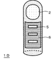
- FIG. 5 is a perspective view of the fingertip medical device 1D of the embodiment.
- FIG. 6 is a perspective view of the fingertip medical device 1E of the embodiment.
- FIG. 1 is a front view of the fingertip medical device 1A of the finger cot-shaped embodiment.
- FIG. 2A is an explanatory diagram of the position of the affected part in the body when the affected part is in the rectum.
- FIG. 2B
- FIG. 7 is a perspective view of the fingertip medical device 1F of the embodiment.
- FIG. 8 is a perspective view of the fingertip medical device 1G of the embodiment.
- FIG. 9A is a perspective view of the fingertip medical device 1H of the embodiment.
- FIG. 9B is a perspective view of the fingertip medical device 1H in the state of being attached to the glove.
- FIG. 10A is a perspective view of the fingertip medical device 1I of the embodiment.
- FIG. 10B is a perspective view of the fingertip medical device 1I in the state of being attached to the glove.
- FIG. 11A is an image of the fingertip medical device 1A taken by a digital color camera under white illumination.
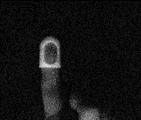
- FIG. 11B is an image of the front surface of the silicone sheet when the fingertip medical device 1A of the embodiment is placed behind the silicone sheet and the front surface of the silicone sheet is photographed by a digital color camera under white illumination.
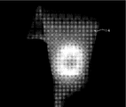
- FIG. 11C shows an image of the front surface of the silicone sheet when the fingertip medical device 1A of the embodiment is placed behind the silicone sheet, the front surface of the silicone sheet is irradiated with excitation light, and the front surface thereof is photographed by a near-infrared color system. is there.
- FIG. 1 is a front view of a finger cot-shaped medical device 1A for fingertips according to an embodiment of the present invention, and a broken line represents a hand having the finger cot-shaped medical device 1A for fingertips attached to a finger.
- the medical device for fingertips of the present invention has a resin layer that emits red fluorescence or near-infrared fluorescence adhered around the fingertips, particularly the pad of the finger or the pad of the finger.
- the fingertip medical device 1A has a length that covers the first joint of the finger from the fingertip when worn on the finger, and also has a fenestration portion that exposes at least the central portion of the finger pad. Has 2. The presence of the fenestration 2 allows the operator to easily perform palpation using the pad of the finger exposed from the fenestration 2.
- the size of the window opening portion 2 is preferably 5 to 15 mm in width w1 and 5 to 20 mm in length h1 from the viewpoint of enabling palpation.
- the resin layer of the fingertip medical device 1A fluoresces.
- the fenestration part 2 is dark and the circumference of the fenestration part 2 is observed brightly in a ring shape, and the position of the fenestration part, that is, the position of the affected part can be specified, but the affected part is more accurately observed.
- the width w1 of the window opening portion 2 is 10 to 15 mm and the length h1 is 10 to 20 mm from the viewpoint of making it possible to specify the position of.
- the size of the window opening portion 2 is too small, the light emitting portion observed from the serosa side does not form a ring shape, and the portion corresponding to the window opening portion 2 also appears to emit light. It becomes difficult to accurately identify the position, and conversely, if it is too large, it becomes difficult to identify where the affected area is in the darkly observed part.
- the fingertip medical device 1A is made of a resin that emits red fluorescence or near-infrared fluorescence.
- a resin that emits red fluorescence or near-infrared fluorescence for example, a flexible resin in which a fluorescent dye is kneaded can be used.
- the flexible resin a polyurethane, polypropylene, polyethylene, polyvinyl chloride, polyamide, polyamide elastomer or the like mixed with a curing agent, if necessary, can be used. It is preferable that the shore hardness after curing is 30A to 70A. Further, by using a resin having an elongation at the time of cutting of 300% or more, the fit feeling when the finger cot-shaped medical device for fingertips 1A is fitted to the fingertips is improved.
- the preferable thickness of the resin layer forming the finger cot shape is determined according to the emission intensity of the resin layer containing the fluorescent dye, and therefore varies depending on the type and concentration of the fluorescent dye, but usually the thickness is 0.1 to 2 mm. preferable.
- the fluorescent dye to be kneaded into the flexible resin is preferably one that fluoresces in the red to near infrared wavelength range of 600 to 1400 nm, preferably in the red light or near infrared light wavelength range of 700 to 1100 nm.
- Light in such a wavelength range is highly permeable to human tissues such as skin, fat, and muscle, and can reach the serosal surface from the mucous membrane of tubular human tissues such as the rectum.
- Examples of the fluorescent dye that emits fluorescence in the above-mentioned wavelength range include riboflavin, thiamine, NADH (nicotinamide adenine dinucleotide), indocyanine green (ICG), and the azo-boron complex compound described in JP-A-2011-162445, WO 2016/132596. Examples thereof include dyes having a fused ring structure described in Japanese Patent Publication No.
- the preferable concentration of the fluorescent dye in the resin that emits near-infrared fluorescence is determined according to the type of the fluorescent dye and the resin used as the binder, and is usually preferably 0.001 to 1% by mass.
- the fluorescent dye is kneaded into the resin using a biaxial kneader. After that, it may be formed into a finger cot shape by extrusion molding or injection molding.
- a contrast agent such as barium sulfate may be added to the fluorescent resin, if necessary.
- the medical device 1A for fingertips As a method of using the medical device 1A for fingertips, for example, when the position X of the rectal cancer shown in FIG. 2A can be identified from the serosa side, first, the operator's hand, preferably the operator wearing surgical gloves. As shown in FIG. 1, a finger cot-shaped medical device for fingertips 1A is fitted to the fingers of the hand. In this case, the opening portion 2 is positioned on the pad of the finger.
- a finger fitted with a finger cot-shaped medical device for fingertips 1A is inserted into the rectum from the anus, the rectum is palpated to locate the cancer, and the finger is exposed from the fenestration 2. Hold down the cancer with the pad of your finger. Then, the serosa side of the rectum is irradiated with excitation light for emitting red fluorescence or near-infrared fluorescence to the resin forming the fingertip medical device 1A, and the fluorescence emitted by the fingertip medical device 1A is emitted from the serosa side. Observe.
- the serosa of the rectum may be exposed by laparotomy and the excitation light may be irradiated there.
- a surgical endoscope is inserted through a hole made in the abdominal wall and irradiated from the serosa side. You may.
- the wavelength of the excitation light is shorter than the wavelength of fluorescence, but the wavelength range of the excitation light that emits red fluorescence or near-infrared fluorescence is also highly transparent to human tissue, and the excitation light irradiated to the serous membrane side is the tissue of the rectum or It is absorbed by the fingertip medical device 1A on the mucosal side with almost no inhibition of absorption by blood, and the resin layer of the fingertip medical device 1A emits red fluorescence or near-infrared fluorescence.
- the fluorescence when the fluorescence is red, it is observed with the naked eye, when the fluorescence is near infrared, it is observed through a known infrared visual conversion glass, or the rectum is photographed from the serosa side, and the near infrared is imaged.
- the ring-shaped light emission by the fingertip medical device 1A can be easily observed from the serosa side, and further, the dark part due to the fenestration 2 inside the ring-shaped light emitting part is the development of cancer. It can be specified as a position. If the position of the cancer can be identified from the serosal side in this way, a mark can be made with an electric knife, and the mark can be used as a guide when excising the affected area.
- the application scene of the medical device for fingertips 1A of the present invention is not limited to specifying the position of the affected part within the range where the finger is inserted from the outside of the human body as in the rectum described above.
- a finger equipped with a fingertip medical device 1A is inserted into a hole made in the abdominal wall for insertion of a laparoscope or a surgical instrument, and further inserted into the gastric cavity through a hole made in the stomach wall to insert the affected part in the gastric mucosa. It can also be used to specify the position of the gastric serosa.
- the position of the affected area can also be specified by the light emission of the fluorescent dye-containing resin attached to the clip by sandwiching the mucous membrane of the affected area with a metal clip described in Japanese Patent No. 1661096 and observing from the serosa side.
- a metal clip described in Japanese Patent No. 1661096 and observing from the serosa side.
- the metal clip will hit the scalpel during excision of the affected area and the scalpel will be damaged.
- the medical device for fingertips of the present invention even if the medical device for fingertips comes off from the operator's finger in the living body and the scalpel hits the medical device for fingertips when excising the affected part, the scalpel is damaged. There is no fear.
- the medical device for fingertips of the present invention can take various aspects.
- the fingertip medical device 1B shown in FIG. 3 has a take-out thread 3 attached to the end of the fingertip medical device 1A shown in FIG. 1 by adhesion or welding. Since the extraction thread 3 is attached to the fingertip medical device 1B, even if the fingertip medical device 1B comes off from the fingertip in the body, the fingertip medical device 1B can be easily inserted into the body by picking and pulling the extraction thread 3. Can be taken out from.
- the fingertip medical device 1C shown in FIG. 4 has a length of the fingertip medical device 1A shown in FIG. 1 so as to cover the second joint from the fingertip, and is below the fenestration portion 2 (that is, that is).
- Scales 4 are provided at predetermined intervals with an infrared or near-infrared light opaque resin on the finger insertion opening side).
- the scale was punched out in a scale shape instead of being formed of an infrared or near infrared light opaque resin.
- Infrared or near-infrared light impervious by attaching an infrared or near-infrared light opaque resin film 6 having holes 5 to a medical device main body 1, printing an infrared or near-infrared light opaque resin layer, or the like. It is provided with a permeable resin layer.
- the fingertip medical device 1D Since a resin that emits infrared or near-infrared fluorescence is exposed from this hole 5, when the fingertip medical device 1D is observed from the serous membrane side by irradiating with excitation light, the fingertip medical device fitted to the finger is used.
- the window opening portion 2 On the fingertip side of the tool 1D, the window opening portion 2 can be observed as a dark portion in the finger cot type light emitting region, and a scale that emits light in the dark portion region can be observed below the window opening portion.
- the fingertip medical device 1E shown in FIG. 6 has a finger cot shape having a window opening 2 similar to the fingertip medical device 1C shown in FIG. 4, and covers from the fingertip to the second joint. It has a length to be used.
- the finger cot shape itself is made of a resin 15 that does not contain a fluorescent dye that emits red light fluorescence or near infrared fluorescence.
- a ring-shaped resin layer 8 is formed around the window opening portion 2 by applying a paint containing a fluorescent dye that emits red fluorescence or near-infrared fluorescence.
- a scale 4 is formed on the lower side of the window opening portion 2 by a paint containing a fluorescent dye that emits red fluorescence or near-infrared fluorescence.
- the fingertip medical device 1E can be used in the same manner as the fingertip medical device 1C shown in FIG.
- the medical device for fingertips of the present invention is a finger cot type having a window opening portion
- the medical device for fingertips is formed of a resin that emits red fluorescence or near-infrared fluorescence.
- the circumference of the window opening may be formed of a resin that emits red fluorescence or near-infrared fluorescence. Therefore, the entire finger cot shape may be formed of this resin as in the fingertip medical device 1A shown in FIG. 1, and the window opening portion 2 may be formed as in the fingertip medical device 1E shown in FIG.
- a resin layer 8 that emits red fluorescence or near-infrared fluorescence may be formed around the coating layer.
- the fingertip medical device 1F shown in FIG. 7 has a glove shape, and has a ring-shaped printing layer 8 formed of a resin that emits red or near-infrared fluorescence on the pad of the index finger of the glove 7. ing.
- the ring-shaped printing layer 8 is formed so as to surround the central portion of the pad of the finger.
- the position of the affected area is specified by palpation with the fingertip having the ring-shaped printing layer 8 of the hand on which the fingertip medical device 1F is fitted. Then, excitation light is irradiated from the serosa side to cause the ring-shaped printing layer 8 to emit red or near-infrared fluorescence, and the fluorescence is observed from the serosa side in the same manner as in the fingertip medical device 1A shown in FIG.
- the affected area can be accurately identified as a dark area inside the ring-shaped light emitting area formed by the printing layer 8.
- the fingertip medical device 1G shown in FIG. 8 replaces the ring-shaped printing layer 8 formed of a resin that emits red fluorescence or near-infrared fluorescence in the glove-shaped fingertip medical device 1F shown in FIG. A circular printing layer 9 made of the same resin is provided.
- the affected part can be accurately identified as a circular light emitting part by observing the fluorescent light emitting part from the serosa side as in the fingertip medical device 1A shown in FIG. ..
- the fingertip medical device 1H shown in FIG. 9A is formed on one side of a ring-shaped resin layer 10 formed of a resin that emits red fluorescence or near-infrared fluorescence, similar to the ring-shaped printing layer 8 shown in FIG.
- This is a seal-shaped medical device for fingertips provided with an adhesive layer and the adhesive layer attached on the release film 11.
- the resin layer 10 of the seal-shaped medical device for fingertips 1H preferably has a size that can be attached to the inside of the finger pad. Therefore, the fingertip medical device 1H is peeled off from the release film 11, and as shown in FIG. 9B, the ring-shaped resin layer 10 is attached to the surgical glove 12, so that the glove-shaped fingertip medical treatment shown in FIG. 7 is attached. A configuration substantially similar to that of the tool 1F can be obtained. According to the fingertip medical device 1H, the fingertip medical device of the present invention can be constructed at a lower cost by using the surgical gloves 12 that are used on a daily basis.
- the ring-shaped resin layer 10 may be directly attached to the pad of the finger, and the surgical gloves 12 may be worn on the ring-shaped resin layer 10. This makes it possible to eliminate the possibility that the ring-shaped resin layer 10 will come off into the body during palpation.
- the fingertip medical device 1I shown in FIG. 10A is a seal-shaped fingertip medical device in which the ring-shaped resin layer 10 is formed on the circular resin layer 13 in the fingertip medical device 1H shown in FIG. 9A.
- the fingertip medical device 1I is also peeled off from the release film 11, and a circular resin layer 13 is attached to the surgical glove 12 as shown in FIG. 10B to obtain the glove-shaped fingertip medical device 1G shown in FIG.
- a substantially similar configuration can be obtained.
- a circular resin layer 13 is directly attached to the pad of the finger, a surgical glove 12 is worn over the circular resin layer 13, and the circular resin layer 13 is peeled off into the body. The fear may be eliminated.
- the fingertip medical device of the present invention has a sticker shape like the above-mentioned fingertip medical device 1H and 1I, in order to prevent palpation with the fingertip to which the sticker-shaped fingertip medical device is attached, the palpation is not hindered.
- the resin layers 10 and 13 to be attached to the finger have the same thinness and flexibility as surgical gloves. Therefore, the thickness of the resin layer to be attached to the finger is 0.1 to 0.3 mm, and the tensile force at the time of cutting is 9.0 N or more, similar to the physical characteristics of surgical gloves specified in JIS T9107. It is preferable that the elongation at cutting is 600% or more and the tensile force at 300% elongation is 3.0 N or less.
- the take-out thread 3 may be provided on the finger cot-shaped medical devices 1C and 1D shown in FIGS. 4 and 5.
- a dye having a condensed ring structure described in WO2016 / 132596 is kneaded with ABS resin to produce a finger cot type medical device 1A for fingertips having a thickness of 2 mm and shown in FIG. 1, and the medical device 1A for fingertips is manufactured. I put it on my finger. An image of a fingertip medical device 1A fitted on a finger taken with white illumination is shown in FIG. 11A.
- the fingertip medical device fitted to the finger was placed behind the silicone sheet (thickness 3 mm) 14 that imitated human tissue, and was photographed with a digital color camera from the front of the silicone sheet 14 under white lighting. This image is shown in FIG. 11B.
- excitation light (wavelength 740 to 760 nm) was irradiated from the front surface of the silicone sheet 14, and the front surface was photographed with a near infrared color camera system (Mizuho Co., Ltd.).
- This image is shown in FIG. 11C.
- a dark portion corresponding to the window opening portion 2 could be observed inside the finger cot type light emitting portion. Therefore, it can be seen that the position of the affected part can be specified from the serosa side by pressing the affected part on the mucosal side of the body cavity with the pad of the finger exposed from the window opening portion 2 of the fingertip medical device 1A and irradiating with excitation light.
Landscapes
- Health & Medical Sciences (AREA)
- Life Sciences & Earth Sciences (AREA)
- Surgery (AREA)
- Engineering & Computer Science (AREA)
- General Health & Medical Sciences (AREA)
- Public Health (AREA)
- Biomedical Technology (AREA)
- Heart & Thoracic Surgery (AREA)
- Medical Informatics (AREA)
- Molecular Biology (AREA)
- Veterinary Medicine (AREA)
- Animal Behavior & Ethology (AREA)
- Pathology (AREA)
- Physics & Mathematics (AREA)
- Biophysics (AREA)
- Nuclear Medicine, Radiotherapy & Molecular Imaging (AREA)
- Oral & Maxillofacial Surgery (AREA)
- Textile Engineering (AREA)
- Endocrinology (AREA)
- Gastroenterology & Hepatology (AREA)
- Physiology (AREA)
- Medicines Containing Antibodies Or Antigens For Use As Internal Diagnostic Agents (AREA)
- Surgical Instruments (AREA)
- Endoscopes (AREA)
Priority Applications (2)
| Application Number | Priority Date | Filing Date | Title |
|---|---|---|---|
| JP2021530623A JP7426731B2 (ja) | 2019-07-09 | 2020-06-30 | 指先用医療用具 |
| US17/421,457 US12076104B2 (en) | 2019-07-09 | 2020-06-30 | Medical tool for fingertip |
Applications Claiming Priority (2)
| Application Number | Priority Date | Filing Date | Title |
|---|---|---|---|
| JP2019-127358 | 2019-07-09 | ||
| JP2019127358A JP6675662B1 (ja) | 2019-07-09 | 2019-07-09 | 医療用具 |
Publications (1)
| Publication Number | Publication Date |
|---|---|
| WO2021006113A1 true WO2021006113A1 (ja) | 2021-01-14 |
Family
ID=70001004
Family Applications (1)
| Application Number | Title | Priority Date | Filing Date |
|---|---|---|---|
| PCT/JP2020/025643 Ceased WO2021006113A1 (ja) | 2019-07-09 | 2020-06-30 | 指先用医療用具 |
Country Status (3)
| Country | Link |
|---|---|
| US (1) | US12076104B2 (https=) |
| JP (2) | JP6675662B1 (https=) |
| WO (1) | WO2021006113A1 (https=) |
Families Citing this family (2)
| Publication number | Priority date | Publication date | Assignee | Title |
|---|---|---|---|---|
| JP6675662B1 (ja) | 2019-07-09 | 2020-04-01 | 国立大学法人高知大学 | 医療用具 |
| US11872355B2 (en) * | 2020-09-04 | 2024-01-16 | Covidien Lp | Medical device for detecting fluid parameters using fluorescent probes |
Citations (6)
| Publication number | Priority date | Publication date | Assignee | Title |
|---|---|---|---|---|
| JP2008038306A (ja) * | 2006-08-09 | 2008-02-21 | Joyo Machine Co Ltd | 視認性を向上させた作業用手袋 |
| JP2015126885A (ja) * | 2014-12-26 | 2015-07-09 | 国立大学法人高知大学 | 近赤外蛍光を発する医療具及び医療具位置確認システム |
| JP2016192997A (ja) * | 2015-03-31 | 2016-11-17 | Dic株式会社 | 成形体 |
| JP2017104147A (ja) * | 2015-12-07 | 2017-06-15 | 株式会社システック | 手術具に付ける蛍光体マーカー付設具、これを使用した手術具の体内残置検出方法、及び手術具の体内残置検出装置 |
| WO2017208596A1 (ja) * | 2016-05-31 | 2017-12-07 | コニカミノルタ株式会社 | 外科用手術器具 |
| WO2018123300A1 (ja) * | 2016-12-26 | 2018-07-05 | 公立大学法人横浜市立大学 | 蛍光性樹脂組成物、成形体及び医療用機器並びに蛍光性樹脂組成物の製造方法 |
Family Cites Families (7)
| Publication number | Priority date | Publication date | Assignee | Title |
|---|---|---|---|---|
| JPH11200121A (ja) * | 1998-01-13 | 1999-07-27 | Taisei Corp | 作業用手袋 |
| JP2002291746A (ja) | 2001-03-29 | 2002-10-08 | Fuji Photo Optical Co Ltd | 体腔内診断装置 |
| JP2008161337A (ja) * | 2006-12-27 | 2008-07-17 | Norikatsu Mitsuyoshi | 衛生材料 |
| JP5522447B2 (ja) | 2010-02-04 | 2014-06-18 | 国立大学法人高知大学 | アゾ−ホウ素錯体化合物およびその製造方法 |
| JP6161096B2 (ja) | 2014-05-29 | 2017-07-12 | 国立大学法人高知大学 | 生体圧迫クリップ |
| JP6255529B2 (ja) | 2015-02-18 | 2017-12-27 | Dic株式会社 | 樹脂組成物及びその製造方法、並びに成形体 |
| JP6675662B1 (ja) | 2019-07-09 | 2020-04-01 | 国立大学法人高知大学 | 医療用具 |
-
2019
- 2019-07-09 JP JP2019127358A patent/JP6675662B1/ja active Active
-
2020
- 2020-06-30 WO PCT/JP2020/025643 patent/WO2021006113A1/ja not_active Ceased
- 2020-06-30 US US17/421,457 patent/US12076104B2/en active Active
- 2020-06-30 JP JP2021530623A patent/JP7426731B2/ja active Active
Patent Citations (6)
| Publication number | Priority date | Publication date | Assignee | Title |
|---|---|---|---|---|
| JP2008038306A (ja) * | 2006-08-09 | 2008-02-21 | Joyo Machine Co Ltd | 視認性を向上させた作業用手袋 |
| JP2015126885A (ja) * | 2014-12-26 | 2015-07-09 | 国立大学法人高知大学 | 近赤外蛍光を発する医療具及び医療具位置確認システム |
| JP2016192997A (ja) * | 2015-03-31 | 2016-11-17 | Dic株式会社 | 成形体 |
| JP2017104147A (ja) * | 2015-12-07 | 2017-06-15 | 株式会社システック | 手術具に付ける蛍光体マーカー付設具、これを使用した手術具の体内残置検出方法、及び手術具の体内残置検出装置 |
| WO2017208596A1 (ja) * | 2016-05-31 | 2017-12-07 | コニカミノルタ株式会社 | 外科用手術器具 |
| WO2018123300A1 (ja) * | 2016-12-26 | 2018-07-05 | 公立大学法人横浜市立大学 | 蛍光性樹脂組成物、成形体及び医療用機器並びに蛍光性樹脂組成物の製造方法 |
Also Published As
| Publication number | Publication date |
|---|---|
| JP7426731B2 (ja) | 2024-02-02 |
| JPWO2021006113A1 (https=) | 2021-01-14 |
| JP6675662B1 (ja) | 2020-04-01 |
| US12076104B2 (en) | 2024-09-03 |
| US20220079697A1 (en) | 2022-03-17 |
| JP2021010661A (ja) | 2021-02-04 |
Similar Documents
| Publication | Publication Date | Title |
|---|---|---|
| JP4578817B2 (ja) | 外科手術用病変部同定システム | |
| JP6161096B2 (ja) | 生体圧迫クリップ | |
| EP3585319B1 (en) | Deployment catheter comprising markers | |
| JP5784308B2 (ja) | 手術用照明システム | |
| EP3466361A1 (en) | Medical device | |
| US11980371B2 (en) | Indwelling clip | |
| EP3777717B1 (en) | Indwelling clip | |
| JP7790415B2 (ja) | 医療用マーカー | |
| CN103249359A (zh) | 发出近红外荧光的医疗器具及医疗器具位置确认系统 | |
| JP7426731B2 (ja) | 指先用医療用具 | |
| JP5974192B2 (ja) | マーキングシステム | |
| JP7087582B2 (ja) | 生体内留置クリップ | |
| JP6906252B2 (ja) | 医療用具 | |
| KR19980025075U (ko) | 1회용의 의료용 내시경 감염방지기구 | |
| JP4955790B2 (ja) | 光源マーカー、光源マーカーアプリケータ及び外科手術用病変部同定システム | |
| KR20160113189A (ko) | 여성 요도를 식별하기 위한 소재, 장치, 시스템 및 방법 | |
| JP2010523176A (ja) | 粘膜切除術用内視鏡吸引器具 | |
| JP2007014634A (ja) | カプセル型医療装置用留置装置及びカプセル内視鏡用生体内留置装置 | |
| JP2017104147A (ja) | 手術具に付ける蛍光体マーカー付設具、これを使用した手術具の体内残置検出方法、及び手術具の体内残置検出装置 | |
| JP7562090B1 (ja) | マーカー、マーカー留置具及びマーカー検出装置 | |
| WO2007117804A2 (en) | Method and apparatus for detecting abnormal epithelial tissue | |
| WO2025051554A1 (en) | Improvements relating to a vein visualisation aid device | |
| WO2023153319A1 (ja) | 血管可視化装置、血管穿刺システム及び血管可視化システム | |
| JPH11309153A (ja) | 内視鏡用処置具 |
Legal Events
| Date | Code | Title | Description |
|---|---|---|---|
| 121 | Ep: the epo has been informed by wipo that ep was designated in this application |
Ref document number: 20836509 Country of ref document: EP Kind code of ref document: A1 |
|
| ENP | Entry into the national phase |
Ref document number: 2021530623 Country of ref document: JP Kind code of ref document: A |
|
| 122 | Ep: pct application non-entry in european phase |
Ref document number: 20836509 Country of ref document: EP Kind code of ref document: A1 |