WO2021006113A1 - Medical tool for fingertip - Google Patents
Medical tool for fingertip Download PDFInfo
- Publication number
- WO2021006113A1 WO2021006113A1 PCT/JP2020/025643 JP2020025643W WO2021006113A1 WO 2021006113 A1 WO2021006113 A1 WO 2021006113A1 JP 2020025643 W JP2020025643 W JP 2020025643W WO 2021006113 A1 WO2021006113 A1 WO 2021006113A1
- Authority
- WO
- WIPO (PCT)
- Prior art keywords
- medical device
- fingertip
- finger
- fluorescence
- fingertips
- Prior art date
Links
- 239000011347 resin Substances 0.000 claims abstract description 76
- 229920005989 resin Polymers 0.000 claims abstract description 76
- 239000010410 layer Substances 0.000 claims abstract description 54
- 239000012790 adhesive layer Substances 0.000 claims abstract description 6
- 238000003780 insertion Methods 0.000 claims description 4
- 230000037431 insertion Effects 0.000 claims description 4
- 238000002559 palpation Methods 0.000 abstract description 15
- 230000003902 lesion Effects 0.000 abstract 1
- 239000007850 fluorescent dye Substances 0.000 description 15
- 210000000664 rectum Anatomy 0.000 description 13
- 210000001519 tissue Anatomy 0.000 description 13
- 206010028980 Neoplasm Diseases 0.000 description 12
- 230000005284 excitation Effects 0.000 description 12
- 201000011510 cancer Diseases 0.000 description 11
- 229920001296 polysiloxane Polymers 0.000 description 10
- 210000004400 mucous membrane Anatomy 0.000 description 8
- 238000000034 method Methods 0.000 description 6
- 210000000436 anus Anatomy 0.000 description 4
- 238000000605 extraction Methods 0.000 description 4
- 238000005286 illumination Methods 0.000 description 3
- BAWFJGJZGIEFAR-NNYOXOHSSA-N NAD zwitterion Chemical compound NC(=O)C1=CC=C[N+]([C@H]2[C@@H]([C@H](O)[C@@H](COP([O-])(=O)OP(O)(=O)OC[C@@H]3[C@H]([C@@H](O)[C@@H](O3)N3C4=NC=NC(N)=C4N=C3)O)O2)O)=C1 BAWFJGJZGIEFAR-NNYOXOHSSA-N 0.000 description 2
- 239000004952 Polyamide Substances 0.000 description 2
- 208000015634 Rectal Neoplasms Diseases 0.000 description 2
- AUNGANRZJHBGPY-SCRDCRAPSA-N Riboflavin Chemical compound OC[C@@H](O)[C@@H](O)[C@@H](O)CN1C=2C=C(C)C(C)=CC=2N=C2C1=NC(=O)NC2=O AUNGANRZJHBGPY-SCRDCRAPSA-N 0.000 description 2
- 210000003815 abdominal wall Anatomy 0.000 description 2
- 239000000853 adhesive Substances 0.000 description 2
- 230000001070 adhesive effect Effects 0.000 description 2
- TZCXTZWJZNENPQ-UHFFFAOYSA-L barium sulfate Chemical compound [Ba+2].[O-]S([O-])(=O)=O TZCXTZWJZNENPQ-UHFFFAOYSA-L 0.000 description 2
- 238000010586 diagram Methods 0.000 description 2
- 239000000975 dye Substances 0.000 description 2
- 230000002496 gastric effect Effects 0.000 description 2
- MOFVSTNWEDAEEK-UHFFFAOYSA-M indocyanine green Chemical compound [Na+].[O-]S(=O)(=O)CCCCN1C2=CC=C3C=CC=CC3=C2C(C)(C)C1=CC=CC=CC=CC1=[N+](CCCCS([O-])(=O)=O)C2=CC=C(C=CC=C3)C3=C2C1(C)C MOFVSTNWEDAEEK-UHFFFAOYSA-M 0.000 description 2
- 229960004657 indocyanine green Drugs 0.000 description 2
- 230000001678 irradiating effect Effects 0.000 description 2
- 229910052751 metal Inorganic materials 0.000 description 2
- 239000002184 metal Substances 0.000 description 2
- 229950006238 nadide Drugs 0.000 description 2
- 229930027945 nicotinamide-adenine dinucleotide Natural products 0.000 description 2
- 239000003973 paint Substances 0.000 description 2
- 229920002647 polyamide Polymers 0.000 description 2
- -1 polypropylene Polymers 0.000 description 2
- 206010038038 rectal cancer Diseases 0.000 description 2
- 201000001275 rectum cancer Diseases 0.000 description 2
- 210000002151 serous membrane Anatomy 0.000 description 2
- AUNGANRZJHBGPY-UHFFFAOYSA-N D-Lyxoflavin Natural products OCC(O)C(O)C(O)CN1C=2C=C(C)C(C)=CC=2N=C2C1=NC(=O)NC2=O AUNGANRZJHBGPY-UHFFFAOYSA-N 0.000 description 1
- 244000043261 Hevea brasiliensis Species 0.000 description 1
- 208000035346 Margins of Excision Diseases 0.000 description 1
- 239000004698 Polyethylene Substances 0.000 description 1
- 239000004743 Polypropylene Substances 0.000 description 1
- JZRWCGZRTZMZEH-UHFFFAOYSA-N Thiamine Natural products CC1=C(CCO)SC=[N+]1CC1=CN=C(C)N=C1N JZRWCGZRTZMZEH-UHFFFAOYSA-N 0.000 description 1
- 238000010521 absorption reaction Methods 0.000 description 1
- 229920000122 acrylonitrile butadiene styrene Polymers 0.000 description 1
- 239000000654 additive Substances 0.000 description 1
- 230000000996 additive effect Effects 0.000 description 1
- 239000011230 binding agent Substances 0.000 description 1
- 239000008280 blood Substances 0.000 description 1
- 210000004369 blood Anatomy 0.000 description 1
- 229910052796 boron Inorganic materials 0.000 description 1
- 238000006243 chemical reaction Methods 0.000 description 1
- 239000003795 chemical substances by application Substances 0.000 description 1
- 239000011247 coating layer Substances 0.000 description 1
- 150000001875 compounds Chemical class 0.000 description 1
- 239000002872 contrast media Substances 0.000 description 1
- 238000003745 diagnosis Methods 0.000 description 1
- 229920001971 elastomer Polymers 0.000 description 1
- 239000000806 elastomer Substances 0.000 description 1
- 238000001839 endoscopy Methods 0.000 description 1
- 238000001125 extrusion Methods 0.000 description 1
- 210000001156 gastric mucosa Anatomy 0.000 description 1
- 239000011521 glass Substances 0.000 description 1
- 238000003384 imaging method Methods 0.000 description 1
- 230000005764 inhibitory process Effects 0.000 description 1
- 238000001746 injection moulding Methods 0.000 description 1
- 238000002350 laparotomy Methods 0.000 description 1
- 238000012986 modification Methods 0.000 description 1
- 230000004048 modification Effects 0.000 description 1
- 210000003205 muscle Anatomy 0.000 description 1
- 229920003052 natural elastomer Polymers 0.000 description 1
- 229920001194 natural rubber Polymers 0.000 description 1
- 229920000573 polyethylene Polymers 0.000 description 1
- 229920001155 polypropylene Polymers 0.000 description 1
- 229920002635 polyurethane Polymers 0.000 description 1
- 239000004814 polyurethane Substances 0.000 description 1
- 229920000915 polyvinyl chloride Polymers 0.000 description 1
- 239000004800 polyvinyl chloride Substances 0.000 description 1
- 238000003825 pressing Methods 0.000 description 1
- 229960002477 riboflavin Drugs 0.000 description 1
- 235000019192 riboflavin Nutrition 0.000 description 1
- 239000002151 riboflavin Substances 0.000 description 1
- 210000002784 stomach Anatomy 0.000 description 1
- 229920003051 synthetic elastomer Polymers 0.000 description 1
- 239000005061 synthetic rubber Substances 0.000 description 1
- 235000019157 thiamine Nutrition 0.000 description 1
- KYMBYSLLVAOCFI-UHFFFAOYSA-N thiamine Chemical compound CC1=C(CCO)SCN1CC1=CN=C(C)N=C1N KYMBYSLLVAOCFI-UHFFFAOYSA-N 0.000 description 1
- 229960003495 thiamine Drugs 0.000 description 1
- 239000011721 thiamine Substances 0.000 description 1
- 230000000007 visual effect Effects 0.000 description 1
- 238000003466 welding Methods 0.000 description 1
Images


Classifications
-
- A—HUMAN NECESSITIES
- A61—MEDICAL OR VETERINARY SCIENCE; HYGIENE
- A61B—DIAGNOSIS; SURGERY; IDENTIFICATION
- A61B90/00—Instruments, implements or accessories specially adapted for surgery or diagnosis and not covered by any of the groups A61B1/00 - A61B50/00, e.g. for luxation treatment or for protecting wound edges
- A61B90/30—Devices for illuminating a surgical field, the devices having an interrelation with other surgical devices or with a surgical procedure
-
- A—HUMAN NECESSITIES
- A41—WEARING APPAREL
- A41D—OUTERWEAR; PROTECTIVE GARMENTS; ACCESSORIES
- A41D19/00—Gloves
- A41D19/015—Protective gloves
- A41D19/0157—Protective gloves with luminous or reflective means
-
- A—HUMAN NECESSITIES
- A61—MEDICAL OR VETERINARY SCIENCE; HYGIENE
- A61B—DIAGNOSIS; SURGERY; IDENTIFICATION
- A61B5/00—Measuring for diagnostic purposes; Identification of persons
- A61B5/0059—Measuring for diagnostic purposes; Identification of persons using light, e.g. diagnosis by transillumination, diascopy, fluorescence
- A61B5/0071—Measuring for diagnostic purposes; Identification of persons using light, e.g. diagnosis by transillumination, diascopy, fluorescence by measuring fluorescence emission
-
- A—HUMAN NECESSITIES
- A61—MEDICAL OR VETERINARY SCIENCE; HYGIENE
- A61B—DIAGNOSIS; SURGERY; IDENTIFICATION
- A61B5/00—Measuring for diagnostic purposes; Identification of persons
- A61B5/0059—Measuring for diagnostic purposes; Identification of persons using light, e.g. diagnosis by transillumination, diascopy, fluorescence
- A61B5/0082—Measuring for diagnostic purposes; Identification of persons using light, e.g. diagnosis by transillumination, diascopy, fluorescence adapted for particular medical purposes
- A61B5/0084—Measuring for diagnostic purposes; Identification of persons using light, e.g. diagnosis by transillumination, diascopy, fluorescence adapted for particular medical purposes for introduction into the body, e.g. by catheters
- A61B5/0086—Measuring for diagnostic purposes; Identification of persons using light, e.g. diagnosis by transillumination, diascopy, fluorescence adapted for particular medical purposes for introduction into the body, e.g. by catheters using infrared radiation
-
- A—HUMAN NECESSITIES
- A61—MEDICAL OR VETERINARY SCIENCE; HYGIENE
- A61B—DIAGNOSIS; SURGERY; IDENTIFICATION
- A61B5/00—Measuring for diagnostic purposes; Identification of persons
- A61B5/42—Detecting, measuring or recording for evaluating the gastrointestinal, the endocrine or the exocrine systems
- A61B5/4222—Evaluating particular parts, e.g. particular organs
- A61B5/4255—Intestines, colon or appendix
-
- A—HUMAN NECESSITIES
- A61—MEDICAL OR VETERINARY SCIENCE; HYGIENE
- A61B—DIAGNOSIS; SURGERY; IDENTIFICATION
- A61B5/00—Measuring for diagnostic purposes; Identification of persons
- A61B5/68—Arrangements of detecting, measuring or recording means, e.g. sensors, in relation to patient
- A61B5/6801—Arrangements of detecting, measuring or recording means, e.g. sensors, in relation to patient specially adapted to be attached to or worn on the body surface
- A61B5/6813—Specially adapted to be attached to a specific body part
- A61B5/6825—Hand
- A61B5/6826—Finger
-
- A—HUMAN NECESSITIES
- A61—MEDICAL OR VETERINARY SCIENCE; HYGIENE
- A61B—DIAGNOSIS; SURGERY; IDENTIFICATION
- A61B90/00—Instruments, implements or accessories specially adapted for surgery or diagnosis and not covered by any of the groups A61B1/00 - A61B50/00, e.g. for luxation treatment or for protecting wound edges
- A61B90/36—Image-producing devices or illumination devices not otherwise provided for
-
- A—HUMAN NECESSITIES
- A41—WEARING APPAREL
- A41D—OUTERWEAR; PROTECTIVE GARMENTS; ACCESSORIES
- A41D19/00—Gloves
- A41D19/0013—Gloves with openings, e.g. for the nails or for exposing jewellery
-
- A—HUMAN NECESSITIES
- A41—WEARING APPAREL
- A41D—OUTERWEAR; PROTECTIVE GARMENTS; ACCESSORIES
- A41D19/00—Gloves
- A41D19/0024—Gloves with accessories
- A41D19/0027—Measuring instruments, e.g. watch, thermometer
-
- A—HUMAN NECESSITIES
- A41—WEARING APPAREL
- A41D—OUTERWEAR; PROTECTIVE GARMENTS; ACCESSORIES
- A41D19/00—Gloves
- A41D19/0055—Plastic or rubber gloves
-
- A—HUMAN NECESSITIES
- A61—MEDICAL OR VETERINARY SCIENCE; HYGIENE
- A61B—DIAGNOSIS; SURGERY; IDENTIFICATION
- A61B17/00—Surgical instruments, devices or methods, e.g. tourniquets
- A61B2017/0042—Surgical instruments, devices or methods, e.g. tourniquets with special provisions for gripping
- A61B2017/00438—Surgical instruments, devices or methods, e.g. tourniquets with special provisions for gripping connectable to a finger
-
- A—HUMAN NECESSITIES
- A61—MEDICAL OR VETERINARY SCIENCE; HYGIENE
- A61B—DIAGNOSIS; SURGERY; IDENTIFICATION
- A61B90/00—Instruments, implements or accessories specially adapted for surgery or diagnosis and not covered by any of the groups A61B1/00 - A61B50/00, e.g. for luxation treatment or for protecting wound edges
- A61B90/30—Devices for illuminating a surgical field, the devices having an interrelation with other surgical devices or with a surgical procedure
- A61B2090/304—Devices for illuminating a surgical field, the devices having an interrelation with other surgical devices or with a surgical procedure using chemi-luminescent materials
-
- A—HUMAN NECESSITIES
- A61—MEDICAL OR VETERINARY SCIENCE; HYGIENE
- A61B—DIAGNOSIS; SURGERY; IDENTIFICATION
- A61B90/00—Instruments, implements or accessories specially adapted for surgery or diagnosis and not covered by any of the groups A61B1/00 - A61B50/00, e.g. for luxation treatment or for protecting wound edges
- A61B90/30—Devices for illuminating a surgical field, the devices having an interrelation with other surgical devices or with a surgical procedure
- A61B2090/309—Devices for illuminating a surgical field, the devices having an interrelation with other surgical devices or with a surgical procedure using white LEDs
-
- A—HUMAN NECESSITIES
- A61—MEDICAL OR VETERINARY SCIENCE; HYGIENE
- A61B—DIAGNOSIS; SURGERY; IDENTIFICATION
- A61B42/00—Surgical gloves; Finger-stalls specially adapted for surgery; Devices for handling or treatment thereof
- A61B42/10—Surgical gloves
-
- A—HUMAN NECESSITIES
- A61—MEDICAL OR VETERINARY SCIENCE; HYGIENE
- A61B—DIAGNOSIS; SURGERY; IDENTIFICATION
- A61B42/00—Surgical gloves; Finger-stalls specially adapted for surgery; Devices for handling or treatment thereof
- A61B42/20—Finger-stalls specially adapted for surgery
Definitions
- the present invention relates to a medical device for fingertips that has a resin layer that emits red or near-infrared fluorescence, and the resin layer is adhered to a fingertip.
- An endoscope is used to diagnose cancers that have developed in the mucous membranes of tubular human tissues such as the rectum. Palpation, in which the operator's finger is inserted into the body, is also used for diagnosis. Therefore, it has been proposed to attach an imaging device to the tip of the finger cot and to provide the finger cot with a window opening for palpation (Patent Document 1).
- the present invention makes it possible to identify the position of the affected area from the serosa side of the tubular human tissue when the doctor identifies the position of the affected area by palpating the mucous membrane of the tubular human tissue such as the rectum. Is the subject.
- the present inventor adheres a resin layer that emits red fluorescence or near-infrared fluorescence to the tip of a finger to be palpated, and observes the fluorescence emitted by the resin layer from the serosa side to the mucosal side by palpation.
- the present invention was completed with the idea that the position of the affected area identified in 1 can be specified from the serosa side.
- the present invention provides a medical device for fingertips that has a resin layer that emits red fluorescence or near-infrared fluorescence and is adhered to the fingertips.
- a resin layer that emits red fluorescence or near-infrared fluorescence can be adhered to the fingertips. Therefore, by observing the fluorescence emitted by the resin layer, the affected area identified by palpation on the mucosal side It is possible to specify the position of the resin from the serosal side. Therefore, when surgically excising the affected area identified by palpation on the mucosal side, the margin of the excision range required because the location of the affected area cannot be accurately determined should be significantly reduced or eliminated. And the excision range can be minimized. Therefore, for example, it becomes possible to preserve the anus that was previously unnecessarily excised, and the burden on the patient is reduced.
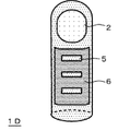
- FIG. 1 is a front view of the fingertip medical device 1A of the finger cot-shaped embodiment.
- FIG. 2A is an explanatory diagram of the position of the affected part in the body when the affected part is in the rectum.
- FIG. 2B is an explanatory diagram of a method of identifying the position of the affected portion in the rectum with the fingertip medical device 1A of the embodiment.
- FIG. 3 is a perspective view of the fingertip medical device 1B of the embodiment.
- FIG. 4 is a perspective view of the fingertip medical device 1C of the embodiment.
- FIG. 5 is a perspective view of the fingertip medical device 1D of the embodiment.
- FIG. 6 is a perspective view of the fingertip medical device 1E of the embodiment.
- FIG. 1 is a front view of the fingertip medical device 1A of the finger cot-shaped embodiment.
- FIG. 2A is an explanatory diagram of the position of the affected part in the body when the affected part is in the rectum.
- FIG. 2B
- FIG. 7 is a perspective view of the fingertip medical device 1F of the embodiment.
- FIG. 8 is a perspective view of the fingertip medical device 1G of the embodiment.
- FIG. 9A is a perspective view of the fingertip medical device 1H of the embodiment.
- FIG. 9B is a perspective view of the fingertip medical device 1H in the state of being attached to the glove.
- FIG. 10A is a perspective view of the fingertip medical device 1I of the embodiment.
- FIG. 10B is a perspective view of the fingertip medical device 1I in the state of being attached to the glove.
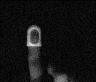
- FIG. 11A is an image of the fingertip medical device 1A taken by a digital color camera under white illumination.
- FIG. 11B is an image of the front surface of the silicone sheet when the fingertip medical device 1A of the embodiment is placed behind the silicone sheet and the front surface of the silicone sheet is photographed by a digital color camera under white illumination.
- FIG. 11C shows an image of the front surface of the silicone sheet when the fingertip medical device 1A of the embodiment is placed behind the silicone sheet, the front surface of the silicone sheet is irradiated with excitation light, and the front surface thereof is photographed by a near-infrared color system. is there.
- FIG. 1 is a front view of a finger cot-shaped medical device 1A for fingertips according to an embodiment of the present invention, and a broken line represents a hand having the finger cot-shaped medical device 1A for fingertips attached to a finger.
- the medical device for fingertips of the present invention has a resin layer that emits red fluorescence or near-infrared fluorescence adhered around the fingertips, particularly the pad of the finger or the pad of the finger.
- the fingertip medical device 1A has a length that covers the first joint of the finger from the fingertip when worn on the finger, and also has a fenestration portion that exposes at least the central portion of the finger pad. Has 2. The presence of the fenestration 2 allows the operator to easily perform palpation using the pad of the finger exposed from the fenestration 2.
- the size of the window opening portion 2 is preferably 5 to 15 mm in width w1 and 5 to 20 mm in length h1 from the viewpoint of enabling palpation.
- the resin layer of the fingertip medical device 1A fluoresces.
- the fenestration part 2 is dark and the circumference of the fenestration part 2 is observed brightly in a ring shape, and the position of the fenestration part, that is, the position of the affected part can be specified, but the affected part is more accurately observed.
- the width w1 of the window opening portion 2 is 10 to 15 mm and the length h1 is 10 to 20 mm from the viewpoint of making it possible to specify the position of.
- the size of the window opening portion 2 is too small, the light emitting portion observed from the serosa side does not form a ring shape, and the portion corresponding to the window opening portion 2 also appears to emit light. It becomes difficult to accurately identify the position, and conversely, if it is too large, it becomes difficult to identify where the affected area is in the darkly observed part.
- the fingertip medical device 1A is made of a resin that emits red fluorescence or near-infrared fluorescence.
- a resin that emits red fluorescence or near-infrared fluorescence for example, a flexible resin in which a fluorescent dye is kneaded can be used.
- the flexible resin a polyurethane, polypropylene, polyethylene, polyvinyl chloride, polyamide, polyamide elastomer or the like mixed with a curing agent, if necessary, can be used. It is preferable that the shore hardness after curing is 30A to 70A. Further, by using a resin having an elongation at the time of cutting of 300% or more, the fit feeling when the finger cot-shaped medical device for fingertips 1A is fitted to the fingertips is improved.
- the preferable thickness of the resin layer forming the finger cot shape is determined according to the emission intensity of the resin layer containing the fluorescent dye, and therefore varies depending on the type and concentration of the fluorescent dye, but usually the thickness is 0.1 to 2 mm. preferable.
- the fluorescent dye to be kneaded into the flexible resin is preferably one that fluoresces in the red to near infrared wavelength range of 600 to 1400 nm, preferably in the red light or near infrared light wavelength range of 700 to 1100 nm.
- Light in such a wavelength range is highly permeable to human tissues such as skin, fat, and muscle, and can reach the serosal surface from the mucous membrane of tubular human tissues such as the rectum.
- Examples of the fluorescent dye that emits fluorescence in the above-mentioned wavelength range include riboflavin, thiamine, NADH (nicotinamide adenine dinucleotide), indocyanine green (ICG), and the azo-boron complex compound described in JP-A-2011-162445, WO 2016/132596. Examples thereof include dyes having a fused ring structure described in Japanese Patent Publication No.
- the preferable concentration of the fluorescent dye in the resin that emits near-infrared fluorescence is determined according to the type of the fluorescent dye and the resin used as the binder, and is usually preferably 0.001 to 1% by mass.
- the fluorescent dye is kneaded into the resin using a biaxial kneader. After that, it may be formed into a finger cot shape by extrusion molding or injection molding.
- a contrast agent such as barium sulfate may be added to the fluorescent resin, if necessary.
- the medical device 1A for fingertips As a method of using the medical device 1A for fingertips, for example, when the position X of the rectal cancer shown in FIG. 2A can be identified from the serosa side, first, the operator's hand, preferably the operator wearing surgical gloves. As shown in FIG. 1, a finger cot-shaped medical device for fingertips 1A is fitted to the fingers of the hand. In this case, the opening portion 2 is positioned on the pad of the finger.
- a finger fitted with a finger cot-shaped medical device for fingertips 1A is inserted into the rectum from the anus, the rectum is palpated to locate the cancer, and the finger is exposed from the fenestration 2. Hold down the cancer with the pad of your finger. Then, the serosa side of the rectum is irradiated with excitation light for emitting red fluorescence or near-infrared fluorescence to the resin forming the fingertip medical device 1A, and the fluorescence emitted by the fingertip medical device 1A is emitted from the serosa side. Observe.
- the serosa of the rectum may be exposed by laparotomy and the excitation light may be irradiated there.
- a surgical endoscope is inserted through a hole made in the abdominal wall and irradiated from the serosa side. You may.
- the wavelength of the excitation light is shorter than the wavelength of fluorescence, but the wavelength range of the excitation light that emits red fluorescence or near-infrared fluorescence is also highly transparent to human tissue, and the excitation light irradiated to the serous membrane side is the tissue of the rectum or It is absorbed by the fingertip medical device 1A on the mucosal side with almost no inhibition of absorption by blood, and the resin layer of the fingertip medical device 1A emits red fluorescence or near-infrared fluorescence.
- the fluorescence when the fluorescence is red, it is observed with the naked eye, when the fluorescence is near infrared, it is observed through a known infrared visual conversion glass, or the rectum is photographed from the serosa side, and the near infrared is imaged.
- the ring-shaped light emission by the fingertip medical device 1A can be easily observed from the serosa side, and further, the dark part due to the fenestration 2 inside the ring-shaped light emitting part is the development of cancer. It can be specified as a position. If the position of the cancer can be identified from the serosal side in this way, a mark can be made with an electric knife, and the mark can be used as a guide when excising the affected area.
- the application scene of the medical device for fingertips 1A of the present invention is not limited to specifying the position of the affected part within the range where the finger is inserted from the outside of the human body as in the rectum described above.
- a finger equipped with a fingertip medical device 1A is inserted into a hole made in the abdominal wall for insertion of a laparoscope or a surgical instrument, and further inserted into the gastric cavity through a hole made in the stomach wall to insert the affected part in the gastric mucosa. It can also be used to specify the position of the gastric serosa.
- the position of the affected area can also be specified by the light emission of the fluorescent dye-containing resin attached to the clip by sandwiching the mucous membrane of the affected area with a metal clip described in Japanese Patent No. 1661096 and observing from the serosa side.
- a metal clip described in Japanese Patent No. 1661096 and observing from the serosa side.
- the metal clip will hit the scalpel during excision of the affected area and the scalpel will be damaged.
- the medical device for fingertips of the present invention even if the medical device for fingertips comes off from the operator's finger in the living body and the scalpel hits the medical device for fingertips when excising the affected part, the scalpel is damaged. There is no fear.
- the medical device for fingertips of the present invention can take various aspects.
- the fingertip medical device 1B shown in FIG. 3 has a take-out thread 3 attached to the end of the fingertip medical device 1A shown in FIG. 1 by adhesion or welding. Since the extraction thread 3 is attached to the fingertip medical device 1B, even if the fingertip medical device 1B comes off from the fingertip in the body, the fingertip medical device 1B can be easily inserted into the body by picking and pulling the extraction thread 3. Can be taken out from.
- the fingertip medical device 1C shown in FIG. 4 has a length of the fingertip medical device 1A shown in FIG. 1 so as to cover the second joint from the fingertip, and is below the fenestration portion 2 (that is, that is).
- Scales 4 are provided at predetermined intervals with an infrared or near-infrared light opaque resin on the finger insertion opening side).
- the scale was punched out in a scale shape instead of being formed of an infrared or near infrared light opaque resin.
- Infrared or near-infrared light impervious by attaching an infrared or near-infrared light opaque resin film 6 having holes 5 to a medical device main body 1, printing an infrared or near-infrared light opaque resin layer, or the like. It is provided with a permeable resin layer.
- the fingertip medical device 1D Since a resin that emits infrared or near-infrared fluorescence is exposed from this hole 5, when the fingertip medical device 1D is observed from the serous membrane side by irradiating with excitation light, the fingertip medical device fitted to the finger is used.
- the window opening portion 2 On the fingertip side of the tool 1D, the window opening portion 2 can be observed as a dark portion in the finger cot type light emitting region, and a scale that emits light in the dark portion region can be observed below the window opening portion.
- the fingertip medical device 1E shown in FIG. 6 has a finger cot shape having a window opening 2 similar to the fingertip medical device 1C shown in FIG. 4, and covers from the fingertip to the second joint. It has a length to be used.
- the finger cot shape itself is made of a resin 15 that does not contain a fluorescent dye that emits red light fluorescence or near infrared fluorescence.
- a ring-shaped resin layer 8 is formed around the window opening portion 2 by applying a paint containing a fluorescent dye that emits red fluorescence or near-infrared fluorescence.
- a scale 4 is formed on the lower side of the window opening portion 2 by a paint containing a fluorescent dye that emits red fluorescence or near-infrared fluorescence.
- the fingertip medical device 1E can be used in the same manner as the fingertip medical device 1C shown in FIG.
- the medical device for fingertips of the present invention is a finger cot type having a window opening portion
- the medical device for fingertips is formed of a resin that emits red fluorescence or near-infrared fluorescence.
- the circumference of the window opening may be formed of a resin that emits red fluorescence or near-infrared fluorescence. Therefore, the entire finger cot shape may be formed of this resin as in the fingertip medical device 1A shown in FIG. 1, and the window opening portion 2 may be formed as in the fingertip medical device 1E shown in FIG.
- a resin layer 8 that emits red fluorescence or near-infrared fluorescence may be formed around the coating layer.
- the fingertip medical device 1F shown in FIG. 7 has a glove shape, and has a ring-shaped printing layer 8 formed of a resin that emits red or near-infrared fluorescence on the pad of the index finger of the glove 7. ing.
- the ring-shaped printing layer 8 is formed so as to surround the central portion of the pad of the finger.
- the position of the affected area is specified by palpation with the fingertip having the ring-shaped printing layer 8 of the hand on which the fingertip medical device 1F is fitted. Then, excitation light is irradiated from the serosa side to cause the ring-shaped printing layer 8 to emit red or near-infrared fluorescence, and the fluorescence is observed from the serosa side in the same manner as in the fingertip medical device 1A shown in FIG.
- the affected area can be accurately identified as a dark area inside the ring-shaped light emitting area formed by the printing layer 8.
- the fingertip medical device 1G shown in FIG. 8 replaces the ring-shaped printing layer 8 formed of a resin that emits red fluorescence or near-infrared fluorescence in the glove-shaped fingertip medical device 1F shown in FIG. A circular printing layer 9 made of the same resin is provided.
- the affected part can be accurately identified as a circular light emitting part by observing the fluorescent light emitting part from the serosa side as in the fingertip medical device 1A shown in FIG. ..
- the fingertip medical device 1H shown in FIG. 9A is formed on one side of a ring-shaped resin layer 10 formed of a resin that emits red fluorescence or near-infrared fluorescence, similar to the ring-shaped printing layer 8 shown in FIG.
- This is a seal-shaped medical device for fingertips provided with an adhesive layer and the adhesive layer attached on the release film 11.
- the resin layer 10 of the seal-shaped medical device for fingertips 1H preferably has a size that can be attached to the inside of the finger pad. Therefore, the fingertip medical device 1H is peeled off from the release film 11, and as shown in FIG. 9B, the ring-shaped resin layer 10 is attached to the surgical glove 12, so that the glove-shaped fingertip medical treatment shown in FIG. 7 is attached. A configuration substantially similar to that of the tool 1F can be obtained. According to the fingertip medical device 1H, the fingertip medical device of the present invention can be constructed at a lower cost by using the surgical gloves 12 that are used on a daily basis.
- the ring-shaped resin layer 10 may be directly attached to the pad of the finger, and the surgical gloves 12 may be worn on the ring-shaped resin layer 10. This makes it possible to eliminate the possibility that the ring-shaped resin layer 10 will come off into the body during palpation.
- the fingertip medical device 1I shown in FIG. 10A is a seal-shaped fingertip medical device in which the ring-shaped resin layer 10 is formed on the circular resin layer 13 in the fingertip medical device 1H shown in FIG. 9A.
- the fingertip medical device 1I is also peeled off from the release film 11, and a circular resin layer 13 is attached to the surgical glove 12 as shown in FIG. 10B to obtain the glove-shaped fingertip medical device 1G shown in FIG.
- a substantially similar configuration can be obtained.
- a circular resin layer 13 is directly attached to the pad of the finger, a surgical glove 12 is worn over the circular resin layer 13, and the circular resin layer 13 is peeled off into the body. The fear may be eliminated.
- the fingertip medical device of the present invention has a sticker shape like the above-mentioned fingertip medical device 1H and 1I, in order to prevent palpation with the fingertip to which the sticker-shaped fingertip medical device is attached, the palpation is not hindered.
- the resin layers 10 and 13 to be attached to the finger have the same thinness and flexibility as surgical gloves. Therefore, the thickness of the resin layer to be attached to the finger is 0.1 to 0.3 mm, and the tensile force at the time of cutting is 9.0 N or more, similar to the physical characteristics of surgical gloves specified in JIS T9107. It is preferable that the elongation at cutting is 600% or more and the tensile force at 300% elongation is 3.0 N or less.
- the take-out thread 3 may be provided on the finger cot-shaped medical devices 1C and 1D shown in FIGS. 4 and 5.
- a dye having a condensed ring structure described in WO2016 / 132596 is kneaded with ABS resin to produce a finger cot type medical device 1A for fingertips having a thickness of 2 mm and shown in FIG. 1, and the medical device 1A for fingertips is manufactured. I put it on my finger. An image of a fingertip medical device 1A fitted on a finger taken with white illumination is shown in FIG. 11A.
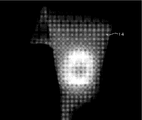
- the fingertip medical device fitted to the finger was placed behind the silicone sheet (thickness 3 mm) 14 that imitated human tissue, and was photographed with a digital color camera from the front of the silicone sheet 14 under white lighting. This image is shown in FIG. 11B.
- excitation light (wavelength 740 to 760 nm) was irradiated from the front surface of the silicone sheet 14, and the front surface was photographed with a near infrared color camera system (Mizuho Co., Ltd.).
- This image is shown in FIG. 11C.
- a dark portion corresponding to the window opening portion 2 could be observed inside the finger cot type light emitting portion. Therefore, it can be seen that the position of the affected part can be specified from the serosa side by pressing the affected part on the mucosal side of the body cavity with the pad of the finger exposed from the window opening portion 2 of the fingertip medical device 1A and irradiating with excitation light.
Abstract
This medical tool for a fingertip comprises a resin layer that emits red fluorescence or near infrared fluorescence, and is to be worn on a fingertip. More specifically, the medical tool for a fingertip 1A to 1E has a finger cot shape, has an open window portion 2 from which the finger pad is exposed when worn on a finger, and is formed of a resin that emits red fluorescence or near infrared fluorescence. Alternatively, the medical tool for a fingertip 1F, 1G has a glove shape and has a print layer 8, 9 on the finger pad thereof or around the finger pad thereof, the print layer being formed of a resin that emits red fluorescence or near infrared fluorescence. Alternatively, the medical tool for a fingertip 1H, 1I is like a sticker that has an adhesive layer on one surface of a resin layer that emits red fluorescence or near infrared fluorescence, and is sized so as to be affixed within the finger pad. When an operator who performs palpation in a living body wears this medical tool for a fingertip on a fingertip, the location of a lesion identified from a mucosal side by palpation can be accurately identified from a serosal side.
Description
本発明は、赤色又は近赤外蛍光を発光する樹脂層を有し、該樹脂層を指先に被着させる指先用医療用具に関する。
The present invention relates to a medical device for fingertips that has a resin layer that emits red or near-infrared fluorescence, and the resin layer is adhered to a fingertip.
直腸等の管状の人体組織の粘膜に発生した癌等の診断に、内視鏡が使用されている。診断には術者の指を体内に挿入する触診も併用される。そこで、指サックの先端部に撮像装置を取り付けると共に、指サックに触診用の開窓部を設けることが提案されている(特許文献1)。
An endoscope is used to diagnose cancers that have developed in the mucous membranes of tubular human tissues such as the rectum. Palpation, in which the operator's finger is inserted into the body, is also used for diagnosis. Therefore, it has been proposed to attach an imaging device to the tip of the finger cot and to provide the finger cot with a window opening for palpation (Patent Document 1).
特許文献1に記載の指サックを指に装着し、その指を直腸等の管状の人体組織に挿入することにより、管状の人体組織の粘膜側の表面状態を観察できると共に、粘膜側組織の触診を行うことが可能となり、さらに、癌の除去の処置が必要になった場合には、患部を観察しつつ穿刺処置を行うことが可能となる。
By attaching the finger cot described in Patent Document 1 to a finger and inserting the finger into a tubular human tissue such as the rectum, the surface condition of the tubular human tissue on the mucosal side can be observed and the mucosal tissue can be palpated. Furthermore, when it becomes necessary to remove the cancer, it is possible to perform the puncture treatment while observing the affected area.
一方、管状の人体組織の粘膜に発生した癌を外科的に切除する場合には、癌の位置を管状の人体組織の漿膜側から特定することが必要となる。しかしながら、特許文献1に記載の指サックを用いても癌の位置を漿膜側から特定することはできない。そのため、例えば、内視鏡や触診で直腸癌があると診断された場合、標準的には、診断された癌の位置に前後2cm程度のマージンをもたせた範囲を切除することが行われており、これにより癌の存在が確認されていない肛門が切除され、人工肛門が必要になる場合もある。
On the other hand, when surgically removing the cancer that has developed on the mucous membrane of the tubular human tissue, it is necessary to identify the position of the cancer from the serosal side of the tubular human tissue. However, even if the finger cot described in Patent Document 1 is used, the position of the cancer cannot be specified from the serosal side. Therefore, for example, when rectal cancer is diagnosed by endoscopy or palpation, it is standard to excise the area where the diagnosed cancer has a margin of about 2 cm in the anterior-posterior direction. This may remove the anus for which the presence of cancer has not been confirmed, and may require an artificial anus.
これに対し、本発明は、直腸等の管状の人体組織の粘膜を触診することにより医師が患部の位置を特定した場合に、その位置を管状の人体組織の漿膜側から特定できるようにすることを課題とする。
On the other hand, the present invention makes it possible to identify the position of the affected area from the serosa side of the tubular human tissue when the doctor identifies the position of the affected area by palpating the mucous membrane of the tubular human tissue such as the rectum. Is the subject.
本発明者は、触診を行う指の先端部に赤色蛍光又は近赤外蛍光を発する樹脂層を被着させると、該樹脂層が発光する蛍光を漿膜側から観察することで、触診により粘膜側で特定した患部の位置を漿膜側から特定できることを想到し、本発明を完成させた。
The present inventor adheres a resin layer that emits red fluorescence or near-infrared fluorescence to the tip of a finger to be palpated, and observes the fluorescence emitted by the resin layer from the serosa side to the mucosal side by palpation. The present invention was completed with the idea that the position of the affected area identified in 1 can be specified from the serosa side.
即ち、本発明は、赤色蛍光又は近赤外蛍光を発する樹脂層を有する、指先に被着される指先用医療用具を提供する。
That is, the present invention provides a medical device for fingertips that has a resin layer that emits red fluorescence or near-infrared fluorescence and is adhered to the fingertips.
本発明によれば、指先に赤色蛍光又は近赤外蛍光を発する樹脂層を被着させることができるので、該樹脂層が発光する蛍光を観察することで、粘膜側の触診で特定された患部の位置を漿膜側から特定することが可能となる。したがって、粘膜側の触診で特定された患部を外科的に切除する場合に、患部の位置を精確に特定できないために必要とされていた切除範囲のマージンを顕著に低減させるか、不用とすることができ、切除範囲を必要最小限にすることができる。よって、例えば、従前では不用に切除されていた肛門を温存することが可能となり、患者の負担が軽減する。
According to the present invention, a resin layer that emits red fluorescence or near-infrared fluorescence can be adhered to the fingertips. Therefore, by observing the fluorescence emitted by the resin layer, the affected area identified by palpation on the mucosal side It is possible to specify the position of the resin from the serosal side. Therefore, when surgically excising the affected area identified by palpation on the mucosal side, the margin of the excision range required because the location of the affected area cannot be accurately determined should be significantly reduced or eliminated. And the excision range can be minimized. Therefore, for example, it becomes possible to preserve the anus that was previously unnecessarily excised, and the burden on the patient is reduced.
また、本発明によれば触診が可能であるため、粘膜の硬さから癌の大きさなどについて正確に診断することが可能となる。
Further, according to the present invention, since palpation is possible, it is possible to accurately diagnose the size of cancer from the hardness of the mucous membrane.
以下、図面を参照しつつ本発明を詳細に説明する。なお、各図中、同一符号は同一又は同等の構成要素を表している。
Hereinafter, the present invention will be described in detail with reference to the drawings. In each figure, the same reference numerals represent the same or equivalent components.
(指サック形状の指先用医療用具)
図1は、指サック形状を有する、本発明の一実施例の指先用医療用具1Aの正面図であって、破線はこの指サック形状の指先用医療用具1Aを指に装着した手を表している。このように、本発明の指先用医療用具は、指先、特に指の腹又は指の腹の周りに、赤色蛍光又は近赤外蛍光を発する樹脂層を被着させる。より具体的には、この指先用医療用具1Aは、指に装着したときに指先から指の第1関節を覆う長さを有し、また、指の腹の少なくとも中央部を露出させる開窓部2を有する。開窓部2があることにより術者は、開窓部2から露出した指の腹を用いて容易に触診を行うことができる。 (Finger cot-shaped medical device for fingertips)
FIG. 1 is a front view of a finger cot-shapedmedical device 1A for fingertips according to an embodiment of the present invention, and a broken line represents a hand having the finger cot-shaped medical device 1A for fingertips attached to a finger. There is. As described above, the medical device for fingertips of the present invention has a resin layer that emits red fluorescence or near-infrared fluorescence adhered around the fingertips, particularly the pad of the finger or the pad of the finger. More specifically, the fingertip medical device 1A has a length that covers the first joint of the finger from the fingertip when worn on the finger, and also has a fenestration portion that exposes at least the central portion of the finger pad. Has 2. The presence of the fenestration 2 allows the operator to easily perform palpation using the pad of the finger exposed from the fenestration 2.
図1は、指サック形状を有する、本発明の一実施例の指先用医療用具1Aの正面図であって、破線はこの指サック形状の指先用医療用具1Aを指に装着した手を表している。このように、本発明の指先用医療用具は、指先、特に指の腹又は指の腹の周りに、赤色蛍光又は近赤外蛍光を発する樹脂層を被着させる。より具体的には、この指先用医療用具1Aは、指に装着したときに指先から指の第1関節を覆う長さを有し、また、指の腹の少なくとも中央部を露出させる開窓部2を有する。開窓部2があることにより術者は、開窓部2から露出した指の腹を用いて容易に触診を行うことができる。 (Finger cot-shaped medical device for fingertips)
FIG. 1 is a front view of a finger cot-shaped
開窓部2の大きさは、触診を可能とする点からは幅w1を5~15mm、長さh1を5~20mmとすることが好ましい。一方、後述するように、人体組織の粘膜側の患部に指先用医療用具1Aの開窓部を当てて励起光を照射すると、指先用医療用具1Aの樹脂層が蛍光を発するので、その蛍光像を漿膜側から観察すると、開窓部2は暗く、開窓部2の周りがリング状に明るく観察され、開窓部の位置、即ち患部の位置を特定することができるが、より精確に患部の位置を特定できるようにする点からは開窓部2の幅w1を10~15mm、長さh1を10~20mmとすることが好ましい。これに対し、開窓部2の大きさが小さすぎると、漿膜側から観察される発光部分がリング状にならず、開窓部2に対応する部分も発光しているように見えるので患部の位置を精確に特定することが難しくなり、反対に大きすぎても暗く観察される部分のどこに患部があるのかを特定することが難しくなる。
The size of the window opening portion 2 is preferably 5 to 15 mm in width w1 and 5 to 20 mm in length h1 from the viewpoint of enabling palpation. On the other hand, as will be described later, when the window portion of the fingertip medical device 1A is applied to the affected part on the mucous membrane side of the human body tissue and irradiated with excitation light, the resin layer of the fingertip medical device 1A fluoresces. When observing from the serosa side, the fenestration part 2 is dark and the circumference of the fenestration part 2 is observed brightly in a ring shape, and the position of the fenestration part, that is, the position of the affected part can be specified, but the affected part is more accurately observed. It is preferable that the width w1 of the window opening portion 2 is 10 to 15 mm and the length h1 is 10 to 20 mm from the viewpoint of making it possible to specify the position of. On the other hand, if the size of the window opening portion 2 is too small, the light emitting portion observed from the serosa side does not form a ring shape, and the portion corresponding to the window opening portion 2 also appears to emit light. It becomes difficult to accurately identify the position, and conversely, if it is too large, it becomes difficult to identify where the affected area is in the darkly observed part.
(指先用医療用具を形成する樹脂)
指先用医療用具1Aは、赤色蛍光又は近赤外蛍光を発する樹脂で形成されている。赤色蛍光又は近赤外蛍光を発する樹脂としては、例えば、蛍光色素を混練りした可撓性樹脂を使用することができる。ここで可撓性樹脂としては、ポリウレタン、ポリプロピレン、ポリエチレン、ポリ塩化ビニル、ポリアミド、ポリアミドエラストマー等に、必要に応じて硬化剤を配合したものを使用することができる。硬化後のショア硬度が30A~70Aとなるものが好ましい。また、切断時伸びが300%以上の樹脂を使用することにより、指サック形状の指先用医療用具1Aを指先に嵌めたときのフィット感が良好となる。 (Resin that forms medical devices for fingertips)
The fingertipmedical device 1A is made of a resin that emits red fluorescence or near-infrared fluorescence. As the resin that emits red fluorescence or near-infrared fluorescence, for example, a flexible resin in which a fluorescent dye is kneaded can be used. Here, as the flexible resin, a polyurethane, polypropylene, polyethylene, polyvinyl chloride, polyamide, polyamide elastomer or the like mixed with a curing agent, if necessary, can be used. It is preferable that the shore hardness after curing is 30A to 70A. Further, by using a resin having an elongation at the time of cutting of 300% or more, the fit feeling when the finger cot-shaped medical device for fingertips 1A is fitted to the fingertips is improved.
指先用医療用具1Aは、赤色蛍光又は近赤外蛍光を発する樹脂で形成されている。赤色蛍光又は近赤外蛍光を発する樹脂としては、例えば、蛍光色素を混練りした可撓性樹脂を使用することができる。ここで可撓性樹脂としては、ポリウレタン、ポリプロピレン、ポリエチレン、ポリ塩化ビニル、ポリアミド、ポリアミドエラストマー等に、必要に応じて硬化剤を配合したものを使用することができる。硬化後のショア硬度が30A~70Aとなるものが好ましい。また、切断時伸びが300%以上の樹脂を使用することにより、指サック形状の指先用医療用具1Aを指先に嵌めたときのフィット感が良好となる。 (Resin that forms medical devices for fingertips)
The fingertip
指サック形状を形成する樹脂層の好ましい厚さは、蛍光色素を含有した樹脂層の発光強度に応じて定まり、したがって、蛍光色素の種類や濃度によって異なるが、通常厚さ0.1~2mmが好ましい。
The preferable thickness of the resin layer forming the finger cot shape is determined according to the emission intensity of the resin layer containing the fluorescent dye, and therefore varies depending on the type and concentration of the fluorescent dye, but usually the thickness is 0.1 to 2 mm. preferable.
(蛍光色素)
可撓性樹脂に混練りする蛍光色素としては、600~1400nmの赤色乃至近赤外の波長域、好ましくは700~1100nmの赤色光又は近赤外光の波長域で蛍光を発するものが好ましい。このような波長域の光は、皮膚、脂肪、筋肉等の人体組織に対して透過性が高く、例えば、直腸等の管状の人体組織の粘膜から漿膜面まで良好に到達することができる。 (Fluorescent dye)
The fluorescent dye to be kneaded into the flexible resin is preferably one that fluoresces in the red to near infrared wavelength range of 600 to 1400 nm, preferably in the red light or near infrared light wavelength range of 700 to 1100 nm. Light in such a wavelength range is highly permeable to human tissues such as skin, fat, and muscle, and can reach the serosal surface from the mucous membrane of tubular human tissues such as the rectum.
上述の波長域の蛍光を発する蛍光色素としては、リボフラビン、チアミン、NADH(nicotinamide adenine dinucleotide)、インドシアニングリーン(ICG)、特開2011-162445号公報に記載のアゾ-ホウ素錯体化合物、WO2016/132596号公報に記載の縮合環構造を有する色素等をあげることができる。
Examples of the fluorescent dye that emits fluorescence in the above-mentioned wavelength range include riboflavin, thiamine, NADH (nicotinamide adenine dinucleotide), indocyanine green (ICG), and the azo-boron complex compound described in JP-A-2011-162445, WO 2016/132596. Examples thereof include dyes having a fused ring structure described in Japanese Patent Publication No.
近赤外蛍光を発する樹脂における蛍光色素の好ましい濃度は当該蛍光色素やバインダーとする樹脂の種類等に応じて定まり、通常、0.001~1質量%とすることが好ましい。
The preferable concentration of the fluorescent dye in the resin that emits near-infrared fluorescence is determined according to the type of the fluorescent dye and the resin used as the binder, and is usually preferably 0.001 to 1% by mass.
可撓性樹脂に蛍光色素を含有させる方法としては、例えば、二軸混練機を使用して樹脂に蛍光色素を混練する。その後、押出成形または射出成形にて指サック形状に成形すればよい。
As a method of incorporating the fluorescent dye into the flexible resin, for example, the fluorescent dye is kneaded into the resin using a biaxial kneader. After that, it may be formed into a finger cot shape by extrusion molding or injection molding.
(添加剤)
蛍光樹脂には、必要に応じて硫酸バリウム等の造影剤を添加してもよい。これにより、生体内で指先用医療用具1Aが指から外れても、生体内の指先用医療用具1Aを、X線を用いて撮影することにより追跡することが可能となる。 (Additive)
A contrast agent such as barium sulfate may be added to the fluorescent resin, if necessary. As a result, even if the fingertipmedical device 1A is removed from the finger in the living body, the fingertip medical device 1A in the living body can be tracked by photographing with X-rays.
蛍光樹脂には、必要に応じて硫酸バリウム等の造影剤を添加してもよい。これにより、生体内で指先用医療用具1Aが指から外れても、生体内の指先用医療用具1Aを、X線を用いて撮影することにより追跡することが可能となる。 (Additive)
A contrast agent such as barium sulfate may be added to the fluorescent resin, if necessary. As a result, even if the fingertip
(指先用医療用具の使用方法)
指先用医療用具1Aの使用方法としては、例えば、図2Aに示す直腸癌の位置Xを漿膜側から特定できるようにする場合、まず、術者の手、好ましくは手術用手袋を嵌めた術者の手の指に図1に示すように指サック形状の指先用医療用具1Aを嵌める。この場合、指の腹上に開窓部2を位置させる。 (How to use medical equipment for fingertips)
As a method of using themedical device 1A for fingertips, for example, when the position X of the rectal cancer shown in FIG. 2A can be identified from the serosa side, first, the operator's hand, preferably the operator wearing surgical gloves. As shown in FIG. 1, a finger cot-shaped medical device for fingertips 1A is fitted to the fingers of the hand. In this case, the opening portion 2 is positioned on the pad of the finger.
指先用医療用具1Aの使用方法としては、例えば、図2Aに示す直腸癌の位置Xを漿膜側から特定できるようにする場合、まず、術者の手、好ましくは手術用手袋を嵌めた術者の手の指に図1に示すように指サック形状の指先用医療用具1Aを嵌める。この場合、指の腹上に開窓部2を位置させる。 (How to use medical equipment for fingertips)
As a method of using the
次に、図2Bに示すように、指サック形状の指先用医療用具1Aを嵌めた指を肛門から直腸に挿入し、直腸を触診して癌の位置を特定し、開窓部2から露出している指の腹で癌を押さえる。そして、直腸の漿膜側に、指先用医療用具1Aを形成している樹脂に赤色蛍光又は近赤外蛍光を発光させるための励起光を照射し、指先用医療用具1Aが発する蛍光を漿膜側から観察する。
Next, as shown in FIG. 2B, a finger fitted with a finger cot-shaped medical device for fingertips 1A is inserted into the rectum from the anus, the rectum is palpated to locate the cancer, and the finger is exposed from the fenestration 2. Hold down the cancer with the pad of your finger. Then, the serosa side of the rectum is irradiated with excitation light for emitting red fluorescence or near-infrared fluorescence to the resin forming the fingertip medical device 1A, and the fluorescence emitted by the fingertip medical device 1A is emitted from the serosa side. Observe.
ここで、励起光の照明方法としては、開腹により直腸の漿膜を露出させ、そこに励起光を照射してもよく、手術用内視鏡を腹壁に開けた孔から挿入し、漿膜側から照射しても良い。励起光の波長は蛍光の波長よりも短いが、赤色蛍光又は近赤外蛍光を発光させる励起光の波長域も人体組織に対する透過性が高く、漿膜側に照射された励起光は直腸の組織や血液で殆ど吸収阻害されることなく、粘膜側にある指先用医療用具1Aで吸収され、指先用医療用具1Aの樹脂層が赤色蛍光又は近赤外蛍光を発する。したがって、蛍光が赤色の場合には肉眼観察により、蛍光が近赤外の場合には公知の赤外可視変換ガラスを通して観察することにより、あるいは直腸を漿膜側から撮影し、画像処理で近赤外蛍光を可視化することにより、容易に指先用医療用具1Aによるリング状の発光を漿膜側から観察することができ、さらに、リング状の発光部の内側の、開窓部2による暗部を癌の発生位置として特定できる。こうして漿膜側から癌の位置を特定できると、電気メスで印をつけ、患部の切除時にはその印を目安にすることができる。
Here, as a method of illuminating the excitation light, the serosa of the rectum may be exposed by laparotomy and the excitation light may be irradiated there. A surgical endoscope is inserted through a hole made in the abdominal wall and irradiated from the serosa side. You may. The wavelength of the excitation light is shorter than the wavelength of fluorescence, but the wavelength range of the excitation light that emits red fluorescence or near-infrared fluorescence is also highly transparent to human tissue, and the excitation light irradiated to the serous membrane side is the tissue of the rectum or It is absorbed by the fingertip medical device 1A on the mucosal side with almost no inhibition of absorption by blood, and the resin layer of the fingertip medical device 1A emits red fluorescence or near-infrared fluorescence. Therefore, when the fluorescence is red, it is observed with the naked eye, when the fluorescence is near infrared, it is observed through a known infrared visual conversion glass, or the rectum is photographed from the serosa side, and the near infrared is imaged. By visualizing the fluorescence, the ring-shaped light emission by the fingertip medical device 1A can be easily observed from the serosa side, and further, the dark part due to the fenestration 2 inside the ring-shaped light emitting part is the development of cancer. It can be specified as a position. If the position of the cancer can be identified from the serosal side in this way, a mark can be made with an electric knife, and the mark can be used as a guide when excising the affected area.
本発明の指先用医療用具1Aの適用場面は、上述の直腸のように人体の外部から指を挿入して届く範囲の患部の位置の特定に限らない。例えば、指先用医療用具1Aを装着した指を、腹腔鏡や手術器具の挿入のために腹壁に開けた孔に挿入し、さらに胃壁に開けた孔から胃腔内に挿入し、胃粘膜における患部の位置を胃漿膜側から特定する場合にも使用することができる。
The application scene of the medical device for fingertips 1A of the present invention is not limited to specifying the position of the affected part within the range where the finger is inserted from the outside of the human body as in the rectum described above. For example, a finger equipped with a fingertip medical device 1A is inserted into a hole made in the abdominal wall for insertion of a laparoscope or a surgical instrument, and further inserted into the gastric cavity through a hole made in the stomach wall to insert the affected part in the gastric mucosa. It can also be used to specify the position of the gastric serosa.
なお、例えば特許6161096号公報に記載の金属製のクリップで患部の粘膜を挟持し、漿膜側から観察することによっても、該クリップに取り付けられている蛍光色素含有樹脂の発光により患部の位置を特定することができるが、患部の切除時に金属製のクリップがメスに当たり、メスが破損する虞がある。これに対し、本発明の指先用医療用具によれば、仮に生体内で指先用医療用具が術者の指から外れ、患部の切除時にその指先用医療用具にメスが当たってもメスが破損する虞は無い。
The position of the affected area can also be specified by the light emission of the fluorescent dye-containing resin attached to the clip by sandwiching the mucous membrane of the affected area with a metal clip described in Japanese Patent No. 1661096 and observing from the serosa side. However, there is a risk that the metal clip will hit the scalpel during excision of the affected area and the scalpel will be damaged. On the other hand, according to the medical device for fingertips of the present invention, even if the medical device for fingertips comes off from the operator's finger in the living body and the scalpel hits the medical device for fingertips when excising the affected part, the scalpel is damaged. There is no fear.
(指先用医療用具の変形態様)
本発明の指先用医療用具は種々の態様をとることができる。例えば、図3に示した指先用医療用具1Bは、図1に示した指先用医療用具1Aの端部に取出糸3を接着又は溶着により取り付けたものである。指先用医療用具1Bに取出糸3が取り付けられていることにより、体内で指先用医療用具1Bが指先から外れても、取出糸3を摘まんで引っ張ることにより、容易に指先用医療用具1Bを体内から取り出すことができる。 (Modification of medical device for fingertips)
The medical device for fingertips of the present invention can take various aspects. For example, the fingertip medical device 1B shown in FIG. 3 has a take-out thread 3 attached to the end of the fingertipmedical device 1A shown in FIG. 1 by adhesion or welding. Since the extraction thread 3 is attached to the fingertip medical device 1B, even if the fingertip medical device 1B comes off from the fingertip in the body, the fingertip medical device 1B can be easily inserted into the body by picking and pulling the extraction thread 3. Can be taken out from.
本発明の指先用医療用具は種々の態様をとることができる。例えば、図3に示した指先用医療用具1Bは、図1に示した指先用医療用具1Aの端部に取出糸3を接着又は溶着により取り付けたものである。指先用医療用具1Bに取出糸3が取り付けられていることにより、体内で指先用医療用具1Bが指先から外れても、取出糸3を摘まんで引っ張ることにより、容易に指先用医療用具1Bを体内から取り出すことができる。 (Modification of medical device for fingertips)
The medical device for fingertips of the present invention can take various aspects. For example, the fingertip medical device 1B shown in FIG. 3 has a take-out thread 3 attached to the end of the fingertip
なお、取出糸3を指先用医療用具本体1に強固に取り付けるため、取出糸3の接着領域3aの長さを十分に確保することが好ましい。
It is preferable to secure a sufficient length of the adhesive region 3a of the take-out thread 3 in order to firmly attach the take-out thread 3 to the main body 1 of the medical device for fingertips.
図4に示した指先用医療用具1Cは、図1に示した指先用医療用具1Aにおいて長さを指先から第2関節が覆われるように長くし、開窓部2よりも下側(即ち、指挿入口側)に赤外又は近赤外光不透過性樹脂で目盛り4を所定間隔に付したものである。これにより、漿膜側から粘膜側にある指先用医療用具1Cを観察した場合に、指サック型の発光領域内に開窓部2と目盛り4が暗部として観察され、この目盛りを患部の切除マージンの目安に使用することができる。
The fingertip medical device 1C shown in FIG. 4 has a length of the fingertip medical device 1A shown in FIG. 1 so as to cover the second joint from the fingertip, and is below the fenestration portion 2 (that is, that is). Scales 4 are provided at predetermined intervals with an infrared or near-infrared light opaque resin on the finger insertion opening side). As a result, when observing the fingertip medical device 1C from the serosa side to the mucosal side, the fenestration portion 2 and the scale 4 are observed as dark areas in the finger cot type light emitting region, and these scales are used as the excision margin of the affected area. It can be used as a guide.
図5に示した指先用医療用具1Dは、図4に示した指先用医療用具1Cにおいて、目盛りを赤外又は近赤外光不透過性樹脂で形成したのに代えて、目盛り状に打ち抜いた孔5を有する赤外又は近赤外光不透過性樹脂フィルム6の医療用具本体1への貼付、赤外又は近赤外光不透過性樹脂層の印刷等により赤外又は近赤外光不透過性樹脂層を設けたものである。この孔5からは赤外又は近赤外蛍光を発光する樹脂が露出しているので、励起光を照射し、漿膜側から指先用医療用具1Dを観察した場合に、指に嵌めた指先用医療用具1Dの指先側では指サック型の発光領域内に開窓部2が暗部として観察され、開窓部の下側には暗部領域に発光する目盛りを観察することができる。
In the fingertip medical device 1D shown in FIG. 5, in the fingertip medical device 1C shown in FIG. 4, the scale was punched out in a scale shape instead of being formed of an infrared or near infrared light opaque resin. Infrared or near-infrared light impervious by attaching an infrared or near-infrared light opaque resin film 6 having holes 5 to a medical device main body 1, printing an infrared or near-infrared light opaque resin layer, or the like. It is provided with a permeable resin layer. Since a resin that emits infrared or near-infrared fluorescence is exposed from this hole 5, when the fingertip medical device 1D is observed from the serous membrane side by irradiating with excitation light, the fingertip medical device fitted to the finger is used. On the fingertip side of the tool 1D, the window opening portion 2 can be observed as a dark portion in the finger cot type light emitting region, and a scale that emits light in the dark portion region can be observed below the window opening portion.
図6に示した指先用医療用具1Eは、形状自体は図4に示した指先用医療用具1Cと同様に開窓部2を有する指サック型をしており、指先から第2関節までが覆われる長さを有している。しかしながら、この指サック型の形状自体は、赤光蛍光又は近赤外蛍光を発する蛍光色素を含有していない樹脂15で形成されている。一方、開窓部2の周りには、赤色蛍光又は近赤外蛍光を発する蛍光色素を含有する塗料の塗布によりリング状の樹脂層8が形成されている。また、開窓部2の下側には赤色蛍光又は近赤外蛍光を発する蛍光色素を含有する塗料により目盛り4が形成されている。この指先用医療用具1Eは、図4に示した指先用医療用具1Cと同様に使用することができる。
The fingertip medical device 1E shown in FIG. 6 has a finger cot shape having a window opening 2 similar to the fingertip medical device 1C shown in FIG. 4, and covers from the fingertip to the second joint. It has a length to be used. However, the finger cot shape itself is made of a resin 15 that does not contain a fluorescent dye that emits red light fluorescence or near infrared fluorescence. On the other hand, a ring-shaped resin layer 8 is formed around the window opening portion 2 by applying a paint containing a fluorescent dye that emits red fluorescence or near-infrared fluorescence. Further, a scale 4 is formed on the lower side of the window opening portion 2 by a paint containing a fluorescent dye that emits red fluorescence or near-infrared fluorescence. The fingertip medical device 1E can be used in the same manner as the fingertip medical device 1C shown in FIG.
このように、本発明の指先用医療用具が開窓部を有する指サック型である場合に、指先用医療用具が赤色蛍光又は近赤外蛍光を発する樹脂で形成されている態様としては、少なくとも開窓部の周りが赤色蛍光又は近赤外蛍光を発する樹脂で形成されていればよい。したがって、図1に示した指先用医療用具1Aのように指サック型形状の全体がこの樹脂で形成されていてもよく、図6に示した指先用医療用具1Eのように開窓部2の周りに塗布層として赤色蛍光又は近赤外蛍光を発する樹脂層8が形成されていてもよい。
As described above, when the medical device for fingertips of the present invention is a finger cot type having a window opening portion, at least, the medical device for fingertips is formed of a resin that emits red fluorescence or near-infrared fluorescence. The circumference of the window opening may be formed of a resin that emits red fluorescence or near-infrared fluorescence. Therefore, the entire finger cot shape may be formed of this resin as in the fingertip medical device 1A shown in FIG. 1, and the window opening portion 2 may be formed as in the fingertip medical device 1E shown in FIG. A resin layer 8 that emits red fluorescence or near-infrared fluorescence may be formed around the coating layer.
図7に示した指先用医療用具1Fは手袋形状を有し、この手袋7の人差し指の腹の部分に、赤色又は近赤外蛍光を発する樹脂で形成されたリング状の印刷層8を有している。このリング状の印刷層8は、指の腹の中央部を囲むように形成されている。
The fingertip medical device 1F shown in FIG. 7 has a glove shape, and has a ring-shaped printing layer 8 formed of a resin that emits red or near-infrared fluorescence on the pad of the index finger of the glove 7. ing. The ring-shaped printing layer 8 is formed so as to surround the central portion of the pad of the finger.
手袋7としては、天然ゴム製又は合成ゴム製の一般的な手術用手袋を使用することができる。
As the glove 7, general surgical gloves made of natural rubber or synthetic rubber can be used.
この指先用医療用具1Fによれば、指先用医療用具1Fを嵌めた手のリング状の印刷層8がある指先で触診により患部の位置を特定する。そして、漿膜側から励起光を照射し、リング状の印刷層8に赤色又は近赤外蛍光を発光させ、その蛍光を図1に示した指先用医療用具1Aと同様に漿膜側から観察し、印刷層8によるリング状の発光部の内側の暗部として患部を精確に特定することができる。
According to this fingertip medical device 1F, the position of the affected area is specified by palpation with the fingertip having the ring-shaped printing layer 8 of the hand on which the fingertip medical device 1F is fitted. Then, excitation light is irradiated from the serosa side to cause the ring-shaped printing layer 8 to emit red or near-infrared fluorescence, and the fluorescence is observed from the serosa side in the same manner as in the fingertip medical device 1A shown in FIG. The affected area can be accurately identified as a dark area inside the ring-shaped light emitting area formed by the printing layer 8.
図8に示した指先用医療用具1Gは、図7に示した手袋形状を有する指先用医療用具1Fにおいて、赤色蛍光又は近赤外蛍光を発する樹脂で形成されたリング状の印刷層8に代えて、同様の樹脂で形成された円形の印刷層9を設けたものである。この指先用医療用具1Gによれば、図1に示した指先用医療用具1Aと同様に漿膜側から蛍光の発光部を観察することにより、円形の発光部として患部を精確に特定することができる。
The fingertip medical device 1G shown in FIG. 8 replaces the ring-shaped printing layer 8 formed of a resin that emits red fluorescence or near-infrared fluorescence in the glove-shaped fingertip medical device 1F shown in FIG. A circular printing layer 9 made of the same resin is provided. According to the fingertip medical device 1G, the affected part can be accurately identified as a circular light emitting part by observing the fluorescent light emitting part from the serosa side as in the fingertip medical device 1A shown in FIG. ..
図9Aに示した指先用医療用具1Hは、図7に示したリング状の印刷層8と同様の、赤色蛍光又は近赤外蛍光を発する樹脂で形成されたリング状の樹脂層10の片面に粘着層を設け、その粘着層を剥離フィルム11上に貼付したシール状の指先用医療用具である。
The fingertip medical device 1H shown in FIG. 9A is formed on one side of a ring-shaped resin layer 10 formed of a resin that emits red fluorescence or near-infrared fluorescence, similar to the ring-shaped printing layer 8 shown in FIG. This is a seal-shaped medical device for fingertips provided with an adhesive layer and the adhesive layer attached on the release film 11.
このシール状の指先用医療用具1Hの樹脂層10は、好ましくは指の腹内に貼付できる大きさを有している。そこで、指先用医療用具1Hを剥離フィルム11から剥離し、図9Bに示すように、リング状の樹脂層10を手術用手袋12に貼付することにより、図7に示した手袋型の指先用医療用具1Fと略同様の構成を得ることができる。この指先用医療用具1Hによれば、日常的に使用されている手術用手袋12を使用して、より低コストに本発明の指先用医療用具を構成することができる。また、このシール状の指先用医療用具1Hの使用方法としては、リング状の樹脂層10を指の腹に直接貼付し、その上から手術用手袋12を装着してもよい。これによりリング状の樹脂層10が触診中に体内に剥がれ落ちる虞を解消することができる。
The resin layer 10 of the seal-shaped medical device for fingertips 1H preferably has a size that can be attached to the inside of the finger pad. Therefore, the fingertip medical device 1H is peeled off from the release film 11, and as shown in FIG. 9B, the ring-shaped resin layer 10 is attached to the surgical glove 12, so that the glove-shaped fingertip medical treatment shown in FIG. 7 is attached. A configuration substantially similar to that of the tool 1F can be obtained. According to the fingertip medical device 1H, the fingertip medical device of the present invention can be constructed at a lower cost by using the surgical gloves 12 that are used on a daily basis. Further, as a method of using the seal-shaped medical device for fingertips 1H, the ring-shaped resin layer 10 may be directly attached to the pad of the finger, and the surgical gloves 12 may be worn on the ring-shaped resin layer 10. This makes it possible to eliminate the possibility that the ring-shaped resin layer 10 will come off into the body during palpation.
図10Aに示した指先用医療用具1Iは、図9Aに示した指先用医療用具1Hにおいて、リング状の樹脂層10を円形の樹脂層13に形成したシール状の指先用医療用具である。この指先用医療用具1Iも剥離フィルム11から剥離し、図10Bに示すように円形の樹脂層13を手術用手袋12に貼付することにより、図8に示した手袋型の指先用医療用具1Gと略同様の構成を得ることができる。このシール状の指先用医療用具1Iの使用方法としても、円形の樹脂層13を指の腹に直接貼付し、その上から手術用手袋12を装着し、円形の樹脂層13が体内に剥がれ落ちる虞を解消させてもよい。
The fingertip medical device 1I shown in FIG. 10A is a seal-shaped fingertip medical device in which the ring-shaped resin layer 10 is formed on the circular resin layer 13 in the fingertip medical device 1H shown in FIG. 9A. The fingertip medical device 1I is also peeled off from the release film 11, and a circular resin layer 13 is attached to the surgical glove 12 as shown in FIG. 10B to obtain the glove-shaped fingertip medical device 1G shown in FIG. A substantially similar configuration can be obtained. As a method of using this seal-shaped medical device for fingertips 1I, a circular resin layer 13 is directly attached to the pad of the finger, a surgical glove 12 is worn over the circular resin layer 13, and the circular resin layer 13 is peeled off into the body. The fear may be eliminated.
上述の指先用医療用具1H、1Iのように本発明の指先用医療用具をシール状とする場合、シール状の指先用医療用具を貼付した指先での触診に支障がきたされないようにするため、指に被着される部分となる樹脂層10、13は手術用手袋と同様の薄さと柔軟性を有することが好ましい。そこで、指に被着される部分となる樹脂層は厚さを0.1~0.3mmとし、JIS T9107に規定されている手術用手袋の物性と同様に切断時引張力を9.0N以上、切断時伸びを600%以上、300%伸び時引張力を3.0N以下とすることが好ましい。
When the fingertip medical device of the present invention has a sticker shape like the above-mentioned fingertip medical device 1H and 1I, in order to prevent palpation with the fingertip to which the sticker-shaped fingertip medical device is attached, the palpation is not hindered. It is preferable that the resin layers 10 and 13 to be attached to the finger have the same thinness and flexibility as surgical gloves. Therefore, the thickness of the resin layer to be attached to the finger is 0.1 to 0.3 mm, and the tensile force at the time of cutting is 9.0 N or more, similar to the physical characteristics of surgical gloves specified in JIS T9107. It is preferable that the elongation at cutting is 600% or more and the tensile force at 300% elongation is 3.0 N or less.
上述した本発明の指先用医療用具の特徴は適宜組み合わせることができ、例えば、図4、図5に示した指サック形状の指先用医療用具1C、1Dに取出糸3を設けても良い。
The above-described features of the medical device for fingertips of the present invention can be appropriately combined. For example, the take-out thread 3 may be provided on the finger cot-shaped medical devices 1C and 1D shown in FIGS. 4 and 5.
以下、実施例に基づいて本発明を具体的に説明する。
WO2016/132596号公報に記載の縮合環構造を有する色素をABS樹脂に混練りし、厚さ2mmの図1に示した指サック型の指先用医療用具1Aを製造し、この指先用医療用具1Aを指に嵌めた。指に嵌めた指先用医療用具1Aを白色照明で撮影した画像を図11Aに示す。 Hereinafter, the present invention will be specifically described based on Examples.
A dye having a condensed ring structure described in WO2016 / 132596 is kneaded with ABS resin to produce a finger cot typemedical device 1A for fingertips having a thickness of 2 mm and shown in FIG. 1, and the medical device 1A for fingertips is manufactured. I put it on my finger. An image of a fingertip medical device 1A fitted on a finger taken with white illumination is shown in FIG. 11A.
WO2016/132596号公報に記載の縮合環構造を有する色素をABS樹脂に混練りし、厚さ2mmの図1に示した指サック型の指先用医療用具1Aを製造し、この指先用医療用具1Aを指に嵌めた。指に嵌めた指先用医療用具1Aを白色照明で撮影した画像を図11Aに示す。 Hereinafter, the present invention will be specifically described based on Examples.
A dye having a condensed ring structure described in WO2016 / 132596 is kneaded with ABS resin to produce a finger cot type
指に嵌めた指先用医療用具を、ヒト組織を模倣したシリコーンシート(厚さ3mm)14の背後に置き、白色照明下でシリコーンシート14の前面からデジタルカラーカメラで撮影した。この画像を図11Bに示す。
The fingertip medical device fitted to the finger was placed behind the silicone sheet (thickness 3 mm) 14 that imitated human tissue, and was photographed with a digital color camera from the front of the silicone sheet 14 under white lighting. This image is shown in FIG. 11B.
さらに、シリコーンシート14の前面から励起光(波長740~760nm)を照射し、その前面を近赤外カラーカメラシステム(ミズホ株式会社)で撮影した。この画像を図11Cに示す。図11Cに示すように、指サック型の発光部の内側に開窓部2に対応する暗部を観察できた。よって、この指先用医療用具1Aの開窓部2から露出した指の腹で体腔の粘膜側の患部を押さえ、励起光を照射することにより、その患部の位置を漿膜側から特定できることがわかる。
Further, excitation light (wavelength 740 to 760 nm) was irradiated from the front surface of the silicone sheet 14, and the front surface was photographed with a near infrared color camera system (Mizuho Co., Ltd.). This image is shown in FIG. 11C. As shown in FIG. 11C, a dark portion corresponding to the window opening portion 2 could be observed inside the finger cot type light emitting portion. Therefore, it can be seen that the position of the affected part can be specified from the serosa side by pressing the affected part on the mucosal side of the body cavity with the pad of the finger exposed from the window opening portion 2 of the fingertip medical device 1A and irradiating with excitation light.
1 医療用具本体
1A、1B、1C、1D、1E、1F、1G、1H、1I 指先用医療用具
2 開窓部
3 取出糸
3a 取出糸の接着領域
4 目盛り
5 目盛り状に打ち抜いた孔
6 赤外又は近赤外光不透過性樹脂フィルム
7 手袋
8 リング状の印刷層、樹脂層
9 円形の印刷層
10 片面に粘着層を有するリング状の樹脂層
11 剥離フィルム
12 手術用手袋
13 片面に粘着層を有する円形の樹脂層
14 シリコーンシート
15 蛍光色素を含有していない樹脂
h1 長さ
w1 幅 1 Medical device body 1A, 1B, 1C, 1D, 1E, 1F, 1G, 1H, 1I Fingertip medical device 2 Opening part 3 Extraction thread 3a Adhesive area of extraction thread 4 Scale 5 Scale-shaped hole 6 Infrared Or near-infrared light opaque resin film 7 Gloves 8 Ring-shaped printing layer, resin layer 9 Circular printing layer 10 Ring-shaped resin layer with adhesive layer on one side 11 Peeling film 12 Surgical gloves 13 Adhesive layer on one side 14 Circular resin layer 14 Silicone sheet 15 Resin that does not contain fluorescent dye h1 Length w1 Width
1A、1B、1C、1D、1E、1F、1G、1H、1I 指先用医療用具
2 開窓部
3 取出糸
3a 取出糸の接着領域
4 目盛り
5 目盛り状に打ち抜いた孔
6 赤外又は近赤外光不透過性樹脂フィルム
7 手袋
8 リング状の印刷層、樹脂層
9 円形の印刷層
10 片面に粘着層を有するリング状の樹脂層
11 剥離フィルム
12 手術用手袋
13 片面に粘着層を有する円形の樹脂層
14 シリコーンシート
15 蛍光色素を含有していない樹脂
h1 長さ
w1 幅 1
Claims (10)
- 赤色蛍光又は近赤外蛍光を発する樹脂層を有する、指先に被着される指先用医療用具。 A medical device for fingertips that has a resin layer that emits red fluorescence or near-infrared fluorescence and is attached to the fingertips.
- 指先用医療用具が指サック形状を有すると共に、該医療用具を指に装着したときに指の腹を露出させる開窓部を有し、赤色蛍光又は近赤外蛍光を発する樹脂で形成されている請求項1記載の指先用医療用具。 The medical device for fingertips has a finger cot shape, has a window portion that exposes the pad of the finger when the medical device is attached to the finger, and is made of a resin that emits red fluorescence or near-infrared fluorescence. The medical device for fingertips according to claim 1.
- 指に装着した状態で指の先端から第2関節に達する長さを有し、開窓部より指挿入口側に赤色又は近赤外光不透過性樹脂で目盛りが付されている請求項2記載の指先用医療用具。 Claim 2 which has a length from the tip of the finger to the second joint when attached to the finger, and has a scale on the finger insertion opening side from the window opening with a red or near-infrared light opaque resin. The listed medical device for fingertips.
- 指に装着した状態で指の先端から第2関節に達する長さを有し、開窓部より指挿入口側に赤色又は近赤外光不透過性樹脂層を有し、該赤色又は近赤外光不透過性樹脂層が、赤色蛍光又は近赤外蛍光を発する樹脂を露出させる孔部を目盛り状に有する請求項2記載の指先用医療用具。 It has a length from the tip of the finger to the second joint when attached to the finger, and has a red or near-infrared light opaque resin layer on the finger insertion opening side from the opening, and the red or near-red The medical device for fingertips according to claim 2, wherein the external light opaque resin layer has a scale-like hole for exposing a resin that emits red fluorescence or near-infrared fluorescence.
- 開窓部の周りに赤色蛍光又は近赤外蛍光を発する樹脂層を有する請求項2記載の指先用医療用具。 The medical device for fingertips according to claim 2, which has a resin layer that emits red fluorescence or near-infrared fluorescence around the window opening portion.
- 取出糸が取り付けられている請求項2~4のいずれかに記載の指先用医療用具。 The medical device for fingertips according to any one of claims 2 to 4 to which the take-out thread is attached.
- 医療用具が手袋形状を有し、その指の腹又は指の腹の周りに赤色蛍光又は近赤外蛍光を発する樹脂層を有する請求項1記載の指先用医療用具。 The medical device for fingertips according to claim 1, wherein the medical device has a glove shape and has a resin layer that emits red fluorescence or near-infrared fluorescence around the finger pad or the finger pad.
- 医療用具が、赤色蛍光又は近赤外蛍光を発する樹脂層の片面に粘着層を有するシール状であり、指の腹内に貼付できる大きさを有する請求項1記載の指先用医療用具。 The medical device for fingertips according to claim 1, wherein the medical device has a seal-like shape having an adhesive layer on one side of a resin layer that emits red fluorescence or near-infrared fluorescence, and has a size that can be attached to the inside of the finger pad.
- 指に被着される樹脂層の厚さが0.1~0.3mmである請求項8記載の指先用医療用具。 The medical device for fingertips according to claim 8, wherein the thickness of the resin layer to be adhered to the finger is 0.1 to 0.3 mm.
- 幅5~15mm、長さ5~20mmの開窓部を有する請求項8又は9記載の指先用医療用具。 The medical device for fingertips according to claim 8 or 9, which has a window portion having a width of 5 to 15 mm and a length of 5 to 20 mm.
Priority Applications (2)
| Application Number | Priority Date | Filing Date | Title |
|---|---|---|---|
| JP2021530623A JP7426731B2 (en) | 2019-07-09 | 2020-06-30 | Fingertip medical devices |
| US17/421,457 US20220079697A1 (en) | 2019-07-09 | 2020-06-30 | Medical tool for fingertip |
Applications Claiming Priority (2)
| Application Number | Priority Date | Filing Date | Title |
|---|---|---|---|
| JP2019-127358 | 2019-07-09 | ||
| JP2019127358A JP6675662B1 (en) | 2019-07-09 | 2019-07-09 | Medical equipment |
Publications (1)
| Publication Number | Publication Date |
|---|---|
| WO2021006113A1 true WO2021006113A1 (en) | 2021-01-14 |
Family
ID=70001004
Family Applications (1)
| Application Number | Title | Priority Date | Filing Date |
|---|---|---|---|
| PCT/JP2020/025643 WO2021006113A1 (en) | 2019-07-09 | 2020-06-30 | Medical tool for fingertip |
Country Status (3)
| Country | Link |
|---|---|
| US (1) | US20220079697A1 (en) |
| JP (2) | JP6675662B1 (en) |
| WO (1) | WO2021006113A1 (en) |
Families Citing this family (2)
| Publication number | Priority date | Publication date | Assignee | Title |
|---|---|---|---|---|
| JP6675662B1 (en) * | 2019-07-09 | 2020-04-01 | 国立大学法人高知大学 | Medical equipment |
| US11872355B2 (en) * | 2020-09-04 | 2024-01-16 | Covidien Lp | Medical device for detecting fluid parameters using fluorescent probes |
Citations (6)
| Publication number | Priority date | Publication date | Assignee | Title |
|---|---|---|---|---|
| JP2008038306A (en) * | 2006-08-09 | 2008-02-21 | Joyo Machine Co Ltd | Working glove improved in visibility |
| JP2015126885A (en) * | 2014-12-26 | 2015-07-09 | 国立大学法人高知大学 | Medical instrument emitting near infrared fluorescence and medical instrument position confirmation system |
| JP2016192997A (en) * | 2015-03-31 | 2016-11-17 | Dic株式会社 | Molding |
| JP2017104147A (en) * | 2015-12-07 | 2017-06-15 | 株式会社システック | Attachment implement of phosphor marker attached to surgical instrument, method for detecting surgical instrument left inside body using the same, and device for detecting surgical instrument left inside body |
| WO2017208596A1 (en) * | 2016-05-31 | 2017-12-07 | コニカミノルタ株式会社 | Surgical instrument |
| WO2018123300A1 (en) * | 2016-12-26 | 2018-07-05 | 公立大学法人横浜市立大学 | Fluorescent resin composition, molded object, medical device, and method for producing fluorescent resin composition |
Family Cites Families (3)
| Publication number | Priority date | Publication date | Assignee | Title |
|---|---|---|---|---|
| JPH11200121A (en) * | 1998-01-13 | 1999-07-27 | Taisei Corp | Working glove |
| JP2008161337A (en) * | 2006-12-27 | 2008-07-17 | Norikatsu Mitsuyoshi | Hygienic materials |
| JP6675662B1 (en) * | 2019-07-09 | 2020-04-01 | 国立大学法人高知大学 | Medical equipment |
-
2019
- 2019-07-09 JP JP2019127358A patent/JP6675662B1/en active Active
-
2020
- 2020-06-30 US US17/421,457 patent/US20220079697A1/en active Pending
- 2020-06-30 JP JP2021530623A patent/JP7426731B2/en active Active
- 2020-06-30 WO PCT/JP2020/025643 patent/WO2021006113A1/en active Application Filing
Patent Citations (6)
| Publication number | Priority date | Publication date | Assignee | Title |
|---|---|---|---|---|
| JP2008038306A (en) * | 2006-08-09 | 2008-02-21 | Joyo Machine Co Ltd | Working glove improved in visibility |
| JP2015126885A (en) * | 2014-12-26 | 2015-07-09 | 国立大学法人高知大学 | Medical instrument emitting near infrared fluorescence and medical instrument position confirmation system |
| JP2016192997A (en) * | 2015-03-31 | 2016-11-17 | Dic株式会社 | Molding |
| JP2017104147A (en) * | 2015-12-07 | 2017-06-15 | 株式会社システック | Attachment implement of phosphor marker attached to surgical instrument, method for detecting surgical instrument left inside body using the same, and device for detecting surgical instrument left inside body |
| WO2017208596A1 (en) * | 2016-05-31 | 2017-12-07 | コニカミノルタ株式会社 | Surgical instrument |
| WO2018123300A1 (en) * | 2016-12-26 | 2018-07-05 | 公立大学法人横浜市立大学 | Fluorescent resin composition, molded object, medical device, and method for producing fluorescent resin composition |
Also Published As
| Publication number | Publication date |
|---|---|
| JP2021010661A (en) | 2021-02-04 |
| US20220079697A1 (en) | 2022-03-17 |
| JP6675662B1 (en) | 2020-04-01 |
| JP7426731B2 (en) | 2024-02-02 |
| JPWO2021006113A1 (en) | 2021-01-14 |
Similar Documents
| Publication | Publication Date | Title |
|---|---|---|
| JP4578817B2 (en) | Surgical lesion identification system | |
| WO2021006113A1 (en) | Medical tool for fingertip | |
| ES2245393T3 (en) | APPARATUS TO MARK FABRIC. | |
| US4886049A (en) | Medical instrument cover | |
| EP3585319B1 (en) | Deployment catheter comprising markers | |
| JP4734051B2 (en) | Capsule type medical device indwelling device and capsule endoscope in vivo indwelling device | |
| JPWO2010050244A1 (en) | Surgical lighting system | |
| JP2010035825A (en) | Medical apparatus | |
| WO2015182737A1 (en) | Living body pressing clip | |
| JP6762035B2 (en) | Therapeutic substance transport device and therapeutic substance transport kit | |
| JP7298596B2 (en) | in vivo placement clip | |
| JP7388133B2 (en) | medical marker | |
| JP6906252B2 (en) | Medical equipment | |
| JPWO2019189864A1 (en) | In vivo indwelling clip | |
| KR19980025075U (en) | Disposable medical endoscope infection prevention device | |
| KR101628351B1 (en) | Endoscope tube disposable cover | |
| KR20160113189A (en) | Materials, devices, systems, and methods for identifying female urethra | |
| JP7087582B2 (en) | In-vivo indwelling clip | |
| JP4955790B2 (en) | Light source marker, light source marker applicator, and surgical lesion identification system | |
| JP2006116206A (en) | Submucosal deissectio model for endoscope | |
| JP2017104147A (en) | Attachment implement of phosphor marker attached to surgical instrument, method for detecting surgical instrument left inside body using the same, and device for detecting surgical instrument left inside body | |
| KR101967362B1 (en) | Optical delivery catheter | |
| JP2015126885A (en) | Medical instrument emitting near infrared fluorescence and medical instrument position confirmation system | |
| JP2021069801A (en) | Medical marker | |
| US20060241501A1 (en) | Method and apparatus for detecting abnormal epithelial tissue |
Legal Events
| Date | Code | Title | Description |
|---|---|---|---|
| 121 | Ep: the epo has been informed by wipo that ep was designated in this application |
Ref document number: 20836509 Country of ref document: EP Kind code of ref document: A1 |
|
| ENP | Entry into the national phase |
Ref document number: 2021530623 Country of ref document: JP Kind code of ref document: A |
|
| 122 | Ep: pct application non-entry in european phase |
Ref document number: 20836509 Country of ref document: EP Kind code of ref document: A1 |