WO2021002040A1 - 積層造形用粉末、積層造形用スラリー、3次元積層造形体、焼結体、積層造形用スラリーの製造方法、積層造形方法及び焼結方法 - Google Patents
積層造形用粉末、積層造形用スラリー、3次元積層造形体、焼結体、積層造形用スラリーの製造方法、積層造形方法及び焼結方法 Download PDFInfo
- Publication number
- WO2021002040A1 WO2021002040A1 PCT/JP2020/003453 JP2020003453W WO2021002040A1 WO 2021002040 A1 WO2021002040 A1 WO 2021002040A1 JP 2020003453 W JP2020003453 W JP 2020003453W WO 2021002040 A1 WO2021002040 A1 WO 2021002040A1
- Authority
- WO
- WIPO (PCT)
- Prior art keywords
- powder
- laminated
- inorganic powder
- slurry
- coarse
- Prior art date
Links
Images


Classifications
-
- B—PERFORMING OPERATIONS; TRANSPORTING
- B33—ADDITIVE MANUFACTURING TECHNOLOGY
- B33Y—ADDITIVE MANUFACTURING, i.e. MANUFACTURING OF THREE-DIMENSIONAL [3-D] OBJECTS BY ADDITIVE DEPOSITION, ADDITIVE AGGLOMERATION OR ADDITIVE LAYERING, e.g. BY 3-D PRINTING, STEREOLITHOGRAPHY OR SELECTIVE LASER SINTERING
- B33Y70/00—Materials specially adapted for additive manufacturing
- B33Y70/10—Composites of different types of material, e.g. mixtures of ceramics and polymers or mixtures of metals and biomaterials
-
- B—PERFORMING OPERATIONS; TRANSPORTING
- B29—WORKING OF PLASTICS; WORKING OF SUBSTANCES IN A PLASTIC STATE IN GENERAL
- B29C—SHAPING OR JOINING OF PLASTICS; SHAPING OF MATERIAL IN A PLASTIC STATE, NOT OTHERWISE PROVIDED FOR; AFTER-TREATMENT OF THE SHAPED PRODUCTS, e.g. REPAIRING
- B29C64/00—Additive manufacturing, i.e. manufacturing of three-dimensional [3D] objects by additive deposition, additive agglomeration or additive layering, e.g. by 3D printing, stereolithography or selective laser sintering
- B29C64/10—Processes of additive manufacturing
- B29C64/106—Processes of additive manufacturing using only liquids or viscous materials, e.g. depositing a continuous bead of viscous material
- B29C64/124—Processes of additive manufacturing using only liquids or viscous materials, e.g. depositing a continuous bead of viscous material using layers of liquid which are selectively solidified
-
- B—PERFORMING OPERATIONS; TRANSPORTING
- B29—WORKING OF PLASTICS; WORKING OF SUBSTANCES IN A PLASTIC STATE IN GENERAL
- B29C—SHAPING OR JOINING OF PLASTICS; SHAPING OF MATERIAL IN A PLASTIC STATE, NOT OTHERWISE PROVIDED FOR; AFTER-TREATMENT OF THE SHAPED PRODUCTS, e.g. REPAIRING
- B29C64/00—Additive manufacturing, i.e. manufacturing of three-dimensional [3D] objects by additive deposition, additive agglomeration or additive layering, e.g. by 3D printing, stereolithography or selective laser sintering
- B29C64/30—Auxiliary operations or equipment
- B29C64/307—Handling of material to be used in additive manufacturing
- B29C64/314—Preparation
-
- B—PERFORMING OPERATIONS; TRANSPORTING
- B29—WORKING OF PLASTICS; WORKING OF SUBSTANCES IN A PLASTIC STATE IN GENERAL
- B29C—SHAPING OR JOINING OF PLASTICS; SHAPING OF MATERIAL IN A PLASTIC STATE, NOT OTHERWISE PROVIDED FOR; AFTER-TREATMENT OF THE SHAPED PRODUCTS, e.g. REPAIRING
- B29C64/00—Additive manufacturing, i.e. manufacturing of three-dimensional [3D] objects by additive deposition, additive agglomeration or additive layering, e.g. by 3D printing, stereolithography or selective laser sintering
- B29C64/30—Auxiliary operations or equipment
- B29C64/35—Cleaning
-
- B—PERFORMING OPERATIONS; TRANSPORTING
- B33—ADDITIVE MANUFACTURING TECHNOLOGY
- B33Y—ADDITIVE MANUFACTURING, i.e. MANUFACTURING OF THREE-DIMENSIONAL [3-D] OBJECTS BY ADDITIVE DEPOSITION, ADDITIVE AGGLOMERATION OR ADDITIVE LAYERING, e.g. BY 3-D PRINTING, STEREOLITHOGRAPHY OR SELECTIVE LASER SINTERING
- B33Y10/00—Processes of additive manufacturing
-
- B—PERFORMING OPERATIONS; TRANSPORTING
- B33—ADDITIVE MANUFACTURING TECHNOLOGY
- B33Y—ADDITIVE MANUFACTURING, i.e. MANUFACTURING OF THREE-DIMENSIONAL [3-D] OBJECTS BY ADDITIVE DEPOSITION, ADDITIVE AGGLOMERATION OR ADDITIVE LAYERING, e.g. BY 3-D PRINTING, STEREOLITHOGRAPHY OR SELECTIVE LASER SINTERING
- B33Y40/00—Auxiliary operations or equipment, e.g. for material handling
-
- B—PERFORMING OPERATIONS; TRANSPORTING
- B33—ADDITIVE MANUFACTURING TECHNOLOGY
- B33Y—ADDITIVE MANUFACTURING, i.e. MANUFACTURING OF THREE-DIMENSIONAL [3-D] OBJECTS BY ADDITIVE DEPOSITION, ADDITIVE AGGLOMERATION OR ADDITIVE LAYERING, e.g. BY 3-D PRINTING, STEREOLITHOGRAPHY OR SELECTIVE LASER SINTERING
- B33Y80/00—Products made by additive manufacturing
-
- C—CHEMISTRY; METALLURGY
- C04—CEMENTS; CONCRETE; ARTIFICIAL STONE; CERAMICS; REFRACTORIES
- C04B—LIME, MAGNESIA; SLAG; CEMENTS; COMPOSITIONS THEREOF, e.g. MORTARS, CONCRETE OR LIKE BUILDING MATERIALS; ARTIFICIAL STONE; CERAMICS; REFRACTORIES; TREATMENT OF NATURAL STONE
- C04B35/00—Shaped ceramic products characterised by their composition; Ceramics compositions; Processing powders of inorganic compounds preparatory to the manufacturing of ceramic products
- C04B35/01—Shaped ceramic products characterised by their composition; Ceramics compositions; Processing powders of inorganic compounds preparatory to the manufacturing of ceramic products based on oxide ceramics
- C04B35/14—Shaped ceramic products characterised by their composition; Ceramics compositions; Processing powders of inorganic compounds preparatory to the manufacturing of ceramic products based on oxide ceramics based on silica
-
- C—CHEMISTRY; METALLURGY
- C04—CEMENTS; CONCRETE; ARTIFICIAL STONE; CERAMICS; REFRACTORIES
- C04B—LIME, MAGNESIA; SLAG; CEMENTS; COMPOSITIONS THEREOF, e.g. MORTARS, CONCRETE OR LIKE BUILDING MATERIALS; ARTIFICIAL STONE; CERAMICS; REFRACTORIES; TREATMENT OF NATURAL STONE
- C04B35/00—Shaped ceramic products characterised by their composition; Ceramics compositions; Processing powders of inorganic compounds preparatory to the manufacturing of ceramic products
- C04B35/01—Shaped ceramic products characterised by their composition; Ceramics compositions; Processing powders of inorganic compounds preparatory to the manufacturing of ceramic products based on oxide ceramics
- C04B35/16—Shaped ceramic products characterised by their composition; Ceramics compositions; Processing powders of inorganic compounds preparatory to the manufacturing of ceramic products based on oxide ceramics based on silicates other than clay
- C04B35/18—Shaped ceramic products characterised by their composition; Ceramics compositions; Processing powders of inorganic compounds preparatory to the manufacturing of ceramic products based on oxide ceramics based on silicates other than clay rich in aluminium oxide
-
- C—CHEMISTRY; METALLURGY
- C04—CEMENTS; CONCRETE; ARTIFICIAL STONE; CERAMICS; REFRACTORIES
- C04B—LIME, MAGNESIA; SLAG; CEMENTS; COMPOSITIONS THEREOF, e.g. MORTARS, CONCRETE OR LIKE BUILDING MATERIALS; ARTIFICIAL STONE; CERAMICS; REFRACTORIES; TREATMENT OF NATURAL STONE
- C04B35/00—Shaped ceramic products characterised by their composition; Ceramics compositions; Processing powders of inorganic compounds preparatory to the manufacturing of ceramic products
- C04B35/622—Forming processes; Processing powders of inorganic compounds preparatory to the manufacturing of ceramic products
- C04B35/626—Preparing or treating the powders individually or as batches ; preparing or treating macroscopic reinforcing agents for ceramic products, e.g. fibres; mechanical aspects section B
- C04B35/62605—Treating the starting powders individually or as mixtures
- C04B35/62625—Wet mixtures
- C04B35/6263—Wet mixtures characterised by their solids loadings, i.e. the percentage of solids
-
- C—CHEMISTRY; METALLURGY
- C04—CEMENTS; CONCRETE; ARTIFICIAL STONE; CERAMICS; REFRACTORIES
- C04B—LIME, MAGNESIA; SLAG; CEMENTS; COMPOSITIONS THEREOF, e.g. MORTARS, CONCRETE OR LIKE BUILDING MATERIALS; ARTIFICIAL STONE; CERAMICS; REFRACTORIES; TREATMENT OF NATURAL STONE
- C04B2235/00—Aspects relating to ceramic starting mixtures or sintered ceramic products
- C04B2235/02—Composition of constituents of the starting material or of secondary phases of the final product
- C04B2235/30—Constituents and secondary phases not being of a fibrous nature
- C04B2235/34—Non-metal oxides, non-metal mixed oxides, or salts thereof that form the non-metal oxides upon heating, e.g. carbonates, nitrates, (oxy)hydroxides, chlorides
- C04B2235/3418—Silicon oxide, silicic acids, or oxide forming salts thereof, e.g. silica sol, fused silica, silica fume, cristobalite, quartz or flint
-
- C—CHEMISTRY; METALLURGY
- C04—CEMENTS; CONCRETE; ARTIFICIAL STONE; CERAMICS; REFRACTORIES
- C04B—LIME, MAGNESIA; SLAG; CEMENTS; COMPOSITIONS THEREOF, e.g. MORTARS, CONCRETE OR LIKE BUILDING MATERIALS; ARTIFICIAL STONE; CERAMICS; REFRACTORIES; TREATMENT OF NATURAL STONE
- C04B2235/00—Aspects relating to ceramic starting mixtures or sintered ceramic products
- C04B2235/02—Composition of constituents of the starting material or of secondary phases of the final product
- C04B2235/30—Constituents and secondary phases not being of a fibrous nature
- C04B2235/34—Non-metal oxides, non-metal mixed oxides, or salts thereof that form the non-metal oxides upon heating, e.g. carbonates, nitrates, (oxy)hydroxides, chlorides
- C04B2235/3427—Silicates other than clay, e.g. water glass
- C04B2235/3463—Alumino-silicates other than clay, e.g. mullite
-
- C—CHEMISTRY; METALLURGY
- C04—CEMENTS; CONCRETE; ARTIFICIAL STONE; CERAMICS; REFRACTORIES
- C04B—LIME, MAGNESIA; SLAG; CEMENTS; COMPOSITIONS THEREOF, e.g. MORTARS, CONCRETE OR LIKE BUILDING MATERIALS; ARTIFICIAL STONE; CERAMICS; REFRACTORIES; TREATMENT OF NATURAL STONE
- C04B2235/00—Aspects relating to ceramic starting mixtures or sintered ceramic products
- C04B2235/02—Composition of constituents of the starting material or of secondary phases of the final product
- C04B2235/50—Constituents or additives of the starting mixture chosen for their shape or used because of their shape or their physical appearance
- C04B2235/52—Constituents or additives characterised by their shapes
- C04B2235/528—Spheres
-
- C—CHEMISTRY; METALLURGY
- C04—CEMENTS; CONCRETE; ARTIFICIAL STONE; CERAMICS; REFRACTORIES
- C04B—LIME, MAGNESIA; SLAG; CEMENTS; COMPOSITIONS THEREOF, e.g. MORTARS, CONCRETE OR LIKE BUILDING MATERIALS; ARTIFICIAL STONE; CERAMICS; REFRACTORIES; TREATMENT OF NATURAL STONE
- C04B2235/00—Aspects relating to ceramic starting mixtures or sintered ceramic products
- C04B2235/02—Composition of constituents of the starting material or of secondary phases of the final product
- C04B2235/50—Constituents or additives of the starting mixture chosen for their shape or used because of their shape or their physical appearance
- C04B2235/54—Particle size related information
- C04B2235/5418—Particle size related information expressed by the size of the particles or aggregates thereof
- C04B2235/5436—Particle size related information expressed by the size of the particles or aggregates thereof micrometer sized, i.e. from 1 to 100 micron
-
- C—CHEMISTRY; METALLURGY
- C04—CEMENTS; CONCRETE; ARTIFICIAL STONE; CERAMICS; REFRACTORIES
- C04B—LIME, MAGNESIA; SLAG; CEMENTS; COMPOSITIONS THEREOF, e.g. MORTARS, CONCRETE OR LIKE BUILDING MATERIALS; ARTIFICIAL STONE; CERAMICS; REFRACTORIES; TREATMENT OF NATURAL STONE
- C04B2235/00—Aspects relating to ceramic starting mixtures or sintered ceramic products
- C04B2235/02—Composition of constituents of the starting material or of secondary phases of the final product
- C04B2235/50—Constituents or additives of the starting mixture chosen for their shape or used because of their shape or their physical appearance
- C04B2235/54—Particle size related information
- C04B2235/5418—Particle size related information expressed by the size of the particles or aggregates thereof
- C04B2235/5445—Particle size related information expressed by the size of the particles or aggregates thereof submicron sized, i.e. from 0,1 to 1 micron
-
- C—CHEMISTRY; METALLURGY
- C04—CEMENTS; CONCRETE; ARTIFICIAL STONE; CERAMICS; REFRACTORIES
- C04B—LIME, MAGNESIA; SLAG; CEMENTS; COMPOSITIONS THEREOF, e.g. MORTARS, CONCRETE OR LIKE BUILDING MATERIALS; ARTIFICIAL STONE; CERAMICS; REFRACTORIES; TREATMENT OF NATURAL STONE
- C04B2235/00—Aspects relating to ceramic starting mixtures or sintered ceramic products
- C04B2235/02—Composition of constituents of the starting material or of secondary phases of the final product
- C04B2235/50—Constituents or additives of the starting mixture chosen for their shape or used because of their shape or their physical appearance
- C04B2235/54—Particle size related information
- C04B2235/5463—Particle size distributions
- C04B2235/5472—Bimodal, multi-modal or multi-fraction
-
- C—CHEMISTRY; METALLURGY
- C04—CEMENTS; CONCRETE; ARTIFICIAL STONE; CERAMICS; REFRACTORIES
- C04B—LIME, MAGNESIA; SLAG; CEMENTS; COMPOSITIONS THEREOF, e.g. MORTARS, CONCRETE OR LIKE BUILDING MATERIALS; ARTIFICIAL STONE; CERAMICS; REFRACTORIES; TREATMENT OF NATURAL STONE
- C04B2235/00—Aspects relating to ceramic starting mixtures or sintered ceramic products
- C04B2235/60—Aspects relating to the preparation, properties or mechanical treatment of green bodies or pre-forms
- C04B2235/602—Making the green bodies or pre-forms by moulding
- C04B2235/6026—Computer aided shaping, e.g. rapid prototyping
-
- C—CHEMISTRY; METALLURGY
- C04—CEMENTS; CONCRETE; ARTIFICIAL STONE; CERAMICS; REFRACTORIES
- C04B—LIME, MAGNESIA; SLAG; CEMENTS; COMPOSITIONS THEREOF, e.g. MORTARS, CONCRETE OR LIKE BUILDING MATERIALS; ARTIFICIAL STONE; CERAMICS; REFRACTORIES; TREATMENT OF NATURAL STONE
- C04B2235/00—Aspects relating to ceramic starting mixtures or sintered ceramic products
- C04B2235/65—Aspects relating to heat treatments of ceramic bodies such as green ceramics or pre-sintered ceramics, e.g. burning, sintering or melting processes
- C04B2235/656—Aspects relating to heat treatments of ceramic bodies such as green ceramics or pre-sintered ceramics, e.g. burning, sintering or melting processes characterised by specific heating conditions during heat treatment
- C04B2235/6562—Heating rate
-
- C—CHEMISTRY; METALLURGY
- C04—CEMENTS; CONCRETE; ARTIFICIAL STONE; CERAMICS; REFRACTORIES
- C04B—LIME, MAGNESIA; SLAG; CEMENTS; COMPOSITIONS THEREOF, e.g. MORTARS, CONCRETE OR LIKE BUILDING MATERIALS; ARTIFICIAL STONE; CERAMICS; REFRACTORIES; TREATMENT OF NATURAL STONE
- C04B2235/00—Aspects relating to ceramic starting mixtures or sintered ceramic products
- C04B2235/70—Aspects relating to sintered or melt-casted ceramic products
- C04B2235/80—Phases present in the sintered or melt-cast ceramic products other than the main phase
-
- C—CHEMISTRY; METALLURGY
- C04—CEMENTS; CONCRETE; ARTIFICIAL STONE; CERAMICS; REFRACTORIES
- C04B—LIME, MAGNESIA; SLAG; CEMENTS; COMPOSITIONS THEREOF, e.g. MORTARS, CONCRETE OR LIKE BUILDING MATERIALS; ARTIFICIAL STONE; CERAMICS; REFRACTORIES; TREATMENT OF NATURAL STONE
- C04B2235/00—Aspects relating to ceramic starting mixtures or sintered ceramic products
- C04B2235/70—Aspects relating to sintered or melt-casted ceramic products
- C04B2235/96—Properties of ceramic products, e.g. mechanical properties such as strength, toughness, wear resistance
- C04B2235/9607—Thermal properties, e.g. thermal expansion coefficient
- C04B2235/9615—Linear firing shrinkage
-
- C—CHEMISTRY; METALLURGY
- C04—CEMENTS; CONCRETE; ARTIFICIAL STONE; CERAMICS; REFRACTORIES
- C04B—LIME, MAGNESIA; SLAG; CEMENTS; COMPOSITIONS THEREOF, e.g. MORTARS, CONCRETE OR LIKE BUILDING MATERIALS; ARTIFICIAL STONE; CERAMICS; REFRACTORIES; TREATMENT OF NATURAL STONE
- C04B35/00—Shaped ceramic products characterised by their composition; Ceramics compositions; Processing powders of inorganic compounds preparatory to the manufacturing of ceramic products
- C04B35/622—Forming processes; Processing powders of inorganic compounds preparatory to the manufacturing of ceramic products
- C04B35/626—Preparing or treating the powders individually or as batches ; preparing or treating macroscopic reinforcing agents for ceramic products, e.g. fibres; mechanical aspects section B
- C04B35/63—Preparing or treating the powders individually or as batches ; preparing or treating macroscopic reinforcing agents for ceramic products, e.g. fibres; mechanical aspects section B using additives specially adapted for forming the products, e.g.. binder binders
- C04B35/638—Removal thereof
-
- Y—GENERAL TAGGING OF NEW TECHNOLOGICAL DEVELOPMENTS; GENERAL TAGGING OF CROSS-SECTIONAL TECHNOLOGIES SPANNING OVER SEVERAL SECTIONS OF THE IPC; TECHNICAL SUBJECTS COVERED BY FORMER USPC CROSS-REFERENCE ART COLLECTIONS [XRACs] AND DIGESTS
- Y02—TECHNOLOGIES OR APPLICATIONS FOR MITIGATION OR ADAPTATION AGAINST CLIMATE CHANGE
- Y02P—CLIMATE CHANGE MITIGATION TECHNOLOGIES IN THE PRODUCTION OR PROCESSING OF GOODS
- Y02P10/00—Technologies related to metal processing
- Y02P10/25—Process efficiency
Definitions
- the present invention relates to a powder for additive manufacturing, a slurry for additive manufacturing, a three-dimensional additive manufacturing body, a sintered body, a method for producing a slurry for additive manufacturing, a laminated modeling method, and a sintering method.
- the present application claims priority based on Japanese Patent Application No. 2019-125452 filed in Japan on July 4, 2019, the contents of which are incorporated herein by reference.
- Turbine blades and gas turbines for aircraft are manufactured by precision casting.
- a ceramic core is used to form the internal structure of a turbine or the like.
- ceramic cores that determine the internal structure are required to have more complicated shapes.
- Patent Document 1 wax is injected into a mold to prepare a wax mold, and then the prepared wax mold is dipped in a slurry containing inorganic particles to coat the mold and dried to form a drying mold. ..
- Patent Document 1 since the method using the slurry disclosed in Patent Document 1 uses injection molding, there are restrictions such as measures against die cutting, and there is a problem that it is difficult to manufacture a core having a complicated shape.
- a three-dimensional laminated molding technique capable of forming an arbitrary three-dimensional shape.
- the three-dimensional lamination modeling technique include a sheet lamination method, a stereolithography method, an inkjet method, a selective laser sintering method, a laser direct lamination method, and a melt deposition method.
- the stereolithography method of forming a three-dimensional object by irradiating a photocurable resin with a laser beam and curing it has advantages of high molding speed and high accuracy, and is therefore preferable from the viewpoint of productivity.
- a sintered body can be obtained by performing a degreasing treatment for burning a photocurable resin and a sintering treatment for sintering an inorganic powder on the three-dimensional laminated model formed in this way.
- the higher the concentration of the inorganic powder in the slurry for laminated molding the smaller the amount of photocurable resin that is burnt down by the degreasing treatment. Therefore, the higher the concentration of the inorganic powder in the slurry for laminated molding, the lower the shrinkage rate of the sintered body. If the shrinkage rate of the ceramic sintered body is low, cracks and the like of the sintered body after the sintering treatment do not occur, so that the concentration of the inorganic powder is required to be as high as possible.
- the concentration of the inorganic powder becomes high, the viscosity of the slurry for laminated molding becomes high, and good layability cannot be obtained.
- good layability means that when the slurry for laminated modeling is applied, it spreads uniformly and thinly.
- the slurry for laminated modeling is required to have a high concentration of inorganic powder and good layability.
- the thickness of the laminated modeling slurry is required to remain the same after application.
- the slurry for laminated modeling is required to have thixotropic properties that flow during coating and do not flow after coating.
- the thixotropy property means a property that the viscosity decreases when a shear stress is applied, and the viscosity gradually increases when the shear stress is unloaded and becomes a resting state to form a gel.
- the present invention has been made to solve the above-mentioned problems, and the problem is that the laminated modeling slurry has good layability even when the concentration of the inorganic powder in the laminated modeling slurry is high. It is an object of the present invention to provide a powder for laminated modeling which can have thixotropy property. Another object of the present invention is for laminated molding, which can form a three-dimensional laminated model having a more complicated shape than that obtained by injection molding and a sintered body having a low shrinkage rate after sintering. It is an object of the present invention to provide a slurry, a method for producing a slurry for laminated molding, a laminated molding method, and a sintering method.
- the laminated molding powder according to one aspect of the present invention comprises a coarse-grained inorganic powder and a fine-grained inorganic powder having an average particle size smaller than the coarse-grained inorganic powder, and the coarse-grained inorganic powder and the fine-grained inorganic powder.
- the particle size volume ratio with the powder is 28.0 to 53.0.
- the coarse-grained inorganic powder has an average particle size of 2.0 to 20.0 ⁇ m
- the fine-grained inorganic powder has an average particle size of 0.10 to 0. It may be 64 ⁇ m.
- the laminated molding powder according to any one of (1) to (2) may have a particle size volume ratio of 28.0 to 49.6.
- the laminated molding powder according to any one of (1) to (3) has a ratio d10 / d50 of the coarse-grained inorganic powder d10 to d50 of 0.1 to 0.7.
- the ratio d90 / d50 of the coarse-grained inorganic powder d90 to d50 may be 1.6 to 2.9.
- the laminated molding powder according to any one of (1) to (4) has a ratio d10 / d50 of the fine inorganic powder d10 to d50 of 0.1 to 0.6.
- the ratio d90 / d50 of the fine inorganic powder d90 to d50 may be 2.0 to 5.0.
- the coarse-grained inorganic powder may be at least one of silica or a compound of silica and alumina.
- the fine inorganic powder may be at least one of silica and alumina.
- the laminated molding powder according to any one of (1) to (7) may have a spherical shape of the coarse-grained inorganic powder.
- the shape of the fine inorganic powder may be spherical.
- the powder for laminated molding according to another aspect of the present invention comprises an inorganic powder having d10 of 0.1 to 2.0 ⁇ m, d50 of 3.0 to 20 ⁇ m, and d90 of 10 to 30 ⁇ m.
- the volume ratio of the inorganic powder having a particle size of 2.0 ⁇ m or more in the inorganic powder is 75.0 to 85.0 vol. %.
- the laminated molding powder according to (10) has a volume ratio of 5 to 20 vol. Of the inorganic powder made of alumina. May be%.
- the volume ratio of the spherical powder to the inorganic powder is 86 vol. It may be% or more.
- the laminated modeling slurry according to one aspect of the present invention is the laminated modeling slurry composed of the laminated modeling powder and the liquid resin according to any one of (1) to (12).
- the concentration of is 70.0 to 80.0 vol. %.
- the laminated modeling powder according to any one of (1) to (12) is used.
- the sintered body according to one aspect of the present invention the powder for laminated modeling according to any one of (1) to (12) is used.
- the powder for laminated molding and the liquid resin according to any one of (1) to (12) are mixed and stirred at 400 to 600 rpm. To do.
- a three-dimensional laminated model is formed using the slurry for layered modeling described in (13).
- a three-dimensional laminated model formed by the laminated modeling method according to (17) is subjected to degreasing treatment and sintering treatment.
- the laminated modeling powder it is possible to obtain a laminated modeling slurry having good layability and thixotropy even when the concentration of the inorganic powder in the laminated modeling slurry is high. it can.
- the method for producing the slurry for laminated molding, the laminated molding method, and the sintering method of the present invention the three-dimensional laminated molded body having a more complicated shape than the case of molding by injection and after the sintering treatment. It is possible to form a sintered body having a low shrinkage rate.
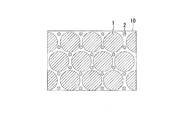
- the laminated molding powder 10 is composed of a coarse-grained inorganic powder 1 and a fine-grained inorganic powder 2 having a particle size smaller than that of the coarse-grained inorganic powder 1.
- the upper limit value and the lower limit value are connected by "-" and displayed in a range, the range including the upper limit value and the lower limit value is meant unless otherwise specified.
- the particle size volume ratio (sometimes referred to as particle size volume ratio) between the coarse-grained inorganic powder 1 and the fine-grained inorganic powder 2 is 28.0 to 53.0.
- a more preferable upper limit of the particle size / volume ratio of the coarse-grained inorganic powder 1 and the fine-grained inorganic powder 2 is 49.6 or less.
- the preferable lower limit of the particle size volume ratio of the coarse-grained inorganic powder 1 and the fine-grained inorganic powder 2 is 28.0 or more, and the more preferable lower limit is 32.0 or more.
- the particle size-volume ratio of the coarse-grained inorganic powder 1 and the fine-grained inorganic powder 2 is less than 28.0, the bearing effect of the fine-grained inorganic powder 2 is not exhibited, so that the concentration of the laminated molding powder 10 in the laminated molding slurry 11 If the value is high, the laminated molding slurry 11 is solidified and thixotropy cannot be obtained.
- the particle size / volume ratio of the coarse-grained inorganic powder 1 and the fine-grained inorganic powder 2 exceeds 53.0, the coarse-grained inorganic powder 1 causes a lot of friction, so that the concentration of the laminated molding powder 10 in the laminated molding slurry 11 If the value is high, the laminated molding slurry 11 is solidified and thixotropy cannot be obtained.
- the particle size volume ratio is the total value obtained by multiplying the volume ratio of each coarse-grained inorganic powder by the average particle size of each coarse-grained inorganic powder, and the volume ratio of each fine-grained inorganic powder is multiplied by the average grain size of each fine-grained inorganic powder.
- the calculation formula is (volume ratio of coarse-grained inorganic powder A ⁇ average particle size of coarse-grained inorganic powder A + volume of coarse-grained inorganic powder B).
- the upper limit of the average particle size of the entire powder for laminated modeling 10 is 20.0 ⁇ m or less.
- the preferable upper limit of the average particle size of the laminated molding powder 10 is 16.0 ⁇ m or less, and more preferably 4.1 ⁇ m or less.
- the lower limit of the average particle size of the laminated molding powder 10 is 2.0 ⁇ m or more.
- the preferable lower limit of the average particle size of the laminated molding powder 10 is 3.0 ⁇ m or more, and more preferably 3.7 ⁇ m or more.
- the particle size is measured by a laser diffraction / scattering method, and the average particle size is d50, that is, the median diameter.
- d50 is a cumulative distribution of 50 vol. In the particle size distribution measured by the laser diffraction / scattering method. The particle size when% is used.
- the d10 of the entire inorganic powder of the laminated modeling powder 10 is 0.2 to 2.0 ⁇ m. More preferably, it is 0.70 to 0.90 ⁇ m.
- the fine inorganic powder 2 is sufficiently present, so that the fine inorganic powder 2 can be evenly distributed around the coarse-grained inorganic powder 1, and the fine inorganic powder 2 can be distributed evenly. Since it functions as a bearing (bearing effect), the viscosity can be lowered even if the concentration of the laminated molding powder 10 in the laminated molding slurry 11 is high.
- d10 is a cumulative distribution of 10 vol. In the particle size distribution measured by the laser diffraction / scattering method. The particle size when% is used.
- the d90 of the entire inorganic powder of the laminated modeling powder 10 is 8 to 30 ⁇ m. More preferably, it is 10 to 15 ⁇ m.
- d90 is a cumulative distribution of 90 vol. In the particle size distribution measured by the laser diffraction / scattering method. The particle size when% is used.
- the volume mixing ratio of the coarse-grained inorganic powder 1 and the fine inorganic powder 2 is preferably 7: 1 to 1: 1.
- the volume mixing ratio is more preferably 6: 1 to 3: 1. More preferably, the volume mixing ratio is 4: 1 to 3: 1. That is, the volume mixing ratio (coarse grain inorganic powder / fine inorganic powder) is preferably 1 to 7.
- the volume mixing ratio is more preferably 3 to 6, still more preferably 3 to 4.
- the lower limit of the volume ratio of the inorganic powder having a particle size of 2.0 ⁇ m or more in the laminated modeling powder 10 is 75.0 vol. % Or more.
- the upper limit of the volume ratio of the inorganic powder having a particle size of 2.0 ⁇ m or more in the laminated molding powder 10 is 85.0 vol. % Or less, more preferably 83.0 vol. % Or less.
- the volume ratio of the inorganic powder having a particle size of 2.0 ⁇ m or more to the laminated molding powder 10 is 75.0 vol. If it is less than%, it becomes difficult to impart thixotropy to the laminated modeling slurry 11 when the concentration of the inorganic powder is increased, which is not preferable.
- the volume ratio of the powder made of alumina in the laminated modeling powder 10 is 5 to 20 vol. It is preferably%.
- the volume ratio of the powder made of alumina is 5 to 20 vol. In the case of%, the bearing effect of the fine powder is improved due to the interaction between alumina and the liquid resin, which is preferable.
- a more preferable upper limit of the volume ratio of the powder made of alumina in the laminated molding powder 10 is 15 vol. % Or less, and a more preferable upper limit is 14 vol. % Or less.
- a more preferable lower limit of the volume ratio of the powder made of alumina in the laminated molding powder 10 is 7 vol. % Or more.
- the shape of the laminated molding powder 10 may be spherical, cubic, flaky, granular, plate-shaped, rod-shaped, needle-shaped, fibrous, lump-shaped, dendritic-shaped, spongy-shaped, or the like.
- the shape of the laminated molding powder 10 is preferably spherical.
- the volume ratio of the spherical powder to the laminated molding powder 10 is 86 vol. If it is% or more, it is possible to suppress an increase in the viscosity of the laminated modeling slurry 11.
- the upper limit of the volume ratio of the spherical powder is not particularly limited, but 100 vol. May be%.
- the mixing method of the coarse-grained inorganic powder 1 and the fine-grained inorganic powder 2 is not particularly limited.
- Examples of the mixing method include a method of dry blending the coarse-grained inorganic powder 1 and the fine-grained inorganic powder 2 and a method of mixing in a liquid resin.
- a method of dry blending a method of manually mixing or a method of using a blender such as a Henschel mixer or a high speed mixer may be used.
- the coarse-grained inorganic powder 1 used in the present invention is composed of at least silica or a compound of silica and alumina.
- silica include crystalline silica, amorphous silica, and fused silica.
- a compound of silica and alumina for example, mullite and the like can be mentioned.
- the coarse-grained inorganic powder 1 is alumina, there is a lot of friction between the coarse-grained inorganic powders 1, and if the concentration of the laminated molding powder 10 in the laminated molding slurry 11 becomes high, the laminated molding slurry 11 solidifies. , Not preferable.
- the upper limit of the average particle size of the coarse-grained inorganic powder 1 is 20.0 ⁇ m or less.
- the preferable upper limit of the average particle size of the laminated molding powder 10 is 16.0 ⁇ m or less, and more preferably 4.1 ⁇ m or less.
- the lower limit of the average particle size of the laminated molding powder 10 is 2.0 ⁇ m or more.
- the preferable lower limit of the average particle size of the laminated molding powder 10 is 3 ⁇ m or more, and more preferably 3.7 ⁇ m or more.
- the ratio d10 / d50 of the coarse-grained inorganic powder 1 to d10 and d50 is preferably 0.1 to 0.7.
- a more preferable upper limit of d10 / d50 is 0.5 or less.
- a more preferable upper limit of d10 / 50 is 0.2 or more.
- the ratio d90 / d50 of the coarse-grained inorganic powder 1 to d90 and d50 is preferably 1.6 to 2.9.
- a more preferable upper limit of d90 / d50 is 2.0 or less.
- a more preferable lower limit of d90 / d50 is 1.7 or more.
- the shape of the powder in the coarse-grained inorganic powder 1 may be spherical, cubic, flaky, granular, plate-shaped, rod-shaped, needle-shaped, fibrous, lump-shaped, dendritic-shaped, spongy-shaped, or the like.
- the shape of the coarse inorganic powder 1 is preferably spherical.
- alumina examples include ⁇ -alumina and ⁇ -alumina.
- ⁇ -alumina is preferable because it is thermally stable.
- alumina is preferable because it easily interacts with the liquid resin and can improve the bearing effect of the coarse-grained inorganic powder 1.
- the average particle size of the fine inorganic powder 2 is 0.10 to 0.64 ⁇ m.
- the average particle size of the fine inorganic powder 2 is less than 0.10 ⁇ m, the fine inorganic powder 2 agglomerates more and the bearing effect is suppressed.
- the average particle size of the fine inorganic powder 2 exceeds 0.64 ⁇ m, the bearing effect is suppressed because the particle size is larger than that of the coarse inorganic powder 1.
- the ratio d10 / d50 of the fine inorganic powder 2 to d10 and d50 is preferably 0.1 to 0.6.
- a more preferable upper limit of d10 / d50 is 0.5 or less.
- the ratio d10 / d50 of the fine inorganic powder 2 to d10 and d50 is within this range, the aggregation of the fine inorganic powder 2 is suppressed in the laminated modeling slurry 11.
- the ratio d90 / d50 of the fine inorganic powder 2 to d90 and d50 is preferably 2.0 to 5.0.
- the ratio d90 / d50 of the fine inorganic powder 2 to d90 / d50 is within this range, the bearing effect of the fine inorganic powder 2 can be improved in the laminated modeling slurry 11.
- the shape of the powder in the fine inorganic powder 2 may be spherical, cubic, flaky, granular, plate-shaped, rod-shaped, needle-shaped, fibrous, lump-shaped, dendritic-shaped, spongy-shaped, or the like. In order to improve the bearing effect of the fine inorganic powder 2, a spherical shape is preferable.
- the laminated modeling slurry 11 is composed of the liquid resin 3 and the above-mentioned laminated modeling powder 10.
- the concentration of the laminated modeling powder 10 in the laminated modeling slurry 11 is 70.0 to 80.0 vol. %.
- the concentration of the laminated modeling powder in the laminated modeling slurry 11 is 70 vol. If it is less than%, the shrinkage rate of the sintered body of the inorganic powder after sintering is large, and cracks may occur in the sintered body having a complicated shape. 80 vol. If it exceeds%, the viscosity becomes too high and the laminated modeling slurry 11 solidifies.
- the liquid resin 3 used in the slurry for laminated modeling 11 is not particularly limited as long as a three-dimensional laminated model can be formed with high accuracy.
- Examples of the liquid resin used in the laminated modeling slurry 11 include a photocurable resin and a thermosetting resin. From the viewpoint of productivity and accuracy of the three-dimensional laminated model, a photocurable resin is preferable.
- Photocuring resin examples of the photocurable resin used in the laminated modeling slurry 11 include radically polymerizable compounds and cationically polymerizable compounds.
- the photocurable resin is cured by irradiating with light in the presence of a photopolymerization initiator.
- the radically polymerizable compound is a compound having an ethylenically unsaturated bond in the molecule.
- the compound having an ethylenically unsaturated bond include methacrylicamide, acrylamide, 2-ethylhexyl acrylate, 2-ethylhexyl methacrylate, lauryl acrylate, lauryl methacrylate, butoxyethyl acrylate, butoxyethyl methacrylate, polypropylene glycol monoacrylate, and polypropylene glycol mono.
- Examples thereof include methacrylate, triethylene glycol diacrylate, triethylene glycol dimethacrylate, tris (2-hydroxyethyl) isocyanurate triacrylate, and tris (2-hydroxyethyl) isocyanurate trimethacrylate.
- These compounds are examples, and are not particularly limited as long as they are compounds that are suitably used for laminated molding. These resins may be used alone or in combination of two or more.
- a cationically polymerizable compound is a compound that initiates polymerization by irradiating with light in the presence of a cationic photopolymerization initiator.
- the cationically polymerizable compound include 3,4-epoxycyclohexylmethyl-3', 4'-epoxycyclohexanecarboxylate, bisphenol A diglycidyl ether, and bisphenol F diglycidyl ether. These compounds are examples, and are not particularly limited as long as they are compounds that are suitably used for laminated modeling. These resins may be used alone or in combination of two or more.
- a radical photopolymerization initiator is used as the photopolymerization initiator.
- a cationic photopolymerization initiator is used as the photopolymerization initiator.
- the radical photopolymerization initiator include acetophenone, anthraquinone, 4,4'-dimethoxybenzoin and the like.
- Cationic photoinitiators are, for example, diphenyliodonium trifluoromethanesulfonic acid, 2- [2- (furan-2-yl) vinyl] -4,6-bis (trichloromethyl) -1,3,5-triazine. , 4-Nitrobenzenediazonium tetrafluoroborate and the like. These compounds are examples, and are not particularly limited as long as they are compounds that are suitably used for laminated modeling.
- the ratio of the photopolymerization initiator to the total of the photocurable resin and the photopolymerization initiator is preferably 0.01 to 8% by mass. If the proportion of the photoinitiator is less than 0.01% by mass, the curing rate will be slow, and it will take time for modeling. When the content ratio of the photoinitiator exceeds 8% by mass, the strength of the three-dimensional laminated model may decrease.
- a polymerization inhibitor, a pigment, a viscosity modifier, or the like may be added to the photocurable resin depending on the purpose.
- the method for producing the laminated modeling slurry 11 is not particularly limited.
- a method for producing the slurry for laminated molding after mixing the powder 10 for laminated molding and the liquid resin 3, the powder 10 for laminated molding is mixed in the liquid resin 3 using a high-speed stirrer, a homogenizer, a planetary mixer, or the like.
- the rotation speed of the high-speed stirrer is preferably 400 to 600 rpm.
- the stirring time is preferably 2 minutes or more. Under these conditions, the laminated molding powder 10 and the liquid resin 3 can be uniformly mixed regardless of the shape of the stirring blade.
- Laminate molding method A typical example of the laminated molding method (FIGS. 4, S2) of the present invention will be described.
- the example described below is an example of the present invention and is not particularly limited.
- the above-mentioned laminated modeling slurry 11 is housed in a container. The bottom of the container can be moved up and down. A thin layer of the laminated modeling slurry 11 is formed on the stored laminated modeling slurry 11 by using a knife edge. The formed thin layer is selectively irradiated with light to cure the laminated modeling slurry 11 to form a cured product having an arbitrary two-dimensional shape.
- the bottom containing the laminated modeling slurry 11 is lowered by a small amount, and the laminated modeling slurry 11 is supplied onto the thin layer on which the cured product having an arbitrary two-dimensional shape is formed, and the knife is again used.
- a thin layer of the laminated modeling slurry 11 is formed at the edge.
- the re-formed thin layer is selectively irradiated with light to form a cured product having an arbitrary two-dimensional shape again.
- a plurality of layers of cured products are laminated to form a three-dimensional laminated model.
- the uncured resin is removed from the obtained three-dimensional laminated model using a cleaning agent or the like.
- the method of selectively irradiating light is not particularly limited as long as a highly accurate three-dimensional laminated model can be obtained.
- a method of reflecting laser light with a polygon mirror and a method of irradiating light from a mask on which a light transmitting portion having an arbitrary pattern is formed.
- FIG. 4 A typical example of the sintering method of the present invention (FIGS. 4 and S3) will be described.
- the three-dimensional laminated model obtained by the laminated modeling method of the present invention is placed in a sintering furnace, and the temperature inside the furnace is raised from room temperature to the degreasing treatment temperature at 1 ° C./hour or higher.
- the degreasing treatment temperature can be appropriately set in the range of, for example, 500 to 700 ° C. When the degreasing treatment temperature is in this temperature range, the resin in the three-dimensional laminated molding can be burned, which is preferable.
- the resin component is burned by heating while maintaining the degreasing treatment temperature for 0.5 to 4 hours (defatting time) (solvent degreasing step).
- the degreasing time can be set according to the type of resin and the ratio of the resin in the laminated model.
- the temperature inside the sintering furnace is raised to the sintering treatment temperature at 50 ° C./hour or higher.
- the sintering treatment temperature can be appropriately set in the range of, for example, 900 to 1300 ° C. When the sintering treatment temperature is within this temperature range, the laminated molding powder 10 can be sintered without cracking, which is preferable.
- the sintering treatment temperature is maintained and heated for 1 to 7 hours (sintering time) to sinter the laminated molding powder 10 (baking). (Conclusion process), a sintered body using the laminated molding powder 10 is obtained.
- the sintering time can be set according to the type of inorganic powder and the like.
- the dilatant fluid refers to a fluid that behaves as a liquid for slow shear stimuli and has a property of exhibiting resistance like a solid for fast shear stimuli.
- the general fluid is a fluid other than thixotropy fluid and dilatant fluid.
- the results of each measurement slurry are shown in FIG.
- the horizontal axis of FIG. 3 shows the mixing ratio of the coarse-grained inorganic powder and the fine-grained inorganic powder, and the vertical axis shows the concentration (vol.%) Of the inorganic powder in the measurement slurry.
- ⁇ means a thixotropy fluid
- ⁇ means a general fluid
- ⁇ means a dilatant fluid (solidified).
- the concentration of the inorganic powder when the concentration of the inorganic powder is low, it is a general fluid, but as the concentration is high, it is found that the thixotropy fluid changes to a dilatant fluid (solidification). It was also found that as the mixing ratio of the fine inorganic powder increased, the thixotropy fluid became a thixotropic fluid on the low concentration side. From the above, it was found that in order to obtain a thixotropy fluid in a state where the concentration of the inorganic powder in the slurry is high, it is necessary to increase the ratio of the coarse-grained inorganic powder to the fine inorganic powder.
- a photocurable acrylic resin which is a liquid resin, is added to the dry-blended inorganic powder so that the concentration of the inorganic powder in the slurry becomes the concentration shown in Tables 2A and 2B, and the mixture is stirred at 400 rpm or more for 25 minutes using a rotary stirrer. Then, a slurry for laminated molding was prepared. The description "-" in the table indicates that it has not been added.
- a laminated model was produced using a general-purpose ultraviolet laser scanning type layered modeling device for the slurry for layered modeling prepared above.
- the wavelength of the laser was 355 to 405 nm, and the output was 1 W or less.
- the environmental temperature at the time of laser irradiation was 25 degrees.
- the uncured resin was removed from the formed laminated model with a cleaning agent containing ethanol.
- the laminated model obtained above is placed in a sintering furnace, the temperature inside the sintering furnace is raised from room temperature to the degreasing treatment temperature (400 to 700 ° C.) at 1 ° C./hour or higher, and the degreasing treatment temperature is 2 I kept the time. Then, the temperature inside the sintering furnace is raised from the degreasing treatment temperature to the sintering treatment temperature (900 to 1300 ° C.) at 50 ° C./hour or higher, and the sintered body is held at the sintering treatment temperature for 2 hours to prepare the sintered body. Obtained.
- Example 5 with the vertical axis representing the particle size volume ratio and the horizontal axis representing the volume mixing ratio (coarse grain inorganic powder / fine inorganic powder).
- ⁇ indicates an example in which the layability was good
- ⁇ indicates a comparative example in which the layability was poor.
- the sintered body was evaluated for Examples 1 and 2 having excellent thixotropy and layability and a powder concentration of 75.0% or more. Both Examples 1 and 2 showed a low shrinkage rate of 5% or less, and in particular, Example 2 showed a lower shrinkage rate than Example 1.
- the laminated modeling powder it is possible to obtain a laminated modeling slurry having good layability and thixotropy even when the concentration of the inorganic powder in the laminated modeling slurry is high. it can.
- the method for producing the slurry for laminated molding, the laminated molding method, and the sintering method of the present invention the three-dimensional laminated molded body having a more complicated shape than the case of molding by injection and after the sintering treatment. It is possible to form a sintered body having a low shrinkage rate.
Abstract
積層造形用粉末(10)は、粗粒無機粉末(1)と、平均粒径が粗粒無機粉末(1)より小さい微細無機粉末(2)と、からなり、粗粒無機粉末(1)と微細無機粉末(2)との粒径体積比率が28.0~53.0である。
Description
本発明は、積層造形用粉末、積層造形用スラリー、3次元積層造形体、焼結体、積層造形用スラリーの製造方法、積層造形方法及び焼結方法に関する。
本願は、2019年7月4日に、日本に出願された特願2019-125452号に基づき優先権を主張し、その内容をここに援用する。
本願は、2019年7月4日に、日本に出願された特願2019-125452号に基づき優先権を主張し、その内容をここに援用する。
航空機用のタービン翼やガスタービンは、精密鋳造によって製造される。タービン等の内部構造の形成には、セラミックス中子が用いられる。ガスタービンやエンジンの高効率化のために、内部構造を決定するセラミックス中子には、より複雑な形状が求められるようになっている。
セラミックス中子を製造する方法については、例えば、特許文献1に開示されている方法がある。当該方法では、ワックスを金型に射出してろう型を作製し、その後、無機粒子を含有するスラリー中に作製したろう型を浸漬させてコーティングし、乾燥することで乾燥鋳型を形成している。
しかし、特許文献1に開示されたスラリーを用いた方法では、射出成型を用いているため、型抜き対策などの制約があり、複雑な形状の中子を製造しにくいという問題がある。
一方、型抜きなどの制約を受けないで精密な成型体を形成する手法として、3次元の任意の形状を形成することができる3次元積層造形技術が知られている。3次元積層造形技術としては、シート積層法、光造形法、インクジェット法、選択的レーザー焼結法、レーザー直接積層法、溶融物堆積法などがある。中でも、光硬化樹脂にレーザー光を照射して硬化させることで立体物を形成する光造形法は、造形速度が速く、高精度という利点を有しているため、生産性の観点で好ましい。
セラミックスの3次元積層造形体を形成する光造形法として、液状の光硬化樹脂とセラミックス粉末(無機粉末)とを混合したスラリーに光を照射し、セラミックスの3次元積層造形を形成する方法がある。このように形成した3次元積層造形体に対し、光硬化樹脂を燃焼させる脱脂処理、無機粉末を焼結する焼結処理を行うことで焼結体を得ることができる。
積層造形用のスラリー中の無機粉末の濃度が高くなるほど、脱脂処理で焼失する光硬化樹脂の量が少なくなる。そのため、積層造形用のスラリー中の無機粉末の濃度が高くなるほど、焼結体の収縮率が低くなる。セラミックス焼結体の収縮率が低くなれば、焼結処理後の焼結体のひび割れ等が発生しなくなるため、無機粉末をできる限り高濃度にすることが求められている。
しかし、無機粉末の濃度が高くなると、積層造形用スラリーの粘度が高くなり、良好な敷設性が得られなくなる。ここで、良好な敷設性とは、積層造形用スラリーを塗布した際に均一に薄く広がる事をいう。光造形法で積層造形体を作成する際に、積層造形用スラリーの塗布面が不均一であると、光硬化樹脂を硬化した後の形状がいびつになり、光造形法の高精度という利点が生かせなくなる。そのため、積層造形用スラリーには、無機粉末の濃度が高いことに加え、良好な敷設性が求められる。
また、積層造形用スラリーは、塗布後厚さが変わらないことが求められる。光照射工程において、振動などの外的影響などでスラリーの厚さが変化すると、硬化した樹脂の厚さも変わることになる。そのため、積層造形用スラリーには、塗布時は流動し、塗布後は流動しなくなるチクソトロピー性を有することが求められる。ここで、チクソトロピー性とは、せん断応力が負荷されると粘度が低下し、せん断応力が除荷され静止状態となると次第に粘度が上昇し、ゲル状になる性質をいう。
本発明は、上述の問題を解決するためになされたものであり、その課題は、積層造形用スラリー中の無機粉末の濃度が高い場合であっても、積層造形用スラリーが良好な敷設性、チクソトロピー性を有することができる積層造形用粉末を提供することにある。また、本発明のもう一つの課題は、射出で成型した場合よりも複雑な形状の3次元積層造形体及び焼結処理後の収縮率が低い焼結体を形成することができる、積層造形用スラリー、積層造形用スラリーの製造方法、積層造形方法、焼結方法を提供することにある。
前記課題を解決するために、本発明は以下の手段を提案している。
(1)本発明の一態様に係る積層造形用粉末は、粗粒無機粉末と、平均粒径が前記粗粒無機粉末より小さい微細無機粉末と、からなり、前記粗粒無機粉末と前記微細無機粉末との粒径体積比率が28.0~53.0である。
(2)(1)に記載の積層造形用粉末は、前記粗粒無機粉末の平均粒径は2.0~20.0μmであり、前記微細無機粉末の平均粒径は0.10~0.64μmであってもよい。
(3)(1)~(2)のいずれか一態様に記載の積層造形用粉末は、前記粒径体積比率が28.0~49.6であるであってもよい。
(4)(1)~(3)のいずれか一態様に記載の積層造形用粉末は、前記粗粒無機粉末のd10とd50との比d10/d50が、0.1~0.7であり、前記粗粒無機粉末のd90とd50との比d90/d50が、1.6~2.9であってもよい。
(5)(1)~(4)のいずれか一態様に記載の積層造形用粉末は、前記微細無機粉末のd10とd50との比d10/d50が、0.1~0.6であり、前記微細無機粉末のd90とd50との比d90/d50が、2.0~5.0であってもよい。
(6)(1)~(5)のいずれか一態様に記載の積層造形用粉末は、前記粗粒無機粉末が少なくともシリカ又はシリカとアルミナとの化合物のいずれか一方であってもよい。
(7)(1)~(6)のいずれか一態様に記載の積層造形用粉末は、前記微細無機粉末が少なくともシリカ又はアルミナのいずれか一方であってもよい。
(8)(1)~(7)のいずれか一態様に記載の積層造形用粉末は、前記粗粒無機粉末の形状が球状であってもよい。
(9)(1)~(8)のいずれか一態様に記載の積層造形用粉末は、前記微細無機粉末の形状が球状であってもよい。
(10)本発明の別の一態様に記載の積層造形用粉末は、d10が0.1~2.0μm、d50が3.0~20μm、d90が10~30μmである無機粉末からなり、前記無機粉末における粒径2.0μm以上の無機粉末の体積割合が75.0~85.0vol.%である。
(11)(10)に記載の積層造形用粉末は、前記無機粉末のアルミナからなる粉末の体積割合が5~20vol.%であってもよい。
(12)(10)又は(11)に記載の積層造形用粉末は、前記無機粉末に占める球状の粉末の体積割合が86vol.%以上であってもよい。
(13)本発明の一態様に係る積層造形用スラリーは、(1)~(12)いずれか一態様に記載の積層造形用粉末と液状樹脂とからなる積層造形用スラリーにおいて、積層造形用粉末の濃度が70.0~80.0vol.%である。
(14)本発明の一態様に係る3次元積層造形体は、(1)~(12)いずれか一態様に記載の積層造形用粉末を用いる。
(15)本発明の一態様に係る焼結体は、(1)~(12)いずれか一態様に記載の積層造形用粉末を用いる。
(16)本発明の一態様に係る積層造形用スラリーの製造方法は、(1)~(12)いずれか一態様に記載の積層造形用粉末と液状樹脂とを混合し、400~600rpmで攪拌する。
(17)本発明の一態様に係る積層造形方法は、(13)に記載の積層造形用スラリーを用いて3次元積層造形体を形成する。
(18)本発明の一態様に係る焼結方法は、(17)に記載の積層造形方法で形成された3次元積層造形体に、脱脂処理、焼結処理を行う。
本発明の一態様に係る積層造形用粉末によれば、積層造形用スラリー中の無機粉末の濃度が高い場合であっても、良好な敷設性、チクソトロピー性を有する積層造形用スラリーを得ることができる。また、本発明の積層造形用スラリー、積層造形用スラリーの製造方法、積層造形方法、焼結方法によれば、射出で成型した場合よりも複雑な形状の3次元積層造形体及び焼結処理後の収縮率が低い焼結体を形成することができる。
[積層造形用粉末]
以下、図面を参照し、本発明の一実施形態に係る積層造形用粉末を説明する。
本実施形態に係る積層造形用粉末10は、図1に示すように粗粒無機粉末1及び粗粒無機粉末1より粒径が小さい微細無機粉末2から構成される。なお、以下の説明で上限値と下限値を「~」で結んで範囲表示する場合、特に注釈しない限り、上限値と下限値を含む範囲を意味する。
以下、図面を参照し、本発明の一実施形態に係る積層造形用粉末を説明する。
本実施形態に係る積層造形用粉末10は、図1に示すように粗粒無機粉末1及び粗粒無機粉末1より粒径が小さい微細無機粉末2から構成される。なお、以下の説明で上限値と下限値を「~」で結んで範囲表示する場合、特に注釈しない限り、上限値と下限値を含む範囲を意味する。
粗粒無機粉末1と微細無機粉末2との粒径体積比率(粒径体積比と称する場合がある)は、28.0~53.0である。粗粒無機粉末1と微細無機粉末2との粒径体積比率のより好ましい上限は、49.6以下である。粗粒無機粉末1と微細無機粉末2との粒径体積比率の好ましい下限は、28.0以上であり、より好ましい下限は、32.0以上である。粗粒無機粉末1と微細無機粉末2との粒径体積比率が28.0未満であると微細無機粉末2のベアリング効果が発揮されないため、積層造形用スラリー11中の積層造形用粉末10の濃度が高い場合、積層造形用スラリー11が固化し、チクソトロピー性が得られない。粗粒無機粉末1と微細無機粉末2との粒径体積比率が53.0超の場合、粗粒無機粉末1の摩擦が多く起こるため、積層造形用スラリー11中の積層造形用粉末10の濃度が高い場合、積層造形用スラリー11が固化し、チクソトロピー性が得られない。ここで、粒径体積比率とは、各粗粒無機粉末の体積割合に各粗粒無機粉末の平均粒径を乗じたものの合計値を各微細無機粉末の体積割合に各微細無機粉末の平均粒径を乗じたものの合計値で除した値をいう。例えば、粗粒無機粉末A及びBと微細無機粉末a及びbの場合の計算式は、(粗粒無機粉末Aの体積割合×粗粒無機粉末Aの平均粒径+粗粒無機粉末Bの体積割合×粗粒無機粉末Bの平均粒径)/(微細無機粉末aの体積割合×微細無機粉末aの平均粒径+微細無機粉末bの体積割合×微細無機粉末bの平均粒径)となる。
積層造形用粉末10の粉末全体の平均粒径の上限は20.0μm以下である。積層造形用粉末10の平均粒径の好ましい上限は、16.0μm以下であり、より好ましくは4.1μm以下である。積層造形用粉末10の平均粒径の下限は2.0μm以上である。積層造形用粉末10の平均粒径の好ましい下限は3.0μm以上であり、より好ましくは3,7μm以上である。積層造形用粉末10の平均粒径が2.0~20.0μmの範囲であれば、積層造形用スラリー11中で積層造形用粉末10が沈降しないため、好ましい。なお、ここで粒径は、レーザー回折・散乱法で測定され、平均粒径はd50、すなわちメジアン径を言う。d50とは、レーザー回折・散乱法で測定された粒度分布において、累積分布50vol.%のときの粒径を言う。
積層造形用粉末10の無機粉末全体のd10は0.2~2.0μmである。より好ましくは、0.70~0.90μmである。積層造形用粉末10のd10がこの範囲であると、微細無機粉末2が十分にあるため、粗粒無機粉末1の周辺に微細無機粉末2が均等に分布でき、また、この微細無機粉末2がベアリングとして機能するため(ベアリング効果)、積層造形用スラリー11中の積層造形用粉末10の濃度が高濃度でも粘度を下げることができる。ここで、d10とは、レーザー回折・散乱法で測定された粒度分布において、累積分布10vol.%のときの粒径を言う。
積層造形用粉末10の無機粉末全体のd90は8~30μmである。より好ましくは、10~15μmである。積層造形用粉末10のd90がこの範囲内であると、積層造形用スラリー11中の粗粒無機粉末1が沈降せず、積層造形用スラリー11の安定性が向上するため、好ましい。ここで、d90とは、レーザー回折・散乱法で測定された粒度分布において、累積分布90vol.%のときの粒径を言う。
積層造形用粉末10において、粗粒無機粉末1と微細無機粉末2との体積混合比は、7:1~1:1が好ましい。体積混合比はより好ましくは、6:1~3:1である。さらに好ましくは体積混合比は4:1~3:1である。即ち体積混合比(粗粒無機粉末/微細無機粉末)は、1~7が好ましい。体積混合比は、より好ましくは、3~6であり、さらに好ましくは3~4である。粗粒無機粉末1と微細無機粉末2との体積混合比がこの範囲であると、積層造形用スラリー11に対し、チクソトロピー性を付与しつつ、良好な敷設性を得ることができる。
積層造形用粉末10に占める粒径2.0μm以上の無機粉末の体積割合の下限は75.0vol.%以上である。積層造形用粉末10に占める粒径2.0μm以上の無機粉末の体積割合の上限は85.0vol.%以下であり、より好ましくは83.0vol.%以下である。積層造形用粉末10に占める粒径2.0μm以上の無機粉末の体積割合が85.0%よりも大きい場合、液状樹脂3との関係で粗粒無機粉末1との摩擦が多く起こり、微細粉末によるベアリング効果があっても粘度を下げることができないため、好ましくない。積層造形用粉末10に占める粒径2.0μm以上の無機粉末の体積割合が75.0vol.%未満になると、積層造形用スラリー11に対し、無機粉末の濃度を高濃度にした場合にチクソトロピー性を付与しにくくなるため、好ましくない。
積層造形用粉末10中のアルミナからなる粉末の体積割合は5~20vol.%である事が好ましい。アルミナからなる粉末の体積割合が、5~20vol.%の場合、アルミナと液状樹脂との相互作用の関係から、微細粉末のベアリング効果が向上するため、好ましい。積層造形用粉末10中のアルミナからなる粉末の体積割合のより好ましい上限は、15vol.%以下であり、さらに好ましい上限は14vol.%以下である。積層造形用粉末10中のアルミナからなる粉末の体積割合のより好ましい下限は7vol.%以上である。
積層造形用粉末10の形状は、球状、立方体状、片状、粒状、板状、棒状、針状、繊維状、塊状、樹枝状、海綿状などであってもよい。微細無機粉末2のベアリング効果を向上するためには、積層造形用粉末10の形状は、球状が好ましい。積層造形用粉末10に占める球状の粉末の体積割合が86vol.%以上であれば、積層造形用スラリー11の粘度の上昇を抑制することができる。球状の粉末の体積割合の上限値は特に限定されないが、100vol.%であってもよい。
粗粒無機粉末1と微細無機粉末2との混合方法は特に限定されない。混合方法としては、例えば、粗粒無機粉末1と微細無機粉末2とをドライブレンドする方法や液状樹脂中で混合する方法が挙げられる。ドライブレンドする方法としては、手動で混合する方法でもよいし、ヘンシェルミキサー、ハイスピードミキサーなどのブレンダーを使用する方法でもよい。
[粗粒無機粉末]
本発明に使用する粗粒無機粉末1は、少なくともシリカ又はシリカとアルミナとの化合物のいずれか一方からなる。シリカの例としては、例えば、結晶シリカ、アモルファスシリカ、溶融シリカなどを挙げることができる。また、シリカとアルミナとの化合物としては、例えば、ムライトなどを挙げることができる。粗粒無機粉末1がアルミナである場合、粗粒無機粉末1同士の摩擦が多く、積層造形用スラリー11中の積層造形用粉末10の濃度が高くなると積層造形用スラリー11が固化してしまうため、好ましくない。
本発明に使用する粗粒無機粉末1は、少なくともシリカ又はシリカとアルミナとの化合物のいずれか一方からなる。シリカの例としては、例えば、結晶シリカ、アモルファスシリカ、溶融シリカなどを挙げることができる。また、シリカとアルミナとの化合物としては、例えば、ムライトなどを挙げることができる。粗粒無機粉末1がアルミナである場合、粗粒無機粉末1同士の摩擦が多く、積層造形用スラリー11中の積層造形用粉末10の濃度が高くなると積層造形用スラリー11が固化してしまうため、好ましくない。
粗粒無機粉末1の平均粒径の上限は20.0μm以下である。積層造形用粉末10の平均粒径の好ましい上限は、16.0μm以下であり、より好ましくは4.1μm以下である。積層造形用粉末10の平均粒径の下限は2.0μm以上である。積層造形用粉末10の平均粒径の好ましい下限は3μm以上であり、より好ましくは3,7μm以上である。積層造形用粉末10の平均粒径が2.0~20.0μmの範囲であれば、積層造形用スラリー11中で積層造形用粉末10が沈降しないため、好ましい。
粗粒無機粉末1のd10とd50との比d10/d50が、0.1~0.7である事が好ましい。d10/d50のより好ましい上限は0.5以下である。d10/50のさらに好ましい上限は、0.2以上である。粗粒無機粉末1のd10とd50との比d10/d50がこの範囲であれば、積層造形用スラリー11中において粗粒無機粉末1同士の摩擦を抑制することができる。
粗粒無機粉末1のd90とd50との比d90/d50が、1.6~2.9であることが好ましい。d90/d50のより好ましい上限は、2.0以下である。d90/d50のより好ましい下限は、1.7以上である。粗粒無機粉末1のd90とd50との比d90/d50がこの範囲であれば、積層造形用スラリー11中において、粗粒無機粉末1の沈降を抑制することができる。
粗粒無機粉末1中の粉末の形状は、球状、立方体状、片状、粒状、板状、棒状、針状、繊維状、塊状、樹枝状、海綿状などであってもよい。微細無機粉末2のベアリング効果を向上するためには、粗粒無機粉末1の形状は球状が好ましい。
[微細無機粉末]
本発明に使用する微細無機粉末2は、少なくともシリカ又はアルミナのいずれか一方を用いることができる。アルミナは、例えば、αーアルミナ、γ―アルミナを挙げることができる。特にα―アルミナが熱的に安定であるため、好ましい。また、アルミナは、液状樹脂との間に相互作用が働きやすく、粗粒無機粉末1のベアリング効果を向上することができるため、好ましい。
本発明に使用する微細無機粉末2は、少なくともシリカ又はアルミナのいずれか一方を用いることができる。アルミナは、例えば、αーアルミナ、γ―アルミナを挙げることができる。特にα―アルミナが熱的に安定であるため、好ましい。また、アルミナは、液状樹脂との間に相互作用が働きやすく、粗粒無機粉末1のベアリング効果を向上することができるため、好ましい。
微細無機粉末2の平均粒径は、0.10~0.64μmである。微細無機粉末2の平均粒径が0.10μm未満であると、微細無機粉末2同士の凝集が多くなり、ベアリング効果が抑制される。微細無機粉末2の平均粒径が0.64μm超では、粗粒無機粉末1に対し、粒径が大きいため、ベアリング効果が抑制される。
微細無機粉末2のd10とd50との比d10/d50が、0.1~0.6である事が好ましい。d10/d50のより好ましい上限は、0.5以下である。微細無機粉末2のd10とd50との比d10/d50がこの範囲であれば、積層造形用スラリー11中において微細無機粉末2同士の凝集が抑制される。
微細無機粉末2のd90とd50との比d90/d50が、2.0~5.0であることが好ましい。微細無機粉末2のd90とd50との比d90/d50がこの範囲であれば、積層造形用スラリー11中において微細無機粉末2のベアリング効果を向上することができる。
微細無機粉末2中の粉末の形状は、球状、立方体状、片状、粒状、板状、棒状、針状、繊維状、塊状、樹枝状、海綿状などであってもよい。微細無機粉末2のベアリング効果を向上するためには、球状が好ましい。
[積層造形用スラリー]
図2に示すように、積層造形用スラリー11は液状樹脂3と上述の積層造形用粉末10とから構成される。積層造形用スラリー11中の積層造形用粉末10の濃度は70.0~80.0vol.%である。積層造形用スラリー11中の積層造形用粉末の濃度が70vol.%未満の場合、焼結後の無機粉末の焼結体の収縮率が大きく、複雑な形状の焼結体においてひびが入ることがある。80vol.%超の場合、粘度が高くなりすぎて積層造形用スラリー11が固化してしまう。
図2に示すように、積層造形用スラリー11は液状樹脂3と上述の積層造形用粉末10とから構成される。積層造形用スラリー11中の積層造形用粉末10の濃度は70.0~80.0vol.%である。積層造形用スラリー11中の積層造形用粉末の濃度が70vol.%未満の場合、焼結後の無機粉末の焼結体の収縮率が大きく、複雑な形状の焼結体においてひびが入ることがある。80vol.%超の場合、粘度が高くなりすぎて積層造形用スラリー11が固化してしまう。
[液状樹脂]
積層造形用スラリー11に用いられる液状樹脂3としては、3次元の積層造形体を高精度で形成することができれば、特に限定されない。積層造形用スラリー11に用いられる液状樹脂としては、例えば、光硬化樹脂、熱硬化樹脂などを挙げることができる。生産性や3次元積層造形体の精度の観点からは、光硬化樹脂が好ましい。
積層造形用スラリー11に用いられる液状樹脂3としては、3次元の積層造形体を高精度で形成することができれば、特に限定されない。積層造形用スラリー11に用いられる液状樹脂としては、例えば、光硬化樹脂、熱硬化樹脂などを挙げることができる。生産性や3次元積層造形体の精度の観点からは、光硬化樹脂が好ましい。
[光硬化樹脂]
積層造形用スラリー11に用いられる光硬化樹脂としては、例えば、ラジカル重合性の化合物やカチオン重合性の化合物が挙げられる。光硬化樹脂は、光重合開始剤の存在下で光を照射することで硬化する。
積層造形用スラリー11に用いられる光硬化樹脂としては、例えば、ラジカル重合性の化合物やカチオン重合性の化合物が挙げられる。光硬化樹脂は、光重合開始剤の存在下で光を照射することで硬化する。
ラジカル重合性化合物は、エチレン性不飽和結合を分子中に有する化合物である。エチレン性不飽和結合を有する化合物としては、例えば、メタクリルアミド、アクリルアミド、2-エチルヘキシルアクリレート、2-エチルヘキシルメタクリレート、ラウリルアクリレート、ラウリルメタクリレート、ブトキシエチルアクリレート、ブトキシエチルメタクリレート、ポリプロピレングリコールモノアクリレート、ポリプロピレングリコールモノメタクリレート、トリエチレングリコールジアクリレート、トリエチレングリコールジメタクリレート、トリス(2-ヒドロキシエチル)イソシアヌレートトリアクリレート、トリス(2-ヒドロキシエチル)イソシアヌレートトリメタクリレートなどが挙げられる。これらの化合物は一例であり、積層造形に好適に用いられる化合物であれば特に限定されない。これらの樹脂は、単独又は2種以上を組み合わせてもよい。
カチオン重合性化合物は、カチオン性光重合開始剤の存在下で光を照射することで重合を開始する化合物である。カチオン重合性化合物としては、3,4-エポキシシクロヘキシルメチル―3‘、4‘-エポキシシクロヘキサンカルボキシレート、ビスフェノールAジグリシジルエーテル、ビスフェノールFジグリシジルエーテルなどが挙げられる。これらの化合物は一例であり、積層造形に好適に用いられる化合物であれば特に限定されない。これらの樹脂は、単独又は2種以上を組み合わせてもよい。
光硬化樹脂としてラジカル重合性化合物を用いる場合は、光重合開始剤はラジカル性の光重合開始剤を用いる。光硬化樹脂としてカチオン重合性化合物を用いる場合は、光重合開始剤はカチオン性の光重合開始剤を用いる。ラジカル性の光重合開始剤は、例えば、アセトフェノン、アントラキノン、4,4‘-ジメトキシベンゾインなどが挙げられる。カチオン性の光重合開始剤は、例えば、ジフェニルヨードニウムトリフルオロメタンスルホン酸、2-[2-(フラン-2-イル)ビニル]-4,6-ビス(トリクロロメチル)-1,3,5-トリアジン、4-ニトロベンゼンジアゾニウムテトラフルオロボラートなどが挙げられる。これらの化合物は一例であり、積層造形に好適に用いられる化合物であれば特に限定されない。
光硬化樹脂と光重合開始剤との合計に対する光重合開始剤の割合は、0.01~8質量%であることが好ましい。光開始剤の割合が0.01質量%未満の場合は、硬化速度が遅くなるため、造形に時間が必要になる。光開始剤の含有割合が8質量%超の場合、3次元積層造形体の強度が低下する場合がある。その他、目的に応じ、光硬化樹脂に重合禁止剤、顔料、粘度調整剤などを添加してもよい。
[積層造形用スラリーの製造方法]
積層造形用スラリー11を製造するための方法(図4、S1)は特に限定されない。積層造形用スラリーを製造するための方法としては、積層造形用粉末10と液状樹脂3とを混合後、高速撹拌機、ホモジナイザー、プラネタリ―ミキサーなどを用いて積層造形用粉末10を液状樹脂3中に分散する方法がある。例えば、高速撹拌機の回転数は、400~600rpmが好ましい。この攪拌速度の範囲で攪拌を行うことで、積層造形用粉末10と液状樹脂3とを均一に混合することができる。攪拌時間は、2分以上が好ましい。これらの条件であれば攪拌翼の形状によらず、積層造形用粉末10と液状樹脂3とを均一に混合することができる。
積層造形用スラリー11を製造するための方法(図4、S1)は特に限定されない。積層造形用スラリーを製造するための方法としては、積層造形用粉末10と液状樹脂3とを混合後、高速撹拌機、ホモジナイザー、プラネタリ―ミキサーなどを用いて積層造形用粉末10を液状樹脂3中に分散する方法がある。例えば、高速撹拌機の回転数は、400~600rpmが好ましい。この攪拌速度の範囲で攪拌を行うことで、積層造形用粉末10と液状樹脂3とを均一に混合することができる。攪拌時間は、2分以上が好ましい。これらの条件であれば攪拌翼の形状によらず、積層造形用粉末10と液状樹脂3とを均一に混合することができる。
[積層造形方法]
本発明の積層造形方法(図4、S2)の代表的な例を説明する。下記に説明する例は本発明の一例であり、特に限定はされない。
上記の積層造形用スラリー11を容器に収容する。容器の底は、上下に可動することができる。収容された積層造形用スラリー11に対し、ナイフエッジを用い積層造形用スラリー11の薄層を形成する。形成された薄層に、選択的に光を照射して積層造形用スラリー11を硬化させて、任意の2次元形状の硬化物を形成する。
次に、積層造形用スラリー11が収容された底を微小量降下させて、この任意の2次元形状の硬化物が形成された薄層の上に、積層造形用スラリー11を供給し、再度ナイフエッジで積層造形用スラリー11の薄層を形成する。この再度形成された薄層に対して選択的に光を照射し、再度任意の2次元形状の硬化物を形成する。これらの工程を繰り返すことで、複数層の硬化物が積層されて3次元の積層造形体が形成される。得られた3次元の積層造形体は、洗浄剤等を用いて未硬化の樹脂を除去する。
光を選択的に照射する方法としては、高精度な3次元の積層造形体を得られれば特に限定されない。例えば、レーザー光をポリゴンミラーで反射させる方法や、任意のパターンの光透過部が形成されたマスクの上から光を照射する方法などがある。
[焼結方法]
本発明の焼結方法(図4、S3)の代表的な例を説明する。本発明の積層造形方法で得られた3次元の積層造形体を焼結炉に入れ、1℃/時間以上で室温から脱脂処理温度まで炉内の温度を昇温する。脱脂処理温度は、例えば、500~700℃の範囲で適宜設定することができる。脱脂処理温度がこの温度範囲であれば、3次元積層造形中の樹脂を燃焼させることができるので、好ましい。脱脂処理温度まで焼結炉内の温度が到達した後は、0.5~4時間(脱脂時間)、その脱脂処理温度を保持して加熱し、樹脂成分を燃焼させる(脱脂工程)。脱脂時間は、樹脂の種類や積層造形体中の樹脂比率に応じて設定することができる。
次に、50℃/時間以上で焼結処理温度まで焼結炉の炉内の温度を昇温する。焼結処理温度は、例えば900~1300℃の範囲で適宜設定することができる。焼結処理温度がこの温度範囲であれば、積層造形用粉末10をひびなどが入らずに焼結させることができるので、好ましい。焼結処理温度まで炉内の温度が到達した後は、その焼結処理温度を保持して、1~7時間(焼結時間)加熱し、積層造形用粉末10を焼結させることで(焼結工程)、積層造形用粉末10を用いた焼結体が得られる。焼結時間は、無機粉末の種類などに応じて設定することができる。
以下、実施例にて、本発明の具体的態様を説明するが、本発明は以下の態様に限定されるものではない。
[粗粒粉末と微細粉末との比率とチクソトロピー性との関係確認実験]
粗粒無機粉末として、表1の粗粒無機粉末1(SiO2、球状、平均粒径5.0μm)を用い、微細無機粉末として、表1の微細無機粉末1(SiO2、球状、平均粒径0.64μm)を用いた。粗粒無機粉末と微細無機粉末を4:0~0:4の混合比でドライブレンドした。その後、無機粉末の濃度が30~80vol.%になるようにドライブレンド後の無機粉末に液状樹脂を加え、高速撹拌機を用い400~600rpmで25分攪拌し、測定用スラリーを作製した。
粗粒無機粉末として、表1の粗粒無機粉末1(SiO2、球状、平均粒径5.0μm)を用い、微細無機粉末として、表1の微細無機粉末1(SiO2、球状、平均粒径0.64μm)を用いた。粗粒無機粉末と微細無機粉末を4:0~0:4の混合比でドライブレンドした。その後、無機粉末の濃度が30~80vol.%になるようにドライブレンド後の無機粉末に液状樹脂を加え、高速撹拌機を用い400~600rpmで25分攪拌し、測定用スラリーを作製した。
コーンプレート型動粘度計で、せん断速度を0/sから25/sと上昇させた場合の、10/sのせん断速度時のせん断応力A(Pa)と、せん断速度を25/sから0/sと減少させた場合の、10/sのせん断速度時のせん断応力B(Pa)とを比較して、両者の大小より作製した測定用スラリーのチクソトロピー性の性質評価を実施した。その比A/B>1のときをチクソトロピー流体、A/B=1のときを一般流体、A/B<1のときを固化又はダイラタント流体と判定した。ここで、ダイラタント流体とは、遅いせん断刺激には液体用にふるまい、速いせん断刺激には固体のように抵抗力を発揮する性質を有する流体をいう。一般流体は、ここではチクソトロピー流体、ダイラタント流体以外の流体とした。各測定用スラリーの結果を図3に示す。図3の横軸は、粗粒無機粉末と微細無機粉末の混合比を示し、縦軸は、測定用スラリー中の無機粉末の濃度(vol.%)を示す。図3中の〇は、チクソトロピー流体、△は、一般流体、×は、ダイラタント流体(固化)であったことを意味する。
図3に示すように、無機粉末の濃度が低いときは、一般流体であるが、濃度が高くなるにつれて、チクソトロピー流体からダイラタント流体(固化)に変化することが分かった。また、微細無機粉末の混合比が高くなるにつれて、低濃度側でチクソトロピー流体となることが分かった。以上のことから、スラリー中の無機粉末の濃度が高い状態でチクソトロピー流体を得るためには、粗粒無機粉末の比率を微細無機粉末に対して高くする必要がある事が分かった。
[積層造形用スラリーの作製]
上記知見を基に、表1に記載の粗粒無機粉末と微細無機粉末を表2A及び表2Bに記載の体積混合比(粗粒無機粉末/微細無機粉末)でドライブレンドした。なお、表2A中の各無機粉末の体積割合は、液状樹脂と無機粉末の合計体積に対する無機粉末の体積割合を示す。スラリー中の無機粉末の濃度が表2A及び表2Bに記載の濃度になるように液状樹脂である光硬化性アクリル樹脂をドライブレンド後の無機粉末に加え、回転攪拌機を用い400rpm以上で25分攪拌し、積層造形用スラリーを作製した。表中の記載「―」は、添加されていないことを示す。
上記知見を基に、表1に記載の粗粒無機粉末と微細無機粉末を表2A及び表2Bに記載の体積混合比(粗粒無機粉末/微細無機粉末)でドライブレンドした。なお、表2A中の各無機粉末の体積割合は、液状樹脂と無機粉末の合計体積に対する無機粉末の体積割合を示す。スラリー中の無機粉末の濃度が表2A及び表2Bに記載の濃度になるように液状樹脂である光硬化性アクリル樹脂をドライブレンド後の無機粉末に加え、回転攪拌機を用い400rpm以上で25分攪拌し、積層造形用スラリーを作製した。表中の記載「―」は、添加されていないことを示す。


[積層造形体の作製]
上記で作成した積層造形用スラリーに対して、汎用型の紫外線レーザー走査型の積層造形装置を用い、積層造形体を作製した。レーザの波長は355~405nm、出力は1W以下とした。レーザ照射時の環境温度は25度とした。形成された積層造形体は、エタノールを含有する洗浄剤で未硬化の樹脂を取り除いた。
上記で作成した積層造形用スラリーに対して、汎用型の紫外線レーザー走査型の積層造形装置を用い、積層造形体を作製した。レーザの波長は355~405nm、出力は1W以下とした。レーザ照射時の環境温度は25度とした。形成された積層造形体は、エタノールを含有する洗浄剤で未硬化の樹脂を取り除いた。
[焼結体の作製]
上記で得られた積層造形体を焼結炉に入れ、1℃/時間以上で室温から脱脂処理温度(400~700℃)まで焼結炉内の温度を昇温し、その脱脂処理温度で2時間保持した。その後、50℃/時間以上で脱脂処理温度から焼結処理温度(900~1300℃)まで焼結炉内の温度を昇温し、その焼結処理温度で2時間保持して、焼結体を得た。
上記で得られた積層造形体を焼結炉に入れ、1℃/時間以上で室温から脱脂処理温度(400~700℃)まで焼結炉内の温度を昇温し、その脱脂処理温度で2時間保持した。その後、50℃/時間以上で脱脂処理温度から焼結処理温度(900~1300℃)まで焼結炉内の温度を昇温し、その焼結処理温度で2時間保持して、焼結体を得た。
[積層造形用粉末の粒度分布測定]
表2に記載の割合で粗粒無機粉末と微細無機粉末とをドライブレンドして作製した積層造形用粉末約1gを容器に入れ、レーザ回折式計測装置:マスターサイザーを用いて、d10、d50、d90を測定した。測定の結果を表3に示す。なお、表2中の粒径2.0μm以上の無機粉末の体積割合は、測定して得られた各粉末の粒度分布から計算して求めた。
表2に記載の割合で粗粒無機粉末と微細無機粉末とをドライブレンドして作製した積層造形用粉末約1gを容器に入れ、レーザ回折式計測装置:マスターサイザーを用いて、d10、d50、d90を測定した。測定の結果を表3に示す。なお、表2中の粒径2.0μm以上の無機粉末の体積割合は、測定して得られた各粉末の粒度分布から計算して求めた。
[積層造形用スラリーの敷設性及びチクソトロピー性測定]
敷設性の評価は、ステンレス製スキージングブレードを用いて、敷設速度5mm/sの範囲の一定速度で、厚さ100μmの均一なスラリー層を敷設できるかどうかにて評価した。均一なスラリーができる場合を合格とし、ムラや気泡ができる場合を不合格とした。
コーンプレート型動粘度計を用い、上記積層造形用スラリーの粘度ηa1を測定した(室温、せん断速度0~25/s)。
コーンプレート型動粘度計において、せん断速度を0/sから25/sと上昇させた場合の、10/sのせん断速度時のせん断応力A(Pa)と、せん断速度を25/sから0/sと減少させた場合の、10/sのせん断速度時のせん断応力B(Pa)とを比較することで、測定用スラリーのチクソトロピー性を評価した。A/B>1のときを合格とし、A/B≦1のときは不合格とした。得られた結果を表3に示す。表中の〇は合格を示し、×は不合格を示す。
[焼結体評価]
焼結体の評価は、脱脂処理前の積層造形体のX、Y、Z軸方向の各寸法及び焼結後の焼結体のX、Y、Z軸方向の各寸法を測定し、脱脂処理前と焼結後での寸法の変化量から収縮率を評価した。
焼結体の評価は、脱脂処理前の積層造形体のX、Y、Z軸方向の各寸法及び焼結後の焼結体のX、Y、Z軸方向の各寸法を測定し、脱脂処理前と焼結後での寸法の変化量から収縮率を評価した。

表3に示す通り、実施例1~4の積層造形用スラリーは、良好な敷設性(粘度)、チクソトロピー性を示し、その焼結体の収縮率も低かった。一方、比較例1は、粒径体積比率が28.0よりも低いため、積層造形用スラリーの粘度が高くなり、積層造形用スラリーとしては不適であった。また、比較例2~4は、粒径体積比率が53.0よりも高いため、積層造形用スラリーの粘度が高くなり、積層造形用スラリーとしては不適であった。これらの結果を、縦軸を粒径体積比率、横軸を体積混合比(粗粒無機粉末/微細無機粉末)として図5に示す。図5中の〇は敷設性が良好であった実施例を示し、×は、敷設性が不良であった比較例を示す。図5に示す通り、粒径体積比率が28.0~53.0であれば良好な敷設性が得られる。
また、焼結体の評価をチクソトロピー性、敷設性に優れ、粉末濃度が75.0%以上である実施例1及び2に対して行った。実施例1及び2ともに5%以下の低い収縮率を示し、特に実施例2は実施例1より低い収縮率を示した。
また、焼結体の評価をチクソトロピー性、敷設性に優れ、粉末濃度が75.0%以上である実施例1及び2に対して行った。実施例1及び2ともに5%以下の低い収縮率を示し、特に実施例2は実施例1より低い収縮率を示した。
本発明の一態様に係る積層造形用粉末によれば、積層造形用スラリー中の無機粉末の濃度が高い場合であっても、良好な敷設性、チクソトロピー性を有する積層造形用スラリーを得ることができる。また、本発明の積層造形用スラリー、積層造形用スラリーの製造方法、積層造形方法、焼結方法によれば、射出で成型した場合よりも複雑な形状の3次元積層造形体及び焼結処理後の収縮率が低い焼結体を形成することができる。
1 粗粒無機粉末
2 微細無機粉末
3 液状樹脂
10 積層造形用粉末
11 積層造形用スラリー
2 微細無機粉末
3 液状樹脂
10 積層造形用粉末
11 積層造形用スラリー
Claims (18)
- 粗粒無機粉末と、
粒径が前記粗粒無機粉末より小さい微細無機粉末と、
からなり、
前記粗粒無機粉末と前記微細無機粉末との粒径体積比率が28.0~53.0である積層造形用粉末。 - 前記粗粒無機粉末の平均粒径が2.0~20.0μmであり、
前記微細無機粉末の平均粒径が0.10~0.64μmである、
請求項1に記載の積層造形用粉末。 - 前記粒径体積比率が28.0~49.6である請求項1又は2に記載の積層造形用粉末。
- 前記粗粒無機粉末のd10とd50との比d10/d50が、0.1~0.7であり、前記粗粒無機粉末のd90とd50との比d90/d50が、1.6~2.9である請求項1乃至3のいずれか1項に記載の積層造形用粉末。
- 前記微細無機粉末のd10とd50との比d10/d50が、0.1~0.6であり、前記微細無機粉末のd90とd50との比d90/d50が、2.0~5.0である請求項1乃至4のいずれか1項に記載の積層造形用粉末。
- 前記粗粒無機粉末が少なくともシリカ又はシリカとアルミナとの化合物のいずれか一方である請求項1乃至5のいずれか1項に記載の積層造形用粉末。
- 前記微細無機粉末が少なくともシリカ又はアルミナのいずれか一方である請求項1乃至6のいずれか1項に記載の積層造形用粉末。
- 前記粗粒無機粉末の形状が球状である請求項1乃至7のいずれか1項に記載の積層造形用粉末。
- 前記微細無機粉末の形状が球状である請求項1乃至8のいずれか1項に記載の積層造形用粉末。
- d10が0.1~2.0μm、d50が3.0~20μm、d90が10~30μmである無機粉末からなり、前記無機粉末における粒径2.0μm以上の無機粉末の体積割合が75.0~85.0vol.%である積層造形用粉末。
- 前記無機粉末のアルミナの体積割合が5~20vol.%である請求項10に記載の積層造形用粉末。
- 前記無機粉末に占める球状の粉末の体積割合が86vol.%以上である請求項10又は11に記載の積層造形用粉末。
- 請求項1~12のいずれか1項に記載の積層造形用粉末と液状樹脂とからなる積層造形用スラリーにおいて、積層造形用粉末の濃度が70.0~80.0vol.%である積層造形用スラリー。
- 請求項1~12のいずれか1項に記載の積層造形用粉末を用いた3次元積層造形体。
- 請求項1~12のいずれか1項に記載の積層造形用粉末を用いた焼結体。
- 請求項1~12のいずれか1項に記載の積層造形用粉末と液状樹脂とを混合し、400~600rpmで攪拌する積層造形用スラリーの製造方法。
- 請求項13に記載の積層造形用スラリーを用いて3次元積層造形体を形成する積層造形方法。
- 請求項17に記載の積層造形方法で形成された3次元積層造形体に、脱脂処理、焼結処理を行う焼結方法。
Priority Applications (1)
| Application Number | Priority Date | Filing Date | Title |
|---|---|---|---|
| DE112020003214.0T DE112020003214T5 (de) | 2019-07-04 | 2020-01-30 | Additiv-Herstellungspulver, Additiv-Herstellungsaufschlämmung, dreidimensionaler hergestellter Additivkörper, Sinterkörper, Verfahren zur Erzeugung der Additiv-Herstellungsaufschlämmung, Additiv-Herstellungsverfahren und Sinterverfahren |
Applications Claiming Priority (2)
| Application Number | Priority Date | Filing Date | Title |
|---|---|---|---|
| JP2019125452A JP7323361B2 (ja) | 2019-07-04 | 2019-07-04 | 積層造形用粉末、積層造形用スラリー、3次元積層造形体、焼結体、積層造形用スラリーの製造方法、積層造形方法及び焼結方法 |
| JP2019-125452 | 2019-07-04 |
Publications (1)
| Publication Number | Publication Date |
|---|---|
| WO2021002040A1 true WO2021002040A1 (ja) | 2021-01-07 |
Family
ID=74100309
Family Applications (1)
| Application Number | Title | Priority Date | Filing Date |
|---|---|---|---|
| PCT/JP2020/003453 WO2021002040A1 (ja) | 2019-07-04 | 2020-01-30 | 積層造形用粉末、積層造形用スラリー、3次元積層造形体、焼結体、積層造形用スラリーの製造方法、積層造形方法及び焼結方法 |
Country Status (3)
| Country | Link |
|---|---|
| JP (1) | JP7323361B2 (ja) |
| DE (1) | DE112020003214T5 (ja) |
| WO (1) | WO2021002040A1 (ja) |
Families Citing this family (1)
| Publication number | Priority date | Publication date | Assignee | Title |
|---|---|---|---|---|
| JP2024053270A (ja) * | 2022-10-03 | 2024-04-15 | 株式会社東芝 | 光造形用スラリー及び三次元積層造形物の製造方法 |
Citations (2)
| Publication number | Priority date | Publication date | Assignee | Title |
|---|---|---|---|---|
| WO2017104234A1 (ja) * | 2015-12-14 | 2017-06-22 | コニカミノルタ株式会社 | 粉末材料、立体造形物の製造方法および立体造形装置 |
| JP2018066049A (ja) * | 2016-10-20 | 2018-04-26 | 株式会社リコー | 立体造形用粉末材料、立体造形材料セット、立体造形物製造装置、及び立体造形物の製造方法 |
Family Cites Families (2)
| Publication number | Priority date | Publication date | Assignee | Title |
|---|---|---|---|---|
| JP2016132021A (ja) | 2015-01-21 | 2016-07-25 | 三菱重工業株式会社 | 鋳型造型用スラリー及びその製造方法並びに鋳型の製造方法 |
| JP2019125452A (ja) | 2018-01-15 | 2019-07-25 | Fxc株式会社 | 差込プラグ構成セット |
-
2019
- 2019-07-04 JP JP2019125452A patent/JP7323361B2/ja active Active
-
2020
- 2020-01-30 DE DE112020003214.0T patent/DE112020003214T5/de active Pending
- 2020-01-30 WO PCT/JP2020/003453 patent/WO2021002040A1/ja active Application Filing
Patent Citations (2)
| Publication number | Priority date | Publication date | Assignee | Title |
|---|---|---|---|---|
| WO2017104234A1 (ja) * | 2015-12-14 | 2017-06-22 | コニカミノルタ株式会社 | 粉末材料、立体造形物の製造方法および立体造形装置 |
| JP2018066049A (ja) * | 2016-10-20 | 2018-04-26 | 株式会社リコー | 立体造形用粉末材料、立体造形材料セット、立体造形物製造装置、及び立体造形物の製造方法 |
Also Published As
| Publication number | Publication date |
|---|---|
| DE112020003214T5 (de) | 2022-03-24 |
| JP7323361B2 (ja) | 2023-08-08 |
| JP2021011050A (ja) | 2021-02-04 |
Similar Documents
| Publication | Publication Date | Title |
|---|---|---|
| Xing et al. | Effect of particle size distribution on the preparation of ZTA ceramic paste applying for stereolithography 3D printing | |
| JP7255915B2 (ja) | 光硬化3dプリントアイテムの製造方法およびその使用法 | |
| CN106007671B (zh) | 3d打印用陶瓷复合材料及其制备方法 | |
| US6117612A (en) | Stereolithography resin for rapid prototyping of ceramics and metals | |
| Wu et al. | Effect of the particle size and the debinding process on the density of alumina ceramics fabricated by 3D printing based on stereolithography | |
| Rueschhoff et al. | Additive manufacturing of dense ceramic parts via direct ink writing of aqueous alumina suspensions | |
| Hu et al. | Design of a shaping system for stereolithography with high solid loading ceramic suspensions | |
| Bae et al. | Integrally cored ceramic mold fabricated by ceramic stereolithography | |
| Deckers et al. | Additive manufacturing of ceramics: A review | |
| Griffith et al. | Freeform fabrication of ceramics via stereolithography | |
| JP5795756B2 (ja) | 焼結セラミック物品の異方性収縮と関連づけられた方法及び装置 | |
| CN108275979B (zh) | 一种用于光固化3d打印的陶瓷材料、陶瓷件及其制备方法 | |
| CN110803915A (zh) | 一种陶瓷光固化材料及其制备方法 | |
| Wang et al. | Additive manufacturing of silica ceramics from aqueous acrylamide based suspension | |
| CN111233493A (zh) | 一种熔模铸造用光固化硅基陶瓷型芯素坯烧结方法 | |
| JP6839423B2 (ja) | 光造形用スラリー及びそれを用いた光造形物の製造方法 | |
| CN111348906A (zh) | 一种熔模铸造用光固化硅基陶瓷型芯素坯脱脂方法 | |
| CN114025930A (zh) | 含有可烧结材料的三维物体的增材制造配方 | |
| WO2021002040A1 (ja) | 積層造形用粉末、積層造形用スラリー、3次元積層造形体、焼結体、積層造形用スラリーの製造方法、積層造形方法及び焼結方法 | |
| Xing et al. | Coating optimization of yield pseudoplastic paste-based stereolithography 3D printing of alumina ceramic core | |
| Wang et al. | Photopolymerization-based three-dimensional ceramic printing technology | |
| Gong et al. | Investigating the correlation and composition of organic components in ZrO2-based slurry on printability improvement and defect suppression of Vat photopolymerization | |
| CN111231050B (zh) | 一种基于光固化技术单晶双层壁空心涡轮叶片的制备方法 | |
| CN111098387B (zh) | 一种复杂双层壁硅基陶瓷型芯光固化3d打印制备方法 | |
| JP6871003B2 (ja) | セラミック成形体の製造方法 |
Legal Events
| Date | Code | Title | Description |
|---|---|---|---|
| 121 | Ep: the epo has been informed by wipo that ep was designated in this application |
Ref document number: 20835566 Country of ref document: EP Kind code of ref document: A1 |
|
| 122 | Ep: pct application non-entry in european phase |
Ref document number: 20835566 Country of ref document: EP Kind code of ref document: A1 |