WO2020262571A1 - 学習用画像生成装置、方法及びプログラム、並びに学習方法、装置及びプログラム - Google Patents
学習用画像生成装置、方法及びプログラム、並びに学習方法、装置及びプログラム Download PDFInfo
- Publication number
- WO2020262571A1 WO2020262571A1 PCT/JP2020/025121 JP2020025121W WO2020262571A1 WO 2020262571 A1 WO2020262571 A1 WO 2020262571A1 JP 2020025121 W JP2020025121 W JP 2020025121W WO 2020262571 A1 WO2020262571 A1 WO 2020262571A1
- Authority
- WO
- WIPO (PCT)
- Prior art keywords
- learning
- teacher data
- image
- correct answer
- learning image
- Prior art date
- Legal status (The legal status is an assumption and is not a legal conclusion. Google has not performed a legal analysis and makes no representation as to the accuracy of the status listed.)
- Ceased
Links
Images







Classifications
-
- G—PHYSICS
- G06—COMPUTING OR CALCULATING; COUNTING
- G06T—IMAGE DATA PROCESSING OR GENERATION, IN GENERAL
- G06T7/00—Image analysis
- G06T7/0002—Inspection of images, e.g. flaw detection
- G06T7/0012—Biomedical image inspection
-
- G—PHYSICS
- G06—COMPUTING OR CALCULATING; COUNTING
- G06T—IMAGE DATA PROCESSING OR GENERATION, IN GENERAL
- G06T7/00—Image analysis
- G06T7/10—Segmentation; Edge detection
- G06T7/11—Region-based segmentation
-
- G—PHYSICS
- G06—COMPUTING OR CALCULATING; COUNTING
- G06V—IMAGE OR VIDEO RECOGNITION OR UNDERSTANDING
- G06V10/00—Arrangements for image or video recognition or understanding
- G06V10/70—Arrangements for image or video recognition or understanding using pattern recognition or machine learning
- G06V10/77—Processing image or video features in feature spaces; using data integration or data reduction, e.g. principal component analysis [PCA] or independent component analysis [ICA] or self-organising maps [SOM]; Blind source separation
- G06V10/774—Generating sets of training patterns; Bootstrap methods, e.g. bagging or boosting
- G06V10/7747—Organisation of the process, e.g. bagging or boosting
-
- G—PHYSICS
- G06—COMPUTING OR CALCULATING; COUNTING
- G06V—IMAGE OR VIDEO RECOGNITION OR UNDERSTANDING
- G06V10/00—Arrangements for image or video recognition or understanding
- G06V10/70—Arrangements for image or video recognition or understanding using pattern recognition or machine learning
- G06V10/77—Processing image or video features in feature spaces; using data integration or data reduction, e.g. principal component analysis [PCA] or independent component analysis [ICA] or self-organising maps [SOM]; Blind source separation
- G06V10/778—Active pattern-learning, e.g. online learning of image or video features
- G06V10/7784—Active pattern-learning, e.g. online learning of image or video features based on feedback from supervisors
- G06V10/7792—Active pattern-learning, e.g. online learning of image or video features based on feedback from supervisors the supervisor being an automated module, e.g. "intelligent oracle"
-
- G—PHYSICS
- G06—COMPUTING OR CALCULATING; COUNTING
- G06T—IMAGE DATA PROCESSING OR GENERATION, IN GENERAL
- G06T2207/00—Indexing scheme for image analysis or image enhancement
- G06T2207/10—Image acquisition modality
- G06T2207/10072—Tomographic images
- G06T2207/10081—Computed x-ray tomography [CT]
-
- G—PHYSICS
- G06—COMPUTING OR CALCULATING; COUNTING
- G06T—IMAGE DATA PROCESSING OR GENERATION, IN GENERAL
- G06T2207/00—Indexing scheme for image analysis or image enhancement
- G06T2207/10—Image acquisition modality
- G06T2207/10072—Tomographic images
- G06T2207/10088—Magnetic resonance imaging [MRI]
-
- G—PHYSICS
- G06—COMPUTING OR CALCULATING; COUNTING
- G06T—IMAGE DATA PROCESSING OR GENERATION, IN GENERAL
- G06T2207/00—Indexing scheme for image analysis or image enhancement
- G06T2207/10—Image acquisition modality
- G06T2207/10072—Tomographic images
- G06T2207/10104—Positron emission tomography [PET]
-
- G—PHYSICS
- G06—COMPUTING OR CALCULATING; COUNTING
- G06T—IMAGE DATA PROCESSING OR GENERATION, IN GENERAL
- G06T2207/00—Indexing scheme for image analysis or image enhancement
- G06T2207/20—Special algorithmic details
- G06T2207/20081—Training; Learning
-
- G—PHYSICS
- G06—COMPUTING OR CALCULATING; COUNTING
- G06T—IMAGE DATA PROCESSING OR GENERATION, IN GENERAL
- G06T2207/00—Indexing scheme for image analysis or image enhancement
- G06T2207/20—Special algorithmic details
- G06T2207/20084—Artificial neural networks [ANN]
-
- G—PHYSICS
- G06—COMPUTING OR CALCULATING; COUNTING
- G06T—IMAGE DATA PROCESSING OR GENERATION, IN GENERAL
- G06T2207/00—Indexing scheme for image analysis or image enhancement
- G06T2207/30—Subject of image; Context of image processing
- G06T2207/30004—Biomedical image processing
- G06T2207/30016—Brain
-
- G—PHYSICS
- G06—COMPUTING OR CALCULATING; COUNTING
- G06V—IMAGE OR VIDEO RECOGNITION OR UNDERSTANDING
- G06V2201/00—Indexing scheme relating to image or video recognition or understanding
- G06V2201/03—Recognition of patterns in medical or anatomical images
Definitions
- the present disclosure relates to a learning image generator, a method and a program, and a learning method, a device and a program.
- a convolutional neural network (CNN) is generated by deep learning based on the first teacher data including a plurality of first images showing defects, and is used as an intermediate layer of the CNN.
- CNN convolutional neural network
- Each of the plurality of second images showing defects is input, a plurality of types of feature quantities for each of the plurality of second images are acquired from this intermediate layer, and further machine learning is performed using the plurality of types of feature quantities.
- a method for constructing a model with improved classification accuracy is disclosed.
- the model is trained by end-to-end (end-to-end) deep learning using the teacher data in which the learning image and the correct learning image in which the correct answer region is defined in the learning image are paired.
- End-to-end deep learning is a method of learning all intermediate processes that occur in the process from the time an input is given until the result is output.
- the learning model learned by end-to-end deep learning by inputting an image into the learning model, it is possible to perform semantic segmentation that classifies by labeling the entire input image in pixel units. ..
- the more learning images and correct answer learning images are on the input side and the output side the more accurate the output result can be obtained. ..
- the image to be input is, for example, a brain image of a brain that has developed a disease such as stroke
- the disease areas such as the infarcted area and the bleeding area to be segmented have a shape, a size, and an onset site. Etc. are indefinite.
- the pixel value of the diseased area in the brain image changes depending on the elapsed time from the onset of the disease. Therefore, there are various cases in the brain image, and it is difficult to prepare a learning image that can cover all the various cases.
- the present disclosure provides a learning image generator, a method and a program, and a learning method, a device and a program capable of covering a variety of pixel values of an image region to be segmented by using a limited learning image. To do.
- the first aspect of the present disclosure is a learning image generator, which acquires teacher data in which a learning image and a correct learning image in which a correct area is defined in the learning image are combined.
- the variation learning image generation unit that generates a variation learning image in which the pixel values of the pixels belonging to the correct answer region are varied within the constraint range of the pixel values that the pixels belonging to the correct answer region can take. ,including.
- the second aspect of the present disclosure may include a constraint range acquisition unit for acquiring a constraint range in the first aspect.
- the variation learning image generation unit changes the pixel value of one or more pixels among the pixels belonging to the correct answer region by a constant value. May be good.
- the variation learning image generation unit varies the pixel values of one or more pixels among the pixels belonging to the correct answer region by different values for each pixel. You may let me.
- the variation learning image generation unit belongs to the correct answer region according to the normal distribution set based on the pixel values of the pixels belonging to the correct answer region.
- the pixel value of one or more of the pixels may be changed by a different value for each pixel.
- a sixth aspect of the present disclosure is a learning image generation method, in which teacher data in which a learning image and a correct answer learning image in which a correct answer region is defined in the learning image is acquired is acquired and used for learning.
- a variation learning image in which the pixel values of the pixels belonging to the correct answer region are varied within the constraint range of the pixel values that the pixels belonging to the correct answer region can take is generated.
- a seventh aspect of the present disclosure is a learning image generation program, which acquires teacher data in which a learning image and a correct learning image in which a correct area is defined in the learning image are combined.
- a variable learning image generator that generates a variable learning image in which the pixel values of the pixels belonging to the correct answer region are varied within the constraint range of the pixel values that the pixels belonging to the correct answer region can take in the learning image. , Make the computer work.
- a learning image generator comprising a memory for storing instructions to be executed by a computer and a processor configured to execute the stored instructions.
- the teacher data which is a combination of the image for learning and the image for learning correct answer in which the correct answer region is defined in the learning image, is acquired, and in the learning image, within the constraint range of the pixel value that the pixel belonging to the correct answer region can take.
- a process of generating a variation learning image in which the pixel values of the pixels belonging to the correct answer region are varied is executed.
- the eighth aspect of the present disclosure is a learning method, in which one or more first teacher data in which a learning image and a correct answer learning image in which a correct answer region is defined in the learning image are combined, and learning.
- One or more variation learning images and one or more variation learning images generated by varying the pixel values of the pixels belonging to the correct answer region within the constraint range of the pixel values that the pixels belonging to the correct answer region can take.
- the model is trained using one or more second teacher data in combination with the correct answer learning image in which the correct answer region is defined in the learning image before the change.
- the pixel value of one or more pixels of the pixels belonging to the correct answer region may be changed by a constant value, or the pixel value of one or more pixels of the pixels belonging to the correct answer region may be changed. May be changed by a different value for each pixel, or the pixel value of one or more pixels of the pixels belonging to the correct answer region according to the normal distribution set based on the pixel values of the pixels belonging to the correct answer region. May be changed by a different value for each pixel.
- the model is trained using the plurality of first teacher data in the first learning, and among the plurality of first teacher data in the second and subsequent learnings.
- the model may be trained by replacing at least one first teacher data of the above with the second teacher data.
- the model is trained using the plurality of first teacher data in the first learning, and at least one second teacher data is used in the second and subsequent learnings. You may additionally train the model.
- At least one of the second teacher data and the second teacher data to be used is randomly selected for each learning in the second and subsequent learnings. It may be set.
- At least one of the number of the second teacher data and the number of the second teacher data to be used in the second and subsequent learnings may be preset in the ninth or tenth aspect.
- the model may be trained using only the plurality of first teacher data at least once in the second and subsequent learnings.
- a fourteenth aspect of the present disclosure is a learning device, in which one or more first teacher data in which a learning image and a correct answer learning image in which a correct answer region is defined in the learning image are paired, and learning.
- One or more variation learning images and one or more variation learning images generated by varying the pixel values of the pixels belonging to the correct answer region within the constraint range of the pixel values that the pixels belonging to the correct answer region can take.
- Acquired by the teacher data acquisition unit and the teacher data acquisition unit that acquire one or more second teacher data that is a set of the correct answer learning image in which the correct answer region is defined in the learning image before the change in each of the above. It includes a learning unit that trains a model using one or more first teacher data and one or more second teacher data.
- a learning device comprising a memory for storing instructions to be executed by a computer and a processor configured to execute the stored instructions, wherein the processor is a learning image.
- One or more first teacher data in combination with the correct answer learning image in which the correct answer region is defined in the learning image, and within the constraint range of the possible pixel values of the pixels belonging to the correct answer region in the learning image.
- One or more variation learning images generated by varying the pixel values of the pixels belonging to the correct answer region, and one or more variation learning images for correct answer learning in which the correct answer region is defined in the learning image before variation.
- a process of training a model is executed using one or more second teacher data paired with an image.
- the learning unit can train the model by the above learning method.
- the sixteenth aspect of the present disclosure is a learning program, in which one or more first teacher data in which a learning image and a correct answer learning image in which a correct answer region is defined in the learning image are combined, and learning.
- One or more variation learning images and one or more variation learning images generated by varying the pixel values of the pixels belonging to the correct answer region within the constraint range of the pixel values that the pixels belonging to the correct answer region can take.
- the teacher data acquisition unit that acquires one or more second teacher data that is a set of the correct answer learning image in which the correct answer region is defined in the learning image before the change, and the teacher data acquisition unit.
- the computer functions as a learning unit that trains a model using one or more first teacher data and one or more second teacher data.
- the learning image generators, methods and programs of the present disclosure use a limited number of learning images to vary the pixel values of the image region to be segmented. Can cover sex.
- Diagram to illustrate the infarcted area Graph showing the distribution of pixel values of pixels belonging to the infarct region Graph for explaining the fluctuation of the pixel value of the pixel belonging to the infarct region The figure for demonstrating the variation CT image generated by adding variation to a CT image.
- a flowchart showing a process of generating a fluctuating CT image The figure for demonstrating the variation method of the pixel value in the 2nd exemplary Embodiment The figure for demonstrating the variation method of the pixel value in the 3rd exemplary embodiment. The figure for demonstrating the variation method of the pixel value in 4th Example Embodiment. The figure for demonstrating the variation method of the pixel value in 5th Example Embodiment. The figure for demonstrating the 2nd teacher data which combined the variation CT image and the correct answer CT image. Diagram to explain the learning model The figure for demonstrating the learning method using the 1st teacher data and the 2nd teacher data in the 6th exemplary embodiment.
- FIG. 7 The figure for demonstrating the learning method using the 1st teacher data and the 2nd teacher data in a 7th exemplary embodiment.
- FIG. 1 is a hardware configuration diagram showing an outline of a diagnosis support system to which a learning image generation device and a learning device according to the first exemplary embodiment of the present disclosure are applied.
- the learning device 1 in the diagnosis support system, the learning device 1, the three-dimensional image capturing device 2, and the image storage server 3 according to this exemplary embodiment are connected via the network 4 in a communicable state.
- the learning device 1 includes a learning model and a learning image generation device according to this exemplary embodiment.
- the three-dimensional image capturing device 2 is a device that generates a three-dimensional image representing the site by photographing the site to be diagnosed of the subject.
- the three-dimensional imaging apparatus 2 is a CT (Computed Tomography) apparatus, an MRI (Magnetic Resonance Imaging) apparatus, a PET (Positron Emission Tomography) apparatus, and the like.
- the medical image generated by the three-dimensional image capturing device 2 is transmitted to the image storage server 3 and stored.
- the diagnosis target site of the patient who is the subject is the brain
- the three-dimensional imaging device 2 is a CT device. Then, in the CT apparatus, a three-dimensional CT image Bc0 including the brain of the subject is generated.
- the image storage server 3 is a computer that stores and manages various data, and is equipped with a large-capacity external storage device and database management software.
- the image storage server 3 communicates with another device via a wired or wireless network 4 to send and receive image data and the like.
- the image storage server 3 acquires various data including image data of CT images generated by the three-dimensional image capturing device 2 via a network, and stores the data in a recording medium such as a large-capacity external storage device. to manage.
- the storage format of the image data and the communication between the devices via the network 4 are based on a protocol such as DICOM (Digital Imaging and Communication in Medicine).
- DICOM Digital Imaging and Communication in Medicine
- the image storage server 3 also stores and manages the first teacher data D (described later) including the CT image Bc0 which is a learning image for learning the learning model 25 described later. doing.
- the learning device 1 including the learning image generation device and the learning model of the present exemplary embodiment is a computer in which the learning image generation program and the learning program of the present disclosure are installed.
- the computer may be a workstation or personal computer directly operated by the diagnosing doctor, or a server computer connected to them via a network.
- the learning image generation program and the learning program are recorded and distributed on a recording medium such as a DVD (Digital Versatile Disc) or a CD-ROM (Compact Disc Read Only Memory), and are installed on a computer from the recording medium.
- a recording medium such as a DVD (Digital Versatile Disc) or a CD-ROM (Compact Disc Read Only Memory)
- it is stored in a storage device of a server computer connected to a network or in a network storage in a state of being accessible from the outside, and is downloaded and installed in a computer used by a doctor upon request.
- FIG. 2 is a diagram showing a schematic configuration of a learning device 1 which is an exemplary embodiment of the present disclosure realized by installing a learning image generation program and a learning program on a computer.
- the learning device 1 includes a CPU (Central Processing Unit) 11, a memory 12, and a storage 13 as a standard workstation configuration. Further, the learning device 1 is connected to a display unit 14 including a liquid crystal display and the like, and an input unit 15 including a keyboard and a mouse.
- the input unit 15 receives various setting inputs by the user. By using the touch panel, the display unit 14 and the input unit 15 may be used in combination.
- the storage 13 includes a hard disk drive, an SSD (Solid State Drive), and the like.
- the storage 13 contains the first teacher data D including the CT image Bc0, which is a learning image for learning the learning model 25 described later, acquired from the image storage server 3 via the network 4, and is necessary for processing. Various information including information is stored.
- the learning image generation program and the learning program are stored in the memory 12.
- the learning image generation program defines a teacher data acquisition process, a constraint range acquisition process, and a variable learning image generation process as processes to be executed by the CPU 11.
- the teacher data acquisition process the first teacher data D, which is a combination of the learning image and the correct answer learning image in which the correct answer region is defined in the learning image, is acquired.
- the constraint range acquisition process the constraint range of the pixel values that can be taken by the pixels belonging to the correct answer region is acquired in the learning image.
- the variation learning image generation process a variation learning image in which the pixel values of the pixels belonging to the correct answer region are varied within the constraint range is generated.
- the learning program defines teacher data acquisition processing, learning processing, discrimination processing, and display control processing as processing to be executed by the CPU 11.
- the teacher data acquisition process one or more first teacher data in which a learning image and a correct learning image in which a correct area is defined in the learning image are paired, and pixels belonging to the correct area in the learning image.
- One or more fluctuation learning images generated by fluctuating the pixel values of the pixels belonging to the correct answer region within the constraint range of the pixel values that can be taken, and one or more fluctuation learning images, each of which is a learning image before fluctuation.
- the model is trained using the acquired one or more first teacher data and one or more second teacher data.
- the discrimination process when a learning image or a target image to be discriminated is input, the correct answer area in the input image is output.
- the display control process the learning image, the correct answer learning image, the correct answer area, and the like are displayed on the display unit 14.
- the computer has the teacher data acquisition unit 21, the constraint range acquisition unit 22, the variation learning image generation unit 23, the learning unit 24, the learning model 25, and the display control unit. Functions as 26.
- the teacher data acquisition unit 21, the constraint range acquisition unit 22, and the variation learning image generation unit 23 constitute the learning image generation device of this exemplary embodiment.
- the teacher data acquisition unit 21 acquires the first teacher data D from the image storage server 3 via an interface (not shown) connected to the network.
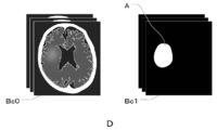
- FIG. 3 is a diagram for explaining the first teacher data D in which the CT image Bc0 and the correct answer mask Bc1 are combined.
- the first teacher data D is a CT image Bc0 which is a learning image for learning the learning model 25 described later, and a correct mask in which the infarct region A is defined as the correct region in the CT image Bc0. It is the teacher data combined with Bc1.
- the CT image Bc0 is a three-dimensional image, but here, for the sake of explanation, a two-dimensional tomographic image on one tomographic plane of the CT image Bc0 will be used.
- the correct answer mask Bc1 is defined by painting the infarct region A, which is the correct answer region, in white, but the correct answer mask Bc1 is not limited to this.
- the infarct region A may be defined by drawing the boundary of the infarct region A in white without filling the inside of the infarct region A. Further, it may be drawn in a color other than white. Further, the infarct region A may be defined by forming an image in which the inside of the infarct region A and the outside of the infarction region A are composed of pixels having different pixel values.
- the CT image Bc0 of the present exemplary embodiment corresponds to the learning image of the present disclosure
- the correct answer mask Bc1 of the present exemplary embodiment corresponds to the correct answer learning image of the present disclosure.
- the teacher data acquisition unit 21 acquires the first teacher data D from the storage 13. May be good.
- the teacher data acquisition unit 21 acquires the first teacher data D for a large number of subjects for learning the learning model 25 described later.
- the teacher data acquisition unit 21 acquires the second teacher data F, which will be described later, from the storage 13.
- the display control unit 26 causes the display unit 14 to display the CT image Bc0, the correct answer mask Bc1, and the variable CT image Bc2 that constitute the first teacher data D and the second teacher data F acquired by the teacher data acquisition unit 21, respectively.
- the constraint range acquisition unit 22 acquires the constraint range of the pixel value that can be taken by the pixel belonging to the infarct region A in the CT image Bc0.
- the CT image Bc0 is a CT image.
- the CT value expresses water as the origin of 0 and the state of air as the lowest value of -1000.
- -1000 of air is set to be represented in black on the CT image Bc0.
- each pixel constituting the image is given a black-and-white shading value (also referred to as a pixel value) to obtain a CT image Bc0. Be expressed.
- the possible pixel value of the infarcted region A in the acute phase on the CT image Bc0 is about 20 to 30. Therefore, in the present exemplary embodiment, the constraint range acquisition unit 22 acquires the lower limit value L of the constraint range of the possible pixel values of the infarct region A as 20 and the upper limit value U as 32.
- the values of the lower limit value L and the upper limit value U are input by the user operating the input unit 15. In the present exemplary embodiment, the values of the lower limit value L and the upper limit value U are input by the user, but the technique of the present disclosure is not limited to this.
- a correspondence table in which the lower limit value L and the upper limit value U are set for each type of image such as a CT image, an MRI image, and a PET image is stored in the storage 13 in advance, and the teacher data acquisition unit 21 acquires the correspondence table.
- the values of the lower limit value L and the upper limit value U may be derived from the above correspondence table.
- the values of the lower limit value L and the upper limit value U can be derived from the type of the learning image, the value is not limited to the correspondence table, and may be derived by, for example, an equation.
- the constraint range acquisition unit 22 sets the lower limit value L of the constraint range of the possible pixel values of the infarct region A to 20 and the upper limit value U to 32. Obtained as.
- the values of the lower limit value L and the upper limit value U that is, the above-mentioned restriction range are appropriately set according to the target to be detected. For example, when the learning image is a CT image and it is desired to detect cerebral hemorrhage in the brain image, the correct answer region is the bleeding region, so the restriction range of the pixel value that the bleeding region can take is about 50 to 80.
- the lower limit value L and the upper limit value U of the pixel values are statistically obtained in advance for each type, model number, manufacturer, imaged facility, and type of lesion to be detected, for example, of the device that captured the learning image. It may be set based on the numerical data obtained by statistics.
- the variation learning image generation unit 23 is an image for variation learning in which the pixel values of the pixels belonging to the infarct region A are varied within the constraint range of the pixel values that the pixels belonging to the infarction region A can take in the CT image Bc0.
- a variable CT image Bc2 is generated.
- FIG. 4 is a diagram for explaining the infarcted region A. In FIG. 4, although the shape of the infarct region A is different from the actual shape, the infarct region A will be described as a square region composed of 16 pixels in 4 rows and 4 columns for the sake of clarity.
- the infarct region A is composed of 16 pixels P11 to P44 arranged in 4 rows and 4 columns. Since each pixel P11 to P44 constituting the infarct region A is a pixel indicating an infarct region, the pixel value is 20 or more and 32 or less.
- FIG. 5 is a graph showing the distribution of pixel values of pixels P11 to P44 belonging to the infarct region A
- FIG. 6 is a graph for explaining fluctuations in pixel values of pixels belonging to the infarct region A.
- the horizontal axis represents the pixel value and the vertical axis represents the frequency of appearance.
- the pixel values of the pixels P11 to P44 constituting the infarct region A are between the lower limit value L (20) and the upper limit value U (32) of the possible pixel value constraint range of the infarct region A. It is distributed in. For example, when the maximum value of the pixel values of the pixels P11 to P44 constituting the infarct region A is 25, it is possible to add up to the value of "7" that reaches 32 of the upper limit value U of the above restriction range. is there. Therefore, a numerical value of 0 or more and 7 or less is randomly selected, and the selected numerical value is added to the pixel values of all the pixels P11 to P44 constituting the infarct region A. As a result, as shown in FIG. 6, the distribution shown by the dotted line of the pixel values of the pixels P11 to P44 belonging to the infarct region A is shifted in the right arrow direction by the added numerical value, and becomes the distribution shown by the solid line.
- the number of numerical values randomly selected from 0 or more and 7 or less and 0 or more and 2 or less is determined based on a preset number of variable CT images Bc2 (described later) to be generated. For example, when it is desired to generate three variable CT images Bc2, three numerical values are randomly selected from a numerical value of 0 or more and 7 or less and a numerical value of 0 or more and 2 or less.
- the number of variable CT images Bc2 to be generated can be arbitrarily set by the user using the input unit 15.
- the variation learning image generation unit 23 generates a variation CT image Bc2 by varying the pixel values of the pixels belonging to the infarct region A based on the selected numerical value, that is, the shift amount.
- FIG. 7 is a diagram for explaining a variation CT image Bc2 generated by adding variation to the CT image Bc0.
- the variable CT image Bc2 exaggerates and changes the pixel value of the infarcted region A in order to clearly show the difference from the CT image Bc0.
- the variation learning image generation unit 23 adds a numerical value selected from a numerical value of 0 or more and 7 or less to the pixel values of all the pixels belonging to the infarct region A in the CT image Bc0, or CT.
- a value selected from a value of 0 or more and 2 or less is subtracted from the pixel values of all the pixels belonging to the infarcted region A in the image Bc0.
- the variation learning image generation unit 23 generates the variation CT image Bc2 in which the pixel value of the infarct region A of the CT image Bc0 is varied.
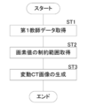
- FIG. 8 is a flowchart showing a process of generating the variable CT image Bc2.
- the teacher data acquisition unit 21 acquires the first teacher data D in which the CT image Bc0 and the correct answer mask Bc1 are paired (step ST1).
- the constraint range acquisition unit 22 acquires the constraint range of the pixel value that can be taken by the pixel belonging to the infarct region A in the CT image Bc0 (step ST2).
- the variation learning image generation unit 23 generates a variation CT image Bc2 by giving variation to the pixel value of the infarct region A of the CT image Bc0 as described above (step ST3), and performs a series of processes. finish.
- the learning image generation device of this exemplary embodiment composed of the teacher data acquisition unit 21, the constraint range acquisition unit 22, and the variation learning image generation unit 23, the learning image generation method of this exemplary embodiment, and the book.
- the learning image generation program of the exemplary embodiment the pixel values of the pixels belonging to the infarct region A are changed within the constraint range of the possible pixel values of the pixels belonging to the infarction region A in the CT image Bc0. It is possible to easily generate a variable CT image Bc2 in which the pixel values of the pixels belonging to the infarct region A are different from those of the CT image Bc0.
- variable value it is possible to generate a plurality of variable CT images Bc2 having different pixel values of the pixels belonging to the infarct region A.
- the limited CT image Bc0 can be used to generate variable CT images Bc2 having different pixel values of the infarct region A, thus covering the diversity of the pixel values of the infarct region A to be segmented. be able to.
- the learning image generation device is configured by the teacher data acquisition unit 21, the constraint range acquisition unit 22, and the variation learning image generation unit 23.
- the technique of the present disclosure is not limited to this, and the constraint range acquisition unit 22 may not be provided.
- the variation learning image generation unit 23 may vary the pixel values of the pixels belonging to the infarct region A based on a predetermined constraint range.
- the variation learning image generation unit 23 varies the pixel values of all the pixels belonging to the infarct region A in the CT image Bc0 by a constant value.
- the pixel values of some of the pixels belonging to the infarct region A may be changed by a constant value.
- FIG. 9 is a diagram for explaining a method of changing the pixel value in the second exemplary embodiment.
- the variation learning image generation unit 23 fluctuates the pixel values of the three pixels shown by the diagonal lines P11, P23, and P41 by a constant value, as an example.
- the number of pixels that fluctuate the pixel value and the number of pixels that fluctuate the pixel value may be set in advance or may be set randomly.
- the variation learning image generation unit 23 varies all the pixel values of the pixels belonging to the infarct region A in the CT image Bc0 by a constant value. I let you.
- the techniques of the present disclosure are not limited to this. For example, it may be changed by a different value for each pixel.
- FIG. 10 is a diagram for explaining a method of changing the pixel value in the third exemplary embodiment.
- the variation learning image generation unit 23 varies the pixel values of the three pixels shown by the diagonal lines P23, P33, and P41 by the first value, as an example. Further, the pixel values of the two pixels of the pixel P11 and the pixel P44 shown by shading are changed by the second value.
- the number of pixels that fluctuate the pixel value with the first value and the number of pixels that fluctuate the pixel value with the first value, and the pixels that fluctuate the pixel value with the second value and the pixel value fluctuate with the second value.
- the number of pixels to be made may be set in advance or may be set randomly.
- the variation learning image generation unit 23 changes the pixel values of the pixels belonging to the infarct region A in the CT image Bc0 to obtain the distribution shown in FIG.
- the graph moves or transforms.
- the techniques of the present disclosure are not limited to this.
- the pixels belonging to the infarct region A may be replaced.
- FIG. 11 is a diagram for explaining a method of changing the pixel value in the fourth exemplary embodiment.
- the variation learning image generation unit 23 replaces the pixel value of the pixel P41 indicated by the diagonal line from the upper right to the lower left with the pixel value of the pixel P44 indicated by shading, as an example. Further, the pixel value of the pixel P33 indicated by the diagonal line from the upper left to the lower right is replaced with the pixel value of the pixel P41 indicated by the diagonal line from the upper right to the lower left. Further, the pixel value of the pixel P44 indicated by shading is replaced with the pixel value of the pixel P33 indicated by a diagonal line extending from the upper left to the lower right.
- the pixel values of the pixels belonging to the infarct region A can be changed while maintaining the graph of the distribution shown in FIG.
- the number of pixels whose pixel values are exchanged and the number of pixels whose pixel values are exchanged may be set in advance or may be set randomly.
- the average and standard deviation of the pixel values of the infarcted region A may be set in advance to determine the normal distribution, and the pixel values may be varied based on the determined normal distribution.
- FIG. 12 is a diagram for explaining a method of changing the pixel value in the fifth exemplary embodiment.
- the variation learning image generation unit 23 sets an average and a standard deviation between the lower limit value L and the upper limit value U of the possible pixel value constraint range of the infarct region A.
- the normal distribution of the pixel values of the infarct region A is determined.
- the variation learning image generation unit 23 fluctuates the pixel value in the infarct region A so that the pixel of each pixel value exists based on the graph of FIG.
- the variation CT image Bc2 generated by the variation learning image generation unit 23 as described above is stored in the storage 13 as image data constituting the second teacher data F.
- FIG. 13 is a diagram for explaining the second teacher data F in which the variable CT image Bc2 and the correct CT image Bc1 are combined.
- the second teacher data F is teacher data in which the variable CT image Bc2 and the correct answer mask Bc1 in which the infarct region A is defined in the CT image Bc0 before the fluctuation of the variable CT image Bc2 are combined. is there.
- the second teacher data F is a combination of the variable CT image Bc2 and the correct mask Bc1 in which the infarct region A is defined in the CT image Bc0 before the fluctuation.
- the correct answer mask Bc3, which newly defines the infarct region A in the variable CT image Bc2, may be paired. However, in the variable CT image Bc2, in the CT image Bc0 before the change, the pixel values of the pixels belonging to the infarct region A are changed within the constraint range of the pixel values that the infarct region A can take.
- the correct answer mask is the same as the correct answer mask Bc3 in which the infarct region A is newly defined in the variable CT image Bc2.
- FIG. 14 is a diagram for explaining a learning method of the learning model.
- the learning model 25 corresponds to the model of the present disclosure.
- the learning model 25 is a model trained to output the infarcted region in the CT image when the CT image to be detected for detecting the infarcted region is input.
- the learning model 25 has a U-Net (U Networks) structure.
- U-Net is one of the full-layer convolutional networks (FCNs) and is a network specialized for image segmentation.
- the learning unit 24 causes the learning model M to learn the infarct region A in the CT image Bc0 by inputting the first teacher data D, that is, the CT image Bc0 and the correct answer mask Bc1 into the learning model M.
- the learning model M is trained so that the region matching the correct mask Bc1 is output as the infarct region A.
- the learning unit 24 causes the learning model M to learn the infarct region A in the variable CT image Bc2 by inputting the second teacher data F, that is, the variable CT image Bc2 and the correct answer mask Bc1 into the learning model M.
- the learning model M is trained so that the region matching the correct mask Bc1 is output as the infarct region A.
- n teacher data are trained by the learning model 25 in order.
- the training model 25 is made to learn the n teacher data again in order for the second time, and the same teacher data is used for a predetermined number of times to repeat the learning model 25. Is being trained.
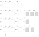
- FIG. 15 is a diagram for explaining a learning method using the first teacher data D and the second teacher data F in the sixth exemplary embodiment.
- the first teacher data D and the second teacher data F are a set of a CT image Bc0 or a variable CT image Bc2 and a correct answer mask Bc1, that is, they are composed of two image data.
- the teacher data D and the second teacher data F are represented by one image for convenience of explanation. It may be expressed in the same manner in the following drawings.
- the learning unit 24 trains the learning model 25 using n first teacher data D1 to Dn at the time of the first learning (1T).
- the learning model 25 is trained by replacing the first teacher data D1 with the second teacher data F1.
- the second teacher data F1 is returned to the first teacher data D1
- the first teacher data D2 is replaced with the second teacher data F2 to train the learning model 25.
- the second teacher data F2 is returned to the first teacher data D2, and the first teacher data D3 is replaced with the second teacher data F3 to train the learning model 25.
- the first teacher data D of one of n first teacher data D1 to Dn is used as the second teacher data for each learning.
- the learning model 25 is trained instead of F.
- FIG. 16 is a flowchart showing the processing performed at the time of learning.
- the teacher data acquisition unit 21 acquires the first teacher data D and the second teacher data F from the image storage server 3 and the storage 13 (step ST11).
- the learning unit 24 trains the learning model 25 as described above using the acquired first teacher data D and the second teacher data F (step ST12), and ends a series of processes.
- the second teacher data F which is a combination of the variable CT image Bc2 and the correct answer mask Bc1, whose pixel values of the pixels belonging to the infarct region A are different from the image Bc0, is used for learning.
- the variable CT image Bc2 in which the infarct region A of the value is defined is used as the teacher data. Therefore, in this exemplary embodiment, it is possible to cover the variety of pixel values of the infarct region A that is the target of segmentation.
- the learning model 25 was trained by replacing one first teacher data D with the second teacher data F each time.
- the two first teacher data D may be replaced with the second teacher data F, or any number of first teacher data D such as three or four may be replaced with the second teacher data F.
- only the predetermined first teacher data D may be replaced with the second teacher data F which is different each time.
- the first teacher data D to be changed to the second teacher data F may be randomly selected.
- the number of the first teacher data D to be changed to the second teacher data F may be randomly determined.
- FIG. 17 is a diagram for explaining a learning method using the first teacher data D and the second teacher data F in the seventh exemplary embodiment.
- the learning unit 24 trains the learning model 25 using n first teacher data D1 to Dn at the time of the first learning (1T).
- the learning model 25 is trained by replacing the first teacher data D1 with the second teacher data F1.
- the second teacher data F1 is returned to the first teacher data D1
- the first teacher data D2 is returned to the second teacher data F2
- the first teacher data D4 is changed to the second teacher.
- the data F4 is replaced with the first teacher data D5 by the second teacher data F5, and the learning model 25 is trained.
- the second teacher data F2 becomes the first teacher data D2
- the second teacher data F4 becomes the first teacher data D4
- the second teacher data F5 becomes the first teacher data D5.
- the learning model 25 is trained by replacing the first teacher data D1 with the second teacher data F1 and the first teacher data D3 with the second teacher data F3.
- the learning model 25 is trained by replacing the first teacher data D with the second teacher data F in each of the second and subsequent learning sessions.
- the learning model 25 may be trained by adding the second teacher data F to the n first teacher data Dn each time.
- FIG. 18 is a diagram for explaining a learning method using the first teacher data D and the second teacher data F in the eighth exemplary embodiment.
- the learning unit 24 trains the learning model 25 using n first teacher data D1 to Dn at the time of the first learning (1T).
- the second teacher data F1 is added to train the learning model 25.
- the second teacher data F2 is added to train the learning model 25.
- the second teacher data F3 is added to train the learning model 25.
- a learning model is added by adding one second teacher data F to the n first teacher data D1 to Dn each time. Learn 25. When n + 1 learning is completed, the process returns to the first learning (1T), and the above learning is repeated until the set number of learning is completed.
- the learning model 25 was trained by adding one second teacher data F each time in the second and subsequent learnings.
- Two second teacher data Fs may be added, or any number of second teacher data Fs, such as three or four, may be added. Further, the second teacher data F to be added may be randomly selected.
- FIG. 19 is a diagram for explaining a learning method using the first teacher data D and the second teacher data F in the ninth exemplary embodiment.
- the learning unit 24 trains the learning model 25 using n first teacher data D1 to Dn at the time of the first learning (1T).
- the learning model 25 is trained by adding the second teacher data F2, the second teacher data F3, and the second teacher data F5.
- the second teacher data F4 is added to train the learning model 25.
- the second teacher data F1 and the second teacher data F4 are added to train the learning model 25.
- a random number of second teacher data Fs are added to n first teacher data D1 to Dn each time.
- the learning model 25 is trained until the set number of learnings is completed.
- FIG. 20 is a diagram for explaining a learning method using the first teacher data D and the second teacher data F in the tenth exemplary embodiment.
- the learning unit 24 uses only n first teacher data D1 to Dn at least once in the second and subsequent learnings, and in the seventh learning in this exemplary embodiment.
- the learning model 25 is trained.
- the number of times the learning model 25 is trained using only n first teacher data D1 to Dn is not limited to the seventh time, and may be any time. Further, the learning model 25 may be trained using only the first teacher data D1 to Dn twice, three times, and n times.
- the disease is infarction, but the technique of the present disclosure is not limited to this, and the disease may be bleeding or the like, for example.
- a CT image is used as the learning image of the present disclosure.
- the technique of the present disclosure is not limited to this, and the learning image of the present disclosure may be another medical image such as a PET image, an ultrasonic image, and an MRI image.
- the MRI image may be any of a T1 image, a T2 image, and a diffusion-weighted image.
- a brain image is used as a medical image, but the present invention is not limited to this.
- the present disclosure can also be applied to discriminate disease areas and areas of interest included in medical images of the chest, abdomen, whole body, limbs, etc. of the human body.
- the learning device 1 includes a learning image generating device, but the technique of the present disclosure is not limited to this, and the learning image generating device may not be included. ..
- the learning device 1 shall include the teacher data acquisition unit 21, so that the teacher data acquisition unit 21 acquires the second teacher data including the variable learning image generated by the external learning generation device. It should be.
- the learning model 25 has a U-Net structure, but the technique of the present disclosure is not limited to this.
- a full-layer convolutional network (FCN) other than U-Net may be used.
- FCN full-layer convolutional network
- various processes such as the teacher data acquisition unit 21, the constraint range acquisition unit 22, the variation learning image generation unit 23, the learning unit 24, the learning model 25, and the display control unit 26 are performed.
- various processors processors shown below can be used.
- the various processors include a CPU, which is a general-purpose processor that executes software (program) and functions as various processing units, and a circuit after manufacturing an FPGA (Field Programmable Gate Array) or the like.
- Dedicated electricity which is a processor with a circuit configuration specially designed to execute specific processing such as programmable logic device (PLD), ASIC (Application Specific Integrated Circuit), which is a processor whose configuration can be changed. Circuits and the like are included.
- One processing unit may be composed of one of these various processors, or a combination of two or more processors of the same type or different types (for example, a combination of a plurality of FPGAs or a combination of a CPU and an FPGA). ) May be configured. Further, a plurality of processing units may be configured by one processor.
- one processor is configured by combining one or more CPUs and software. There is a form in which this processor functions as a plurality of processing units.
- SoC System On Chip
- the various processing units are configured by using one or more of the various processors as a hardware structure.
- circuitry in which circuit elements such as semiconductor elements are combined can be used.
Landscapes
- Engineering & Computer Science (AREA)
- Theoretical Computer Science (AREA)
- General Physics & Mathematics (AREA)
- Computer Vision & Pattern Recognition (AREA)
- Physics & Mathematics (AREA)
- General Health & Medical Sciences (AREA)
- Medical Informatics (AREA)
- Health & Medical Sciences (AREA)
- Databases & Information Systems (AREA)
- Computing Systems (AREA)
- Artificial Intelligence (AREA)
- Evolutionary Computation (AREA)
- Software Systems (AREA)
- Multimedia (AREA)
- Quality & Reliability (AREA)
- Radiology & Medical Imaging (AREA)
- Nuclear Medicine, Radiotherapy & Molecular Imaging (AREA)
- Image Analysis (AREA)
- Apparatus For Radiation Diagnosis (AREA)
Priority Applications (2)
| Application Number | Priority Date | Filing Date | Title |
|---|---|---|---|
| JP2021527754A JP7307166B2 (ja) | 2019-06-28 | 2020-06-26 | 学習用画像生成装置、方法及びプログラム、並びに学習方法、装置及びプログラム |
| US17/562,988 US12217488B2 (en) | 2019-06-28 | 2021-12-27 | Learning image generation device, learning image generation method, learning image generation program, learning method, learning device, and learning program |
Applications Claiming Priority (2)
| Application Number | Priority Date | Filing Date | Title |
|---|---|---|---|
| JP2019-121325 | 2019-06-28 | ||
| JP2019121325 | 2019-06-28 |
Related Child Applications (1)
| Application Number | Title | Priority Date | Filing Date |
|---|---|---|---|
| US17/562,988 Continuation US12217488B2 (en) | 2019-06-28 | 2021-12-27 | Learning image generation device, learning image generation method, learning image generation program, learning method, learning device, and learning program |
Publications (1)
| Publication Number | Publication Date |
|---|---|
| WO2020262571A1 true WO2020262571A1 (ja) | 2020-12-30 |
Family
ID=74061763
Family Applications (1)
| Application Number | Title | Priority Date | Filing Date |
|---|---|---|---|
| PCT/JP2020/025121 Ceased WO2020262571A1 (ja) | 2019-06-28 | 2020-06-26 | 学習用画像生成装置、方法及びプログラム、並びに学習方法、装置及びプログラム |
Country Status (3)
| Country | Link |
|---|---|
| US (1) | US12217488B2 (https=) |
| JP (1) | JP7307166B2 (https=) |
| WO (1) | WO2020262571A1 (https=) |
Citations (2)
| Publication number | Priority date | Publication date | Assignee | Title |
|---|---|---|---|---|
| JPH11282822A (ja) * | 1998-03-26 | 1999-10-15 | Toshiba Corp | 画像処理プログラム合成方法及びその装置並びに最適解探索方法及びその装置 |
| JP2006337152A (ja) * | 2005-06-01 | 2006-12-14 | Sharp Corp | 教示用画像生成方法および装置、画像処理アルゴリズム生成方法および装置、画像検査方法および装置、プログラムならびに記録媒体 |
Family Cites Families (10)
| Publication number | Priority date | Publication date | Assignee | Title |
|---|---|---|---|---|
| WO2006114003A1 (en) * | 2005-04-27 | 2006-11-02 | The Governors Of The University Of Alberta | A method and system for automatic detection and segmentation of tumors and associated edema (swelling) in magnetic resonance (mri) images |
| JP2018005640A (ja) | 2016-07-04 | 2018-01-11 | タカノ株式会社 | 分類器生成装置、画像検査装置、及び、プログラム |
| US11793478B2 (en) * | 2017-03-28 | 2023-10-24 | Canon Medical Systems Corporation | Medical image processing apparatus, medical image processing method, and X-ray diagnostic apparatus |
| US10262236B2 (en) * | 2017-05-02 | 2019-04-16 | General Electric Company | Neural network training image generation system |
| US10152571B1 (en) * | 2017-05-25 | 2018-12-11 | Enlitic, Inc. | Chest x-ray differential diagnosis system |
| US11419584B2 (en) * | 2017-06-28 | 2022-08-23 | Tokitae, LLC | Devices, systems, and methods for diagnosis of pulmonary conditions through detection of b-lines in lung sonography |
| JP7097686B2 (ja) * | 2017-11-15 | 2022-07-08 | 大日本印刷株式会社 | 画像解析装置 |
| JP7091635B2 (ja) * | 2017-11-15 | 2022-06-28 | 大日本印刷株式会社 | 対象物検出器、画像解析装置、対象物検出方法、画像解析方法、プログラム、及び、学習データ |
| JP7218118B2 (ja) * | 2018-07-31 | 2023-02-06 | キヤノン株式会社 | 情報処理装置、情報処理方法およびプログラム |
| JP7258568B2 (ja) * | 2019-01-18 | 2023-04-17 | キヤノンメディカルシステムズ株式会社 | 超音波診断装置、画像処理装置、及び画像処理プログラム |
-
2020
- 2020-06-26 JP JP2021527754A patent/JP7307166B2/ja active Active
- 2020-06-26 WO PCT/JP2020/025121 patent/WO2020262571A1/ja not_active Ceased
-
2021
- 2021-12-27 US US17/562,988 patent/US12217488B2/en active Active
Patent Citations (2)
| Publication number | Priority date | Publication date | Assignee | Title |
|---|---|---|---|---|
| JPH11282822A (ja) * | 1998-03-26 | 1999-10-15 | Toshiba Corp | 画像処理プログラム合成方法及びその装置並びに最適解探索方法及びその装置 |
| JP2006337152A (ja) * | 2005-06-01 | 2006-12-14 | Sharp Corp | 教示用画像生成方法および装置、画像処理アルゴリズム生成方法および装置、画像検査方法および装置、プログラムならびに記録媒体 |
Also Published As
| Publication number | Publication date |
|---|---|
| JPWO2020262571A1 (https=) | 2020-12-30 |
| US12217488B2 (en) | 2025-02-04 |
| US20220122350A1 (en) | 2022-04-21 |
| JP7307166B2 (ja) | 2023-07-11 |
Similar Documents
| Publication | Publication Date | Title |
|---|---|---|
| JP7246866B2 (ja) | 医用画像処理装置 | |
| US20200058098A1 (en) | Image processing apparatus, image processing method, and image processing program | |
| US11238197B1 (en) | Generating a 3D dataset containing a simulated surgical device | |
| US10956635B1 (en) | Radiologist-assisted machine learning with interactive, volume subtending 3D cursor | |
| JP2018505705A (ja) | 機械学習を用いた医用イメージングの変換のためのシステムおよび方法 | |
| CN113424222A (zh) | 用于使用条件生成对抗网络提供中风病灶分割的系统和方法 | |
| JP7170897B2 (ja) | 学習装置、方法およびプログラム、画像生成装置、方法およびプログラム、並びに画像生成モデル | |
| JP7129870B2 (ja) | 疾患領域を判別する判別器の学習装置、方法及びプログラム、疾患領域を判別する判別器、並びに疾患領域判別装置及びプログラム | |
| KR102067412B1 (ko) | 치매 평가 방법 및 이를 이용한 장치 | |
| JP2021140769A (ja) | 医用情報処理装置、医用情報処理方法及び医用情報処理プログラム | |
| US12579720B2 (en) | Method of generating trained model, machine learning system, program, and medical image processing apparatus | |
| JP2021099794A (ja) | ディープニューラルネットワークおよび測定データの再帰的間引きを使用して医用画像を再構築するためのシステムおよび方法 | |
| JP6981940B2 (ja) | 画像診断支援装置、方法及びプログラム | |
| US12217852B2 (en) | Image processing device, image processing method, image processing program, learning device, learning method, learning program, and derivation model | |
| US11176413B2 (en) | Apparatus, method, and program for training discriminator discriminating disease region, discriminator discriminating disease region, disease region discrimination apparatus, and disease region discrimination program | |
| CN120510080A (zh) | 用于提供医学图像的图像获取信息的方法和系统 | |
| KR20190114229A (ko) | 영상 처리 장치 및 방법 | |
| US12205710B2 (en) | Image generation device, image generation method, image generation program, learning device, learning method, and learning program | |
| CN119894427A (zh) | 模拟图像中的结构 | |
| JP7321271B2 (ja) | 学習用画像生成装置、方法及びプログラム、並びに学習方法、装置及びプログラム | |
| JP7307166B2 (ja) | 学習用画像生成装置、方法及びプログラム、並びに学習方法、装置及びプログラム | |
| CN115398482A (zh) | 创建合成医学图像 | |
| WO2020262681A1 (ja) | 学習装置、方法およびプログラム、医用画像処理装置、方法およびプログラム、並びに判別器 | |
| US20230293014A1 (en) | Plane selection using localizer images | |
| JP2023114463A (ja) | 表示装置、方法およびプログラム |
Legal Events
| Date | Code | Title | Description |
|---|---|---|---|
| 121 | Ep: the epo has been informed by wipo that ep was designated in this application |
Ref document number: 20832981 Country of ref document: EP Kind code of ref document: A1 |
|
| ENP | Entry into the national phase |
Ref document number: 2021527754 Country of ref document: JP Kind code of ref document: A |
|
| NENP | Non-entry into the national phase |
Ref country code: DE |
|
| 122 | Ep: pct application non-entry in european phase |
Ref document number: 20832981 Country of ref document: EP Kind code of ref document: A1 |