WO2020262571A1 - Learning image generation device, method and program , and learning method, device and program - Google Patents
Learning image generation device, method and program , and learning method, device and program Download PDFInfo
- Publication number
- WO2020262571A1 WO2020262571A1 PCT/JP2020/025121 JP2020025121W WO2020262571A1 WO 2020262571 A1 WO2020262571 A1 WO 2020262571A1 JP 2020025121 W JP2020025121 W JP 2020025121W WO 2020262571 A1 WO2020262571 A1 WO 2020262571A1
- Authority
- WO
- WIPO (PCT)
- Prior art keywords
- learning
- teacher data
- image
- correct answer
- learning image
- Prior art date
Links
Images


Classifications
-
- G—PHYSICS
- G06—COMPUTING; CALCULATING OR COUNTING
- G06T—IMAGE DATA PROCESSING OR GENERATION, IN GENERAL
- G06T7/00—Image analysis
- G06T7/0002—Inspection of images, e.g. flaw detection
- G06T7/0012—Biomedical image inspection
-
- G—PHYSICS
- G06—COMPUTING; CALCULATING OR COUNTING
- G06T—IMAGE DATA PROCESSING OR GENERATION, IN GENERAL
- G06T7/00—Image analysis
- G06T7/10—Segmentation; Edge detection
- G06T7/11—Region-based segmentation
-
- G—PHYSICS
- G06—COMPUTING; CALCULATING OR COUNTING
- G06V—IMAGE OR VIDEO RECOGNITION OR UNDERSTANDING
- G06V10/00—Arrangements for image or video recognition or understanding
- G06V10/70—Arrangements for image or video recognition or understanding using pattern recognition or machine learning
- G06V10/77—Processing image or video features in feature spaces; using data integration or data reduction, e.g. principal component analysis [PCA] or independent component analysis [ICA] or self-organising maps [SOM]; Blind source separation
- G06V10/774—Generating sets of training patterns; Bootstrap methods, e.g. bagging or boosting
- G06V10/7747—Organisation of the process, e.g. bagging or boosting
-
- G—PHYSICS
- G06—COMPUTING; CALCULATING OR COUNTING
- G06V—IMAGE OR VIDEO RECOGNITION OR UNDERSTANDING
- G06V10/00—Arrangements for image or video recognition or understanding
- G06V10/70—Arrangements for image or video recognition or understanding using pattern recognition or machine learning
- G06V10/77—Processing image or video features in feature spaces; using data integration or data reduction, e.g. principal component analysis [PCA] or independent component analysis [ICA] or self-organising maps [SOM]; Blind source separation
- G06V10/778—Active pattern-learning, e.g. online learning of image or video features
- G06V10/7784—Active pattern-learning, e.g. online learning of image or video features based on feedback from supervisors
- G06V10/7792—Active pattern-learning, e.g. online learning of image or video features based on feedback from supervisors the supervisor being an automated module, e.g. "intelligent oracle"
-
- G—PHYSICS
- G06—COMPUTING; CALCULATING OR COUNTING
- G06T—IMAGE DATA PROCESSING OR GENERATION, IN GENERAL
- G06T2207/00—Indexing scheme for image analysis or image enhancement
- G06T2207/10—Image acquisition modality
- G06T2207/10072—Tomographic images
- G06T2207/10081—Computed x-ray tomography [CT]
-
- G—PHYSICS
- G06—COMPUTING; CALCULATING OR COUNTING
- G06T—IMAGE DATA PROCESSING OR GENERATION, IN GENERAL
- G06T2207/00—Indexing scheme for image analysis or image enhancement
- G06T2207/10—Image acquisition modality
- G06T2207/10072—Tomographic images
- G06T2207/10088—Magnetic resonance imaging [MRI]
-
- G—PHYSICS
- G06—COMPUTING; CALCULATING OR COUNTING
- G06T—IMAGE DATA PROCESSING OR GENERATION, IN GENERAL
- G06T2207/00—Indexing scheme for image analysis or image enhancement
- G06T2207/10—Image acquisition modality
- G06T2207/10072—Tomographic images
- G06T2207/10104—Positron emission tomography [PET]
-
- G—PHYSICS
- G06—COMPUTING; CALCULATING OR COUNTING
- G06T—IMAGE DATA PROCESSING OR GENERATION, IN GENERAL
- G06T2207/00—Indexing scheme for image analysis or image enhancement
- G06T2207/20—Special algorithmic details
- G06T2207/20081—Training; Learning
-
- G—PHYSICS
- G06—COMPUTING; CALCULATING OR COUNTING
- G06T—IMAGE DATA PROCESSING OR GENERATION, IN GENERAL
- G06T2207/00—Indexing scheme for image analysis or image enhancement
- G06T2207/20—Special algorithmic details
- G06T2207/20084—Artificial neural networks [ANN]
-
- G—PHYSICS
- G06—COMPUTING; CALCULATING OR COUNTING
- G06T—IMAGE DATA PROCESSING OR GENERATION, IN GENERAL
- G06T2207/00—Indexing scheme for image analysis or image enhancement
- G06T2207/30—Subject of image; Context of image processing
- G06T2207/30004—Biomedical image processing
- G06T2207/30016—Brain
-
- G—PHYSICS
- G06—COMPUTING; CALCULATING OR COUNTING
- G06V—IMAGE OR VIDEO RECOGNITION OR UNDERSTANDING
- G06V2201/00—Indexing scheme relating to image or video recognition or understanding
- G06V2201/03—Recognition of patterns in medical or anatomical images
Definitions
- the present disclosure relates to a learning image generator, a method and a program, and a learning method, a device and a program.
- a convolutional neural network (CNN) is generated by deep learning based on the first teacher data including a plurality of first images showing defects, and is used as an intermediate layer of the CNN.
- CNN convolutional neural network
- Each of the plurality of second images showing defects is input, a plurality of types of feature quantities for each of the plurality of second images are acquired from this intermediate layer, and further machine learning is performed using the plurality of types of feature quantities.
- a method for constructing a model with improved classification accuracy is disclosed.
- the model is trained by end-to-end (end-to-end) deep learning using the teacher data in which the learning image and the correct learning image in which the correct answer region is defined in the learning image are paired.
- End-to-end deep learning is a method of learning all intermediate processes that occur in the process from the time an input is given until the result is output.
- the learning model learned by end-to-end deep learning by inputting an image into the learning model, it is possible to perform semantic segmentation that classifies by labeling the entire input image in pixel units. ..
- the more learning images and correct answer learning images are on the input side and the output side the more accurate the output result can be obtained. ..
- the image to be input is, for example, a brain image of a brain that has developed a disease such as stroke
- the disease areas such as the infarcted area and the bleeding area to be segmented have a shape, a size, and an onset site. Etc. are indefinite.
- the pixel value of the diseased area in the brain image changes depending on the elapsed time from the onset of the disease. Therefore, there are various cases in the brain image, and it is difficult to prepare a learning image that can cover all the various cases.
- the present disclosure provides a learning image generator, a method and a program, and a learning method, a device and a program capable of covering a variety of pixel values of an image region to be segmented by using a limited learning image. To do.
- the first aspect of the present disclosure is a learning image generator, which acquires teacher data in which a learning image and a correct learning image in which a correct area is defined in the learning image are combined.
- the variation learning image generation unit that generates a variation learning image in which the pixel values of the pixels belonging to the correct answer region are varied within the constraint range of the pixel values that the pixels belonging to the correct answer region can take. ,including.
- the second aspect of the present disclosure may include a constraint range acquisition unit for acquiring a constraint range in the first aspect.
- the variation learning image generation unit changes the pixel value of one or more pixels among the pixels belonging to the correct answer region by a constant value. May be good.
- the variation learning image generation unit varies the pixel values of one or more pixels among the pixels belonging to the correct answer region by different values for each pixel. You may let me.
- the variation learning image generation unit belongs to the correct answer region according to the normal distribution set based on the pixel values of the pixels belonging to the correct answer region.
- the pixel value of one or more of the pixels may be changed by a different value for each pixel.
- a sixth aspect of the present disclosure is a learning image generation method, in which teacher data in which a learning image and a correct answer learning image in which a correct answer region is defined in the learning image is acquired is acquired and used for learning.
- a variation learning image in which the pixel values of the pixels belonging to the correct answer region are varied within the constraint range of the pixel values that the pixels belonging to the correct answer region can take is generated.
- a seventh aspect of the present disclosure is a learning image generation program, which acquires teacher data in which a learning image and a correct learning image in which a correct area is defined in the learning image are combined.
- a variable learning image generator that generates a variable learning image in which the pixel values of the pixels belonging to the correct answer region are varied within the constraint range of the pixel values that the pixels belonging to the correct answer region can take in the learning image. , Make the computer work.
- a learning image generator comprising a memory for storing instructions to be executed by a computer and a processor configured to execute the stored instructions.
- the teacher data which is a combination of the image for learning and the image for learning correct answer in which the correct answer region is defined in the learning image, is acquired, and in the learning image, within the constraint range of the pixel value that the pixel belonging to the correct answer region can take.
- a process of generating a variation learning image in which the pixel values of the pixels belonging to the correct answer region are varied is executed.
- the eighth aspect of the present disclosure is a learning method, in which one or more first teacher data in which a learning image and a correct answer learning image in which a correct answer region is defined in the learning image are combined, and learning.
- One or more variation learning images and one or more variation learning images generated by varying the pixel values of the pixels belonging to the correct answer region within the constraint range of the pixel values that the pixels belonging to the correct answer region can take.
- the model is trained using one or more second teacher data in combination with the correct answer learning image in which the correct answer region is defined in the learning image before the change.
- the pixel value of one or more pixels of the pixels belonging to the correct answer region may be changed by a constant value, or the pixel value of one or more pixels of the pixels belonging to the correct answer region may be changed. May be changed by a different value for each pixel, or the pixel value of one or more pixels of the pixels belonging to the correct answer region according to the normal distribution set based on the pixel values of the pixels belonging to the correct answer region. May be changed by a different value for each pixel.
- the model is trained using the plurality of first teacher data in the first learning, and among the plurality of first teacher data in the second and subsequent learnings.
- the model may be trained by replacing at least one first teacher data of the above with the second teacher data.
- the model is trained using the plurality of first teacher data in the first learning, and at least one second teacher data is used in the second and subsequent learnings. You may additionally train the model.
- At least one of the second teacher data and the second teacher data to be used is randomly selected for each learning in the second and subsequent learnings. It may be set.
- At least one of the number of the second teacher data and the number of the second teacher data to be used in the second and subsequent learnings may be preset in the ninth or tenth aspect.
- the model may be trained using only the plurality of first teacher data at least once in the second and subsequent learnings.
- a fourteenth aspect of the present disclosure is a learning device, in which one or more first teacher data in which a learning image and a correct answer learning image in which a correct answer region is defined in the learning image are paired, and learning.
- One or more variation learning images and one or more variation learning images generated by varying the pixel values of the pixels belonging to the correct answer region within the constraint range of the pixel values that the pixels belonging to the correct answer region can take.
- Acquired by the teacher data acquisition unit and the teacher data acquisition unit that acquire one or more second teacher data that is a set of the correct answer learning image in which the correct answer region is defined in the learning image before the change in each of the above. It includes a learning unit that trains a model using one or more first teacher data and one or more second teacher data.
- a learning device comprising a memory for storing instructions to be executed by a computer and a processor configured to execute the stored instructions, wherein the processor is a learning image.
- One or more first teacher data in combination with the correct answer learning image in which the correct answer region is defined in the learning image, and within the constraint range of the possible pixel values of the pixels belonging to the correct answer region in the learning image.
- One or more variation learning images generated by varying the pixel values of the pixels belonging to the correct answer region, and one or more variation learning images for correct answer learning in which the correct answer region is defined in the learning image before variation.
- a process of training a model is executed using one or more second teacher data paired with an image.
- the learning unit can train the model by the above learning method.
- the sixteenth aspect of the present disclosure is a learning program, in which one or more first teacher data in which a learning image and a correct answer learning image in which a correct answer region is defined in the learning image are combined, and learning.
- One or more variation learning images and one or more variation learning images generated by varying the pixel values of the pixels belonging to the correct answer region within the constraint range of the pixel values that the pixels belonging to the correct answer region can take.
- the teacher data acquisition unit that acquires one or more second teacher data that is a set of the correct answer learning image in which the correct answer region is defined in the learning image before the change, and the teacher data acquisition unit.
- the computer functions as a learning unit that trains a model using one or more first teacher data and one or more second teacher data.
- the learning image generators, methods and programs of the present disclosure use a limited number of learning images to vary the pixel values of the image region to be segmented. Can cover sex.
- Diagram to illustrate the infarcted area Graph showing the distribution of pixel values of pixels belonging to the infarct region Graph for explaining the fluctuation of the pixel value of the pixel belonging to the infarct region The figure for demonstrating the variation CT image generated by adding variation to a CT image.
- a flowchart showing a process of generating a fluctuating CT image The figure for demonstrating the variation method of the pixel value in the 2nd exemplary Embodiment The figure for demonstrating the variation method of the pixel value in the 3rd exemplary embodiment. The figure for demonstrating the variation method of the pixel value in 4th Example Embodiment. The figure for demonstrating the variation method of the pixel value in 5th Example Embodiment. The figure for demonstrating the 2nd teacher data which combined the variation CT image and the correct answer CT image. Diagram to explain the learning model The figure for demonstrating the learning method using the 1st teacher data and the 2nd teacher data in the 6th exemplary embodiment.
- FIG. 7 The figure for demonstrating the learning method using the 1st teacher data and the 2nd teacher data in a 7th exemplary embodiment.
- FIG. 1 is a hardware configuration diagram showing an outline of a diagnosis support system to which a learning image generation device and a learning device according to the first exemplary embodiment of the present disclosure are applied.
- the learning device 1 in the diagnosis support system, the learning device 1, the three-dimensional image capturing device 2, and the image storage server 3 according to this exemplary embodiment are connected via the network 4 in a communicable state.
- the learning device 1 includes a learning model and a learning image generation device according to this exemplary embodiment.
- the three-dimensional image capturing device 2 is a device that generates a three-dimensional image representing the site by photographing the site to be diagnosed of the subject.
- the three-dimensional imaging apparatus 2 is a CT (Computed Tomography) apparatus, an MRI (Magnetic Resonance Imaging) apparatus, a PET (Positron Emission Tomography) apparatus, and the like.
- the medical image generated by the three-dimensional image capturing device 2 is transmitted to the image storage server 3 and stored.
- the diagnosis target site of the patient who is the subject is the brain
- the three-dimensional imaging device 2 is a CT device. Then, in the CT apparatus, a three-dimensional CT image Bc0 including the brain of the subject is generated.
- the image storage server 3 is a computer that stores and manages various data, and is equipped with a large-capacity external storage device and database management software.
- the image storage server 3 communicates with another device via a wired or wireless network 4 to send and receive image data and the like.
- the image storage server 3 acquires various data including image data of CT images generated by the three-dimensional image capturing device 2 via a network, and stores the data in a recording medium such as a large-capacity external storage device. to manage.
- the storage format of the image data and the communication between the devices via the network 4 are based on a protocol such as DICOM (Digital Imaging and Communication in Medicine).
- DICOM Digital Imaging and Communication in Medicine
- the image storage server 3 also stores and manages the first teacher data D (described later) including the CT image Bc0 which is a learning image for learning the learning model 25 described later. doing.
- the learning device 1 including the learning image generation device and the learning model of the present exemplary embodiment is a computer in which the learning image generation program and the learning program of the present disclosure are installed.
- the computer may be a workstation or personal computer directly operated by the diagnosing doctor, or a server computer connected to them via a network.
- the learning image generation program and the learning program are recorded and distributed on a recording medium such as a DVD (Digital Versatile Disc) or a CD-ROM (Compact Disc Read Only Memory), and are installed on a computer from the recording medium.
- a recording medium such as a DVD (Digital Versatile Disc) or a CD-ROM (Compact Disc Read Only Memory)
- it is stored in a storage device of a server computer connected to a network or in a network storage in a state of being accessible from the outside, and is downloaded and installed in a computer used by a doctor upon request.
- FIG. 2 is a diagram showing a schematic configuration of a learning device 1 which is an exemplary embodiment of the present disclosure realized by installing a learning image generation program and a learning program on a computer.
- the learning device 1 includes a CPU (Central Processing Unit) 11, a memory 12, and a storage 13 as a standard workstation configuration. Further, the learning device 1 is connected to a display unit 14 including a liquid crystal display and the like, and an input unit 15 including a keyboard and a mouse.
- the input unit 15 receives various setting inputs by the user. By using the touch panel, the display unit 14 and the input unit 15 may be used in combination.
- the storage 13 includes a hard disk drive, an SSD (Solid State Drive), and the like.
- the storage 13 contains the first teacher data D including the CT image Bc0, which is a learning image for learning the learning model 25 described later, acquired from the image storage server 3 via the network 4, and is necessary for processing. Various information including information is stored.
- the learning image generation program and the learning program are stored in the memory 12.
- the learning image generation program defines a teacher data acquisition process, a constraint range acquisition process, and a variable learning image generation process as processes to be executed by the CPU 11.
- the teacher data acquisition process the first teacher data D, which is a combination of the learning image and the correct answer learning image in which the correct answer region is defined in the learning image, is acquired.
- the constraint range acquisition process the constraint range of the pixel values that can be taken by the pixels belonging to the correct answer region is acquired in the learning image.
- the variation learning image generation process a variation learning image in which the pixel values of the pixels belonging to the correct answer region are varied within the constraint range is generated.
- the learning program defines teacher data acquisition processing, learning processing, discrimination processing, and display control processing as processing to be executed by the CPU 11.
- the teacher data acquisition process one or more first teacher data in which a learning image and a correct learning image in which a correct area is defined in the learning image are paired, and pixels belonging to the correct area in the learning image.
- One or more fluctuation learning images generated by fluctuating the pixel values of the pixels belonging to the correct answer region within the constraint range of the pixel values that can be taken, and one or more fluctuation learning images, each of which is a learning image before fluctuation.
- the model is trained using the acquired one or more first teacher data and one or more second teacher data.
- the discrimination process when a learning image or a target image to be discriminated is input, the correct answer area in the input image is output.
- the display control process the learning image, the correct answer learning image, the correct answer area, and the like are displayed on the display unit 14.
- the computer has the teacher data acquisition unit 21, the constraint range acquisition unit 22, the variation learning image generation unit 23, the learning unit 24, the learning model 25, and the display control unit. Functions as 26.
- the teacher data acquisition unit 21, the constraint range acquisition unit 22, and the variation learning image generation unit 23 constitute the learning image generation device of this exemplary embodiment.
- the teacher data acquisition unit 21 acquires the first teacher data D from the image storage server 3 via an interface (not shown) connected to the network.
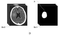
- FIG. 3 is a diagram for explaining the first teacher data D in which the CT image Bc0 and the correct answer mask Bc1 are combined.
- the first teacher data D is a CT image Bc0 which is a learning image for learning the learning model 25 described later, and a correct mask in which the infarct region A is defined as the correct region in the CT image Bc0. It is the teacher data combined with Bc1.
- the CT image Bc0 is a three-dimensional image, but here, for the sake of explanation, a two-dimensional tomographic image on one tomographic plane of the CT image Bc0 will be used.
- the correct answer mask Bc1 is defined by painting the infarct region A, which is the correct answer region, in white, but the correct answer mask Bc1 is not limited to this.
- the infarct region A may be defined by drawing the boundary of the infarct region A in white without filling the inside of the infarct region A. Further, it may be drawn in a color other than white. Further, the infarct region A may be defined by forming an image in which the inside of the infarct region A and the outside of the infarction region A are composed of pixels having different pixel values.
- the CT image Bc0 of the present exemplary embodiment corresponds to the learning image of the present disclosure
- the correct answer mask Bc1 of the present exemplary embodiment corresponds to the correct answer learning image of the present disclosure.
- the teacher data acquisition unit 21 acquires the first teacher data D from the storage 13. May be good.
- the teacher data acquisition unit 21 acquires the first teacher data D for a large number of subjects for learning the learning model 25 described later.
- the teacher data acquisition unit 21 acquires the second teacher data F, which will be described later, from the storage 13.
- the display control unit 26 causes the display unit 14 to display the CT image Bc0, the correct answer mask Bc1, and the variable CT image Bc2 that constitute the first teacher data D and the second teacher data F acquired by the teacher data acquisition unit 21, respectively.
- the constraint range acquisition unit 22 acquires the constraint range of the pixel value that can be taken by the pixel belonging to the infarct region A in the CT image Bc0.
- the CT image Bc0 is a CT image.
- the CT value expresses water as the origin of 0 and the state of air as the lowest value of -1000.
- -1000 of air is set to be represented in black on the CT image Bc0.
- each pixel constituting the image is given a black-and-white shading value (also referred to as a pixel value) to obtain a CT image Bc0. Be expressed.
- the possible pixel value of the infarcted region A in the acute phase on the CT image Bc0 is about 20 to 30. Therefore, in the present exemplary embodiment, the constraint range acquisition unit 22 acquires the lower limit value L of the constraint range of the possible pixel values of the infarct region A as 20 and the upper limit value U as 32.
- the values of the lower limit value L and the upper limit value U are input by the user operating the input unit 15. In the present exemplary embodiment, the values of the lower limit value L and the upper limit value U are input by the user, but the technique of the present disclosure is not limited to this.
- a correspondence table in which the lower limit value L and the upper limit value U are set for each type of image such as a CT image, an MRI image, and a PET image is stored in the storage 13 in advance, and the teacher data acquisition unit 21 acquires the correspondence table.
- the values of the lower limit value L and the upper limit value U may be derived from the above correspondence table.
- the values of the lower limit value L and the upper limit value U can be derived from the type of the learning image, the value is not limited to the correspondence table, and may be derived by, for example, an equation.
- the constraint range acquisition unit 22 sets the lower limit value L of the constraint range of the possible pixel values of the infarct region A to 20 and the upper limit value U to 32. Obtained as.
- the values of the lower limit value L and the upper limit value U that is, the above-mentioned restriction range are appropriately set according to the target to be detected. For example, when the learning image is a CT image and it is desired to detect cerebral hemorrhage in the brain image, the correct answer region is the bleeding region, so the restriction range of the pixel value that the bleeding region can take is about 50 to 80.
- the lower limit value L and the upper limit value U of the pixel values are statistically obtained in advance for each type, model number, manufacturer, imaged facility, and type of lesion to be detected, for example, of the device that captured the learning image. It may be set based on the numerical data obtained by statistics.
- the variation learning image generation unit 23 is an image for variation learning in which the pixel values of the pixels belonging to the infarct region A are varied within the constraint range of the pixel values that the pixels belonging to the infarction region A can take in the CT image Bc0.
- a variable CT image Bc2 is generated.
- FIG. 4 is a diagram for explaining the infarcted region A. In FIG. 4, although the shape of the infarct region A is different from the actual shape, the infarct region A will be described as a square region composed of 16 pixels in 4 rows and 4 columns for the sake of clarity.
- the infarct region A is composed of 16 pixels P11 to P44 arranged in 4 rows and 4 columns. Since each pixel P11 to P44 constituting the infarct region A is a pixel indicating an infarct region, the pixel value is 20 or more and 32 or less.
- FIG. 5 is a graph showing the distribution of pixel values of pixels P11 to P44 belonging to the infarct region A
- FIG. 6 is a graph for explaining fluctuations in pixel values of pixels belonging to the infarct region A.
- the horizontal axis represents the pixel value and the vertical axis represents the frequency of appearance.
- the pixel values of the pixels P11 to P44 constituting the infarct region A are between the lower limit value L (20) and the upper limit value U (32) of the possible pixel value constraint range of the infarct region A. It is distributed in. For example, when the maximum value of the pixel values of the pixels P11 to P44 constituting the infarct region A is 25, it is possible to add up to the value of "7" that reaches 32 of the upper limit value U of the above restriction range. is there. Therefore, a numerical value of 0 or more and 7 or less is randomly selected, and the selected numerical value is added to the pixel values of all the pixels P11 to P44 constituting the infarct region A. As a result, as shown in FIG. 6, the distribution shown by the dotted line of the pixel values of the pixels P11 to P44 belonging to the infarct region A is shifted in the right arrow direction by the added numerical value, and becomes the distribution shown by the solid line.
- the number of numerical values randomly selected from 0 or more and 7 or less and 0 or more and 2 or less is determined based on a preset number of variable CT images Bc2 (described later) to be generated. For example, when it is desired to generate three variable CT images Bc2, three numerical values are randomly selected from a numerical value of 0 or more and 7 or less and a numerical value of 0 or more and 2 or less.
- the number of variable CT images Bc2 to be generated can be arbitrarily set by the user using the input unit 15.
- the variation learning image generation unit 23 generates a variation CT image Bc2 by varying the pixel values of the pixels belonging to the infarct region A based on the selected numerical value, that is, the shift amount.
- FIG. 7 is a diagram for explaining a variation CT image Bc2 generated by adding variation to the CT image Bc0.
- the variable CT image Bc2 exaggerates and changes the pixel value of the infarcted region A in order to clearly show the difference from the CT image Bc0.
- the variation learning image generation unit 23 adds a numerical value selected from a numerical value of 0 or more and 7 or less to the pixel values of all the pixels belonging to the infarct region A in the CT image Bc0, or CT.
- a value selected from a value of 0 or more and 2 or less is subtracted from the pixel values of all the pixels belonging to the infarcted region A in the image Bc0.
- the variation learning image generation unit 23 generates the variation CT image Bc2 in which the pixel value of the infarct region A of the CT image Bc0 is varied.
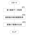
- FIG. 8 is a flowchart showing a process of generating the variable CT image Bc2.
- the teacher data acquisition unit 21 acquires the first teacher data D in which the CT image Bc0 and the correct answer mask Bc1 are paired (step ST1).
- the constraint range acquisition unit 22 acquires the constraint range of the pixel value that can be taken by the pixel belonging to the infarct region A in the CT image Bc0 (step ST2).
- the variation learning image generation unit 23 generates a variation CT image Bc2 by giving variation to the pixel value of the infarct region A of the CT image Bc0 as described above (step ST3), and performs a series of processes. finish.
- the learning image generation device of this exemplary embodiment composed of the teacher data acquisition unit 21, the constraint range acquisition unit 22, and the variation learning image generation unit 23, the learning image generation method of this exemplary embodiment, and the book.
- the learning image generation program of the exemplary embodiment the pixel values of the pixels belonging to the infarct region A are changed within the constraint range of the possible pixel values of the pixels belonging to the infarction region A in the CT image Bc0. It is possible to easily generate a variable CT image Bc2 in which the pixel values of the pixels belonging to the infarct region A are different from those of the CT image Bc0.
- variable value it is possible to generate a plurality of variable CT images Bc2 having different pixel values of the pixels belonging to the infarct region A.
- the limited CT image Bc0 can be used to generate variable CT images Bc2 having different pixel values of the infarct region A, thus covering the diversity of the pixel values of the infarct region A to be segmented. be able to.
- the learning image generation device is configured by the teacher data acquisition unit 21, the constraint range acquisition unit 22, and the variation learning image generation unit 23.
- the technique of the present disclosure is not limited to this, and the constraint range acquisition unit 22 may not be provided.
- the variation learning image generation unit 23 may vary the pixel values of the pixels belonging to the infarct region A based on a predetermined constraint range.
- the variation learning image generation unit 23 varies the pixel values of all the pixels belonging to the infarct region A in the CT image Bc0 by a constant value.
- the pixel values of some of the pixels belonging to the infarct region A may be changed by a constant value.
- FIG. 9 is a diagram for explaining a method of changing the pixel value in the second exemplary embodiment.
- the variation learning image generation unit 23 fluctuates the pixel values of the three pixels shown by the diagonal lines P11, P23, and P41 by a constant value, as an example.
- the number of pixels that fluctuate the pixel value and the number of pixels that fluctuate the pixel value may be set in advance or may be set randomly.
- the variation learning image generation unit 23 varies all the pixel values of the pixels belonging to the infarct region A in the CT image Bc0 by a constant value. I let you.
- the techniques of the present disclosure are not limited to this. For example, it may be changed by a different value for each pixel.
- FIG. 10 is a diagram for explaining a method of changing the pixel value in the third exemplary embodiment.
- the variation learning image generation unit 23 varies the pixel values of the three pixels shown by the diagonal lines P23, P33, and P41 by the first value, as an example. Further, the pixel values of the two pixels of the pixel P11 and the pixel P44 shown by shading are changed by the second value.
- the number of pixels that fluctuate the pixel value with the first value and the number of pixels that fluctuate the pixel value with the first value, and the pixels that fluctuate the pixel value with the second value and the pixel value fluctuate with the second value.
- the number of pixels to be made may be set in advance or may be set randomly.
- the variation learning image generation unit 23 changes the pixel values of the pixels belonging to the infarct region A in the CT image Bc0 to obtain the distribution shown in FIG.
- the graph moves or transforms.
- the techniques of the present disclosure are not limited to this.
- the pixels belonging to the infarct region A may be replaced.
- FIG. 11 is a diagram for explaining a method of changing the pixel value in the fourth exemplary embodiment.
- the variation learning image generation unit 23 replaces the pixel value of the pixel P41 indicated by the diagonal line from the upper right to the lower left with the pixel value of the pixel P44 indicated by shading, as an example. Further, the pixel value of the pixel P33 indicated by the diagonal line from the upper left to the lower right is replaced with the pixel value of the pixel P41 indicated by the diagonal line from the upper right to the lower left. Further, the pixel value of the pixel P44 indicated by shading is replaced with the pixel value of the pixel P33 indicated by a diagonal line extending from the upper left to the lower right.
- the pixel values of the pixels belonging to the infarct region A can be changed while maintaining the graph of the distribution shown in FIG.
- the number of pixels whose pixel values are exchanged and the number of pixels whose pixel values are exchanged may be set in advance or may be set randomly.
- the average and standard deviation of the pixel values of the infarcted region A may be set in advance to determine the normal distribution, and the pixel values may be varied based on the determined normal distribution.
- FIG. 12 is a diagram for explaining a method of changing the pixel value in the fifth exemplary embodiment.
- the variation learning image generation unit 23 sets an average and a standard deviation between the lower limit value L and the upper limit value U of the possible pixel value constraint range of the infarct region A.
- the normal distribution of the pixel values of the infarct region A is determined.
- the variation learning image generation unit 23 fluctuates the pixel value in the infarct region A so that the pixel of each pixel value exists based on the graph of FIG.
- the variation CT image Bc2 generated by the variation learning image generation unit 23 as described above is stored in the storage 13 as image data constituting the second teacher data F.
- FIG. 13 is a diagram for explaining the second teacher data F in which the variable CT image Bc2 and the correct CT image Bc1 are combined.
- the second teacher data F is teacher data in which the variable CT image Bc2 and the correct answer mask Bc1 in which the infarct region A is defined in the CT image Bc0 before the fluctuation of the variable CT image Bc2 are combined. is there.
- the second teacher data F is a combination of the variable CT image Bc2 and the correct mask Bc1 in which the infarct region A is defined in the CT image Bc0 before the fluctuation.
- the correct answer mask Bc3, which newly defines the infarct region A in the variable CT image Bc2, may be paired. However, in the variable CT image Bc2, in the CT image Bc0 before the change, the pixel values of the pixels belonging to the infarct region A are changed within the constraint range of the pixel values that the infarct region A can take.
- the correct answer mask is the same as the correct answer mask Bc3 in which the infarct region A is newly defined in the variable CT image Bc2.
- FIG. 14 is a diagram for explaining a learning method of the learning model.
- the learning model 25 corresponds to the model of the present disclosure.
- the learning model 25 is a model trained to output the infarcted region in the CT image when the CT image to be detected for detecting the infarcted region is input.
- the learning model 25 has a U-Net (U Networks) structure.
- U-Net is one of the full-layer convolutional networks (FCNs) and is a network specialized for image segmentation.
- the learning unit 24 causes the learning model M to learn the infarct region A in the CT image Bc0 by inputting the first teacher data D, that is, the CT image Bc0 and the correct answer mask Bc1 into the learning model M.
- the learning model M is trained so that the region matching the correct mask Bc1 is output as the infarct region A.
- the learning unit 24 causes the learning model M to learn the infarct region A in the variable CT image Bc2 by inputting the second teacher data F, that is, the variable CT image Bc2 and the correct answer mask Bc1 into the learning model M.
- the learning model M is trained so that the region matching the correct mask Bc1 is output as the infarct region A.
- n teacher data are trained by the learning model 25 in order.
- the training model 25 is made to learn the n teacher data again in order for the second time, and the same teacher data is used for a predetermined number of times to repeat the learning model 25. Is being trained.
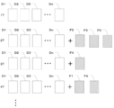
- FIG. 15 is a diagram for explaining a learning method using the first teacher data D and the second teacher data F in the sixth exemplary embodiment.
- the first teacher data D and the second teacher data F are a set of a CT image Bc0 or a variable CT image Bc2 and a correct answer mask Bc1, that is, they are composed of two image data.
- the teacher data D and the second teacher data F are represented by one image for convenience of explanation. It may be expressed in the same manner in the following drawings.
- the learning unit 24 trains the learning model 25 using n first teacher data D1 to Dn at the time of the first learning (1T).
- the learning model 25 is trained by replacing the first teacher data D1 with the second teacher data F1.
- the second teacher data F1 is returned to the first teacher data D1
- the first teacher data D2 is replaced with the second teacher data F2 to train the learning model 25.
- the second teacher data F2 is returned to the first teacher data D2, and the first teacher data D3 is replaced with the second teacher data F3 to train the learning model 25.
- the first teacher data D of one of n first teacher data D1 to Dn is used as the second teacher data for each learning.
- the learning model 25 is trained instead of F.
- FIG. 16 is a flowchart showing the processing performed at the time of learning.
- the teacher data acquisition unit 21 acquires the first teacher data D and the second teacher data F from the image storage server 3 and the storage 13 (step ST11).
- the learning unit 24 trains the learning model 25 as described above using the acquired first teacher data D and the second teacher data F (step ST12), and ends a series of processes.
- the second teacher data F which is a combination of the variable CT image Bc2 and the correct answer mask Bc1, whose pixel values of the pixels belonging to the infarct region A are different from the image Bc0, is used for learning.
- the variable CT image Bc2 in which the infarct region A of the value is defined is used as the teacher data. Therefore, in this exemplary embodiment, it is possible to cover the variety of pixel values of the infarct region A that is the target of segmentation.
- the learning model 25 was trained by replacing one first teacher data D with the second teacher data F each time.
- the two first teacher data D may be replaced with the second teacher data F, or any number of first teacher data D such as three or four may be replaced with the second teacher data F.
- only the predetermined first teacher data D may be replaced with the second teacher data F which is different each time.
- the first teacher data D to be changed to the second teacher data F may be randomly selected.
- the number of the first teacher data D to be changed to the second teacher data F may be randomly determined.
- FIG. 17 is a diagram for explaining a learning method using the first teacher data D and the second teacher data F in the seventh exemplary embodiment.
- the learning unit 24 trains the learning model 25 using n first teacher data D1 to Dn at the time of the first learning (1T).
- the learning model 25 is trained by replacing the first teacher data D1 with the second teacher data F1.
- the second teacher data F1 is returned to the first teacher data D1
- the first teacher data D2 is returned to the second teacher data F2
- the first teacher data D4 is changed to the second teacher.
- the data F4 is replaced with the first teacher data D5 by the second teacher data F5, and the learning model 25 is trained.
- the second teacher data F2 becomes the first teacher data D2
- the second teacher data F4 becomes the first teacher data D4
- the second teacher data F5 becomes the first teacher data D5.
- the learning model 25 is trained by replacing the first teacher data D1 with the second teacher data F1 and the first teacher data D3 with the second teacher data F3.
- the learning model 25 is trained by replacing the first teacher data D with the second teacher data F in each of the second and subsequent learning sessions.
- the learning model 25 may be trained by adding the second teacher data F to the n first teacher data Dn each time.
- FIG. 18 is a diagram for explaining a learning method using the first teacher data D and the second teacher data F in the eighth exemplary embodiment.
- the learning unit 24 trains the learning model 25 using n first teacher data D1 to Dn at the time of the first learning (1T).
- the second teacher data F1 is added to train the learning model 25.
- the second teacher data F2 is added to train the learning model 25.
- the second teacher data F3 is added to train the learning model 25.
- a learning model is added by adding one second teacher data F to the n first teacher data D1 to Dn each time. Learn 25. When n + 1 learning is completed, the process returns to the first learning (1T), and the above learning is repeated until the set number of learning is completed.
- the learning model 25 was trained by adding one second teacher data F each time in the second and subsequent learnings.
- Two second teacher data Fs may be added, or any number of second teacher data Fs, such as three or four, may be added. Further, the second teacher data F to be added may be randomly selected.
- FIG. 19 is a diagram for explaining a learning method using the first teacher data D and the second teacher data F in the ninth exemplary embodiment.
- the learning unit 24 trains the learning model 25 using n first teacher data D1 to Dn at the time of the first learning (1T).
- the learning model 25 is trained by adding the second teacher data F2, the second teacher data F3, and the second teacher data F5.
- the second teacher data F4 is added to train the learning model 25.
- the second teacher data F1 and the second teacher data F4 are added to train the learning model 25.
- a random number of second teacher data Fs are added to n first teacher data D1 to Dn each time.
- the learning model 25 is trained until the set number of learnings is completed.
- FIG. 20 is a diagram for explaining a learning method using the first teacher data D and the second teacher data F in the tenth exemplary embodiment.
- the learning unit 24 uses only n first teacher data D1 to Dn at least once in the second and subsequent learnings, and in the seventh learning in this exemplary embodiment.
- the learning model 25 is trained.
- the number of times the learning model 25 is trained using only n first teacher data D1 to Dn is not limited to the seventh time, and may be any time. Further, the learning model 25 may be trained using only the first teacher data D1 to Dn twice, three times, and n times.
- the disease is infarction, but the technique of the present disclosure is not limited to this, and the disease may be bleeding or the like, for example.
- a CT image is used as the learning image of the present disclosure.
- the technique of the present disclosure is not limited to this, and the learning image of the present disclosure may be another medical image such as a PET image, an ultrasonic image, and an MRI image.
- the MRI image may be any of a T1 image, a T2 image, and a diffusion-weighted image.
- a brain image is used as a medical image, but the present invention is not limited to this.
- the present disclosure can also be applied to discriminate disease areas and areas of interest included in medical images of the chest, abdomen, whole body, limbs, etc. of the human body.
- the learning device 1 includes a learning image generating device, but the technique of the present disclosure is not limited to this, and the learning image generating device may not be included. ..
- the learning device 1 shall include the teacher data acquisition unit 21, so that the teacher data acquisition unit 21 acquires the second teacher data including the variable learning image generated by the external learning generation device. It should be.
- the learning model 25 has a U-Net structure, but the technique of the present disclosure is not limited to this.
- a full-layer convolutional network (FCN) other than U-Net may be used.
- FCN full-layer convolutional network
- various processes such as the teacher data acquisition unit 21, the constraint range acquisition unit 22, the variation learning image generation unit 23, the learning unit 24, the learning model 25, and the display control unit 26 are performed.
- various processors processors shown below can be used.
- the various processors include a CPU, which is a general-purpose processor that executes software (program) and functions as various processing units, and a circuit after manufacturing an FPGA (Field Programmable Gate Array) or the like.
- Dedicated electricity which is a processor with a circuit configuration specially designed to execute specific processing such as programmable logic device (PLD), ASIC (Application Specific Integrated Circuit), which is a processor whose configuration can be changed. Circuits and the like are included.
- One processing unit may be composed of one of these various processors, or a combination of two or more processors of the same type or different types (for example, a combination of a plurality of FPGAs or a combination of a CPU and an FPGA). ) May be configured. Further, a plurality of processing units may be configured by one processor.
- one processor is configured by combining one or more CPUs and software. There is a form in which this processor functions as a plurality of processing units.
- SoC System On Chip
- the various processing units are configured by using one or more of the various processors as a hardware structure.
- circuitry in which circuit elements such as semiconductor elements are combined can be used.
Abstract
This learning image generation device comprises: a teaching data acquisition unit that acquires teaching data in which a learning image is paired with a correct learning image for which the correct region in the learning image is defined; and a variation learning image generation unit that generates a variation learning image in which pixel values of pixels that belong to the correct region in the learning image are varied within a restriction range of pixel values that the pixels that belong to the correct region could take.
Description
本開示は、学習用画像生成装置、方法及びプログラム、並びに学習方法、装置及びプログラムに関する。
The present disclosure relates to a learning image generator, a method and a program, and a learning method, a device and a program.
近年、ディープラーニング(深層学習)を用いた機械学習の技術が注目を集めている。機械学習においては、分類の精度をより向上させるために様々な技術が開発されている。特開2018-5640号公報には、欠陥が写った複数の第1画像を含む第1教師データに基づいて深層学習により畳み込みニューラルネットワーク(Convolutional Neural Network:CNN)を生成し、CNNの中間層に、欠陥が写った複数の第2画像それぞれを入力して、この中間層から複数の第2画像それぞれについての複数種類の特徴量を取得して、複数種類の特徴量を用いてさらに機械学習させることにより、分類精度を向上させたモデルを構築する方法が開示されている。
In recent years, machine learning technology using deep learning has been attracting attention. In machine learning, various techniques have been developed to further improve the accuracy of classification. In Japanese Patent Application Laid-Open No. 2018-5640, a convolutional neural network (CNN) is generated by deep learning based on the first teacher data including a plurality of first images showing defects, and is used as an intermediate layer of the CNN. , Each of the plurality of second images showing defects is input, a plurality of types of feature quantities for each of the plurality of second images are acquired from this intermediate layer, and further machine learning is performed using the plurality of types of feature quantities. As a result, a method for constructing a model with improved classification accuracy is disclosed.
一方、学習用画像と、学習用画像において正解領域が定義された正解学習用画像とを組にした教師データを用いて、End-to-End(エンドツーエンド)深層学習によって、モデルを学習させる方法も知られている。End-to-End深層学習は、入力が与えられてから結果を出力するまで、途中で発生する中間処理を全て学習させる方法である。End-to-End深層学習によって学習された学習モデルにおいては、学習モデルに画像を入力することによって、入力された画像全体をピクセル単位でラベリングすることによりクラス分類を行うセマンティックセグメンテーションを行うことができる。
On the other hand, the model is trained by end-to-end (end-to-end) deep learning using the teacher data in which the learning image and the correct learning image in which the correct answer region is defined in the learning image are paired. The method is also known. End-to-end deep learning is a method of learning all intermediate processes that occur in the process from the time an input is given until the result is output. In the learning model learned by end-to-end deep learning, by inputting an image into the learning model, it is possible to perform semantic segmentation that classifies by labeling the entire input image in pixel units. ..
一般的に、End-to-End深層学習においては、入力側と出力側に各々多くの学習用画像及び正解学習用画像があるほど、より精度の高い出力結果が得られることが知られている。しかしながら、入力対象となる画像が、例えば、脳卒中等の疾患を発症した脳の脳画像である場合、セグメンテーションの対象となる梗塞領域及び出血領域等の疾患領域は、形状、大きさ、及び発症箇所等が不定である。また、疾患の発症からの経過時間によって脳画像中の疾患領域の画素値の値が変化する。そのため、脳画像においては多様な症例が存在することとなり、多様な症例を全てカバーできる程度の学習用画像を用意するのは困難である。
In general, in end-to-end deep learning, it is known that the more learning images and correct answer learning images are on the input side and the output side, the more accurate the output result can be obtained. .. However, when the image to be input is, for example, a brain image of a brain that has developed a disease such as stroke, the disease areas such as the infarcted area and the bleeding area to be segmented have a shape, a size, and an onset site. Etc. are indefinite. In addition, the pixel value of the diseased area in the brain image changes depending on the elapsed time from the onset of the disease. Therefore, there are various cases in the brain image, and it is difficult to prepare a learning image that can cover all the various cases.
本開示は、限られた学習用画像を用いて、セグメンテーションの対象となる画像領域の画素値の多様性をカバーできる、学習用画像生成装置、方法及びプログラム、並びに学習方法、装置及びプログラムを提供する。
The present disclosure provides a learning image generator, a method and a program, and a learning method, a device and a program capable of covering a variety of pixel values of an image region to be segmented by using a limited learning image. To do.
本開示の第1に態様は、学習用画像生成装置であって、学習用画像と、学習用画像において正解領域が定義された正解学習用画像とを組にした教師データを取得する教師データ取得部と、学習用画像において、正解領域に属する画素の取り得る画素値の制約範囲内で、正解領域に属する画素の画素値を変動させた変動学習用画像を生成する変動学習用画像生成部と、を含む。
The first aspect of the present disclosure is a learning image generator, which acquires teacher data in which a learning image and a correct learning image in which a correct area is defined in the learning image are combined. In the learning image, the variation learning image generation unit that generates a variation learning image in which the pixel values of the pixels belonging to the correct answer region are varied within the constraint range of the pixel values that the pixels belonging to the correct answer region can take. ,including.
本開示の第2の態様は、第1の態様において、制約範囲を取得する制約範囲取得部を含んでいてもよい。
The second aspect of the present disclosure may include a constraint range acquisition unit for acquiring a constraint range in the first aspect.
本開示の第3の態様は、第1又は第2の態様において、変動学習用画像生成部は、正解領域に属する画素のうちの1以上の画素の画素値を、一定の値で変動させてもよい。
In the third aspect of the present disclosure, in the first or second aspect, the variation learning image generation unit changes the pixel value of one or more pixels among the pixels belonging to the correct answer region by a constant value. May be good.
本開示の第4の態様は、第1又は第2の態様において、変動学習用画像生成部は、正解領域に属する画素のうちの1以上の画素の画素値を、画素毎に異なる値で変動させてもよい。
In the fourth aspect of the present disclosure, in the first or second aspect, the variation learning image generation unit varies the pixel values of one or more pixels among the pixels belonging to the correct answer region by different values for each pixel. You may let me.
本開示の第5の態様は、第1又は第2の態様において、変動学習用画像生成部は、正解領域に属する画素の画素値に基づいて設定された正規分布に応じて、正解領域に属する画素のうちの1以上の画素の画素値を、画素毎に異なる値で変動させてもよい。
In the fifth aspect of the present disclosure, in the first or second aspect, the variation learning image generation unit belongs to the correct answer region according to the normal distribution set based on the pixel values of the pixels belonging to the correct answer region. The pixel value of one or more of the pixels may be changed by a different value for each pixel.
本開示の第6の態様は、学習用画像生成方法であって、学習用画像と、学習用画像において正解領域が定義された正解学習用画像とを組にした教師データを取得し、学習用画像において、正解領域に属する画素の取り得る画素値の制約範囲内で、正解領域に属する画素の画素値を変動させた変動学習用画像を生成する。
A sixth aspect of the present disclosure is a learning image generation method, in which teacher data in which a learning image and a correct answer learning image in which a correct answer region is defined in the learning image is acquired is acquired and used for learning. In the image, a variation learning image in which the pixel values of the pixels belonging to the correct answer region are varied within the constraint range of the pixel values that the pixels belonging to the correct answer region can take is generated.
本開示の第7の態様は、学習用画像生成プログラムであって、学習用画像と、学習用画像において正解領域が定義された正解学習用画像とを組にした教師データを取得する教師データ取得部と、学習用画像において、正解領域に属する画素の取り得る画素値の制約範囲内で、正解領域に属する画素の画素値を変動させた変動学習用画像を生成する変動学習用画像生成部として、コンピュータを機能させる。
A seventh aspect of the present disclosure is a learning image generation program, which acquires teacher data in which a learning image and a correct learning image in which a correct area is defined in the learning image are combined. As a variable learning image generator that generates a variable learning image in which the pixel values of the pixels belonging to the correct answer region are varied within the constraint range of the pixel values that the pixels belonging to the correct answer region can take in the learning image. , Make the computer work.
本開示の他の態様は、学習用画像生成装置であって、コンピュータに実行させるための命令を記憶するメモリと、記憶された命令を実行するよう構成されたプロセッサとを備え、プロセッサは、学習用画像と、学習用画像において正解領域が定義された正解学習用画像とを組にした教師データを取得し、学習用画像において、正解領域に属する画素の取り得る画素値の制約範囲内で、正解領域に属する画素の画素値を変動させた変動学習用画像を生成する処理を実行する。
Another aspect of the present disclosure is a learning image generator, comprising a memory for storing instructions to be executed by a computer and a processor configured to execute the stored instructions. The teacher data, which is a combination of the image for learning and the image for learning correct answer in which the correct answer region is defined in the learning image, is acquired, and in the learning image, within the constraint range of the pixel value that the pixel belonging to the correct answer region can take. A process of generating a variation learning image in which the pixel values of the pixels belonging to the correct answer region are varied is executed.
本開示の第8の態様は、学習方法であって、学習用画像と、学習用画像において正解領域が定義された正解学習用画像とを組にした1以上の第1教師データ、及び、学習用画像において、正解領域に属する画素の取り得る画素値の制約範囲内で、正解領域に属する画素の画素値を変動させて生成した1以上の変動学習用画像と、1以上の変動学習用画像の各々において変動前の学習用画像において正解領域が定義された正解学習用画像とを組にした1以上の第2教師データを用いてモデルを学習させる。
The eighth aspect of the present disclosure is a learning method, in which one or more first teacher data in which a learning image and a correct answer learning image in which a correct answer region is defined in the learning image are combined, and learning. One or more variation learning images and one or more variation learning images generated by varying the pixel values of the pixels belonging to the correct answer region within the constraint range of the pixel values that the pixels belonging to the correct answer region can take. In each of the above, the model is trained using one or more second teacher data in combination with the correct answer learning image in which the correct answer region is defined in the learning image before the change.
なお、上記の態様において、正解領域に属する画素のうちの1以上の画素の画素値を、一定の値で変動させてもよいし、正解領域に属する画素のうちの1以上の画素の画素値を、画素毎に異なる値で変動させてもよいし、正解領域に属する画素の画素値に基づいて設定された正規分布に応じて、正解領域に属する画素のうちの1以上の画素の画素値を、画素毎に異なる値で変動させてもよい。
In the above aspect, the pixel value of one or more pixels of the pixels belonging to the correct answer region may be changed by a constant value, or the pixel value of one or more pixels of the pixels belonging to the correct answer region may be changed. May be changed by a different value for each pixel, or the pixel value of one or more pixels of the pixels belonging to the correct answer region according to the normal distribution set based on the pixel values of the pixels belonging to the correct answer region. May be changed by a different value for each pixel.
本開示の第9の態様は、第8の態様において、1回目の学習において、複数の第1教師データを用いてモデルを学習させ、2回目以降の学習において、複数の第1教師データのうちの少なくとも1つの第1教師データを第2教師データに換えてモデルを学習させてもよい。
In the ninth aspect of the present disclosure, in the eighth aspect, the model is trained using the plurality of first teacher data in the first learning, and among the plurality of first teacher data in the second and subsequent learnings. The model may be trained by replacing at least one first teacher data of the above with the second teacher data.
本開示の第10の態様は、第8の態様において、1回目の学習において、複数の第1教師データを用いてモデルを学習させ、2回目以降の学習において、少なくとも1つの第2教師データを追加してモデルを学習させてもよい。
In the tenth aspect of the present disclosure, in the eighth aspect, the model is trained using the plurality of first teacher data in the first learning, and at least one second teacher data is used in the second and subsequent learnings. You may additionally train the model.
本開示の第11の態様は、第9又は第10の態様において、2回目以降の学習において、学習の回毎に、使用する第2教師データ及び第2教師データの数の少なくとも一方をランダムに設定してもよい。
In the eleventh aspect of the present disclosure, in the ninth or tenth aspect, at least one of the second teacher data and the second teacher data to be used is randomly selected for each learning in the second and subsequent learnings. It may be set.
本開示の第12の態様は、第9又は第10の態様において、2回目以降の学習において、使用する第2教師データ及び第2教師データの数の少なくとも一方を予め設定してもよい。
In the twelfth aspect of the present disclosure, at least one of the number of the second teacher data and the number of the second teacher data to be used in the second and subsequent learnings may be preset in the ninth or tenth aspect.
本開示の第13の態様は、第9から第12の何れかの態様において、2回目以降の学習において、少なくとも1回、複数の第1教師データのみを用いてモデルを学習させてもよい。
In the thirteenth aspect of the present disclosure, in any of the ninth to twelfth aspects, the model may be trained using only the plurality of first teacher data at least once in the second and subsequent learnings.
本開示の第14の態様は、学習装置であって、学習用画像と、学習用画像において正解領域が定義された正解学習用画像とを組にした1以上の第1教師データ、及び、学習用画像において、正解領域に属する画素の取り得る画素値の制約範囲内で、正解領域に属する画素の画素値を変動させて生成した1以上の変動学習用画像と、1以上の変動学習用画像の各々において変動前の学習用画像において正解領域が定義された正解学習用画像とを組にした1以上の第2教師データとを取得する教師データ取得部と、教師データ取得部により取得された1以上の第1教師データ及び1以上の第2教師データを用いてモデルを学習させる学習部と、を含む。
A fourteenth aspect of the present disclosure is a learning device, in which one or more first teacher data in which a learning image and a correct answer learning image in which a correct answer region is defined in the learning image are paired, and learning. One or more variation learning images and one or more variation learning images generated by varying the pixel values of the pixels belonging to the correct answer region within the constraint range of the pixel values that the pixels belonging to the correct answer region can take. Acquired by the teacher data acquisition unit and the teacher data acquisition unit that acquire one or more second teacher data that is a set of the correct answer learning image in which the correct answer region is defined in the learning image before the change in each of the above. It includes a learning unit that trains a model using one or more first teacher data and one or more second teacher data.
本開示の他の態様は、学習装置であって、コンピュータに実行させるための命令を記憶するメモリと、記憶された命令を実行するよう構成されたプロセッサとを備え、プロセッサは、学習用画像と、学習用画像において正解領域が定義された正解学習用画像とを組にした1以上の第1教師データ、及び、学習用画像において、正解領域に属する画素の取り得る画素値の制約範囲内で、正解領域に属する画素の画素値を変動させて生成した1以上の変動学習用画像と、1以上の変動学習用画像の各々において変動前の学習用画像において正解領域が定義された正解学習用画像とを組にした1以上の第2教師データを用いてモデルを学習させる処理を実行する。
Another aspect of the present disclosure is a learning device comprising a memory for storing instructions to be executed by a computer and a processor configured to execute the stored instructions, wherein the processor is a learning image. , One or more first teacher data in combination with the correct answer learning image in which the correct answer region is defined in the learning image, and within the constraint range of the possible pixel values of the pixels belonging to the correct answer region in the learning image. , One or more variation learning images generated by varying the pixel values of the pixels belonging to the correct answer region, and one or more variation learning images for correct answer learning in which the correct answer region is defined in the learning image before variation. A process of training a model is executed using one or more second teacher data paired with an image.
本開示の第15の態様は、第14の態様において、学習部は、上記の学習方法によってモデルを学習させることができる。
In the fifteenth aspect of the present disclosure, in the fourteenth aspect, the learning unit can train the model by the above learning method.
本開示の第16の態様は、学習プログラムであって、学習用画像と、学習用画像において正解領域が定義された正解学習用画像とを組にした1以上の第1教師データ、及び、学習用画像において、正解領域に属する画素の取り得る画素値の制約範囲内で、正解領域に属する画素の画素値を変動させて生成した1以上の変動学習用画像と、1以上の変動学習用画像の各々において変動前の学習用画像において正解領域が定義された正解学習用画像とを組にした1以上の第2教師データとを取得する教師データ取得部と、教師データ取得部により取得された1以上の第1教師データ及び1以上の第2教師データを用いてモデルを学習させる学習部として、コンピュータを機能させる。
The sixteenth aspect of the present disclosure is a learning program, in which one or more first teacher data in which a learning image and a correct answer learning image in which a correct answer region is defined in the learning image are combined, and learning. One or more variation learning images and one or more variation learning images generated by varying the pixel values of the pixels belonging to the correct answer region within the constraint range of the pixel values that the pixels belonging to the correct answer region can take. In each of the above, the teacher data acquisition unit that acquires one or more second teacher data that is a set of the correct answer learning image in which the correct answer region is defined in the learning image before the change, and the teacher data acquisition unit. The computer functions as a learning unit that trains a model using one or more first teacher data and one or more second teacher data.
上記態様によれば、本開示の学習用画像生成装置、方法及びプログラム、並びに学習方法、装置及びプログラムは、限られた学習用画像を用いて、セグメンテーションの対象となる画像領域の画素値の多様性をカバーできる。
According to the above aspects, the learning image generators, methods and programs of the present disclosure, as well as the learning methods, devices and programs, use a limited number of learning images to vary the pixel values of the image region to be segmented. Can cover sex.
以下、図面を参照して本開示の第1の例示的実施形態について説明する。図1は、本開示の第1の例示的実施形態による学習用画像生成装置及び学習装置を適用した、診断支援システムの概要を示すハードウェア構成図である。図1に示すように、診断支援システムでは、本例示的実施形態による学習装置1、3次元画像撮影装置2、及び画像保管サーバ3が、ネットワーク4を経由して通信可能な状態で接続されている。なお、学習装置1には、本例示的実施形態による学習モデル及び学習用画像生成装置が内包される。
Hereinafter, the first exemplary embodiment of the present disclosure will be described with reference to the drawings. FIG. 1 is a hardware configuration diagram showing an outline of a diagnosis support system to which a learning image generation device and a learning device according to the first exemplary embodiment of the present disclosure are applied. As shown in FIG. 1, in the diagnosis support system, the learning device 1, the three-dimensional image capturing device 2, and the image storage server 3 according to this exemplary embodiment are connected via the network 4 in a communicable state. There is. The learning device 1 includes a learning model and a learning image generation device according to this exemplary embodiment.
3次元画像撮影装置2は、被検体の診断対象となる部位を撮影することにより、その部位を表す3次元画像を生成する装置である。具体的には、3次元画像撮影装置2は、CT(Computed Tomography)装置、MRI(Magnetic Resonance Imaging)装置、及びPET(Positron Emission Tomography)装置等である。この3次元画像撮影装置2により生成された医用画像は、画像保管サーバ3に送信され、保存される。なお、本例示的実施形態においては、被検体である患者の診断対象部位は脳であり、3次元画像撮影装置2はCT装置である。そして、CT装置において、被検体の脳を含む3次元のCT画像Bc0を生成する。
The three-dimensional image capturing device 2 is a device that generates a three-dimensional image representing the site by photographing the site to be diagnosed of the subject. Specifically, the three-dimensional imaging apparatus 2 is a CT (Computed Tomography) apparatus, an MRI (Magnetic Resonance Imaging) apparatus, a PET (Positron Emission Tomography) apparatus, and the like. The medical image generated by the three-dimensional image capturing device 2 is transmitted to the image storage server 3 and stored. In this exemplary embodiment, the diagnosis target site of the patient who is the subject is the brain, and the three-dimensional imaging device 2 is a CT device. Then, in the CT apparatus, a three-dimensional CT image Bc0 including the brain of the subject is generated.
画像保管サーバ3は、各種データを保存して管理するコンピュータであり、大容量外部記憶装置及びデータベース管理用ソフトウェアを備えている。画像保管サーバ3は、有線あるいは無線のネットワーク4を介して他の装置と通信を行い、画像データ等を送受信する。具体的には、画像保管サーバ3は、3次元画像撮影装置2で生成されたCT画像の画像データを含む各種データをネットワーク経由で取得し、大容量外部記憶装置等の記録媒体に保存して管理する。なお、画像データの格納形式及びネットワーク4経由での各装置間の通信は、DICOM(Digital Imaging and Communication in Medicine)等のプロトコルに基づいている。また、本例示的実施形態においては、画像保管サーバ3は、後述する学習モデル25の学習のための学習用画像となるCT画像Bc0を含む第1教師データD(後述する)も保管して管理している。
The image storage server 3 is a computer that stores and manages various data, and is equipped with a large-capacity external storage device and database management software. The image storage server 3 communicates with another device via a wired or wireless network 4 to send and receive image data and the like. Specifically, the image storage server 3 acquires various data including image data of CT images generated by the three-dimensional image capturing device 2 via a network, and stores the data in a recording medium such as a large-capacity external storage device. to manage. The storage format of the image data and the communication between the devices via the network 4 are based on a protocol such as DICOM (Digital Imaging and Communication in Medicine). Further, in the present exemplary embodiment, the image storage server 3 also stores and manages the first teacher data D (described later) including the CT image Bc0 which is a learning image for learning the learning model 25 described later. doing.
本例示的実施形態の学習用画像生成装置及び学習モデルを含む学習装置1は、1台のコンピュータに、本開示の学習用画像生成プログラム及び学習プログラムをインストールしたものである。コンピュータは、診断を行う医師が直接操作するワークステーション又はパーソナルコンピュータでもよいし、それらとネットワークを介して接続されたサーバコンピュータでもよい。学習用画像生成プログラム及び学習プログラムは、DVD(Digital Versatile Disc)あるいはCD-ROM(Compact Disc Read Only Memory)等の記録媒体に記録されて配布され、その記録媒体からコンピュータにインストールされる。又は、ネットワークに接続されたサーバコンピュータの記憶装置、もしくはネットワークストレージに、外部からアクセス可能な状態で記憶され、要求に応じて医師が使用するコンピュータにダウンロードされ、インストールされる。
The learning device 1 including the learning image generation device and the learning model of the present exemplary embodiment is a computer in which the learning image generation program and the learning program of the present disclosure are installed. The computer may be a workstation or personal computer directly operated by the diagnosing doctor, or a server computer connected to them via a network. The learning image generation program and the learning program are recorded and distributed on a recording medium such as a DVD (Digital Versatile Disc) or a CD-ROM (Compact Disc Read Only Memory), and are installed on a computer from the recording medium. Alternatively, it is stored in a storage device of a server computer connected to a network or in a network storage in a state of being accessible from the outside, and is downloaded and installed in a computer used by a doctor upon request.
図2は、コンピュータに学習用画像生成プログラム及び学習プログラムをインストールすることにより実現される本開示の一例示的実施形態である学習装置1の概略構成を示す図である。図2に示すように、学習装置1は、標準的なワークステーションの構成として、CPU(Central Processing Unit)11、メモリ12及びストレージ13を備えている。また、学習装置1には、液晶ディスプレイ等からなる表示部14、並びにキーボード及びマウス等からなる入力部15が接続されている。入力部15は、ユーザによる種々の設定入力を受け付ける。なお、タッチパネルを用いることによって表示部14と入力部15とを兼用するようにしてもよい。
FIG. 2 is a diagram showing a schematic configuration of a learning device 1 which is an exemplary embodiment of the present disclosure realized by installing a learning image generation program and a learning program on a computer. As shown in FIG. 2, the learning device 1 includes a CPU (Central Processing Unit) 11, a memory 12, and a storage 13 as a standard workstation configuration. Further, the learning device 1 is connected to a display unit 14 including a liquid crystal display and the like, and an input unit 15 including a keyboard and a mouse. The input unit 15 receives various setting inputs by the user. By using the touch panel, the display unit 14 and the input unit 15 may be used in combination.
ストレージ13は、ハードディスクドライブ及びSSD(Solid State Drive)等からなる。ストレージ13には、ネットワーク4を経由して画像保管サーバ3から取得した、後述する学習モデル25の学習のための学習用画像となるCT画像Bc0を含む第1教師データD、及び処理に必要な情報を含む各種情報が記憶されている。
The storage 13 includes a hard disk drive, an SSD (Solid State Drive), and the like. The storage 13 contains the first teacher data D including the CT image Bc0, which is a learning image for learning the learning model 25 described later, acquired from the image storage server 3 via the network 4, and is necessary for processing. Various information including information is stored.
また、メモリ12には、学習用画像生成プログラム及び学習プログラムが記憶されている。学習用画像生成プログラムは、CPU11に実行させる処理として、教師データ取得処理と、制約範囲取得処理、変動学習用画像生成処理を規定する。教師データ取得処理では、学習用画像と、学習用画像において正解領域が定義された正解学習用画像とを組にした第1教師データDを取得する。制約範囲取得処理では、学習用画像において、正解領域に属する画素の取り得る画素値の制約範囲を取得する。変動学習用画像生成処理では、制約範囲内で、正解領域に属する画素の画素値を変動させた変動学習用画像を生成する。
Further, the learning image generation program and the learning program are stored in the memory 12. The learning image generation program defines a teacher data acquisition process, a constraint range acquisition process, and a variable learning image generation process as processes to be executed by the CPU 11. In the teacher data acquisition process, the first teacher data D, which is a combination of the learning image and the correct answer learning image in which the correct answer region is defined in the learning image, is acquired. In the constraint range acquisition process, the constraint range of the pixel values that can be taken by the pixels belonging to the correct answer region is acquired in the learning image. In the variation learning image generation process, a variation learning image in which the pixel values of the pixels belonging to the correct answer region are varied within the constraint range is generated.
また、学習プログラムは、CPU11に実行させる処理として、教師データ取得処理、学習処理、判別処理、表示制御処理を規定する。教師データ取得処理では、学習用画像と、学習用画像において正解領域が定義された正解学習用画像とを組にした1以上の第1教師データ、及び、学習用画像において、正解領域に属する画素の取り得る画素値の制約範囲内で、正解領域に属する画素の画素値を変動させて生成した1以上の変動学習用画像と、1以上の変動学習用画像の各々において変動前の学習用画像において正解領域が定義された正解学習用画像とを組にした1以上の第2教師データとを取得する。学習処理では、取得された1以上の第1教師データ及び1以上の第2教師データを用いてモデルを学習させる。判別処理では、学習用画像又は判別の対象となる対象画像が入力された場合に、入力された画像における正解領域を出力する。表示制御処理では、学習用画像、正解学習用画像、及び正解領域等を表示部14に表示する。
Further, the learning program defines teacher data acquisition processing, learning processing, discrimination processing, and display control processing as processing to be executed by the CPU 11. In the teacher data acquisition process, one or more first teacher data in which a learning image and a correct learning image in which a correct area is defined in the learning image are paired, and pixels belonging to the correct area in the learning image. One or more fluctuation learning images generated by fluctuating the pixel values of the pixels belonging to the correct answer region within the constraint range of the pixel values that can be taken, and one or more fluctuation learning images, each of which is a learning image before fluctuation. Acquires one or more second teacher data in combination with the correct answer learning image in which the correct answer region is defined in. In the learning process, the model is trained using the acquired one or more first teacher data and one or more second teacher data. In the discrimination process, when a learning image or a target image to be discriminated is input, the correct answer area in the input image is output. In the display control process, the learning image, the correct answer learning image, the correct answer area, and the like are displayed on the display unit 14.
そして、CPU11がプログラムに従いこれらの処理を実行することで、コンピュータは、教師データ取得部21、制約範囲取得部22、変動学習用画像生成部23、学習部24、学習モデル25、及び表示制御部26として機能する。ここで、教師データ取得部21、制約範囲取得部22、及び変動学習用画像生成部23が、本例示的実施形態の学習用画像生成装置を構成する。
Then, when the CPU 11 executes these processes according to the program, the computer has the teacher data acquisition unit 21, the constraint range acquisition unit 22, the variation learning image generation unit 23, the learning unit 24, the learning model 25, and the display control unit. Functions as 26. Here, the teacher data acquisition unit 21, the constraint range acquisition unit 22, and the variation learning image generation unit 23 constitute the learning image generation device of this exemplary embodiment.
教師データ取得部21は、ネットワークに接続されたインターフェース(不図示)を介して、画像保管サーバ3から、第1教師データDを取得する。図3は、CT画像Bc0と正解マスクBc1とを組にした第1教師データDを説明するための図である。図3に示すように、第1教師データDは、後述する学習モデル25の学習のための学習用画像となるCT画像Bc0及びこのCT画像Bc0において正解領域として梗塞領域Aが定義された正解マスクBc1とを組にした教師データである。なお、図3において、CT画像Bc0は3次元画像であるが、ここでは説明のため、CT画像Bc0の1つの断層面における2次元の断層画像を用いて説明する。また、図3において、正解マスクBc1は、正解領域である梗塞領域Aを白色に塗り潰して描画することにより定義しているが、正解マスクBc1はこれに限られない。例えば、梗塞領域Aの内部を塗り潰すことなく、梗塞領域Aの境界を白色で描画することにより梗塞領域Aを定義してもよい。また、白色以外の色で描画してもよい。また、梗塞領域Aの内部と、梗塞領域Aの外部とを異なる画素値を有する画素で構成した画像とすることにより梗塞領域Aを定義してもよい。
The teacher data acquisition unit 21 acquires the first teacher data D from the image storage server 3 via an interface (not shown) connected to the network. FIG. 3 is a diagram for explaining the first teacher data D in which the CT image Bc0 and the correct answer mask Bc1 are combined. As shown in FIG. 3, the first teacher data D is a CT image Bc0 which is a learning image for learning the learning model 25 described later, and a correct mask in which the infarct region A is defined as the correct region in the CT image Bc0. It is the teacher data combined with Bc1. In FIG. 3, the CT image Bc0 is a three-dimensional image, but here, for the sake of explanation, a two-dimensional tomographic image on one tomographic plane of the CT image Bc0 will be used. Further, in FIG. 3, the correct answer mask Bc1 is defined by painting the infarct region A, which is the correct answer region, in white, but the correct answer mask Bc1 is not limited to this. For example, the infarct region A may be defined by drawing the boundary of the infarct region A in white without filling the inside of the infarct region A. Further, it may be drawn in a color other than white. Further, the infarct region A may be defined by forming an image in which the inside of the infarct region A and the outside of the infarction region A are composed of pixels having different pixel values.
なお、本例示的実施形態のCT画像Bc0は本開示の学習用画像に、本例示的実施形態の正解マスクBc1は本開示の正解学習用画像にそれぞれ対応する。また、CT画像Bc0及び正解マスクBc1、すなわち第1教師データDが既にストレージ13に記憶されている場合には、教師データ取得部21は、ストレージ13から第1教師データDを取得するようにしてもよい。また、教師データ取得部21は、後述する学習モデル25の学習のために、多数の被検体についての第1教師データDを取得する。また、教師データ取得部21は、ストレージ13から後述する第2教師データFを取得する。
The CT image Bc0 of the present exemplary embodiment corresponds to the learning image of the present disclosure, and the correct answer mask Bc1 of the present exemplary embodiment corresponds to the correct answer learning image of the present disclosure. Further, when the CT image Bc0 and the correct answer mask Bc1, that is, the first teacher data D are already stored in the storage 13, the teacher data acquisition unit 21 acquires the first teacher data D from the storage 13. May be good. In addition, the teacher data acquisition unit 21 acquires the first teacher data D for a large number of subjects for learning the learning model 25 described later. Further, the teacher data acquisition unit 21 acquires the second teacher data F, which will be described later, from the storage 13.
表示制御部26は、教師データ取得部21が取得した第1教師データD及び第2教師データFを各々構成するCT画像Bc0、正解マスクBc1、及び変動CT画像Bc2を表示部14に表示させる。
The display control unit 26 causes the display unit 14 to display the CT image Bc0, the correct answer mask Bc1, and the variable CT image Bc2 that constitute the first teacher data D and the second teacher data F acquired by the teacher data acquisition unit 21, respectively.
制約範囲取得部22は、CT画像Bc0において、梗塞領域Aに属する画素の取り得る画素値の制約範囲を取得する。本例示的実施形態においては、CT画像Bc0はCT画像である。一般的に、人間の体の約60%は水からできているため、CT値は水を原点の0、空気の状態を最低値である-1000で各々表現している。空気の-1000はCT画像Bc0上においては黒色で表現されるように設定される。すなわち、2次元画像の場合には画像を構成する各画素、3次元画像の場合には画像を構成する各ボクセルに、白黒の濃淡値(画素値ともいう)が与えられることによりCT画像Bc0が表現される。
The constraint range acquisition unit 22 acquires the constraint range of the pixel value that can be taken by the pixel belonging to the infarct region A in the CT image Bc0. In this exemplary embodiment, the CT image Bc0 is a CT image. Generally, about 60% of the human body is made of water, so the CT value expresses water as the origin of 0 and the state of air as the lowest value of -1000. -1000 of air is set to be represented in black on the CT image Bc0. That is, in the case of a two-dimensional image, each pixel constituting the image, and in the case of a three-dimensional image, each voxel constituting the image is given a black-and-white shading value (also referred to as a pixel value) to obtain a CT image Bc0. Be expressed.
CT画像Bc0上において急性期における梗塞領域Aの取り得る画素値は、20~30程度である。従って、本例示的実施形態において、制約範囲取得部22は、梗塞領域Aの取り得る画素値の制約範囲の下限値Lを20、及び上限値Uを32として取得する。下限値L及び上限値Uの値は、ユーザが入力部15を操作することにより入力される。なお、本例示的実施形態においては、下限値L及び上限値Uの値は、ユーザによって入力されるものとしたが、本開示の技術はこれに限られない。例えば、CT画像、MRI画像、及びPET画像等、画像の種類毎に下限値L及び上限値Uの値を設定した対応表を予めストレージ13に保存しておき、教師データ取得部21が取得した第1教師データDを構成する学習用画像の種類に応じて、上記対応表により下限値L及び上限値Uの値を導出してもよい。また、学習用画像の種類から下限値L及び上限値Uの値を導出することができれば対応表に限られず、例えば式等により導出してもよい。
The possible pixel value of the infarcted region A in the acute phase on the CT image Bc0 is about 20 to 30. Therefore, in the present exemplary embodiment, the constraint range acquisition unit 22 acquires the lower limit value L of the constraint range of the possible pixel values of the infarct region A as 20 and the upper limit value U as 32. The values of the lower limit value L and the upper limit value U are input by the user operating the input unit 15. In the present exemplary embodiment, the values of the lower limit value L and the upper limit value U are input by the user, but the technique of the present disclosure is not limited to this. For example, a correspondence table in which the lower limit value L and the upper limit value U are set for each type of image such as a CT image, an MRI image, and a PET image is stored in the storage 13 in advance, and the teacher data acquisition unit 21 acquires the correspondence table. Depending on the type of the learning image constituting the first teacher data D, the values of the lower limit value L and the upper limit value U may be derived from the above correspondence table. Further, if the values of the lower limit value L and the upper limit value U can be derived from the type of the learning image, the value is not limited to the correspondence table, and may be derived by, for example, an equation.
また、本例示的実施形態においては、正解領域を梗塞領域Aとしたため、制約範囲取得部22は、梗塞領域Aの取り得る画素値の制約範囲の下限値Lを20、及び上限値Uを32として取得した。しかしながら、下限値L及び上限値Uの値、すなわち上記制約範囲は、検出したい対象に応じて適宜設定される。例えば、学習用画像がCT画像の場合、脳画像において脳出血を検出したい場合には、正解領域は出血領域となるため、出血領域の取り得る画素値の制約範囲は、50~80程度となる。
Further, in the present exemplary embodiment, since the correct answer region is the infarct region A, the constraint range acquisition unit 22 sets the lower limit value L of the constraint range of the possible pixel values of the infarct region A to 20 and the upper limit value U to 32. Obtained as. However, the values of the lower limit value L and the upper limit value U, that is, the above-mentioned restriction range are appropriately set according to the target to be detected. For example, when the learning image is a CT image and it is desired to detect cerebral hemorrhage in the brain image, the correct answer region is the bleeding region, so the restriction range of the pixel value that the bleeding region can take is about 50 to 80.
なお、画素値の下限値L及び上限値Uの値は、例えば、学習用画像を撮影した装置の種類、型番、メーカー、撮影した施設、及び検出対象となる病変の種類毎に予め統計をとって、統計によって得られた数値データに基づいて設定するようにしてもよい。
The lower limit value L and the upper limit value U of the pixel values are statistically obtained in advance for each type, model number, manufacturer, imaged facility, and type of lesion to be detected, for example, of the device that captured the learning image. It may be set based on the numerical data obtained by statistics.
変動学習用画像生成部23は、CT画像Bc0において、梗塞領域Aに属する画素の取り得る画素値の制約範囲内で、梗塞領域Aに属する画素の画素値を変動させた変動学習用画像である変動CT画像Bc2を生成する。図4は梗塞領域Aを説明するための図である。なお、図4においては、実際の梗塞領域Aの形状とは異なるが説明を分かり易くするために、梗塞領域Aを4行4列の16個の画素で構成された正方形の領域として説明する。
The variation learning image generation unit 23 is an image for variation learning in which the pixel values of the pixels belonging to the infarct region A are varied within the constraint range of the pixel values that the pixels belonging to the infarction region A can take in the CT image Bc0. A variable CT image Bc2 is generated. FIG. 4 is a diagram for explaining the infarcted region A. In FIG. 4, although the shape of the infarct region A is different from the actual shape, the infarct region A will be described as a square region composed of 16 pixels in 4 rows and 4 columns for the sake of clarity.
梗塞領域Aは、図4に示すように、4行4列に配列されたP11からP44の16個の画素で構成されている。梗塞領域Aを構成する各画素P11~P44は、各々の画素が梗塞領域を示す画素であるため、20以上32以下の画素値となる。図5は梗塞領域Aに属する画素P11~P44の画素値の分布を示すグラフ、図6は梗塞領域Aに属する画素の画素値の変動を説明するためのグラフである。なお、図5及び図6において、横軸は画素値、縦軸は出現度数を示す。
As shown in FIG. 4, the infarct region A is composed of 16 pixels P11 to P44 arranged in 4 rows and 4 columns. Since each pixel P11 to P44 constituting the infarct region A is a pixel indicating an infarct region, the pixel value is 20 or more and 32 or less. FIG. 5 is a graph showing the distribution of pixel values of pixels P11 to P44 belonging to the infarct region A, and FIG. 6 is a graph for explaining fluctuations in pixel values of pixels belonging to the infarct region A. In FIGS. 5 and 6, the horizontal axis represents the pixel value and the vertical axis represents the frequency of appearance.
梗塞領域Aを構成する各画素P11~P44の画素値は、図5に示すように、梗塞領域Aの取り得る画素値の制約範囲の下限値L(20)から上限値U(32)の間で分布する。例えば、梗塞領域Aを構成する各画素P11~P44の画素値の最大値が25である場合には、上記制約範囲の上限値Uの32に到達する「7」の値まで加えることが可能である。そのため、0以上7以下の数値をランダムに選択して、選択された数値を、梗塞領域Aを構成する全ての画素P11~P44の画素値に加える。これにより、図6に示すように、梗塞領域Aに属する画素P11~P44の画素値の点線で示す分布は、加えた数値の分だけ右矢印方向にシフトして、実線で示す分布となる。
As shown in FIG. 5, the pixel values of the pixels P11 to P44 constituting the infarct region A are between the lower limit value L (20) and the upper limit value U (32) of the possible pixel value constraint range of the infarct region A. It is distributed in. For example, when the maximum value of the pixel values of the pixels P11 to P44 constituting the infarct region A is 25, it is possible to add up to the value of "7" that reaches 32 of the upper limit value U of the above restriction range. is there. Therefore, a numerical value of 0 or more and 7 or less is randomly selected, and the selected numerical value is added to the pixel values of all the pixels P11 to P44 constituting the infarct region A. As a result, as shown in FIG. 6, the distribution shown by the dotted line of the pixel values of the pixels P11 to P44 belonging to the infarct region A is shifted in the right arrow direction by the added numerical value, and becomes the distribution shown by the solid line.
一方、梗塞領域Aを構成する各画素P11~P44の画素値の最小値が22である場合には、上記制約範囲の下限値Lの20に到達する「2」の値まで減算することが可能である。そのため、0以上2以下の数値をランダムに選択して、選択された数値を、梗塞領域Aを構成する全ての画素P11~P44の画素値から減算する。これにより、図6に示すように、梗塞領域Aに属する画素P11~P44の画素値の点線で示す分布は、減算した数値の分だけ左矢印方向にシフトして、実線で示す分布となる。
On the other hand, when the minimum value of the pixel values of the pixels P11 to P44 constituting the infarct region A is 22, it is possible to subtract to the value of "2" that reaches 20 of the lower limit value L of the above restriction range. Is. Therefore, a numerical value of 0 or more and 2 or less is randomly selected, and the selected numerical value is subtracted from the pixel values of all the pixels P11 to P44 constituting the infarct region A. As a result, as shown in FIG. 6, the distribution shown by the dotted line of the pixel values of the pixels P11 to P44 belonging to the infarct region A is shifted in the left arrow direction by the subtracted numerical value, and becomes the distribution shown by the solid line.
なお、0以上7以下の数値、及び0以上2以下の数値からランダムに選択する数値の個数は、予め設定された生成すべき変動CT画像Bc2(後述する)の数に基づいて決定される。例えば変動CT画像Bc2を3枚生成したい場合には、0以上7以下の数値、及び0以上2以下の数値からランダムに3つの数値が選択される。なお、生成すべき変動CT画像Bc2の数は、ユーザが入力部15を使用して任意に設定することができる。
The number of numerical values randomly selected from 0 or more and 7 or less and 0 or more and 2 or less is determined based on a preset number of variable CT images Bc2 (described later) to be generated. For example, when it is desired to generate three variable CT images Bc2, three numerical values are randomly selected from a numerical value of 0 or more and 7 or less and a numerical value of 0 or more and 2 or less. The number of variable CT images Bc2 to be generated can be arbitrarily set by the user using the input unit 15.
変動学習用画像生成部23は、選択された数値、すなわちシフト量に基づいて、梗塞領域Aに属する画素の画素値を変動させることにより変動CT画像Bc2を生成する。図7はCT画像Bc0に変動を加えて生成した変動CT画像Bc2を説明するための図である。なお、図7において、変動CT画像Bc2は、CT画像Bc0との違いを明確に表すために、梗塞領域Aの画素値を誇張して変化させている。
The variation learning image generation unit 23 generates a variation CT image Bc2 by varying the pixel values of the pixels belonging to the infarct region A based on the selected numerical value, that is, the shift amount. FIG. 7 is a diagram for explaining a variation CT image Bc2 generated by adding variation to the CT image Bc0. In FIG. 7, the variable CT image Bc2 exaggerates and changes the pixel value of the infarcted region A in order to clearly show the difference from the CT image Bc0.
変動学習用画像生成部23は、図7に示すように、CT画像Bc0において、梗塞領域Aに属する全ての画素の画素値に0以上7以下の数値から選択された数値を加えるか、又はCT画像Bc0における梗塞領域Aに属する全ての画素の画素値から、0以上2以下の数値から選択された数値を減算する。これにより、変動学習用画像生成部23は、CT画像Bc0の梗塞領域Aの画素値に変動を与えた変動CT画像Bc2を生成する。
As shown in FIG. 7, the variation learning image generation unit 23 adds a numerical value selected from a numerical value of 0 or more and 7 or less to the pixel values of all the pixels belonging to the infarct region A in the CT image Bc0, or CT. A value selected from a value of 0 or more and 2 or less is subtracted from the pixel values of all the pixels belonging to the infarcted region A in the image Bc0. As a result, the variation learning image generation unit 23 generates the variation CT image Bc2 in which the pixel value of the infarct region A of the CT image Bc0 is varied.
次いで、本例示的実施形態における変動CT画像Bc2を生成する処理について説明する。図8は変動CT画像Bc2を生成する処理を示すフローチャートである。先ず、教師データ取得部21が、CT画像Bc0と正解マスクBc1とを組にした第1教師データDを取得する(ステップST1)。次に、制約範囲取得部22が、CT画像Bc0において、梗塞領域Aに属する画素の取り得る画素値の制約範囲を取得する(ステップST2)。そして、変動学習用画像生成部23が、CT画像Bc0の梗塞領域Aの画素値に、上述したようにして変動を与えることにより変動CT画像Bc2を生成して(ステップST3)、一連の処理を終了する。
Next, the process of generating the variable CT image Bc2 in this exemplary embodiment will be described. FIG. 8 is a flowchart showing a process of generating the variable CT image Bc2. First, the teacher data acquisition unit 21 acquires the first teacher data D in which the CT image Bc0 and the correct answer mask Bc1 are paired (step ST1). Next, the constraint range acquisition unit 22 acquires the constraint range of the pixel value that can be taken by the pixel belonging to the infarct region A in the CT image Bc0 (step ST2). Then, the variation learning image generation unit 23 generates a variation CT image Bc2 by giving variation to the pixel value of the infarct region A of the CT image Bc0 as described above (step ST3), and performs a series of processes. finish.
教師データ取得部21、制約範囲取得部22、及び変動学習用画像生成部23で構成される本例示的実施形態の学習用画像生成装置、本例示的実施形態の学習用画像生成方法、並びに本例示的実施形態の学習用画像生成プログラムによれば、CT画像Bc0における梗塞領域Aに属する画素の取り得る画素値の制約範囲内で、梗塞領域Aに属する画素の画素値を変動させることにより、容易にCT画像Bc0とは梗塞領域Aに属する画素の画素値が異なる変動CT画像Bc2を生成することができる。また、変動させる値を替えることにより、梗塞領域Aに属する画素の画素値が異なる複数の変動CT画像Bc2を生成することができる。これにより、限られたCT画像Bc0を用いて、梗塞領域Aの画素値の異なる変動CT画像Bc2を生成することができるので、セグメンテーションの対象となる梗塞領域Aの画素値の多様性をカバーすることができる。
The learning image generation device of this exemplary embodiment composed of the teacher data acquisition unit 21, the constraint range acquisition unit 22, and the variation learning image generation unit 23, the learning image generation method of this exemplary embodiment, and the book. According to the learning image generation program of the exemplary embodiment, the pixel values of the pixels belonging to the infarct region A are changed within the constraint range of the possible pixel values of the pixels belonging to the infarction region A in the CT image Bc0. It is possible to easily generate a variable CT image Bc2 in which the pixel values of the pixels belonging to the infarct region A are different from those of the CT image Bc0. Further, by changing the variable value, it is possible to generate a plurality of variable CT images Bc2 having different pixel values of the pixels belonging to the infarct region A. As a result, the limited CT image Bc0 can be used to generate variable CT images Bc2 having different pixel values of the infarct region A, thus covering the diversity of the pixel values of the infarct region A to be segmented. be able to.
なお、上記第1の例示的実施形態においては、教師データ取得部21、制約範囲取得部22、及び変動学習用画像生成部23により学習用画像生成装置が構成されるものとした。しかしながら、本開示の技術はこれに限られず、制約範囲取得部22を備えていなくてもよい。この場合、変動学習用画像生成部23は、予め定められた制約範囲に基づいて、梗塞領域Aに属する画素の画素値を変動させればよい。
In the first exemplary embodiment, the learning image generation device is configured by the teacher data acquisition unit 21, the constraint range acquisition unit 22, and the variation learning image generation unit 23. However, the technique of the present disclosure is not limited to this, and the constraint range acquisition unit 22 may not be provided. In this case, the variation learning image generation unit 23 may vary the pixel values of the pixels belonging to the infarct region A based on a predetermined constraint range.
また、上記第1の例示的実施形態においては、変動学習用画像生成部23は、CT画像Bc0において梗塞領域Aに属する全ての画素の画素値を一定の値で変動させたが、本開示の技術はこれに限られない。例えば、梗塞領域Aに属する画素のうちの一部の画素の画素値を一定の値で変動させてもよい。図9は第2の例示的実施形態における画素値の変動方法を説明するための図である。
Further, in the first exemplary embodiment, the variation learning image generation unit 23 varies the pixel values of all the pixels belonging to the infarct region A in the CT image Bc0 by a constant value. Technology is not limited to this. For example, the pixel values of some of the pixels belonging to the infarct region A may be changed by a constant value. FIG. 9 is a diagram for explaining a method of changing the pixel value in the second exemplary embodiment.
変動学習用画像生成部23は、図9に示すように、一例として、斜線で示す画素P11、画素P23、及び画素P41の3つの画素の画素値を一定の値で変動させる。なお、画素値を変動させる画素及び画素値を変動させる画素の個数は予め設定してもよいし、ランダムに設定されるようにしてもよい。
As shown in FIG. 9, the variation learning image generation unit 23 fluctuates the pixel values of the three pixels shown by the diagonal lines P11, P23, and P41 by a constant value, as an example. The number of pixels that fluctuate the pixel value and the number of pixels that fluctuate the pixel value may be set in advance or may be set randomly.
また、上記第1の例示的実施形態及び第2の例示的実施形態においては、変動学習用画像生成部23は、CT画像Bc0において梗塞領域Aに属する画素の画素値を全て一定の値で変動させた。しかしながら、本開示の技術はこれに限られない。例えば、画素毎に異なる値で変動させてもよい。図10は第3の例示的実施形態における画素値の変動方法を説明するための図である。
Further, in the first exemplary embodiment and the second exemplary embodiment, the variation learning image generation unit 23 varies all the pixel values of the pixels belonging to the infarct region A in the CT image Bc0 by a constant value. I let you. However, the techniques of the present disclosure are not limited to this. For example, it may be changed by a different value for each pixel. FIG. 10 is a diagram for explaining a method of changing the pixel value in the third exemplary embodiment.
変動学習用画像生成部23は、図10に示すように、一例として、斜線で示す画素P23、画素P33、及び画素P41の3つの画素の画素値を第1の値で変動させる。また、網掛けで示す画素P11及び画素P44の2つの画素の画素値を第2の値で変動させる。
なお、第1の値で画素値を変動させる画素及び第1の値で画素値を変動させる画素の個数、並びに第2の値で画素値を変動させる画素及び第2の値で画素値を変動させる画素の個数は予め設定してもよいし、ランダムに設定されるようにしてもよい。 As shown in FIG. 10, the variation learningimage generation unit 23 varies the pixel values of the three pixels shown by the diagonal lines P23, P33, and P41 by the first value, as an example. Further, the pixel values of the two pixels of the pixel P11 and the pixel P44 shown by shading are changed by the second value.
The number of pixels that fluctuate the pixel value with the first value and the number of pixels that fluctuate the pixel value with the first value, and the pixels that fluctuate the pixel value with the second value and the pixel value fluctuate with the second value. The number of pixels to be made may be set in advance or may be set randomly.
なお、第1の値で画素値を変動させる画素及び第1の値で画素値を変動させる画素の個数、並びに第2の値で画素値を変動させる画素及び第2の値で画素値を変動させる画素の個数は予め設定してもよいし、ランダムに設定されるようにしてもよい。 As shown in FIG. 10, the variation learning
The number of pixels that fluctuate the pixel value with the first value and the number of pixels that fluctuate the pixel value with the first value, and the pixels that fluctuate the pixel value with the second value and the pixel value fluctuate with the second value. The number of pixels to be made may be set in advance or may be set randomly.
また、上記第1から第3の例示的実施形態においては、変動学習用画像生成部23は、CT画像Bc0において梗塞領域Aに属する画素の画素値を変動させることにより、図5に示す分布のグラフが移動又は変形する。しかしながら、本開示の技術はこれに限られない。例えば、梗塞領域Aに属する画素を入れ換えてもよい。図11は第4の例示的実施形態における画素値の変動方法を説明するための図である。
Further, in the first to third exemplary embodiments, the variation learning image generation unit 23 changes the pixel values of the pixels belonging to the infarct region A in the CT image Bc0 to obtain the distribution shown in FIG. The graph moves or transforms. However, the techniques of the present disclosure are not limited to this. For example, the pixels belonging to the infarct region A may be replaced. FIG. 11 is a diagram for explaining a method of changing the pixel value in the fourth exemplary embodiment.
変動学習用画像生成部23は、図11に示すように、一例として、右上から左下へ向かう斜線で示す画素P41の画素値を、網掛けで示す画素P44の画素値に替える。また、左上から右下へ向かう斜線で示す画素P33の画素値を、右上から左下へ向かう斜線で示す画素P41の画素値に替える。また、網掛けで示す画素P44の画素値を左上から右下へ向かう斜線で示す画素P33の画素値に替える。本例示的実施形態においては、梗塞領域Aに属する画素を入れ替えただけなので、図5に示す分布のグラフを保持したままで梗塞領域Aに属する画素の画素値を変動させることができる。なお、画素値を入れ替える画素及び画素値を入れ替える画素の個数は予め設定してもよいし、ランダムに設定されるようにしてもよい。
As shown in FIG. 11, the variation learning image generation unit 23 replaces the pixel value of the pixel P41 indicated by the diagonal line from the upper right to the lower left with the pixel value of the pixel P44 indicated by shading, as an example. Further, the pixel value of the pixel P33 indicated by the diagonal line from the upper left to the lower right is replaced with the pixel value of the pixel P41 indicated by the diagonal line from the upper right to the lower left. Further, the pixel value of the pixel P44 indicated by shading is replaced with the pixel value of the pixel P33 indicated by a diagonal line extending from the upper left to the lower right. In this exemplary embodiment, since the pixels belonging to the infarct region A are simply replaced, the pixel values of the pixels belonging to the infarct region A can be changed while maintaining the graph of the distribution shown in FIG. The number of pixels whose pixel values are exchanged and the number of pixels whose pixel values are exchanged may be set in advance or may be set randomly.
また、予め梗塞領域Aの画素値の平均と標準偏差とを設定して、正規分布を決定し、決定した正規分布に基づいて画素値を変動させてもよい。図12は第5の例示的実施形態における画素値の変動方法を説明するための図である。変動学習用画像生成部23は、図12に示すように、梗塞領域Aの取り得る画素値の制約範囲の下限値Lから上限値Uの間で、平均と標準偏差とを設定することにより、梗塞領域Aの画素値の正規分布を決定する。変動学習用画像生成部23は、梗塞領域Aにおいて図12のグラフに基づいて、各画素値の画素が存在するように、画素値を変動させる。
Alternatively, the average and standard deviation of the pixel values of the infarcted region A may be set in advance to determine the normal distribution, and the pixel values may be varied based on the determined normal distribution. FIG. 12 is a diagram for explaining a method of changing the pixel value in the fifth exemplary embodiment. As shown in FIG. 12, the variation learning image generation unit 23 sets an average and a standard deviation between the lower limit value L and the upper limit value U of the possible pixel value constraint range of the infarct region A. The normal distribution of the pixel values of the infarct region A is determined. The variation learning image generation unit 23 fluctuates the pixel value in the infarct region A so that the pixel of each pixel value exists based on the graph of FIG.
以上のようにして変動学習用画像生成部23により生成された変動CT画像Bc2は、第2教師データFを構成する画像データとしてストレージ13に記憶される。図13は変動CT画像Bc2と正解CT画像Bc1とを組にした第2教師データFを説明するための図である。第2教師データFは、図13に示すように、変動CT画像Bc2と、変動CT画像Bc2の変動前のCT画像Bc0において梗塞領域Aが定義された正解マスクBc1とを組にした教師データである。なお、本例示的実施形態において第2教師データFは、変動CT画像Bc2と変動前のCT画像Bc0において梗塞領域Aが定義された正解マスクBc1とを組にしたが、変動CT画像Bc2と、変動CT画像Bc2において新たに梗塞領域Aを定義した正解マスクBc3とを組にしてもよい。ただし、変動CT画像Bc2は、変動前のCT画像Bc0において、梗塞領域Aに属する画素の画素値を梗塞領域Aの取り得る画素値の制約範囲内において変動させているので、正解マスクBc1と、変動CT画像Bc2において新たに梗塞領域Aを定義した正解マスクBc3とは同じ正解マスクとなる。
The variation CT image Bc2 generated by the variation learning image generation unit 23 as described above is stored in the storage 13 as image data constituting the second teacher data F. FIG. 13 is a diagram for explaining the second teacher data F in which the variable CT image Bc2 and the correct CT image Bc1 are combined. As shown in FIG. 13, the second teacher data F is teacher data in which the variable CT image Bc2 and the correct answer mask Bc1 in which the infarct region A is defined in the CT image Bc0 before the fluctuation of the variable CT image Bc2 are combined. is there. In the present exemplary embodiment, the second teacher data F is a combination of the variable CT image Bc2 and the correct mask Bc1 in which the infarct region A is defined in the CT image Bc0 before the fluctuation. The correct answer mask Bc3, which newly defines the infarct region A in the variable CT image Bc2, may be paired. However, in the variable CT image Bc2, in the CT image Bc0 before the change, the pixel values of the pixels belonging to the infarct region A are changed within the constraint range of the pixel values that the infarct region A can take. The correct answer mask is the same as the correct answer mask Bc3 in which the infarct region A is newly defined in the variable CT image Bc2.
次に、図2に戻り、学習部24は、教師データ取得部21により取得された1以上の第1教師データD及び1以上の第2教師データFを用いて学習モデル25を学習させる。図14は学習モデルの学習方法を説明するための図である。なお、本例示的実施形態において学習モデル25は、本開示のモデルに対応する。
Next, returning to FIG. 2, the learning unit 24 trains the learning model 25 using one or more first teacher data D and one or more second teacher data F acquired by the teacher data acquisition unit 21. FIG. 14 is a diagram for explaining a learning method of the learning model. In this exemplary embodiment, the learning model 25 corresponds to the model of the present disclosure.
学習モデル25は、梗塞領域を検出する対象となるCT画像が入力された場合に、CT画像における梗塞領域を出力するように学習されたモデルである。本例示的実施形態においては、学習モデル25は、U-Net(U Networks)の構造を有する。U-Netは、全層畳み込みネットワーク(Fully Convolution Network;FCN)の1つであり、画像のセグメンテーションに特化したネットワークである。
The learning model 25 is a model trained to output the infarcted region in the CT image when the CT image to be detected for detecting the infarcted region is input. In this exemplary embodiment, the learning model 25 has a U-Net (U Networks) structure. U-Net is one of the full-layer convolutional networks (FCNs) and is a network specialized for image segmentation.
学習部24は、図14に示すように、第1教師データDすなわちCT画像Bc0及び正解マスクBc1を学習モデルMに入力することにより、学習モデルMにCT画像Bc0における梗塞領域Aを学習させる。これにより、CT画像Bc0が入力された場合に、正解マスクBc1と一致する領域が梗塞領域Aとして出力されるように学習モデルMを学習させる。また、学習部24は、第2教師データFすなわち変動CT画像Bc2及び正解マスクBc1を学習モデルMに入力することにより、学習モデルMに変動CT画像Bc2における梗塞領域Aを学習させる。これにより、変動CT画像Bc2が入力された場合に、正解マスクBc1と一致する領域が梗塞領域Aとして出力されるように学習モデルMを学習させる。
As shown in FIG. 14, the learning unit 24 causes the learning model M to learn the infarct region A in the CT image Bc0 by inputting the first teacher data D, that is, the CT image Bc0 and the correct answer mask Bc1 into the learning model M. As a result, when the CT image Bc0 is input, the learning model M is trained so that the region matching the correct mask Bc1 is output as the infarct region A. Further, the learning unit 24 causes the learning model M to learn the infarct region A in the variable CT image Bc2 by inputting the second teacher data F, that is, the variable CT image Bc2 and the correct answer mask Bc1 into the learning model M. As a result, when the variable CT image Bc2 is input, the learning model M is trained so that the region matching the correct mask Bc1 is output as the infarct region A.
次に、1以上の第1教師データD及び1以上の第2教師データFを用いた学習モデル25の学習方法について説明する。一般的に学習モデル25を学習させる場合には、例えばn個の教師データを順に学習モデル25に学習させる。そして、n個の教師データが全て学習されると、2回目として再度n個の教師データを順に学習モデル25に学習させて、予め定められた回数、同じ教師データを使用して繰り返し学習モデル25に学習させることが行われている。
Next, a learning method of the learning model 25 using one or more first teacher data D and one or more second teacher data F will be described. Generally, when the learning model 25 is trained, for example, n teacher data are trained by the learning model 25 in order. Then, when all n teacher data are learned, the training model 25 is made to learn the n teacher data again in order for the second time, and the same teacher data is used for a predetermined number of times to repeat the learning model 25. Is being trained.
本例示的実施形態においては、n個の第1教師データD1~Dnを用いて学習モデル25を学習させる際に、1回目はn個の第1教師データD1~Dnを用いて学習モデル25を学習させる。次に、2回目以降は、n個の第1教師データD1~Dnのうちの少なくとも1つの第1教師データDを第2教師データFに換えて学習モデル25を学習させる。図15は第6の例示的実施形態における第1教師データD及び第2教師データFを用いた学習方法を説明するための図である。なお、第1教師データD及び第2教師データFは、CT画像Bc0又は変動CT画像Bc2と、正解マスクBc1との組で、すなわち2つの画像データで構成されているが、図15において第1教師データD及び第2教師データFは説明の都合上、1枚の画像で表してある。なお、以下の図面においても同様に表すことがある。
In this exemplary embodiment, when the learning model 25 is trained using the n first teacher data D1 to Dn, the learning model 25 is first trained using the n first teacher data D1 to Dn. Let them learn. Next, from the second time onward, at least one of the n first teacher data D1 to Dn is replaced with the second teacher data F to train the learning model 25. FIG. 15 is a diagram for explaining a learning method using the first teacher data D and the second teacher data F in the sixth exemplary embodiment. The first teacher data D and the second teacher data F are a set of a CT image Bc0 or a variable CT image Bc2 and a correct answer mask Bc1, that is, they are composed of two image data. The teacher data D and the second teacher data F are represented by one image for convenience of explanation. It may be expressed in the same manner in the following drawings.
学習部24は、図15に示すように、1回目の学習時(1T)には、n個の第1教師データD1~Dnを用いて学習モデル25を学習させる。2回目の学習時(2T)には、第1教師データD1を第2教師データF1に換えて学習モデル25を学習させる。3回目の学習時(3T)には、第2教師データF1を第1教師データD1に戻して、かつ、第1教師データD2を第2教師データF2に換えて学習モデル25を学習させる。さらに4回目の学習時(4T)には、第2教師データF2を第1教師データD2に戻して、かつ、第1教師データD3を第2教師データF3に換えて学習モデル25を学習させる。
As shown in FIG. 15, the learning unit 24 trains the learning model 25 using n first teacher data D1 to Dn at the time of the first learning (1T). At the time of the second learning (2T), the learning model 25 is trained by replacing the first teacher data D1 with the second teacher data F1. At the time of the third learning (3T), the second teacher data F1 is returned to the first teacher data D1, and the first teacher data D2 is replaced with the second teacher data F2 to train the learning model 25. Further, at the time of the fourth learning (4T), the second teacher data F2 is returned to the first teacher data D2, and the first teacher data D3 is replaced with the second teacher data F3 to train the learning model 25.
このように、第6の例示的実施形態においては、2回目以降の学習において、回毎に、n個の第1教師データD1~Dnのうちの1つの第1教師データDを第2教師データFに換えて学習モデル25を学習させる。n+1回の学習が終了すると、1回目の学習(1T)に戻り、設定された回数の学習が終了するまで上記学習を繰り返し行う。
As described above, in the sixth exemplary embodiment, in the second and subsequent learnings, the first teacher data D of one of n first teacher data D1 to Dn is used as the second teacher data for each learning. The learning model 25 is trained instead of F. When n + 1 learning is completed, the process returns to the first learning (1T), and the above learning is repeated until the set number of learning is completed.
次いで、第6の例示的実施形態における一連の処理について説明する。図16は学習時に行われる処理を示すフローチャートである。先ず、教師データ取得部21が、画像保管サーバ3及びストレージ13から第1教師データD及び第2教師データFを取得する(ステップST11)。次いで、学習部24が、取得した第1教師データD及び第2教師データFを用いて、学習モデル25を上述のようにして学習させて(ステップST12)、一連の処理を終了する。
Next, a series of processes in the sixth exemplary embodiment will be described. FIG. 16 is a flowchart showing the processing performed at the time of learning. First, the teacher data acquisition unit 21 acquires the first teacher data D and the second teacher data F from the image storage server 3 and the storage 13 (step ST11). Next, the learning unit 24 trains the learning model 25 as described above using the acquired first teacher data D and the second teacher data F (step ST12), and ends a series of processes.
第6の例示的実施形態においては、CT画像Bc0における梗塞領域Aに属する画素の取り得る画素値の制約範囲内で、梗塞領域Aに属する画素の画素値を変動させることにより生成された、CT画像Bc0とは梗塞領域Aに属する画素の画素値が異なる変動CT画像Bc2と正解マスクBc1とを組にした第2教師データFを学習に使用する。このように、第1教師データDのみを使用して学習モデル25を学習させるよりも、第2教師データFを使用することにより、第1教師データDの梗塞領域Aの画素値とは異なる画素値の梗塞領域Aが定義された変動CT画像Bc2が教師データとして使用される。したがって、本例示的実施形態では、セグメンテーションの対象となる梗塞領域Aの画素値の多様性をカバーすることができる。
In the sixth exemplary embodiment, the CT generated by varying the pixel values of the pixels belonging to the infarcted region A within the constrained range of possible pixel values of the pixels belonging to the infarcted region A in the CT image Bc0. The second teacher data F, which is a combination of the variable CT image Bc2 and the correct answer mask Bc1, whose pixel values of the pixels belonging to the infarct region A are different from the image Bc0, is used for learning. In this way, rather than training the learning model 25 using only the first teacher data D, by using the second teacher data F, pixels different from the pixel values of the infarct region A of the first teacher data D are used. The variable CT image Bc2 in which the infarct region A of the value is defined is used as the teacher data. Therefore, in this exemplary embodiment, it is possible to cover the variety of pixel values of the infarct region A that is the target of segmentation.
なお、第6の例示的実施形態においては、2回目以降の学習において、回毎に1つの第1教師データDを第2教師データFに換えて学習モデル25を学習させたが、本開示の技術はこれに限られない。2つの第1教師データDを第2教師データFに換えてもよいし、3つ、4つ等、任意の数の第1教師データDを第2教師データFに替えることができる。また、予め定められた第1教師データDのみを回毎に異なる第2教師データFに換えてもよい。また、第2教師データFに変更する第1教師データDはランダムに選択されるようにしてもよい。また、第2教師データFに変更する第1教師データDの個数はランダムに決定されるようにしてもよい。また、第2教師データFに変更する第1教師データD及び第2教師データFに変更する第1教師データDの個数の両方を、ランダムに決定するようにしてもよい。図17は第7の例示的実施形態における第1教師データD及び第2教師データFを用いた学習方法を説明するための図である。
In the sixth exemplary embodiment, in the second and subsequent learnings, the learning model 25 was trained by replacing one first teacher data D with the second teacher data F each time. Technology is not limited to this. The two first teacher data D may be replaced with the second teacher data F, or any number of first teacher data D such as three or four may be replaced with the second teacher data F. Further, only the predetermined first teacher data D may be replaced with the second teacher data F which is different each time. Further, the first teacher data D to be changed to the second teacher data F may be randomly selected. Further, the number of the first teacher data D to be changed to the second teacher data F may be randomly determined. Further, both the number of the first teacher data D to be changed to the second teacher data F and the number of the first teacher data D to be changed to the second teacher data F may be randomly determined. FIG. 17 is a diagram for explaining a learning method using the first teacher data D and the second teacher data F in the seventh exemplary embodiment.
学習部24は、図17に示すように、1回目の学習時(1T)には、n個の第1教師データD1~Dnを用いて学習モデル25を学習させる。2回目の学習時(2T)には、第1教師データD1を第2教師データF1に換えて学習モデル25を学習させる。3回目の学習時(3T)には、第2教師データF1を第1教師データD1に戻して、かつ、第1教師データD2を第2教師データF2に、第1教師データD4を第2教師データF4に、第1教師データD5を第2教師データF5に、それぞれ換えて学習モデル25を学習させる。さらに4回目の学習時(4T)には、第2教師データF2を第1教師データD2に、第2教師データF4を第1教師データD4に、第2教師データF5を第1教師データD5に、それぞれ戻して、かつ、第1教師データD1を第2教師データF1に、第1教師データD3を第2教師データF3に換えて学習モデル25を学習させる。
As shown in FIG. 17, the learning unit 24 trains the learning model 25 using n first teacher data D1 to Dn at the time of the first learning (1T). At the time of the second learning (2T), the learning model 25 is trained by replacing the first teacher data D1 with the second teacher data F1. At the time of the third learning (3T), the second teacher data F1 is returned to the first teacher data D1, the first teacher data D2 is returned to the second teacher data F2, and the first teacher data D4 is changed to the second teacher. The data F4 is replaced with the first teacher data D5 by the second teacher data F5, and the learning model 25 is trained. Further, at the time of the fourth learning (4T), the second teacher data F2 becomes the first teacher data D2, the second teacher data F4 becomes the first teacher data D4, and the second teacher data F5 becomes the first teacher data D5. The learning model 25 is trained by replacing the first teacher data D1 with the second teacher data F1 and the first teacher data D3 with the second teacher data F3.
なお、第6の例示的実施形態及び第7の例示的実施形態においては、2回目以降の学習において、回毎に第1教師データDを第2教師データFに換えて学習モデル25を学習させたが、本開示の技術はこれに限られない。回毎にn個の第1教師データDnに第2教師データFを追加して学習モデル25を学習させてもよい。図18は第8の例示的実施形態における第1教師データD及び第2教師データFを用いた学習方法を説明するための図である。
In the sixth exemplary embodiment and the seventh exemplary embodiment, the learning model 25 is trained by replacing the first teacher data D with the second teacher data F in each of the second and subsequent learning sessions. However, the technique of the present disclosure is not limited to this. The learning model 25 may be trained by adding the second teacher data F to the n first teacher data Dn each time. FIG. 18 is a diagram for explaining a learning method using the first teacher data D and the second teacher data F in the eighth exemplary embodiment.
学習部24は、図18に示すように、1回目の学習時(1T)には、n個の第1教師データD1~Dnを用いて学習モデル25を学習させる。2回目の学習時(2T)には、第2教師データF1を加えて学習モデル25を学習させる。3回目の学習時(3T)には、第2教師データF2を加えて学習モデル25を学習させる。さらに4回目の学習時(4T)には、第2教師データF3を加えて学習モデル25を学習させる。
As shown in FIG. 18, the learning unit 24 trains the learning model 25 using n first teacher data D1 to Dn at the time of the first learning (1T). At the time of the second learning (2T), the second teacher data F1 is added to train the learning model 25. At the time of the third learning (3T), the second teacher data F2 is added to train the learning model 25. Further, at the time of the fourth learning (4T), the second teacher data F3 is added to train the learning model 25.
このように、第8の例示的実施形態においては、2回目以降の学習において、回毎に、n個の第1教師データD1~Dnに、さらに第2教師データFを1つ加えて学習モデル25を学習させる。n+1回の学習が終了すると、1回目の学習(1T)に戻り、設定された回数の学習が終了するまで上記学習を繰り返し行う。
As described above, in the eighth exemplary embodiment, in the second and subsequent learnings, a learning model is added by adding one second teacher data F to the n first teacher data D1 to Dn each time. Learn 25. When n + 1 learning is completed, the process returns to the first learning (1T), and the above learning is repeated until the set number of learning is completed.
なお、第8の例示的実施形態においては、2回目以降の学習において、回毎に1つの第2教師データF加えて学習モデル25を学習させた。しかしながら、本開示の技術はこれに限られない。2つの第2教師データFを加えてもよいし、3つ、4つ等、任意の数の第2教師データFを加えることができる。また、加える第2教師データFはランダムに選択されるようにしてもよい。図19は第9の例示的実施形態における第1教師データD及び第2教師データFを用いた学習方法を説明するための図である。
In the eighth exemplary embodiment, the learning model 25 was trained by adding one second teacher data F each time in the second and subsequent learnings. However, the techniques of the present disclosure are not limited to this. Two second teacher data Fs may be added, or any number of second teacher data Fs, such as three or four, may be added. Further, the second teacher data F to be added may be randomly selected. FIG. 19 is a diagram for explaining a learning method using the first teacher data D and the second teacher data F in the ninth exemplary embodiment.
学習部24は、図19に示すように、1回目の学習時(1T)には、n個の第1教師データD1~Dnを用いて学習モデル25を学習させる。2回目の学習時(2T)には、第2教師データF2、第2教師データF3、及び第2教師データF5を加えて学習モデル25を学習させる。3回目の学習時(3T)には、第2教師データF4を加えて学習モデル25を学習させる。さらに4回目の学習時(4T)には、第2教師データF1及び第2教師データF4を加えて学習モデル25を学習させる。
As shown in FIG. 19, the learning unit 24 trains the learning model 25 using n first teacher data D1 to Dn at the time of the first learning (1T). At the time of the second learning (2T), the learning model 25 is trained by adding the second teacher data F2, the second teacher data F3, and the second teacher data F5. At the time of the third learning (3T), the second teacher data F4 is added to train the learning model 25. Further, at the time of the fourth learning (4T), the second teacher data F1 and the second teacher data F4 are added to train the learning model 25.
このように、第9の例示的実施形態においては、2回目以降の学習において、回毎に、n個の第1教師データD1~Dnに、さらに第2教師データFをランダムの個数加えて、設定された回数の学習が終了するまで学習モデル25を学習させる。
As described above, in the ninth exemplary embodiment, in the second and subsequent learnings, a random number of second teacher data Fs are added to n first teacher data D1 to Dn each time. The learning model 25 is trained until the set number of learnings is completed.
なお、本開示の学習モデル25の学習方法は上記第6~第9の例示的実施形態に示す学習方法に限られない。図20は第10の例示的実施形態における第1教師データD及び第2教師データFを用いた学習方法を説明するための図である。
The learning method of the learning model 25 of the present disclosure is not limited to the learning method shown in the sixth to ninth exemplary embodiments. FIG. 20 is a diagram for explaining a learning method using the first teacher data D and the second teacher data F in the tenth exemplary embodiment.
学習部24は、図20に示すように、2回目以降の学習において、少なくとも1回、本例示的実施形態においては7回目の学習において、n個の第1教師データD1~Dnのみを用いて学習モデル25を学習させる。なお、n個の第1教師データD1~Dnのみを用いて学習モデル25を学習させる回は、7回目に限られず何れの回であってもよい。また、2回、3回とn個の第1教師データD1~Dnのみを用いて学習モデル25を学習させてもよい。
As shown in FIG. 20, the learning unit 24 uses only n first teacher data D1 to Dn at least once in the second and subsequent learnings, and in the seventh learning in this exemplary embodiment. The learning model 25 is trained. The number of times the learning model 25 is trained using only n first teacher data D1 to Dn is not limited to the seventh time, and may be any time. Further, the learning model 25 may be trained using only the first teacher data D1 to Dn twice, three times, and n times.
なお、上記例示的実施形態においては、疾患を梗塞としたが、本開示の技術はこれに限られず、例えば疾患は出血等であってもよい。
In the above exemplary embodiment, the disease is infarction, but the technique of the present disclosure is not limited to this, and the disease may be bleeding or the like, for example.
また、上記例示的実施形態においては、本開示の学習用画像としてCT画像を用いている。しかしながら、本開示の技術はこれに限定されるものではなく、本開示の学習用画像は例えばPET画像、超音波画像、及びMRI画像等の他の医用画像であってもよい。MRI画像は、T1画像、T2画像、及び拡散強調画像の何れの画像であってもよい。
Further, in the above exemplary embodiment, a CT image is used as the learning image of the present disclosure. However, the technique of the present disclosure is not limited to this, and the learning image of the present disclosure may be another medical image such as a PET image, an ultrasonic image, and an MRI image. The MRI image may be any of a T1 image, a T2 image, and a diffusion-weighted image.
また、上記例示的実施形態においては、医用画像として脳画像を用いているが、これに限定されるものではない。例えば、人体の胸部、腹部、全身及び四肢等の医用画像に含まれる疾患領域及び関心領域等を判別する場合にも、本開示を適用することができる。
Further, in the above exemplary embodiment, a brain image is used as a medical image, but the present invention is not limited to this. For example, the present disclosure can also be applied to discriminate disease areas and areas of interest included in medical images of the chest, abdomen, whole body, limbs, etc. of the human body.
また、上記例示的実施形態においては、学習装置1は、学習用画像生成装置が内包されているが、本開示の技術はこれに限られず、学習用画像生成装置が内包されていなくてもよい。ただし、この場合、学習装置1は教師データ取得部21を備えるものとし、教師データ取得部21が、外部の学習用生成装置によって生成された変動学習用画像を含む第2教師データを取得するようにすればよい。
Further, in the above exemplary embodiment, the learning device 1 includes a learning image generating device, but the technique of the present disclosure is not limited to this, and the learning image generating device may not be included. .. However, in this case, the learning device 1 shall include the teacher data acquisition unit 21, so that the teacher data acquisition unit 21 acquires the second teacher data including the variable learning image generated by the external learning generation device. It should be.
また、上記例示的実施形態においては、学習モデル25は、U-Netの構造を有するものとしたが、本開示の技術はこれに限定されるものではない。U-Net以外の、全層畳み込みネットワーク(Fully Convolution Network;FCN)を使用してもよい。なお、セグメンテーションの問題をEnd-to-End深層学習により学習するモデルを利用する際に、U-Net及びFCNに限られず、広く応用することができる。
Further, in the above exemplary embodiment, the learning model 25 has a U-Net structure, but the technique of the present disclosure is not limited to this. A full-layer convolutional network (FCN) other than U-Net may be used. When using a model for learning a segmentation problem by end-to-end deep learning, it can be widely applied not only to U-Net and FCN.
また、上述した例示的実施形態において、例えば、教師データ取得部21、制約範囲取得部22、変動学習用画像生成部23、学習部24、学習モデル25、及び表示制御部26といった各種の処理を実行する処理部(Processing unit)のハードウェア的な構造としては、次に示す各種のプロセッサ(Processor)を用いることができる。上記各種のプロセッサには、上述したように、ソフトウェア(プログラム)を実行して各種の処理部として機能する汎用的なプロセッサであるCPUに加えて、FPGA(Field Programmable Gate Array)等の製造後に回路構成を変更可能なプロセッサであるプログラマブルロジックデバイス(Programmable Logic Device :PLD)、ASIC(Application Specific Integrated Circuit)等の特定の処理を実行させるために専用に設計された回路構成を有するプロセッサである専用電気回路等が含まれる。
Further, in the above-described exemplary embodiment, various processes such as the teacher data acquisition unit 21, the constraint range acquisition unit 22, the variation learning image generation unit 23, the learning unit 24, the learning model 25, and the display control unit 26 are performed. As the hardware structure of the processing unit (Processing unit) to be executed, various processors (Processors) shown below can be used. As described above, the various processors include a CPU, which is a general-purpose processor that executes software (program) and functions as various processing units, and a circuit after manufacturing an FPGA (Field Programmable Gate Array) or the like. Dedicated electricity, which is a processor with a circuit configuration specially designed to execute specific processing such as programmable logic device (PLD), ASIC (Application Specific Integrated Circuit), which is a processor whose configuration can be changed. Circuits and the like are included.
1つの処理部は、これらの各種のプロセッサのうちの1つで構成されてもよいし、同種又は異種の2つ以上のプロセッサの組み合わせ(例えば、複数のFPGAの組み合わせ又はCPUとFPGAとの組み合わせ)で構成されてもよい。また、複数の処理部を1つのプロセッサで構成してもよい。
One processing unit may be composed of one of these various processors, or a combination of two or more processors of the same type or different types (for example, a combination of a plurality of FPGAs or a combination of a CPU and an FPGA). ) May be configured. Further, a plurality of processing units may be configured by one processor.
複数の処理部を1つのプロセッサで構成する例としては、第1に、クライアント及びサーバ等のコンピュータに代表されるように、1つ以上のCPUとソフトウェアとの組み合わせで1つのプロセッサを構成し、このプロセッサが複数の処理部として機能する形態がある。第2に、システムオンチップ(System On Chip:SoC)等に代表されるように、複数の処理部を含むシステム全体の機能を1つのIC(Integrated Circuit)チップで実現するプロセッサを使用する形態がある。このように、各種の処理部は、ハードウェア的な構造として、上記各種のプロセッサの1つ以上を用いて構成される。
As an example of configuring a plurality of processing units with one processor, first, as represented by a computer such as a client and a server, one processor is configured by combining one or more CPUs and software. There is a form in which this processor functions as a plurality of processing units. Second, as typified by System On Chip (SoC), there is a form that uses a processor that realizes the functions of the entire system including multiple processing units with a single IC (Integrated Circuit) chip. is there. As described above, the various processing units are configured by using one or more of the various processors as a hardware structure.
さらに、これらの各種のプロセッサのハードウェア的な構造としては、より具体的には、半導体素子等の回路素子を組み合わせた電気回路(Circuitry)を用いることができる。
Further, as the hardware structure of these various processors, more specifically, an electric circuit (Circuitry) in which circuit elements such as semiconductor elements are combined can be used.
2019年6月28日出願の日本国特許出願2019-121325号の開示は、その全体が参照により本明細書に取り込まれる。
The disclosure of Japanese Patent Application No. 2019-121325 filed June 28, 2019 is incorporated herein by reference in its entirety.
本明細書に記載された全ての文献、特許出願及び技術規格は、個々の文献、特許出願及び技術規格が参照により取り込まれることが具体的かつ個々に記された場合と同程度に、本明細書中に参照により取り込まれる。
All documents, patent applications and technical standards described herein are to the same extent as if the individual documents, patent applications and technical standards were specifically and individually stated to be incorporated by reference. Incorporated by reference in the document.
Claims (16)
- 学習用画像と、前記学習用画像において正解領域が定義された正解学習用画像とを組にした教師データを取得する教師データ取得部と、
前記学習用画像において、前記正解領域に属する画素の取り得る画素値の制約範囲内で、前記正解領域に属する画素の画素値を変動させた変動学習用画像を生成する変動学習用画像生成部と、
を含む、学習用画像生成装置。 A teacher data acquisition unit that acquires teacher data in which a learning image and a correct learning image in which a correct answer region is defined in the learning image are combined.
In the learning image, a variation learning image generation unit that generates a variation learning image in which the pixel values of the pixels belonging to the correct answer region are varied within the constraint range of the pixel values that the pixels belonging to the correct answer region can take. ,
Image generator for learning, including. - 前記制約範囲を取得する制約範囲取得部を含む、請求項1に記載の学習用画像生成装置。 The learning image generation device according to claim 1, which includes a constraint range acquisition unit that acquires the constraint range.
- 前記変動学習用画像生成部は、前記正解領域に属する画素のうちの1以上の画素の画素値を、一定の値で変動させる、請求項1又は2に記載の学習用画像生成装置。 The learning image generation device according to claim 1 or 2, wherein the variation learning image generation unit changes the pixel value of one or more pixels among the pixels belonging to the correct answer region by a constant value.
- 前記変動学習用画像生成部は、前記正解領域に属する画素のうちの1以上の画素の画素値を、画素毎に異なる値で変動させる、請求項1又は2に記載の学習用画像生成装置。 The learning image generation device according to claim 1 or 2, wherein the variation learning image generation unit changes the pixel value of one or more pixels among the pixels belonging to the correct answer region by a different value for each pixel.
- 前記変動学習用画像生成部は、前記正解領域に属する画素の画素値に基づいて設定された正規分布に応じて、前記正解領域に属する画素のうちの1以上の画素の画素値を、画素毎に異なる値で変動させる、請求項1又は2に記載の学習用画像生成装置。 The variation learning image generation unit sets the pixel values of one or more of the pixels belonging to the correct answer region for each pixel according to the normal distribution set based on the pixel values of the pixels belonging to the correct answer region. The learning image generator according to claim 1 or 2, wherein the image is varied by a different value.
- 学習用画像と、前記学習用画像において正解領域が定義された正解学習用画像とを組にした教師データを取得し、
前記学習用画像において、前記正解領域に属する画素の取り得る画素値の制約範囲内で、前記正解領域に属する画素の画素値を変動させた変動学習用画像を生成する、
学習用画像生成方法。 Acquire teacher data that is a set of a learning image and a correct learning image in which a correct area is defined in the learning image.
In the learning image, a variable learning image in which the pixel values of the pixels belonging to the correct answer region are varied within the constraint range of the pixel values that the pixels belonging to the correct answer region can take is generated.
Image generation method for learning. - 学習用画像と、前記学習用画像において正解領域が定義された正解学習用画像とを組にした教師データを取得する教師データ取得部と、
前記学習用画像において、前記正解領域に属する画素の取り得る画素値の制約範囲内で、前記正解領域に属する画素の画素値を変動させた変動学習用画像を生成する変動学習用画像生成部として、
コンピュータを機能させる、学習用画像生成プログラム。 A teacher data acquisition unit that acquires teacher data in which a learning image and a correct learning image in which a correct answer region is defined in the learning image are combined.
In the learning image, as a variation learning image generation unit that generates a variation learning image in which the pixel values of the pixels belonging to the correct answer region are varied within the constraint range of the pixel values that the pixels belonging to the correct answer region can take. ,
An image generation program for learning that makes a computer work. - 学習用画像と、前記学習用画像において正解領域が定義された正解学習用画像とを組にした1以上の第1教師データ、及び、前記学習用画像において、前記正解領域に属する画素の取り得る画素値の制約範囲内で、前記正解領域に属する画素の画素値を変動させて生成した1以上の変動学習用画像と、1以上の前記変動学習用画像の各々において変動前の学習用画像において正解領域が定義された正解学習用画像とを組にした1以上の第2教師データを用いてモデルを学習させる、学習方法。 One or more first teacher data in which a learning image and a correct answer learning image in which a correct answer region is defined in the learning image are paired, and pixels belonging to the correct answer region can be taken in the learning image. Within the constraint range of the pixel value, in each of one or more variation learning images generated by varying the pixel values of the pixels belonging to the correct answer region and one or more variation learning images, in the learning image before variation. A learning method in which a model is trained using one or more second teacher data paired with a correct answer learning image in which a correct answer region is defined.
- 1回目の学習において、複数の前記第1教師データを用いて前記モデルを学習させ、2回目以降の学習において、複数の前記第1教師データのうちの少なくとも1つの前記第1教師データを前記第2教師データに換えて前記モデルを学習させる、請求項8に記載の学習方法。 In the first learning, the model is trained using the plurality of the first teacher data, and in the second and subsequent learnings, at least one of the first teacher data is used as the first teacher data. 2. The learning method according to claim 8, wherein the model is trained in place of teacher data.
- 1回目の学習において、複数の前記第1教師データを用いて前記モデルを学習させ、2回目以降の学習において、少なくとも1つの前記第2教師データを追加して前記モデルを学習させる、請求項8に記載の学習方法。 8. Claim 8 in which in the first learning, the model is trained using a plurality of the first teacher data, and in the second and subsequent learnings, at least one second teacher data is added to train the model. The learning method described in.
- 前記2回目以降の学習において、前記学習の回毎に、使用する前記第2教師データ及び前記第2教師データの数の少なくとも一方をランダムに設定する、請求項9又は10に記載の学習方法。 The learning method according to claim 9 or 10, wherein at least one of the number of the second teacher data and the number of the second teacher data to be used is randomly set for each of the second and subsequent learnings.
- 前記2回目以降の学習において、使用する前記第2教師データ及び前記第2教師データの数の少なくとも一方を予め設定する、請求項9又は10に記載の学習方法。 The learning method according to claim 9 or 10, wherein at least one of the number of the second teacher data and the number of the second teacher data to be used in the second and subsequent learnings is preset.
- 前記2回目以降の学習において、少なくとも1回、複数の前記第1教師データのみを用いて前記モデルを学習させる、請求項9から12の何れか1項に記載の学習方法。 The learning method according to any one of claims 9 to 12, wherein the model is trained using only a plurality of the first teacher data at least once in the second and subsequent learnings.
- 学習用画像と、前記学習用画像において正解領域が定義された正解学習用画像とを組にした1以上の第1教師データ、及び、前記学習用画像において、前記正解領域に属する画素の取り得る画素値の制約範囲内で、前記正解領域に属する画素の画素値を変動させて生成した1以上の変動学習用画像と、1以上の前記変動学習用画像の各々において変動前の学習用画像において正解領域が定義された正解学習用画像とを組にした1以上の第2教師データとを取得する教師データ取得部と、
前記教師データ取得部により取得された1以上の前記第1教師データ及び1以上の第2教師データを用いてモデルを学習させる学習部と、
を含む、学習装置。 One or more first teacher data in which a learning image and a correct answer learning image in which a correct answer region is defined in the learning image are paired, and pixels belonging to the correct answer region in the learning image can be taken. Within the constraint range of the pixel value, in each of the one or more variation learning images generated by varying the pixel values of the pixels belonging to the correct answer region and the one or more variation learning images, the learning image before the variation. A teacher data acquisition unit that acquires one or more second teacher data that is a set of a correct answer learning image in which a correct answer region is defined, and a teacher data acquisition unit.
A learning unit that trains a model using one or more of the first teacher data and one or more second teacher data acquired by the teacher data acquisition unit.
A learning device, including. - 前記学習部は、請求項9から請求項13の何れか1項に記載の学習方法によって前記モデルを学習させる、請求項14に記載の学習装置。 The learning device according to claim 14, wherein the learning unit trains the model by the learning method according to any one of claims 9 to 13.
- 学習用画像と、前記学習用画像において正解領域が定義された正解学習用画像とを組にした1以上の第1教師データ、及び、前記学習用画像において、前記正解領域に属する画素の取り得る画素値の制約範囲内で、前記正解領域に属する画素の画素値を変動させて生成した1以上の変動学習用画像と、1以上の前記変動学習用画像の各々において変動前の学習用画像において正解領域が定義された正解学習用画像とを組にした1以上の第2教師データとを取得する教師データ取得部と、
前記教師データ取得部により取得された1以上の前記第1教師データ及び1以上の第2教師データを用いてモデルを学習させる学習部として、
コンピュータを機能させる学習プログラム。 One or more first teacher data in which a learning image and a correct answer learning image in which a correct answer region is defined in the learning image are paired, and pixels belonging to the correct answer region in the learning image can be taken. Within the constraint range of the pixel value, in each of the one or more variation learning images generated by varying the pixel values of the pixels belonging to the correct answer region and the one or more variation learning images, the learning image before the variation. A teacher data acquisition unit that acquires one or more second teacher data that is a set of a correct answer learning image in which a correct answer region is defined, and a teacher data acquisition unit.
As a learning unit that trains a model using one or more of the first teacher data and one or more second teacher data acquired by the teacher data acquisition unit.
A learning program that makes a computer work.
Priority Applications (2)
| Application Number | Priority Date | Filing Date | Title |
|---|---|---|---|
| JP2021527754A JP7307166B2 (en) | 2019-06-28 | 2020-06-26 | LEARNING IMAGE GENERATION DEVICE, METHOD AND PROGRAM, AND LEARNING METHOD, DEVICE AND PROGRAM |
| US17/562,988 US20220122350A1 (en) | 2019-06-28 | 2021-12-27 | Learning image generation device, learning image generation method, learning image generation program, learning method, learning device, and learning program |
Applications Claiming Priority (2)
| Application Number | Priority Date | Filing Date | Title |
|---|---|---|---|
| JP2019121325 | 2019-06-28 | ||
| JP2019-121325 | 2019-06-28 |
Related Child Applications (1)
| Application Number | Title | Priority Date | Filing Date |
|---|---|---|---|
| US17/562,988 Continuation US20220122350A1 (en) | 2019-06-28 | 2021-12-27 | Learning image generation device, learning image generation method, learning image generation program, learning method, learning device, and learning program |
Publications (1)
| Publication Number | Publication Date |
|---|---|
| WO2020262571A1 true WO2020262571A1 (en) | 2020-12-30 |
Family
ID=74061763
Family Applications (1)
| Application Number | Title | Priority Date | Filing Date |
|---|---|---|---|
| PCT/JP2020/025121 WO2020262571A1 (en) | 2019-06-28 | 2020-06-26 | Learning image generation device, method and program , and learning method, device and program |
Country Status (3)
| Country | Link |
|---|---|
| US (1) | US20220122350A1 (en) |
| JP (1) | JP7307166B2 (en) |
| WO (1) | WO2020262571A1 (en) |
Citations (2)
| Publication number | Priority date | Publication date | Assignee | Title |
|---|---|---|---|---|
| JPH11282822A (en) * | 1998-03-26 | 1999-10-15 | Toshiba Corp | Image processing program combination method and device and optimum solution searching method and device |
| JP2006337152A (en) * | 2005-06-01 | 2006-12-14 | Sharp Corp | Method and apparatus for forming teaching image, method and apparatus for forming image processing algorithm, image inspecting method, image inspecting device, program and recording medium |
Family Cites Families (7)
| Publication number | Priority date | Publication date | Assignee | Title |
|---|---|---|---|---|
| US20080292194A1 (en) * | 2005-04-27 | 2008-11-27 | Mark Schmidt | Method and System for Automatic Detection and Segmentation of Tumors and Associated Edema (Swelling) in Magnetic Resonance (Mri) Images |
| US10262236B2 (en) * | 2017-05-02 | 2019-04-16 | General Electric Company | Neural network training image generation system |
| US10140421B1 (en) * | 2017-05-25 | 2018-11-27 | Enlitic, Inc. | Medical scan annotator system |
| US11419584B2 (en) * | 2017-06-28 | 2022-08-23 | Tokitae, LLC | Devices, systems, and methods for diagnosis of pulmonary conditions through detection of b-lines in lung sonography |
| JP7091635B2 (en) | 2017-11-15 | 2022-06-28 | 大日本印刷株式会社 | Object detector, image analysis device, object detection method, image analysis method, program, and training data |
| JP7097686B2 (en) | 2017-11-15 | 2022-07-08 | 大日本印刷株式会社 | Image analyzer |
| JP7218118B2 (en) | 2018-07-31 | 2023-02-06 | キヤノン株式会社 | Information processing device, information processing method and program |
-
2020
- 2020-06-26 JP JP2021527754A patent/JP7307166B2/en active Active
- 2020-06-26 WO PCT/JP2020/025121 patent/WO2020262571A1/en active Application Filing
-
2021
- 2021-12-27 US US17/562,988 patent/US20220122350A1/en active Pending
Patent Citations (2)
| Publication number | Priority date | Publication date | Assignee | Title |
|---|---|---|---|---|
| JPH11282822A (en) * | 1998-03-26 | 1999-10-15 | Toshiba Corp | Image processing program combination method and device and optimum solution searching method and device |
| JP2006337152A (en) * | 2005-06-01 | 2006-12-14 | Sharp Corp | Method and apparatus for forming teaching image, method and apparatus for forming image processing algorithm, image inspecting method, image inspecting device, program and recording medium |
Also Published As
| Publication number | Publication date |
|---|---|
| JPWO2020262571A1 (en) | 2020-12-30 |
| JP7307166B2 (en) | 2023-07-11 |
| US20220122350A1 (en) | 2022-04-21 |
Similar Documents
| Publication | Publication Date | Title |
|---|---|---|
| JP7246866B2 (en) | medical image processor | |
| US20200058098A1 (en) | Image processing apparatus, image processing method, and image processing program | |
| JP2018505705A (en) | System and method for transforming medical imaging using machine learning | |
| Khader et al. | Medical diffusion: Denoising diffusion probabilistic models for 3d medical image generation | |
| US10956635B1 (en) | Radiologist-assisted machine learning with interactive, volume subtending 3D cursor | |
| JP7129870B2 (en) | Learning device, method, and program for discriminator for discriminating disease area, discriminator for discriminating disease area, and device and program for discriminating disease region | |
| US11238197B1 (en) | Generating a 3D dataset containing a simulated surgical device | |
| JP6981940B2 (en) | Diagnostic imaging support devices, methods and programs | |
| CN113424222A (en) | System and method for providing stroke lesion segmentation using a conditional generation countermeasure network | |
| JP2015164525A (en) | Medical-image processing apparatus and medical-image diagnostic apparatus | |
| KR102067412B1 (en) | Method for evaluating dementia and apparatus using the same | |
| JP2022018060A (en) | Medical information processing apparatus and medical information processing program | |
| JP2021140769A (en) | Medical information processing apparatus, medical information processing method, and medical information processing program | |
| JP7321271B2 (en) | LEARNING IMAGE GENERATION DEVICE, METHOD AND PROGRAM, AND LEARNING METHOD, DEVICE AND PROGRAM | |
| WO2020262571A1 (en) | Learning image generation device, method and program , and learning method, device and program | |
| JP2023114463A (en) | Display device, method and program | |
| JP7334256B2 (en) | Image processing device, method and program, learning device, method and program, and derived model | |
| EP4285828A1 (en) | Learned model generation method, machine learning system, program, and medical image processing device | |
| KR20190114229A (en) | Apparatus and method for processing image | |
| CN114841975A (en) | Three-dimensional image data processing method, device and equipment | |
| US11176413B2 (en) | Apparatus, method, and program for training discriminator discriminating disease region, discriminator discriminating disease region, disease region discrimination apparatus, and disease region discrimination program | |
| JP2021099794A (en) | System and method for reconstructing medical images using deep neural network and recursive decimation of measurement data | |
| Devi et al. | Effect of situational and instrumental distortions on the classification of brain MR images | |
| WO2021066068A1 (en) | Learning device, method, and program, image generation device, method, and program, and image generation model | |
| WO2022153670A1 (en) | Image processing device, method, and program, and learning device, method, and program |
Legal Events
| Date | Code | Title | Description |
|---|---|---|---|
| 121 | Ep: the epo has been informed by wipo that ep was designated in this application |
Ref document number: 20832981 Country of ref document: EP Kind code of ref document: A1 |
|
| ENP | Entry into the national phase |
Ref document number: 2021527754 Country of ref document: JP Kind code of ref document: A |
|
| NENP | Non-entry into the national phase |
Ref country code: DE |
|
| 122 | Ep: pct application non-entry in european phase |
Ref document number: 20832981 Country of ref document: EP Kind code of ref document: A1 |