WO2020262170A1 - 教示装置及び教示方法 - Google Patents
教示装置及び教示方法 Download PDFInfo
- Publication number
- WO2020262170A1 WO2020262170A1 PCT/JP2020/023812 JP2020023812W WO2020262170A1 WO 2020262170 A1 WO2020262170 A1 WO 2020262170A1 JP 2020023812 W JP2020023812 W JP 2020023812W WO 2020262170 A1 WO2020262170 A1 WO 2020262170A1
- Authority
- WO
- WIPO (PCT)
- Prior art keywords
- force
- robot hand
- servo
- unit
- lock instruction
- Prior art date
- Legal status (The legal status is an assumption and is not a legal conclusion. Google has not performed a legal analysis and makes no representation as to the accuracy of the status listed.)
- Ceased
Links
Images



Classifications
-
- G—PHYSICS
- G05—CONTROLLING; REGULATING
- G05B—CONTROL OR REGULATING SYSTEMS IN GENERAL; FUNCTIONAL ELEMENTS OF SUCH SYSTEMS; MONITORING OR TESTING ARRANGEMENTS FOR SUCH SYSTEMS OR ELEMENTS
- G05B19/00—Program-control systems
- G05B19/02—Program-control systems electric
- G05B19/42—Recording and playback systems, i.e. in which the program is recorded from a cycle of operations, e.g. the cycle of operations being manually controlled, after which this record is played back on the same machine
Definitions
- the present invention relates to a teaching device and a teaching method for directly teaching the gripping force to the robot hand.
- the teaching device has enabled the user to directly teach the position and posture of the robot arm (see, for example, Patent Documents 1 and 2).
- the value and direction of the gripping force are set according to the numerical input by the user using the teaching pendant for teaching the gripping force to the robot hand.
- the conventional teaching device accepts the numerical input by the user using the teaching pendant for teaching the gripping force to the robot hand.
- the user needs to perform an experiment in advance to confirm the numerical value to be input. Therefore, teaching the gripping force to the robot hand is troublesome from the viewpoint of work man-hours, and improvement is required.
- the present invention has been made to solve the above problems, and an object of the present invention is to provide a teaching device capable of directly teaching a gripping force to a robot hand.
- the teaching device is possessed by the robot hand from a torque sensor that detects torque due to a repulsive force in the direction opposite to the gripping direction applied to the tip of the finger of the robot hand and a torque detected by the torque sensor.
- the robot hand is servo-locked at the timing of receiving the servo lock instruction by the force calculation unit that calculates the repulsive force applied to the tip of the finger, the lock instruction reception unit that receives the servo lock instruction from the user, and the lock instruction reception unit.
- the value and reverse direction of the repulsive force calculated by the hand control unit and the force calculation unit after the robot hand is servo-locked by the hand control unit are registered as the gripping force value and direction taught to the robot hand. It is characterized by having a power registration unit.
- FIG. It is a figure which shows the configuration example and the operation example of the teaching apparatus which concerns on Embodiment 1.
- FIG. It is a block diagram which shows the structural example of the teaching apparatus which concerns on Embodiment 1.
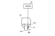
- FIG. It is a figure which shows the configuration example and the operation example of the teaching apparatus which concerns on Embodiment 2.
- FIG. It is a block which shows the structural example of the teaching apparatus which concerns on Embodiment 2.
- FIG. 1 is a diagram showing a configuration example and an operation example of the teaching device according to the first embodiment.
- the teaching device is a device for the user to directly teach the gripping force to the robot hand 101.
- This teaching device may have a function related to direct teaching of the opening degree in addition to the function related to the direct teaching of the gripping force, but the function related to the direct teaching of the opening degree is the same as the conventional one. Omit.
- this teaching device includes a torque sensor 11, a force calculation unit 12, and a force teaching unit 13.
- the torque sensor 11 is attached to the robot hand 101, and applies torque (a moment component around an axis (one axis or more)) due to a repulsive force in a direction opposite to the gripping direction applied to the tip of the finger 102 of the robot hand 101. It is a detection sensor that detects.
- the torque sensor 11 is attached to a joint portion or a root portion of the finger 102 in the robot hand 101.
- the force calculation unit 12 calculates the repulsive force applied to the tip of the finger 102 of the robot hand 101 from the torque detected by the torque sensor 11. At this time, the force calculation unit 12 subtracts the initial value (detected value when no force is applied to the robot hand 101) from the detected value of the torque sensor 11, and sets the difference value and the hand length to the mounting position. Based on this, the repulsive force applied to the tip of the finger 102 of the robot hand 101 is calculated.
- the force teaching unit 13 registers the gripping force taught to the robot hand 101 based on the repulsive force calculated by the force calculating unit 12. As shown in FIG. 2, the force teaching unit 13 includes a lock instruction receiving unit 14, a hand control unit 15, a notification unit 16, a force registration unit 17, and a recording unit 18.
- the force calculation unit 12 and the force teaching unit 13 are realized by a processing circuit such as a system LSI (Large Scale Integration), a CPU (Central Processing Unit) that executes a program stored in a memory or the like, or the like.
- a processing circuit such as a system LSI (Large Scale Integration), a CPU (Central Processing Unit) that executes a program stored in a memory or the like, or the like.
- the lock instruction receiving unit 14 receives the servo lock instruction from the user.
- the servo lock instruction is an instruction input to the teaching device when the user servo-locks the robot hand 101.
- the user inputs the servo lock instruction by using, for example, the operation button (not shown) of the robot hand 101 or the operation button of the teaching pendant (not shown).
- the hand control unit 15 servo-locks the robot hand 101 at the timing when the servo lock instruction is received by the lock instruction receiving unit 14.
- the notification unit 16 notifies the repulsive force calculated by the force calculation unit 12 in real time.
- the information indicating the repulsive force notified by the notification unit 16 is displayed on a display device (not shown).
- the notification unit 16 is not essential to the teaching device and may not be provided in the teaching device. For example, in the direct teaching of the gripping force, the notification unit 16 is unnecessary when the user does not need to teach while checking the repulsive force applied to the robot hand 101.
- the force registration unit 17 sets the value of the repulsive force calculated by the force calculation unit 12 and the reverse direction after the robot hand 101 is servo-locked by the hand control unit 15 as the value of the gripping force taught to the robot hand 101. And the direction is registered in the recording unit 18.
- the recording unit 18 is composed of an HDD (Hard Disk Drive), a DVD (Digital entirely Disk), a memory, or the like. Further, FIG. 2 shows a case where the recording unit 18 is provided inside the teaching device, but the present invention is not limited to this, and the recording unit 18 may be provided outside the teaching device.
- teaching device may perform the direct teaching of the gripping force separately from the direct teaching of the opening degree, or may be performed at the same time as the direct teaching of the opening degree.
- FIG. 1 a case where the robot hand 101 teaches the gripping force when gripping the object 201 is shown.
- the opening degree is easily visually grasped by the user and the opening degree can be easily reproduced.
- the gripping force is difficult for the user to visually grasp and it is difficult to reproduce the gripping force.
- the robot hand 101 is pressed against the object 201 to be in the servo-locked state (stationary state).
- the torque sensor 11 can detect the torque due to the repulsive force.
- the user first brings the finger 102 of the robot hand 101 into contact with the object 201 so as to sandwich it.
- the user manually applies a force to the finger 102 in the gripping direction or operates the finger 102 with the teaching pendant to press the finger 102 against the object 201 in the gripping direction.
- the pressing force applied to the finger 102 is canceled by the repulsive force from the object 201, so that the torque sensor 11 cannot detect the torque.
- the user inputs a servo lock instruction to the teaching device when it is determined from the repulsive force (pressing force) felt by the finger 102 from the finger 102 or the degree of deformation of the object 201 that the gripping state is optimal.
- the hand control unit 15 servo-locks the robot hand 101.
- the user releases the finger 102.
- the torque sensor 11 detects the torque due to this repulsive force, and the force calculation unit 12 calculates the repulsive force from this torque.
- the arrow indicated by reference numeral 501 indicates the repulsive force applied from the object 201.
- the notification unit 16 notifies the repulsive force calculated by the force calculation unit 12 in real time, and the display device displays information indicating the repulsive force.
- the user can confirm the repulsive force applied to the finger 102 and re-teach the pressing force applied to the finger 102. That is, the user may perform re-teaching by confirming the repulsive force after putting the robot hand 101 in the servo-locked state, returning the robot hand 101 to the servo-on state, and repeating the above operation again if necessary.
- the force registration unit 17 registers the repulsive force value and the reverse direction calculated by the force calculation unit 12 in the recording unit 18 as the gripping force value and direction taught to the robot hand 101.
- the user can teach the gripping force to the robot hand 101.
- the teaching device includes the torque sensor 11 that detects the torque due to the repulsive force applied to the tip of the finger 102 of the robot hand 101 in the direction opposite to the gripping direction.
- a force calculation unit 12 that calculates the repulsive force applied to the tip of the finger 102 of the robot hand 101 from the torque detected by the torque sensor 11, a lock instruction reception unit 14 that receives a servo lock instruction from the user, and a lock.
- the hand control unit 15 that servo-locks the robot hand 101 at the timing when the instruction receiving unit 14 receives the servo lock instruction, and the repulsion calculated by the force calculation unit 12 after the robot hand 101 is servo-locked by the hand control unit 15.
- a force registration unit 17 for registering the force value and the reverse direction as the gripping force value and direction taught to the robot hand 101 is provided. As a result, the teaching device according to the first embodiment can directly teach the gripping force to the robot hand 101.
- Embodiment 2 In the teaching device according to the first embodiment, a case where a torque sensor 11 applied to the robot hand 101 for detecting torque due to a repulsive force in a direction opposite to the gripping direction is used is shown. On the other hand, in the teaching device according to the second embodiment, the case where the force sensor 21 applied to the robot hand 101 for detecting the repulsive force in the direction opposite to the gripping direction is used is shown.
- FIG. 3 is a diagram showing a configuration example and an operation example of the teaching device according to the second embodiment.
- the teaching device is a device for the user to directly teach the gripping force to the robot hand 101.
- This teaching device may have a function related to direct teaching of the opening degree in addition to the function related to the direct teaching of the gripping force, but the function related to the direct teaching of the opening degree is the same as the conventional one. Omit.
- this teaching device includes a force sensor 21 and a force teaching unit 22.
- the force sensor 21 is a sensor that is attached to the robot hand 101 and detects a repulsive force applied to the tip of the finger 102 of the robot hand 101 in a direction opposite to the gripping direction.
- a force sensor or the like that detects a force component in a direction of one axis or more is used.
- the force sensor 21 is attached to the tip portion of the finger 102 included in the robot hand 101.
- the present invention is not limited to this, and the force sensor 21 may be attached to a position where the repulsive force applied to the tip of the finger 102 can be detected.
- the force teaching unit 22 registers the gripping force taught to the robot hand 101 based on the repulsive force detected by the force sensor 21.
- the force teaching unit 22 includes a notification unit 23, a lock instruction receiving unit 24, a hand control unit 25, a force registration unit 26, and a recording unit 27.
- the force teaching unit 22 is realized by a processing circuit such as a system LSI, or a CPU or the like that executes a program stored in a memory or the like.
- the notification unit 23 notifies the repulsive force detected by the force sensor 21 in real time.
- the information indicating the repulsive force notified by the notification unit 23 is displayed on the display device.
- the notification unit 23 is not essential to the teaching device and may not be provided in the teaching device. For example, in the direct teaching of the gripping force, the notification unit 23 is unnecessary when the user does not need to teach while checking the repulsive force applied to the robot hand 101.
- the lock instruction reception unit 24 receives the servo lock instruction from the user.
- the servo lock instruction is an instruction input to the teaching device when the user servo-locks the robot hand 101.
- the user inputs the servo lock instruction by using, for example, the operation button of the robot hand 101 or the operation button of the teaching pendant.
- the hand control unit 25 servo-locks the robot hand 101 at the timing when the servo lock instruction is received by the lock instruction receiving unit 24.
- the force registration unit 26 sets the repulsive force value and the reverse direction detected by the force sensor 21 after the robot hand 101 is servo-locked by the hand control unit 25 as the gripping force value and the gripping force value taught to the robot hand 101.
- the direction is registered in the recording unit 27.
- the recording unit 27 is composed of an HDD, a DVD, a memory, or the like. Further, FIG. 4 shows a case where the recording unit 27 is provided inside the teaching device, but the present invention is not limited to this, and the recording unit 27 may be provided outside the teaching device.
- FIG. 3 a case where the robot hand 101 teaches the gripping force when gripping the object 201 is shown.
- the opening degree is easily visually grasped by the user and the opening degree can be easily reproduced.
- the gripping force is difficult for the user to visually grasp and it is difficult to reproduce the gripping force.
- the user first brings the finger 102 of the robot hand 101 into contact with the object 201 so as to sandwich it.
- the user manually applies a force to the finger 102 in the gripping direction or operates the finger 102 with the teaching pendant to press the finger 102 against the object 201 in the gripping direction.
- the notification unit 23 notifies the repulsive force detected by the force sensor 21 in real time, and the display device displays information indicating the repulsive force.
- the user can also adjust the pressing force applied to the finger 102 while monitoring the repulsive force applied to the finger 102.
- the user inputs a servo lock instruction to the teaching device when it is determined from the repulsive force (pressing force) felt by the finger 102 from the finger 102 or the degree of deformation of the object 201 that the gripping state is optimal.
- the hand control unit 25 servo-locks the robot hand 101.
- the user releases the finger 102.
- the force sensor 21 detects this repulsive force.
- the arrow indicated by reference numeral 502 indicates the repulsive force applied from the object 201.
- the force registration unit 26 registers the value and the reverse direction of the repulsive force detected by the force sensor 21 in the recording unit 27 as the value and direction of the gripping force taught to the robot hand 101.
- the user can teach the gripping force to the robot hand 101.
- the teaching device includes the force sensor 21 that detects the repulsive force applied to the tip of the finger 102 of the robot hand 101 in the direction opposite to the gripping direction, and the user.
- the lock instruction receiving unit 24 that receives the servo lock instruction from the robot
- the hand control unit 25 that servo-locks the robot hand 101 at the timing when the servo lock instruction is received by the lock instruction receiving unit 24, and the robot hand 101 by the hand control unit 25.
- It is provided with a force registration unit 26 that registers the value and reverse direction of the repulsive force detected by the force sensor 21 after being servo-locked as the value and direction of the gripping force taught to the robot hand 101.
- the teaching device according to the second embodiment can directly teach the gripping force to the robot hand 101.
- the teaching device according to the present invention can directly teach the gripping force to the robot hand, and is suitable for use as a teaching device or the like for directly teaching the gripping force to the robot hand.
Landscapes
- Physics & Mathematics (AREA)
- General Physics & Mathematics (AREA)
- Engineering & Computer Science (AREA)
- Automation & Control Theory (AREA)
- Numerical Control (AREA)
- Manipulator (AREA)
Abstract
ロボットハンド(101)が有するフィンガ(102)の先端に加えられた、把持方向とは反対方向の反発力によるトルクを検出するトルクセンサ(11)と、トルクセンサ(11)により検出されたトルクから、ロボットハンド(101)が有するフィンガ(102)の先端に加えられた反発力を算出する力算出部(12)と、ユーザからサーボロック指示を受付けるロック指示受付部(14)と、ロック指示受付部(14)によりサーボロック指示を受付けたタイミングで、ロボットハンド(101)をサーボロックするハンド制御部(15)と、ハンド制御部(15)によりロボットハンド(101)がサーボロックされた後に力算出部(12)により算出された反発力の値及び逆方向を、ロボットハンド(101)に対して教示された把持力の値及び方向として登録する力登録部(17)とを備えた。
Description
この発明は、ロボットハンドに対して把持力をダイレクト教示するための教示装置及び教示方法に関する。
従来から、教示装置は、ユーザによるロボットアームに対する位置及び姿勢のダイレクト教示を可能としている(例えば特許文献1,2参照)。一方、従来の教示装置では、ロボットハンドに対する把持力の教示については、ユーザによる教示ペンダントを用いた数値入力に応じ、把持力の値及び方向を設定している。
上記のように、従来の教示装置では、ロボットハンドに対する把持力の教示については、ユーザによる教示ペンダントを用いた数値入力を受付けている。しかしながら、この場合、ユーザは、事前に実験を行って、入力する数値を確認する必要がある。そのため、ロボットハンドに対する把持力の教示は、作業工数という観点では煩わしく、改善が求められている。
この発明は、上記のような課題を解決するためになされたもので、ロボットハンドに対して把持力のダイレクト教示が可能な教示装置を提供することを目的としている。
この発明に係る教示装置は、ロボットハンドが有するフィンガの先端に加えられた、把持方向と反対方向の反発力によるトルクを検出するトルクセンサと、トルクセンサにより検出されたトルクから、ロボットハンドが有するフィンガの先端に加えられた反発力を算出する力算出部と、ユーザからサーボロック指示を受付けるロック指示受付部と、ロック指示受付部によりサーボロック指示を受付けたタイミングで、ロボットハンドをサーボロックするハンド制御部と、ハンド制御部によりロボットハンドがサーボロックされた後に力算出部により算出された反発力の値及び逆方向を、当該ロボットハンドに対して教示された把持力の値及び方向として登録する力登録部とを備えたことを特徴とする。
この発明によれば、上記のように構成したので、ロボットハンドに対して把持力のダイレクト教示が可能となる。
以下、この発明の実施の形態について図面を参照しながら詳細に説明する。
実施の形態1.
図1は実施の形態1に係る教示装置の構成例及び動作例を示す図である。
教示装置は、ユーザがロボットハンド101に対して把持力のダイレクト教示を実施するための装置である。この教示装置は、把持力のダイレクト教示に関する機能の他に、開度のダイレクト教示に関する機能も有していてもよいが、開度のダイレクト教示に関する機能については従来と同様であるためその説明を省略する。この教示装置は、図1に示すように、トルクセンサ11、力算出部12及び力教示部13を備えている。
実施の形態1.
図1は実施の形態1に係る教示装置の構成例及び動作例を示す図である。
教示装置は、ユーザがロボットハンド101に対して把持力のダイレクト教示を実施するための装置である。この教示装置は、把持力のダイレクト教示に関する機能の他に、開度のダイレクト教示に関する機能も有していてもよいが、開度のダイレクト教示に関する機能については従来と同様であるためその説明を省略する。この教示装置は、図1に示すように、トルクセンサ11、力算出部12及び力教示部13を備えている。
トルクセンサ11は、ロボットハンド101に取付けられ、ロボットハンド101が有するフィンガ102の先端に加えられた、把持方向とは反対方向の反発力によるトルク(軸(1軸以上)回りのモーメント成分)を検出する検出センサである。トルクセンサ11は、ロボットハンド101におけるフィンガ102の関節部分又は根元部分に取付けられている。
力算出部12は、トルクセンサ11により検出されたトルクから、ロボットハンド101が有するフィンガ102の先端に加えられた反発力を算出する。この際、力算出部12は、トルクセンサ11の検出値から初期値(ロボットハンド101に力が加えられていない状態での検出値)を差し引き、その差分値及び取付け位置までのハンド長さに基づいてロボットハンド101が有するフィンガ102の先端に加えられた反発力を算出する。
力教示部13は、力算出部12により算出された反発力に基づいて、ロボットハンド101に対して教示された把持力を登録する。この力教示部13は、図2に示すように、ロック指示受付部14、ハンド制御部15、通知部16、力登録部17及び記録部18を有している。
なお、力算出部12及び力教示部13は、システムLSI(Large Scale Integration)等の処理回路、又はメモリ等に記憶されたプログラムを実行するCPU(Central Processing Unit)等により実現される。
ロック指示受付部14は、ユーザからサーボロック指示を受付ける。サーボロック指示は、ユーザがロボットハンド101をサーボロックする際に教示装置に対して入力する指示である。なお、ユーザは、例えばロボットハンド101が有する操作ボタン(不図示)又は教示ペンダント(不図示)が有する操作ボタン等を用いて、サーボロック指示の入力を行う。
ハンド制御部15は、ロック指示受付部14によりサーボロック指示を受付けたタイミングで、ロボットハンド101をサーボロックする。
通知部16は、力算出部12により算出された反発力をリアルタイムに通知する。この通知部16により通知された反発力を示す情報は、表示装置(不図示)に表示される。
なお、通知部16は、教示装置に必須の構成ではなく、教示装置に設けられていなくてもよい。例えば、ユーザが、把持力のダイレクト教示において、ロボットハンド101に加えられている反発力を確認しながら教示を行う必要が無い場合には、通知部16は不要である。
なお、通知部16は、教示装置に必須の構成ではなく、教示装置に設けられていなくてもよい。例えば、ユーザが、把持力のダイレクト教示において、ロボットハンド101に加えられている反発力を確認しながら教示を行う必要が無い場合には、通知部16は不要である。
力登録部17は、ハンド制御部15によりロボットハンド101がサーボロックされた後に力算出部12により算出された反発力の値及び逆方向を、ロボットハンド101に対して教示された把持力の値及び方向として記録部18に登録する。
なお、記録部18は、HDD(Hard Disk Drive)、DVD(Digital Versatile Disc)又はメモリ等によって構成される。
また図2では、記録部18が教示装置の内部に設けられた場合を示しているが、これに限らず、記録部18は教示装置の外部に設けられていてもよい。
また図2では、記録部18が教示装置の内部に設けられた場合を示しているが、これに限らず、記録部18は教示装置の外部に設けられていてもよい。
また、教示装置は、把持力のダイレクト教示を、開度のダイレクト教示とは別に実施するものとしてもよいし、開度のダイレクト教示と同時に実施するものとしてもよい。
次に、図1,2に示す教示装置を用いた把持力のダイレクト教示の一例について説明する。以下では、図1に示すように、ロボットハンド101が物体201を把持する際の把持力を教示する場合を示す。
ここで、ユーザがロボットハンド101に対して開度をダイレクト教示する場合、開度はユーザにとって視覚的に捉え易く開度の再現は容易である。これに対し、ユーザがロボットハンド101に対して把持力をダイレクト教示しようとする場合には、把持力はユーザにとって視覚的に捉え難く把持力の再現は難しい。一方、ロボットハンド101が物体201を押すと、押付方向とは反対方向にこの押付力に応じた反発力がロボットハンド101に加えられる。そこで、実施の形態1に係る教示装置では、ロボットハンド101に加えられた反発力によるトルクを検出可能なトルクセンサ11を用いることで、把持力のダイレクト教示を実現する。
一方、ロボットハンド101を自由に動かせる状態でユーザがロボットハンド101を物体201に押付けると、この押付力が物体201からの反発力で相殺されてしまうため、トルクセンサ11はトルクを検出できない。そのため、この状態ではロボットハンド101に対する把持力のダイレクト教示は実施できない。そこで、実施の形態1に係る教示装置では、ユーザがロボットハンド101を物体201に押付けた状態でサーボロック状態(静止状態)とする。これにより、この状態でユーザがロボットハンド101から手を離すと、ロボットハンド101には反発力のみが加えられた状態となり、トルクセンサ11はこの反発力によるトルクを検出可能となる。
ここで、ユーザがロボットハンド101に対して開度をダイレクト教示する場合、開度はユーザにとって視覚的に捉え易く開度の再現は容易である。これに対し、ユーザがロボットハンド101に対して把持力をダイレクト教示しようとする場合には、把持力はユーザにとって視覚的に捉え難く把持力の再現は難しい。一方、ロボットハンド101が物体201を押すと、押付方向とは反対方向にこの押付力に応じた反発力がロボットハンド101に加えられる。そこで、実施の形態1に係る教示装置では、ロボットハンド101に加えられた反発力によるトルクを検出可能なトルクセンサ11を用いることで、把持力のダイレクト教示を実現する。
一方、ロボットハンド101を自由に動かせる状態でユーザがロボットハンド101を物体201に押付けると、この押付力が物体201からの反発力で相殺されてしまうため、トルクセンサ11はトルクを検出できない。そのため、この状態ではロボットハンド101に対する把持力のダイレクト教示は実施できない。そこで、実施の形態1に係る教示装置では、ユーザがロボットハンド101を物体201に押付けた状態でサーボロック状態(静止状態)とする。これにより、この状態でユーザがロボットハンド101から手を離すと、ロボットハンド101には反発力のみが加えられた状態となり、トルクセンサ11はこの反発力によるトルクを検出可能となる。
把持力のダイレクト教示では、ユーザは、まず、ロボットハンド101が有するフィンガ102を、物体201を挟み込ませるように当接させる。
次いで、ユーザは、フィンガ102に対して手で把持方向に力を加え又は教示ペンダントでフィンガ102を操作し、フィンガ102を物体201に把持方向に押付ける。なおこの状態では、フィンガ102に加えられた押付力は物体201からの反発力によって相殺されてしまうため、トルクセンサ11ではトルクを検出できない。
次いで、ユーザは、フィンガ102から自身の指に感じる反発力(押付力)又は物体201の変形具合から最適な把持状態と判断した場合に、サーボロック指示を教示装置に入力する。
次いで、ハンド制御部15は、ロボットハンド101をサーボロックする。
次いで、ハンド制御部15は、ロボットハンド101をサーボロックする。
次いで、ユーザは、フィンガ102から手を離す。これにより、フィンガ102には物体201からの反発力のみが加わる。そして、トルクセンサ11はこの反発力によるトルクを検出し、力算出部12はこのトルクから当該反発力を算出する。図1において、符号501に示す矢印は物体201から加えられた反発力を示している。
また、通知部16は力算出部12により算出された反発力をリアルタイムに通知し、表示装置はその反発力を示す情報を表示する。これにより、ユーザは、フィンガ102に加えられた反発力を確認してフィンガ102に加える押付力を再教示することもできる。すなわち、ユーザは、ロボットハンド101をサーボロック状態とした後に反発力を確認し、必要に応じてロボットハンド101をサーボオン状態に戻して再度上記の操作を繰返すことで再教示を行ってもよい。
次いで、力登録部17は、力算出部12により算出された反発力の値及び逆方向を、ロボットハンド101に対して教示された把持力の値及び方向として記録部18に登録する。
以上の動作により、ユーザは、ロボットハンド101に対して把持力を教示できる。
以上の動作により、ユーザは、ロボットハンド101に対して把持力を教示できる。
以上のように、この実施の形態1によれば、教示装置は、ロボットハンド101が有するフィンガ102の先端に加えられた、把持方向とは反対方向の反発力によるトルクを検出するトルクセンサ11と、トルクセンサ11により検出されたトルクから、ロボットハンド101が有するフィンガ102の先端に加えられた反発力を算出する力算出部12と、ユーザからサーボロック指示を受付けるロック指示受付部14と、ロック指示受付部14によりサーボロック指示を受付けたタイミングで、ロボットハンド101をサーボロックするハンド制御部15と、ハンド制御部15によりロボットハンド101がサーボロックされた後に力算出部12により算出された反発力の値及び逆方向を、ロボットハンド101に対して教示された把持力の値及び方向として登録する力登録部17とを備えた。これにより、実施の形態1に係る教示装置は、ロボットハンド101に対して把持力のダイレクト教示が可能となる。
実施の形態2.
実施の形態1に係る教示装置では、ロボットハンド101に加えられた、把持方向とは反対方向の反発力によるトルクを検出するトルクセンサ11を用いた場合を示した。それに対し、実施の形態2に係る教示装置では、ロボットハンド101に加えられた、把持方向とは反対方向の反発力を検出する力センサ21を用いた場合を示す。
実施の形態1に係る教示装置では、ロボットハンド101に加えられた、把持方向とは反対方向の反発力によるトルクを検出するトルクセンサ11を用いた場合を示した。それに対し、実施の形態2に係る教示装置では、ロボットハンド101に加えられた、把持方向とは反対方向の反発力を検出する力センサ21を用いた場合を示す。
図3は実施の形態2に係る教示装置の構成例及び動作例を示す図である。
教示装置は、ユーザがロボットハンド101に対して把持力のダイレクト教示を実施するための装置である。この教示装置は、把持力のダイレクト教示に関する機能の他に、開度のダイレクト教示に関する機能も有していてもよいが、開度のダイレクト教示に関する機能については従来と同様であるためその説明を省略する。この教示装置は、図3に示すように、力センサ21及び力教示部22を備えている。
教示装置は、ユーザがロボットハンド101に対して把持力のダイレクト教示を実施するための装置である。この教示装置は、把持力のダイレクト教示に関する機能の他に、開度のダイレクト教示に関する機能も有していてもよいが、開度のダイレクト教示に関する機能については従来と同様であるためその説明を省略する。この教示装置は、図3に示すように、力センサ21及び力教示部22を備えている。
力センサ21は、ロボットハンド101に取付けられ、ロボットハンド101が有するフィンガ102の先端に加えられた、把持方向とは反対方向の反発力を検出するセンサである。力センサ21としては、一軸以上の方向の力成分を検出する力センサ等が用いられる。
図3では、力センサ21は、ロボットハンド101が有するフィンガ102の先端部分に取付けられている。しかしながら、これに限らず、力センサ21は、フィンガ102の先端に加えられた反発力を検出可能な箇所に取付けられていればよい。
図3では、力センサ21は、ロボットハンド101が有するフィンガ102の先端部分に取付けられている。しかしながら、これに限らず、力センサ21は、フィンガ102の先端に加えられた反発力を検出可能な箇所に取付けられていればよい。
力教示部22は、力センサ21により検出された反発力に基づいて、ロボットハンド101に対して教示された把持力を登録する。この力教示部22は、図4に示すように、通知部23、ロック指示受付部24、ハンド制御部25、力登録部26及び記録部27を有している。なお、力教示部22は、システムLSI等の処理回路、又はメモリ等に記憶されたプログラムを実行するCPU等により実現される。
通知部23は、力センサ21により検出された反発力をリアルタイムに通知する。この通知部23により通知された反発力を示す情報は、表示装置に表示される。
なお、通知部23は、教示装置に必須の構成ではなく、教示装置に設けられていなくてもよい。例えば、ユーザが、把持力のダイレクト教示において、ロボットハンド101に加えられている反発力を確認しながら教示を行う必要が無い場合には、通知部23は不要である。
なお、通知部23は、教示装置に必須の構成ではなく、教示装置に設けられていなくてもよい。例えば、ユーザが、把持力のダイレクト教示において、ロボットハンド101に加えられている反発力を確認しながら教示を行う必要が無い場合には、通知部23は不要である。
ロック指示受付部24は、ユーザからサーボロック指示を受付ける。サーボロック指示は、ユーザがロボットハンド101をサーボロックする際に教示装置に対して入力する指示である。なお、ユーザは、例えばロボットハンド101が有する操作ボタン又は教示ペンダントが有する操作ボタン等を用いて、サーボロック指示の入力を行う。
ハンド制御部25は、ロック指示受付部24によりサーボロック指示を受付けたタイミングで、ロボットハンド101をサーボロックする。
力登録部26は、ハンド制御部25によりロボットハンド101がサーボロックされた後に力センサ21により検出された反発力の値及び逆方向を、ロボットハンド101に対して教示された把持力の値及び方向として記録部27に登録する。
なお、記録部27は、HDD、DVD又はメモリ等によって構成される。
また図4では、記録部27が教示装置の内部に設けられた場合を示しているが、これに限らず、記録部27は教示装置の外部に設けられていてもよい。
また図4では、記録部27が教示装置の内部に設けられた場合を示しているが、これに限らず、記録部27は教示装置の外部に設けられていてもよい。
次に、図3,4に示す教示装置を用いた把持力のダイレクト教示の一例について説明する。以下では、図3に示すように、ロボットハンド101が物体201を把持する際の把持力を教示する場合を示す。
ここで、ユーザがロボットハンド101に対して開度をダイレクト教示する場合、開度はユーザにとって視覚的に捉え易く開度の再現は容易である。これに対し、ユーザがロボットハンド101に対して把持力をダイレクト教示しようとする場合には、把持力はユーザにとって視覚的に捉え難く把持力の再現は難しい。一方、ロボットハンド101が物体201を押すと、押付方向とは反対方向にこの押付力に応じた反発力がロボットハンド101に加えられる。そこで、実施の形態2に係る教示装置では、ロボットハンド101に加えられた反発力を検出可能な力センサ21を用いることで、把持力のダイレクト教示を実現する。
ここで、ユーザがロボットハンド101に対して開度をダイレクト教示する場合、開度はユーザにとって視覚的に捉え易く開度の再現は容易である。これに対し、ユーザがロボットハンド101に対して把持力をダイレクト教示しようとする場合には、把持力はユーザにとって視覚的に捉え難く把持力の再現は難しい。一方、ロボットハンド101が物体201を押すと、押付方向とは反対方向にこの押付力に応じた反発力がロボットハンド101に加えられる。そこで、実施の形態2に係る教示装置では、ロボットハンド101に加えられた反発力を検出可能な力センサ21を用いることで、把持力のダイレクト教示を実現する。
把持力のダイレクト教示では、ユーザは、まず、ロボットハンド101が有するフィンガ102を、物体201を挟み込ませるように当接させる。
次いで、ユーザは、フィンガ102に対して手で把持方向に力を加え又は教示ペンダントでフィンガ102を操作し、フィンガ102を物体201に把持方向に押付ける。
また、通知部23は力センサ21により検出された反発力をリアルタイムに通知し、表示装置はその反発力を示す情報を表示する。これにより、ユーザは、フィンガ102に加えられた反発力をモニタしながらフィンガ102に加える押付力を調整することもできる。
次いで、ユーザは、フィンガ102から自身の指に感じる反発力(押付力)又は物体201の変形具合から最適な把持状態と判断した場合に、サーボロック指示を教示装置に入力する。
次いで、ハンド制御部25は、ロボットハンド101をサーボロックする。
次いで、ハンド制御部25は、ロボットハンド101をサーボロックする。
次いで、ユーザは、フィンガ102から手を離す。これにより、フィンガ102には物体201からの反発力のみが加わる。そして、力センサ21はこの反発力を検出する。図3において、符号502に示す矢印は物体201から加えられた反発力を示している。
次いで、力登録部26は、力センサ21により検出された反発力の値及び逆方向を、ロボットハンド101に対して教示された把持力の値及び方向として記録部27に登録する。
以上の動作により、ユーザは、ロボットハンド101に対して把持力を教示できる。
以上の動作により、ユーザは、ロボットハンド101に対して把持力を教示できる。
以上のように、この実施の形態2によれば、教示装置は、ロボットハンド101が有するフィンガ102の先端に加えられた、把持方向とは反対方向の反発力を検出する力センサ21と、ユーザからサーボロック指示を受付けるロック指示受付部24と、ロック指示受付部24によりサーボロック指示を受付けたタイミングで、ロボットハンド101をサーボロックするハンド制御部25と、ハンド制御部25によりロボットハンド101がサーボロックされた後に力センサ21により検出された反発力の値及び逆方向を、ロボットハンド101に対して教示された把持力の値及び方向として登録する力登録部26とを備えた。これにより、実施の形態2に係る教示装置は、ロボットハンド101に対して把持力のダイレクト教示が可能となる。
なお、本願発明はその発明の範囲内において、各実施の形態の自由な組合わせ、或いは各実施の形態の任意の構成要素の変形、若しくは各実施の形態において任意の構成要素の省略が可能である。
この発明に係る教示装置は、ロボットハンドに対して把持力のダイレクト教示が可能となり、ロボットハンドに対して把持力をダイレクト教示するための教示装置等に用いるのに適している。
11 トルクセンサ
12 力算出部
13 力教示部
14 ロック指示受付部
15 ハンド制御部
16 通知部
17 力登録部
18 記録部
21 力センサ
22 力教示部
23 通知部
24 ロック指示受付部
25 ハンド制御部
26 力登録部
27 記録部
101 ロボットハンド
102 フィンガ
12 力算出部
13 力教示部
14 ロック指示受付部
15 ハンド制御部
16 通知部
17 力登録部
18 記録部
21 力センサ
22 力教示部
23 通知部
24 ロック指示受付部
25 ハンド制御部
26 力登録部
27 記録部
101 ロボットハンド
102 フィンガ
Claims (7)
- ロボットハンドが有するフィンガの先端に加えられた、把持方向と反対方向の反発力によるトルクを検出するトルクセンサと、
前記トルクセンサにより検出されたトルクから、前記ロボットハンドが有するフィンガの先端に加えられた反発力を算出する力算出部と、
ユーザからサーボロック指示を受付けるロック指示受付部と、
前記ロック指示受付部によりサーボロック指示を受付けたタイミングで、前記ロボットハンドをサーボロックするハンド制御部と、
前記ハンド制御部により前記ロボットハンドがサーボロックされた後に前記力算出部により算出された反発力の値及び逆方向を、当該ロボットハンドに対して教示された把持力の値及び方向として登録する力登録部と
を備えた教示装置。 - 前記力算出部により算出された反発力をリアルタイムに通知する通知部を備えた
ことを特徴とする請求項1記載の教示装置。 - 前記力算出部は、前記トルクセンサの検出値から初期値を差し引いた差分値及び取付け位置までのハンド長さに基づいて、前記ロボットハンドに加えられた反発力を算出する
ことを特徴とする請求項1又は請求項2記載の教示装置。 - ロボットハンドが有するフィンガの先端に加えられた、把持方向とは反対方向の反発力を検出する力センサと、
ユーザからサーボロック指示を受付けるロック指示受付部と、
前記ロック指示受付部によりサーボロック指示を受付けたタイミングで、前記ロボットハンドをサーボロックするハンド制御部と、
前記ハンド制御部により前記ロボットハンドがサーボロックされた後に前記力センサにより検出された反発力の値及び逆方向を、前記ロボットハンドに対して教示された把持力の値及び方向として登録する力登録部と
を備えた教示装置。 - 前記力センサにより検出された反発力をリアルタイムに通知する通知部を備えた
ことを特徴とする請求項4記載の教示装置。 - ロボットハンドが有するフィンガの先端に加えられた、把持方向とは反対方向の反発力によるトルクを検出するトルクセンサを備えた教示装置による教示方法であって、
前記トルクセンサにより検出されたトルクから、前記ロボットハンドが有するフィンガの先端に加えられた反発力を算出する力算出ステップと、
ユーザからサーボロック指示を受付けるロック指示受付ステップと、
前記ロック指示受付ステップにおいてサーボロック指示を受付けたタイミングで、前記ロボットハンドをサーボロックするハンド制御ステップと、
前記ハンド制御ステップにおいて前記ロボットハンドをサーボロックした後に前記力算出ステップにおいて算出した反発力の値及び逆方向を、当該ロボットハンドに対して教示された把持力の値及び方向として登録する力登録ステップとを有する
ことを特徴とする教示方法。 - ロボットハンドが有するフィンガの先端に加えられた、把持方向とは反対方向の反発力を検出する力センサを備えた教示装置による教示方法であって、
ユーザからサーボロック指示を受付けるロック指示受付ステップと、
前記ロック指示受付ステップにおいてサーボロック指示を受付けたタイミングで、前記ロボットハンドをサーボロックするハンド制御ステップと、
前記ハンド制御ステップにおいて前記ロボットハンドをサーボロックした後に前記力センサにより検出された反発力の値及び逆方向を、前記ロボットハンドに対して教示された把持力の値及び方向として登録する力登録ステップとを有する
ことを特徴とする教示方法。
Applications Claiming Priority (2)
| Application Number | Priority Date | Filing Date | Title |
|---|---|---|---|
| JP2019118869A JP2021003767A (ja) | 2019-06-26 | 2019-06-26 | 教示装置及び教示方法 |
| JP2019-118869 | 2019-06-26 |
Publications (1)
| Publication Number | Publication Date |
|---|---|
| WO2020262170A1 true WO2020262170A1 (ja) | 2020-12-30 |
Family
ID=74060904
Family Applications (1)
| Application Number | Title | Priority Date | Filing Date |
|---|---|---|---|
| PCT/JP2020/023812 Ceased WO2020262170A1 (ja) | 2019-06-26 | 2020-06-17 | 教示装置及び教示方法 |
Country Status (2)
| Country | Link |
|---|---|
| JP (1) | JP2021003767A (ja) |
| WO (1) | WO2020262170A1 (ja) |
Cited By (1)
| Publication number | Priority date | Publication date | Assignee | Title |
|---|---|---|---|---|
| CN119328770A (zh) * | 2024-12-18 | 2025-01-21 | 成都思越智能装备股份有限公司 | 一种物料方向自适应夹持分析方法及装置 |
Citations (7)
| Publication number | Priority date | Publication date | Assignee | Title |
|---|---|---|---|---|
| JPH11231925A (ja) * | 1998-02-10 | 1999-08-27 | Yaskawa Electric Corp | ダイレクトティーチング用ロボットの手先 |
| JP2010058202A (ja) * | 2008-09-02 | 2010-03-18 | Yaskawa Electric Corp | ロボットの教示再生装置および教示再生方法 |
| JP2010076012A (ja) * | 2008-09-24 | 2010-04-08 | Toshiba Corp | マニピュレータシステムおよびその制御方法 |
| JP2016047591A (ja) * | 2014-08-27 | 2016-04-07 | キヤノン株式会社 | ロボット教示装置、方法、およびロボットシステム |
| WO2017036520A1 (en) * | 2015-09-02 | 2017-03-09 | Abb Schweiz Ag | System and method for generating a robot program with a hand-held teaching device |
| JP2018069385A (ja) * | 2016-10-31 | 2018-05-10 | セイコーエプソン株式会社 | ハンドおよびロボット |
| US10166676B1 (en) * | 2016-06-08 | 2019-01-01 | X Development Llc | Kinesthetic teaching of grasp parameters for grasping of objects by a grasping end effector of a robot |
-
2019
- 2019-06-26 JP JP2019118869A patent/JP2021003767A/ja active Pending
-
2020
- 2020-06-17 WO PCT/JP2020/023812 patent/WO2020262170A1/ja not_active Ceased
Patent Citations (7)
| Publication number | Priority date | Publication date | Assignee | Title |
|---|---|---|---|---|
| JPH11231925A (ja) * | 1998-02-10 | 1999-08-27 | Yaskawa Electric Corp | ダイレクトティーチング用ロボットの手先 |
| JP2010058202A (ja) * | 2008-09-02 | 2010-03-18 | Yaskawa Electric Corp | ロボットの教示再生装置および教示再生方法 |
| JP2010076012A (ja) * | 2008-09-24 | 2010-04-08 | Toshiba Corp | マニピュレータシステムおよびその制御方法 |
| JP2016047591A (ja) * | 2014-08-27 | 2016-04-07 | キヤノン株式会社 | ロボット教示装置、方法、およびロボットシステム |
| WO2017036520A1 (en) * | 2015-09-02 | 2017-03-09 | Abb Schweiz Ag | System and method for generating a robot program with a hand-held teaching device |
| US10166676B1 (en) * | 2016-06-08 | 2019-01-01 | X Development Llc | Kinesthetic teaching of grasp parameters for grasping of objects by a grasping end effector of a robot |
| JP2018069385A (ja) * | 2016-10-31 | 2018-05-10 | セイコーエプソン株式会社 | ハンドおよびロボット |
Cited By (1)
| Publication number | Priority date | Publication date | Assignee | Title |
|---|---|---|---|---|
| CN119328770A (zh) * | 2024-12-18 | 2025-01-21 | 成都思越智能装备股份有限公司 | 一种物料方向自适应夹持分析方法及装置 |
Also Published As
| Publication number | Publication date |
|---|---|
| JP2021003767A (ja) | 2021-01-14 |
Similar Documents
| Publication | Publication Date | Title |
|---|---|---|
| US20210114221A1 (en) | Method of teaching robot and robot system | |
| JP4643619B2 (ja) | ロボット制御装置 | |
| US9902059B2 (en) | Robot teaching apparatus, method, and robot system | |
| US10195744B2 (en) | Control device, robot, and robot system | |
| JP2015030086A (ja) | ロボット制御方法、ロボットシステム、プログラム及び記録媒体 | |
| US9144905B1 (en) | Device and method to identify functional parts of tools for robotic manipulation | |
| JP6852450B2 (ja) | 表示方法およびロボットシステム | |
| JP2015071207A (ja) | ロボットハンドおよびその制御方法 | |
| JP5593899B2 (ja) | ロボットによるバリ除去方法 | |
| JP2021003767A (ja) | 教示装置及び教示方法 | |
| JP6307838B2 (ja) | ロボット、ロボットシステムおよび制御装置 | |
| WO2020262168A1 (ja) | 教示装置及び教示方法 | |
| JP6679446B2 (ja) | 作業ロボットの遠隔操作システム | |
| WO2020262169A1 (ja) | 教示装置及び教示方法 | |
| JP6488571B2 (ja) | 教示装置、及びロボットシステム | |
| US20240131699A1 (en) | Robot system, learning apparatus, information processing apparatus, learned model, control method, information processing method, method for manufacturing product, and recording medium | |
| US12064885B2 (en) | Robot hand controller | |
| JP7273522B2 (ja) | 教示装置及び教示方法 | |
| JP2019089166A (ja) | 力検出システムおよびロボット | |
| JP2020116702A (ja) | 教示装置及び教示方法 | |
| JP2004160614A (ja) | 自動作業教示システム | |
| US20230264353A1 (en) | Manipulation apparatus, robot system, manipulation apparatus control method, and robot system control method | |
| JP2709001B2 (ja) | 力制御ロボットにおける作業対象物の位置検出装置 | |
| JP2014054692A (ja) | 状態判別方法、ロボット、制御装置、及びプログラム | |
| WO2021199931A1 (ja) | 教示装置 |
Legal Events
| Date | Code | Title | Description |
|---|---|---|---|
| 121 | Ep: the epo has been informed by wipo that ep was designated in this application |
Ref document number: 20830585 Country of ref document: EP Kind code of ref document: A1 |
|
| NENP | Non-entry into the national phase |
Ref country code: DE |
|
| 122 | Ep: pct application non-entry in european phase |
Ref document number: 20830585 Country of ref document: EP Kind code of ref document: A1 |