WO2020262094A1 - 車両用内装材及び車両用内装材の製造方法 - Google Patents
車両用内装材及び車両用内装材の製造方法 Download PDFInfo
- Publication number
- WO2020262094A1 WO2020262094A1 PCT/JP2020/023513 JP2020023513W WO2020262094A1 WO 2020262094 A1 WO2020262094 A1 WO 2020262094A1 JP 2020023513 W JP2020023513 W JP 2020023513W WO 2020262094 A1 WO2020262094 A1 WO 2020262094A1
- Authority
- WO
- WIPO (PCT)
- Prior art keywords
- vehicle interior
- interior material
- groove
- vehicle
- light receiving
- Prior art date
Links
- 238000004519 manufacturing process Methods 0.000 title claims description 6
- 239000000463 material Substances 0.000 claims description 60
- 238000001746 injection moulding Methods 0.000 claims description 10
- 238000000034 method Methods 0.000 claims description 5
- 230000004313 glare Effects 0.000 abstract description 13
- 238000002310 reflectometry Methods 0.000 abstract 1
- 238000012795 verification Methods 0.000 description 12
- 230000002238 attenuated effect Effects 0.000 description 5
- 230000000052 comparative effect Effects 0.000 description 4
- 239000011521 glass Substances 0.000 description 3
- 238000005259 measurement Methods 0.000 description 2
- NLHHRLWOUZZQLW-UHFFFAOYSA-N Acrylonitrile Chemical compound C=CC#N NLHHRLWOUZZQLW-UHFFFAOYSA-N 0.000 description 1
- 239000004743 Polypropylene Substances 0.000 description 1
- BZHJMEDXRYGGRV-UHFFFAOYSA-N Vinyl chloride Chemical compound ClC=C BZHJMEDXRYGGRV-UHFFFAOYSA-N 0.000 description 1
- NIXOWILDQLNWCW-UHFFFAOYSA-N acrylic acid group Chemical group C(C=C)(=O)O NIXOWILDQLNWCW-UHFFFAOYSA-N 0.000 description 1
- 230000000694 effects Effects 0.000 description 1
- 230000004438 eyesight Effects 0.000 description 1
- 238000000465 moulding Methods 0.000 description 1
- 230000002093 peripheral effect Effects 0.000 description 1
- 229920000515 polycarbonate Polymers 0.000 description 1
- 239000004417 polycarbonate Substances 0.000 description 1
- 229920000728 polyester Polymers 0.000 description 1
- -1 polypropylene Polymers 0.000 description 1
- 229920001155 polypropylene Polymers 0.000 description 1
- 239000011347 resin Substances 0.000 description 1
- 229920005989 resin Polymers 0.000 description 1
- 230000016776 visual perception Effects 0.000 description 1
Images


Classifications
-
- B—PERFORMING OPERATIONS; TRANSPORTING
- B60—VEHICLES IN GENERAL
- B60R—VEHICLES, VEHICLE FITTINGS, OR VEHICLE PARTS, NOT OTHERWISE PROVIDED FOR
- B60R13/00—Elements for body-finishing, identifying, or decorating; Arrangements or adaptations for advertising purposes
- B60R13/02—Internal Trim mouldings ; Internal Ledges; Wall liners for passenger compartments; Roof liners
- B60R13/0256—Dashboard liners
-
- B—PERFORMING OPERATIONS; TRANSPORTING
- B60—VEHICLES IN GENERAL
- B60R—VEHICLES, VEHICLE FITTINGS, OR VEHICLE PARTS, NOT OTHERWISE PROVIDED FOR
- B60R13/00—Elements for body-finishing, identifying, or decorating; Arrangements or adaptations for advertising purposes
- B60R13/02—Internal Trim mouldings ; Internal Ledges; Wall liners for passenger compartments; Roof liners
-
- B—PERFORMING OPERATIONS; TRANSPORTING
- B29—WORKING OF PLASTICS; WORKING OF SUBSTANCES IN A PLASTIC STATE IN GENERAL
- B29C—SHAPING OR JOINING OF PLASTICS; SHAPING OF MATERIAL IN A PLASTIC STATE, NOT OTHERWISE PROVIDED FOR; AFTER-TREATMENT OF THE SHAPED PRODUCTS, e.g. REPAIRING
- B29C45/00—Injection moulding, i.e. forcing the required volume of moulding material through a nozzle into a closed mould; Apparatus therefor
- B29C45/17—Component parts, details or accessories; Auxiliary operations
- B29C45/26—Moulds
- B29C45/37—Mould cavity walls, i.e. the inner surface forming the mould cavity, e.g. linings
- B29C45/372—Mould cavity walls, i.e. the inner surface forming the mould cavity, e.g. linings provided with means for marking or patterning, e.g. numbering articles
-
- B—PERFORMING OPERATIONS; TRANSPORTING
- B60—VEHICLES IN GENERAL
- B60K—ARRANGEMENT OR MOUNTING OF PROPULSION UNITS OR OF TRANSMISSIONS IN VEHICLES; ARRANGEMENT OR MOUNTING OF PLURAL DIVERSE PRIME-MOVERS IN VEHICLES; AUXILIARY DRIVES FOR VEHICLES; INSTRUMENTATION OR DASHBOARDS FOR VEHICLES; ARRANGEMENTS IN CONNECTION WITH COOLING, AIR INTAKE, GAS EXHAUST OR FUEL SUPPLY OF PROPULSION UNITS IN VEHICLES
- B60K35/00—Instruments specially adapted for vehicles; Arrangement of instruments in or on vehicles
- B60K35/40—Instruments specially adapted for improving the visibility thereof to the user, e.g. fogging prevention or anti-reflection arrangements
- B60K35/415—Glare prevention
-
- B—PERFORMING OPERATIONS; TRANSPORTING
- B60—VEHICLES IN GENERAL
- B60K—ARRANGEMENT OR MOUNTING OF PROPULSION UNITS OR OF TRANSMISSIONS IN VEHICLES; ARRANGEMENT OR MOUNTING OF PLURAL DIVERSE PRIME-MOVERS IN VEHICLES; AUXILIARY DRIVES FOR VEHICLES; INSTRUMENTATION OR DASHBOARDS FOR VEHICLES; ARRANGEMENTS IN CONNECTION WITH COOLING, AIR INTAKE, GAS EXHAUST OR FUEL SUPPLY OF PROPULSION UNITS IN VEHICLES
- B60K35/00—Instruments specially adapted for vehicles; Arrangement of instruments in or on vehicles
- B60K35/40—Instruments specially adapted for improving the visibility thereof to the user, e.g. fogging prevention or anti-reflection arrangements
- B60K35/425—Anti-reflection arrangements
-
- B—PERFORMING OPERATIONS; TRANSPORTING
- B60—VEHICLES IN GENERAL
- B60K—ARRANGEMENT OR MOUNTING OF PROPULSION UNITS OR OF TRANSMISSIONS IN VEHICLES; ARRANGEMENT OR MOUNTING OF PLURAL DIVERSE PRIME-MOVERS IN VEHICLES; AUXILIARY DRIVES FOR VEHICLES; INSTRUMENTATION OR DASHBOARDS FOR VEHICLES; ARRANGEMENTS IN CONNECTION WITH COOLING, AIR INTAKE, GAS EXHAUST OR FUEL SUPPLY OF PROPULSION UNITS IN VEHICLES
- B60K37/00—Dashboards
- B60K37/20—Dashboard panels
-
- G—PHYSICS
- G02—OPTICS
- G02B—OPTICAL ELEMENTS, SYSTEMS OR APPARATUS
- G02B5/00—Optical elements other than lenses
- G02B5/02—Diffusing elements; Afocal elements
- G02B5/0205—Diffusing elements; Afocal elements characterised by the diffusing properties
- G02B5/021—Diffusing elements; Afocal elements characterised by the diffusing properties the diffusion taking place at the element's surface, e.g. by means of surface roughening or microprismatic structures
- G02B5/0231—Diffusing elements; Afocal elements characterised by the diffusing properties the diffusion taking place at the element's surface, e.g. by means of surface roughening or microprismatic structures the surface having microprismatic or micropyramidal shape
-
- G—PHYSICS
- G02—OPTICS
- G02B—OPTICAL ELEMENTS, SYSTEMS OR APPARATUS
- G02B5/00—Optical elements other than lenses
- G02B5/04—Prisms
- G02B5/045—Prism arrays
-
- B—PERFORMING OPERATIONS; TRANSPORTING
- B29—WORKING OF PLASTICS; WORKING OF SUBSTANCES IN A PLASTIC STATE IN GENERAL
- B29K—INDEXING SCHEME ASSOCIATED WITH SUBCLASSES B29B, B29C OR B29D, RELATING TO MOULDING MATERIALS OR TO MATERIALS FOR MOULDS, REINFORCEMENTS, FILLERS OR PREFORMED PARTS, e.g. INSERTS
- B29K2995/00—Properties of moulding materials, reinforcements, fillers, preformed parts or moulds
- B29K2995/0037—Other properties
- B29K2995/0094—Geometrical properties
-
- B—PERFORMING OPERATIONS; TRANSPORTING
- B29—WORKING OF PLASTICS; WORKING OF SUBSTANCES IN A PLASTIC STATE IN GENERAL
- B29L—INDEXING SCHEME ASSOCIATED WITH SUBCLASS B29C, RELATING TO PARTICULAR ARTICLES
- B29L2031/00—Other particular articles
- B29L2031/30—Vehicles, e.g. ships or aircraft, or body parts thereof
- B29L2031/3005—Body finishings
- B29L2031/3008—Instrument panels
-
- B—PERFORMING OPERATIONS; TRANSPORTING
- B29—WORKING OF PLASTICS; WORKING OF SUBSTANCES IN A PLASTIC STATE IN GENERAL
- B29L—INDEXING SCHEME ASSOCIATED WITH SUBCLASS B29C, RELATING TO PARTICULAR ARTICLES
- B29L2031/00—Other particular articles
- B29L2031/30—Vehicles, e.g. ships or aircraft, or body parts thereof
- B29L2031/3005—Body finishings
- B29L2031/3014—Door linings
-
- B—PERFORMING OPERATIONS; TRANSPORTING
- B60—VEHICLES IN GENERAL
- B60K—ARRANGEMENT OR MOUNTING OF PROPULSION UNITS OR OF TRANSMISSIONS IN VEHICLES; ARRANGEMENT OR MOUNTING OF PLURAL DIVERSE PRIME-MOVERS IN VEHICLES; AUXILIARY DRIVES FOR VEHICLES; INSTRUMENTATION OR DASHBOARDS FOR VEHICLES; ARRANGEMENTS IN CONNECTION WITH COOLING, AIR INTAKE, GAS EXHAUST OR FUEL SUPPLY OF PROPULSION UNITS IN VEHICLES
- B60K2360/00—Indexing scheme associated with groups B60K35/00 or B60K37/00 relating to details of instruments or dashboards
- B60K2360/92—Manufacturing of instruments
Definitions
- the present invention relates to a vehicle interior material used for the interior of a vehicle and a method for manufacturing the vehicle interior material.
- an automobile is provided with a windshield, a sunroof glass, a door glass, etc., and the light is collected through these glasses.
- Light is essential for vision, but it also causes glare.
- the reflective skin material described in Patent Document 1 below is applied to an instrument panel or the like to absorb sunlight and reduce glare of passengers. More specifically, the reflective skin material has innumerable concave cross-sectional shapes including a light-reflecting surface and a light-absorbing surface, and absorbs the light reflected by the light-reflecting surface on the light-absorbing surface.
- an object of the present invention is to provide a vehicle interior material and a method for manufacturing a vehicle interior material, which can suppress the reflection of light to the outside and reduce glare from any angle of the passenger.
- the vehicle interior material according to the present invention has two flat reflecting surfaces having cross sections facing each other on the light receiving surface of the irradiated portion illuminated by the light from the outside in the interior of the vehicle. It is characterized in that it has a formed groove portion and the plane angle of the reflecting surface is 65 degrees or less.
- the vehicle interior material according to the present invention is characterized in that it is parallel to the light receiving surface and the angle of each reflecting surface with respect to the surface passing through the intersection of the reflecting surfaces is different.
- the opening of the groove and the intersection of the reflecting surfaces are arranged on the perpendicular of the light receiving surface, and the reflecting surfaces are oriented in opposite directions to the perpendicular. It is characterized by being inclined.
- At least one of the reflecting surfaces extends from the shallow surface portion in the depth direction of the groove portion to a shallow surface portion which is closer to the light receiving surface in the depth direction of the groove portion. It has a deep surface portion, and the plane angle of the deep surface portion is smaller than that of the shallow surface portion.
- the vehicle interior material according to the present invention is characterized in that the reflectance on the light receiving surface is 2.0% or less.
- the vehicle interior material according to the present invention is characterized in that the plane angle is 32 to 65 degrees.
- the reflecting surface is directed in a direction that intersects the overall length direction of the vehicle, and the light receiving surface is Among them, the inner side surface portion of the vehicle is characterized in that the reflective surface is directed in a direction intersecting the overall length direction of the vehicle.
- the method for manufacturing a vehicle interior material according to the present invention is characterized in that the depth direction of the groove portion in the vehicle interior material described above is directed to the direction in which the mold opens and closes in injection molding.
- the vehicle interior material according to the present invention has a groove portion formed by two flat reflecting surfaces whose cross sections face each other on the light receiving surface of the irradiated portion illuminated by the light from the outside in the interior of the vehicle.
- the plane angle of the reflecting surface is 65 degrees or less. That is, when the angle of the plane angle in the groove is 65 degrees or less, the light from the outside reflected by the reflecting surface of the groove travels in the depth direction of the groove while repeating the reflection, is attenuated, and is absorbed. Therefore, it is possible to suppress the reflection of light to the outside and reduce the glare felt by the occupant from any angle.
- the vehicle interior material according to the present invention is parallel to the light receiving surface, and the angle of each reflecting surface with respect to the surface passing through the intersection of the reflecting surfaces is different. With this configuration, light from the outside is attenuated and absorbed regardless of the direction of incidence. Therefore, it is possible to suppress the reflection of light to the outside and reduce the glare felt by the occupant from any angle.
- the opening of the groove and the intersection of the reflecting surfaces are arranged on the perpendicular line of the light receiving surface, and the reflecting surfaces are inclined in opposite directions with respect to the perpendicular line.
- the mold when the mold is opened, a portion of the mold corresponding to the intersection of the grooves is pulled out from the intersection to the opening through a vertical line. That is, injection molding can be performed by pulling out the mold straight. If the reflecting surface is inclined in the same direction with respect to the perpendicular line of the light receiving surface (when the groove portion is inclined with respect to the perpendicular line), the mold cannot be pulled out straight.
- the vehicle interior material according to the present invention has a shallow surface portion in which at least one reflecting surface is closer to the light receiving surface in the depth direction of the groove portion, and a deep surface portion extending from the shallow surface portion in the depth direction of the groove portion.
- the plane angle of the deep surface portion is smaller than that of the shallow surface portion.
- the vehicle interior material according to the present invention has a reflectance of 2.0% or less on the light receiving surface. Therefore, the glare felt by the passenger can be reduced.
- the vehicle interior material according to the present invention has a plane angle of 32 to 65 degrees. That is, when the angle of the plane angle in the groove is 32 to 65 degrees, it is possible to suppress the reflection of light to the outside and reduce the glare felt by the occupant from any angle.
- the reflecting surface in the upper surface portion of the light receiving surface facing upward in the vehicle, is directed in the direction intersecting the overall length direction of the vehicle, and the inside of the light receiving surface in the vehicle.
- the reflective surface is directed in a direction intersecting the overall length direction of the vehicle. That is, the glare felt by the passenger can be reduced regardless of the direction in which the reflective surface is directed.
- the method for manufacturing a vehicle interior material according to the present invention is such that the depth direction of the groove portion in the vehicle interior material described above is directed to the direction in which the mold opens and closes in injection molding. Therefore, vehicle interior materials can be easily manufactured by injection molding using a mold.
- FIG. 1 is a schematic view of the interior of an automobile to which the interior material for a vehicle according to the embodiment of the present invention is applied.
- FIG. 2 is a cross section of II-II in FIG. 1, which is an enlarged cross-sectional view of an interior material for a vehicle according to an embodiment of the present invention.
- FIG. 3 is a cross section of II-II in FIG. 1, which is an enlarged cross-sectional view of an interior material for a vehicle according to an embodiment of the present invention.
- FIG. 4 is a schematic view of the interior of an automobile provided with vehicle interior materials according to another embodiment of the present invention.
- FIG. 1 shows an outline of the interior of an automobile 1 to which the interior material 4 for a vehicle is applied.
- 2 and 3 show a cross section of the vehicle interior material 4.
- the groove portion 6 of the vehicle interior material 4 is exaggerated in order to make it easier to understand the present embodiment.
- the vehicle interior material 4 is applied to the surface of the instrument panel 2 and the door trim 3 as an irradiated portion illuminated by external light such as the sun and a street light in the interior of the automobile 1.
- the irradiated portion includes, for example, a combination meter peripheral area, a console, a pillar cover, a rear parcel shelf, an automobile camera cover (not shown), and the like.
- innumerable grooves 6 are formed on the light receiving surface 5 which is the surface, and the surface is zigzag.
- the cross section of the single groove 6 is substantially V-shaped and is composed of two flat reflecting surfaces facing each other.
- one reflecting surface is the first reflecting surface 7
- the other reflecting surface is the second reflecting surface 8
- the distance between the reflecting surfaces 7 and 8 is the groove width W
- the plane angle of each reflecting surface 7 and 8 is parallel to the groove angle ⁇ and the light receiving surface 5, and the first reflection on the parallel surface P which is a virtual surface passing through the intersection 10 of each reflecting surface 7 and 8.
- the angle of the surface 7 is the first outer angle ⁇
- the angle of the second reflecting surface 8 with respect to the parallel surface P is the second outer angle ⁇
- the direction in which the groove portion 6 is continuous is the groove length L (see FIG. 1).
- the opening 9 and the intersection 10 of the reflecting surfaces 7 and 8 are arranged on the perpendicular line V, and the reflecting surfaces 7 and 8 are inclined in opposite directions with respect to the perpendicular line V. ..
- the first reflecting surface 7 is a flat shallow surface portion 11 that is refracted and is closer to the light receiving surface 5 in the depth direction of the groove portion 6, and a flat deep surface portion 12 extending from the shallow surface portion 11 in the depth direction. And have.
- the plane angle of each of the reflecting surfaces 7 and 8 is smaller in the deep surface portion 12 than in the shallow surface portion 11 ( ⁇ > ⁇ 1 ).
- Such groove portions 6 are innumerably adjacent to each other in the groove width W direction.
- the number of refractions is arbitrary. Therefore, for example, if the number of refractions is two, the first reflecting surface portion 7 is composed of three surface portions, and if the number of refractions is three, the first reflecting surface portion 7 is composed of four surface portions. Will be done. In this case, as for each of the connected surface portions, the one arranged on the relatively shallow side is the shallow surface portion 11, and the one arranged on the relatively deep side is the deep surface portion 12.
- the first reflecting surface 7 and the second reflecting surface 8 may be single or multiple refracted, and only the second reflecting surface 8 may be single or multiple refracted. Further, the number of refractions may be different for each groove portion 6 adjacent to the groove width W direction. Further, the reflecting surfaces 7 and 8 may be uniformly flat without refraction.
- the groove width W is, for example, 30 micrometers.
- the groove depth D is, for example, 10 to 500 micrometers. If the groove depth D is 10 micrometers or less, mold release failure may occur during molding, while if the groove depth D is 500 micrometers or more, the unevenness of the surface of the irradiated portion becomes remarkable and visual perception. Not appropriate in terms of target and feel.
- the groove angle ⁇ is 65 degrees or less, specifically 32 to 65 degrees.
- the first outer angle ⁇ and the second outer angle ⁇ are different from each other and are approximately 1: 1 to 1.46. For example, when the groove angle ⁇ is 32 degrees and the first outer angle ⁇ and the second outer angle ⁇ are 1: 1.46, the first outer angle ⁇ is about 60.1 degrees and the second outer angle ⁇ is.
- the groove length L is designed according to the shape of the irradiated portion and is continuous from one end to the other of the irradiated portion (see FIG. 1).
- the orientation of the reflecting surfaces 7 and 8 is arbitrary.
- the light receiving surface 5 of the instrument panel 2 which is a member of the irradiated portion facing upward in the vehicle
- the reflecting surfaces 7 and 8 are oriented in the overall length direction of the automobile 1.
- the reflecting surfaces 7 and 8 are directed in a direction intersecting the total length direction of the automobile 1. ing.
- the direction of the groove length L in the former is from end to end in the vehicle width direction in the instrument panel 2, and the direction of the groove length L in the latter is from end to end in the overall length direction of the automobile 1 in the door trim 3.
- each of the reflecting surfaces 7 and 8 may be directed in a direction intersecting the overall length direction of the automobile 1, for example, a door trim.
- the reflecting surfaces 7 and 8 may be directed in the overall length direction of the automobile 1.
- the direction of the groove length L in the former is from one end to the other in the instrument panel 2 in the overall length direction of the automobile 1, and the direction of the groove length L in the latter is the direction of the vehicle height of the automobile 1 in the door trim 3. It may be end-to-end.
- the directions of the reflecting surfaces 7 and 8 may be different for each irradiated portion, or may be different for each arbitrary section in the irradiated portion. Further, the directions of the reflecting surfaces 7 and 8 may be orthogonal to or inclined with respect to the total length direction, the vehicle width direction, and the vehicle height direction.
- the interior material 4 for vehicles is made of resin, and is, for example, vinyl chloride, polypropylene, polyester, polycarbonate, ABS (Acrylonitrile Style Style), acrylic, or the like.
- the color of the vehicle interior material 4 is, for example, black, but may be another color.
- the vehicle interior material 4 may be applied later to a pre-molded instrument panel 3 or the like, or may be integrally molded by injection molding.
- the mold (not shown) in injection molding is, for example, two plates, and the movable mold is zigzag according to the groove 6. The depth direction of the groove 6 is directed toward the opening and closing of the movable mold.
- the vehicle interior material 4 is configured. Next, the effect of this embodiment will be described.
- the cross section of the groove portion 6 formed in the vehicle interior material 4 is substantially V-shaped, and is composed of two flat first reflecting surfaces 7 and second reflecting surfaces 8.
- the groove angle ⁇ is 32 to 65 degrees
- the first outer angle ⁇ and the second outer angle ⁇ are approximately 1: 1 to 1.46.
- the reflectance on the light receiving surface 5 is 2.0% or less. That is, when the groove angle ⁇ in the groove 6 is 32 to 65 degrees, the light from the outside reflected by the reflecting surfaces 7 and 8 of the groove 6 travels in the depth direction of the groove 6 and is attenuated while repeating the reflection. , Absorbed. Therefore, it is possible to suppress the reflection of light to the outside and reduce the glare felt by the occupant from any angle. Further, if the first outer angle ⁇ and the second outer angle ⁇ are asymmetric with respect to the perpendicular line V, the direction of reflection can be controlled in a direction that does not face the passenger.
- the opening 9 and the intersection 10 of the reflecting surfaces 7 and 8 are arranged on the perpendicular line V, and the reflecting surfaces 7 and 8 are inclined in opposite directions facing each other. doing.
- the depth direction of the groove 6 is directed toward the opening and closing of the mold.
- the first reflective surface 7 of the vehicle interior material 4 is refracted and extends in the depth direction from the flat shallow surface portion 11 which is closer to the light receiving surface 5 in the depth direction of the groove portion 6 and the shallow surface portion 11. It has a flat deep surface portion 12.
- the plane angle of each of the reflecting surfaces 7 and 8 is smaller in the deep surface portion 12 than in the shallow surface portion 11.
- the directions of the reflective surfaces 7 and 8 are arbitrary.
- the direction of the groove length L may be the vehicle width direction or the total length direction of the instrument panel 2, and also. It may be in the overall length direction or the vehicle height direction of the automobile 1 in the door trim 3. That is, the glare felt by the passenger can be reduced regardless of the direction in which the reflecting surfaces 7 and 8 are directed.
- Verifications 1, 2 and 3 were carried out for Examples and Comparative Examples.
- an ultraviolet-visible near-infrared spectrophotometer SolidSpec-3700, manufactured by Shimadzu Corporation
- Verifications 1 and 2 relative total light reflectance measurement was performed, and in verification 3, absolute reflectance due to specular reflection was measured.
- the relative total light reflection measurement conforms to JIS K 7375.
- the reflectance is about 2.0 or less when the groove angle ⁇ is 32 to 65 degrees.
- the reflectance is about 2.0% or less even with incident light at various angles.
Landscapes
- Engineering & Computer Science (AREA)
- Mechanical Engineering (AREA)
- Chemical & Material Sciences (AREA)
- Combustion & Propulsion (AREA)
- Transportation (AREA)
- Physics & Mathematics (AREA)
- General Physics & Mathematics (AREA)
- Optics & Photonics (AREA)
- Manufacturing & Machinery (AREA)
- Vehicle Interior And Exterior Ornaments, Soundproofing, And Insulation (AREA)
- Instrument Panels (AREA)
- Optical Elements Other Than Lenses (AREA)
Abstract
外部への光の反射を抑え、搭乗者がどの角度からみても眩しさを低減することができる車両用内装材を提供する。車両用内装材4に形成された溝部6の断面は、ほぼV字状であり、平坦な二つの第一反射面7及び第二反射面8で構成されている。溝部6は、溝角度θが32度であり、受光面5における反射率は、2.0パーセント以下である。
Description
本発明は、車両の内装に用いられる車両用内装材及び車両用内装材の製造方法に関するものである。
従来、例えば自動車は、フロントガラス、サンルーフガラス、ドアガラスなどが備えられ、これらのガラスを透して採光される。光は、視覚において必須であるが、眩しさの要因ともなる。例えば、下記特許文献1に記載された反射表皮材は、インストルメントパネルなどに施されることで、太陽光を吸収し、搭乗者の眩しさを軽減するものである。詳説すれば、反射表皮材は、光反射性面と光吸収性面とからなる無数の断面凹形状を有し、光反射性面で反射させた光を光吸収性面で吸収する。
しかし、上記した反射表皮材では、光反射性面で反射したすべての光が光吸収性面に向かうとは限らず、配置や搭乗者が見る位置によっては、光吸収性面で吸収されなかった光が搭乗者に眩しさを感じさせる場合がある。
本発明は、この様な実情に鑑みて提案されたものである。すなわち、外部への光の反射を抑え、搭乗者がどの角度からみても眩しさを低減することができる車両用内装材及び車両用内装材の製造方法の提供を目的とする。
上記目的を達成するために、本発明に係る車両用内装材は、車両の内装において外部からの光に照らされる被照射部の受光面に、断面が、互いに対面した二つの平坦な反射面で構成された溝部を有し、前記反射面の平面角が、65度以下である、ことを特徴とする。
本発明に係る車両用内装材は、前記受光面と平行で、かつ、前記反射面の交点を通る面に対するそれぞれの前記反射面の角度が異なる、ことを特徴とする。
本発明に係る車両用内装材は、前記受光面の垂線上に、前記溝部の開口部と前記反射面の交点とが配置され、前記垂線に対して、前記反射面が、互いに相反する向きに傾斜した、ことを特徴とする。
本発明に係る車両用内装材は、少なくとも一方の前記反射面が、前記溝部の深さ方向において前記受光面に近い側である浅面部と、この浅面部から前記溝部の深さ方向に伸びた深面部とを有し、前記浅面部よりも前記深面部の平面角が小さい、ことを特徴とする。
本発明に係る車両用内装材は、前記受光面における反射率が、2.0パーセント以下である、ことを特徴とする。
本発明に係る車両用内装材は、前記平面角が、32から65度である、ことを特徴とする。
本発明に係る車両用内装材は、前記受光面のうち、前記車両において上方に向けられた上面部では、前記反射面が、前記車両の全長方向と交差する方向に向けられ、前記受光面のうち、前記車両における内側面部では、前記反射面が、前記車両の全長方向と交差する方向に向けられた、ことを特徴とする。
本発明に係る車両用内装材の製造方法は、上記した車両用内装材における前記溝部の深さ方向を、射出成形において金型が開閉する方向に向けた、ことを特徴とする。
本発明に係る車両用内装材は、車両の内装において外部からの光に照らされる被照射部の受光面に、断面が、互いに対面した二つの平坦な反射面で構成された溝部を有し、反射面の平面角が、65度以下である。すなわち、溝部における平面角の角度が65度以下であれば、溝部の反射面で反射した外部からの光は、反射を繰り返しながら溝部の深さ方向に進み、減衰し、吸収される。したがって、外部への光の反射を抑え、搭乗者がどの角度からみても、搭乗者が感じる眩しさを低減することができる。
本発明に係る車両用内装材は、受光面と平行で、かつ、反射面の交点を通る面に対するそれぞれの反射面の角度が異なる。この構成により、外部からの光は、どの方向から入射しても、減衰し、吸収される。したがって、外部への光の反射を抑え、搭乗者がどの角度からみても、搭乗者が感じる眩しさを低減することができる。
本発明に係る車両用内装材は、受光面の垂線上に、溝部の開口部と反射面の交点とが配置され、垂線に対して、反射面が、互いに相反する向きに傾斜している。例えば、車両用内装材が、射出成形によって製造される場合において、金型が開く際、金型において溝部の交点に対応する箇所が、交点から開口部まで、垂線上を通って引き抜かれる。すなわち、金型を真っ直ぐに引き抜くことで、射出成形することができる。なお、仮に、反射面が、受光面の垂線に対して同じ方向に傾斜していた場合(溝部が垂線に対して傾斜している場合)、金型を真っ直ぐに引き抜くことができない。
本発明に係る車両用内装材は、少なくとも一方の反射面が、溝部の深さ方向において受光面に近い側である浅面部と、この浅面部から溝部の深さ方向に伸びた深面部とを有し、浅面部よりも深面部の平面角が小さい。この構成により、浅面部で反射した外部からの光は、深面部でさらに反射を繰り返し、減衰し、吸収される。したがって、外部への光の反射を抑え、搭乗者がどの角度からみても、搭乗者が感じる眩しさを低減することができる。
本発明に係る車両用内装材は、受光面における反射率が、2.0パーセント以下である。したがって、搭乗者が感じる眩しさを低減することができる。
本発明に係る車両用内装材は、平面角が、32から65度である。すなわち、溝部における平面角の角度が32から65度であれば、外部への光の反射を抑え、搭乗者がどの角度からみても、搭乗者が感じる眩しさを低減することができる。
本発明に係る車両用内装材は、受光面のうち、車両において上方に向けられた上面部では、反射面が、車両の全長方向と交差する方向に向けられ、受光面のうち、車両における内側面部では、反射面が、車両の全長方向と交差する方向に向けられている。すなわち、反射面がどの方向に向けられていても、搭乗者が感じる眩しさを低減することができる。
本発明に係る車両用内装材の製造方法は、上記した車両用内装材における溝部の深さ方向を、射出成形において金型が開閉する方向に向けたものである。したがって、金型を用いた射出成形によって容易に車両用内装材を製造することができる。
以下に、本発明の実施形態に係る車両用内装材を図面に基づいて説明する。図1は、車両用内装材4が施された自動車1の内装の概略が示されている。図2及び図3は、車両用内装材4の断面が示されている。なお、図1、図2、図3及び図4では、本実施形態を理解しやすくするために、車両用内装材4の溝部6が誇張して表されている。
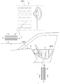
図1において、車両用内装材4は、自動車1の内装において、太陽や街灯などの外部からの光に照らされる被照射部としてのインストルメントパネル2やドアトリム3の表面に施されている。なお、被照射部は、例えば、コンビメーター周辺、コンソール、ピラーカバー、リアパーセルシェルフ、自動車用カメラカバー(それぞれ図示省略)などが含まれる。
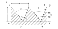
図2及び図3に示されているとおり、車両用内装材4は、表面である受光面5に無数の溝部6が形成され、表面がジグザグである。単一の溝部6の断面は、ほぼV字状であり、互いに対面した平坦な二つの反射面で構成されている。以下では、溝部6において、一方の反射面が第一反射面7、他方の反射面が第二反射面8、各反射面7,8同士の間隔が溝幅W、受光面5の垂線V方向が溝深さD、各反射面7,8の平面角が溝角度θ、受光面5と平行であって各反射面7,8の交点10を通る仮想面である平行面Pに対する第一反射面7の角度が第一外角度α、平行面Pに対する第二反射面8の角度が第二外角度β、溝部6が連続する方向が溝長さL(図1参照)とする。
溝部6は、垂線V上に、開口部9と各反射面7,8の交点10とが配置され、垂線Vに対して、各反射面7,8が、互いに相反する向きに傾斜している。第一反射面7は、屈折しており、溝部6の深さ方向において受光面5に近い側である平坦な浅面部11と、この浅面部11から深さ方向に伸びた平坦な深面部12とを有している。各反射面7,8の平面角は、浅面部11よりも深面部12の方が小さい(θ>θ1)。このような溝部6は、溝幅W方向に無数に隣接している。
なお、屈折の数は任意である。したがって、例えば、屈折の数が二つであれば、第一反射面部7は、三つの面部から構成され、屈折の数が三つであれば、第一反射面部7は、四つの面部から構成される。この場合、連接した各面部は、相対的に浅い側に配置されるものが浅面部11となり、相対的に深い側に配置されるものが深面部12となる。なお、第一反射面7および第二反射面8が、単一または複数屈折していてもよく、第二反射面8のみが、単一または複数屈折していてもよい。また、屈折の数は、溝幅W方向に隣接した溝部6毎に異なっていてもよい。また、各反射面7,8は、屈折せず、一様な平坦であってもよい。
溝幅Wは、例えば、30マイクロメートルである。溝深さDは、例えば、10から500マイクロメートルである。溝深さDが10マイクロメートル以下の場合、成形時に離型不良を起こす場合があり、一方で、溝深さDが500マイクロメートル以上の場合、被照射部の表面の凹凸が顕著となり、視覚的、感触的に適切ではない。溝角度θは、65度以下であり、具体的には、32から65度である。第一外角度αと第二外角度βとは、それぞれ異なり、概ね1:1~1.46である。例えば、溝角度θが32度であり、第一外角度αと第二外角度βとが1:1.46の場合、第一外角度αは約60.1度、第二外角度βは約87.9度である。図3に示されているとおり、溝角度θが65度の場合、第一外角度αは約46.7度、第二外角度βは68.3度である。この構成により、受光面5における反射率は、2.0パーセント以下となる。溝長さLは、被照射部の形状に応じて設計され、被照射部の端から端まで連続している(図1参照)。
各反射面7,8の向きは任意であり、例えば、図1に示されているとおり、被照射部のうち、車両において上方に向けられた部材であるインストルメントパネル2の受光面5では、各反射面7,8が、自動車1の全長方向に向けられている。また、例えば、被照射部のうち、自動車1における内側面に向けられた部材であるドアトリム2の受光面5では、各反射面7,8が、自動車1の全長方向と交差する方向に向けられている。
換言すれば、前者における溝長さLの方向は、インストルメントパネル2における車幅方向の端から端まで、後者における溝長さLの方向は、ドアトリム3における自動車1の全長方向の端から端までである。
また、図4に示されているとおり、例えば、インストルメントパネル2の受光面5では、各反射面7,8が、自動車1の全長方向と交差する方向に向けられてもよく、例えば、ドアトリム3の受光面5では、各反射面7,8が、自動車1の全長方向に向けられてもよい。
換言すれば、前者における溝長さLの方向は、インストルメントパネル2における自動車1の全長方向の端から端まで、後者における溝長さLの方向は、ドアトリム3における自動車1の車高方向の端から端までであってもよい。
さらに、各反射面7,8の向き(または溝長さLの方向)は、被照射部毎に異なっていてもよく、また、被照射部における任意の区画毎に異なっていてもよい。また、各反射面7,8の向きは、全長方向、車幅方向、車高方向に対して、直交し、または傾斜していてもよい。
車両用内装材4は、樹脂製であり、例えば、塩化ビニル、ポリプロピレン、ポリエステル、ポリカーボネート、ABS(Acrylonitril Butadiene Styrene)、アクリルなどである。車両用内装材4の色は、例えば、黒色系であるが、他の色であってもよい。車両用内装材4は、予め成形されたインストルメントパネル3などに後から施されてもよく、また、射出成形によって一体的に成形されていてもよい。射出成形における金型(図示省略)は、例えば2プレートであれば、可動型が溝部6に応じたジグザグである。溝部6の深さ方向は、可動型が開閉する方向に向けられている。
以上のとおり、車両用内装材4が構成されている。次に、本実施形態の効果を説明する。
上記したとおり、車両用内装材4に形成された溝部6の断面は、ほぼV字状であり、平坦な二つの第一反射面7及び第二反射面8で構成されている。溝部6は、溝角度θが32から65度、第一外角度αと第二外角度βとが概ね1:1~1.46である。この構成により、受光面5における反射率は、2.0パーセント以下となる。すなわち、溝部6における溝角度θが32から65度であれば、溝部6の各反射面7,8で反射した外部からの光は、反射を繰り返しながら溝部6の深さ方向に進み、減衰し、吸収される。したがって、外部への光の反射を抑え、搭乗者がどの角度からみても、搭乗者が感じる眩しさを低減することができる。また、垂線Vに対して第一外角度αと第二外角度βとが非対称であれば、搭乗者に向かわない方向に反射の向きを制御することができる。
車両用内装材4の溝部6は、垂線V上に、開口部9と各反射面7,8の交点10とが配置され、各反射面7,8が、互いに対面して相反する向きに傾斜している。溝部6の深さ方向は、金型が開閉する方向に向けられている。この構成によって、車両用内装材4が、射出成形によって製造される場合において、金型が開く際、金型において溝部6における交点10に対応する箇所が、交点10から開口部9まで、垂線V上を通って引き抜かれる。すなわち、金型を真っ直ぐに引き抜くことができるため、容易に射出成形することができる。
車両用内装材4の第一反射面7は、屈折しており、溝部6の深さ方向において受光面5に近い側である平坦な浅面部11と、この浅面部11から深さ方向に伸びた平坦な深面部12とを有している。各反射面7,8の平面角は、浅面部11よりも深面部12の方が小さい。この構成により、浅面部11で反射した外部からの光は、深面部12でさらに反射を繰り返し、減衰し、吸収される。したがって、外部への光の反射を抑え、搭乗者がどの角度からみても、搭乗者が感じる眩しさを低減することができる。
車両用内装材4では、各反射面7,8の向きは任意であり、例えば、溝長さLの方向は、インストルメントパネル2における車幅方向や全長方向などであってもよく、また、ドアトリム3における自動車1の全長方向や車高方向などであってもよい。すなわち、各反射面7,8がどの方向に向けられていても、搭乗者が感じる眩しさを低減することができる。
次に、本発明の実施例を説明する。
<実施例>
実施例及び比較例について、検証1、2及び3を実施した。各検証では、紫外可視近赤外分光光度計(島津製作所製、SolidSpec-3700)を用いた。検証1及び2では、相対全光線反射測定を実施し、検証3では、正反射による絶対反射率を測定した。なお、相対全光線反射測定は、JIS K 7375に準ずる。
実施例及び比較例について、検証1、2及び3を実施した。各検証では、紫外可視近赤外分光光度計(島津製作所製、SolidSpec-3700)を用いた。検証1及び2では、相対全光線反射測定を実施し、検証3では、正反射による絶対反射率を測定した。なお、相対全光線反射測定は、JIS K 7375に準ずる。
<検証1>
検証1では、溝角度θがそれぞれ異なる実施例1から5及び比較例を測定した。実施例及び比較例の仕様及び反射率は、下表1のとおりである。実施例ごとの反射率は、下表2のとおりである。
検証1では、溝角度θがそれぞれ異なる実施例1から5及び比較例を測定した。実施例及び比較例の仕様及び反射率は、下表1のとおりである。実施例ごとの反射率は、下表2のとおりである。


以上の結果から、溝角度θが、32から65度のとき、反射率が、約2.0以下であることがわかる。
<検証2>
検証2では、それぞれ異なる溝深さDが形成された実施例6から8を測定した。実施例の仕様及び反射率は、下表3のとおりである。
検証2では、それぞれ異なる溝深さDが形成された実施例6から8を測定した。実施例の仕様及び反射率は、下表3のとおりである。
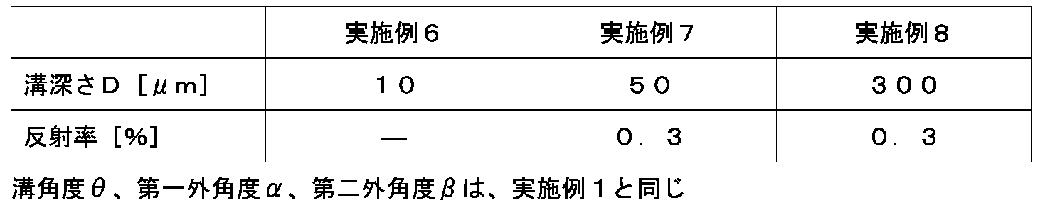
以上の結果から、検証2における範囲において、溝深さDは、反射率に影響しないことがわかる。
<検証3>
検証3では、検証1と同じ実施例及び比較例を測定した。受光面を基準とした角度である入射20ないし160度(入射角70ないしマイナス70度における絶対反射率は、下表4のとおりである。
検証3では、検証1と同じ実施例及び比較例を測定した。受光面を基準とした角度である入射20ないし160度(入射角70ないしマイナス70度における絶対反射率は、下表4のとおりである。

以上の結果から、様々な角度の入射光においても、反射率が約2.0%以下であることがわかる。
以上、本発明の実施形態を詳述したが、本発明は上記した実施形態に限定されるものではない。そして本発明は、特許請求の範囲に記載された事項を逸脱することがなければ、種々の設計変更を行うことが可能である。
1 自動車
2 インストルメントパネル(被照射部)
3 ドアトリム(被照射部)
4 車両用内装材
5 受光面
6 溝部
7 第一反射面
8 第二反射面
9 開口部
10 交点
11 浅面部
12 深面部
W 溝幅
θ 溝角度
V 垂線
D 溝深さ
L 溝長さ
P 平行面
α 第一外角度
β 第二外角度
2 インストルメントパネル(被照射部)
3 ドアトリム(被照射部)
4 車両用内装材
5 受光面
6 溝部
7 第一反射面
8 第二反射面
9 開口部
10 交点
11 浅面部
12 深面部
W 溝幅
θ 溝角度
V 垂線
D 溝深さ
L 溝長さ
P 平行面
α 第一外角度
β 第二外角度
Claims (8)
- 車両の内装において外部からの光に照らされる被照射部の受光面に、断面が、互いに対面した二つの平坦な反射面で構成された溝部を有し、
前記反射面の平面角が、65度以下である、
ことを特徴とする車両用内装材。 - 前記受光面と平行で、かつ、前記反射面の交点を通る面に対するそれぞれの前記反射面の角度が異なる、
ことを特徴とする請求項1に記載された車両用内装材。 - 前記受光面の垂線上に、前記溝部の開口部と前記反射面の交点とが配置され、
前記垂線に対して、前記反射面が、互いに相反する向きに傾斜した、
ことを特徴とする請求項1または請求項2に記載された車両用内装材。 - 少なくとも一方の前記反射面が、前記溝部の深さ方向において前記受光面に近い側である浅面部と、この浅面部から前記溝部の深さ方向に伸びた深面部とを有し、
前記浅面部よりも前記深面部の平面角が小さい、
ことを特徴とする請求項1から請求項3のいずれか1項に記載された車両用内装材。 - 前記受光面における反射率が、2.0パーセント以下である、
ことを特徴とする請求項1から請求項4のいずれか1項に記載された車両用内装材。 - 前記平面角が、32から65度である、
ことを特徴とする請求項1から請求項5のいずれか1項に記載された車両用内装材。 - 前記受光面のうち、前記車両において上方に向けられた上面部では、前記反射面が、前記車両の全長方向と交差する方向に向けられ、
前記受光面のうち、前記車両における内側面部では、前記反射面が、前記車両の全長方向と交差する方向に向けられた、
ことを特徴とする請求項1から請求項6のいずれか1項に記載された車両用内装材。 - 請求項1から請求項7のいずれか1項に記載された車両用内装材における前記溝部の深さ方向を、射出成形において金型が開閉する方向に向けた、
ことを特徴とする車両用内装材の製造方法。
Priority Applications (3)
| Application Number | Priority Date | Filing Date | Title |
|---|---|---|---|
| US17/618,639 US11981269B2 (en) | 2019-06-26 | 2020-06-16 | Vehicle interior member and vehicle interior member manufacturing method |
| EP20832968.0A EP3992008A4 (en) | 2019-06-26 | 2020-06-16 | VEHICLE INTERIOR COMPONENT AND METHOD OF MANUFACTURE OF VEHICLE INTERIOR COMPONENT |
| CN202080045414.XA CN114007889A (zh) | 2019-06-26 | 2020-06-16 | 车辆用内饰件以及车辆用内饰件的制造方法 |
Applications Claiming Priority (2)
| Application Number | Priority Date | Filing Date | Title |
|---|---|---|---|
| JP2019118244A JP7141982B2 (ja) | 2019-06-26 | 2019-06-26 | 車両用内装材及び車両用内装材の製造方法 |
| JP2019-118244 | 2019-06-26 |
Publications (1)
| Publication Number | Publication Date |
|---|---|
| WO2020262094A1 true WO2020262094A1 (ja) | 2020-12-30 |
Family
ID=74061982
Family Applications (1)
| Application Number | Title | Priority Date | Filing Date |
|---|---|---|---|
| PCT/JP2020/023513 WO2020262094A1 (ja) | 2019-06-26 | 2020-06-16 | 車両用内装材及び車両用内装材の製造方法 |
Country Status (5)
| Country | Link |
|---|---|
| US (1) | US11981269B2 (ja) |
| EP (1) | EP3992008A4 (ja) |
| JP (1) | JP7141982B2 (ja) |
| CN (1) | CN114007889A (ja) |
| WO (1) | WO2020262094A1 (ja) |
Citations (6)
| Publication number | Priority date | Publication date | Assignee | Title |
|---|---|---|---|---|
| JPH04138419A (ja) * | 1990-09-29 | 1992-05-12 | Hoya Corp | ディスプレイ用フィルタ |
| JPH0483853U (ja) * | 1990-11-29 | 1992-07-21 | ||
| US5316359A (en) * | 1993-03-08 | 1994-05-31 | Chrysler Corporation | Anti-reflective automotive interior instrument panel surface |
| JP2006011177A (ja) | 2004-06-28 | 2006-01-12 | Nissan Motor Co Ltd | 反射表皮材 |
| WO2011043117A1 (ja) * | 2009-10-05 | 2011-04-14 | 本田技研工業株式会社 | 車両用内装材 |
| US20140145252A1 (en) * | 2012-11-27 | 2014-05-29 | Lg Display Co., Ltd. | Thin Film Transistor Array Substrate for Digital Photo-Detector |
Family Cites Families (10)
| Publication number | Priority date | Publication date | Assignee | Title |
|---|---|---|---|---|
| US4756603A (en) * | 1986-01-31 | 1988-07-12 | Nippon Seiki Co., Ltd. | Glare-proof transparent cover plate |
| US5647629A (en) * | 1996-02-12 | 1997-07-15 | Collins; Richard M. | Reflection eliminator |
| JP2007079452A (ja) * | 2005-09-16 | 2007-03-29 | Three M Innovative Properties Co | 配光制御反射シート |
| JP4212636B1 (ja) * | 2007-12-21 | 2009-01-21 | 光正 武田 | 車両用内装材 |
| DE102008044972A1 (de) * | 2008-08-29 | 2010-03-04 | Daimler Ag | Fahrzeug mit gerichteter IR-Abstrahlung von einer Bauteiloberfläche |
| JP2011060714A (ja) * | 2009-09-14 | 2011-03-24 | Redbus Serraglaze Ltd | 昼光照明及びその他用途のための工学部品 |
| JP6627546B2 (ja) * | 2015-07-29 | 2020-01-08 | 大日本印刷株式会社 | 車両用内装材および車両用内装材用フィルム |
| JP5913714B1 (ja) * | 2015-10-19 | 2016-04-27 | 矢崎総業株式会社 | 車両表示装置用金属調装飾部品、及び、車両表示装置 |
| JP2019008203A (ja) * | 2017-06-27 | 2019-01-17 | 矢崎総業株式会社 | 車両用表示装置 |
| JP7103186B2 (ja) * | 2018-11-22 | 2022-07-20 | マツダ株式会社 | 樹脂製部材、樹脂製部材の成形用金型及び樹脂製部材の製造方法 |
-
2019
- 2019-06-26 JP JP2019118244A patent/JP7141982B2/ja active Active
-
2020
- 2020-06-16 US US17/618,639 patent/US11981269B2/en active Active
- 2020-06-16 CN CN202080045414.XA patent/CN114007889A/zh active Pending
- 2020-06-16 WO PCT/JP2020/023513 patent/WO2020262094A1/ja unknown
- 2020-06-16 EP EP20832968.0A patent/EP3992008A4/en active Pending
Patent Citations (6)
| Publication number | Priority date | Publication date | Assignee | Title |
|---|---|---|---|---|
| JPH04138419A (ja) * | 1990-09-29 | 1992-05-12 | Hoya Corp | ディスプレイ用フィルタ |
| JPH0483853U (ja) * | 1990-11-29 | 1992-07-21 | ||
| US5316359A (en) * | 1993-03-08 | 1994-05-31 | Chrysler Corporation | Anti-reflective automotive interior instrument panel surface |
| JP2006011177A (ja) | 2004-06-28 | 2006-01-12 | Nissan Motor Co Ltd | 反射表皮材 |
| WO2011043117A1 (ja) * | 2009-10-05 | 2011-04-14 | 本田技研工業株式会社 | 車両用内装材 |
| US20140145252A1 (en) * | 2012-11-27 | 2014-05-29 | Lg Display Co., Ltd. | Thin Film Transistor Array Substrate for Digital Photo-Detector |
Non-Patent Citations (1)
| Title |
|---|
| See also references of EP3992008A4 |
Also Published As
| Publication number | Publication date |
|---|---|
| EP3992008A1 (en) | 2022-05-04 |
| JP7141982B2 (ja) | 2022-09-26 |
| JP2021004966A (ja) | 2021-01-14 |
| EP3992008A4 (en) | 2023-07-05 |
| US11981269B2 (en) | 2024-05-14 |
| CN114007889A (zh) | 2022-02-01 |
| US20220258680A1 (en) | 2022-08-18 |
Similar Documents
| Publication | Publication Date | Title |
|---|---|---|
| CN102498006B (zh) | 遮挡车辆顶蓬的具有集成光引导装置的遮挡装置 | |
| EA022935B1 (ru) | Стекло с низким уровнем двойного изображения | |
| US20150210040A1 (en) | Cover for a motor vehicle roof | |
| JP5518989B2 (ja) | 車両用ドア | |
| JP6672275B2 (ja) | 自動車のガラス取り付けシステムのためのベゼル | |
| US10843440B2 (en) | Laminated glazing with recessed very thin interior glass | |
| WO2020262094A1 (ja) | 車両用内装材及び車両用内装材の製造方法 | |
| US6746126B2 (en) | Vehicle interior trim having a reduced glare effect at the windshield and the rear view window | |
| WO2017137297A1 (en) | Lighting device for vehicle cabin | |
| US10527759B2 (en) | Anti-glare panels | |
| EP2081786A1 (de) | Verschattungselement sowie verfahren zu dessen herstellung | |
| JP5882847B2 (ja) | 自動車用固定窓 | |
| JP6081416B2 (ja) | 外装部材及びその外装部材を備えた車両 | |
| US11577668B2 (en) | Interior component, motor vehicle and method for producing an interior component | |
| US7475932B2 (en) | Windscreen | |
| DE102011113627B4 (de) | Lichtscheibe für eine Fahrzeugleuchte und Fahrzeugleute mit einer solchen Lichtscheibe | |
| DE102016010579B4 (de) | Leuchte zur Raumbeleuchtung in einem Kraftfahrzeug | |
| US11852313B2 (en) | Light device of a vehicle to ensure a dark, or colored appearance of at least a part of the light device in the off state | |
| JP2005186385A (ja) | 反射表皮材 | |
| WO2021210471A1 (ja) | サッシュレスドアガラス、及びその製造方法 | |
| KR101585101B1 (ko) | 차량용 사이드 미러 | |
| EP3431449A1 (en) | Glass plate and glass structure | |
| DE102022109899A1 (de) | Anordnung und Panoramaglasdach | |
| CN116141935A (zh) | 用于车顶的透明的车顶面板组件 | |
| JP2021004966A5 (ja) |
Legal Events
| Date | Code | Title | Description |
|---|---|---|---|
| 121 | Ep: the epo has been informed by wipo that ep was designated in this application |
Ref document number: 20832968 Country of ref document: EP Kind code of ref document: A1 |
|
| NENP | Non-entry into the national phase |
Ref country code: DE |
|
| ENP | Entry into the national phase |
Ref document number: 2020832968 Country of ref document: EP Effective date: 20220126 |