WO2020261998A1 - モータ、圧縮機及びモータの製造方法 - Google Patents
モータ、圧縮機及びモータの製造方法 Download PDFInfo
- Publication number
- WO2020261998A1 WO2020261998A1 PCT/JP2020/022887 JP2020022887W WO2020261998A1 WO 2020261998 A1 WO2020261998 A1 WO 2020261998A1 JP 2020022887 W JP2020022887 W JP 2020022887W WO 2020261998 A1 WO2020261998 A1 WO 2020261998A1
- Authority
- WO
- WIPO (PCT)
- Prior art keywords
- peripheral wall
- outer peripheral
- wall portion
- stator
- insulator
- Prior art date
- Legal status (The legal status is an assumption and is not a legal conclusion. Google has not performed a legal analysis and makes no representation as to the accuracy of the status listed.)
- Ceased
Links
Images









Classifications
-
- H—ELECTRICITY
- H02—GENERATION; CONVERSION OR DISTRIBUTION OF ELECTRIC POWER
- H02K—DYNAMO-ELECTRIC MACHINES
- H02K3/00—Details of windings
- H02K3/32—Windings characterised by the shape, form or construction of the insulation
- H02K3/34—Windings characterised by the shape, form or construction of the insulation between conductors or between conductor and core, e.g. slot insulation
-
- H—ELECTRICITY
- H02—GENERATION; CONVERSION OR DISTRIBUTION OF ELECTRIC POWER
- H02K—DYNAMO-ELECTRIC MACHINES
- H02K7/00—Arrangements for handling mechanical energy structurally associated with dynamo-electric machines, e.g. structural association with mechanical driving motors or auxiliary dynamo-electric machines
- H02K7/14—Structural association with mechanical loads, e.g. with hand-held machine tools or fans
-
- F—MECHANICAL ENGINEERING; LIGHTING; HEATING; WEAPONS; BLASTING
- F04—POSITIVE - DISPLACEMENT MACHINES FOR LIQUIDS; PUMPS FOR LIQUIDS OR ELASTIC FLUIDS
- F04B—POSITIVE-DISPLACEMENT MACHINES FOR LIQUIDS; PUMPS
- F04B39/00—Component parts, details, or accessories, of pumps or pumping systems specially adapted for elastic fluids, not otherwise provided for in, or of interest apart from, groups F04B25/00 - F04B37/00
-
- H—ELECTRICITY
- H02—GENERATION; CONVERSION OR DISTRIBUTION OF ELECTRIC POWER
- H02K—DYNAMO-ELECTRIC MACHINES
- H02K1/00—Details of the magnetic circuit
- H02K1/06—Details of the magnetic circuit characterised by the shape, form or construction
- H02K1/22—Rotating parts of the magnetic circuit
- H02K1/27—Rotor cores with permanent magnets
- H02K1/2706—Inner rotors
- H02K1/272—Inner rotors the magnetisation axis of the magnets being perpendicular to the rotor axis
- H02K1/274—Inner rotors the magnetisation axis of the magnets being perpendicular to the rotor axis the rotor consisting of two or more circumferentially positioned magnets
- H02K1/2753—Inner rotors the magnetisation axis of the magnets being perpendicular to the rotor axis the rotor consisting of two or more circumferentially positioned magnets the rotor consisting of magnets or groups of magnets arranged with alternating polarity
- H02K1/276—Magnets embedded in the magnetic core, e.g. interior permanent magnets [IPM]
-
- H—ELECTRICITY
- H02—GENERATION; CONVERSION OR DISTRIBUTION OF ELECTRIC POWER
- H02K—DYNAMO-ELECTRIC MACHINES
- H02K15/00—Processes or apparatus specially adapted for manufacturing, assembling, maintaining or repairing of dynamo-electric machines
- H02K15/08—Forming windings by laying conductors into or around core parts
- H02K15/095—Forming windings by laying conductors into or around core parts by laying conductors around salient poles
-
- H—ELECTRICITY
- H02—GENERATION; CONVERSION OR DISTRIBUTION OF ELECTRIC POWER
- H02K—DYNAMO-ELECTRIC MACHINES
- H02K21/00—Synchronous motors having permanent magnets; Synchronous generators having permanent magnets
- H02K21/12—Synchronous motors having permanent magnets; Synchronous generators having permanent magnets with stationary armatures and rotating magnets
- H02K21/14—Synchronous motors having permanent magnets; Synchronous generators having permanent magnets with stationary armatures and rotating magnets with magnets rotating within the armatures
- H02K21/16—Synchronous motors having permanent magnets; Synchronous generators having permanent magnets with stationary armatures and rotating magnets with magnets rotating within the armatures having annular armature cores with salient poles
-
- H—ELECTRICITY
- H02—GENERATION; CONVERSION OR DISTRIBUTION OF ELECTRIC POWER
- H02K—DYNAMO-ELECTRIC MACHINES
- H02K3/00—Details of windings
- H02K3/30—Windings characterised by the insulating material
-
- H—ELECTRICITY
- H02—GENERATION; CONVERSION OR DISTRIBUTION OF ELECTRIC POWER
- H02K—DYNAMO-ELECTRIC MACHINES
- H02K3/00—Details of windings
- H02K3/46—Fastening of windings on the stator or rotor structure
- H02K3/52—Fastening salient pole windings or connections thereto
- H02K3/521—Fastening salient pole windings or connections thereto applicable to stators only
- H02K3/522—Fastening salient pole windings or connections thereto applicable to stators only for generally annular cores with salient poles
-
- H—ELECTRICITY
- H02—GENERATION; CONVERSION OR DISTRIBUTION OF ELECTRIC POWER
- H02K—DYNAMO-ELECTRIC MACHINES
- H02K9/00—Arrangements for cooling or ventilating
- H02K9/19—Arrangements for cooling or ventilating for machines with closed casing and closed-circuit cooling using a liquid cooling medium, e.g. oil
-
- F—MECHANICAL ENGINEERING; LIGHTING; HEATING; WEAPONS; BLASTING
- F25—REFRIGERATION OR COOLING; COMBINED HEATING AND REFRIGERATION SYSTEMS; HEAT PUMP SYSTEMS; MANUFACTURE OR STORAGE OF ICE; LIQUEFACTION SOLIDIFICATION OF GASES
- F25B—REFRIGERATION MACHINES, PLANTS OR SYSTEMS; COMBINED HEATING AND REFRIGERATION SYSTEMS; HEAT PUMP SYSTEMS
- F25B31/00—Compressor arrangements
- F25B31/02—Compressor arrangements of motor-compressor units
-
- H—ELECTRICITY
- H02—GENERATION; CONVERSION OR DISTRIBUTION OF ELECTRIC POWER
- H02K—DYNAMO-ELECTRIC MACHINES
- H02K2203/00—Specific aspects not provided for in the other groups of this subclass relating to the windings
- H02K2203/12—Machines characterised by the bobbins for supporting the windings
-
- H—ELECTRICITY
- H02—GENERATION; CONVERSION OR DISTRIBUTION OF ELECTRIC POWER
- H02K—DYNAMO-ELECTRIC MACHINES
- H02K2213/00—Specific aspects, not otherwise provided for and not covered by codes H02K2201/00 - H02K2211/00
- H02K2213/03—Machines characterised by numerical values, ranges, mathematical expressions or similar information
Definitions
- One aspect of the motor disclosed in the present application is a rotor, a stator that generates a magnetic field that rotates the rotor, a tubular insulator that is fixed to the axial end of the stator, and a stator that is wound around the stator via an insulator.
- the insulator is provided with a tubular outer peripheral wall portion and a plurality of insulators having one end connected to the inner peripheral surface of the outer peripheral wall portion and extending from one end portion in a rod shape in the radial direction of the outer peripheral wall portion.
- a suction pipe 11 for sucking the refrigerant and a discharge pipe 12 for discharging the compressed refrigerant are connected to the container 2.
- the shaft 3 as a rotation shaft is formed in a rod shape, and is arranged in the internal space 7 of the container 2 so that one end thereof is arranged in the oil sump 8.
- the shaft 3 is rotatably supported by the container 2 about the central axis of the cylinder forming the internal space 7. The shaft 3 rotates to supply the refrigerating machine oil stored in the oil reservoir 8 to the compression unit 5.
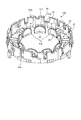
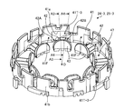
- FIG. 4 is a perspective view showing the upper insulator 24 in the first embodiment.
- the upper insulator 24 is formed in a cylindrical shape by an insulator exemplified by polybutylene terephthalate resin (PBT), and as shown in FIG. 4, a cylindrical outer peripheral wall portion 41 and a plurality of winding cylinder portions.
- the outer peripheral wall portion 41 is formed in a substantially cylindrical shape.
- a plurality of slits 44 are formed in the outer peripheral wall portion 41.
- the plurality of flange portions 43-1 to 43-9 correspond to the plurality of insulator teeth portions 42-1 to 42-9, and each of them is formed in a substantially semicircular plate shape.
- the first flange portion 43-1 corresponding to the first insulator teeth portion 42-1 of the plurality of flange portions 43-1 to 43-9 is continuously formed at the other end of the first insulator teeth portion 42-1.
- the collar portion different from the first flange portion 43-1 also has a plurality of insulator teeth portions 42-1 to 42-9, similarly to the first collar portion 43-1. It is continuously formed at the other end of the.
- the lower insulator 25 is also formed in the same manner as the upper insulator 24. That is, the lower insulator 25 is formed in a cylindrical shape by an insulator, and has an outer peripheral wall portion 41, a plurality of insulator teeth portions 42-1 to 42-9, and a plurality of flange portions 43-1 to 43-9. ,have.
- the plurality of insulator teeth portions 42-1 to 42-9 of the upper insulator 24 and the lower insulator 25 will be referred to as insulator teeth portions 42.
- a plurality of flange portions 43-1 to 43-9 of the upper insulator 24 and the lower insulator 25 are referred to as flange portions 43.
- the U-phase electric wire nozzle can appropriately move the upper insulator 24 and the lower insulator 25 attached to the stator 22 so that the U-phase electric wire can be arranged at a predetermined position with respect to the stator core 23.
- the V-phase electric wire nozzle By appropriately moving the V-phase electric wire nozzle with respect to the upper insulator 24 and the lower insulator 25 attached to the stator 22, the V-phase electric wire can be arranged at a predetermined position with respect to the stator core 23.
- the W-phase electric wire nozzle can appropriately move the upper insulator 24 and the lower insulator 25 attached to the stator 22 so that the W-phase electric wire can be arranged at a predetermined position with respect to the stator core 23.
- the winding machine is not limited to the configuration of the first embodiment, and a winding machine having only one nozzle may be used.
- the winding state in which the electric wire supplied from the nozzle N (hereinafter, also referred to as winding 46) is wound around the insulator teeth portion 42 of the upper insulator 24 and the lower insulator 25 will be described later.
- the compressor 1 is provided as a component of a refrigerating cycle device (not shown), and is used to compress the refrigerant and circulate the refrigerant in the refrigerant circuit of the refrigerating cycle device.
- the three-phase motor 6 has three phases in a plurality of U-phase power lines 48-U1 to 48-U3, a plurality of V-phase power lines 48-V1-48-V3, and a plurality of W-phase power lines 48-W1-48-W3.
- a rotating magnetic field is generated by applying each voltage.
- the rotor 21 is rotated by a rotating magnetic field generated by the stator 22.
- the three-phase motor 6 rotates the shaft 3 by rotating the rotor 21.
- the compression unit 5 sucks the low-pressure refrigerant gas through the suction pipe 11 by rotating the shaft 3, generates the high-pressure refrigerant gas by compressing the sucked low-pressure refrigerant gas, and raises the high-pressure refrigerant gas. It is supplied to the muffler chamber 16 and the lower muffler chamber 17.
- the lower muffler cover 15 reduces the pressure pulsation of the high-pressure refrigerant gas supplied to the lower muffler chamber 17, and supplies the high-pressure refrigerant gas with the reduced pressure pulsation to the upper muffler chamber 16.
- the upper muffler cover 14 reduces the pressure pulsation of the high-pressure refrigerant gas supplied to the upper muffler chamber 16, and the high-pressure refrigerant gas with the reduced pressure pulsation is used by the compression unit 5 and the three-phase motor 6 in the internal space 7. It is supplied to the space between them through the compressed refrigerant discharge hole 18.
- the high-pressure refrigerant gas supplied to the space between the compression unit 5 and the three-phase motor 6 in the internal space 7 passes through the gap formed in the three-phase motor 6 and thus is in the internal space 7. It is supplied to the space above the three-phase motor 6.
- the refrigerant supplied to the space above the three-phase motor 6 in the internal space 7 is discharged into the refrigerant circuit via the discharge pipe 12.
- one end of the insulator teeth portion 42 of the upper insulator 24 is connected to the inner peripheral surface 41a of the outer peripheral wall portion 41 and extends from one end portion inward in the radial direction of the outer peripheral wall portion 41.
- a flange portion 43 as an inner peripheral wall portion protrudes from the other end of the insulator teeth portion 42 in the axial direction of the stator 22 (axial direction of the shaft 3).
- the outer diameter side of the insulator teeth portion 42 is the outer diameter side of the insulator teeth portion side 41T
- the outer diameter side of the opening 47 between the adjacent flange portions 43 is the outer diameter side of the opening side. Let's call it part 41F. As shown in FIGS.
- the inner peripheral surface 41a and the outer peripheral surface 41b of the opening side outer peripheral wall portion 41F corresponding to each opening 47 are formed in an arc shape.
- the inner peripheral surface 41a and the outer peripheral surface 41b of the outer peripheral wall portion 41F on the opening side are not limited to the arc shape as described above.
- the height of the outer peripheral wall portion 41T on the insulator teeth portion side extending from the insulator teeth portion 42 in the axial direction of the stator 22 is formed to be larger than the height of the flange portion 43 extending in the axial direction of the stator 22 from the insulator teeth portion 42. Has been done.
- the outer peripheral wall portion 41T on the insulator teeth portion side which is formed to be thicker than the outer peripheral wall portion 41F on the opening side, has an insulator teeth from the insulator teeth portion 42 side toward the upper end side which is the tip in the axial direction of the stator 22.
- the outer peripheral wall portion 41T includes a portion formed with a small thickness.
- the outer peripheral wall portion 41T on the insulator teeth portion side has a base end thickness of t2 connected to the insulator teeth portion 42, and the thickness of the upper end on the opposite side to the stator 22. Is formed at t3.
- the base end of the outer peripheral wall portion 41T on the insulator teeth portion side refers to the root rising from the insulator teeth portion 42.
- the outer peripheral surface 41b of the outer peripheral wall portion 41T on the insulator teeth portion side has an angle r1 with respect to the axial direction of the stator 22, similarly to the outer peripheral surface 41b of the outer peripheral wall portion 41F on the opening side.
- the angle formed by the inner peripheral surface 41a of the outer peripheral wall portion 41T on the insulator teeth portion side with respect to the axial direction of the stator 22 is r3. That is, the outer peripheral wall portion 41T on the insulator teeth portion side is formed so that the thickness t3 at the upper end is smaller than the thickness t2 at the base end (t3 ⁇ t2). At this time, the angles and thicknesses of the outer peripheral wall portion 41F on the opening side and the outer peripheral wall portion 41T on the insulator teeth portion side are different.
- FIG. 9 is a plan view showing a state in which the winding 46 is wound around the insulator teeth portion 42 of the upper insulator 24 in the first embodiment by the nozzle N.
- FIG. 10 is an enlarged plan view showing the locus of the tip of the nozzle N in FIG.
- FIG. 11 is a plan view showing a state in which the winding 46 is wound around the insulator teeth portion 42 of the upper insulator 24 in the first embodiment.
- the winding machine is set with the upper insulator 24 and the lower insulator 25, and the stator core 23 to which an insulating film (not shown) is appropriately attached.
- the nozzle N extends along the radial direction of the outer peripheral wall portion 41, and the rotation center O of the nozzle N is located on a straight line along the radial direction of the outer peripheral wall portion 41. Further, in the circumferential direction of the outer peripheral wall portion 41, the center position of the outer peripheral wall portion 41F on the opening side and the center position of the outer peripheral wall portion 41T on the insulator teeth portion side (insulator teeth portion 42) with respect to the rotation center O of the nozzle N.
- the rotation angle formed by the center position is set to about 20 [°].
- the winding machine passes the nozzle N extended from the center side of the outer peripheral wall portion 41 of the upper insulator 24 beyond the upper portion of the flange portion 43 in the axial direction of the stator 22 so as to pass through the center of the outer peripheral wall portion 41. It is rotated around the rotation center O located on the side. That is, the nozzle N rotates in the circumferential direction of the inner peripheral surface 41a of the outer peripheral wall portion 41 so as not to come into contact with the flange portion 43.
- the nozzle N swivels along a plane orthogonal to the axial direction of the stator 22 from the outer peripheral wall portion 41F on the opening side toward the outer peripheral wall portion 41T on the insulator teeth portion side, so that the outer peripheral wall portion 41 In the circumferential direction, the winding 46 is wound so as to wind from the approach end 42A side as one end side in the circumferential direction of the insulator teeth portion 42 toward the exit end 42B side as the other end side in the circumferential direction of the insulator teeth portion 42. ..
- the nozzle N is in contact with the inner peripheral surface 41a of the outer peripheral wall portion 41 so that the winding 46 supplied from the nozzle N is in contact with the inner peripheral surface 41a of the outer peripheral wall portion 41 at the approach end 42A of the insulator teeth portion 42.
- Nozzle N exits.
- a gap G is secured between the tip of the nozzle N and the inner peripheral surface 41a at the center of the insulator teeth portion 42 in the circumferential direction of the outer peripheral wall portion 41.
- the gap G is secured when it moves to a position where it slightly overlaps the insulator teeth portion 42 when viewed from the axial direction.
- the position of the tip of the nozzle N that turns from the approach end 42A side of the insulator teeth portion 42 can reach the vicinity of the inner peripheral surface 41a of the outer peripheral wall portion 41 and start winding. Therefore, the position where the winding 46 starts to be wound from the approach end 42A of the insulator teeth portion 42 is close to the inner peripheral surface 41a of the outer peripheral wall portion 41.
- the aligned winding means that the windings 46 of each layer laminated on the winding portion 45 are stacked and wound with a deviation of 1/2 pitch of the diameter of the windings 46.
- FIG. 12 is a vertical cross-sectional view showing the shape of the insulator teeth portion 42 of the upper insulator 24 in the first embodiment.
- FIG. 13 is a vertical cross-sectional view showing another shape of the insulator teeth portion 42 of the upper insulator 24 in the first embodiment.
- FIG. 12 is a vertical cross-sectional view taken along the line QQ in FIGS. 4 and 6.
- FIG. 13 is a vertical cross-sectional view showing another shape of the insulator teeth portion 42 in the same manner as in FIG.
- the peripheral surface 42a of the insulator teeth portion 42 has a thickness of the insulator teeth portion 42 in the axial direction of the stator 22 at both ends of the insulator teeth portion 42 in the circumferential direction of the outer peripheral wall portion 41 (entrance end 42A). It is formed in a so-called semi-cylindrical shape having a curved surface that increases from the exit end 42B) toward the center.
- the insulator teeth portion 42 supports the outer peripheral wall portion 41, so that the outer peripheral wall portion 41 is further prevented from falling inward in the radial direction of the outer peripheral wall portion 41.
- peripheral surface 42a around which the winding 46 is wound in the insulator teeth portion 42 is not limited to a curved surface protruding toward the upper end side of the outer peripheral wall portion 41, and may be formed on a flat surface as shown in FIG.
- FIG. 14 is a perspective view showing the upper insulator in the comparative example.
- FIG. 15 is a plan view showing a state in which the nozzle N is rotated toward the insulator teeth portion of the upper insulator in the comparative example. Also in the upper insulator in the comparative example, the same parts as those of the upper insulator 24 in the first embodiment are designated by the same reference numerals, and the description thereof will be omitted.
- FIG. 16 is a plan view showing a state in which the winding 46 is wound around the insulator teeth portion 42 of the upper insulator 124 in the comparative example by the nozzle N.
- FIG. 17 is a plan view showing a state in which the winding 46 is wound around the insulator teeth portion 42 of the upper insulator 124 in the comparative example.
- the thickness of the outer peripheral wall portion 41T on the insulator teeth portion side in the radial direction is a group close to the stator 22 in the axial direction of the stator 22.
- the upper end side far from the stator 22 side is smaller than the end side, and the thickness t2 on the base end side of the outer peripheral wall portion 41T on the insulator teeth portion side is larger than the thickness t1 on the outer peripheral wall portion 41F on the opening side.
- the same components as those in the first embodiment are designated by the same reference numerals as those in the first embodiment, and the description thereof will be omitted.
- the shape of the inner peripheral surface 41a of the outer peripheral wall portion 41T on the insulator teeth portion side of the upper insulator 24 and the lower insulator 25 is the same as the shape of the inner peripheral surface 41a of the outer peripheral wall portion 41T on the insulator teeth portion side in the first embodiment. different.
- FIG. 18 is a perspective view showing the upper insulator in the second embodiment.
- FIG. 19 is a plan view showing a main part of the upper insulator in the second embodiment.
- FIG. 20 is a vertical cross-sectional view showing the shape of the outer peripheral wall portion 41 of the upper insulator in the second embodiment.
- FIG. 20 is a vertical cross-sectional view taken along the line A2-A2 in FIG.
- the outer peripheral wall portion 41 of the upper insulator 24-2 in the second embodiment the outer peripheral wall portion 41T-2 on the insulator teeth portion side having the step portion 41Ta is formed, so that the outer peripheral wall portion 41T-2 on the insulator teeth portion side It is possible to increase the thickness of the insulator teeth portion 42 side (stator 22 side). Therefore, the mechanical strength of the insulator teeth portion side outer peripheral wall portion 41T-2 can be further increased as compared with the insulator teeth portion side outer peripheral wall portion 41T in the first embodiment. Therefore, also in the second embodiment, as in the first embodiment, it is possible to prevent the outer peripheral wall portion 41 from falling inward in the radial direction of the outer peripheral wall portion 41.
- the shape of the inner peripheral surface 41a of the outer peripheral wall portion on the insulator teeth portion side of the upper insulator 24 and the lower insulator 25 is the inner circumference of the outer peripheral wall portions 41T and 41T-2 on the insulator teeth portion side in Examples 1 and 2. It is different from the shape of the surface 41a.
- FIG. 21 is a perspective view showing the upper insulator in the third embodiment.
- 22 and 23 are vertical cross-sectional views showing the shape of the outer peripheral wall portion 41 of the upper insulator in the third embodiment.
- FIG. 22 is a vertical cross-sectional view taken along the line A3-A3 in FIG. 21, and is a vertical cross-sectional view of the insulator teeth portion 42 on the approach end 42A side.
- FIG. 23 is a vertical cross-sectional view taken along the line A4-A4 in FIG. 21, and is a vertical cross-sectional view of the insulator teeth portion 42 on the exit end 42B side.
- the A3-A3 line and the A4-A4 line are cutting lines that pass through the rotation center O of the nozzle N and are along the radial direction of the upper insulator.
- the outer peripheral wall portion 41 of the upper insulator 24-3 in the third embodiment has an outer peripheral wall portion 41T-3 on the insulator teeth portion side.
- the thickness of the outer peripheral wall portion 41T-3 on the insulator teeth portion side differs between the approach end 42A side and the exit end 42B side of the insulator teeth portion 42 in the circumferential direction, and the exit end 42B on the outer peripheral wall portion 41T-3 on the insulator teeth portion side.
- the thickness on the side is larger than the thickness on the approach end 42A side.
- the inner peripheral surface 41a of the outer peripheral wall portion 41T-3 on the insulator teeth portion side has an approach end of the insulator teeth portion 42 in the circumferential direction of the outer peripheral wall portion 41T-3 on the insulator teeth portion side.
- the first shape portion 41TA is formed on the 42A side
- the second shape portion 41TB is formed on the exit end 42B side of the insulator teeth portion 42.
- the first shape portion 41TA and the second shape portion 41TB are bounded by a straight line passing through the center of the insulator teeth portion 42 in the circumferential direction of the outer peripheral wall portion 41T-3 on the insulator teeth portion side and along the radial direction of the outer peripheral wall portion 41.
- the outer peripheral wall portion 41T-3 on the insulator teeth portion side is formed in an asymmetrical shape.
- the tip of the nozzle N that swivels with respect to the inner peripheral surface 41a of the outer peripheral wall portion 41 after the nozzle N passes through the center of the insulator teeth portion 42 in the circumferential direction of the outer peripheral wall portion 41. Since it rotates so as to move away from the inner peripheral surface 41a, there is room for increasing the thickness of the outer peripheral wall portion 41 on the exit end 42B side of the insulator teeth portion 42. Therefore, in the outer peripheral wall portion 41T-3 on the insulator teeth portion side in the third embodiment, the first shape portion 41TA is formed on the approach end 31A side of the insulator teeth portion 42, and the first shape portion 41TA is formed on the exit end 42B side of the insulator teeth portion 42.
- the second shape portion 41TB capable of increasing the thickness of the outer peripheral wall portion 41T-3 on the insulator teeth portion side as compared with the first shape portion 41TA, the outer circumference on the insulator teeth portion side on the exit end 42B side is formed.
- the thickness of the wall portion 41T-3 it is possible to suppress a decrease in the mechanical strength of the outer peripheral wall portion 41T-3 on the insulator teeth portion side.
Landscapes
- Engineering & Computer Science (AREA)
- Power Engineering (AREA)
- Mechanical Engineering (AREA)
- General Engineering & Computer Science (AREA)
- Manufacturing & Machinery (AREA)
- Physics & Mathematics (AREA)
- Thermal Sciences (AREA)
- Insulation, Fastening Of Motor, Generator Windings (AREA)
- Manufacture Of Motors, Generators (AREA)
- Compressor (AREA)
- Connection Of Motors, Electrical Generators, Mechanical Devices, And The Like (AREA)
Abstract
モータのインシュレータ(24、25)は、外周壁部(41)において、巻胴部(42)の外径側を巻胴部側外周壁部(41T)とし、開口部(47)の外径側を開口部側外周壁部(41F)としたとき、巻胴部側外周壁部(41T)の径方向における厚さは、ステータの軸方向においてステータに近い基端側よりも、ステータ側から遠い先端側が小さくなると共に、巻胴部側外周壁部(41T)の基端側の厚さは、開口部側外周壁部(41F)の厚さよりも大きい。
Description
本発明は、モータ、圧縮機及びモータの製造方法に関する。
例えば、圧縮機は、冷媒を圧縮する圧縮部を駆動するためのモータを備えている。モータは、永久磁石が設けられたロータと、回転磁界を発生することによりロータを回転させるステータと、を備えており、ロータに固定された回転軸を介して圧縮部に回転動力を伝達する。ステータの軸方向の端面にはインシュレータが設けられている。インシュレータは、筒状の外周壁部と、外周壁部の内周面から外周壁部の径方向に延びる複数の巻胴部と、巻胴部に形成された内周壁部と、を有する。インシュレータの各巻胴部は、ステータが有する複数のティースの各々に重ねられて、ノズルから供給された電線が、巻胴部を介してティースに巻き付けられることにより巻き線が形成される。
インシュレータの巻胴部に巻き線を巻回する場合、インシュレータの径方向の中心側から、巻胴部の内周壁を越えて外周壁部に向かって先端が延ばされたノズルを、インシュレータの径方向の中心側に位置する回転中心まわりに回動させることで、外周壁部の周方向における巻胴部の一端側から他端側に向かって、巻き線を供給するノズルの先端を旋回させて、巻き線を巻胴部に巻回することが考えられる。この場合、ノズルの先端と外周壁部の内周面との接触を避けるようにノズルを旋回させる位置関係に起因して、外周壁の径方向において巻胴部に巻き線を巻き始める開始位置が、インシュレータの中心側にずれてしまう。すなわち、外周壁部の内周面に沿う位置から、巻き線を巻胴部に巻き始めることができない。このため、巻胴部における外周壁部の内周面側には、巻き線と内周面との間に空隙が生じるので、巻胴部における巻き線の巻回状態が整列巻きにならず、巻き線の占積率の低下を招く。
開示の技術は、上記に鑑みてなされたものであって、インシュレータの巻き線の占積率を向上することができるモータ、圧縮機及びモータの製造方法を提供することを目的とする。
本願の開示するモータの一態様は、ロータと、ロータを回転させる磁界を発生するステータと、ステータの軸方向の端部に固定される筒状のインシュレータと、インシュレータを介してステータに巻回される巻き線と、を備え、インシュレータは、筒状の外周壁部と、外周壁部の内周面に一端部が連結されて一端部から外周壁部の径方向に向かって棒状に延びる複数の巻胴部と、前記巻胴部の他端部からステータの軸方向に突出して形成された複数の内周壁部と、周方向に隣接する内周壁部の間に形成された開口部と、を有し、外周壁部において、巻胴部の外径側を巻胴部側外周壁部とし、開口部の外径側を開口部側外周壁部としたとき、巻胴部側外周壁部の径方向における厚さは、ステータの軸方向においてステータに近い基端側よりも、ステータ側から遠い先端側が小さくなると共に、巻胴部側外周壁部の基端側の厚さは、開口部側外周壁部の厚さよりも大きい。
本願の開示するモータの一態様によれば、インシュレータの巻き線の占積率を向上することができる。
以下に、本願の開示するモータ、圧縮機及びモータの製造方法の実施例を図面に基づいて詳細に説明する。なお、以下の実施例によって、本願の開示するモータ、圧縮機及びモータの製造方法が限定されるものではない。
図1は、実施例1の3相モータを備える圧縮機を示す縦断面図である。図1に示すように、圧縮機1は、いわゆるロータリ圧縮機であり、容器2と、シャフト3と、圧縮部5と、3相モータ6と、を備えている。容器2は、金属材料によって形成されており、密閉された内部空間7を形成している。内部空間7は、概ね円柱状に形成されている。容器2は、水平面上に縦置きされたときに、内部空間7をなす円柱の中心軸が鉛直方向に平行になるように形成されている。容器2には、内部空間7の下部に油溜め8が形成されている。油溜め8には、圧縮部5を潤滑させる潤滑油である冷凍機油が貯留される。容器2には、冷媒を吸入するための吸入管11と、圧縮された冷媒を吐出する吐出管12と、が接続されている。回転軸としてのシャフト3は、棒状に形成されており、一端が油溜め8に配置されるように、容器2の内部空間7に配置されている。シャフト3は、内部空間7をなす円柱の中心軸を中心に回転可能に容器2に支持されている。シャフト3は、回転することにより、油溜め8に貯留された冷凍機油を圧縮部5に供給する。
圧縮部5は、内部空間7の下部に配置され、油溜め8の上方に配置されている。圧縮機1は、さらに、上マフラーカバー14と、下マフラーカバー15と、を備えている。上マフラーカバー14は、内部空間7のうちの圧縮部5の上部に配置されている。上マフラーカバー14は、内部に上マフラー室16を形成している。下マフラーカバー15は、内部空間7における圧縮部5の下部に設けられており、油溜め8の上部に配置されている。下マフラーカバー15は、内部に下マフラー室17を形成している。下マフラー室17は、圧縮部5に形成されている連通路(図示せず)を介して上マフラー室16に連通している。上マフラーカバー14とシャフト3との間には、圧縮冷媒吐出孔18が形成され、上マフラー室16は、圧縮冷媒吐出孔18を介して内部空間7に連通している。
圧縮部5は、シャフト3が回転することにより吸入管11から供給される冷媒を圧縮し、その圧縮された冷媒を上マフラー室16と下マフラー室17とに供給する。その冷媒は、冷凍機油と相溶性を有している。3相モータ6は、内部空間7のうちの圧縮部5の上方に配置されている。
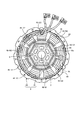
図2は、実施例1における3相モータ6を上インシュレータ側から示す平面図である。図1及び図2に示すように、3相モータ6は、ロータ21と、ステータ22と、を備えている。ロータ21は、珪素鋼の薄板(磁性体)を複数積層して円柱状に形成されており、複数のリベット9により一体化されている。ロータ21の中心にシャフト3が挿通され、固定されている。ロータ21には、6個のスリット状の磁石埋め込み孔10aが、シャフト3を中心として6角形の各辺をなすように形成されている。各磁石埋め込み孔10aは、ロータ21の周方向に所定間隔をあけて形成されている。磁石埋め込み孔10aには、板状の永久磁石10bが埋め込まれている。
ステータ22は、概ね円筒形に形成されており、ロータ21を囲むように配置されて、容器2に固定されている。ステータ22は、ステータコア23と、上インシュレータ24及び下インシュレータ25と、複数の巻き線46と、を備えている。上インシュレータ24は、ステータコア23の上端部に固定されている。下インシュレータ25は、ステータコア23の下端部に固定されている。上インシュレータ24及び下インシュレータ25は、ステータコア23と巻き線46とを絶縁する絶縁部の一例である。
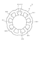
図3は、実施例1におけるステータコア23を示す下面図である。ステータコア23は、例えば、ケイ素鋼板に例示される軟磁性体で形成された複数の板が積層されて形成され、図3に示すように、ヨーク部31と、複数のステータコアティース部32-1~32-9と、を備えている。ヨーク部31は、概ね円筒形に形成されている。複数のステータコアティース部32-1~32-9のうちの第1ステータコアティース部32-1は、概ね柱体状に形成されている。第1ステータコアティース部32-1は、一端がヨーク部31の内周面に連続して形成され、すなわち、ヨーク部31の内周面からステータコア23の中心軸に向かって突出するように形成されている。複数のステータコアティース部32-1~32-9のうちの第1ステータコアティース部32-1と異なるステータコアティース部も、第1ステータコアティース部32-1と同様に、概ね柱体状に形成されており、ヨーク部31の内周面からステータコア23の中心軸に向かって突出している。複数のステータコアティース部32-1~32-9は、さらに、ヨーク部31の内周面に40度ごとの等間隔に配置されて形成されている。
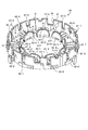
図4は、実施例1における上インシュレータ24を示す斜視図である。上インシュレータ24は、ポリブチレンテレフタレート樹脂(PBT)に例示される絶縁体によって円筒状に形成されており、図4に示すように、円筒状の外周壁部41と、巻胴部としての複数のインシュレータティース部42-1~42-9と、内周壁部としての複数の鍔部43-1~43-9と、上インシュレータ24の周方向に隣接する鍔部43-1~43-9同士の間に形成された開口部47-1~47-9と、を有している。外周壁部41は、概ね円筒形に形成されている。外周壁部41には、複数のスリット44が形成されている。複数のインシュレータティース部42-1~42-9のうちの第1インシュレータティース部42-1は、断面が概ね半円である直柱体状に形成されている。第1インシュレータティース部42-1は、一端が外周壁部41の内周面に連続して形成され、すなわち、外周壁部41の内周面から外周壁部41の径方向に向かって棒状に伸びるように形成されている。複数のインシュレータティース部42-1~42-9のうちの第1インシュレータティース部42-1と異なるインシュレータティース部も、直柱体状に形成され、第1インシュレータティース部42-1と同様に、外周壁部41の内周面から外周壁部41の径方向に向かって棒状に伸びるように形成されている。複数のインシュレータティース部42-1~42-9は、外周壁部41の内周面に40度ごとの等間隔に配置されて形成されている。
複数の鍔部43-1~43-9は、複数のインシュレータティース部42-1~42-9に対応し、それぞれ、概ね半円形の板状に形成されている。複数の鍔部43-1~43-9のうちの第1インシュレータティース部42-1に対応する第1鍔部43-1は、第1インシュレータティース部42-1の他端に連続して形成されている。複数の鍔部43-1~43-9のうちの第1鍔部43-1と異なる鍔部も、第1鍔部43-1と同様に、複数のインシュレータティース部42-1~42-9の他端に連続して形成されている。
下インシュレータ25も、上インシュレータ24と同様に形成されている。すなわち、下インシュレータ25は、絶縁体によって円筒状に形成されており、外周壁部41と、複数のインシュレータティース部42-1~42-9と、複数の鍔部43-1~43-9と、を有している。以下、上インシュレータ24及び下インシュレータ25の複数のインシュレータティース部42-1~42-9を、インシュレータティース部42と称する。また、上インシュレータ24及び下インシュレータ25の複数の鍔部43-1~43-9を、鍔部43と称する。
図5は、実施例1におけるステータ22を示す下面図である。ステータコア23の複数のステータコアティース部32-1~32-9には、図5に示すように、電線である巻き線46がそれぞれ巻回されている。各ステータコアティース部32-1~32-9には、各巻き線46によって巻回部45がそれぞれ形成されている。実施形態における3相モータは、6極9スロットの集中巻型のモータである(図2参照)。複数の巻き線46は、複数のU相巻き線46-U1~46-U3と、複数のV相巻き線46-V1~46-V3と、複数のW相巻き線46-W1~46-W3と、を備えている。また、ステータ22において、各巻回部45から引き出されて一束にまとめられた中性線は、絶縁チューブで覆われて、ステータ22の周方向(ロータ21の回転方向)に隣り合う巻回部45の隙間に挿入されている(図2参照)。以下、ステータコア23の複数のステータコアティース部32-1~32-9を、ステータコアティース部32と称する。
[ステータの製造方法]
ステータ22は、巻線機を用いて、上インシュレータ24及び下インシュレータ25が適切に取り付けられたステータコア23に、U相電線、V相電線及びW相電線が適切に配置されることにより、製作される。電線は、例えば、エナメル線(銅線をエナメルの被膜で被覆した電線)である。巻線機は、例えば、U相電線用ノズルと、V相電線用ノズルと、W相電線用ノズルと、を備えている。U相電線用ノズル、V相電線用ノズル及びW相電線用ノズルは、互いに固定されている。U相電線用ノズルは、ステータ22に取り付けられた上インシュレータ24及び下インシュレータ25に対して、適切に移動することにより、U相電線をステータコア23に対して所定の位置に配置させることができる。V相電線用ノズルは、ステータ22に取り付けられた上インシュレータ24及び下インシュレータ25に対して、適切に移動することにより、V相電線をステータコア23に対して所定の位置に配置させることができる。W相電線用ノズルは、ステータ22に取り付けられた上インシュレータ24及び下インシュレータ25に対して、適切に移動することにより、W相電線をステータコア23に対して所定の位置に配置させることができる。なお、巻線機は、実施例1の構成に限られず、1本のノズルのみを備えるものが用いられてもよい。ノズルNから供給される電線(以下、巻き線46とも称する。)が、上インシュレータ24及び下インシュレータ25のインシュレータティース部42に巻回される巻回状態については後述する。
ステータ22は、巻線機を用いて、上インシュレータ24及び下インシュレータ25が適切に取り付けられたステータコア23に、U相電線、V相電線及びW相電線が適切に配置されることにより、製作される。電線は、例えば、エナメル線(銅線をエナメルの被膜で被覆した電線)である。巻線機は、例えば、U相電線用ノズルと、V相電線用ノズルと、W相電線用ノズルと、を備えている。U相電線用ノズル、V相電線用ノズル及びW相電線用ノズルは、互いに固定されている。U相電線用ノズルは、ステータ22に取り付けられた上インシュレータ24及び下インシュレータ25に対して、適切に移動することにより、U相電線をステータコア23に対して所定の位置に配置させることができる。V相電線用ノズルは、ステータ22に取り付けられた上インシュレータ24及び下インシュレータ25に対して、適切に移動することにより、V相電線をステータコア23に対して所定の位置に配置させることができる。W相電線用ノズルは、ステータ22に取り付けられた上インシュレータ24及び下インシュレータ25に対して、適切に移動することにより、W相電線をステータコア23に対して所定の位置に配置させることができる。なお、巻線機は、実施例1の構成に限られず、1本のノズルのみを備えるものが用いられてもよい。ノズルNから供給される電線(以下、巻き線46とも称する。)が、上インシュレータ24及び下インシュレータ25のインシュレータティース部42に巻回される巻回状態については後述する。
[圧縮機の動作]
圧縮機1は、図示しない冷凍サイクル装置の構成要素として設けられており、冷媒を圧縮して、冷凍サイクル装置の冷媒回路に冷媒を循環させるために使用される。3相モータ6は、複数のU相電源線48-U1~48-U3、複数のV相電源線48-V1~48-V3及び複数のW相電源線48-W1~48-W3に三相電圧がそれぞれ印加されることにより、回転磁界を発生させる。ロータ21は、ステータ22により発生された回転磁界によって回転する。3相モータ6は、ロータ21が回転することにより、シャフト3を回転させる。
圧縮機1は、図示しない冷凍サイクル装置の構成要素として設けられており、冷媒を圧縮して、冷凍サイクル装置の冷媒回路に冷媒を循環させるために使用される。3相モータ6は、複数のU相電源線48-U1~48-U3、複数のV相電源線48-V1~48-V3及び複数のW相電源線48-W1~48-W3に三相電圧がそれぞれ印加されることにより、回転磁界を発生させる。ロータ21は、ステータ22により発生された回転磁界によって回転する。3相モータ6は、ロータ21が回転することにより、シャフト3を回転させる。
圧縮部5は、シャフト3が回転することで、吸入管11を介して低圧冷媒ガスを吸入し、その吸入された低圧冷媒ガスを圧縮することにより高圧冷媒ガスを生成し、高圧冷媒ガスを上マフラー室16と下マフラー室17とに供給する。下マフラーカバー15は、下マフラー室17に供給された高圧冷媒ガスの圧力脈動を低減し、圧力脈動が低減された高圧冷媒ガスを上マフラー室16に供給する。上マフラーカバー14は、上マフラー室16に供給された高圧冷媒ガスの圧力脈動を低減し、圧力脈動が低減された高圧冷媒ガスを内部空間7のうちの圧縮部5と3相モータ6との間の空間に圧縮冷媒吐出孔18を介して供給する。
内部空間7のうちの圧縮部5と3相モータ6との間の空間に供給された高圧冷媒ガスは、3相モータ6に形成されている隙間を通過することにより、内部空間7のうちの3相モータ6より上の空間に供給される。内部空間7のうちの3相モータ6より上の空間に供給された冷媒は、吐出管12を介して、冷媒回路内に吐出される。
[圧縮機の特徴的な構成]
次に、実施例1における3相モータ6の特徴的な構成について説明する。実施例1の特徴には、上インシュレータ24及び下インシュレータ25のインシュレータティース部42近傍における外周壁部41の内周面41aの形状が含まれる。以下、上インシュレータ24について説明するが、下インシュレータ25についても同様である。
次に、実施例1における3相モータ6の特徴的な構成について説明する。実施例1の特徴には、上インシュレータ24及び下インシュレータ25のインシュレータティース部42近傍における外周壁部41の内周面41aの形状が含まれる。以下、上インシュレータ24について説明するが、下インシュレータ25についても同様である。
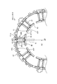
図6は、実施例1における上インシュレータの要部を示す平面図である。図7及び図8は、実施例1における上インシュレータの外周壁部の形状を示す縦断面図である。図7は、図6におけるB-B線に沿う縦断面図である。図8は、図6におけるA1-A1線に沿う縦断面図である。
図4及び図6に示すように、上インシュレータ24のインシュレータティース部42は、外周壁部41の内周面41aに一端部が連結されて一端部から外周壁部41の径方向の内側に延びており、インシュレータティース部42の他端部から、内周壁部としての鍔部43がステータ22の軸方向(シャフト3の軸方向)に突出して形成されている。ここで、外周壁部41において、インシュレータティース部42の外径側をインシュレータティース部側外周壁部41Tとし、隣接する鍔部43同士の間の開口部47の外径側を開口部側外周壁部41Fとする。図6及び図7に示すように、各開口部47に対応する開口部側外周壁部41Fの内周面41aと外周面41bが円弧状に形成されている。開口部側外周壁部41Fの内周面41aと外周面41bは、上述のような円弧状に限定されない。また、インシュレータティース部42から、ステータ22の軸方向に延びるインシュレータティース部側外周壁部41Tの高さは、インシュレータティース部42から、ステータ22の軸方向に延びる鍔部43の高さよりも大きく形成されている。
開口部側外周壁部41Fの内周面41aが円弧状に形成されることで、ノズルNの先端を旋回させてノズルNから供給される巻き線46をインシュレータティース部42に巻回する際に、インシュレータティース部42に巻かれる巻き線46の長手方向(巻き線46の巻回方向)と、開口部側外周壁部41Fの内周面41aとが平行になるので、ノズルNの先端と外周壁部41との接触を避けつつノズルNの先端を外周壁部41の内周面41aに近づけた位置から、巻き線46をインシュレータティース部42に巻き始めることが可能となる。
また、図4、図6及び図8に示すように、上インシュレータ24の外周壁部41において、各インシュレータティース部42に対応するインシュレータティース部側外周壁部41Tは、各インシュレータティース部42の間における開口部側外周壁部41Fの径方向における厚さ(以下、開口部側外周壁部41Fの厚さと称する。)に比べて、外周壁部41の厚さを増やした肉厚部として形成されている。開口部側外周壁部41Fよりも厚さが大きく形成されたインシュレータティース部側外周壁部41Tは、ステータ22の軸方向において、インシュレータティース部42側から先端である上端側に向かって、インシュレータティース部外周壁部41Tの厚さが小さく形成されている部分を含む。
図7に示すように、開口部側外周壁部41Fは、ステータ22側の下端の厚さがt1に形成されており、ステータ22と反対側の上端の厚さがt4に形成されている。ここで、開口部側外周壁部41Fの外周面41bが、ステータ22の軸方向に対してなす角度をr1とし、開口部側外周壁部41Fの内周面41aが、ステータ22の軸方向に対してなす角度をr2とする。すなわち、開口部側外周壁部41Fは、上端の厚さt4が、下端の厚さt1よりも小さく形成されている(t4<t1)。また、図8に示すように、インシュレータティース部側外周壁部41Tは、インシュレータティース部42に連結された基端の厚さがt2に形成されており、ステータ22と反対側の上端の厚さがt3に形成されている。インシュレータティース部側外周壁部41Tの基端は、インシュレータティース部42から立ち上がる根元を指す。インシュレータティース部側外周壁部41Tの外周面41bは、開口部側外周壁部41Fの外周面41bと同様に、ステータ22の軸方向に対して角度r1をなしている。ここで、インシュレータティース部側外周壁部41Tの内周面41aが、ステータ22の軸方向に対してなす角度をr3とする。すなわち、インシュレータティース部側外周壁部41Tは、上端の厚さt3が、基端の厚さt2よりも小さく形成されている(t3<t2)。このとき、開口部側外周壁部41Fとインシュレータティース部側外周壁部41Tにおける各角度、厚さは、
r3>r2≧r1 ・・・(式1)
t1<t2 ・・・(式2)
t3≦t4 ・・・(式3)
をそれぞれ満たす。
r3>r2≧r1 ・・・(式1)
t1<t2 ・・・(式2)
t3≦t4 ・・・(式3)
をそれぞれ満たす。
また、図7及び図8に示すように、インシュレータティース部側外周壁部41Tの上端の厚さt3は、基端の厚さt2よりも小さく形成されている。また、開口部側外周壁部41Fの下端の厚さt1以下に形成されている(t3≦t1<t2)。
すなわち、外周壁部41の周方向において、インシュレータティース部側外周壁部41Tの基端の厚さt2は、インシュレータティース部42の間に位置する開口部側外周壁部41Fの厚さt1よりも大きく形成されている。これにより、インシュレータティース部側外周壁部41Tの機械的強度が高められており、外周壁部41の径方向の内側に外周壁部41が倒れることを防いでいる。また、インシュレータティース部側外周壁部41Tの厚さは、ステータ22の軸方向においてステータ22に近い基端側(インシュレータティース部側外周壁部41Tの基端側)よりも、ステータ22側から遠い先端側(インシュレータティース部側外周壁部41Tの上端側)が小さくなる。例えば、インシュレータティース部側外周壁部41Tの厚さは、ステータ22の軸方向においてステータ22側(インシュレータティース部側外周壁部41Tの基端側)から離れるに従って徐々に小さくなるように形成されている。これにより、巻き線46の巻回時に、インシュレータティース部側外周壁部41Tの周方向におけるインシュレータティース部42の中央を通過するノズルNの先端と、内周面41aとの間に隙間Gが確保される。このため、インシュレータティース部42に巻き線46を巻回するノズルNの先端がインシュレータティース部側外周壁部41Tに接触することが避けられる。
また、上インシュレータ24の外周壁部41の厚さは、外周壁部41の周方向において、開口部側外周壁部41F側からインシュレータティース部42の中央に近づくに従って大きくなる。具体的には、外周壁部41の周方向において、開口部側外周壁部41Fの下端の厚さt1よりも、インシュレータティース部側外周壁部41Tの基端の厚さt2が大きくなるように、インシュレータティース部側外周壁部41Tの厚さが変化している。これにより、インシュレータティース部側外周壁部41Tの機械的強度が更に高められ、外周壁部41の経時変化によって外周壁部41の径方向の内側に外周壁部41が倒れることを更に防いでいる。
また、インシュレータティース部側外周壁部41Tの内周面41aの角度r3は、例えば、外周壁部41の周方向において、インシュレータティース部42の両端において1[°]~4[°]程度であり、インシュレータティース部42の中央において10[°]程度である。このように角度r3は、外周壁部41の周方向におけるインシュレータティース部42の中央が、両端よりも大きくなっている。これにより、インシュレータティース部42に巻き線46を巻き付けるノズルNが、インシュレータティース部42の中央を通過するとき、図8に示すように、ノズルNの先端と内周面41aとの間に隙間Gが確保されており、ノズルNと内周面41aとの接触が避けられている。
[巻き線の巻回工程の要部]
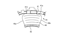
図9は、実施例1における上インシュレータ24のインシュレータティース部42に、ノズルNによって巻き線46を巻回する状態を示す平面図である。図10は、図9におけるノズルNの先端の軌跡を拡大して示す平面図である。図11は、実施例1における上インシュレータ24のインシュレータティース部42に巻き線46が巻回された状態を示す平面図である。巻線機には、まず、上インシュレータ24及び下インシュレータ25と、図示しない絶縁フィルムが適切に取り付けられたステータコア23がセットされる。
図9は、実施例1における上インシュレータ24のインシュレータティース部42に、ノズルNによって巻き線46を巻回する状態を示す平面図である。図10は、図9におけるノズルNの先端の軌跡を拡大して示す平面図である。図11は、実施例1における上インシュレータ24のインシュレータティース部42に巻き線46が巻回された状態を示す平面図である。巻線機には、まず、上インシュレータ24及び下インシュレータ25と、図示しない絶縁フィルムが適切に取り付けられたステータコア23がセットされる。
図9及び図10に示すように、巻線機のノズルNは、ステータコア23に対して、上インシュレータ24及び下インシュレータ25の径方向の中心側に位置する回転中心Oまわりに回動されると共に、巻き線46を供給するノズルNに対して、巻線機によってステータコア23がステータ22の軸方向に移動される。このようなノズルN及びステータコア23の移動により、上インシュレータ24及び下インシュレータ25の各インシュレータティース部42を介してステータコア23のステータコアティース部32に巻き線46が巻回されることで巻回部45が形成される。
なお、巻線機において、ノズルNは、外周壁部41の径方向に沿って延びており、ノズルNの回転中心Oが、外周壁部41の径方向に沿う直線上に位置している。また、外周壁部41の周方向において、ノズルNの回転中心Oに対して、開口部側外周壁部41Fの中心位置と、インシュレータティース部側外周壁部41Tの中心位置(インシュレータティース部42の中心位置)とがなす回転角度は、それぞれ20[°]程度に設定されている。
巻線機は、上インシュレータ24の外周壁部41の中心側から延ばされたノズルNを、ステータ22の軸方向において鍔部43の上方を越えて通過するように、外周壁部41の中心側に位置する回転中心Oまわりに回動させる。つまり、ノズルNは、鍔部43に接触しないように、外周壁部41の内周面41aの周方向に回動する。このとき、ノズルNは、開口部側外周壁部41Fからインシュレータティース部側外周壁部41Tに向かって、ステータ22の軸方向に直交する平面上に沿って旋回することで、外周壁部41の周方向において、インシュレータティース部42の周方向一端側としての進入端42A側から、インシュレータティース部42の周方向他端側としての退出端42B側に向かって巻き線46を巻き付けるように巻回する。
そして、外周壁部41の周方向において、インシュレータティース部42の進入端42Aにおいて、ノズルNから供給される巻き線46が、外周壁部41の内周面41aに接するようにノズルNがインシュレータティース部42に進入し、インシュレータティース部42の中央で、ノズルNの先端が外周壁部41の内周面41aに接触しないように隙間Gをあけながら旋回し、インシュレータティース部42の退出端42BからノズルNが退出する。
上述したように、外周壁部41の周方向におけるインシュレータティース部42の中央で、ノズルNの先端と内周面41aとの間に隙間Gが確保される。言い換えれば、ノズルNが旋回する際、軸方向から見てインシュレータティース部42に僅かでも重なる位置に移動したときに隙間Gが確保される。これにより、インシュレータティース部42の進入端42A側から旋回するノズルNの先端の位置を、外周壁部41の内周面41a近傍まで到達させて巻き始めることが可能になる。このため、インシュレータティース部42の進入端42Aから巻き線46を巻き始める位置が、外周壁部41の内周面41aに近い位置となる。
その結果、図11に示すように、インシュレータティース部42に巻き線46が巻回された巻回部45は、外周壁部41の内周面41aに近い位置から巻き線46が整列状態で規則正しく巻回された整列巻きにすることが可能になる。このため、外周壁部41の周方向における巻回部45の両端(進入端42A及び退出端42B)の各側面45a、45bが、外周壁部41の径方向に沿う直線状に整列されて、巻回部45を整った扇状に形成することができる。したがって、インシュレータティース部42における巻き線46の占積率が高められる。また、巻回部45が整列巻きになることにより、隣接する巻回部45同士の間にノズルNが通過できる空間を確保できる。したがって、巻き線46の巻回時にノズルNと巻回部45との接触が抑えられるので、接触による巻き線46の絶縁性の低下を防げる。なお、整列巻きとは、巻回部45に積層された各層の巻き線46が、巻き線46の直径の1/2ピッチずつずれて積み重ねられて巻かれることを指す。
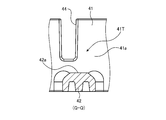
また、実施例1におけるインシュレータティース部42は、巻き線46が巻かれる周面が、ステータ22の軸方向において、外周壁部41の上端側(ステータ22から離れる側)に突出する曲面に形成されている。図12は、実施例1における上インシュレータ24のインシュレータティース部42の形状を示す縦断面図である。図13は、実施例1における上インシュレータ24のインシュレータティース部42の他の形状を示す縦断面図である。図12は、図4、図6におけるQ-Q線に沿う縦断面図である。図13は、インシュレータティース部42の他の形状を、図12と同様に示す縦断面図である。
図12に示すように、インシュレータティース部42の周面42aは、ステータ22の軸方向におけるインシュレータティース部42の厚さが、外周壁部41の周方向におけるインシュレータティース部42の両端(進入端42A及び退出端42B)から中央に向かって大きくなる曲面を有する、いわゆる蒲鉾形状に形成されている。このようにインシュレータティース部42の断面形状を蒲鉾形状に形成することにより、外周壁部41の周方向におけるインシュレータティース部42の中央の厚さを増やして機械的強度を更に高めることが可能になる。これにより、外周壁部41が内側に倒れようとしてもインシュレータティース部42が外周壁部41を支えるので、外周壁部41の径方向の内側に外周壁部41が倒れることを更に防いでいる。
また、インシュレータティース部42において巻き線46が巻かれる周面42aは、外周壁部41の上端側に突出する曲面に限定されず、図13に示すように、平坦面に形成されてもよい。
つぎに、実施例1における上インシュレータ24の巻き線46の巻回状態と比較するために、比較例における上インシュレータを説明する。図14は、比較例における上インシュレータを示す斜視図である。図15は、比較例における上インシュレータのインシュレータティース部に向かってノズルNを回動させる状態を示す平面図である。比較例における上インシュレータにおいても、実施例1における上インシュレータ24と同一部分には同一符号を付して説明を省略する。
図14及び図15に示すように、比較例の上インシュレータ124の外周壁部41は、開口部側外周壁部41Fを有しており、外周壁部41の厚さが、実施例1と同様に、外周壁部41の周方向において開口部側外周壁部41F側から、インシュレータティース部42の中央に近づくに従って大きくなっている。しかし、比較例における上インシュレータ124は、実施例1のように外周壁部41の上端が基端よりも薄くなっておらず、ステータ22の軸方向において外周壁部41の厚さが一定に形成されている。
図16は、比較例における上インシュレータ124のインシュレータティース部42に、ノズルNによって巻き線46を巻回する状態を示す平面図である。図17は、比較例における上インシュレータ124のインシュレータティース部42に巻き線46が巻回された状態を示す平面図である。
図16に示すように、比較例における上インシュレータ124のインシュレータティース部42に巻き線46を巻き付ける場合、外周壁部41の周方向におけるインシュレータティース部42の中央をノズルNが通過するときにノズルNの先端と外周壁部41の内周面41aとの接触を避けるために、ノズルNの先端を、外周壁部41の径方向の中心側に寄せて旋回させる必要がある。このため、外周壁部41の周方向において、ノズルNから供給される巻き線46を、インシュレータティース部42の進入端42Aから巻き始める位置が、鍔部43側に寄った位置となる。
このため、比較例では、ノズルNの先端から供給される巻き線46と外周壁部41の内周面41aとの間に隙間Kが必要になる。これに対して、図10に示す実施例1では、図16に示す比較例のように隙間Kが生じることが抑えられるので、ノズルNから供給される巻き線46をインシュレータティース部42の進入端42Aから巻き始める位置を、外周壁部41の内周面41aに近づけることができる。すなわち、インシュレータティース部42の進入端42Aにおいて、巻き線46を巻き始める位置と、外周壁部41の内周面41aとの間に隙間Kが生じるので、実施例1のように巻き線46を内周面41aに沿って巻き付けることができない。
その結果、図17に示すように、インシュレータティース部42に巻き線46が巻回された巻回部45は、巻き線46が整列巻きにならず、外周壁部41の周方向における巻回部45の両端(進入端42A及び退出端42B)の各側面45a,45bの内周面41a側が、円弧状に湾曲された形状となる。すなわち、比較例では、図11に示す実施例1のように、巻回部45を整った扇状に形成することができないので、巻き線46の占積率の低下を招く。また、比較例における巻回部45は、インシュレータティース部42の中央から外周壁部41の内周面41aに向かって巻き線46が膨らむように巻回される傾向がある。このため、比較例では、巻き線46の巻回時にノズルNと巻回部45とが接触するおそれがあり、接触による巻き線46の絶縁性の低下を招く。
[実施例1の効果]
上述のように実施例1の3相モータ6の上インシュレータ24(下インシュレータ25)において、インシュレータティース部側外周壁部41Tの径方向における厚さは、ステータ22の軸方向においてステータ22に近い基端側よりも、ステータ22側から遠い上端側が小さくなると共に、インシュレータティース部側外周壁部41Tの基端側の厚さt2は、開口部側外周壁部41Fの厚さt1よりも大きい。これにより、外周壁部41の機械的強度を確保して外周壁部41の径方向の内側に外周壁部41が倒れることを防ぎつつ、巻き線46を外周壁部41の内周面41aに沿って巻き始めることでインシュレータティース部42における巻き線46の占積率を向上することができる。また、巻き線46を外周壁部41の内周面41aに沿って巻き始めることで巻き線46を整列巻きにすることが可能となり、インシュレータティース部42における巻き線46の巻回状態の品質を高めることができる。さらに、巻回部45が整列巻きになることにより、巻き線46の巻回時にノズルNと巻回部45との接触が抑えられるので、接触による巻き線46の絶縁性の低下を防ぐことができる。
上述のように実施例1の3相モータ6の上インシュレータ24(下インシュレータ25)において、インシュレータティース部側外周壁部41Tの径方向における厚さは、ステータ22の軸方向においてステータ22に近い基端側よりも、ステータ22側から遠い上端側が小さくなると共に、インシュレータティース部側外周壁部41Tの基端側の厚さt2は、開口部側外周壁部41Fの厚さt1よりも大きい。これにより、外周壁部41の機械的強度を確保して外周壁部41の径方向の内側に外周壁部41が倒れることを防ぎつつ、巻き線46を外周壁部41の内周面41aに沿って巻き始めることでインシュレータティース部42における巻き線46の占積率を向上することができる。また、巻き線46を外周壁部41の内周面41aに沿って巻き始めることで巻き線46を整列巻きにすることが可能となり、インシュレータティース部42における巻き線46の巻回状態の品質を高めることができる。さらに、巻回部45が整列巻きになることにより、巻き線46の巻回時にノズルNと巻回部45との接触が抑えられるので、接触による巻き線46の絶縁性の低下を防ぐことができる。
また、実施例1の3相モータ6の上インシュレータ24(下インシュレータ25)は、外周壁部41の径方向における厚さが、外周壁部41の周方向において開口部側外周壁部41F(開口部側外周壁部41Fの下端の厚さt1)側からインシュレータティース部42の中央(インシュレータティース部側外周壁部41Tの基端の厚さt2)に近づくに従って大きくなる。これにより、インシュレータティース部側外周壁部41Tの厚さが、開口部側外周壁部41Fの厚さよりも厚くなるので、機械的強度が高められ、外周壁部41の径方向の内側に外周壁部41が倒れることを更に防ぐことができる。
また、実施例1の3相モータ6の上インシュレータ24(下インシュレータ25)は、ステータ22の軸方向において、外周壁部41が鍔部43よりも高い。このような外周壁部41を有する構造では、巻き線46の巻回時に、ノズルNの先端が外周壁部41の内周面41aに接触するおそれがあるので、インシュレータティース部側外周壁部41Tの内周面41aとノズルNの先端との間に、隙間Gが確保されている。これにより、外周壁部41の内周面41aとノズルNの先端との接触を避けることができる。
以下、実施例2,3について図面を参照して説明する。実施例2、3において、実施例1と同一の構成部材には、実施例1と同一の符号を付して説明を省略する。実施例2は、上インシュレータ24及び下インシュレータ25のインシュレータティース部側外周壁部41Tの内周面41aの形状が、実施例1におけるインシュレータティース部側外周壁部41Tの内周面41aの形状と異なる。
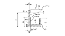
図18は、実施例2における上インシュレータを示す斜視図である。図19は、実施例2における上インシュレータの要部を示す平面図である。図20は、実施例2における上インシュレータの外周壁部41の形状を示す縦断面図である。図20は、図19におけるA2-A2線に沿う縦断面図である。
図18及び図19に示すように、実施例2における上インシュレータ24-2の外周壁部41は、開口部側外周壁部41Fよりも厚さが大きく形成されたインシュレータティース部側外周壁部41T-2を有する。インシュレータティース部側外周壁部41T-2の内周面41aには、ステータ22の軸方向においてステータ22側から遠い上端側に段差部41Taが形成されている。
図20に示すように、インシュレータティース部側外周壁部41T-2は、インシュレータティース部42に連結された基端の厚さがt2に形成されており、ステータ22の軸方向における外周壁部41の高さの途中に段差部41Taが形成されることで外周壁部41の上端側の厚さが薄く形成されている。実施例2においても、開口部側外周壁部41Fの厚さをt1としたとき(図7)、
t1<t2 ・・・(式2)
を満たす。
t1<t2 ・・・(式2)
を満たす。
例えば、インシュレータティース部側外周壁部41T-2の上端の厚さは、図20に示すように、開口部側外周壁部41Fの厚さt1と同様に厚さt1に形成されている。
また、ステータ22の軸方向において、巻き線46の巻回時に外周壁部41の周方向におけるインシュレータティース部42の中央を通過するときのノズルNの下端の高さをh1とし、インシュレータティース部側外周壁部41T-2が有する段差部41Taの高さをh2とし、鍔部43の高さをh3とする。ここで、段差部41Taの高さは、インシュレータティース部側外周壁部41T-2において厚さが薄くなった上端側と段差部41Taとの境界の高さを指す。このとき、インシュレータティース部側外周壁部41T-2が有する段差部41Taは、
h1>h2≧h3 ・・・(式4)
を満たす。
h1>h2≧h3 ・・・(式4)
を満たす。
段差部41Taが形成されたインシュレータティース部側外周壁部41T-2は、式2、4を満たすことにより、図19及び図20に示すように、巻き線46の巻回時に、インシュレータティース部側外周壁部41T-2の周方向におけるインシュレータティース部42の中央を通過するノズルNの先端と、内周面41aとの間に隙間Gが確保されるので、ノズルNと内周面41aとの接触が避けられている。
また、実施例2においても、実施例1と同様に、インシュレータティース部42の進入端42Aから巻き線46を巻き始める位置が、外周壁部41の内周面41aに近い位置となる。このため、インシュレータティース部42に形成される巻回部45は、図11に示すように、巻き線46が規則正しく巻回された整列巻きとなる。
[実施例2の効果]
実施例2における上インシュレータ24-2の外周壁部41には、段差部41Taを有するインシュレータティース部側外周壁部41T-2が形成されることにより、インシュレータティース部側外周壁部41T-2におけるインシュレータティース部42側(ステータ22側)の厚さを厚く形成される部分を増やすことが可能になる。このため、実施例1におけるインシュレータティース部側外周壁部41Tと比べて、インシュレータティース部側外周壁部41T-2の機械的強度を更に高めることができる。したがって、実施例2においても、実施例1と同様に、外周壁部41の径方向の内側に外周壁部41が倒れることを防ぐことができる。
実施例2における上インシュレータ24-2の外周壁部41には、段差部41Taを有するインシュレータティース部側外周壁部41T-2が形成されることにより、インシュレータティース部側外周壁部41T-2におけるインシュレータティース部42側(ステータ22側)の厚さを厚く形成される部分を増やすことが可能になる。このため、実施例1におけるインシュレータティース部側外周壁部41Tと比べて、インシュレータティース部側外周壁部41T-2の機械的強度を更に高めることができる。したがって、実施例2においても、実施例1と同様に、外周壁部41の径方向の内側に外周壁部41が倒れることを防ぐことができる。
また、実施例2においても、実施例1と同様に、巻き線46を外周壁部41の内周面41aに沿って巻き始めることで巻き線46を整列巻きにすることができるので、インシュレータティース部42における巻き線46の巻回状態の品質を高め、かつ、インシュレータティース部42における巻き線46の占積率を向上することができる。また、巻回部45が整列巻きになることにより、巻き線46の巻回時にノズルNと巻回部45との接触が抑えられるので、接触による巻き線46の絶縁性の低下を防ぐことができる。
実施例3は、上インシュレータ24及び下インシュレータ25のインシュレータティース部側外周壁部の内周面41aの形状が、実施例1、2におけるインシュレータティース部側外周壁部41T、41T-2の内周面41aの形状と異なる。
図21は、実施例3における上インシュレータを示す斜視図である。図22及び図23は、実施例3における上インシュレータの外周壁部41の形状を示す縦断面図である。図22は、図21におけるA3-A3線に沿う縦断面図であり、インシュレータティース部42の進入端42A側の縦断面図である。図23は、図21におけるA4-A4線に沿う縦断面図であり、インシュレータティース部42の退出端42B側の縦断面図である。A3-A3線及びA4-A4線は、ノズルNの回転中心Oを通る、上インシュレータの径方向に沿う切断線である。
図21に示すように、実施例3における上インシュレータ24-3の外周壁部41は、インシュレータティース部側外周壁部41T-3を有する。インシュレータティース部側外周壁部41T-3の厚さは、周方向におけるインシュレータティース部42の進入端42A側と退出端42B側とで異なり、インシュレータティース部側外周壁部41T-3において退出端42B側の厚さが、進入端42A側の厚さよりも大きい。図22及び図23に示すように、インシュレータティース部側外周壁部41T-3の内周面41aには、インシュレータティース部側外周壁部41T-3の周方向において、インシュレータティース部42の進入端42A側に第1形状部41TAが形成されると共に、インシュレータティース部42の退出端42B側に第2形状部41TBが形成されている。例えば、第1形状部41TAと第2形状部41TBは、インシュレータティース部側外周壁部41T-3の周方向におけるインシュレータティース部42の中心を通る、外周壁部41の径方向に沿う直線を境界として分かれており、外周壁部41の周方向においてインシュレータティース部側外周壁部41T-3が非対称形状に形成されている。
インシュレータティース部側外周壁部41T-3の第1形状部41TAは、図22に示すように、実施例1におけるインシュレータティース部側外周壁部41Tと同様に形成されており、ステータ22の軸方向に対してステータ22側から離れるに従ってインシュレータティース部側外周壁部41T-3の厚さが徐々に小さくなるように形成されている。すなわち、第1形状部41TAは、上述した式1、2を満たしており、巻き線46の巻回時に、インシュレータティース部側外周壁部41T-3の周方向におけるインシュレータティース部42の中央を通過するノズルNの先端と、第1形状部41TAの内周面41aとの間に隙間Gが確保されることで、ノズルNと内周面41aとの接触が避けられている。
インシュレータティース部側外周壁部41T-3の第2形状部41TBは、図23に示すように、実施例2におけるインシュレータティース部側外周壁部41T-2と同様に形成されており、ステータ22の軸方向に対してステータ22側から遠い側に段差部41Taを有している。すなわち、第2形状部41TBは、上述した式2、4を満たしており、巻き線46の巻回時に、インシュレータティース部側外周壁部41T-2の周方向におけるインシュレータティース部42の中央を通過するノズルNの先端と、第2形状部41TBの内周面41aとの間に隙間Gが確保されることで、ノズルNと内周面41aとの接触が避けられている。
巻き線46の巻回時に、外周壁部41の周方向におけるインシュレータティース部42の中央をノズルNが通過した後、外周壁部41の内周面41aに対して旋回するノズルNの先端が、内周面41aから遠ざかるように回動するので、インシュレータティース部42の退出端42B側における外周壁部41の厚さを増やす余地がある。このため、実施例3におけるインシュレータティース部側外周壁部41T-3は、インシュレータティース部42の進入端31A側に第1形状部41TAが形成され、かつ、インシュレータティース部42の退出端42B側に、第1形状部41TAと比べてインシュレータティース部側外周壁部41T-3の厚さを増やすことが可能な第2形状部41TBが形成されることにより、退出端42B側におけるインシュレータティース部側外周壁部41T-3の厚さを増やして、インシュレータティース部側外周壁部41T-3の機械的強度の低下を抑えることができる。
また、実施例3においても、実施例1、2と同様に、インシュレータティース部42の進入端42Aから巻き線46を巻き始める位置が、外周壁部41の内周面41aに近い位置となる。このため、インシュレータティース部42に形成される巻回部45は、図11に示すように、巻き線46が規則正しく巻回された整列巻きとなる。
[実施例3の効果]
実施例3における上インシュレータ24-3のインシュレータティース部側外周壁部41T-3の厚さは、周方向におけるインシュレータティース部42の進入端42A側と退出端42B側とで異なり、インシュレータティース部側外周壁部41T-3において退出端42B側の厚さが、進入端42A側の厚さよりも大きい。つまり、インシュレータティース部側外周壁部41T-3は、第1形状部41TAと第2形状部41TBを有することにより、インシュレータティース部側外周壁部41T-3における退出端42B側の厚さを進入端42A側の厚さよりも増やすことが可能になるので、実施例1におけるインシュレータティース部側外周壁部41Tと比べて、インシュレータティース部側外周壁部41T-3の機械的強度を更に高めることができる。したがって、実施例3においても、実施例1と同様に、外周壁部41の径方向の内側に外周壁部41が倒れることを防ぐことができる。
実施例3における上インシュレータ24-3のインシュレータティース部側外周壁部41T-3の厚さは、周方向におけるインシュレータティース部42の進入端42A側と退出端42B側とで異なり、インシュレータティース部側外周壁部41T-3において退出端42B側の厚さが、進入端42A側の厚さよりも大きい。つまり、インシュレータティース部側外周壁部41T-3は、第1形状部41TAと第2形状部41TBを有することにより、インシュレータティース部側外周壁部41T-3における退出端42B側の厚さを進入端42A側の厚さよりも増やすことが可能になるので、実施例1におけるインシュレータティース部側外周壁部41Tと比べて、インシュレータティース部側外周壁部41T-3の機械的強度を更に高めることができる。したがって、実施例3においても、実施例1と同様に、外周壁部41の径方向の内側に外周壁部41が倒れることを防ぐことができる。
また、実施例3においても、実施例1、2と同様に、巻き線46を外周壁部41の内周面41aに沿って巻き始めることで巻き線46を整列巻きにすることができるので、インシュレータティース部42における巻き線46の巻回状態の品質を高め、かつ、インシュレータティース部42における巻き線46の占積率を向上することができる。また、巻回部45が整列巻きになることにより、巻き線46の巻回時にノズルNと巻回部45との接触が抑えられるので、接触による巻き線46の絶縁性の低下を防ぐことができる。
なお、本実施例では、3相モータがロータリ圧縮機に適用されたが、ロータリ圧縮機に限定されず、スクロール圧縮機に適用されてもよい。
1 圧縮機
3 シャフト
5 圧縮部
6 3相モータ
21 ロータ
22 ステータ
24 上インシュレータ(インシュレータ)
25 下インシュレータ(インシュレータ)
41 外周壁部
41a 内周面
41b 外周面
41F 開口部側外周壁部
41T インシュレータティース部側外周壁部(巻胴部側外周壁部)
41Ta 段差部
41TA 第1形状部
41TB 第2形状部
42(42-1~42-9) インシュレータティース部(巻胴部)
43(43-1~43-9) 鍔部(内周壁部)
42a 周面
42A 進入端(周方向一端)
42B 退出端(周方向他端)
45 巻回部
46(46-U1~46-U3) 複数のU相巻き線
46(46-V1~46-V3) 複数のV相巻き線
46(46-W1~46-W3) 複数のW相巻き線
47(47-1~47-9) 開口部
G 隙間
N ノズル
3 シャフト
5 圧縮部
6 3相モータ
21 ロータ
22 ステータ
24 上インシュレータ(インシュレータ)
25 下インシュレータ(インシュレータ)
41 外周壁部
41a 内周面
41b 外周面
41F 開口部側外周壁部
41T インシュレータティース部側外周壁部(巻胴部側外周壁部)
41Ta 段差部
41TA 第1形状部
41TB 第2形状部
42(42-1~42-9) インシュレータティース部(巻胴部)
43(43-1~43-9) 鍔部(内周壁部)
42a 周面
42A 進入端(周方向一端)
42B 退出端(周方向他端)
45 巻回部
46(46-U1~46-U3) 複数のU相巻き線
46(46-V1~46-V3) 複数のV相巻き線
46(46-W1~46-W3) 複数のW相巻き線
47(47-1~47-9) 開口部
G 隙間
N ノズル
Claims (11)
- ロータと、前記ロータを回転させる磁界を発生するステータと、前記ステータの軸方向の端部に固定される筒状のインシュレータと、前記インシュレータを介して前記ステータに巻回される巻き線と、を備え、
前記インシュレータは、筒状の外周壁部と、前記外周壁部の内周面に一端部が連結されて前記一端部から前記外周壁部の径方向に延びる複数の巻胴部と、前記巻胴部の他端部から前記ステータの軸方向に向かって棒状に突出して形成された複数の内周壁部と、周方向に隣接する前記内周壁部の間に形成された開口部と、を有し、
前記外周壁部において、前記巻胴部の外径側を巻胴部側外周壁部とし、前記開口部の外径側を開口部側外周壁部としたとき、
前記巻胴部側外周壁部の径方向における厚さは、前記ステータの軸方向において前記ステータに近い基端側よりも、前記ステータ側から遠い先端側が小さくなると共に、前記巻胴部側外周壁部の基端側の厚さは、前記開口部側外周壁部の厚さよりも大きい、モータ。 - 前記外周壁部の前記厚さは、前記外周壁部の周方向において前記開口部側外周壁部側から前記巻胴部の中央に近づくに従って大きくなる、
請求項1に記載のモータ。 - 前記ステータの軸方向において、前記外周壁部は、前記内周壁部よりも高い、
請求項1に記載のモータ。 - 前記巻胴部側外周壁部の前記厚さは、前記巻胴部の周方向一端側と周方向他端側とで異なり、前記周方向他端側での前記厚さが前記周方向一端側での前記厚さよりも大きい、
請求項1に記載のモータ。 - 前記巻胴部側外周壁部の前記厚さは、前記ステータの軸方向において前記ステータ側から離れるに従って徐々に小さくなる、
請求項1に記載のモータ。 - 前記巻胴部側外周壁部の内周面には、前記ステータの軸方向において前記ステータ側から遠い側に段差部が形成される、
請求項1に記載のモータ。 - 前記巻胴部側外周壁部の内周面には、前記巻胴部の周方向一端側に、前記ステータの軸方向に対して前記ステータ側から離れるに従って前記巻胴部側外周壁部の前記厚さが徐々に小さくなる第1形状部が形成され、周方向他端側に、前記ステータの軸方向に対して前記ステータ側から遠い側に段差部を有する第2形状部が形成される、
請求項1に記載のモータ。 - 前記巻胴部において、前記巻き線が巻かれる周面は、前記ステータの軸方向における前記巻胴部の厚さが、前記外周壁部の周方向における前記巻胴部の両端から中央に向かって大きくなる曲面を有する、
請求項1に記載のモータ。 - 請求項1に記載のモータと、
前記ロータが回転軸を回転させることで冷媒を圧縮する圧縮部と、
を備える圧縮機。 - ロータと、前記ロータを回転させる磁界を発生するステータと、前記ステータの軸方向の端面に固定される筒状のインシュレータと、前記インシュレータを介して前記ステータに巻回される巻き線と、を備えるモータの製造方法であって、
筒状の外周壁部と、前記外周壁部の内周面に一端部が連結されて前記一端部から前記外周壁部の径方向に向かって棒状に延びる複数の巻胴部と、前記巻胴部の他端部から前記ステータの軸方向に突出して形成された複数の内周壁部と、周方向に隣接する前記内周壁部の間に形成された開口部と、を有し、前記外周壁部において、前記巻胴部の外径側を巻胴部側外周壁部とし、前記開口部の外径側を開口部側外周壁部としたとき、前記巻胴部側外周壁部の径方向における厚さは、前記ステータの軸方向において前記ステータに近い基端側よりも、前記ステータ側から遠い先端側が小さくなると共に、前記巻胴部側外周壁部の基端側の厚さは、前記開口部側外周壁部の厚さよりも大きい前記インシュレータを用いて、
前記巻き線を供給するノズルを、前記インシュレータの径方向の中心側から延ばして、前記ステータの軸方向において前記内周壁部を越えて通過するように、前記外周壁部の周方向に回動させることによって、前記巻胴部の周方向一端側から周方向他端側に向かって前記巻き線を巻回する、モータの製造方法。 - 前記巻胴部側外周壁部の内周面において、前記周方向一端側に、前記ステータの軸方向に対して前記ステータ側から離れるに従って前記巻胴部側外周壁部の前記厚さが徐々に小さくなる第1形状部が形成され、前記周方向他端側に、前記ステータの軸方向に対して前記ステータ側から遠い側に段差部を有する第2形状部が形成された前記インシュレータを用いて、
前記周方向一端側から前記ノズルの先端を進入させ、前記周方向他端側から前記ノズルの先端を退出させる、
請求項10に記載のモータの製造方法。
Priority Applications (2)
| Application Number | Priority Date | Filing Date | Title |
|---|---|---|---|
| US17/619,078 US12021429B2 (en) | 2019-06-27 | 2020-06-10 | Motor, compressor, and motor manufacturing method |
| CN202080043777.XA CN114008895B (zh) | 2019-06-27 | 2020-06-10 | 电动机、压缩机及电动机的制造方法 |
Applications Claiming Priority (2)
| Application Number | Priority Date | Filing Date | Title |
|---|---|---|---|
| JP2019120372A JP6773182B1 (ja) | 2019-06-27 | 2019-06-27 | モータ、圧縮機及びモータの製造方法 |
| JP2019-120372 | 2019-06-27 |
Publications (1)
| Publication Number | Publication Date |
|---|---|
| WO2020261998A1 true WO2020261998A1 (ja) | 2020-12-30 |
Family
ID=72829295
Family Applications (1)
| Application Number | Title | Priority Date | Filing Date |
|---|---|---|---|
| PCT/JP2020/022887 Ceased WO2020261998A1 (ja) | 2019-06-27 | 2020-06-10 | モータ、圧縮機及びモータの製造方法 |
Country Status (4)
| Country | Link |
|---|---|
| US (1) | US12021429B2 (ja) |
| JP (1) | JP6773182B1 (ja) |
| CN (1) | CN114008895B (ja) |
| WO (1) | WO2020261998A1 (ja) |
Families Citing this family (1)
| Publication number | Priority date | Publication date | Assignee | Title |
|---|---|---|---|---|
| JP7314968B2 (ja) * | 2021-03-22 | 2023-07-26 | 株式会社富士通ゼネラル | 電動機、および圧縮機 |
Citations (3)
| Publication number | Priority date | Publication date | Assignee | Title |
|---|---|---|---|---|
| JPH11150900A (ja) * | 1997-09-12 | 1999-06-02 | Toshiba Corp | 電動機 |
| JP2013138585A (ja) * | 2011-12-28 | 2013-07-11 | Fujitsu General Ltd | 電動機 |
| JP2018137926A (ja) * | 2017-02-22 | 2018-08-30 | アイチエレック株式会社 | 端部絶縁部材、固定子および回転機 |
Family Cites Families (5)
| Publication number | Priority date | Publication date | Assignee | Title |
|---|---|---|---|---|
| KR100934661B1 (ko) | 2007-12-18 | 2009-12-31 | 엘지전자 주식회사 | 모터 |
| JP5862145B2 (ja) | 2011-09-19 | 2016-02-16 | 日本電産株式会社 | モータおよびモータの製造方法 |
| JP5110212B1 (ja) * | 2012-01-31 | 2012-12-26 | 株式会社富士通ゼネラル | 電動機 |
| US20130200742A1 (en) * | 2012-02-08 | 2013-08-08 | Asmo Co., Ltd. | Stator, brushless motor, stator manufacturing method |
| JP5726277B1 (ja) * | 2013-11-29 | 2015-05-27 | 三菱電機株式会社 | 回転電機、回転電機の固定子、及び回転電機の固定子の製造方法 |
-
2019
- 2019-06-27 JP JP2019120372A patent/JP6773182B1/ja active Active
-
2020
- 2020-06-10 WO PCT/JP2020/022887 patent/WO2020261998A1/ja not_active Ceased
- 2020-06-10 CN CN202080043777.XA patent/CN114008895B/zh active Active
- 2020-06-10 US US17/619,078 patent/US12021429B2/en active Active
Patent Citations (3)
| Publication number | Priority date | Publication date | Assignee | Title |
|---|---|---|---|---|
| JPH11150900A (ja) * | 1997-09-12 | 1999-06-02 | Toshiba Corp | 電動機 |
| JP2013138585A (ja) * | 2011-12-28 | 2013-07-11 | Fujitsu General Ltd | 電動機 |
| JP2018137926A (ja) * | 2017-02-22 | 2018-08-30 | アイチエレック株式会社 | 端部絶縁部材、固定子および回転機 |
Also Published As
| Publication number | Publication date |
|---|---|
| CN114008895A (zh) | 2022-02-01 |
| US12021429B2 (en) | 2024-06-25 |
| JP2021005992A (ja) | 2021-01-14 |
| US20220263374A1 (en) | 2022-08-18 |
| CN114008895B (zh) | 2024-08-09 |
| JP6773182B1 (ja) | 2020-10-21 |
Similar Documents
| Publication | Publication Date | Title |
|---|---|---|
| US12431754B2 (en) | Insulator and motor | |
| US20130315759A1 (en) | Electric motor and fuel pump using the same | |
| JP7326770B2 (ja) | モータ及び圧縮機 | |
| JP6729651B2 (ja) | モータ及び圧縮機 | |
| US10700566B2 (en) | Electric motor and compressor provided with the same | |
| JP7314968B2 (ja) | 電動機、および圧縮機 | |
| US8405274B2 (en) | Motor stator and phase coil preform | |
| US20200212749A1 (en) | Stator of electric rotating machine, hairpin of stator of electric rotating machine and manufacturing method thereof | |
| JP6773182B1 (ja) | モータ、圧縮機及びモータの製造方法 | |
| JP2020072579A (ja) | 圧縮機 | |
| JP4957614B2 (ja) | ステータ、モータおよび圧縮機 | |
| JP6094565B2 (ja) | ステータおよびモータ | |
| JP2022115440A (ja) | 電動機及び圧縮機 | |
| WO2023171372A1 (ja) | 3相モータの製造方法及び3相モータ | |
| JP2004282858A (ja) | 固定子及びそれを用いた回転機 | |
| JP7217215B2 (ja) | インシュレータボビン並びにこれを備える電動機及び機器 | |
| JP5211713B2 (ja) | ステータ、モータおよび圧縮機 | |
| JP7622882B1 (ja) | モータおよび圧縮機 | |
| JP7279301B2 (ja) | 3相モータおよび圧縮機 | |
| JP7143606B2 (ja) | 3相モータおよび圧縮機 | |
| JP6444084B2 (ja) | 回転機 |
Legal Events
| Date | Code | Title | Description |
|---|---|---|---|
| 121 | Ep: the epo has been informed by wipo that ep was designated in this application |
Ref document number: 20831877 Country of ref document: EP Kind code of ref document: A1 |
|
| NENP | Non-entry into the national phase |
Ref country code: DE |
|
| 122 | Ep: pct application non-entry in european phase |
Ref document number: 20831877 Country of ref document: EP Kind code of ref document: A1 |