WO2020261900A1 - ゲルの製造方法、及びゲルの製造装置 - Google Patents
ゲルの製造方法、及びゲルの製造装置 Download PDFInfo
- Publication number
- WO2020261900A1 WO2020261900A1 PCT/JP2020/021843 JP2020021843W WO2020261900A1 WO 2020261900 A1 WO2020261900 A1 WO 2020261900A1 JP 2020021843 W JP2020021843 W JP 2020021843W WO 2020261900 A1 WO2020261900 A1 WO 2020261900A1
- Authority
- WO
- WIPO (PCT)
- Prior art keywords
- raw material
- gel
- material liquid
- liquid
- ribbon
- Prior art date
- Legal status (The legal status is an assumption and is not a legal conclusion. Google has not performed a legal analysis and makes no representation as to the accuracy of the status listed.)
- Ceased
Links
Images





Classifications
-
- B—PERFORMING OPERATIONS; TRANSPORTING
- B01—PHYSICAL OR CHEMICAL PROCESSES OR APPARATUS IN GENERAL
- B01J—CHEMICAL OR PHYSICAL PROCESSES, e.g. CATALYSIS OR COLLOID CHEMISTRY; THEIR RELEVANT APPARATUS
- B01J13/00—Colloid chemistry, e.g. the production of colloidal materials or their solutions, not otherwise provided for; Making microcapsules or microballoons
-
- B—PERFORMING OPERATIONS; TRANSPORTING
- B29—WORKING OF PLASTICS; WORKING OF SUBSTANCES IN A PLASTIC STATE IN GENERAL
- B29C—SHAPING OR JOINING OF PLASTICS; SHAPING OF MATERIAL IN A PLASTIC STATE, NOT OTHERWISE PROVIDED FOR; AFTER-TREATMENT OF THE SHAPED PRODUCTS, e.g. REPAIRING
- B29C41/00—Shaping by coating a mould, core or other substrate, i.e. by depositing material and stripping-off the shaped article; Apparatus therefor
- B29C41/24—Shaping by coating a mould, core or other substrate, i.e. by depositing material and stripping-off the shaped article; Apparatus therefor for making articles of indefinite length
-
- B—PERFORMING OPERATIONS; TRANSPORTING
- B29—WORKING OF PLASTICS; WORKING OF SUBSTANCES IN A PLASTIC STATE IN GENERAL
- B29C—SHAPING OR JOINING OF PLASTICS; SHAPING OF MATERIAL IN A PLASTIC STATE, NOT OTHERWISE PROVIDED FOR; AFTER-TREATMENT OF THE SHAPED PRODUCTS, e.g. REPAIRING
- B29C41/00—Shaping by coating a mould, core or other substrate, i.e. by depositing material and stripping-off the shaped article; Apparatus therefor
- B29C41/34—Component parts, details or accessories; Auxiliary operations
- B29C41/36—Feeding the material on to the mould, core or other substrate
-
- C—CHEMISTRY; METALLURGY
- C08—ORGANIC MACROMOLECULAR COMPOUNDS; THEIR PREPARATION OR CHEMICAL WORKING-UP; COMPOSITIONS BASED THEREON
- C08J—WORKING-UP; GENERAL PROCESSES OF COMPOUNDING; AFTER-TREATMENT NOT COVERED BY SUBCLASSES C08B, C08C, C08F, C08G or C08H
- C08J5/00—Manufacture of articles or shaped materials containing macromolecular substances
- C08J5/18—Manufacture of films or sheets
-
- C—CHEMISTRY; METALLURGY
- C08—ORGANIC MACROMOLECULAR COMPOUNDS; THEIR PREPARATION OR CHEMICAL WORKING-UP; COMPOSITIONS BASED THEREON
- C08J—WORKING-UP; GENERAL PROCESSES OF COMPOUNDING; AFTER-TREATMENT NOT COVERED BY SUBCLASSES C08B, C08C, C08F, C08G or C08H
- C08J9/00—Working-up of macromolecular substances to porous or cellular articles or materials; After-treatment thereof
- C08J9/28—Working-up of macromolecular substances to porous or cellular articles or materials; After-treatment thereof by elimination of a liquid phase from a macromolecular composition or article, e.g. drying of coagulum
Definitions
- the present disclosure relates to a gel manufacturing method and a gel manufacturing apparatus.
- Patent Document 1 discloses a method for continuously producing a wet gel. According to this method, while continuously pouring the second liquid material onto the first liquid layer, the second liquid material formed on the first liquid layer is formed with the second liquid material. It is continuously moved on the first liquid layer so as to move away from the pouring position. The second liquid layer is continuously gelled while the second liquid layer is continuously moved on the first liquid layer, and the formed wet gel is continuously transferred from above the first liquid layer. Extract.
- the viscosity of the raw material liquid is low near the position where the raw material liquid is poured, and the raw material liquid tends to spread not only in the flow direction but also in the width direction. If the raw material liquid spreads too much in the width direction, the raw material liquid adheres to the side wall of the accommodating portion accommodating the liquid layer. The attached raw material liquid gels, and the gel accumulates on the side wall, obstructing the flow of the raw material liquid.
- One aspect of the present disclosure provides a technique capable of stabilizing the flow of the raw material liquid on a liquid layer having a higher density than the raw material liquid of the gel.
- a gel raw material liquid is contained in an accommodating portion and is continuously supplied to the liquid surface of a liquid layer having a higher density than the raw material liquid.
- a flow of the raw material liquid is formed on the liquid surface, an accompanying tape in contact with the widthwise end of the flow of the raw material liquid is accompanied by the flow of the raw material liquid, and the raw material liquid is formed into a ribbon shape and gelled.
- the gelled ribbon-shaped gel is continuously taken out from above the liquid surface.
- the raw material liquid is continuously placed on a storage portion for accommodating a liquid layer having a higher density than the raw material liquid of the gel and the liquid surface of the liquid layer.
- a companion tape that is in contact with the raw material liquid supply unit to be supplied to the liquid surface, the widthwise end of the flow of the raw material liquid formed on the liquid surface, and accompanies the flow of the raw material liquid, and a guide that guides the companion tape. It has a portion and a take-out portion for continuously taking out the ribbon-shaped gel obtained by molding the raw material liquid into a ribbon shape on the liquid surface and gelling the raw material liquid from the accommodating portion.
- the accompanying tape and the guide portion are a pair that are in contact with both ends in the width direction of the flow of the raw material liquid, respectively.
- the distance between the pair of accompanying tapes increases from the upstream side to the downstream side of the flow of the raw material liquid at least in a part above the liquid level. Become.
- the flow of the raw material liquid can be stabilized on a liquid layer having a higher density than the raw material liquid of the gel.
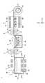
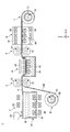
- FIG. 1 is a cross-sectional view showing a gel manufacturing apparatus according to an embodiment.
- FIG. 2 is a flowchart showing a method for producing a gel according to an embodiment.
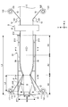
- FIG. 3 is a plan view showing a housing portion according to an embodiment.
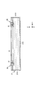
- FIG. 4 is a cross-sectional view taken along the line IV-IV of FIG. 3, which is a cross-sectional view showing an example of a pair of guide plates.
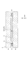
- FIG. 5 is a cross-sectional view taken along the line VV of FIG. 3, which is a cross-sectional view showing an example of the accompanying tape and the guide portion.
- FIG. 6A is a diagram showing an example of force balance when the thickness of the raw material liquid is the equilibrium thickness.
- FIG. 6A is a diagram showing an example of force balance when the thickness of the raw material liquid is the equilibrium thickness.
- FIG. 6B is a diagram showing an example of force balance when the thickness of the raw material liquid is thinner than the equilibrium thickness.
- FIG. 7 is a diagram showing a modified example of the accompanying tape shown in FIG.
- FIG. 8 is a cross-sectional view showing an example of the accompanying tape and gel when passing through the take-out portion.
- FIG. 9 is a plan view showing a modified example of the tape supply portion and the tape peeling portion shown in FIG.
- FIG. 10 is a cross-sectional view showing a manufacturing apparatus according to a modified example.
- FIG. 11 is a cross-sectional view showing an example of a recovery unit adjacent to the storage unit shown in FIGS. 1 and 10.
- Gel includes both “wet gel” and “xerogel”.
- Weight gel means a gel in which the three-dimensional network is swollen by a swelling agent. It includes hydrogels in which the swelling agent is water, alcohol gels in which the swelling agent is alcohol, and organogels in which the swelling agent is an organic solvent.
- Xerogel is a technical term for the structure and process of sol, gel, mesh, and inorganic-organic composite materials of the "International Union of Pure and Applied Chemistry (IUPAC) Inorganic Chemistry Subcommittee and Polymer Subcommittee, Polymer Terminology Subcommittee”. According to the definition (IUPAC Recommendation 2007), it means “a gel consisting of an open network formed by removing a swelling agent from a gel.” There is also a classification method in which the swelling agent is removed by supercritical drying as airgel, the swelling agent removed by normal evaporation drying as xerogel, and the swelling agent removed by freeze-drying as cryogel. In the scope of claims, these are collectively referred to as xerogel.
- “Surface tension” is the force acting on the boundary between a liquid or solid and a gas (for example, air).
- the X-axis direction, Y-axis direction, and Z-axis direction are perpendicular to each other.
- the X-axis direction and the Y-axis direction are horizontal directions, and the Z-axis direction is a vertical direction.
- FIG. 1 is a cross-sectional view showing a gel manufacturing apparatus according to an embodiment.
- the gel manufacturing apparatus 1 includes a molding section 2, a take-out section 3, a solvent replacement section 4, a relay section 5, a drying section 6, and a winding section 7.
- the molding unit 2 molds the raw material liquid A of the gel C into a ribbon shape and gels it.
- the ribbon shape is a sheet shape.
- the take-out part 3 takes out the ribbon-shaped gel C from the molding part 2.
- the solvent replacement unit 4 replaces the solvent contained inside the gel C with another solvent.
- the relay unit 5 conveys the gel C from the solvent replacement unit 4 to the drying unit 6.
- the drying unit 6 removes the solvent contained inside the gel C.
- the winding unit 7 winds the gel C that has passed through the drying unit 6 in a roll shape.
- the manufacturing apparatus 1 Since the manufacturing apparatus 1 is in-lined and a series of processes are carried out all at once, the ribbon-shaped gel C can be efficiently manufactured.
- the molding section 2, the taking-out section 3, the solvent replacing section 4, the relay section 5, the drying section 6, and the winding section 7 are arranged in this order along the passage of the ribbon-shaped gel C.
- the ribbon-shaped gel C continuously continues from the molding portion 2 to the winding portion 7. Since the gel C continues uninterrupted, there is no need to move the gel C extra between steps, and no extra operation or work is required. Therefore, it is possible to prevent unintended deformation when the gel C is moved excessively between steps, and it is possible to prevent the gel C from cracking.
- the gel C of the present embodiment continuously continues from the molding portion 2 to the winding portion 7, but the technique of the present disclosure is not limited to this.
- the gel C does not have to reach the winding section 7 by continuing from the molding section 2 to the drying section 6.
- the gel C does not have to reach the drying portion 6 by continuing from the molding portion 2 to the solvent substitution portion 4.
- it is a continuous type, it is possible to suppress the gel C from cracking.
- the manufacturing apparatus 1 may be installed in a clean room in order to suppress the mixing of foreign substances into the gel C.
- the molding unit 2 includes a storage unit 21 that houses a liquid layer B having a higher density than the raw material liquid A of the gel C, and a raw material liquid supply unit 22 that continuously supplies the raw material liquid A on the liquid surface of the liquid layer B. And have. Since the liquid layer B has a higher density than the raw material liquid A, the layer of the raw material liquid A can be stably formed on the liquid layer B.
- the raw material liquid A flows in a predetermined direction on the liquid surface of the liquid layer B, is formed into a ribbon shape, and is gelled. As a result, a ribbon-shaped gel C is obtained.
- the liquid level of the liquid layer B is naturally leveled by gravity, a flat and uniform gel C can be easily obtained by using the horizontal liquid level. Further, since the liquid surface of the liquid layer B flows according to the expansion, contraction and removal of the gel C, the stress applied to the gel C is small and the defects of the gel C are small. Further, since the entire lower surface of the gel C is supported horizontally, the area of the gel C can be increased.
- the gel C obtained in the molding unit 2 is a wet gel containing a solvent as a swelling agent.
- the thickness of the wet gel is, for example, 0.1 mm to 20 mm, preferably 0.5 mm to 10 mm.
- the wet gel is dried in the drying section 6 to become a xerogel.
- the thickness of the xerogel is, for example, 0.1 mm to 20 mm, preferably 0.5 mm to 10 mm.
- the xerogel may be a porous monolith having transparency and heat insulating properties. Xerogel having transparency and heat insulating property is used as a transparent heat insulating material in, for example, window glass for automobiles and window glass for buildings.
- the transmittance of xerogel at a wavelength of 500 nm is preferably 70% or more, preferably 80% or more, and preferably 90% or more in terms of thickness of 1 mm.
- the transmittance is measured in accordance with the Japanese Industrial Standards (JIS R 3106: 1998).
- xerogel examples include filters, adsorbents, sound absorbing materials, moisture absorbing materials, oil absorbing materials, and separation membranes, in addition to heat insulating materials.
- Xerogel may not be transparent or may be opaque depending on the application.
- xerogel The type of xerogel is (1) polysiloxane xerogel in the present embodiment, but may be (2) polymer xerogel or (3) polysaccharide xerogel such as cellulose xerogel.
- the raw material liquid A contains, for example, a raw material for gel C (hereinafter, also referred to as “gel raw material”) and a solvent for dissolving the gel raw material.
- the gel raw material is appropriately selected according to the type of xerogel finally obtained.
- the solvent is, for example, water or an organic solvent.
- organic solvent examples include alcohols (methanol, ethanol, isopropyl alcohol, tert-butyl alcohol, benzyl alcohol, etc.), aprotic polar organic solvents (N, N-dimethylformamide, dimethylsulfoxide, N, N-dimethylacetamide, etc.), Examples thereof include ketones (cyclopentanone, cyclohexanone, methylethylketone, methylisobutylketone, acetone, etc.), hydrocarbons (n-hexane, heptane, etc.) and the like.
- alcohols methanol, ethanol, isopropyl alcohol, tert-butyl alcohol, benzyl alcohol, etc.
- aprotic polar organic solvents N, N-dimethylformamide, dimethylsulfoxide, N, N-dimethylacetamide, etc.
- ketones cyclopentanone, cyclohexanone, methylethylketone,
- examples of the gel raw material include those containing (1A) a silane compound and (1B) a catalyst. (1B) The catalyst is for uniformly promoting gelation.
- the gel raw material may further contain (1C) a surfactant.
- silane compound examples include alkoxysilane, a 6-membered ring-containing silane compound having a 6-membered ring-containing skeleton and a hydrolyzable silyl group, and a silyl group-containing polymer having an organic polymer skeleton and a hydrolyzable silyl group. Can be mentioned.
- alkoxysilane examples include tetraalkoxysilane (tetramethoxysilane, tetraethoxysilane, etc.), monoalkyltrialkoxysilane (methyltrimethoxysilane, methyltriethoxysilane, etc.), and dialkyldialkoxysilane (dimethyldimethoxysilane, dimethyldiethoxysilane, etc.).
- trimethoxyphenylsilane compounds having alkoxysilyl groups at both ends of the alkylene group (1,6-bis (trimethoxysilyl) hexane, 1,6-bis (methyldimethoxysilyl) hexane, 1,6-bis (Methyldiethoxysilyl) hexane, 1,2-bis (trimethoxysilyl) ethane, 1,2-bis (methyldimethoxysilyl) ethane, 1,2-bis (methyldiethoxysilyl) ethane, etc.), perfluoropolyether Alkoxysilane having a group (perfluoropolyether triethoxysilane, perfluoropolyether methyldiethoxysilane, etc.), alkoxysilane having a perfluoroalkyl group (perfluoroethyltriethoxysilane, etc.), pentafluorophenylethoxydimethylsi
- the 6-membered ring-containing skeleton in the 6-membered ring-containing silane compound is an organic skeleton having at least one 6-membered ring selected from the group consisting of an isocyanul ring, a triazine ring and a benzene ring.
- the organic polymer skeleton of the silyl group-containing polymer is an organic skeleton having at least one chain selected from the group consisting of polyethylene chains, polyether chains, polyester chains and polycarbonate chains.
- Examples of the (1B) catalyst include a base catalyst and an acid catalyst, and an aqueous solution thereof may be used.
- the base catalyst include amines (triethylamine, tetramethylammonium hydroxide, tetraethylammonium hydroxide, etc.), urea, ammonia, sodium hydroxide, potassium hydroxide and the like.
- the acid catalyst include inorganic acids (nitric acid, sulfuric acid, hydrochloric acid, etc.) and organic acids (girate, oxalic acid, acetic acid, monochloroacetic acid, dichloroacetic acid, trichloroacetic acid, monofluoroacetic acid, trifluoroacetic acid, etc.).
- (1C) surfactant examples include hexadecyltrimethylammonium bromide, hexadecyltrimethylammonium chloride, Pluronic F127 (trade name of BASF), EH-208 (trade name of NOF Corporation) and the like.
- the gel raw material includes a thermoplastic resin, a curable resin, and the like.
- thermoplastic resin examples include those capable of dissolving in a solvent when heated and forming a monolith (porous body) when cooled, and specific examples thereof include polymethylmethacrylate and polystyrene.
- Examples of the curable resin include a photocurable resin and a thermosetting resin.
- Examples of the photocurable resin include those containing either one or both of acrylate and methacrylate and a photopolymerization initiator.
- Examples of the thermosetting resin include those containing either one or both of acrylate and methacrylate and a thermal polymerization initiator, an addition condensate of resorcinol and formaldehyde, and an addition condensate of melamine and formaldehyde. Be done.
- examples of the gel raw material include those containing (3A) polysaccharide nanofibers and (3B) acid.
- examples of polysaccharides include chitin, chitosan, and gellan gum in addition to cellulose.
- Examples of the (3A) polysaccharide nanofiber include 2,2,6,6-tetramethylpiperidin-1-oxyl (TEMPO) oxidized cellulose nanofiber.
- Examples of the (3A) polysaccharide nanofiber include chitin nanofiber and chitosan nanofiber in addition to cellulose nanofiber.
- Examples of the (3B) acid include the inorganic acid and the organic acid. Bases can be used instead of acids.
- the liquid layer B preferably has a large density difference from the raw material liquid A so that the layer of the raw material liquid A is stably present on the liquid layer B.
- the density difference is preferably 0.1 g / cm 3 or more, and more preferably 0.5 g / cm 3 or more. From the viewpoint of weight reduction, the density difference is preferably 3.0 g / cm 3 or less, and more preferably 2.0 g / cm 3 or less.
- the liquid layer B is preferably one having low compatibility with the raw material liquid A so that the layer of the raw material liquid A is stably present on the liquid layer B.
- the compatibility between the liquid layer B and the raw material liquid A can be estimated by the upper limit amount of the raw material liquid A dissolved in 100 g of the liquid layer B.
- the upper limit is preferably 100 g or less, more preferably 10 g or less, and even more preferably 1 g or less.
- the upper limit amount is 100 g or less, the separated state of the liquid layer B and the raw material liquid A can be maintained for a long time.
- the lower the upper limit is, the better, and it may be 0 g.
- liquid layer B that does not react with the raw material liquid A in order to allow the layer of the raw material liquid A to stably exist on the liquid layer B. It is preferable that the liquid layer B contains substantially no gel raw material. The fact that the gel raw material is substantially not contained means that the gel raw material other than the gel raw material transferred from the raw material liquid A is not contained.
- the material of the liquid layer B is appropriately selected according to the solvent of the raw material liquid A.
- the material of the liquid layer B include a liquid compound having a fluorine atom, a liquid compound having a chlorine atom, a liquid compound having a silicon atom, water, mercury and the like, and if there is a density difference from the raw material liquid A, fluorine. , Chlorine, bromine, or halogen atoms such as iodine, silicon atoms, etc. need not be contained.
- the water may contain water-soluble salts to adjust the density of the liquid layer B. Examples of the water-soluble salt include sodium chloride and the like.
- liquid compound having a fluorine atom examples include a fluorine-based solvent and a fluorine-based oil.
- Fluorine-based solvents include hydrofluoroalkanes, chlorofluorocarbons, hydrochlorofluorocarbons, hydrofluoromonoethers, perfluoromonoethers, perfluoroalkanes, perfluoropolyethers, perfluoroamines, fluorine atom-containing alkanes, fluorine atom-containing aromatic compounds, and fluorine. Examples thereof include atom-containing ketones and fluorine atom-containing esters.
- fluorine-based oils examples include Solvay's brand name Fomblin and Daikin Industries' brand name Demnum and Daikin Industries.
- liquid compound having a chlorine atom examples include chlorine-based solvents and chlorine-based oils.
- chlorine-based solvent examples include carbon tetrachloride, chloroform, methylene chloride and the like.
- Examples of the liquid compound having a silicon atom include silicone oil and the like.
- Examples of the silicone oil include dimethyl silicone oil and methyl phenyl silicone oil.
- Examples of commercially available silicone oil products include KF-96, which is a trade name of Shin-Etsu Chemical Co., Ltd.
- the gel raw material contains (1A) a silane compound and (1B) a catalyst
- gelation of the raw material liquid A is performed by heating.
- the silane compound is hydrolyzed by an acid catalyst or the like to form a sol having a silanol group (Si—OH).
- the sol is heated, the silanol groups undergo a dehydration condensation reaction between the molecules to form a Si—O—Si bond, and the raw material liquid A is gelled.
- the raw material liquid supply unit 22 includes, for example, a mixing tank for mixing a silane compound and a catalyst.
- the mixing tank may include a cooling device for cooling the raw material liquid A in order to suppress the progress of gelation.
- the temperature of the mixing tank is preferably lower from the viewpoint of suppressing the progress of gelation, but may be set higher than the freezing point of the raw material liquid A from the viewpoint of preventing freezing, and is set to, for example, 0 ° C to 20 ° C.
- the mixing tank may include a stirring device that stirs the raw material liquid A.
- the silane compound and the catalyst can be mixed in a short time, and the raw material liquid A can be homogenized in a short time.
- the mixing tank is connected to the silane compound supply source via the first pipe, and is connected to the catalyst supply source via the second pipe.
- the first pipe is provided with a first flow rate controller that controls the flow rate of the silane compound
- the second pipe is provided with a second flow rate controller that controls the flow rate of the catalyst. Since the flow rate of the silane compound and the flow rate of the catalyst can be controlled, the residence time in the mixing tank can be shortened.
- the flow rate of the silane compound and the flow rate of the catalyst are appropriately determined according to the flow rate of the raw material liquid A supplied onto the liquid layer B.
- the molding unit 2 has a first heater 23, a second heater 24, and a third heater 25 in order to gel the raw material liquid A on the liquid layer B.
- the first heater 23 is arranged above the accommodating portion 21 and heats the raw material liquid A from above.
- the second heater 24 is arranged inside the liquid layer B, and by heating the liquid layer B, the raw material liquid A is heated from below.
- the third heater 25 is arranged below the accommodating portion 21, and heats the liquid layer B to heat the raw material liquid A from below. By heating the raw material liquid A from both the upper and lower sides, gelation can proceed from both the upper and lower sides.
- a plurality of first heaters 23 may be arranged at intervals along the flow direction (X-axis direction) of the raw material liquid A. By independently controlling the plurality of first heaters 23, the temperature distribution in the flow direction of the raw material liquid A can be controlled. The temperature distribution may be uniform over the entire flow direction, may be higher toward the downstream, or may be lower toward the downstream.
- the second heater 24 and the third heater 25 may also be arranged and controlled in the same manner as the first heater 23.
- the heating method of the first heater 23, the second heater 24, and the third heater 25 is not particularly limited, and is, for example, a resistance heating type, an infrared heating type, an arc heating type, or the like, depending on the installation location. Is selected as appropriate.
- the molding unit 2 may have at least one of the first heater 23, the second heater 24, and the third heater 25. Further, although not shown, the heater may be installed so as to heat from the side surface of the liquid layer B. Further, the means for gelling the raw material liquid A is not limited to the heater, and is appropriately selected according to the type of the gel raw material.
- the means for gelling the raw material liquid A is a cooler.
- the cooler cools the raw material liquid A on the liquid layer B and gels the raw material liquid A.
- the cooler may be arranged and controlled in the same manner as the heater. Natural cooling may be performed instead of forced cooling by the cooler.
- the means for gelling the raw material liquid A is a light source.
- the light source irradiates the raw material liquid A existing on the liquid layer B with light such as ultraviolet rays to cure the photocurable monomer and gel the raw material liquid A.
- the light source may be arranged and controlled in the same manner as the heater.
- the means for gelling the raw material liquid A is a heater.
- the gel raw material is a polysaccharide nanofiber
- the polysaccharide nanofiber gels in a short time when it comes into contact with an acid catalyst or a base catalyst. Therefore, the raw material liquid A may contain polysaccharide nanofibers and may not contain an acid catalyst or a base catalyst.
- the acid catalyst or the base catalyst may be supplied in a shower shape from above to the layer of the raw material liquid A formed on the liquid layer B.
- the means for gelling the raw material liquid A is a feeder that supplies an acid catalyst or a base catalyst to the layer of the raw material liquid A from above.
- the take-out unit 3 continuously takes out the ribbon-shaped gel C from above the liquid surface of the liquid layer B.
- the take-out portion 3 is arranged on the downstream side of the accommodating portion 21 and pulls the ribbon-shaped gel C.
- the take-out portion 3 may lift the gel C from the liquid surface immediately before the gel C so as not to hit the downstream wall 212 of the accommodating portion 21.
- Gel C is sufficiently gelled before lifting so that it does not break during lifting.
- the gel C may be slid out by an oblique plate-like body (not shown) provided on the downstream wall 212 of the accommodating portion 21 so that the gel C does not hit the downstream wall 212 of the accommodating portion 21. Since the gel C may be taken out from the accommodating portion 21, the taking-out portion 3 may be inside the accommodating portion 21 or may be outside the accommodating portion 21.
- the equilibrium thickness HA0 is obtained from the following equation (1).
- "g" is the gravitational acceleration, which is 9.8 (m / s 2 ).
- the equilibrium thickness HA0 is determined by the combination of the material of the raw material liquid A and the material of the liquid layer B.
- the thickness HA of the raw material liquid A is the flow rate (supply rate) of the raw material liquid A supplied to the storage unit 21 by the raw material liquid supply unit 22 and the take-out speed of the gel C taken out from the storage unit 21 by the take-out unit 3. Can be controlled. If extraction rate of the gel C is the same, as the feed rate of the raw material liquid A is large, the thickness H A raw material liquid A is increased. Further, when the supply rate of the raw material solution A are the same, the larger the take-out speed of the gel C, thickness H A raw material liquid A is reduced.
- the take-out portion 3 includes, for example, a tension roller 31.
- the tension roller 31 sandwiches the ribbon-shaped gel C from both the upper and lower sides and rotates the gel C to send the gel C to the downstream side.
- An upper tension roller 31 the distance between the tension roller 31 of the lower, so that the thickness H C gel C is not excessively compressed, that is, are set to gel C is not cracked.
- the thickness H C of the gel C is equal to the final thickness H A raw material liquid A.
- the tension roller 31 may not be arranged on both the upper and lower sides of the ribbon-shaped gel C, and may be arranged only on the lower side, for example.
- the tension roller 31 arranged on the lower side rotates while carrying the ribbon-shaped gel C, and sends the gel C to the downstream side.
- the tension roller 31 is made of a metal such as stainless steel, rubber, or a material such as resin.
- the tension roller 31 may be a metal surface coated with rubber, resin, or the like.
- the tension roller 31 may have irregularities on its outer circumference. Due to the unevenness, the slip of the gel C can be suppressed, and the gel C can be reliably sent to the downstream side.
- the solvent replacement unit 4 replaces the solvent contained inside the ribbon-shaped gel C with another solvent.
- Gel C is a fine porous body and contains a solvent inside. The solvent substitution is carried out before drying for the purpose of suppressing the shrinkage of the gel C due to the surface tension of the solvent during drying and suppressing the damage of the fine structure of the gel C.
- the solvent replacement unit 4 replaces the solvent contained inside the gel C with a solvent suitable for gelation (that is, the solvent of the raw material liquid A) with a solvent suitable for drying.
- the solvent after the replacement is appropriately selected depending on the drying method. As the drying method, supercritical drying, freeze drying, or atmospheric drying is used.
- the solvent contained inside the gel C is replaced with a supercritical fluid.
- a solvent suitable for supercritical drying for example, methanol, ethanol, isopropyl alcohol and the like are used.
- the supercritical fluid carbon dioxide gas in a supercritical state is generally used. Supercritical drying is carried out inside a closed high-pressure container.
- freeze-drying the solvent contained inside the gel C is frozen and then evaporated in a vacuum. This is usually called sublimation.
- a solvent suitable for freeze-drying water, tert-butyl alcohol, cyclohexane, 1,4-dioxane, a fluorine-based solvent and the like are used. Freeze-drying is carried out inside a closed vacuum vessel.
- Normal pressure drying evaporates the solvent contained inside the gel C under normal pressure. Since it is important to reduce the contraction force of the fine skeleton of gel C due to the capillary force accompanying solvent evaporation, a solvent suitable for atmospheric drying is a solvent having a small surface tension, for example, a low molecular weight aliphatic such as hexane or heptane. A hydrocarbon solvent or a fluorine solvent is used. Since normal pressure drying is performed at normal pressure, a closed container is not required. Therefore, when the ribbon-shaped gel C continues from the molding portion 2 to the drying portion 6, atmospheric drying is adopted.
- the solvent replacement unit 4 forms a passage through which the ribbon-shaped gel C continuously taken out from the molding unit 2 passes, and replaces the solvent contained inside the gel C with a solvent suitable for atmospheric drying. .. Specifically, the solvent replacement unit 4 replaces the solvent contained inside the gel C with a solvent having a surface tension smaller than that of the raw material liquid A from the solvent of the raw material liquid A.
- Solvent substitution is carried out at a temperature below the boiling point of the solvent in order to prevent the microstructure of the gel from being damaged by boiling of the solvent.
- the solvent may be heated at a temperature below the boiling point.
- the heating temperature is, for example, 40 ° C to 100 ° C.
- the number of times the solvent is replaced is once in this embodiment, but it may be a plurality of times. That is, the solvent contained inside the gel C is replaced with a first solvent different from the solvent of the raw material liquid A from the solvent of the raw material liquid A, and further, a solvent of the raw material liquid A and a second solvent different from the first solvent. May be replaced with.
- the compatibility between the solvent of the raw material liquid A and the second solvent is low, the substitution efficiency becomes poor. Therefore, by temporarily introducing the substitution with the first solvent in the meantime, the solvent of the raw material liquid A can be seconded. The time required for replacement with a solvent can be shortened.
- the first solvent a solvent having high compatibility with both the solvent of the raw material liquid A and the second solvent is used.
- the solvent replacement unit 4 has, for example, a storage tank 41 for storing a solvent in which the ribbon-shaped gel C is immersed.
- a storage tank 41 for storing a solvent in which the ribbon-shaped gel C is immersed.
- a support roller 42 that supports the gel C may be arranged inside the storage tank 41.
- the number of support rollers 42 may be one or more, and in the case of a plurality of support rollers 42, they are arranged at intervals along the passage of the gel C.
- the support roller 42 may be actively rotated by a rotation motor or the like, or may be passively rotated.
- the passage of the gel C does not have a U-shaped folded portion inside the storage tank 41 in the present embodiment, but may have a U-shaped folded portion.
- a support roller 42 is arranged at the folded-back portion, the gel C is curved along the outer circumference of the support roller 42, and the moving direction of the gel C is reversed.
- the liquid overflowing from the storage tank 41 may be collected and recycled. Since the liquid overflowing from the storage tank 41 contains the solvent of the raw material liquid A and the like, it may be purified by means such as distillation before being recycled. By purification, the solvent, catalyst, surfactant and the like of the raw material liquid A can be removed.
- the solvent replacement unit 4 may have a solvent supply unit 43 that supplies a shower-like solvent to the ribbon-shaped gel C from above. Since the shower-like solvent is supplied from above, the immersion depth of the gel C can be made shallow. Since the radius of curvature of the passage of the gel C is large and the bending stress of the gel C is small, it is possible to suppress the gel C from cracking.
- the solvent replacement unit 4 When the solvent replacement unit 4 has the solvent supply unit 43, it does not have to have the storage tank 41. Without the storage tank 41, the passage of gel C can be straightened. Since the bending stress of the gel C becomes zero, it is possible to further suppress the gel C from cracking.
- the solvent replacement is not necessary, so that the manufacturing apparatus 1 does not have to have the solvent replacement part 4.
- the relay unit 5 conveys the ribbon-shaped gel C from the solvent replacement unit 4 to the drying unit 6.
- the speed at which the gel C is conveyed by the relay unit 5 is set so that the gel C passes through the inside of the solvent stored in the storage tank 41, and the gel C flexes downward convexly inside the storage tank 41. Will be done.
- the relay unit 5 includes, for example, a relay roller 51.
- the relay roller 51 is actively rotated by a rotary motor or the like to send the gel C to the downstream side. Since the relay roller 51 is configured in the same manner as the tension roller 31, the description thereof will be omitted.
- the drying unit 6 removes the solvent contained inside the gel C.
- the method for drying the gel C as described above, supercritical drying, freeze drying, or atmospheric drying is used, but in the present embodiment, atmospheric drying suitable for in-line is used.
- the drying portion 6 forms a passage through which the ribbon-shaped gel C continuously taken out from the molding portion 2 passes, and removes the solvent contained in the gel C by atmospheric pressure drying.
- the drying unit 6 has, for example, a drying furnace 61 that forms a passage through which the gel C passes.
- a support roller 62 for supporting the gel C may be arranged inside the drying furnace 61.
- the number of support rollers 62 may be one or more, and in the case of a plurality of support rollers 62, the support rollers 62 are arranged at intervals along the passage of the gel C.
- the support roller 62 may be actively rotated by a rotation motor or the like, or may be passively rotated.
- the passage of the gel C does not have a U-shaped folded portion inside the drying oven 61 in the present embodiment, but may have a U-shaped folded portion.
- a support roller 62 is arranged at the folded-back portion, the gel C is curved along the outer circumference of the support roller 62, and the moving direction of the gel C is reversed.
- the residence time of the gel C inside the drying oven 61 can be lengthened. Further, when the residence time of the gel C inside the drying furnace 61 is the same, the length of the drying furnace 61 can be shortened and the drying furnace 61 can be miniaturized.
- Drying of gel C is carried out at a temperature below the boiling point of the solvent in order to prevent the fine structure of the gel from being damaged by boiling of the solvent.
- the gel C may be heated at a temperature below the boiling point.
- the drying temperature of gel C is, for example, room temperature to 100 ° C.
- the drying unit 6 may have a heater 63 for heating the gel C.
- a plurality of heaters 63 may be arranged on both the upper and lower sides of the gel C passage, and may be arranged at intervals along the gel C passage.
- the heater 63 is arranged inside the drying furnace 61.
- the heating method of the heater 63 is not particularly limited, but is appropriately selected from, for example, a resistance heating type and an infrared heating type, depending on the installation location.
- the drying unit 6 may have a blower (not shown) that blows air to the gel C. By sending wind to the gel C, the evaporation of the solvent contained inside the gel C can be promoted. The solvent evaporated in the drying unit 6 is recovered and discarded or recycled as needed.
- the gel C obtained in the dry portion 6 is a xerogel, which is a porous monolith.
- the winding unit 7 winds the ribbon-shaped gel C that has passed through the drying unit 6 into a roll shape.
- the take-up portion 7 has a take-up roller 71, and the take-up roller 71 is actively rotated by a rotary motor or the like, and a ribbon-shaped gel C is taken up on the outer periphery thereof.
- the outer diameter of the winding roller 71 is set appropriately according to the thickness H C and the material of the gel C, it is set to a gel C is not cracked.
- a take-up core 72 may be detachably attached to the outer circumference of the take-up roller 71, and a ribbon-shaped gel C may be taken up on the outer circumference of the take-up core 72. If the take-up core 72 is used, the roll-shaped gel C can be removed without losing its shape, and the handleability is good.
- the outer circumference of the take-up roller 71 may be provided with irregularities. Due to the unevenness, slippage of the winding core 72 (however, gel C when there is no winding core 72) can be suppressed. Similarly, the outer circumference of the winding core 72 may be provided with irregularities. The unevenness can suppress the slip of the gel C.
- the material of the take-up roller 71 is not particularly limited, but is, for example, metal or resin.
- the resin is excellent in light weight and excellent transportability.
- Non-slip rubber may be attached to the outer circumference of the take-up roller 71.
- the material of the winding core 72 is not particularly limited, but is, for example, metal or resin.
- the resin is excellent in light weight and excellent transportability.
- Non-slip rubber may be attached to the outer circumference of the take-up core 72.
- FIG. 2 is a flowchart showing a method for producing a gel according to an embodiment.
- the method for producing a gel includes molding (S1), solvent substitution (S2), drying (S3), and winding (S4).
- the molding unit 2 performs molding (S1)
- the solvent replacement unit 4 performs solvent substitution (S2)
- the drying unit 6 performs drying (S3)
- the winding unit 7 performs winding (S4). To do.
- the gel production method does not have to include all the treatments shown in FIG. 2.
- the solvent of the raw material liquid A is suitable for drying (S3)
- the solvent replacement (S2) may not be performed.
- the method for producing the gel may include a process different from the process shown in FIG. 2, and may include packing instead of winding (S4), for example. In packing, the ribbon-shaped gel C is cut, and the cut gels are stacked in a packing container.
- FIG. 3 is a plan view showing a housing portion according to an embodiment.
- the accommodating portion 21 is, for example, a rectangular container in a plan view, and has an upstream wall 211, a downstream wall 212, a pair of side walls 213 and 214, and a bottom wall 215 (see FIG. 1). ..
- the length L1 of the accommodating portion 21, that is, the length L1 from the upstream wall 211 to the downstream wall 212 is not particularly limited, but is, for example, 1 m to 100 m from the viewpoint of residence time and productivity.
- a length L1 of the housing portion 21 is constant, if the thickness H C gel C is the same, as the progress of gelation of the raw material liquid A is high, and the retrieval speed of the feed rate and the gel C raw material liquid is greater Therefore, the production volume per unit time is improved.
- the region from the upstream wall 211 to the downstream wall 212 can be distinguished in the flow direction of the raw material liquid A, for example, the first region A1, the second region A2, and the third region A3.
- the first region A1, the second region A2, and the third region A3 are arranged in this order from the upstream side to the downstream side.
- the first region A1 is a region where gelation of the raw material liquid A starts, and is a region where cross-linking starts in a part of the raw material liquid A.
- the raw material liquid A is supplied onto the liquid surface of the liquid layer B in the vicinity of the upstream wall 211 of the first region A1 and flows toward the downstream wall 212.
- the viscosity increases.
- the downstream end of the first region A1 the viscosity of the raw material liquid A is increased to a viscosity suitable for the control of the thickness H A raw material liquid A.
- the viscosity of the raw material liquid A increases to a predetermined viscosity, can be stretched by the raw material solution A tensile stress, it can control the thickness H A raw material liquid A.
- the viscosity suitable for controlling the thickness HA of the raw material liquid A can be obtained by experiments or the like depending on the type of the raw material liquid A.
- the second region A2 is a region in which gelation of the raw material liquid A proceeds, cross-linking proceeds in the entire raw material liquid A, and a three-dimensional skeleton structure of a polymer is formed.
- Control of the thickness H A raw material liquid A is performed in the second region A2.
- the thickness HA of the raw material liquid A is controlled by the balance between the supply speed of the raw material liquid A and the take-out speed of the gel C.
- the downstream end of the second region A2, the viscous flow of the material liquid A is lost, determined is the thickness H A and width W A of the raw material liquid A.
- the width W A of the raw material liquid A similar to the thickness H A raw material liquid A, which is controlled by the balance between the removal rate of the feed rate and the gel C raw material liquid A. Therefore, the control of the thickness H A raw material liquid A, the control of the width W A of the raw material liquid A is the same control.
- the third region A3 is a region in which the gelation of the raw material liquid A further progresses and a finer three-dimensional skeleton structure is formed.
- the third region A3 is a region where the gel C is aged.
- the gel raw material contains (1A) a silane compound and (1B) a catalyst
- the third region A3 is a region where dehydration condensation is completed.
- the gel C is lifted from the liquid surface of the liquid layer B in the vicinity of the downstream wall 212 of the third region A3, and is taken out to the downstream side of the accommodating portion 21.
- the first region A1, the second region A2, and the third region A3 may have the same temperature or different temperatures, but may be lower than the boiling point of the solvent in order to suppress boiling of the solvent. .. It is possible to prevent the three-dimensional skeleton structure of the polymer from being damaged by boiling the solvent.
- the third region A3 may be hotter than the first region A1 and the second region A2. Until determined the thickness H A and width W A of the raw material liquid A is moderately advanced gelation, thereafter, it can proceed rapidly gelling. Therefore, the length L1 of the accommodating portion 21 can be shortened.
- the temperature difference is, for example, 10 ° C to 50 ° C, preferably about 20 ° C.
- the width W1 of the accommodating portion 21, that is, the width W1 of the pair of side walls 213 and 214 is not particularly limited, but is, for example, 1 cm to 10 m.
- FIG. 4 is a cross-sectional view taken along the line IV-IV of FIG. 3, and is a cross-sectional view showing an example of a pair of guide plates.
- the accommodating portion 21 further includes a pair of guide plates 216 and 217, as shown in FIGS. 3 and 4.
- the guide plates 216 and 217 are installed in the first region A1, project downward from the interface between the raw material liquid A and the liquid layer B, and protrude upward from the raw material liquid A.
- the raw material liquid A flows on the liquid surface of the liquid layer B between the pair of guide plates 216 and 217, and then flows between the pair of side walls 213 and 214.
- the viscosity of the raw material liquid A is relatively low between the pair of guide plates 216 and 217, the flow of the raw material liquid A is easily peeled off from the surface of the guide plates 216 and 217, and hardly stays near the surface. Therefore, gel does not accumulate on the surface of the guide plates 216 and 217, and the flow of the raw material liquid A is not clogged.
- the raw material liquid A flows while being in contact with the guide plates 216 and 217, gradually crosslinks, and gradually increases in viscosity.
- the degree of cross-linking of the raw material liquid A is 1% to 50% at the opening at the downstream end of the pair of guide plates 216 and 217.
- the degree of cross-linking represents the degree of progress of the cross-linking reaction, and the degree of cross-linking when all the reaction sites of the cross-linking reaction are cross-linked is 100%.
- the degree of cross-linking is measured by, for example, infrared absorption spectroscopy.
- the viscosity of the raw material liquid A is, for example, 1 Pa ⁇ s to 1000 Pa ⁇ s.
- the viscosity of the raw material liquid A flowing from the pair of guide plates 216, 217 is in an appropriate range, can be stretched by the raw material solution A tensile stress, it can control the thickness H A raw material liquid A.
- the length L2 of the guide plates 216 and 217 in the flow direction of the raw material liquid A is set so that the viscosity of the raw material liquid A becomes an appropriate viscosity. ..
- the opening at the downstream end of the pair of guide plates 216 and 217 may coincide with the boundary between the first region A1 and the second region A2. In the second region A2, the thickness HA of the raw material liquid A is controlled.
- the raw material liquid thickness H A of A thicker than the equilibrium thickness H A0, thus starting solution both ends in the width direction of the flow of A pair of guide plates 216, It touches 217.
- the raw material liquid A spreads in the width direction of the flow of the raw material liquid A as shown in FIG. 3, but does not have to spread.
- the width W1 of the pair of side walls 213 and 214 is wider than the opening width W2 at the downstream end of the pair of guide plates 216 and 217. Therefore, it is possible to prevent the relatively highly viscous raw material liquid A flowing out from the pair of guide plates 216 and 217 from adhering to the surfaces of the side walls 213 and 214. No gel deposits occur on the surfaces of the side walls 213 and 214, and the flow of the raw material liquid A is not clogged.
- W2 is, for example, 10% to 90% of W1.
- W2 is 90% or less of W1
- W2 is 10% or more of W1
- W2 is preferably 50% to 70% of W1.
- the pair of guide plates 216 and 217 may be movable in the width direction (Y-axis direction) orthogonal to the flow direction (X-axis direction) of the raw material liquid A.
- the opening width W2 at the downstream end of the pair of guide plates 216 and 217 can be changed, and the width of the finally obtained gel C can be changed.
- both are movable in the width direction, but only one may be movable in the width direction.
- the pair of guide plates 216 and 217 are not connected to the bottom wall 215 and may form a gap between them and the bottom wall 215 in order to facilitate movement in the width direction.
- the pair of guide plates 216 and 217 may be connected to the bottom wall 215 if they do not move in the width direction.
- a pair of guide plates 216 and 217 is to narrow the width W A of the raw material liquid A. Accordingly, the pair of guide plates 216 and 217, to squeeze more width W A of the raw material liquid A, may be inclined inwardly in the width direction as it goes downstream.
- the inclination angle ⁇ is, for example, 30 ° to 60 °. When the inclination angle ⁇ is at least 30 °, it is possible to narrow the width W A of the raw material liquid A efficiently. Further, when the inclination angle ⁇ is 60 ° or less, it is possible to suppress the flow of the raw material liquid A from stagnation.
- the pair of guide plates 216 and 217 may have a lower surface tension than the raw material liquid A so that the flow of the raw material liquid A can be easily peeled off from the surface thereof.
- the pair of guide plates 216 and 217 may be formed of a fluorine-based resin in order to reduce the surface tension thereof, or may be a base material such as a metal coated with a fluorine-based resin.
- FIG. 5 is a cross-sectional view taken along the line VV of FIG. 3, which is a cross-sectional view showing an example of the accompanying tape and the guide portion.
- the molding portion 2 has a companion tape 10 and a guide portion 26.
- the accompanying tape 10 is in contact with the widthwise end of the flow of the raw material liquid A formed on the liquid surface of the liquid layer B and is accompanied by the flow of the raw material liquid A.
- the guide portion 26 is installed over, for example, the second region A2 and the third region A3, and guides the accompanying tape 10. Since the accompanying tape 10 accompanies the flow of the raw material liquid A, the flow of the raw material liquid A is not impaired by the accumulation of gel. Therefore, the accompanying tape 10 can stabilize the flow of the raw material liquid A.
- a pair of the accompanying tape 10 and the guide portion 26 are provided so as to sandwich the flow of the raw material liquid A in the width direction.
- the pair of accompanying tapes 10 are in contact with both ends in the width direction of the flow of the raw material liquid A.
- the distance between the pair of entrainment tape 10 is equal to the width W A raw material liquid A, since the width W A is determined by the spacing of the pair of entrainment tape 10, can adjust the width W A to a desired value.
- the pair of guide portions 26 are installed line-symmetrically with respect to the center line in the width direction of the flow of the raw material liquid A in a plan view.
- the width W A and the thickness H A raw material liquid A is changed .
- the width W A is wider, thinner thickness H A Become. Since the product of the width W A and thickness H A is substantially constant, thickness H A is inversely proportional to the width W A.
- the accompanying tape 10 and the guide portion 26 are provided as a pair with the flow of the raw material liquid A sandwiched in the width direction, but may be provided only on one side in the width direction of the flow of the raw material liquid.
- the accompanying tape 10 since the accompanying tape 10 accompanies the flow of the raw material liquid A, the flow of the raw material liquid A is not impaired by the accumulation of gel. Therefore, the accompanying tape 10 can stabilize the flow of the raw material liquid A.
- the width W A raw material liquid A higher toward the upstream side to the downstream side may be curved to gradually increase.
- Region width W A of the raw material solution A is gradually widened, for example a second region A2. Should widen gradually the width W A raw material liquid A, it is also possible to thinner than the thickness H A balanced thickness H A0 raw material liquid A.
- FIG. 6A is a diagram showing an example of force balance when the thickness of the raw material liquid is the equilibrium thickness.
- FIG. 6B is a diagram showing an example of force balance when the thickness of the raw material liquid is thinner than the equilibrium thickness.
- the thickness HA is the equilibrium thickness. It becomes HA0 .
- the inward force F1 in the width direction and the outward force F2 in the width direction are balanced.
- the thickness HA of the raw material liquid A becomes the equilibrium thickness HA 0 .
- the thickness HA can be made thinner than the equilibrium thickness HA 0 .
- the action direction of the tensile stress generated by the take-out portion 3 is the flow direction (X-axis direction) and the direction perpendicular to the width direction (Y-axis direction)
- the inward force F1 in the width direction and the outside of the width direction will be gelled while the balance with the directional force F2 is lost.
- the raw material liquid A can be adsorbed by the companion tape 10, and the adsorbing force F3 is used to make the thickness H A can be made thinner than the equilibrium thickness HA0 . Since the suction force F3 acts outward in the width direction, it can counter the force F1 inward in the width direction. The force in the width direction inward F1, in a state of equilibrium and the force F2, F3 in the width direction outward, the raw material liquid A because gelation, the thickness H A raw material liquid A reliably than the equilibrium thickness H A0 Can be thinned.
- the adsorption force F3 depends on the surface tension of the raw material liquid A in addition to the surface tension of the companion tape 10. ..
- the contact angle is preferably less than 90 °.
- the material of the accompanying tape 10 is, for example, metal or resin, and is preferably resin from the viewpoint of flexibility.
- resins nylon and polyester have high surface tension and are therefore suitable for diluting the raw material liquid A.
- the material of the accompanying tape 10 is not particularly limited as long as it can withstand the heating temperature of the raw material liquid A.
- the thickness H A raw material liquid A Becomes thinner.
- the thickness H A raw material solution A in the second region A2, may be changed to the distance between the pair of entrainment tape 10, as directed from the upstream side to the downstream side, of the pair of entrainment tape 10 spacing is narrowed, the width W a raw material liquid a is narrowed, the thickness H a raw material liquid a may be thicker. If you do not control the thickness H A raw material liquid A may not change the spacing of the pair of entrainment tape 10.
- the distance between the pair of accompanying tapes 10 may be constant from the upstream end to the downstream end. It is possible to prevent the pair of companion tapes 10 from separating from the flow of the raw material liquid A in the third region A3, and it is possible to maintain the state in which the gel C is sandwiched between the pair of companion tapes 10 up to the take-out portion 3.
- the thickness H T entrainment tape 10 is greater than the thickness H A raw material liquid A, entrained tape 10 is in contact over the entire thickness direction of the widthwise end portion of the raw material liquid A. Therefore, the adsorption force F3 can be maximized.
- the thickness H A raw material liquid A may be gradually decreased. In this case, than the maximum value of the thickness H A raw material liquid A, may be greater thickness H T entrainment tape 10.
- the accompanying tape 10 projects downward from the interface between the raw material liquid A and the liquid layer B, and protrudes upward from the raw material liquid A. As a result, it is possible to prevent the raw material liquid A from wrapping around to the outside of the pair of accompanying tapes 10.
- the guide portion 26 has a retaining portion 261 that prevents the accompanying tape 10 from coming off in a direction orthogonal to the guide direction.
- the retaining portion 261 is formed in a C-shaped cross section, and a T-shaped cross section of the accompanying tape 10 is accommodated therein.
- the shape of the retaining portion 261 is appropriately selected according to the shape of the accompanying tape 10.
- the retaining portion 261 may be formed in a T-shaped cross section and may be accommodated in a C-shaped cross section of the accompanying tape 10.
- FIG. 7 is a diagram showing a modified example of the accompanying tape shown in FIG.
- the accompanying tape 10 may have irregularities on the surface in contact with the raw material liquid A.
- the shape of the unevenness is triangular wavy in FIG. 7, but may be rectangular wavy or sinusoidal, and is not particularly limited. Since the contact area increases due to the unevenness, the adsorption force F3 becomes large, and the flow of the raw material liquid A can be further thinned.
- downstream end of the guide portion 26 may be arranged, for example, on the downstream side of the accommodating portion 21.
- the accompanying tape 10 can be accompanied by the raw material liquid A until the gelation of the raw material liquid A is completely completed.
- downstream end of the guide portion 26 may be arranged on the upstream side of the take-out portion 3, for example. Interference between the guide portion 26 and the take-out portion 3 can be prevented, and for example, the guide portion 26 can be prevented from being sandwiched between a pair of tension rollers 31.
- FIG. 8 is a cross-sectional view showing an example of the accompanying tape and gel when passing through the take-out portion.
- the thickness H T entrainment tape 10 is thicker than the thickness H C gel C, a pair of tension rollers 31 is sent out to the downstream side across the entrained tape 10. As a result, the gel C can be prevented from being crushed.
- the pair of tension rollers 31 also pulls the gel C and the raw material liquid A following the gel C by pulling the accompanying tape 10.
- the raw material liquid A flows on the liquid level of the liquid layer B so as to follow the accompanying tape 10, and is lifted from the liquid level just before the downstream wall 212 of the accommodating portion 21.
- the manufacturing apparatus 1 has a tape supply unit 11 and a tape peeling unit 12 in addition to the guide unit 26.
- the manufacturing apparatus 1 has a pair of a guide portion 26, a tape supply portion 11, and a tape peeling portion 12, respectively.
- the tape supply unit 11 sends out the accompanying tape 10 toward the upstream end of the guide unit 26.
- the tape supply unit 11 has a supply roller 111, and the supply roller 111 rotates to send out the accompanying tape 10 previously wound around the outer periphery thereof.
- a supply core 112 is detachably attached to the outer circumference of the supply roller 111. If a plurality of supply cores 112 are prepared, the companion tape 10 can be wound around another supply core 112 while the companion tape 10 is sent out from one supply core 112. Therefore, the roll-shaped accompanying tape 10 can be prepared in advance, and the waiting time can be shortened. Further, the accompanying tape 10 can be conveyed while being wound around the supply core 112, and the shape of the accompanying tape 10 can be prevented from being lost during the transfer.
- the outer circumference of the supply roller 111 may be provided with irregularities. Due to the unevenness, slippage of the supply core 112 (however, the accompanying tape 10 when the supply core 112 is not provided) can be suppressed. Similarly, the outer circumference of the supply core 112 may be provided with irregularities. The unevenness can prevent the accompanying tape 10 from slipping.
- the material of the supply roller 111 is not particularly limited, but is, for example, metal or resin.
- the resin is excellent in light weight and excellent transportability.
- Non-slip rubber may be attached to the outer circumference of the supply roller 111.
- the material of the supply core 112 is not particularly limited, but is, for example, metal or resin.
- the resin is excellent in light weight and excellent transportability.
- Non-slip rubber may be attached to the outer circumference of the supply core 112.
- the tape peeling portion 12 peels the accompanying tape 10 from the gel C downstream from the downstream end of the guide portion 26.
- the accompanying tape 10 peeled from the gel C can be reused.
- the accompanying tape 10 may be sent to the winding unit 7 together with the gel C and wound in a roll together with the gel C without being peeled off from the gel C.
- the tape peeling portion 12 has a peeling roller 121 around which the accompanying tape 10 is wound so as to be peeled from the gel C, and a recovery roller 122 for collecting the accompanying tape 10 from the peeling roller 121.
- the accompanying tape 10 curves along the outer circumference of the release roller 121 to change the moving direction.
- the peeling roller 121 is a direction changing roller that changes the moving direction of the accompanying tape 10 along the outer circumference thereof by rotating.
- the recovery roller 122 winds the accompanying tape 10 around its outer circumference by rotating.
- the recovery core 123 may be detachably attached to the outer circumference of the recovery roller 122, and the accompanying tape 10 may be wound around the outer circumference of the recovery core 123. If the recovery core 123 is used, the roll-shaped accompanying tape 10 can be removed without losing its shape, and the handleability is good.
- the outer circumference of the recovery roller 122 may be provided with irregularities. Due to the unevenness, slippage of the recovery core 123 (however, if there is no recovery core 123, the accompanying tape 10) can be suppressed. Similarly, the outer circumference of the recovery core 123 may be provided with irregularities. The unevenness can prevent the accompanying tape 10 from slipping.
- the material of the recovery roller 122 is not particularly limited, but is, for example, metal or resin.
- the resin is excellent in light weight and excellent transportability.
- Non-slip rubber may be attached to the outer circumference of the recovery roller 122.
- the material of the recovery core 123 is not particularly limited, but is, for example, metal or resin.
- the resin is excellent in light weight and excellent transportability.
- Non-slip rubber may be attached to the outer periphery of the recovery core 123.
- the recovery core 123 may be removed from the recovery roller 122 after winding the roll-shaped companion tape 10, and then attached to the supply roller 111 as the supply core 112.
- the supply core 112 may be removed from the supply roller 111 after feeding out the roll-shaped companion tape 10, and then attached to the collection roller 122 as the collection core 123.
- the recovery roller 122 is actively rotated by a rotary motor.
- the peeling roller 121 may rotate actively, but in the present embodiment, it rotates passively.
- the supply roller 111 may also be actively rotated, but in the present embodiment, it is passively rotated.
- FIG. 9 is a plan view showing a modified example of the tape supply portion and the tape peeling portion shown in FIG.
- the accompanying tape 10 is an endless belt and is hung around the supply roller 111, the release roller 121, and the recovery roller 122.
- the number of direction changing rollers may be two or more.
- the accompanying tape 10 may be hung only on the peeling roller 121 and the supply roller 111 shown in FIG.
- At least one of the plurality of turning rollers eg, the peeling roller 121) is actively rotated by a rotary motor. All of the plurality of directional rollers may rotate actively, but some of the directional rollers may rotate passively.
- the accompanying tape 10 is circulated between the tape peeling portion 12 and the tape supply portion 11, and after peeling from the ribbon-shaped gel C, the widthwise end of the flow of the raw material liquid A on the upstream side in the flow direction of the raw material liquid A. It is circulated so that it touches the part again. It is possible to save the trouble of attaching the roll-shaped companion tape 10 to the supply roller 111 and removing the roll-shaped companion tape 10 from the collection roller 122. Further, the supply core 112 and the recovery core 123 shown in FIG. 3 are unnecessary.
- the accompanying tape 10 may have a single-layer structure or a multi-layer structure. If the accompanying tape 10 has a multi-layer structure, damage to the gel C can be prevented and the durability of the accompanying tape 10 can be improved.
- the layer in contact with the gel C may be, for example, a flexible, smooth, seamless resin film to prevent damage to the gel C.
- the layer in contact with various rollers may be a rubber belt or a resin belt usually used in a belt conveyor or the like in order to improve the durability of the accompanying tape 10.
- FIG. 10 is a cross-sectional view showing a manufacturing apparatus according to a modified example.
- the manufacturing apparatus 1 of this modification has a molding unit 2, a take-out unit 3, a solvent replacement unit 4, a relay unit 5, a drying unit 6, a winding unit 7, and a delivery unit 8. ..
- the delivery unit 8 sends out the support sheet 100 toward the confluence of the ribbon-shaped gel C continuously taken out from the accommodating unit 21 and the support sheet 100 that supports the ribbon-shaped gel C from below. After merging with the gel C, the support sheet 100 is continuously conveyed together with the gel C. Since the support sheet 100 supports the gel C from below during the transfer of the gel C, unintended deformation due to the weight of the gel C can be suppressed, and the gel C can be suppressed from cracking.
- the support sheet 100 preferably merges with the gel C on the upstream side as much as possible so that the gel C can be protected for as long as possible, and may merge with the gel C between the accommodating portion 21 and the solvent replacement portion 4.
- the support sheet 100 is curved along the outer circumference of the tension roller 31 below the gel C, then merges with the gel C, and then is sent out from the tension roller 31 to the downstream side. Since the distance between the gel C and the support sheet 100 is gradually shortened on the upstream side of the confluence point, air can be expelled and the biting of air bubbles can be suppressed.
- the width of the support sheet 100 is wider than the width of the gel C, the support sheet 100 and the accompanying tape 10 are laminated, and the laminated body is sandwiched between the pair of tension rollers 31 and sent out. After that, when the accompanying tape 10 is peeled off from the gel C, the gel C is supported by the support sheet 100. Since the width of the support sheet 100 is wider than the width of the gel C as described above, the support sheet 100 can support the entire width direction of the gel C.
- the support sheet 100 may be sent to the winding unit 7 together with the gel C and wound in a roll together with the gel C so that the gel C can be protected for as long as possible. Since the gel C and the support sheet 100 are alternately laminated on the outer circumference of the take-up roller 71, it is possible to prevent the gel C from adhering to each other.
- the support sheet 100 does not deteriorate or swell with the solvent of the gel C or the solvent of the solvent substitution, withstands the drying temperature of the gel C, and is slippery with respect to the gel C so as not to hinder the shrinkage and expansion of the gel C during drying. Anything is not particularly limited, but may be, for example, a resin sheet. In general, gel C shrinks once and then expands when it dries.
- the support sheet 100 may be dense, but is preferably porous. Since the solvent can evaporate on both the upper and lower sides during drying, the drying can proceed evenly from both the upper and lower sides. It is also possible to proceed with solvent substitution evenly from both the upper and lower sides.
- a porous film of polyethylene terephthalate is used as the porous support sheet 100.
- the support sheet 100 comes into contact with the gel C. Since the gel C has been solidified, even if the surface of the support sheet 100 is rough, the surface shape of the gel C is not transferred to the gel C.
- the thickness of the support sheet 100 is, for example, 0.01 mm to 1 mm.
- the delivery unit 8 has a delivery roller 81, and the delivery roller 81 rotates with the movement of the support sheet 100 pulled by the tension roller 31, and feeds out the support sheet 100 wound around the outer circumference.
- a delivery core 82 may be detachably attached to the outer circumference of the delivery roller 81. If a plurality of delivery cores 82 are prepared, the support sheet 100 can be wound around another delivery core 82 while the support sheet 100 is fed out from one delivery core 82. Therefore, the roll-shaped support sheet 100 can be prepared in advance, and the waiting time can be shortened. Further, the support sheet 100 can be transported in a state of being wound around the delivery core 82, and the shape of the support sheet 100 can be prevented from being lost during transportation.
- the outer circumference of the delivery roller 81 may be provided with irregularities. Due to the unevenness, slippage of the delivery core 82 (however, the support sheet 100 when the delivery core 82 is not provided) can be suppressed. Similarly, the outer circumference of the delivery core 82 may be provided with irregularities. The unevenness can suppress the slip of the support sheet 100.
- the material of the delivery roller 81 is not particularly limited, but is, for example, metal or resin.
- the resin is excellent in light weight and excellent transportability.
- Non-slip rubber may be attached to the outer circumference of the delivery roller 81.
- the material of the delivery core 82 is not particularly limited, but is, for example, metal or resin.
- the resin is excellent in light weight and excellent transportability.
- Non-slip rubber may be attached to the outer circumference of the delivery core 82.
- the support sheet 100 merges with the gel C between the accommodating portion 21 and the solvent replacement portion 4, but merges with the gel C between the solvent replacement portion 4 and the drying portion 6. May be good.
- the support sheet 100 may be curved along the outer circumference of the relay roller 51 below the gel C, subsequently merge with the gel C, and then sent out from the relay roller 51 to the downstream side. Since the distance between the gel C and the support sheet 100 is gradually shortened on the upstream side of the confluence point, air can be expelled and the biting of air bubbles can be suppressed.
- the width of the support sheet 100 may be narrower than the width of the gel C, but is equal to or larger than the width of the gel C. It may be there. If the width of the support sheet 100 is equal to or greater than the width of the gel C, the support sheet 100 can support the entire width direction of the gel C.
- the delivery unit 8 is used in combination with the pair of guide plates 216 and 217 in this modification, it may not be used in combination. If the support sheet 100 supports the gel C from below while the gel C is being conveyed, unintended deformation due to the weight of the gel C can be suppressed, and the gel C can be prevented from cracking.
- the gel C may be cured and shrunk, and the solvent may be extruded from the inside of the gel C.
- the solvent itself is easy to evaporate, but the catalyst or surfactant dissolved in the solvent suppresses the evaporation of the solvent.
- the solvent extruded from the inside of the gel C accumulates on the liquid surface even after the gel C is taken out from the liquid surface of the liquid layer B, and inhibits the gelation or molding of the raw material liquid A. obtain.
- FIG. 11 is a cross-sectional view showing an example of a recovery unit adjacent to the storage unit shown in FIGS. 1 and 10.
- the molding unit 2 has a collecting unit 28 that collects the liquid overflowing from the accommodating unit 21.
- the recovery unit 28 is adjacent to the downstream wall 212 of the accommodating unit 21, and the height of the downstream wall 212 is set to be about the same as the height of the liquid layer B.
- the solvent A'extruded from the inside of the gel C passes over the upper end of the downstream wall 212 of the accommodating portion 21, flows down to the collecting portion 28, and is removed from above the liquid surface of the liquid layer B. Therefore, gelation and molding of the raw material liquid A can be stably carried out.
- the height of the downstream wall 212 shown in FIG. 11 is set to be about the same as the height of the liquid layer B. Therefore, when the gel C is taken out from the liquid surface of the liquid layer B, the gel C hardly needs to be lifted, and the gel C can be prevented from cracking.
- the liquid recovered by the recovery unit 28 may include the liquid B'of the liquid layer B in addition to the solvent A'of the raw material liquid A. Therefore, the recovery unit 28 separates the liquid B'and the solvent A'in order to recycle the liquid B'. Since the liquid B'has a higher density than the solvent A', it collects in the lower part of the recovery unit 28 due to gravity.
- the molding unit 2 may further have a circulation unit 29 that returns the liquid B'separated inside the collection unit 28 to the storage unit 21. Liquid B'can be recycled and the amount of waste liquid can be reduced.
- the circulation unit 29 has a liquid feed line 291 extending from the collection unit 28, a liquid feed pump 292 provided in the middle of the liquid feed line 291 and a nozzle 293 provided at the tip of the liquid feed line 291.
- the liquid feed pump 292 sends the liquid B'from the collection unit 28 to the storage unit 21 along the liquid supply line 291.
- a filter for removing particles and the like may be provided in the middle of the liquid feeding line 291.
- the nozzle 293 discharges the liquid B'of the liquid layer B to, for example, the exposed surface of the liquid layer B exposed from the raw material liquid A.
- the discharge position is on the upstream side of the raw material liquid supply unit 22 in FIG. 11, but may be on the downstream side of the raw material liquid supply unit 22, for example, outside the width direction of the flow of the raw material liquid A. May be good.
- the nozzle 293 is arranged above the liquid layer B in FIG. 11, it may be arranged inside the liquid layer B.
- the molding unit 2 has a drainage line 294 for discharging the solvent A'accumulated in the recovery unit 28, and an on-off valve 295 provided in the middle of the drainage line 294.
- the on-off valve 295 When the on-off valve 295 is opened, the solvent A'is discharged from the recovery unit 28.
- the discharge may be done on a regular basis.
- the recovery unit 28 and the circulation unit 29 may not be necessary, and may be installed according to the type of gel C.
Landscapes
- Chemical & Material Sciences (AREA)
- Engineering & Computer Science (AREA)
- Organic Chemistry (AREA)
- Chemical Kinetics & Catalysis (AREA)
- Medicinal Chemistry (AREA)
- Health & Medical Sciences (AREA)
- Materials Engineering (AREA)
- Polymers & Plastics (AREA)
- Manufacturing & Machinery (AREA)
- Mechanical Engineering (AREA)
- Dispersion Chemistry (AREA)
- Colloid Chemistry (AREA)
- Manufacture Of Porous Articles, And Recovery And Treatment Of Waste Products (AREA)
- Silicon Polymers (AREA)
- Processes Of Treating Macromolecular Substances (AREA)
Abstract
ゲルの原料液を、収容部に収容されており前記原料液よりも高密度の液層の液面に連続的に供給し、前記液面の上で前記原料液の流れを形成し、前記原料液の流れの幅方向端部に接する同伴テープを前記原料液の流れに同伴させ、前記原料液をリボン状に成形すると共にゲル化し、前記ゲル化したリボン状のゲルを、前記液面の上から連続的に取り出す、ゲルの製造方法。
Description
本開示は、ゲルの製造方法、及びゲルの製造装置に関する。
特許文献1には、湿潤ゲルを連続生産する方法が開示されている。この方法によれば、第1の液層の上に第2の液状物を連続的に流し込みながら、第1の液層の上に形成される第2の液層を、第2の液状物を流し込む位置から遠ざかるように第1の液層の上で連続的に移動させる。第2の液層を第1の液層の上で連続的に移動させながら第2の液層を連続的にゲル化させ、形成された湿潤ゲルを第1の液層の上から連続的に抜き出す。
ゲルの原料液は液層の上でゲル化されるので、その原料液を流し込む位置の近くでは原料液の粘度が低く、原料液が流動方向だけではなく幅方向にも広がろうとする。原料液が幅方向に広がりすぎると、液層を収容する収容部の側壁に原料液が付着する。付着した原料液がゲル化し、ゲルが側壁に堆積し、原料液の流れを妨げてしまう。
本開示の一態様は、ゲルの原料液よりも高密度の液層の上で、原料液の流れを安定化できる、技術を提供する。
〔1〕本開示の一態様に係るゲルの製造方法は、ゲルの原料液を、収容部に収容されており前記原料液よりも高密度の液層の液面に連続的に供給し、前記液面の上で前記原料液の流れを形成し、前記原料液の流れの幅方向端部に接する同伴テープを前記原料液の流れに同伴させ、前記原料液をリボン状に成形すると共にゲル化し、前記ゲル化したリボン状のゲルを、前記液面の上から連続的に取り出す。
〔2〕上記〔1〕に記載の方法であって、前記同伴テープは、前記原料液の流れの幅方向両端部に接する一対である。
〔3〕上記〔2〕に記載の方法であって、一対の前記同伴テープ同士の間隔を前記原料液の流れ方向で調整して、前記リボン状のゲルの厚みを調整する。
〔4〕上記〔1〕乃至〔3〕のいずれか一つに記載の方法であって、更に、前記液面の上から連続的に取り出された前記リボン状のゲルから、前記同伴テープを剥離する。
〔5〕上記〔4〕に記載の方法であって、前記リボン状のゲルから剥離した前記同伴テープを、前記液面の上で前記原料液の流れ方向上流側にて前記原料液の流れの幅方向端部に再び接するように循環させる。
〔6〕上記〔1〕乃至〔5〕のいずれか一つに記載の方法であって、更に、前記液面の上から連続的に取り出された前記リボン状のゲルが囲われた領域を通過する間に、前記リボン状のゲルの内部に含まれる溶媒を別の溶媒に置換する。
〔7〕上記〔1〕乃至〔6〕のいずれか一つに記載の方法であって、更に、前記液面の上から連続的に取り出された前記リボン状のゲルが囲われた領域を通過する間に、前記リボン状のゲルの内部に含まれる溶媒を除去する。
〔8〕上記〔7〕に記載の方法であって、更に、前記溶媒を除去する領域を通過した前記リボン状のゲルを、ロール状に巻き取る。
〔9〕本開示の一態様に係るゲルの製造装置は、ゲルの原料液よりも高密度の液層を収容する収容部と、前記液層の液面の上に、前記原料液を連続的に供給する原料液供給部と、前記液面の上に形成される前記原料液の流れの幅方向端部に接すると共に前記原料液の流れに同伴する同伴テープと、前記同伴テープをガイドするガイド部と、前記液面の上で前記原料液をリボン状に成形すると共にゲル化して得られるリボン状のゲルを、前記収容部から連続的に取り出す取出部と、を有する。
〔10〕上記〔9〕に記載の装置であって、前記同伴テープ及び前記ガイド部は、それぞれ、前記原料液の流れの幅方向両端部に接する一対である。
〔11〕上記〔10〕に記載の装置であって、前記液面の上の少なくとも一部で、前記原料液の流れの上流側から下流側に向かうほど、一対の前記同伴テープの間隔が大きくなる。
〔12〕上記〔9〕乃至〔11〕のいずれか一つに記載の装置であって、更に、前記液面の上から連続的に取り出された前記リボン状のゲルから、前記同伴テープを剥離するテープ剥離部を有する。
〔13〕上記〔12〕に記載の装置であって、前記同伴テープは、前記リボン状のゲルから剥離した後、前記原料液の流れ方向上流側にて前記原料液の流れの幅方向端部に再び接するように循環される無端ベルトである。
〔14〕上記〔9〕乃至〔13〕のいずれか一つに記載の装置であって、更に、前記収容部から連続的に取り出された前記リボン状のゲルが通る通路を内部に形成し、前記リボン状のゲルの内部に含まれる溶媒を別の溶媒に置換する溶媒置換部を有する。
〔15〕上記〔9〕乃至〔14〕のいずれか一つに記載の装置であって、更に、前記収容部から連続的に取り出された前記リボン状のゲルが通る通路を内部に形成し、前記リボン状のゲルの内部に含まれる溶媒を除去する乾燥部を有する。
〔16〕上記〔15〕に記載の装置であって、更に、前記乾燥部を通過した前記リボン状のゲルを、ロール状に巻き取る巻取部を有する。
本開示の一態様によれば、ゲルの原料液よりも高密度の液層の上で、原料液の流れを安定化できる。
先ず、本明細書及び特許請求の範囲における用語について説明する。「ゲル」とは、「湿潤ゲル」と「キセロゲル」との両方を含む。
「湿潤ゲル」とは、三次元網目が膨潤剤によって膨潤したゲルを意味する。膨潤剤が水であるヒドロゲル、膨潤剤がアルコールであるアルコゲル、膨潤剤が有機溶媒であるオルガノゲルを包含する。
「キセロゲル」とは、「国際純正応用化学連合(IUPAC)無機化学部会及び高分子部会高分子用語法小委員会」の「ゾル,ゲル,網目,及び無機有機複合材料の構造とプロセスに関する術語の定義(IUPAC勧告2007)」によれば「ゲルから膨潤剤を除去して形成された開放網目からなるゲル。」を意味する。超臨界乾燥によって膨潤剤を除去したものをエアロゲル、通常の蒸発乾燥によって膨潤剤を除去したものをキセロゲル、凍結乾燥によって膨潤剤を除去したものをクライオゲルとする分類法もあるが、本明細書及び特許請求の範囲においては、これらを総称してキセロゲルと称する。
「表面張力」とは、液体又は固体の、気体(例えば空気)との境界に作用する力である。
数値範囲を示す「~」は、その前後に記載された数値を下限値及び上限値として含むことを意味する。
X軸方向、Y軸方向及びZ軸方向は互いに垂直な方向である。X軸方向及びY軸方向は水平方向であり、Z軸方向は鉛直方向である。
以下、本開示の実施形態について図面を参照して説明する。なお、各図面において同一の又は対応する構成には同一の符号を付し、説明を省略することがある。
(ゲルの製造装置)
図1は、一実施形態に係るゲルの製造装置を示す断面図である。図1に示すように、ゲルの製造装置1は、成形部2と、取出部3と、溶媒置換部4と、中継部5と、乾燥部6と、巻取部7とを有する。成形部2は、ゲルCの原料液Aを、リボン状に成形すると共にゲル化する。リボン状とは、シート状のことである。取出部3は、リボン状のゲルCを成形部2から取り出す。溶媒置換部4は、ゲルCの内部に含まれる溶媒を別の溶媒に置換する。中継部5は、ゲルCを溶媒置換部4から乾燥部6に搬送する。乾燥部6は、ゲルCの内部に含まれる溶媒を除去する。巻取部7は、乾燥部6を通過したゲルCをロール状に巻き取る。
図1は、一実施形態に係るゲルの製造装置を示す断面図である。図1に示すように、ゲルの製造装置1は、成形部2と、取出部3と、溶媒置換部4と、中継部5と、乾燥部6と、巻取部7とを有する。成形部2は、ゲルCの原料液Aを、リボン状に成形すると共にゲル化する。リボン状とは、シート状のことである。取出部3は、リボン状のゲルCを成形部2から取り出す。溶媒置換部4は、ゲルCの内部に含まれる溶媒を別の溶媒に置換する。中継部5は、ゲルCを溶媒置換部4から乾燥部6に搬送する。乾燥部6は、ゲルCの内部に含まれる溶媒を除去する。巻取部7は、乾燥部6を通過したゲルCをロール状に巻き取る。
製造装置1は、インライン化されており、一連の処理を一気通貫で実施するので、リボン状のゲルCを効率的に製造できる。成形部2と、取出部3と、溶媒置換部4と、中継部5と、乾燥部6と、巻取部7とは、この順番で、リボン状のゲルCの通路に沿って並ぶ。リボン状のゲルCは、成形部2から巻取部7まで連続的に続く。ゲルCが途切れることなく続くので、ゲルCを工程間で余分に移動させる必要もなく、余分な操作や作業をする必要がない。このため、ゲルCを工程間で余分に移動させる際の意図しない変形を防止でき、ゲルCが割れるのを抑制できる。
なお、本実施形態のゲルCは成形部2から巻取部7まで連続的に続くが、本開示の技術はこれに限定されない。例えば、ゲルCは成形部2から乾燥部6まで続き、巻取部7には達しなくてもよい。また、ゲルCは成形部2から溶媒置換部4まで続き、乾燥部6には達しなくてもよい。いずれにしろ、連続式であれば、ゲルCが割れるのを抑制できる。
製造装置1は、ゲルCへの異物の混入を抑制すべく、クリーンルーム内に設置されてもよい。
(成形部)
成形部2は、ゲルCの原料液Aよりも高密度の液層Bを収容する収容部21と、液層Bの液面の上に原料液Aを連続的に供給する原料液供給部22とを有する。液層Bは、原料液Aよりも大きな密度を有するので、液層Bの上に原料液Aの層を安定的に形成できる。原料液Aは、液層Bの液面の上で所定方向に流動し、リボン状に成形されると共にゲル化される。その結果、リボン状のゲルCが得られる。
成形部2は、ゲルCの原料液Aよりも高密度の液層Bを収容する収容部21と、液層Bの液面の上に原料液Aを連続的に供給する原料液供給部22とを有する。液層Bは、原料液Aよりも大きな密度を有するので、液層Bの上に原料液Aの層を安定的に形成できる。原料液Aは、液層Bの液面の上で所定方向に流動し、リボン状に成形されると共にゲル化される。その結果、リボン状のゲルCが得られる。
液層Bの液面は重力によって自然に水平に整えられるので、その水平な液面を利用して平坦で厚みの均一なゲルCが容易に得られる。また、液層Bの液面はゲルCの膨張、収縮及び取出に応じて流動するので、ゲルCにかかるストレスが少なく、ゲルCの欠陥が少ない。さらに、ゲルCの下面全体が水平に支持されるので、ゲルCの大面積化が可能である。
成形部2で得られるゲルCは、膨潤剤である溶媒を含む湿潤ゲルである。湿潤ゲルの厚みは、例えば0.1mm~20mm、好ましくは0.5mm~10mmである。湿潤ゲルは、乾燥部6にて乾燥され、キセロゲルになる。キセロゲルの厚みは、例えば0.1mm~20mm、好ましくは0.5mm~10mmである。キセロゲルは、多孔質なモノリスであって、透明性と断熱性とを有するものであってよい。透明性と断熱性を有するキセロゲルは、例えば、自動車用窓ガラスや建物用窓ガラスにおける透明断熱材として用いられる。
キセロゲルの用途が透明断熱材である場合、キセロゲルの波長500nmにおける透過率は、厚み1mm換算で70%以上が好ましく、80%以上が好ましく、90%以上が好ましい。透過率は、日本工業規格(JIS R 3106:1998)に準拠して測定される。
キセロゲルの用途としては、例えば、断熱材の他に、フィルター、吸着剤、吸音材、吸湿材、吸油材、又は分離膜が挙げられる。キセロゲルは、用途によっては透明でなくてもよく、不透明でもよい。
キセロゲルの種類は、本実施形態では(1)ポリシロキサンキセロゲルであるが、(2)ポリマーキセロゲル、又は(3)セルロースキセロゲルなどの多糖類キセロゲルであってもよい。
原料液Aは、例えばゲルCの原料(以下、「ゲル原料」とも呼ぶ。)と、ゲル原料を溶かす溶媒とを含む。ゲル原料は、最終的に得られるキセロゲルの種類に応じて適宜選択される。溶媒は、例えば水又は有機溶媒である。有機溶媒としては、アルコール(メタノール、エタノール、イソプロピルアルコール、tert-ブチルアルコール、ベンジルアルコール等)、非プロトン性極性有機溶媒(N,N-ジメチルホルムアミド、ジメチルスルホキシド、N,N-ジメチルアセトアミド等)、ケトン(シクロペンタノン、シクロヘキサノン、メチルエチルケトン、メチルイソブチルケトン、アセトン等)、炭化水素(n-ヘキサン、ヘプタン等)等が挙げられる。
キセロゲルが(1)ポリシロキサンキセロゲルの場合、ゲル原料としては、例えば(1A)シラン化合物と(1B)触媒とを含むものが挙げられる。(1B)触媒は、ゲル化を均一に促進するためのものである。ゲル原料は、(1C)界面活性剤を更に含んでもよい。
(1A)シラン化合物としては、アルコキシシラン、6員環含有骨格と加水分解性シリル基とを有する6員環含有シラン化合物、有機ポリマー骨格と加水分解性シリル基とを有するシリル基含有ポリマー等が挙げられる。
アルコキシシランとしては、テトラアルコキシシラン(テトラメトキシシラン、テトラエトキシシラン等)、モノアルキルトリアルコキシシラン(メチルトリメトキシシラン、メチルトリエトキシシラン等)、ジアルキルジアルコキシシラン(ジメチルジメトキシシラン、ジメチルジエトキシシラン等)、トリメトキシフェニルシラン、アルキレン基の両末端にアルコキシシリル基を有する化合物(1,6-ビス(トリメトキシシリル)ヘキサン、1,6-ビス(メチルジメトキシシリル)ヘキサン、1,6-ビス(メチルジエトキシシリル)ヘキサン、1,2-ビス(トリメトキシシリル)エタン、1,2-ビス(メチルジメトキシシリル)エタン、1,2-ビス(メチルジエトキシシリル)エタン等)、ペルフルオロポリエーテル基を有するアルコキシシラン(ペルフルオロポリエーテルトリエトキシシラン、ペルフルオロポリエーテルメチルジエトキシシラン等)、ペルフルオロアルキル基を有するアルコキシシラン(ペルフルオロエチルトリエトキシシラン等)、ペンタフルオロフェニルエトキシジメチルシラン、トリメトキシ(3,3,3-トリフルオロプロピル)シラン、ビニル基を有するアルコキシシラン(ビニルトリメトキシシラン、ビニルトリエトキシシラン、ジメトキシメチルビニルシラン、ジエトキシメチルビニルシラン等)、アリル基を有するアルコキシシラン(アリルトリメトキシシラン、アリルジメトキシメチルシラン、アリルジエトキシメチルシラン等)、エポキシ基を有するアルコキシシラン(2-(3,4-エポキシシクロヘキシル)エチルトリメトキシシラン、3-グリシドキシプロピルトリメトキシシラン、3-グリシドキシプロピルメチルジエトキシシラン、3-グリシドキシプロピルトリエトキシシラン等)、アクリロイルオキシ基を有するアルコキシシラン(3-アクリロイルオキシプロピルトリメトキシシラン、3-アクリロイルオキシプロピルメチルジメトキシシラン等)、メタクリロイルオキシ基を有するアルコキシシラン(3-メタクリロキシプロピルトリメトキシシラン、3-メタクリロキシプロピルメチルジメトキシシラン等)等及び上記のアルコキシシランのオリゴマーが挙げられる。
6員環含有シラン化合物における6員環含有骨格は、イソシアヌル環、トリアジン環及びベンゼン環からなる群から選ばれる少なくとも1種の6員環を有する有機骨格である。
シリル基含有ポリマーにおける有機ポリマー骨格は、ポリエチレン鎖、ポリエーテル鎖、ポリエステル鎖及びポリカーボネート鎖からなる群から選ばれる少なくとも1種の鎖を有する有機骨格である。
(1B)触媒としては、塩基触媒又は酸触媒が挙げられ、それらの水溶液であってもよい。塩基触媒としては、アミン(トリエチルアミン、テトラメチルアンモニウムヒドロキシド、テトラエチルアンモニウムヒドロキシド等)、尿素、アンモニア、水酸化ナトリウム、水酸化カリウム等が挙げられる。酸触媒としては、無機酸(硝酸、硫酸、塩酸等)、有機酸(ギ酸、シュウ酸、酢酸、モノクロル酢酸、ジクロル酢酸、トリクロル酢酸、モノフルオロ酢酸、トリフルオロ酢酸等)が挙げられる。
(1C)界面活性剤としては、例えば、ヘキサデシルトリメチルアンモニウムブロミド、ヘキサデシルトリメチルアンモニウムクロリド、プルロニックF127(BASF社商品名)、又はEH-208(日油社商品名)などが挙げられる。
キセロゲルが(2)ポリマーキセロゲルの場合、ゲル原料としては、熱可塑性樹脂又は硬化性樹脂等が挙げられる。
熱可塑性樹脂としては、加熱すると溶媒に溶解し、冷却するとモノリス(多孔体)を形成できるものが挙げられ、具体的には、ポリメチルメタクリレート、ポリスチレン等が挙げられる。
硬化性樹脂としては、光硬化性樹脂又は熱硬化性樹脂が挙げられる。光硬化性樹脂としては、アクリレート及びメタクリレートのいずれか一方又は両方と光重合開始剤とを含むもの等が挙げられる。熱硬化性樹脂としては、アクリレート及びメタクリレートのいずれか一方又は両方と熱重合開始剤とを含むものなどの他に、レゾルシノールとホルムアルデヒドとの付加縮合物、メラミンとホルムアルデヒドとの付加縮合物等が挙げられる。
キセロゲルが(3)多糖類キセロゲルの場合、ゲル原料としては、(3A)多糖類ナノファイバーと(3B)酸とを含むものが挙げられる。多糖類としては、セルロースの他に、キチン、キトサン、ジェランガムなども挙げられる。
(3A)多糖類ナノファイバーとしては、2,2,6,6-テトラメチルピペリジン-1-オキシル(TEMPO)酸化セルロースナノファイバー等が挙げられる。(3A)多糖類ナノファイバーとしては、セルロースナノファイバーの他に、キチンナノファイバー、キトサンナノファイバーなども挙げられる。
(3B)酸としては、前記無機酸又は前記有機酸が挙げられる。酸の代わりに、塩基も使用可能である。
液層Bは、その上に原料液Aの層を安定的に存在させるべく、原料液Aとの密度差の大きい方が好ましい。その密度差は、好ましくは0.1g/cm3以上であり、より好ましくは0.5g/cm3以上である。なお、軽量化の観点から、その密度差は、好ましくは3.0g/cm3以下であり、より好ましくは2.0g/cm3以下である。
また、液層Bは、その上に原料液Aの層を安定的に存在させるべく、原料液Aとの相溶性の低いものが好ましい。液層Bと原料液Aとの相溶性は、液層Bの100gに溶解する原料液Aの上限量によって見積もることができる。その上限量は、100g以下が好ましく、10g以下がより好ましく、1g以下がさらに好ましい。その上限量が100g以下であれば、液層Bと原料液Aとの分離状態を長時間保つことができる。その上限量は、少ないほどよく、0gであってもよい。
また、液層Bは、その上に原料液Aの層を安定的に存在させるべく、原料液Aと互いに反応しないものを用いることが好ましい。液層Bは、実質的にゲル原料を含まないことが好ましい。実質的にゲル原料を含まないとは、原料液Aから移行してきたゲル原料以外のゲル原料を含まないことを意味する。
液層Bの材料は、原料液Aの溶媒に応じて適宜選択される。液層Bの材料としては、フッ素原子を有する液状化合物、塩素原子を有する液状化合物、ケイ素原子を有する液状化合物、水、水銀等が挙げられ、原料液Aと密度差があるのであれば、フッ素、塩素、臭素、あるいは、ヨウ素などのハロゲン原子や、ケイ素原子などを含む必要はない。水は、液層Bの密度を調整するために水溶性塩を含んでいてもよい。水溶性塩としては、塩化ナトリウム等が挙げられる。
フッ素原子を有する液状化合物としては、フッ素系溶媒、フッ素系オイル等が挙げられる。
フッ素系溶媒としては、ハイドロフルオロアルカン、クロロフルオロカーボン、ハイドロクロロフルオロカーボン、ハイドロフルオロモノエーテル、パーフルオロモノエーテル、ペルフルオロアルカン、ペルフルオロポリエーテル、ペルフルオロアミン、フッ素原子含有アルケン、フッ素原子含有芳香族化合物、フッ素原子含有ケトン、フッ素原子含有エステル等が挙げられる。フッ素系溶媒の市販品としては、旭硝子社登録商標のアサヒクリンAK-225(CF3CF2CHCl2)、AC-2000(CF3CF2CF2CF2CF2CHF2)、AC-6000(CF3CF2CF2CF2CF2CF2CH2CH3)、AE-3000(CF3CH2OCF2CHF2);3M社商品名のフロリナートやノベック7100(C4F9OCH3)、7200(C4F9OC2H5)、7300(C2F5CF(OCH3)CF(CF3)2);三井・デュポンフロロケミカル社商品名のバートレルXF(CF3CHFCHFC2F5)、MCA、XH;日本ゼオン社商品名のゼオローラH(ヘプタフルオロシクロペンタン)等が挙げられる。
フッ素系オイルの市販品としては、ソルベイ社商品名のフォンブリン、ダイキン工業社商品名のデムナムやダイフロイル等が挙げられる。
塩素原子を有する液状化合物としては、塩素系溶媒、塩素系オイル等が挙げられる。塩素系溶媒としては、四塩化炭素、クロロホルム、塩化メチレン等が挙げられる。
ケイ素原子を有する液状化合物としては、シリコーンオイル等が挙げられる。シリコーンオイルとしては、ジメチルシリコーンオイル、メチルフェニルシリコーンオイル等が挙げられる。シリコーンオイルの市販品としては、信越化学工業社商品名のKF-96等が挙げられる。
ところで、ゲル原料が(1A)シラン化合物と(1B)触媒とを含むものである場合、原料液Aのゲル化は、加熱によって行われる。シラン化合物は、酸触媒などで加水分解され、シラノール基(Si-OH)を有するゾルになる。ゾルが加熱されると、シラノール基同士が分子間で脱水縮合反応しSi-O-Si結合を形成し、原料液Aがゲル化される。
原料液供給部22は、例えばシラン化合物と触媒とを混合する混合槽を含む。混合槽は、ゲル化の進行を抑制すべく、原料液Aを冷却する冷却装置を含んでもよい。混合槽の温度は、ゲル化の進行抑止の観点からは低いほど好ましいが、凍結防止の観点から、原料液Aの凝固点よりも高く設定されてよく、例えば0℃~20℃に設定される。
混合槽は、原料液Aを撹拌する撹拌装置を含んでもよい。シラン化合物と触媒とを短時間で混合でき、原料液Aを短時間で均一化できる。
混合槽は、図示していないが、第1配管を介してシラン化合物の供給源と接続され、第2配管を介して触媒の供給源と接続される。第1配管にはシラン化合物の流量を制御する第1流量制御器が設けられ、第2配管には触媒の流量を制御する第2流量制御器が設けられる。シラン化合物の流量と触媒の流量とを制御できるので、混合槽での滞留時間を短くできる。シラン化合物の流量と触媒の流量とは、液層Bの上に供給される原料液Aの流量に応じて適宜決定される。
成形部2は、液層Bの上で原料液Aをゲル化すべく、第1加熱器23と、第2加熱器24と、第3加熱器25とを有する。第1加熱器23は、収容部21の上方に配置され、原料液Aを上方から加熱する。第2加熱器24は、液層Bの内部に配置され、液層Bを加熱することで、原料液Aを下方から加熱する。第3加熱器25は、収容部21の下方に配置され、液層Bを加熱することで、原料液Aを下方から加熱する。原料液Aを上下両側から加熱することにより、ゲル化を上下両側から進行できる。
第1加熱器23は、原料液Aの流動方向(X軸方向)に沿って間隔をおいて複数配置されてよい。複数の第1加熱器23を独立に制御することで、原料液Aの流動方向における温度分布を制御できる。その温度分布は、流動方向全体に亘って均一でもよいし、下流に向うほど高温でもよいし、下流に向うほど低温でもよい。第2加熱器24及び第3加熱器25も、第1加熱器23と同様に、配置され、制御されてよい。
第1加熱器23、第2加熱器24及び第3加熱器25の加熱方式は、特に限定されないが、例えば、抵抗加熱式、赤外線加熱式、及びアーク加熱式などのなかから、設置場所に応じて適宜選択される。
なお、成形部2は、第1加熱器23、第2加熱器24及び第3加熱器25のうちの少なくとも1つを有すればよい。更に、図示していないが、加熱器は、液層Bの側面から加熱するように設置してもよい。また、原料液Aをゲル化させる手段は、加熱器には限定されず、ゲル原料の種類に応じて適宜選択される。
例えば、ゲル原料が熱可塑性樹脂である場合、原料液Aをゲル化させる手段は、冷却器である。冷却器は、液層Bの上で原料液Aを冷却し、原料液Aをゲル化させる。冷却器も、加熱器と同様に、配置され、制御されてよい。冷却器による強制冷却の代わりに、自然冷却が実施されてもよい。
また、ゲル原料が光硬化性樹脂である場合、原料液Aをゲル化させる手段は、光源である。光源は、液層Bの上に存在する原料液Aに対して紫外線等の光を照射し、光硬化性モノマーを硬化し、原料液Aをゲル化する。光源も、加熱器と同様に、配置され、制御されてよい。
また、ゲル原料が熱硬化性樹脂である場合、原料液Aをゲル化させる手段は、加熱器である。
また、ゲル原料が多糖類ナノファイバーである場合、多糖類ナノファイバーは酸触媒又は塩基触媒に接触すると、短時間でゲル化する。従って、原料液Aは、多糖類ナノファイバーを含み、酸触媒又は塩基触媒を含まなくてよい。酸触媒又は塩基触媒は、液層Bの上に形成された原料液Aの層に対して、上方からシャワー状に供給されてよい。この場合、原料液Aをゲル化させる手段は、原料液Aの層に対して上方から酸触媒又は塩基触媒を供給する供給器である。
(取出部)
取出部3は、リボン状のゲルCを、液層Bの液面の上から連続的に取り出す。取出部3は、収容部21よりも下流側に配置され、リボン状のゲルCを引っ張る。取出部3は、ゲルCが収容部21の下流壁212にぶつからないように、その直前にてゲルCを液面から持ち上げてよい。ゲルCは、持ち上げ時に破断しないように、持ち上げる前に十分にゲル化される。ゲルCが、収容部21の下流壁212に当たらないように、収容部21の下流壁212の上に設けた図示しない斜めの板状体によってゲルCを滑らせて取り出してもよい。なお、取出部3は、ゲルCを収容部21から取り出せればよいので、収容部21の内部にあってもよいし、収容部21の外部にあってもよい。
取出部3は、リボン状のゲルCを、液層Bの液面の上から連続的に取り出す。取出部3は、収容部21よりも下流側に配置され、リボン状のゲルCを引っ張る。取出部3は、ゲルCが収容部21の下流壁212にぶつからないように、その直前にてゲルCを液面から持ち上げてよい。ゲルCは、持ち上げ時に破断しないように、持ち上げる前に十分にゲル化される。ゲルCが、収容部21の下流壁212に当たらないように、収容部21の下流壁212の上に設けた図示しない斜めの板状体によってゲルCを滑らせて取り出してもよい。なお、取出部3は、ゲルCを収容部21から取り出せればよいので、収容部21の内部にあってもよいし、収容部21の外部にあってもよい。
ところで、ゲルの原料液Aを、原料液Aよりも高密度の液層Bの上に供給すると、液層Bの上に原料液Aの層が形成される。液層Bが原料液Aの層よりも十分に広ければ、原料液Aの層の厚みは自然に一定の厚みになろうとする。その厚みを、平衡厚みとも呼ぶ。平衡厚みHA0は、下記式(1)から求められる。

平衡厚みHA0(m)は、上記式(1)に示すように、原料液Aの密度ρA(kg/m3)と、液層Bの密度ρB(kg/m3)と、原料液Aの表面張力σA(N/m)と、液層Bの表面張力σB(N/m)と、原料液Aと液層Bとの界面張力σA-B(N/m)とから求められる。なお、上記式(1)において「g」は、重力加速度であり、9.8(m/s2)である。平衡厚みHA0は、原料液Aの材料と液層Bの材料との組み合せで決まる。
取出部3は、ゲルCを引っ張るので、原料液Aを引き伸ばし、原料液Aの平衡厚みHA0よりも薄いゲルCを製造することも可能である。原料液Aの厚みHAは、原料液供給部22によって収容部21に供給される原料液Aの流量(供給速度)と、取出部3によって収容部21から取り出されるゲルCの取出速度とで制御できる。ゲルCの取出速度が同じ場合、原料液Aの供給速度が大きいほど、原料液Aの厚みHAが厚くなる。また、原料液Aの供給速度が同じ場合、ゲルCの取出速度が大きいほど、原料液Aの厚みHAが薄くなる。
取出部3は、例えば引張ローラー31を含む。引張ローラー31は、例えば、リボン状のゲルCを上下両側から挟み、回転することにより、ゲルCを下流側に送り出す。上側の引張ローラー31と、下側の引張ローラー31との間隔は、ゲルCの厚みHCが過剰に圧縮されないように、つまり、ゲルCが割れないように設定される。なお、ゲルCの厚みHCは、原料液Aの最終的な厚みHAに等しい。
なお、引張ローラー31は、リボン状のゲルCの上下両側に配置されなくてもよく、例えば下側にのみ配置されてもよい。下側に配置された引張ローラー31は、リボン状のゲルCを載せながら回転し、ゲルCを下流側に送り出す。
引張ローラー31は、ステンレスなどの金属、ゴム、又は樹脂などの材料で形成される。引張ローラー31は、金属の表面に、ゴム又は樹脂などをコーティングしたものであってよい。
引張ローラー31は、その外周に凹凸を有してもよい。凹凸によって、ゲルCの滑りを抑制でき、ゲルCを下流側に確実に送り出すことができる。
(溶媒置換部)
溶媒置換部4は、リボン状のゲルCの内部に含まれる溶媒を別の溶媒に置換する。ゲルCは、微細な多孔質体であり、内部に溶媒を含む。溶媒の置換は、乾燥の前に実施され、乾燥時に溶媒の表面張力によってゲルCが収縮するのを抑制し、ゲルCの微細構造が破損するのを抑制する目的で実施される。
溶媒置換部4は、リボン状のゲルCの内部に含まれる溶媒を別の溶媒に置換する。ゲルCは、微細な多孔質体であり、内部に溶媒を含む。溶媒の置換は、乾燥の前に実施され、乾燥時に溶媒の表面張力によってゲルCが収縮するのを抑制し、ゲルCの微細構造が破損するのを抑制する目的で実施される。
溶媒置換部4は、ゲルCの内部に含まれる溶媒を、ゲル化に適した溶媒(つまり、原料液Aの溶媒)から、乾燥に適した溶媒に置換する。置換後の溶媒は、乾燥方法に応じて適宜選択される。乾燥方法としては、超臨界乾燥、凍結乾燥、又は常圧乾燥が用いられる。
超臨界乾燥は、ゲルCの内部に含まれる溶媒を、超臨界流体に置換する。超臨界乾燥に適した溶媒として、例えばメタノール、エタノール、又はイソプロピルアルコールなどが用いられる。超臨界流体として、一般的に、超臨界状態の二酸化炭素ガスが用いられる。超臨界乾燥は、密閉式の高圧容器の内部で実施される。
凍結乾燥は、ゲルCの内部に含まれる溶媒を凍結した後で、真空中で蒸発させる。通常これを、昇華と呼ぶ。凍結乾燥に適した溶媒として、水、tert-ブチルアルコール、シクロヘキサン、1,4-ジオキサン、又はフッ素系溶媒等が用いられる。凍結乾燥は、密閉式の真空容器の内部で実施される。
常圧乾燥は、ゲルCの内部に含まれる溶媒を、常圧下で蒸発させる。溶媒蒸発に伴う毛細管力によるゲルCの微細骨格の収縮力を小さくすることが重要なので、常圧乾燥に適した溶媒としては、表面張力の小さな溶媒、例えばヘキサン若しくはヘプタンなどの低分子量の脂肪族炭化水素系の溶媒、又はフッ素系溶媒が用いられる。常圧乾燥は、常圧で行われるので、密閉式の容器が不要である。それゆえ、リボン状のゲルCが成形部2から乾燥部6まで連続的に続く場合には、常圧乾燥が採用される。
溶媒置換部4は、成形部2から連続的に取り出されたリボン状のゲルCが通る通路を内部に形成し、ゲルCの内部に含まれる溶媒を、常圧乾燥に適した溶媒に置換する。具体的には、溶媒置換部4は、ゲルCの内部に含まれる溶媒を、原料液Aの溶媒から、原料液Aよりも小さな表面張力を有する溶媒に置換する。
溶媒の置換は、溶媒の沸騰によってゲルの微細構造が破損するのを抑制すべく、溶媒の沸点以下の温度で実施される。但し、溶媒の置換効率を高めるべく、溶媒を沸点以下の温度で加熱してもよい。加熱温度は、例えば40℃~100℃である。
溶媒の置換回数は、本実施形態では1回であるが、複数回であってもよい。つまり、ゲルCの内部に含まれる溶媒は、原料液Aの溶媒から、原料液Aの溶媒とは異なる第1溶媒に置換され、更に原料液Aの溶媒及び第1溶媒とは異なる第2溶媒に置換されてもよい。
原料液Aの溶媒と第2溶媒との相溶性が低い場合には、置換効率が悪くなるので、その間に一旦、第1溶媒での置換を導入することで、原料液Aの溶媒から第2溶媒への置換にかかる時間を短縮できる。第1溶媒としては、原料液Aの溶媒と第2溶媒との両方に対し高い相溶性を有するものが用いられる。
溶媒置換部4は、例えばリボン状のゲルCが浸漬される溶媒を貯留する貯留槽41を有する。ゲルCが貯留槽41に貯留された溶媒の内部を通過すると、ゲルCの内部に含まれる溶媒が、拡散の自然法則によって、原料液Aの溶媒から、貯留槽41に貯留された溶媒に置換される。
貯留槽41の内部には、ゲルCを支持する支持ローラー42が配置されてよい。支持ローラー42は、1以上でよく、複数の場合にはゲルCの通路に沿って間隔をおいて配置される。支持ローラー42は、回転モータなどによって能動的に回転してもよいし、受動的に回転してもよい。
ゲルCの通路は、本実施形態では貯留槽41の内部にU字状の折返し部を有しないが、U字状の折返し部を有してもよい。折返し部には支持ローラー42が配置され、支持ローラー42の外周に沿ってゲルCが湾曲し、ゲルCの移動方向が反転する。貯留槽41の長さが同じ場合、貯留槽41の内部でのゲルCの滞留時間を長くできる。また、貯留槽41の内部でのゲルCの滞留時間が同じ場合、貯留槽41の長さを短くでき、貯留槽41を小型化できる。
貯留槽41からあふれ出た液体は、回収され、リサイクルされてもよい。貯留槽41からあふれ出た液体は、原料液Aの溶媒などを含むので、リサイクルされる前に、蒸留などの手段で精製されてよい。精製によって、原料液Aの溶媒、触媒及び界面活性剤などを除去できる。
溶媒置換部4は、リボン状のゲルCに対し、上方からシャワー状の溶媒を供給する溶媒供給部43を有してよい。上方からシャワー状の溶媒を供給するので、ゲルCの浸漬深さを浅くできる。ゲルCの通路の曲率半径が大きく、ゲルCの曲げ応力が小さいので、ゲルCが割れるのを抑制できる。
溶媒置換部4が、溶媒供給部43を有する場合、貯留槽41を有しなくてもよい。貯留槽41がなければ、ゲルCの通路を直線にできる。ゲルCの曲げ応力がゼロになるので、ゲルCが割れるのをより抑制できる。
なお、原料液Aの溶媒が乾燥に適したものである場合、溶媒置換は不要であるので、製造装置1は溶媒置換部4を有しなくてよい。
(中継部)
中継部5は、リボン状のゲルCを溶媒置換部4から乾燥部6に搬送する。中継部5によってゲルCを搬送する速度は、ゲルCが貯留槽41に貯留された溶媒の内部を通過するように設定され、ゲルCが貯留槽41の内部にて下に凸に撓むように設定される。
中継部5は、リボン状のゲルCを溶媒置換部4から乾燥部6に搬送する。中継部5によってゲルCを搬送する速度は、ゲルCが貯留槽41に貯留された溶媒の内部を通過するように設定され、ゲルCが貯留槽41の内部にて下に凸に撓むように設定される。
中継部5は、例えば中継ローラー51を含む。中継ローラー51は、回転モータなどよって能動的に回転し、ゲルCを下流側に送り出す。中継ローラー51は、引張ローラー31と同様に構成されるので、説明を省略する。
(乾燥部)
乾燥部6は、ゲルCの内部に含まれる溶媒を除去する。ゲルCの乾燥方法としては、上記の通り、超臨界乾燥、凍結乾燥、又は常圧乾燥が用いられるが、本実施形態ではインライン化に適した常圧乾燥が用いられる。
乾燥部6は、ゲルCの内部に含まれる溶媒を除去する。ゲルCの乾燥方法としては、上記の通り、超臨界乾燥、凍結乾燥、又は常圧乾燥が用いられるが、本実施形態ではインライン化に適した常圧乾燥が用いられる。
乾燥部6は、成形部2から連続的に取り出されたリボン状のゲルCが通る通路を内部に形成し、ゲルCの内部に含まれる溶媒を、常圧乾燥によって除去する。乾燥部6は、例えば、ゲルCが通る通路を内部に形成する乾燥炉61を有する。
乾燥炉61の内部には、ゲルCを支持する支持ローラー62が配置されてよい。支持ローラー62は、1以上でよく、複数の場合にはゲルCの通路に沿って間隔をおいて配置される。支持ローラー62は、回転モータなどによって能動的に回転してもよいし、受動的に回転してもよい。
ゲルCの通路は、本実施形態では乾燥炉61の内部にU字状の折返し部を有しないが、U字状の折返し部を有してもよい。折返し部には支持ローラー62が配置され、支持ローラー62の外周に沿ってゲルCが湾曲し、ゲルCの移動方向が反転する。乾燥炉61の長さが同じ場合、乾燥炉61の内部でのゲルCの滞留時間を長くできる。また、乾燥炉61の内部でのゲルCの滞留時間が同じ場合、乾燥炉61の長さを短くでき、乾燥炉61を小型化できる。
ゲルCの乾燥は、溶媒の沸騰によってゲルの微細構造が破損するのを抑制すべく、溶媒の沸点以下の温度で実施される。但し、溶媒の除去効率を高めるべく、ゲルCを沸点以下の温度で加熱してもよい。ゲルCの乾燥温度は、例えば室温~100℃である。
乾燥部6は、ゲルCを加熱する加熱器63を有してよい。加熱器63は、ゲルCの通路の上下両側に配置され、ゲルCの通路に沿って間隔をおいて複数配置されてよい。加熱器63は、乾燥炉61の内部に配置される。
加熱器63の加熱方式は、特に限定されないが、例えば、抵抗加熱式、及び赤外線加熱式などのなかから、設置場所に応じて適宜選択される。
乾燥部6は、ゲルCに対して風を送る不図示の送風機を有してもよい。ゲルCに対して風を送ることで、ゲルCの内部に含まれる溶媒の蒸発を促進できる。乾燥部6で蒸発させた溶媒は、回収され、廃棄又は必要に応じてリサイクルされる。
乾燥部6で得られるゲルCは、キセロゲルであり、多孔質なモノリスである。
(巻取部)
巻取部7は、乾燥部6を通過したリボン状のゲルCを、ロール状に巻き取る。巻取部7は巻取ローラー71を有し、巻取ローラー71は回転モータなどによって能動的に回転し、その外周にリボン状のゲルCを巻き取る。巻取ローラー71の外径は、ゲルCの厚みHCと材質とに応じて適宜設定され、ゲルCが割れないように設定される。
巻取部7は、乾燥部6を通過したリボン状のゲルCを、ロール状に巻き取る。巻取部7は巻取ローラー71を有し、巻取ローラー71は回転モータなどによって能動的に回転し、その外周にリボン状のゲルCを巻き取る。巻取ローラー71の外径は、ゲルCの厚みHCと材質とに応じて適宜設定され、ゲルCが割れないように設定される。
巻取ローラー71の外周には巻取芯72が取り外し可能に取り付けられ、巻取芯72の外周にリボン状のゲルCが巻き取られてよい。巻取芯72を利用すれば、ロール状のゲルCを型崩れせずに取り外すことができ、ハンドリング性が良い。
巻取ローラー71の外周には凹凸が設けられてもよい。凹凸によって、巻取芯72(但し、巻取芯72が無い場合にはゲルC)の滑りを抑制できる。同様に、巻取芯72の外周には凹凸が設けられてもよい。凹凸によってゲルCの滑りを抑制できる。
巻取ローラー71の材料は、特に限定されないが、例えば、金属又は樹脂である。樹脂は、軽量性に優れ、運搬性に優れている。巻取ローラー71の外周には、滑り止めのゴムが貼り付けられてもよい。
同様に、巻取芯72の材料は、特に限定されないが、例えば、金属又は樹脂である。樹脂は、軽量性に優れ、運搬性に優れている。巻取芯72の外周には、滑り止めのゴムが貼り付けられてもよい。
(ゲルの製造方法)
図2は、一実施形態に係るゲルの製造方法を示すフローチャートである。図2に示すように、ゲルの製造方法は、成形(S1)と、溶媒置換(S2)と、乾燥(S3)と、巻取(S4)とを含む。成形部2が成形(S1)を実施し、溶媒置換部4が溶媒置換(S2)を実施し、乾燥部6が乾燥(S3)を実施し、巻取部7が巻取(S4)を実施する。
図2は、一実施形態に係るゲルの製造方法を示すフローチャートである。図2に示すように、ゲルの製造方法は、成形(S1)と、溶媒置換(S2)と、乾燥(S3)と、巻取(S4)とを含む。成形部2が成形(S1)を実施し、溶媒置換部4が溶媒置換(S2)を実施し、乾燥部6が乾燥(S3)を実施し、巻取部7が巻取(S4)を実施する。
なお、ゲルの製造方法は図2に示す処理を全て含まなくてもよく、例えば原料液Aの溶媒が乾燥(S3)に適したものである場合、溶媒置換(S2)が実施されなくてもよい。また、ゲルの製造方法は、図2に示す処理とは別の処理を含んでもよく、例えば巻取(S4)の代わりに、梱包を含んでもよい。梱包では、リボン状のゲルCを切断し、切断したゲルを梱包容器内で積み重ねる。
(収容部の詳細)
図3は、一実施形態に係る収容部を示す平面図である。図3に示すように、収容部21は、例えば平面視長方形の容器であり、上流壁211と、下流壁212と、一対の側壁213、214と、底壁215(図1参照)とを有する。
図3は、一実施形態に係る収容部を示す平面図である。図3に示すように、収容部21は、例えば平面視長方形の容器であり、上流壁211と、下流壁212と、一対の側壁213、214と、底壁215(図1参照)とを有する。
収容部21の長さL1、つまり、上流壁211から下流壁212までの長さL1は、特に限定されないが、滞留時間と生産性の観点から、例えば1m~100mである。収容部21の長さL1が一定で、ゲルCの厚みHCが同じ場合、原料液Aのゲル化の進行が速いほど、原料液の供給速度とゲルCの取出速度とが大きく設定されるので、単位時間当たりの生産量が向上する。
上流壁211から下流壁212までの領域は、原料液Aの流動方向に、例えば第1領域A1と第2領域A2と第3領域A3とに区別できる。第1領域A1と第2領域A2と第3領域A3とは、この順で、上流側から下流側に向けて並ぶ。
第1領域A1は、原料液Aのゲル化が始まる領域であり、原料液Aの一部で架橋が始まる領域である。原料液Aは、第1領域A1の上流壁211の近傍にて、液層Bの液面の上に供給され、下流壁212に向けて流動する。原料液Aの一部で架橋が始まると、粘度が上昇する。第1領域A1の下流端では、原料液Aの粘度が、原料液Aの厚みHAの制御に適した粘度まで上昇する。原料液Aの粘度が所定の粘度に上がると、原料液Aを引張応力によって引き伸ばすことができ、原料液Aの厚みHAを制御できる。なお、原料液Aの厚みHAの制御に適した粘度は、原料液Aの種類に応じて、実験などで求められる。
第2領域A2は、原料液Aのゲル化が進み、原料液Aの全体で架橋が進み、高分子の三次元骨格構造が形成される領域である。原料液Aの厚みHAの制御は、第2領域A2において行われる。原料液Aの厚みHAは、原料液Aの供給速度とゲルCの取出速度とのバランスによって制御される。第2領域A2の下流端では、原料液Aの粘性流動が失われ、原料液Aの厚みHAと幅WAとが定まる。なお、原料液Aの幅WAも、原料液Aの厚みHAと同様に、原料液Aの供給速度とゲルCの取出速度とのバランスによって制御される。従って、原料液Aの厚みHAの制御と、原料液Aの幅WAの制御とは、同じ制御である。
第3領域A3は、原料液Aのゲル化がさらに進み、さらに微細な三次元骨格構造が形成される領域である。第3領域A3は、ゲルCの熟成が行われる領域である。例えば、ゲル原料が(1A)シラン化合物と(1B)触媒とを含むものである場合、第3領域A3は脱水縮合が完了する領域である。ゲルCは、第3領域A3の下流壁212の近傍にて液層Bの液面から持ち上げられ、収容部21よりも下流側に取り出される。
第1領域A1と、第2領域A2と、第3領域A3とは、同じ温度でもよいし、異なる温度でもよいが、溶媒の沸騰を抑制すべく、溶媒の沸点よりも低い温度であってよい。溶媒の沸騰によって高分子の三次元骨格構造が破損するのを抑制できる。
第3領域A3は、第1領域A1及び第2領域A2よりも高温であってもよい。原料液Aの厚みHAと幅WAとが定まるまではゲル化を緩やかに進め、その後に、ゲル化を急速に進めることができる。従って、収容部21の長さL1を短縮可能である。
第3領域A3が第1領域A1及び第2領域A2よりも高温である場合、その温度差は例えば10℃~50℃であり、好ましくは20℃程度である。
収容部21の幅W1、つまり、一対の側壁213、214の幅W1は、特に限定されないが、例えば1cm~10mである。
図4は、図3のIV-IV線に沿った断面図であって、一対の誘導板の一例を示す断面図である。図4において、図3に示す同伴テープ10の図示を省略する。収容部21は、図3及び図4に示すように、一対の誘導板216、217を更に有する。誘導板216、217は、第1領域A1に設置され、原料液Aと液層Bとの界面よりも下方に突出し、且つ、原料液Aよりも上方に突出する。原料液Aは、液層Bの液面の上で、一対の誘導板216、217の間にて流動し、次いで、一対の側壁213、214の間にて流動する。
一対の誘導板216、217の間では、原料液Aの粘度が比較的低いので、原料液Aの流れが誘導板216、217の表面から剥がれやすく、その表面付近にほとんど滞留しない。従って、誘導板216、217の表面にゲルの堆積が生じることはなく、原料液Aの流れが詰まることはない。原料液Aは、誘導板216、217に接しながら流れ、徐々に架橋し、徐々に粘度を増す。
一対の誘導板216、217の下流端部の開口にて、原料液Aの架橋度は1%~50%である。架橋度は、架橋反応の進行度を表し、架橋反応の反応部位が全て架橋した場合の架橋度を100%とする。架橋度は、例えば赤外吸収分光法で測定する。
一対の誘導板216、217の下流端部の開口にて、原料液Aの粘度は例えば1Pa・s~1000Pa・sである。一対の誘導板216、217から流れ出る原料液Aの粘度が適当な範囲であるので、原料液Aを引張応力によって引き伸ばすことができ、原料液Aの厚みHAを制御できる。
一対の誘導板216、217の下流端部の開口にて、原料液Aの粘度が適切な粘度になるように、原料液Aの流動方向における誘導板216、217の長さL2が設定される。一対の誘導板216、217の下流端部の開口は、第1領域A1と第2領域A2との境界に一致してよい。第2領域A2では、原料液Aの厚みHAの制御が行われる。
一対の誘導板216、217の下流端部の開口にて、原料液Aの厚みHAは平衡厚みHA0よりも厚く、それゆえ原料液Aの流れの幅方向両端は一対の誘導板216、217に接する。原料液Aは、一対の誘導板216、217から抜け出た後、図3に示すように原料液Aの流れの幅方向に広がるが、広がらなくてもよい。
一対の側壁213、214の幅W1は、一対の誘導板216、217の下流端部の開口幅W2よりも幅広である。従って、一対の誘導板216、217から流れ出た、比較的粘度の高い原料液Aが側壁213、214の表面に付着するのを抑制できる。側壁213、214の表面にゲルの堆積が生じることはなく、原料液Aの流れが詰まることはない。
W2は、例えばW1の10%~90%である。W2がW1の90%以下であると、比較的粘度の高い原料液Aが側壁213、214の表面に付着するのを抑制できる。また、W2がW1の10%以上であると、原料液Aの幅方向両側に無駄なスペースを確保得ずに済み、収容部21の幅W1を狭めることができる。W2は、好ましくはW1の50%~70%である。
一対の誘導板216、217は、原料液Aの流動方向(X軸方向)に直交する幅方向(Y軸方向)に移動可能なものであってもよい。一対の誘導板216、217の下流端部の開口幅W2を変更でき、最終的に得られるゲルCの幅を変更できる。一対の誘導板216、217のうちの、両方が幅方向に移動可能であるが、片方のみが幅方向に移動可能であってもよい。
一対の誘導板216、217は、幅方向への移動を易化すべく、図4に示すように、底壁215に連結されておらず、底壁215との間に隙間を形成してよい。なお、一対の誘導板216、217は、幅方向に移動しない場合、底壁215に連結されてもよい。
一対の誘導板216、217は、原料液Aの幅WAを絞るものである。そこで、一対の誘導板216、217は、原料液Aの幅WAをより絞るべく、下流に向かうほど幅方向内側に傾斜してもよい。その傾斜角θは、例えば30°~60°である。傾斜角θが30°以上であると、原料液Aの幅WAを効率的に絞ることができる。また、傾斜角θが60°以下であると、原料液Aの流れが停滞するのを抑制できる。
一対の誘導板216、217は、その表面から原料液Aの流れが剥がれやすいように、原料液Aよりも低い表面張力を有してもよい。一対の誘導板216、217は、その表面張力を低下させるべく、フッ素系樹脂で形成されたものでもよいし、金属などの母材にフッ素系樹脂をコーティングしたものでもよい。
(ガイド部、テープ供給部、テープ剥離部)
図5は、図3のV-V線に沿った断面図であって、同伴テープ及びガイド部の一例を示す断面図である。成形部2は、図3及び図5に示すように、同伴テープ10とガイド部26とを有する。同伴テープ10は、液層Bの液面の上に形成される原料液Aの流れの幅方向端部に接すると共に、原料液Aの流れに同伴する。ガイド部26は、例えば第2領域A2及び第3領域A3に亘って設置され、同伴テープ10をガイドする。同伴テープ10は、原料液Aの流れに同伴するので、ゲルの堆積によって原料液Aの流れを損なうことがない。従って、同伴テープ10によって、原料液Aの流れを安定化できる。
図5は、図3のV-V線に沿った断面図であって、同伴テープ及びガイド部の一例を示す断面図である。成形部2は、図3及び図5に示すように、同伴テープ10とガイド部26とを有する。同伴テープ10は、液層Bの液面の上に形成される原料液Aの流れの幅方向端部に接すると共に、原料液Aの流れに同伴する。ガイド部26は、例えば第2領域A2及び第3領域A3に亘って設置され、同伴テープ10をガイドする。同伴テープ10は、原料液Aの流れに同伴するので、ゲルの堆積によって原料液Aの流れを損なうことがない。従って、同伴テープ10によって、原料液Aの流れを安定化できる。
同伴テープ10とガイド部26とは、原料液Aの流れを幅方向に挟んで、一対設けられる。一対の同伴テープ10は、原料液Aの流れの幅方向両端部に接する。一対の同伴テープ10の間隔は原料液Aの幅WAに等しく、幅WAは一対の同伴テープ10の間隔で決まるので、幅WAを所望の値に調整できる。一対のガイド部26は、図3に示すように、平面視にて、原料液Aの流れの幅方向中心線を基準に線対称に設置される。
液層Bの液面の上の少なくとも一部で、上流側から下流側に向かうほど、一対の同伴テープ10の間隔が変更され、原料液Aの幅WA及び厚さHAが変更される。例えば、液層Bの液面の上の少なくとも一部で、上流側から下流側に向かうほど、一対の同伴テープ10の間隔が広くなり、幅WAが広くなるので、厚さHAが薄くなる。幅WAと厚さHAとの積はほぼ一定であるので、厚さHAは幅WAに反比例する。
なお、同伴テープ10とガイド部26とは、本実施形態では、原料液Aの流れを幅方向に挟んで一対設けられるが、原料液の流れの幅方向片側にのみ設けられてもよい。この場合も、同伴テープ10は、原料液Aの流れに同伴するので、ゲルの堆積によって原料液Aの流れを損なうことがない。従って、同伴テープ10によって、原料液Aの流れを安定化できる。
ガイド部26の少なくとも一部は、上流側から下流側に向うほど原料液Aの幅WAが徐々に広がるように湾曲してよい。原料液Aの幅WAが徐々に広がる領域は、例えば第2領域A2である。原料液Aの幅WAを徐々に広げれば、原料液Aの厚みHAを平衡厚みHA0よりも薄くすることも可能である。
図6Aは、原料液の厚みが平衡厚みである時の力のつり合いの一例を示す図である。図6Bは、原料液の厚みが平衡厚みよりも薄い時の力のつり合いの一例を示す図である。
図6Aに示すように、原料液Aの流れの幅方向両端が自由端であり、且つ原料液Aの流れがその流動方向(X軸方向)に引っ張られていない場合、厚みHAは平衡厚みHA0になる。この時、幅方向内向きの力F1と、幅方向外向きの力F2とが釣り合う。
幅方向内向きの力F1は、例えば原料液Aの表面張力などによって生じ、原料液Aの幅WAを狭める。一方、幅方向外向きの力F2は、例えば重力などによって生じ、原料液Aの幅WAを広げる。
幅方向外向きの力F2は、重力などによって生じるので、原料液Aの厚みHAに依存する。厚みHAが厚いほど、幅方向外向きの力F2が大きい。
図6Aに示す状態から、外乱によって厚みHAが平衡厚みHA0よりも大きくなると、幅方向外向きの力F2が幅方向内向きの力F1よりも大きくなるので、幅WAが広がり、厚みHAが薄くなり平衡厚みHA0に戻る。
一方、図6Aに示す状態から、外乱によって厚みHAが平衡厚みHA0よりも小さくなると、幅方向外向きの力F2が幅方向内向きの力F1よりも小さくなるので、幅WAが狭まり、厚みHAが厚くなり平衡厚みHA0に戻る。
従って、原料液Aの流れの幅方向両端が自由端であり、且つ原料液Aの流れがその流動方向に引っ張られていない場合、原料液Aの厚みHAは平衡厚みHA0になる。
上記の通り、取出部3によって原料液Aを流動方向に引き伸ばせば、厚みHAを平衡厚みHA0よりも薄くすることも可能である。但し、取出部3によって生じる引張応力の作用方向は流動方向(X軸方向)であり、幅方向(Y軸方向)とは垂直な方向であるので、幅方向内向きの力F1と幅方向外向きの力F2との釣り合いが崩れた状態のまま、原料液Aをゲル化させることになる。
図6Bに示すように、一対の同伴テープ10が原料液Aの流れの幅方向両端部に接すると、同伴テープ10にて原料液Aを吸着でき、その吸着力F3を利用して、厚みHAを平衡厚みHA0よりも薄くできる。吸着力F3は、幅方向外向きに作用するので、幅方向内向きの力F1に対抗できる。幅方向内向きの力F1と、幅方向外向きの力F2、F3とが釣り合った状態で、原料液Aをゲル化するので、原料液Aの厚みHAを平衡厚みHA0よりも確実に薄くできる。
同伴テープ10の表面張力が大きいほど、吸着力F3が大きく、原料液Aの薄化が可能である。吸着力F3は同伴テープ10の表面張力の他に原料液Aの表面張力にも依存し、同伴テープ10に対する原料液Aの接触角が小さいほど、濡れ性が良いので、吸着力F3が大きくなる。上記接触角は、好ましくは90°未満である。
同伴テープ10の材料は、例えば、金属又は樹脂であり、フレキシブル性の観点から好ましくは樹脂である。樹脂の中でも、ナイロン及びポリエステルは、表面張力が高いので、原料液Aの薄化に好適である。但し、同伴テープ10の材料は、原料液Aの加熱温度に耐えられるものであれば、特に限定されない。
第2領域A2では、上記の通り、上流側から下流側に向かうほど、一対の同伴テープ10の間隔が広くなり、原料液Aの幅WAが広くなるので、原料液Aの厚さHAが薄くなる。なお、原料液Aの厚さHAを変える場合には、第2領域A2にて、一対の同伴テープ10の間隔を変えればよく、上流側から下流側に向うほど、一対の同伴テープ10の間隔が狭くなり、原料液Aの幅WAが狭くなり、原料液Aの厚さHAが厚くなってもよい。原料液Aの厚さHAを制御しない場合には、一対の同伴テープ10の間隔を変えなくてもよい。第2領域A2の下流端では、上記の通り、原料液Aの幅WAと厚さHAとが定まる。
そこで、第3領域A3では、上流端から下流端まで、一対の同伴テープ10の間隔が一定であってよい。第3領域A3にて一対の同伴テープ10が原料液Aの流れから離れるのを防止でき、取出部3までゲルCが一対の同伴テープ10に挟まれた状態を維持できる。
図5に示すように、同伴テープ10の厚みHTは原料液Aの厚みHAよりも大きく、同伴テープ10は原料液Aの幅方向端部の厚み方向全体に亘って接する。従って、吸着力F3を最大限に高めることができる。
一対の同伴テープ10が原料液Aに同伴する間、上記の通り、原料液Aの厚みHAが徐々に小さくなってよい。この場合、原料液Aの厚みHAの最大値よりも、同伴テープ10の厚みHTが大きくてよい。
同伴テープ10は、原料液Aと液層Bとの界面よりも下方に突出し、且つ原料液Aよりも上方に突出する。これにより、原料液Aが一対の同伴テープ10の外側に回り込むのを防止できる。
ガイド部26は、そのガイド方向に対して直交する方向への同伴テープ10の抜け止めを行う抜け止め部261を有する。抜け止め部261は、断面C字状に形成され、その内部に、同伴テープ10の断面T字状の部分を収容する。
なお、抜け止め部261の形状は、同伴テープ10の形状に応じて適宜選択される。例えば、抜け止め部261は断面T字状に形成され、同伴テープ10の断面C字状の部分に収容されてもよい。
図7は、図5に示す同伴テープの変形例を示す図である。図7に示すように、同伴テープ10は、原料液Aと接触する面に、凹凸を有してもよい。その凹凸の形状は、図7では三角波状であるが、矩形波状又は正弦波状でもよく、特に限定されない。凹凸によって接触面積が増えるので、吸着力F3が大きくなり、原料液Aの流れをより薄化できる。
図3に示すように、ガイド部26の下流端は、例えば、収容部21よりも下流側に配置されてよい。原料液Aのゲル化が完全に終了するまで、原料液Aに同伴テープ10を同伴できる。
また、ガイド部26の下流端は、例えば、取出部3よりも上流側に配置されてよい。ガイド部26と取出部3との干渉を防止でき、例えばガイド部26が一対の引張ローラー31で挟み込まれるのを防止できる。
一方、同伴テープ10は、ガイド部26を通過し、更に図8に示すように取出部3を通過した後で、ゲルCから剥離されてよい。図8は、取出部を通過する時の同伴テープ及びゲルの一例を示す断面図である。
図8に示すように、同伴テープ10の厚みHTはゲルCの厚みHCよりも厚く、一対の引張ローラー31は同伴テープ10を挟んで下流側に送り出す。その結果、ゲルCが押し潰されるのを防止できる。
一対の引張ローラー31は、同伴テープ10を引っ張ることで、ゲルC及びゲルCに続く原料液Aをも引っ張る。原料液Aは、同伴テープ10に追従するように液層Bの液面の上で流動し、収容部21の下流壁212の直前で液面から持ち上げられる。
図3に示すように、製造装置1は、ガイド部26の他に、テープ供給部11と、テープ剥離部12とを有する。製造装置1は、ガイド部26とテープ供給部11とテープ剥離部12とを、それぞれ一対有する。
テープ供給部11は、ガイド部26の上流端に向けて同伴テープ10を送り出す。テープ供給部11は供給ローラー111を有し、供給ローラー111は、回転することにより、その外周に予め巻き付けられた同伴テープ10を送り出す。
供給ローラー111の外周には、供給芯112が取り外し可能に取り付けられる。供給芯112を複数個用意すれば、一の供給芯112から同伴テープ10を送り出す間に、別の供給芯112に同伴テープ10を巻き付けることができる。従って、ロール状の同伴テープ10を予め用意でき、待ち時間を短縮できる。また、同伴テープ10を供給芯112に巻き付けた状態で搬送でき、搬送時の型崩れを防止できる。
供給ローラー111の外周には、凹凸が設けられてもよい。その凹凸によって、供給芯112(但し、供給芯112が無い場合には同伴テープ10)の滑りを抑制できる。同様に、供給芯112の外周には凹凸が設けられてもよい。その凹凸によって同伴テープ10の滑りを抑制できる。
供給ローラー111の材料は、特に限定されないが、例えば、金属又は樹脂である。樹脂は、軽量性に優れ、運搬性に優れている。供給ローラー111の外周には、滑り止めのゴムが貼り付けられてもよい。
同様に、供給芯112の材料は、特に限定されないが、例えば、金属又は樹脂である。樹脂は、軽量性に優れ、運搬性に優れている。供給芯112の外周には、滑り止めのゴムが貼り付けられてもよい。
テープ剥離部12は、ガイド部26の下流端よりも下流にて、同伴テープ10をゲルCから剥離する。ゲルCから剥離した同伴テープ10は、再利用可能である。なお、同伴テープ10は、ゲルCから剥離されることなく、ゲルCと共に巻取部7に送られ、ゲルCと共にロール状に巻き取られてもよい。
テープ剥離部12は、同伴テープ10がゲルCから剥離するように巻き付く剥離ローラー121と、剥離ローラー121から同伴テープ10を回収する回収ローラー122とを有する。同伴テープ10は、剥離ローラー121の外周に沿って湾曲し、移動方向を転換する。剥離ローラー121は、回転することにより、その外周に沿って同伴テープ10の移動方向を転換する方向転換ローラーである。一方、回収ローラー122は、回転することにより、その外周に同伴テープ10を巻き取る。
回収ローラー122の外周には回収芯123が取り外し可能に取り付けられ、回収芯123の外周に同伴テープ10が巻き取られてよい。回収芯123を利用すれば、ロール状の同伴テープ10を型崩れせずに取り外すことができ、ハンドリング性が良い。
回収ローラー122の外周には凹凸が設けられてもよい。凹凸によって、回収芯123(但し、回収芯123が無い場合には同伴テープ10)の滑りを抑制できる。同様に、回収芯123の外周には凹凸が設けられてもよい。凹凸によって同伴テープ10の滑りを抑制できる。
回収ローラー122の材料は、特に限定されないが、例えば、金属又は樹脂である。樹脂は、軽量性に優れ、運搬性に優れている。回収ローラー122の外周には、滑り止めのゴムが貼り付けられてもよい。
同様に、回収芯123の材料は、特に限定されないが、例えば、金属又は樹脂である。樹脂は、軽量性に優れ、運搬性に優れている。回収芯123の外周には、滑り止めのゴムが貼り付けられてもよい。
回収芯123は、ロール状の同伴テープ10を巻き取った後、回収ローラー122から取り外され、次いで、供給芯112として供給ローラー111に取り付けられてもよい。同様に、供給芯112は、ロール状の同伴テープ10を送り出した後、供給ローラー111から取り外され、次いで、回収芯123として回収ローラー122に取り付けられてもよい。
回収ローラー122は、回転モータによって能動的に回転する。剥離ローラー121は、能動的に回転してもよいが、本実施形態では受動的に回転する。また、供給ローラー111も、能動的に回転してもよいが、本実施形態では受動的に回転する。
図9は、図3に示すテープ供給部及びテープ剥離部の変形例を示す平面図である。本変形例では、同伴テープ10は、無端ベルトであって、供給ローラー111と、剥離ローラー121と、回収ローラー122とに掛け回される。本変形例では、剥離ローラー121だけではなく、供給ローラー111及び回収ローラー122も、方向転換ローラーである。なお、方向転換ローラーの数は2つ以上であればよく、例えば同伴テープ10は図9に示す剥離ローラー121と供給ローラー111とのみに掛け回されてもよい。複数の方向転換ローラーのうちの少なくとも1つ(例えば剥離ローラー121)は、回転モータによって能動的に回転する。複数の方向転換ローラーの全てが能動的に回転してもよいが、方向転換ローラーのうちの一部は受動的に回転してもよい。
同伴テープ10は、テープ剥離部12とテープ供給部11との間で循環され、リボン状のゲルCから剥離した後、原料液Aの流れ方向上流側にて原料液Aの流れの幅方向端部に再び接するように循環される。ロール状の同伴テープ10を供給ローラー111に取り付けたり、ロール状の同伴テープ10を回収ローラー122から取り外したりする手間を省略できる。また、図3に示す供給芯112及び回収芯123が不要である。
同伴テープ10は、単層構造でもよいし、複数層構造でもよい。同伴テープ10が複数層構造であれば、ゲルCの損傷を防止でき、且つ、同伴テープ10の耐久性を向上できる。例えば、ゲルCと接触する層は、ゲルCの損傷を防止すべく、例えば柔軟で滑らかで継ぎ目のない樹脂フィルムであってよい。また、各種のローラーと接触する層は、同伴テープ10の耐久性を向上すべく、ベルトコンベアなどで通常用いられるゴムベルト又は樹脂ベルトなどであってよい。
(支持シート)
図10は、変形例に係る製造装置を示す断面図である。以下、上記実施形態の製造装置1と、本変形例の製造装置1との相違点について主に説明する。本変形例の製造装置1は、成形部2と、取出部3と、溶媒置換部4と、中継部5と、乾燥部6と、巻取部7との他に、更に送出部8を有する。
図10は、変形例に係る製造装置を示す断面図である。以下、上記実施形態の製造装置1と、本変形例の製造装置1との相違点について主に説明する。本変形例の製造装置1は、成形部2と、取出部3と、溶媒置換部4と、中継部5と、乾燥部6と、巻取部7との他に、更に送出部8を有する。
送出部8は、収容部21から連続的に取り出されたリボン状のゲルCと、リボン状のゲルCを下方から支持する支持シート100との合流地点に向けて、支持シート100を送り出す。支持シート100は、ゲルCと合流した後、ゲルCと共に連続的に搬送される。支持シート100は、ゲルCの搬送中にゲルCを下方から支持するので、ゲルCの自重による意図しない変形を抑制でき、ゲルCが割れるのを抑制できる。
支持シート100は、できるだけ長くゲルCを保護できるように、できるだけ上流側でゲルCと合流するのが好ましく、収容部21と溶媒置換部4との間にてゲルCと合流してよい。例えば、支持シート100は、ゲルCよりも下側の引張ローラー31の外周に沿って湾曲し、続いて、ゲルCと合流した後、引張ローラー31から下流側に送り出される。合流地点よりも上流側にて、ゲルCと支持シート100との距離が徐々に縮まるので、空気を追い出すことができ、気泡の噛み込みを抑制できる。
支持シート100の幅はゲルCの幅よりも広く、支持シート100と同伴テープ10とが積層され、その積層体を一対の引張ローラー31が挟んで送り出す。その後、同伴テープ10がゲルCから剥離されると、ゲルCが支持シート100によって支持される。支持シート100の幅は上記の通りゲルCの幅よりも広いので、支持シート100によってゲルCの幅方向全体を支持できる。
支持シート100は、できるだけ長くゲルCを保護できるように、ゲルCと共に巻取部7に送られ、ゲルCと共にロール状に巻き取られてよい。巻取ローラー71の外周にはゲルCと支持シート100とが交互に積層されるので、ゲルC同士の密着を防止できる。
支持シート100は、ゲルCの溶媒や溶媒置換の溶媒で変質や膨潤せず、ゲルCの乾燥温度に耐え、乾燥時のゲルCの収縮及び膨張を妨げないようにゲルCに対して滑り易いものであれば特に限定されないが、例えば樹脂シートであってよい。一般的に、ゲルCは、乾燥時に、一旦収縮し、その後膨張する。
支持シート100は、緻密であってもよいが、多孔質であることが好ましい。乾燥時に溶媒が上下両側に蒸発できるので、上下両側から均等に乾燥を進めることができる。また、上下両側から均等に溶媒置換を進めることもできる。多孔質な支持シート100として、例えばポリエチレンテレフタレートの多孔質フィルムが用いられる。
支持シート100は、ゲルCと接触する。ゲルCは、固化済みであるので、支持シート100の表面が荒れていても、その表面形状がゲルCに転写されることはない。
支持シート100の厚みは、例えば0.01mm~1mmである。
送出部8は送出ローラー81を有し、送出ローラー81は引張ローラー31によって引っ張られる支持シート100の移動に伴って回転し、外周に巻き付けられた支持シート100を繰り出す。
送出ローラー81の外周には、送出芯82が取り外し可能に取り付けられてよい。送出芯82を複数個用意すれば、一の送出芯82から支持シート100を繰り出す間に、別の送出芯82に支持シート100を巻き付けることができる。従って、ロール状の支持シート100を予め用意でき、待ち時間を短縮できる。また、支持シート100を送出芯82に巻き付けた状態で搬送でき、搬送時の型崩れを防止できる。
送出ローラー81の外周には凹凸が設けられてもよい。その凹凸によって、送出芯82(但し、送出芯82が無い場合には支持シート100)の滑りを抑制できる。同様に、送出芯82の外周には凹凸が設けられてもよい。その凹凸によって支持シート100の滑りを抑制できる。
送出ローラー81の材料は、特に限定されないが、例えば、金属又は樹脂である。樹脂は、軽量性に優れ、運搬性に優れている。送出ローラー81の外周には、滑り止めのゴムが貼り付けられてもよい。
同様に、送出芯82の材料は、特に限定されないが、例えば、金属又は樹脂である。樹脂は、軽量性に優れ、運搬性に優れている。送出芯82の外周には、滑り止めのゴムが貼り付けられてもよい。
なお、支持シート100は、本変形例では収容部21と溶媒置換部4との間にてゲルCと合流するが、溶媒置換部4と乾燥部6との間にてゲルCと合流してもよい。例えば、支持シート100は、ゲルCよりも下側の中継ローラー51の外周に沿って湾曲し、続いて、ゲルCと合流した後、中継ローラー51から下流側に送り出されてもよい。合流地点よりも上流側にて、ゲルCと支持シート100との距離が徐々に縮まるので、空気を追い出すことができ、気泡の噛み込みを抑制できる。このように同伴テープ10がゲルCから剥離された後に、支持シート100がゲルCと合流する場合、支持シート100の幅はゲルCの幅よりも狭くてもよいが、ゲルCの幅以上であってよい。支持シート100の幅がゲルCの幅以上であれば、支持シート100によってゲルCの幅方向全体を支持できる。
なお、送出部8は、本変形例では一対の誘導板216、217と組み合わせて用いられるが、組み合わせて用いられなくてもよい。支持シート100がゲルCの搬送中にゲルCを下方から支持すれば、ゲルCの自重による意図しない変形を抑制でき、ゲルCが割れるのを抑制できる。
(回収部及び循環部)
ところで、原料液Aが液層Bの液面の上でゲル化する過程で、ゲルCが硬化収縮し、ゲルCの内部から溶媒が押し出されることがある。溶媒そのものは蒸発しやすいが、溶媒に溶けている触媒又は界面活性剤が溶媒の蒸発を抑えてしまう。その結果、ゲルCの内部から押し出された溶媒は、ゲルCを液層Bの液面の上から取り出した後も、その液面の上に溜まり、原料液Aのゲル化又は成形を阻害し得る。
ところで、原料液Aが液層Bの液面の上でゲル化する過程で、ゲルCが硬化収縮し、ゲルCの内部から溶媒が押し出されることがある。溶媒そのものは蒸発しやすいが、溶媒に溶けている触媒又は界面活性剤が溶媒の蒸発を抑えてしまう。その結果、ゲルCの内部から押し出された溶媒は、ゲルCを液層Bの液面の上から取り出した後も、その液面の上に溜まり、原料液Aのゲル化又は成形を阻害し得る。
図11は、図1及び図10に示す収容部に隣接される回収部の一例を示す断面図である。図11に示すように、成形部2は、収容部21からあふれ出る液体を回収する回収部28を有する。回収部28は収容部21の下流壁212に隣接され、下流壁212の高さは、液層Bの高さと同程度に設定される。ゲルCの内部から押し出された溶媒A´は、収容部21の下流壁212の上端を乗りこえ、回収部28に流れ落ち、液層Bの液面の上から除去される。従って、原料液Aのゲル化及び成形を安定して実施できる。
また、上記の通り、図11に示す下流壁212の高さは、液層Bの高さと同程度に設定される。従って、液層Bの液面の上からゲルCを取り出す時に、ゲルCをほとんど持ち上げずに済み、ゲルCが割れるのを抑制することもできる。
ところで、回収部28に回収される液体には、原料液Aの溶媒A´の他に、液層Bの液体B´も含まれうる。そこで、回収部28は、液体B´をリサイクルすべく、液体B´と溶媒A´とを分離する。液体B´は、溶媒A´よりも高い密度を有するので、重力によって回収部28の下部に溜まる。
成形部2は、回収部28の内部で分離された液体B´を、収容部21に戻す循環部29を更に有してよい。液体B´をリサイクルでき、廃液の量を低減できる。循環部29は、回収部28から延びる送液ライン291と、送液ライン291の途中に設けられる送液ポンプ292と、送液ライン291の先端に設けられるノズル293とを有する。
送液ポンプ292は、送液ライン291に沿って、回収部28から収容部21に向けて液体B´を送液する。送液ライン291の途中には、パーティクルなどを除去するフィルターが設けられてもよい。
ノズル293は、例えば液層Bの液面のうち、原料液Aから露出する露出面に、液層Bの液体B´吐出する。その吐出位置は、図11では原料液供給部22よりも上流側であるが、原料液供給部22よりも下流側であってもよく、例えば、原料液Aの流れの幅方向外側であってもよい。なお、ノズル293は、図11では液層Bの上方に配置されるが、液層Bの内部に配置されてもよい。
成形部2は、回収部28に溜まる溶媒A´を排出する排液ライン294と、排液ライン294の途中に設けられる開閉バルブ295とを有する。開閉バルブ295が開放されると、回収部28から溶媒A´が排出される。その排出は、定期的に行われてよい。
なお、ゲルCの硬化収縮の大きさはゲルCの種類毎に異なるので、ゲルCの内部から押し出される溶媒の量もゲルCの種類毎に異なる。従って、回収部28及び循環部29は、不要な場合もあり、ゲルCの種類に応じて設置されればよい。
以上、本開示に係るゲルの製造方法、及びゲルの製造装置について説明したが、本開示は上記実施形態などに限定されない。特許請求の範囲に記載された範疇内において、各種の変更、修正、置換、付加、削除、及び組み合わせが可能である。それらについても当然に本開示の技術的範囲に属する。
本出願は、2019年6月28日に日本国特許庁に出願された特願2019-122346号に基づく優先権を主張するものであり、特願2019-122346号の全内容を本出願に援用する。
1 製造装置
12 テープ剥離部
2 成形部
21 収容部
22 原料液供給部
26 ガイド部
3 取出部
4 溶媒置換部
6 乾燥部
7 巻取部
8 送出部
A 原料液
B 液層
C ゲル
10 同伴テープ
12 テープ剥離部
2 成形部
21 収容部
22 原料液供給部
26 ガイド部
3 取出部
4 溶媒置換部
6 乾燥部
7 巻取部
8 送出部
A 原料液
B 液層
C ゲル
10 同伴テープ
Claims (16)
- ゲルの原料液を、収容部に収容されており前記原料液よりも高密度の液層の液面に連続的に供給し、
前記液面の上で前記原料液の流れを形成し、前記原料液の流れの幅方向端部に接する同伴テープを前記原料液の流れに同伴させ、前記原料液をリボン状に成形すると共にゲル化し、
前記ゲル化したリボン状のゲルを、前記液面の上から連続的に取り出す、
ゲルの製造方法。 - 前記同伴テープは、前記原料液の流れの幅方向両端部に接する一対である、請求項1に記載の方法。
- 一対の前記同伴テープ同士の間隔を前記原料液の流れ方向で調整して、前記リボン状のゲルの厚みを調整する、請求項2に記載の方法。
- 更に、前記液面の上から連続的に取り出された前記リボン状のゲルから、前記同伴テープを剥離する、請求項1乃至3のいずれか一項に記載の方法。
- 前記リボン状のゲルから剥離した前記同伴テープを、前記液面の上で前記原料液の流れ方向上流側にて前記原料液の流れの幅方向端部に再び接するように循環させる、請求項4に記載の方法。
- 更に、前記液面の上から連続的に取り出された前記リボン状のゲルが囲われた領域を通過する間に、前記リボン状のゲルの内部に含まれる溶媒を別の溶媒に置換する、請求項1乃至5のいずれか一項に記載の方法。
- 更に、前記液面の上から連続的に取り出された前記リボン状のゲルが囲われた領域を通過する間に、前記リボン状のゲルの内部に含まれる溶媒を除去する、請求項1乃至6のいずれか一項に記載の方法。
- 更に、前記溶媒を除去する領域を通過した前記リボン状のゲルを、ロール状に巻き取る、請求項7に記載の方法。
- ゲルの原料液よりも高密度の液層を収容する収容部と、
前記液層の液面の上に、前記原料液を連続的に供給する原料液供給部と、
前記液面の上に形成される前記原料液の流れの幅方向端部に接すると共に前記原料液の流れに同伴する同伴テープと、
前記同伴テープをガイドするガイド部と、
前記液面の上で前記原料液をリボン状に成形すると共にゲル化して得られるリボン状のゲルを、前記収容部から連続的に取り出す取出部と、
を有する、ゲルの製造装置。 - 前記同伴テープ及び前記ガイド部は、それぞれ、前記原料液の流れの幅方向両端部に接する一対である、請求項9に記載の装置。
- 前記液面の上の少なくとも一部で、前記原料液の流れの上流側から下流側に向かうほど、一対の前記同伴テープの間隔が大きくなる、請求項10に記載の装置。
- 更に、前記液面の上から連続的に取り出された前記リボン状のゲルから、前記同伴テープを剥離するテープ剥離部を有する、請求項9乃至11のいずれか一項に記載の装置。
- 前記同伴テープは、前記リボン状のゲルから剥離した後、前記原料液の流れ方向上流側にて前記原料液の流れの幅方向端部に再び接するように循環される無端ベルトである、請求項12に記載の装置。
- 更に、前記収容部から連続的に取り出された前記リボン状のゲルが通る通路を内部に形成し、前記リボン状のゲルの内部に含まれる溶媒を別の溶媒に置換する溶媒置換部を有する、請求項9乃至13のいずれか一項に記載の装置。
- 更に、前記収容部から連続的に取り出された前記リボン状のゲルが通る通路を内部に形成し、前記リボン状のゲルの内部に含まれる溶媒を除去する乾燥部を有する、請求項9乃至14のいずれか一項に記載の装置。
- 更に、前記乾燥部を通過した前記リボン状のゲルを、ロール状に巻き取る巻取部を有する、請求項15に記載の装置。
Applications Claiming Priority (2)
| Application Number | Priority Date | Filing Date | Title |
|---|---|---|---|
| JP2019122346A JP2022116384A (ja) | 2019-06-28 | 2019-06-28 | ゲルの製造方法、及びゲルの製造装置 |
| JP2019-122346 | 2019-06-28 |
Publications (1)
| Publication Number | Publication Date |
|---|---|
| WO2020261900A1 true WO2020261900A1 (ja) | 2020-12-30 |
Family
ID=74061226
Family Applications (1)
| Application Number | Title | Priority Date | Filing Date |
|---|---|---|---|
| PCT/JP2020/021843 Ceased WO2020261900A1 (ja) | 2019-06-28 | 2020-06-02 | ゲルの製造方法、及びゲルの製造装置 |
Country Status (2)
| Country | Link |
|---|---|
| JP (1) | JP2022116384A (ja) |
| WO (1) | WO2020261900A1 (ja) |
Cited By (1)
| Publication number | Priority date | Publication date | Assignee | Title |
|---|---|---|---|---|
| US20240165858A1 (en) * | 2022-11-23 | 2024-05-23 | Changsung Softgel Co., Ltd | Automatic gel ribbon thickness adjustment device |
Citations (3)
| Publication number | Priority date | Publication date | Assignee | Title |
|---|---|---|---|---|
| JPS583831A (ja) * | 1981-06-30 | 1983-01-10 | Teijin Ltd | 極薄重合体膜の連続製造装置 |
| JPH01138210A (ja) * | 1987-07-28 | 1989-05-31 | Dai Ichi Kogyo Seiyaku Co Ltd | アクリル系重合体ゲルの連続製造方法 |
| WO2019044669A1 (ja) * | 2017-09-01 | 2019-03-07 | Agc株式会社 | 湿潤ゲル、キセロゲルの製造方法 |
-
2019
- 2019-06-28 JP JP2019122346A patent/JP2022116384A/ja active Pending
-
2020
- 2020-06-02 WO PCT/JP2020/021843 patent/WO2020261900A1/ja not_active Ceased
Patent Citations (3)
| Publication number | Priority date | Publication date | Assignee | Title |
|---|---|---|---|---|
| JPS583831A (ja) * | 1981-06-30 | 1983-01-10 | Teijin Ltd | 極薄重合体膜の連続製造装置 |
| JPH01138210A (ja) * | 1987-07-28 | 1989-05-31 | Dai Ichi Kogyo Seiyaku Co Ltd | アクリル系重合体ゲルの連続製造方法 |
| WO2019044669A1 (ja) * | 2017-09-01 | 2019-03-07 | Agc株式会社 | 湿潤ゲル、キセロゲルの製造方法 |
Cited By (2)
| Publication number | Priority date | Publication date | Assignee | Title |
|---|---|---|---|---|
| US20240165858A1 (en) * | 2022-11-23 | 2024-05-23 | Changsung Softgel Co., Ltd | Automatic gel ribbon thickness adjustment device |
| US12377583B2 (en) * | 2022-11-23 | 2025-08-05 | Changsung Softgel Co., Ltd | Automatic gel ribbon thickness adjustment device |
Also Published As
| Publication number | Publication date |
|---|---|
| JP2022116384A (ja) | 2022-08-10 |
Similar Documents
| Publication | Publication Date | Title |
|---|---|---|
| JP7001098B2 (ja) | キセロゲル、断熱材及び合わせガラスの製造方法 | |
| EP3626680B1 (en) | Method for producing silica aerogel blanket and apparatus for producing same | |
| CN103260841B (zh) | 表面具有微细凹凸结构的物品的制造方法 | |
| JP6555252B2 (ja) | 微多孔プラスチックフィルムの製造方法 | |
| CN1102748A (zh) | 聚四氟乙烯多孔膜及其制造方法 | |
| WO2020261901A1 (ja) | ゲルの製造方法、及びゲルの製造装置 | |
| JP5711505B2 (ja) | 凹凸構造体の製造方法 | |
| WO2001018065A1 (en) | Process for producing porous crosslinked polymer | |
| JP2022116384A (ja) | ゲルの製造方法、及びゲルの製造装置 | |
| WO2020261899A1 (ja) | ゲルの製造方法、及びゲルの製造装置 | |
| CN102791454A (zh) | 模具的制造方法及表面具有微细凹凸结构的物品的制造方法 | |
| WO2021010216A1 (ja) | ゲルの製造方法、及びゲルの製造装置 | |
| WO2021010215A1 (ja) | ゲルの製造方法、及びゲルの製造装置 | |
| WO2021010214A1 (ja) | ゲルの製造方法、及びゲルの製造装置 | |
| KR102330063B1 (ko) | 용액 제막 방법 및 설비 | |
| JP6386980B2 (ja) | 光学フィルム製造方法 | |
| CN202114923U (zh) | 表面具有微细凹凸构造的薄膜的制造装置 | |
| JP6950076B2 (ja) | 紫外線照射装置、及び光学フィルムの製造方法 | |
| JP6108556B2 (ja) | 塗膜付きフィルムの製造方法 | |
| CN105899343B (zh) | 纤维素酰化物薄膜的制造方法、纤维素酰化物薄膜、包含纤维素酰化物薄膜的偏振片及图像显示装置 | |
| JP2010077174A (ja) | 多孔体の製造方法 | |
| TW201534567A (zh) | 附有樹脂塗膜之玻璃片之製造方法 | |
| JP5696015B2 (ja) | ポリマーフィルムの製造方法 | |
| JP2016159564A (ja) | 溶液製膜フィルムおよびその製膜方法と製膜装置 | |
| JP2023000851A (ja) | 透明シート、合わせガラス、合わせガラスの製造方法、及びガラス積層板 |
Legal Events
| Date | Code | Title | Description |
|---|---|---|---|
| 121 | Ep: the epo has been informed by wipo that ep was designated in this application |
Ref document number: 20833362 Country of ref document: EP Kind code of ref document: A1 |
|
| NENP | Non-entry into the national phase |
Ref country code: DE |
|
| 122 | Ep: pct application non-entry in european phase |
Ref document number: 20833362 Country of ref document: EP Kind code of ref document: A1 |
|
| NENP | Non-entry into the national phase |
Ref country code: JP |