WO2020261827A1 - 電気器具 - Google Patents
電気器具 Download PDFInfo
- Publication number
- WO2020261827A1 WO2020261827A1 PCT/JP2020/020040 JP2020020040W WO2020261827A1 WO 2020261827 A1 WO2020261827 A1 WO 2020261827A1 JP 2020020040 W JP2020020040 W JP 2020020040W WO 2020261827 A1 WO2020261827 A1 WO 2020261827A1
- Authority
- WO
- WIPO (PCT)
- Prior art keywords
- contact sensor
- grip portion
- power supply
- electric appliance
- user
- Prior art date
- Legal status (The legal status is an assumption and is not a legal conclusion. Google has not performed a legal analysis and makes no representation as to the accuracy of the status listed.)
- Ceased
Links
Images




Classifications
-
- B—PERFORMING OPERATIONS; TRANSPORTING
- B25—HAND TOOLS; PORTABLE POWER-DRIVEN TOOLS; MANIPULATORS
- B25F—COMBINATION OR MULTI-PURPOSE TOOLS NOT OTHERWISE PROVIDED FOR; DETAILS OR COMPONENTS OF PORTABLE POWER-DRIVEN TOOLS NOT PARTICULARLY RELATED TO THE OPERATIONS PERFORMED AND NOT OTHERWISE PROVIDED FOR
- B25F5/00—Details or components of portable power-driven tools not particularly related to the operations performed and not otherwise provided for
Definitions
- the present invention relates to an electric appliance that operates by electricity.
- Patent Document 1 discloses an electric tool for detecting that a grip portion is gripped.
- the power tool of Patent Document 1 detects a user's grip with a contact sensor provided on the grip portion.
- the power tool of Patent Document 1 cuts off the power supply of the motor when the contact sensor does not detect the grip. As a result, the contact sensor of Patent Document 1 ensures excellent safety.
- an object of the present invention is to provide an electric appliance that reliably detects the presence or absence of gripping by a user.
- the electric appliance of the present invention has a grip portion having a long axis along the first direction, a main functional portion arranged in a direction extending along a second direction intersecting the first direction, and the grip portion.
- a contact sensor arranged on the surface opposite to the second direction and its side surface to detect the user's contact, and a power source for the main function unit when the user's contact is detected by the contact sensor. It is provided with a power supply control unit that permits supply.
- the user When gripping the grip portion having a long axis, the user turns the thumb toward the main function portion side and sandwiches the grip portion between the thumb and the index finger.
- the contact sensor of the present invention since the contact sensor is arranged on the surface opposite to the main function portion side and the side surface thereof corresponding to the positions of the thumb and its surroundings, the presence or absence of gripping by the user is reliably detected. be able to.
- FIG. 6A is a left side view of the electric appliance 1 when four contact sensors are arranged
- FIG. 6B is a diagram showing the relationship between the arrangement of the contact sensors and the output.
- It is a left side view of the electric appliance 1 further provided with a trigger lever 77.
- FIG. 1 It is a rear view of the electric appliance 1 further provided with the 2nd grip portion 19.
- 11 (A) and 11 (B) are rear views of the electric appliance 1 provided with the attachment 151.
- 12 (A) and 12 (B) are left side views of the electric appliance 1 that divides the housing 10 into left and right.
- FIG. 1 is a rear view of the electric appliance 1 of the present embodiment
- FIG. 2 is a front view
- FIG. 3 is a left side view.
- the right direction of the housing 10 is also referred to as X direction
- the left direction is referred to as ⁇ X direction
- the upward direction is referred to as Z direction
- the downward direction is referred to as ⁇ Z direction
- the front direction is referred to as Y direction
- the back direction is also referred to as ⁇ Y direction.
- the electric appliance 1 includes a housing 10, a grip portion 15, a main function portion 17, a contact sensor 11A, and a contact sensor 11B in appearance.
- the electric appliance 1 of the present embodiment is an electric drill as an example.
- the main function unit 17 is composed of a drill and a motor for rotating the drill. The user grips the grip portion 15 and directs the main function portion 17 toward the object. When the main function unit 17 is rotated by a motor, a hole can be formed in the object.
- the electric appliance of the present invention is not limited to the drill.
- the appliances of the present invention can also be used for motorless appliances such as drivers, grinders, round saws, stirrers, chainsaws, mowers, varicans, trimmers, sanders, or irons.
- the housing 10 has a shape in which a tubular portion long in the vertical direction and a tubular portion long in the front and back directions are combined.
- the grip portion 15 is composed of a tubular portion that is long in the vertical direction, and is arranged on the lower side of the housing 10. That is, the grip portion 15 has a long axis along the vertical direction.
- the upward direction (Z direction) corresponds to the first direction.
- a connecting portion for connecting the detachable battery is arranged on the lower side of the grip portion 15.
- the upper side of the housing 10 is composed of a tubular portion that is long in the front and back directions.
- the upper portion of the housing 10 contains a motor for rotating the main function portion 17.
- the main function portion 17 is arranged toward the front of the upper portion of the housing 10.
- the front direction corresponds to the second direction. That is, the main functional unit 17 extends along the second direction intersecting the first direction.
- the electric appliance 1 is a screwdriver, a grinder, a round saw, a stirrer, a chainsaw, a mower, a clipper, a trimmer, a sander, and an iron
- the main function portion 17 extends along the second direction.
- the grip portion 15 and the main function portion 17 do not need to be arranged along the upward direction and the front direction, respectively.
- the first direction, which is the long axis of the grip portion 15, and the second direction in which the main function portion 17 extends may at least intersect.
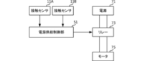
- FIG. 5 is a block diagram showing the configuration of the electric appliance 1.
- the electric appliance 1 includes a power supply control unit 51, a power supply 71, a relay 73, and a motor 75 as an electrical configuration.
- the relay 73 is connected to the power supply 71 and the motor 75.
- the relay 73 turns the power supply from the power supply 71 to the motor 75 on and off according to the control of the power supply control unit 51.
- the motor 75 and the drill form a main function unit 17.
- the power supply control unit 51 is composed of, for example, a microcomputer (microcontroller).
- the power supply control unit 51 controls the relay 73 according to the detection results of the contact sensor 11A and the contact sensor 11B.
- the power supply control unit 51 permits the power supply to the motor 75 by the relay 73.
- the power supply control unit 51 prohibits the power supply to the motor 75 by the relay 73 when the contact sensor 11A and the contact sensor 11B do not detect the contact of the user.
- the user supports the housing 10 by gripping the grip portion 15 as shown in the left side view of FIG.
- the main function portion 17 is arranged on the front side. Therefore, the user grips the grip portion 15 from the back side.
- the user is holding the grip portion 15 with his right hand. Therefore, the thumb wraps around from the left side surface of the grip portion 15 to the front side. Further, the space between the thumb and the index finger is located on the back side of the grip portion 15. In this way, when gripping the tubular grip portion 15 having a long axis in the vertical direction, the user turns the thumb from the left side surface to the front side to sandwich the grip portion 15 between the thumb and the index finger.
- the contact sensor 11A of the present embodiment is arranged on the back side of the grip portion 15. Further, the contact sensor 11B is arranged on the left side surface side of the grip portion 15. That is, the contact sensor 11A and the contact sensor 11B are arranged on the surface opposite to the main function portion 17 (second direction) and the side surface thereof, which correspond to the positions of the thumb and its surroundings.
- FIG. 6A is a left side view of the electric appliance 1 when four contact sensors are temporarily arranged
- FIG. 6B is a diagram showing the relationship between the arrangement of the contact sensors and the output of each contact sensor. Is.
- the vertical axis of the graph shown in FIG. 6B corresponds to the output of the contact sensor.
- the contact sensor 90A is arranged on the front side of the grip portion 15.
- the contact sensor 90B is arranged on the right side surface side of the grip portion 15.
- the contact sensor 11A and the contact sensor 11B arranged at the thumb and its surrounding positions show high output.
- the contact sensor 90A and the contact sensor 90B arranged at positions other than these show low output.
- the power supply control unit 51 sets the threshold value to a value higher than the output values of the contact sensor 90A and the contact sensor 90B shown in FIG. 6B and lower than the output values of the contact sensor 11A and the contact sensor 11B. When the power supply control unit 51 detects an output exceeding the threshold value from the contact sensor 11A and the contact sensor 11B, it determines that the user has gripped the grip unit 15.
- the power supply control unit 51 detects an output exceeding the threshold value not only from the contact sensor 11A and the contact sensor 11B but also from the contact sensor 90A and / or the contact sensor 90B, noise due to vibration or the like is mixed in or the grip portion is removed.
- the operation of the main function unit 17 may be stopped by determining an abnormal state such as improper gripping.
- at least one of the contact sensor 90A and the contact sensor 90B may be arranged on the electric appliance 1.
- the power supply control unit 51 can reliably detect the presence or absence of gripping by the user.
- the power supply control unit 51 supplies power to the motor 75 only when it is determined that the user has gripped the grip unit 15. Therefore, in the electric appliance 1, the main function portion 17 (drill in the present embodiment) operates only when the user grips the grip portion 15, so that very high safety can be realized.
- two contact sensors 11A and contact sensors 11B are shown as contact sensors arranged on the opposite side of the main function unit side, but the number of contact sensors is not limited to this example.
- only one contact sensor 11A may be arranged.
- the contact sensor may be arranged on the left side surface and the back surface side of the housing 10 so that the user can grip the grip portion 15 with his / her right hand.
- the contact sensor may be arranged on the right side surface of the housing 10 so that the user grips the grip portion 15 with the left hand.
- the contact sensors may be arranged on both the left side surface and the right side surface of the housing 10. In this case, the electric appliance 1 can detect the grip of the user regardless of whether it is gripped by the right hand or the left hand.
- any one of the contact sensors on the left side surface or the right side surface of the housing 10 may be enabled.
- the appliance 1 may include a changeover switch for switching the contact sensor to be enabled. In this case, the electric appliance 1 can detect the grip more reliably.
- an illuminance sensor As the contact sensor, an illuminance sensor, a capacitance sensor, an acceleration sensor, a strain gauge, a piezoelectric film, a piezoelectric ceramic, or the like can be used. It is particularly preferable to use a piezoelectric film as the contact sensor.
- the piezoelectric film can be attached to the housing to form a contact sensor, it is not necessary to perform processing such as making a hole in the housing. Further, since the output value of the piezoelectric film does not fluctuate even when water droplets adhere to it like a capacitance sensor, it can be used even in a situation where moisture adheres to the sensor or the housing. Further, unlike the acceleration sensor, the piezoelectric film directly detects the distortion of the housing, so that it does not detect external vibration. Further, the piezoelectric film shows an output value only when the housing is dynamically distorted. The piezoelectric film produces no output if there is no change in strain.
- the piezoelectric film does not react (the output value is small) when, for example, a temperature change causes a gradual expansion or contraction of the housing. Therefore, the piezoelectric film does not erroneously detect even if the housing expands or contracts due to a temperature change.
- Piezoelectric film is more flexible than piezoelectric ceramics, so a contact sensor with a larger area can be attached to a curved surface. As a result, the piezoelectric film can detect the contact with the curved surface more accurately. Further, even when a strong impact such as dropping is applied, the piezoelectric film is flexible and is unlikely to be damaged. As a result, the piezoelectric film can realize a more durable contact sensor.
- the contact sensor 11A may be a capacitance sensor and the contact sensor 11B may be a piezoelectric film sensor.
- the electric appliance 1 may include a sensor of a different type.
- the piezoelectric sensor for example, PVDF (Poly Vinylidene Di Fluoride) or polylactic acid (PLA: Polylactic Acid) can be used.
- Polylactic acid is a piezoelectric polymer that does not have pyroelectricity.
- Polylactic acid is uniaxially stretched to produce piezoelectricity. Since polylactic acid produces piezoelectricity in the molecular orientation treatment by stretching, it is not necessary to perform polling treatment unlike PVDF.
- polylactic acid does not have pyroelectricity. Therefore, polylactic acid does not cause a large change in the output value of the sensor due to the heat of the user or the heat generated by the electric appliance. Therefore, polylactic acid is suitable when it is placed in a portion gripped by the user for the present embodiment.
- uniaxially stretched polylactic acid has a very high piezoelectric constant among polymers. Furthermore, the piezoelectric constant of polylactic acid does not fluctuate with time and is extremely stable.
- the piezoelectric film is polylactic acid
- FIG. 7 is a left side view of the electric appliance 1 further provided with the trigger lever 77.
- the same configurations as those in FIG. 4 are designated by the same reference numerals, and the description thereof will be omitted.
- the trigger lever 77 is arranged on the front side of the grip portion 15. That is, the trigger lever 77 is arranged on the second direction side of the housing 10 where the main function portion 17 is arranged.
- FIG. 8 is a block diagram showing the configuration of the electric appliance 1 provided with the trigger lever 77.
- the same configurations as those in FIG. 5 are designated by the same reference numerals, and the description thereof will be omitted.
- the electric appliance 1 according to the example of FIG. 8 further includes a relay 73B and an operation detection unit 79.
- the relay 73B is inserted between the power supply 71 and the motor 75.
- the trigger lever 77 and the operation detection unit 79 constitute the reception unit of the present invention.
- the relay 73B is connected to the operation detection unit 79.
- the operation detection unit 79 is connected to the trigger lever 77.
- the operation detection unit 79 includes, for example, a microcomputer.
- the operation detection unit 79 detects on / off of the trigger lever 77.
- the operation detection unit 79 permits the relay 73B to supply power to the motor 75.
- the operation detection unit 79 prohibits the power supply to the motor 75 by the relay 73B when the trigger lever 77 is off.
- the user operates the trigger lever 77 with the index finger. Even in this case, as shown in FIG. 7, the user grips the grip portion 15 from the back side.
- the contact sensor 11A is arranged at a position facing the trigger lever 77. When the user grips the trigger lever 77 with the index finger, the grip portion 15 is strongly sandwiched between the thumb and the index finger. Therefore, the output value of the contact sensor 11A becomes high.
- the electric appliance 1 can reliably detect the presence or absence of gripping by the user by arranging the contact sensor 11A at the position facing the trigger lever 77.
- FIG. 9 is a block diagram showing the configuration of the electric appliance 1 having the lock-on function.
- the configurations common to those in FIG. 8 are designated by the same reference numerals, and the description thereof will be omitted.
- the electric appliance 1 shown in FIG. 9 further includes a lock-on switch 91.
- the lock-on switch 91 is connected to the operation detection unit 79.
- the operation detection unit 79 detects whether the lock-on switch 91 is on or off.
- the operation detection unit 79 permits the relay 73B to supply power to the motor 75 regardless of whether the trigger lever 77 is on or off. Therefore, the user can operate the main function unit 17 without operating the trigger lever 77.
- the power supply control unit 51 prohibits the power supply to the motor 75 by the relay 73 when the contact sensor 11A and the contact sensor 11B do not detect the contact of the user. Therefore, by turning on the lock-on switch 91, even if the main function unit 17 is operating without operating the trigger lever 77, when the user releases the grip portion 15, the main function unit 17 is operated. Stops.
- the electric appliance 1 of the present embodiment can realize high safety even when it has a lock-on function.
- the trigger lever 77 is latched, the same function as the lock-on function can be realized.
- the power supply control unit 51 prohibits the power supply to the motor 75 by the relay 73 when the contact sensor 11A and the contact sensor 11B do not detect the contact of the user. Therefore, even when the trigger lever 77 is latched in the ON state, the main function portion 17 stops when the user releases the grip portion 15.
- the power supply control unit 51 sets the contact sensor 11A and the contact sensor 11A until the main power supply (not shown) of the electric appliance 1 is turned on and restarted. Even when the contact sensor 11B detects the user's contact, it is preferable to prohibit the power supply to the motor 75 by the relay 73. As a result, even if the user grips the grip portion 15 again, the main function portion 17 does not operate unintentionally.
- FIG. 10 is a rear view of the electric appliance 1 further provided with the second grip portion 19.
- the configurations common to those in FIG. 1 are designated by the same reference numerals, and the description thereof will be omitted.
- the electric appliance 1 shown in FIG. 10 is provided with a second grip portion 19 on the left side surface side of the upper portion of the housing 10.
- the grip portion 15 corresponds to the first grip portion.
- a contact sensor 11C is arranged on the second grip portion 19.
- the contact sensor 11C is arranged on the lower surface side of the second grip portion 19.
- the second grip portion 19 has a long axis along the left-right direction (the third direction intersecting the first direction and the second direction).
- the user grips the second grip portion 19 with his left hand.
- the thumb of the left hand wraps around from the lower surface of the second grip portion 19 to the front side. Further, the space between the thumb and the index finger of the left hand is located on the back side of the second grip portion 19.
- the second grip portion 19 does not need to have a long axis along the left-right direction.
- the third direction, which is the long axis of the second grip portion 19, may at least intersect the first direction, which is the long axis of the grip portion 15, and the second direction in which the main function portion 17 is arranged.
- the power supply control unit 51 When the power supply control unit 51 detects an output exceeding the threshold value from the contact sensor 11C, it determines that the user has gripped the second grip unit 19. As a result, the power supply control unit 51 can reliably detect the presence or absence of gripping the second gripping unit 19 of the user.
- the power supply control unit 51 supplies power to the motor 75 only when the user grips both the grip portion 15 and the second grip portion 19. Therefore, the electric appliance 1 realizes higher safety because the main function portion 17 (drill in the present embodiment) operates only when the user grips both the grip portion 15 and the second grip portion 19. can do.
- the contact sensor 11B is arranged on the side where the second grip portion 19 is arranged.
- the second grip portion is arranged on the left side surface side of the housing as shown in FIG. 10
- the user grips the first grip portion with the right hand and grips the second grip portion with the left hand.
- the second grip portion is arranged on the right side surface side of the housing
- the user grips the first grip portion with his left hand and grips the second grip portion with his right hand.
- the contact sensor second grip portion when the contact sensor second grip portion is provided, the user turns his thumb toward the second grip portion when gripping the first grip portion. Therefore, when the contact sensor is arranged on the grip portion 15, the contact sensor may be arranged on the third direction side in which the second grip portion is provided.
- the second grip portion may be detachable. In this case, the contact sensor 11C and the power supply control unit 51 arranged in the second grip portion can be electrically connected by the fitting portion between the second grip portion and the housing 10.
- FIGS. 11A and 11B are rear views of the electric appliance 1 provided with the attachment 151. As shown in FIGS. 11A and 11B, the contact sensor 11A and the contact sensor 11B are configured to be detachable from the grip portion 15 via the attachment 151.
- the contact sensor 11A and the contact sensor 11B are electrically connected to an internal electric circuit (power supply control unit 51 shown in FIG. 5) via a terminal 101 provided on the grip portion 15.
- the contact sensor 11A and the contact sensor 11B are separated from the housing 10, so that the vibration of the housing 10 is less likely to be transmitted. Therefore, the possibility of erroneous detection in response to the vibration of the housing 10 is reduced. Further, by arranging a cushion or the like between the attachment 151 and the grip portion 15, it is possible to make it difficult for the vibration of the housing 10 to be transmitted by the contact sensor 11A and the contact sensor 11B.
- the assembly process of the housing 10 can be simplified.
- the power supply control unit 51 may be incorporated in the attachment 151. In this case, it is not necessary to incorporate the power supply control unit 51 in the housing 10. Therefore, the assembly process can be further simplified.
- FIG. 12A many electric appliances are divided into left and right along a dividing line in the vertical direction of the housing 10, and a motor 75 and an electric circuit 150 are arranged in one of them.
- parts such as the motor 75 and the electric circuit 150 can be easily arranged inside the housing 10, and the assembly process can be simplified.
- the contact sensor cannot be arranged long to the left and right across the dividing line.
- the attachment 151 since the attachment 151 is separated from the housing 10, it can be lengthened to the left and right across the dividing line. Therefore, by using the attachment 151, it is possible to arrange the contact sensor 11N which is long in the left-right direction in the housing 10.
- a sensor other than the contact sensor can be mounted on the attachment 151.
- a speaker can be mounted on the attachment 151 to realize an alarm function.
- the control unit mounted on the attachment 151 detects the capacity of the battery and sounds an alarm when the battery becomes equal to or less than the reference value.
- an indicator such as an LED can be mounted on the attachment 151.
- the power supply control unit 51 mounted on the attachment 151 turns on the LED when the user's grip is detected.
- the attachment 151 may be equipped with a personal authentication sensor such as a fingerprint sensor.
- the power supply control unit 51 permits power supply only when the personal information of the user registered in advance is detected via the personal authentication sensor. Therefore, only the pre-registered user can use the electric appliance 1. As a result, the use can be limited to specific users such as qualified persons.
- a memory may be further mounted on the attachment 151. The power supply control unit 51 records the operating time in the memory. This makes it possible to record the working time of the user registered in advance.
- Electric appliance 10 Housing 11A, 11B, 11C, 11N, 90A, 90B ... Contact sensor 15 ... Gripping part 17 ... Main function part 19 ... Second gripping part 51 ... Power supply control unit 71 ... Power supply 73, 73B ... Relay 75 ... Motor 77 ... Trigger lever 79 ... Operation detection unit 91 ... Lock-on switch 101 ... Terminal 150 ... Electric circuit 151 ... Attachment
Landscapes
- Engineering & Computer Science (AREA)
- Mechanical Engineering (AREA)
- Portable Power Tools In General (AREA)
Priority Applications (1)
| Application Number | Priority Date | Filing Date | Title |
|---|---|---|---|
| JP2021527486A JP7184190B2 (ja) | 2019-06-25 | 2020-05-21 | 電気器具 |
Applications Claiming Priority (2)
| Application Number | Priority Date | Filing Date | Title |
|---|---|---|---|
| JP2019-116897 | 2019-06-25 | ||
| JP2019116897 | 2019-06-25 |
Publications (1)
| Publication Number | Publication Date |
|---|---|
| WO2020261827A1 true WO2020261827A1 (ja) | 2020-12-30 |
Family
ID=74059669
Family Applications (1)
| Application Number | Title | Priority Date | Filing Date |
|---|---|---|---|
| PCT/JP2020/020040 Ceased WO2020261827A1 (ja) | 2019-06-25 | 2020-05-21 | 電気器具 |
Country Status (2)
| Country | Link |
|---|---|
| JP (1) | JP7184190B2 (https=) |
| WO (1) | WO2020261827A1 (https=) |
Cited By (1)
| Publication number | Priority date | Publication date | Assignee | Title |
|---|---|---|---|---|
| WO2024185461A1 (ja) * | 2023-03-03 | 2024-09-12 | オムロン株式会社 | 電動把持工具および電動把持工具の制御方法、制御プログラム |
Citations (3)
| Publication number | Priority date | Publication date | Assignee | Title |
|---|---|---|---|---|
| JP2009220213A (ja) * | 2008-03-17 | 2009-10-01 | Hitachi Koki Co Ltd | 電動工具 |
| JP2015076980A (ja) * | 2013-10-09 | 2015-04-20 | シャープ株式会社 | 操作装置及び移動体 |
| WO2017051892A1 (ja) * | 2015-09-25 | 2017-03-30 | 株式会社マキタ | グラインダ |
Family Cites Families (2)
| Publication number | Priority date | Publication date | Assignee | Title |
|---|---|---|---|---|
| JPH0448943Y2 (https=) * | 1985-02-08 | 1992-11-18 | ||
| JPH0435887U (https=) * | 1990-07-23 | 1992-03-25 |
-
2020
- 2020-05-21 WO PCT/JP2020/020040 patent/WO2020261827A1/ja not_active Ceased
- 2020-05-21 JP JP2021527486A patent/JP7184190B2/ja active Active
Patent Citations (3)
| Publication number | Priority date | Publication date | Assignee | Title |
|---|---|---|---|---|
| JP2009220213A (ja) * | 2008-03-17 | 2009-10-01 | Hitachi Koki Co Ltd | 電動工具 |
| JP2015076980A (ja) * | 2013-10-09 | 2015-04-20 | シャープ株式会社 | 操作装置及び移動体 |
| WO2017051892A1 (ja) * | 2015-09-25 | 2017-03-30 | 株式会社マキタ | グラインダ |
Cited By (1)
| Publication number | Priority date | Publication date | Assignee | Title |
|---|---|---|---|---|
| WO2024185461A1 (ja) * | 2023-03-03 | 2024-09-12 | オムロン株式会社 | 電動把持工具および電動把持工具の制御方法、制御プログラム |
Also Published As
| Publication number | Publication date |
|---|---|
| JPWO2020261827A1 (https=) | 2020-12-30 |
| JP7184190B2 (ja) | 2022-12-06 |
Similar Documents
| Publication | Publication Date | Title |
|---|---|---|
| US11897113B2 (en) | Hand held power tool with a human machine interface | |
| EP2747948B1 (en) | Guide and control assembly | |
| US20210100170A1 (en) | Hedge trimmer | |
| US20200180132A1 (en) | Hand-Held Power Tool | |
| US20230049404A1 (en) | Rotary type gripping device for electrical hedge trimmer | |
| GB2211544A (en) | Key device incorporating an electronic circuit | |
| EP3675348B1 (en) | Electric working machine | |
| WO2020261827A1 (ja) | 電気器具 | |
| CN213646136U (zh) | 电动工具 | |
| CN112548956A (zh) | 手持式工具机和用于运行手持式工具机的方法 | |
| WO2011103636A1 (en) | Modular power tool | |
| JP2018083261A (ja) | 手動パルス発生装置 | |
| US12427642B2 (en) | Hand-held power tool with a fastening region for a safety loop | |
| US6734379B1 (en) | Electronic power tool lock-out mechanism | |
| CN115151128A (zh) | 具有安全引导电动器具的至少一个手柄的电动器具和运行电动器具的方法 | |
| CN112108712A (zh) | 锯切工具机 | |
| CN103978465B (zh) | 手持式工具机 | |
| DK3300869T3 (en) | TABLE SAFETY AND A PULL OF SHOP | |
| US20210283761A1 (en) | Method for Enabling an Active Operating State of a Hand-Held Power Tool According to Whether an Item of Protective Equipment is Carried or Worn by an Operator of the Hand-Held Power Tool | |
| WO2021131510A1 (ja) | 作業機 | |
| JP6693602B2 (ja) | 押圧検知センサ及び電子機器 | |
| CN117320846A (zh) | 具有安全开关的手持式动力工具 | |
| CN113001477B (zh) | 具有手指防护件的手持式工具机 | |
| WO2024185455A1 (ja) | 電動把持工具の使用状況管理装置およびこれを備えた使用状況管理システム | |
| SE511969C2 (sv) | Tvåhandsmanövrering av arbetsmaskiner |
Legal Events
| Date | Code | Title | Description |
|---|---|---|---|
| 121 | Ep: the epo has been informed by wipo that ep was designated in this application |
Ref document number: 20832347 Country of ref document: EP Kind code of ref document: A1 |
|
| ENP | Entry into the national phase |
Ref document number: 2021527486 Country of ref document: JP Kind code of ref document: A |
|
| NENP | Non-entry into the national phase |
Ref country code: DE |
|
| 122 | Ep: pct application non-entry in european phase |
Ref document number: 20832347 Country of ref document: EP Kind code of ref document: A1 |