WO2020261688A1 - 心機能測定システム、体外循環装置および心機能測定プログラム - Google Patents
心機能測定システム、体外循環装置および心機能測定プログラム Download PDFInfo
- Publication number
- WO2020261688A1 WO2020261688A1 PCT/JP2020/014809 JP2020014809W WO2020261688A1 WO 2020261688 A1 WO2020261688 A1 WO 2020261688A1 JP 2020014809 W JP2020014809 W JP 2020014809W WO 2020261688 A1 WO2020261688 A1 WO 2020261688A1
- Authority
- WO
- WIPO (PCT)
- Prior art keywords
- flow rate
- blood
- patient
- cardiac function
- withdrawal
- Prior art date
Links
Images


Classifications
-
- A—HUMAN NECESSITIES
- A61—MEDICAL OR VETERINARY SCIENCE; HYGIENE
- A61B—DIAGNOSIS; SURGERY; IDENTIFICATION
- A61B5/00—Measuring for diagnostic purposes; Identification of persons
- A61B5/48—Other medical applications
- A61B5/4836—Diagnosis combined with treatment in closed-loop systems or methods
-
- A—HUMAN NECESSITIES
- A61—MEDICAL OR VETERINARY SCIENCE; HYGIENE
- A61B—DIAGNOSIS; SURGERY; IDENTIFICATION
- A61B5/00—Measuring for diagnostic purposes; Identification of persons
- A61B5/02—Detecting, measuring or recording pulse, heart rate, blood pressure or blood flow; Combined pulse/heart-rate/blood pressure determination; Evaluating a cardiovascular condition not otherwise provided for, e.g. using combinations of techniques provided for in this group with electrocardiography or electroauscultation; Heart catheters for measuring blood pressure
- A61B5/026—Measuring blood flow
-
- A—HUMAN NECESSITIES
- A61—MEDICAL OR VETERINARY SCIENCE; HYGIENE
- A61M—DEVICES FOR INTRODUCING MEDIA INTO, OR ONTO, THE BODY; DEVICES FOR TRANSDUCING BODY MEDIA OR FOR TAKING MEDIA FROM THE BODY; DEVICES FOR PRODUCING OR ENDING SLEEP OR STUPOR
- A61M1/00—Suction or pumping devices for medical purposes; Devices for carrying-off, for treatment of, or for carrying-over, body-liquids; Drainage systems
- A61M1/36—Other treatment of blood in a by-pass of the natural circulatory system, e.g. temperature adaptation, irradiation ; Extra-corporeal blood circuits
- A61M1/3621—Extra-corporeal blood circuits
- A61M1/3666—Cardiac or cardiopulmonary bypass, e.g. heart-lung machines
-
- A—HUMAN NECESSITIES
- A61—MEDICAL OR VETERINARY SCIENCE; HYGIENE
- A61M—DEVICES FOR INTRODUCING MEDIA INTO, OR ONTO, THE BODY; DEVICES FOR TRANSDUCING BODY MEDIA OR FOR TAKING MEDIA FROM THE BODY; DEVICES FOR PRODUCING OR ENDING SLEEP OR STUPOR
- A61M60/00—Blood pumps; Devices for mechanical circulatory actuation; Balloon pumps for circulatory assistance
- A61M60/10—Location thereof with respect to the patient's body
- A61M60/104—Extracorporeal pumps, i.e. the blood being pumped outside the patient's body
- A61M60/109—Extracorporeal pumps, i.e. the blood being pumped outside the patient's body incorporated within extracorporeal blood circuits or systems
-
- A—HUMAN NECESSITIES
- A61—MEDICAL OR VETERINARY SCIENCE; HYGIENE
- A61M—DEVICES FOR INTRODUCING MEDIA INTO, OR ONTO, THE BODY; DEVICES FOR TRANSDUCING BODY MEDIA OR FOR TAKING MEDIA FROM THE BODY; DEVICES FOR PRODUCING OR ENDING SLEEP OR STUPOR
- A61M60/00—Blood pumps; Devices for mechanical circulatory actuation; Balloon pumps for circulatory assistance
- A61M60/20—Type thereof
- A61M60/205—Non-positive displacement blood pumps
- A61M60/216—Non-positive displacement blood pumps including a rotating member acting on the blood, e.g. impeller
- A61M60/226—Non-positive displacement blood pumps including a rotating member acting on the blood, e.g. impeller the blood flow through the rotating member having mainly radial components
- A61M60/232—Centrifugal pumps
-
- A—HUMAN NECESSITIES
- A61—MEDICAL OR VETERINARY SCIENCE; HYGIENE
- A61M—DEVICES FOR INTRODUCING MEDIA INTO, OR ONTO, THE BODY; DEVICES FOR TRANSDUCING BODY MEDIA OR FOR TAKING MEDIA FROM THE BODY; DEVICES FOR PRODUCING OR ENDING SLEEP OR STUPOR
- A61M60/00—Blood pumps; Devices for mechanical circulatory actuation; Balloon pumps for circulatory assistance
- A61M60/30—Medical purposes thereof other than the enhancement of the cardiac output
- A61M60/36—Medical purposes thereof other than the enhancement of the cardiac output for specific blood treatment; for specific therapy
- A61M60/38—Blood oxygenation
-
- A—HUMAN NECESSITIES
- A61—MEDICAL OR VETERINARY SCIENCE; HYGIENE
- A61M—DEVICES FOR INTRODUCING MEDIA INTO, OR ONTO, THE BODY; DEVICES FOR TRANSDUCING BODY MEDIA OR FOR TAKING MEDIA FROM THE BODY; DEVICES FOR PRODUCING OR ENDING SLEEP OR STUPOR
- A61M60/00—Blood pumps; Devices for mechanical circulatory actuation; Balloon pumps for circulatory assistance
- A61M60/50—Details relating to control
- A61M60/508—Electronic control means, e.g. for feedback regulation
- A61M60/515—Regulation using real-time patient data
- A61M60/523—Regulation using real-time patient data using blood flow data, e.g. from blood flow transducers
-
- A—HUMAN NECESSITIES
- A61—MEDICAL OR VETERINARY SCIENCE; HYGIENE
- A61M—DEVICES FOR INTRODUCING MEDIA INTO, OR ONTO, THE BODY; DEVICES FOR TRANSDUCING BODY MEDIA OR FOR TAKING MEDIA FROM THE BODY; DEVICES FOR PRODUCING OR ENDING SLEEP OR STUPOR
- A61M60/00—Blood pumps; Devices for mechanical circulatory actuation; Balloon pumps for circulatory assistance
- A61M60/50—Details relating to control
- A61M60/508—Electronic control means, e.g. for feedback regulation
- A61M60/538—Regulation using real-time blood pump operational parameter data, e.g. motor current
- A61M60/546—Regulation using real-time blood pump operational parameter data, e.g. motor current of blood flow, e.g. by adapting rotor speed
-
- A—HUMAN NECESSITIES
- A61—MEDICAL OR VETERINARY SCIENCE; HYGIENE
- A61M—DEVICES FOR INTRODUCING MEDIA INTO, OR ONTO, THE BODY; DEVICES FOR TRANSDUCING BODY MEDIA OR FOR TAKING MEDIA FROM THE BODY; DEVICES FOR PRODUCING OR ENDING SLEEP OR STUPOR
- A61M60/00—Blood pumps; Devices for mechanical circulatory actuation; Balloon pumps for circulatory assistance
- A61M60/50—Details relating to control
- A61M60/585—User interfaces
-
- A—HUMAN NECESSITIES
- A61—MEDICAL OR VETERINARY SCIENCE; HYGIENE
- A61M—DEVICES FOR INTRODUCING MEDIA INTO, OR ONTO, THE BODY; DEVICES FOR TRANSDUCING BODY MEDIA OR FOR TAKING MEDIA FROM THE BODY; DEVICES FOR PRODUCING OR ENDING SLEEP OR STUPOR
- A61M2205/00—General characteristics of the apparatus
- A61M2205/33—Controlling, regulating or measuring
- A61M2205/3331—Pressure; Flow
- A61M2205/3334—Measuring or controlling the flow rate
-
- A—HUMAN NECESSITIES
- A61—MEDICAL OR VETERINARY SCIENCE; HYGIENE
- A61M—DEVICES FOR INTRODUCING MEDIA INTO, OR ONTO, THE BODY; DEVICES FOR TRANSDUCING BODY MEDIA OR FOR TAKING MEDIA FROM THE BODY; DEVICES FOR PRODUCING OR ENDING SLEEP OR STUPOR
- A61M2205/00—General characteristics of the apparatus
- A61M2205/50—General characteristics of the apparatus with microprocessors or computers
- A61M2205/502—User interfaces, e.g. screens or keyboards
Definitions
- the present invention relates to a cardiac function measuring system, an extracorporeal circulatory device, and a cardiac function measuring program.
- PCPS invasive cardiopulmonary support
- ECPR extracorporeal cardiopulmonary resuscitation
- ECMO Extracorporeal Membrane Oxygenation
- the pump of the extracorporeal circulation device takes blood from the patient, passes it through the artificial lung, and returns the blood that has passed through the artificial lung to the patient.
- the direction of the blood flow returned to the patient's body by the pump is opposite to the direction of the blood flow flowing through the patient's body. That is, the pump returns the blood that has passed through the artificial lung to the patient in a retrograde state. Therefore, even when the flow sensor attached to the catheter is delivered in the vicinity of the patient's heart, it is difficult to measure the cardiac output of the heart alone. Therefore, in this case, it is difficult to judge the recovery of the patient's cardiac function with high accuracy.
- Patent Document 1 discloses a cardiac function evaluation device that calculates the time derivative of the blood flow rate measured by a blood flow meter and evaluates the cardiac function based on the calculation result.
- the cardiac function evaluation device described in Patent Document 1 converts the time derivative of blood flow rate into the time derivative of blood pressure.
- the relationship between the time derivative of blood flow rate and the time derivative of blood pressure is described in FIG. 2 of Patent Document 1.
- the error of the time derivative of blood pressure is relatively large even though the cardiac function evaluation block including the blood flow meter is provided near the heart of the patient. Therefore, as described above, even when the blood flow meter is provided near the patient's heart, it is difficult to judge the recovery of the patient's cardiac function with high accuracy.
- the present invention has been made to solve the above problems, and provides a cardiac function measuring system, an extracorporeal circulation device, and a cardiac function measuring program capable of determining the recovery of a patient's cardiac function with high accuracy.
- the purpose is a cardiac function measuring system, an extracorporeal circulation device, and a cardiac function measuring program capable of determining the recovery of a patient's cardiac function with high accuracy.
- the subject is a cardiac function measuring system that is installed in an extracorporeal circulation device and measures a patient's cardiac function.
- the number of revolutions of a pump that takes out blood from the patient and returns the blood to the patient is detected.
- the discharge pressure of the pump is determined
- the withdrawal reference flow rate indicating the theoretical flow rate of the blood discharged from the pump is determined based on the discharge pressure
- the blood flowing through the circulation circuit of the extracorporeal circulation device is determined.
- the measured blood flow rate indicating the realistic flow rate of the blood is determined based on the measurement result of the flow rate measuring unit for measuring the flow rate of the blood
- the extracorporeal circulation is based on the comparison between the withdrawal reference flow rate and the measured blood flow rate. It is solved by the cardiac function measuring system according to the present invention, which is characterized in determining the timing of withdrawal of the device.
- the cardiac function measuring system determines a withdrawal reference flow rate indicating a theoretical flow rate of blood pumped from a pump based on a pump discharge pressure determined based on the rotation speed of the pump. To do.
- the cardiac function measuring system determines the measured blood flow rate indicating the realistic flow rate of blood based on the measurement result of the flow rate measuring unit that measures the flow rate of blood flowing through the circulation circuit of the extracorporeal circulation device. Then, the cardiac function measuring system determines the timing of withdrawal of the extracorporeal circulatory device based on the comparison between the withdrawal reference flow rate and the measured blood flow rate.
- the cardiac function measuring system compares the withdrawal reference flow rate and the measured blood flow rate with relatively little change with time with each other, and determines the timing of withdrawal of the extracorporeal circulation device. As a result, the cardiac function measuring system according to the present invention can determine the recovery of the patient's cardiac function with high accuracy.
- the cardiac function measuring system preferably, calculates a parameter indicating a comparison between the withdrawal reference flow rate and the measured blood flow rate, and determines the timing of withdrawal of the extracorporeal circulation device based on the parameter. It is a feature.
- the pumping ability of a patient is quantitatively measured by calculating a parameter indicating a comparison between the withdrawal reference flow rate and the measured cardiac output, and the withdrawal of the extracorporeal circulation device is performed. Timing can be determined based on quantitative comparisons. As a result, the cardiac function measuring system according to the present invention can determine the recovery of the patient's cardiac function with high accuracy.
- the parameter is preferably a difference parameter representing the difference between the withdrawal reference flow rate and the measured blood flow rate.
- the withdrawal reference flow rate and the measurement are used as parameters indicating the comparison between the withdrawal reference flow rate and the measured blood flow rate by using a relatively simple mathematical formula or a table or the like.
- the difference parameter representing the difference from the blood flow rate can be calculated, and the pumping ability of the patient can be quantitatively measured.
- the cardiac function measuring system according to the present invention can determine the recovery of the patient's cardiac function easily and with high accuracy.
- the cardiac function measuring system according to the present invention is preferably characterized in that a graph showing the relationship between the parameter and the elapsed time and the parameter are displayed on the display unit.
- the operator or the like can easily compare the withdrawal reference flow rate and the measured blood flow rate by checking the display unit, and visually check the withdrawal timing of the extracorporeal circulation device. Can be grasped.
- the cardiac function measuring system according to the present invention is preferably characterized in that a graph showing the relationship between the rotation speed, the withdrawal reference flow rate, and the measured blood flow rate is displayed on the display unit.
- the operator or the like can easily compare the withdrawal reference flow rate and the measured blood flow rate by checking the display unit, and visually check the withdrawal timing of the extracorporeal circulation device. Can be grasped.
- the cardiac function measuring system according to the present invention is preferably characterized in that when the timing of withdrawal becomes appropriate, the display unit notifies that the timing of withdrawal is appropriate.
- the surgeon or the like can easily visually determine whether or not the timing of withdrawal of the extracorporeal circulatory device is appropriate by checking the notification displayed on the display unit. Can be grasped.
- the cardiac function measurement system according to the present invention can prevent the timing of withdrawal of the extracorporeal circulatory device from being too early than the recovery of the patient's cardiac function, and can efficiently determine the timing of withdrawal of the extracorporeal circulatory device. Can be assisted.
- the cardiac function measuring system preferably notifies the display unit that the withdrawal timing is late when a predetermined time elapses after the display unit notifies that the withdrawal timing is appropriate. It is characterized by doing.
- the operator or the like can easily visually grasp whether or not the timing of withdrawal of the extracorporeal circulatory device is late by checking the notification displayed on the display unit. be able to.
- the cardiac function measurement system according to the present invention can prevent the timing of withdrawal of the extracorporeal circulatory device from being too late for the recovery of the patient's cardiac function, and can efficiently determine the timing of withdrawal of the extracorporeal circulatory device. Can be assisted.
- the measured flow rate is an average flow rate indicating an average value of a plurality of the realistic flow rates measured at a predetermined time by a flow rate measuring unit. To do.
- the cardiac function measurement system compares the withdrawal reference flow rate and the measured cardiac output with each other while suppressing the influence of the heart beat, which has a relatively large change with time, and pumps the patient.
- the ability can be quantitatively measured to determine the timing of withdrawal of the extracorporeal circulation device.
- the cardiac function measuring system can determine the recovery of the patient's cardiac function with even higher accuracy.
- the subject is an extracorporeal circulation device that circulates blood extracorporeally using a circulation circuit, a blood removal side catheter that guides the blood that is partially inserted into the patient and taken out from the patient, and blood is taken out from the patient.
- a pump for returning the blood to the patient a blood feeding side catheter provided on the downstream side of the pump and a part of the blood being inserted into the patient and pumped from the pump to guide the blood to the patient, and the circulation.
- the problem is solved by the extracorporeal circulation device according to the present invention, which comprises a flow rate measuring unit provided in the circuit and measuring the flow rate of the blood flowing through the circulation circuit, and any of the above-mentioned cardiac function measuring systems.
- the cardiac function measuring system indicates a withdrawal reference flow rate indicating a theoretical flow rate of blood pumped from a pump based on a pump discharge pressure determined based on the rotation speed of the pump. To determine. In addition, the cardiac function measuring system determines the measured blood flow rate indicating the realistic flow rate of blood based on the measurement result of the flow rate measuring unit that measures the flow rate of blood flowing through the circulation circuit of the extracorporeal circulation device. Then, the cardiac function measuring system determines the timing of withdrawal of the extracorporeal circulatory device based on the comparison between the withdrawal reference flow rate and the measured blood flow rate.
- the cardiac function measuring system compares the withdrawal reference flow rate and the measured blood flow rate with relatively little change with time with each other, and determines the timing of withdrawal of the extracorporeal circulatory device.
- the extracardiac circulatory device according to the present invention can determine the recovery of the patient's cardiac function with high accuracy.
- the subject is a cardiac function measuring program executed by a computer of a cardiac function measuring system installed in an extracorporeal circulation device and measuring a patient's cardiac function, wherein the computer draws blood from the patient and the patient receives the blood.
- the rotation speed of the pump that returns blood is detected, the discharge pressure of the pump is determined based on the rotation speed, and the withdrawal reference flow rate indicating the theoretical flow rate of the blood discharged from the pump is determined based on the discharge pressure.
- the cardiac function measurement program according to the present invention, which comprises executing a step of determining the timing of withdrawal of the extracorporeal circulation device based on the comparison with the measured blood flow rate.
- the cardiac function measurement program determines a withdrawal reference flow rate indicating the theoretical flow rate of blood pumped from the pump based on the discharge pressure of the pump determined based on the rotation speed of the pump. Let me.
- the cardiac function measurement program determines the measured blood flow rate, which indicates the realistic flow rate of blood, based on the measurement result of the flow rate measuring unit that measures the flow rate of blood flowing through the circulation circuit of the extracorporeal circulation device. Then, the cardiac function measurement program determines the timing of withdrawal of the extracorporeal circulatory device based on the comparison between the withdrawal reference flow rate and the measured blood flow rate.
- the cardiac function measurement program compares the withdrawal reference flow rate and the measured blood flow rate with relatively little change over time with each other, and determines the timing of withdrawal of the extracorporeal circulatory device.
- the cardiac function measurement program according to the present invention the recovery of the patient's cardiac function can be determined with high accuracy.
- a cardiac function measuring system an extracorporeal circulation device, and a cardiac function measuring program capable of determining the recovery of a patient's cardiac function with high accuracy.
- FIG. 1 is a schematic view showing an extracorporeal circulation device according to an embodiment of the present invention.
- the "external circulation” performed by the extracorporeal circulation device 1 shown in FIG. 1 includes an “external circulation operation” and an “auxiliary circulation operation”.
- the extracorporeal circulation device 1 can perform both "extracorporeal circulation operation” and "auxiliary circulation operation”.
- Extracorporeal circulation operation refers to blood circulation operation and gas exchange operation (oxygen addition and / or carbon dioxide removal) for blood when blood circulation in the heart is temporarily stopped due to, for example, cardiac surgery. Is performed by the extracorporeal circulation device 1.
- the "auxiliary circulatory operation” is a blood circulation in a state where the heart of the patient P to which the extracorporeal circulatory device 1 is applied cannot perform a sufficient function or a state in which gas exchange by the lungs cannot be sufficiently performed. It means that the operation and the gas exchange operation for blood are also performed by the extracorporeal circulatory device 1.
- the "auxiliary circulation operation” is mainly taken as an example.
- the extracorporeal circulatory device 1 is applied when the heart of the patient P does not operate normally, or when the heart of the patient P operates normally but the lungs do not operate normally.
- the extracorporeal circulatory device 1 shown in FIG. 1 is used, for example, when performing cardiac surgery on patient P or in subsequent treatment in the ICU.
- the extracorporeal circulation device 1 shown in FIG. 1 operates the pump of the extracorporeal circulation device 1 to remove blood from a patient's vein, exchange gas in the blood with an artificial lung to oxygenate the blood, and then oxygenate the blood.
- An artificial lung extracorporeal blood circulation can be performed to return the converted blood to the patient's arteries or veins.
- the extracorporeal circulatory device 1 is a device that acts as a substitute for the heart and lungs.
- the extracorporeal circulatory device 1 has a circulation circuit 1R for circulating blood.
- the circulation circuit 1R includes an artificial lung 2, a centrifugal pump 3, a drive motor 4 for driving the centrifugal pump 3, a blood removal side catheter (venous side catheter) 5, a blood supply side catheter (arterial side catheter) 6, and the like. It has a cardiac function measuring system 10.
- the centrifugal pump 3 of the present embodiment is an example of the "pump" of the present invention.
- the cardiac function measurement system 10 has a control unit 40 and is provided as a controller of the extracorporeal circulatory device 1.
- the centrifugal pump 3 is also called a blood pump or the like, and may be a pump other than the centrifugal pump.
- the blood removal side catheter 5 is also called a venous side cannula (blood removal side cannula) and is inserted from the femoral vein. The tip of the blood removal side catheter 5 is placed in the right atrium.
- the blood removal side catheter 5 is connected to the blood removal tube (also referred to as a blood removal line) 11 via the connector 8 and is connected to the centrifugal pump 3 via the blood removal tube 11, and the blood taken out from the patient P. Is guided to the centrifugal pump 3 via the blood removal tube 11.
- the blood removal tube 11 is a pipe line connecting the blood removal side catheter 5 and the centrifugal pump 3, and is a pipe line for guiding the blood taken out from the patient P through the blood removal side catheter 5 to the centrifugal pump 3.
- the blood-sending catheter 6 is also called an arterial cannula (blood-sending cannula) and is inserted from the femoral artery.
- the blood feeding side catheter 6 is connected to the blood feeding tube (also referred to as a blood feeding line) 12 via the connector 9, and is connected to the artificial lung 2 via the blood feeding tube 12 and has passed through the artificial lung 2. Is led to patient P via the blood feeding tube 12.
- the blood feeding tube 12 is a pipe line connecting the artificial lung 2 and the blood feeding side catheter 6, and is a pipe line for guiding the blood passing through the artificial lung 2 to the patient P.
- the drive motor 4 controls the drive of the centrifugal pump 3 based on the command SG of the cardiac function measurement system 10.
- the centrifugal pump 3 is provided on the downstream side of the blood removal side catheter 5, and is driven by receiving a driving force transmitted from the drive motor 4.
- the centrifugal pump 3 takes out blood from the patient P via the blood removal side catheter 5 and the blood removal tube 11, sends the blood to the artificial lung 2, and then sends the blood to the patient P through the blood supply tube 12 and the blood supply side catheter 6. Return. Further, the centrifugal pump 3 transmits a signal G regarding the rotation speed of the centrifugal pump 3 to the cardiac function measuring system 10.
- the artificial lung 2 is provided on the downstream side of the centrifugal pump 3. Specifically, the artificial lung 2 is arranged between the centrifugal pump 3 and the blood feeding tube 12. The artificial lung 2 performs a gas exchange operation (oxygen addition and / or carbon dioxide removal) with respect to blood.
- the artificial lung 2 is, for example, a membrane type artificial lung, but a hollow fiber membrane type artificial lung is particularly preferable. Oxygen gas is supplied to the artificial lung 2 through the oxygen supply tube 14.
- a highly transparent, elastically deformable and flexible synthetic resin pipe such as a vinyl chloride resin or silicone rubber is used.
- the liquid blood flows in the V1 direction and the V2 direction in the blood removal tube 11, and flows in the V3 direction in the blood feeding tube 12.
- the cardiac function measurement system 10 acquires various information, performs calculations, generates control signals for controlling the operation of devices such as the drive motor 4 and the external monitor 16, and transmits them to each device. In other words, the cardiac function measuring system 10 manages the extracorporeal circulatory device 1. Details of the cardiac function measurement system 10 will be described later. Further, the cardiac function measurement system 10 may have a touch panel 52 (see FIG. 5) as an input unit capable of inputting various information and as a display unit displaying various information. That is, the "display unit" of the present invention may be an external monitor 16 provided separately from the cardiac function measuring system 10, or may be a touch panel 52 included in the cardiac function measuring system 10. The touch panel 52 is capable of detecting contact with a finger of an operator or the like.
- the extracorporeal circulatory device 1 further includes a flow rate measuring unit 21 and an external monitor (display unit) 16.
- the external monitor 16 of the present embodiment is an example of the "display unit" of the present invention. In the following description, a case where the "display unit" of the present invention is an external monitor 16 will be described as an example.
- the flow rate measuring unit 21 is provided in the circulation circuit 1R.
- the flow rate measuring unit 21 is provided in the circulation circuit 1R between the artificial lung 2 and the blood feeding side catheter 6.
- the flow rate measuring unit 21 is provided in the blood feeding tube 12.
- the flow rate measuring unit 21 can measure the flow rate of blood immediately before being returned to the patient P, and measures the flow rate of blood flowing through the circulation circuit 1R at a position relatively close to the patient P. Can be measured.
- the installation position of the flow rate measuring unit 21 is not limited to the blood feeding tube 12, and may be any location in the circulation circuit 1R. In the following description, a case where the flow rate measuring unit 21 is provided in the blood feeding tube 12 will be described as an example.
- the flow rate measuring unit 21 is, for example, a flow rate sensor, and detects the flow rate of blood flowing inside the circulation circuit 1R.
- the flow rate measuring unit 21 shown in FIG. 1 measures the flow rate of blood pumped from the centrifugal pump 3.
- the flow rate measuring unit 21 transmits a signal S1 regarding the flow rate of blood flowing inside the circulation circuit 1R to the cardiac function measuring system 10.
- the flow rate measuring unit 21 transmits a signal S1 regarding the flow rate of blood sent from the centrifugal pump 3 to the cardiac function measuring system 10.
- Examples of the flow rate measuring unit 21 include an ultrasonic flow meter.
- the ultrasonic flowmeter for example, an ultrasonic propagation time difference type flowmeter is used.
- the flow rate measuring unit 21 is not limited to the ultrasonic flow meter.
- FIG. 2 is a schematic diagram illustrating the flow of blood returned to the patient from the extracorporeal circulatory system and the flow of blood pumped from the patient's heart.
- FIG. 3 is a block diagram illustrating a control unit and a flow rate measurement unit of the present embodiment. In the block diagram shown in FIG. 3, the artificial lung is omitted for convenience of explanation.
- the blood returned from the centrifugal pump 3 to the patient P via the blood feeding tube 12 and the blood feeding side catheter 6 passes through, for example, an artery to the patient P. Flows toward the heart P1.
- blood pumped from the heart P1 of patient P and oxygenated in the lungs of patient P passes through arteries and peripheral blood vessels in the head. And flows towards the peripheral blood vessels of the lower extremities.
- the direction of the blood flow returned to the patient P's body by the centrifugal pump 3 is opposite to the direction of the blood flow flowing through the patient P's body. That is, the centrifugal pump 3 returns the blood that has passed through the artificial lung 2 to the patient P in a retrograde state.
- the control unit 40 of the cardiac function measurement system 10 has a CPU (central processing unit) 48 and an FPGA (field programmable gate array) 49.
- the CPU 48 transmits a signal S2 requesting measurement of the flow rate of blood sent from the centrifugal pump 3 to the FPGA 49 every 50 milliseconds (ms).
- the FPGA 49 receives the signal S2 transmitted from the CPU 48, and transmits a signal S3 requesting measurement of the flow rate of blood sent from the centrifugal pump 3 to the flow rate measuring unit 21 every 50 ms.
- the flow rate measuring unit 21 receives the signal S3 transmitted from the FPGA 49, measures the flow rate of the blood sent out from the centrifugal pump 3 every 50 ms, and transmits the signal S4 regarding the measured blood flow rate to the FPGA 49.
- the FPGA 49 receives the signal S4 transmitted from the flow rate measuring unit 21, and transmits the signal S5 regarding the average value of the flow rate in the most recent one second to the CPU 48.
- the flow rate measuring unit 21 measures the blood flow rate every 50 ms and transmits the signal S4 regarding the measured blood flow rate to the FPGA 49, there are 20 measurement data (1 s / 50 ms) per second. To do. Therefore, the FPGA 49 calculates the average value of 20 measurement data as the average value of the flow rate in the most recent 1 second, and transmits the signal S5 regarding the average value of the flow rate to the CPU 48.
- the CPU 48 receives the signal S5 transmitted from the FPGA 49, and executes control to display the flow rate of blood sent out from the centrifugal pump 3 on the external monitor (display unit) 16 as the measured blood flow rate.
- the measured blood flow rate is the average value of the flow rate in the most recent 1 second, that is, the average value of 20 measurement data.
- the cycle in which the flow rate measuring unit 21 measures the blood flow rate is not limited to 50 ms. Further, the predetermined time when the CPU 48 calculates the average value of the blood flow rate is not limited to one second.
- FIG. 4 is a block diagram showing a main configuration of the cardiac function measurement system according to the present embodiment.
- the cardiac function measuring system 10 includes a computer 51 and a storage unit 30.
- the computer 51 has a control unit 40 (see FIGS. 1 and 5), reads a program 31 stored in the storage unit 30, and executes various operations and processes.
- the storage unit 30 stores a program 31 (cardiac function measurement program) executed by the computer 51.
- the program 31 of the present embodiment is an example of the "cardiac function measurement program" of the present invention.
- Examples of the storage unit 30 include a hard disk drive (HDD).
- the program 31 is not limited to being stored in the storage unit 30, and may be stored in advance in a computer-readable storage medium and distributed, or downloaded to the cardiac function measurement system 10 via a network. You may. Further, the storage unit 30 may be an external storage device connected to the computer 51.
- FIG. 5 is a block diagram showing a main configuration of the cardiac function measurement system according to the present embodiment.
- the cardiac function measurement system 10 includes a control unit 40, a storage unit 30, a touch panel 52, and a communication unit 53.
- the control unit 40 reads out the program 31 (see FIG. 4) stored in the storage unit 30 and executes various operations and processes.
- the control unit 40 includes a display processing unit 41, a notification processing unit 42, a pump discharge pressure determination unit 43, a withdrawal reference flow rate determination unit 44, a measurement blood flow rate determination unit 45, a parameter calculation unit 46, and a departure timing. It has a determination unit 47 and.
- the display processing unit 41, the notification processing unit 42, the pump discharge pressure determination unit 43, the withdrawal reference flow rate determination unit 44, the measurement feed flow rate determination unit 45, the parameter calculation unit 46, and the withdrawal timing determination unit 47 are stored in the storage unit 30. This is realized by the computer 51 executing the program 31.
- the display processing unit 41, the notification processing unit 42, the pump discharge pressure determination unit 43, the withdrawal reference flow rate determination unit 44, the measurement feed flow rate determination unit 45, the parameter calculation unit 46, and the withdrawal timing determination unit 47 are determined by hardware. It may be realized, or it may be realized by a combination of hardware and software.
- the storage unit 30 stores the program 31 described above with respect to FIG. 4, and also has a withdrawal reference flow rate storage unit 32 and a pump characteristic storage unit 33.
- the display processing unit 41 includes the rotation speed of the centrifugal pump 3 based on the signal G regarding the rotation speed transmitted from the centrifugal pump 3, the withdrawal reference flow rate determined by the withdrawal reference flow rate determining unit 44, and the measured blood flow rate determining unit 45.
- the external monitor 16 displays at least one of the measured pumping flow rate determined by the above, the parameters calculated by the parameter calculation unit 46, and the withdrawal timing of the extracorporeal circulation device 1 determined by the withdrawal timing determination unit 47. Execute the process to be performed.
- the "withdrawal reference flow rate" is the theoretical flow rate of blood pumped from the centrifugal pump 3 based on the discharge pressure of the centrifugal pump 3 when the heart of the patient P is healthy and strong, and is the withdrawal reference flow rate.
- the "measured blood flow rate” is a realistic flow rate of blood flowing through the circulation circuit 1R (blood sent from the centrifugal pump 3 in this embodiment), and is a measured blood flow rate based on the measurement result of the flow rate measuring unit 21. It is determined by the determination unit 45. Details of the parameters calculated by the parameter calculation unit 46 and the timing of withdrawal of the extracorporeal circulation device 1 will be described later.
- the display processing unit 41 displays a graph showing the relationship between the rotation speed of the centrifugal pump 3 and the measured blood flow rate on the external monitor 16, or the parameter calculated by the parameter calculation unit 46. And, a graph showing the relationship between the elapsed time and the elapsed time can be displayed on the external monitor 16.
- the notification processing unit 42 displays on the external monitor 16 that the timing of withdrawal of the extracorporeal circulation device 1 is appropriate, or indicates that the timing of withdrawal of the extracorporeal circulation device 1 is late.
- the process of displaying on the external monitor 16 is executed.
- the method of notification by the notification processing unit 42 may be executed, for example, by generating light or sound.
- the pump discharge pressure determination unit 43 refers to the pump characteristics of the centrifugal pump 3 stored in the pump characteristic storage unit 33, and is based on the signal G (that is, the rotation speed of the centrifugal pump 3) regarding the rotation speed transmitted from the centrifugal pump 3. To determine the discharge pressure of the centrifugal pump 3.
- FIG. 6 is a graph illustrating an example of pump characteristics stored in the pump characteristic storage unit of the present embodiment.
- the horizontal axis of the graph shown in FIG. 6 represents the flow rate (L / min) delivered from the centrifugal pump 3.
- the vertical axis of the graph shown in FIG. 6 represents the discharge pressure (mmHg) of the centrifugal pump 3.
- the relationship between the flow rate of the centrifugal pump 3 and the discharge pressure of the centrifugal pump 3 is represented as a curve or a straight line for each rotation speed of the centrifugal pump 3.
- the discharge pressure of the centrifugal pump 3 decreases slightly as the flow rate of the centrifugal pump 3 increases, it does not change much depending on the flow rate of the centrifugal pump 3 and is substantially constant when the rotation speeds of the centrifugal pump 3 are the same.
- the discharge pressure of the centrifugal pump 3 is about 100 mmHg.
- the discharge pressure of the centrifugal pump 3 is about 400 mmHg.
- the discharge pressure of the centrifugal pump 3 is about 900 mmHg.
- the discharge pressure of the centrifugal pump 3 is about four times, and when the rotation speed of the centrifugal pump 3 is tripled.
- the discharge pressure of the centrifugal pump 3 becomes about 9 times. That is, in the example of the pump characteristics shown in FIG. 6, the discharge pressure of the centrifugal pump 3 is substantially proportional to the square of the rotation speed of the centrifugal pump 3.
- the pump discharge pressure determining unit 43 determines the discharge pressure of the centrifugal pump 3 based on the rotation speed of the centrifugal pump 3 with reference to the pump characteristics of the centrifugal pump 3 stored in the pump characteristic storage unit 33. ..
- the pump characteristics of the centrifugal pump 3 stored in the pump characteristic storage unit 33 are not limited to the graph shown in FIG. 6, and may be other graphs.
- the pump discharge pressure determination unit 43 receives a signal S4 or a measurement transmission transmitted from the flow rate measuring unit 21 in addition to the signal G regarding the rotation speed transmitted from the centrifugal pump 3.
- the discharge pressure of the centrifugal pump 3 can be determined based on the measured flow rate determined by the blood flow rate determining unit 45.
- the pump characteristics of the centrifugal pump 3 stored in the pump characteristic storage unit 33 are not limited to the graph showing the relationship between the rotation speed of the centrifugal pump 3 and the discharge pressure of the centrifugal pump 3, for example, the centrifugal pump. It may be a mathematical formula expressing the relationship between the rotation speed of 3 and the discharge pressure of the centrifugal pump 3, or a table (table) expressing the relationship between the rotation speed of the centrifugal pump 3 and the discharge pressure of the centrifugal pump 3. ..
- the withdrawal reference flow rate determining unit 44 refers to the withdrawal reference flow rate characteristic stored in the withdrawal reference flow rate storage unit 32, and based on the discharge pressure of the centrifugal pump 3 determined by the pump discharge pressure determining unit 43, from the centrifugal pump 3 Determine a withdrawal reference flow rate, which indicates the theoretical flow rate of pumped blood.
- the withdrawal reference flow rate characteristic stored in the withdrawal reference flow rate storage unit 32 represents the relationship between the discharge pressure or the rotation speed of the centrifugal pump 3 and the flow rate of the centrifugal pump 3 when the heart of the patient P is healthy and strong.
- the withdrawal reference flow rate characteristic stored in the withdrawal reference flow rate storage unit 32 relates to the relationship between the discharge pressure or the rotation speed of the centrifugal pump 3 and the flow rate of the centrifugal pump 3 when the heart of the patient P is healthy and strong. These are graphs, formulas, and tables that represent them.
- the withdrawal reference flow rate characteristic stored in the withdrawal reference flow rate storage unit 32 may include patient information (for example, height, weight, age, gender, etc.).
- the withdrawal reference flow rate determining unit 44 can determine the withdrawal reference flow rate based on the discharge pressure of the centrifugal pump 3 determined by the pump discharge pressure determining unit 43 in consideration of the patient information.
- the measured blood flow rate determining unit 45 determines a realistic flow rate of blood flowing through the circulation circuit 1R (in this embodiment, blood sent from the centrifugal pump 3) based on the measurement result of the flow rate measuring unit 21.
- the measured blood flow rate determined by the measured blood flow rate determining unit 45 is an average flow rate indicating an average value of a plurality of realistic flow rates measured by the flow rate measuring unit 21 at a predetermined time. For example, as described above with respect to FIGS. 2 and 3, the measurement transmission blood flow determination unit 45 calculates the average value of 20 measurement data as the average value of the flow rate in the most recent 1 second, and is indicated by the average value.
- the average flow rate is determined as the measured blood flow rate.
- the direction of the blood flow returned to the patient P's body by the centrifugal pump 3 is opposite to the direction of the blood flow flowing through the patient P's body. Therefore, when the heart of the patient P is healthy and strong, the blood returned into the body of the patient P by the centrifugal pump 3 tends to be pushed back by the blood pumped from the heart P1 of the patient P, which is relatively strong. As a result, when the heart of patient P is healthy and strong, the flow rate of blood pumped from the centrifugal pump 3 is relatively small. In other words, when the heart of patient P is healthy and strong, the flow rate of blood measured by the flow rate measuring unit 21 is relatively low.
- the parameter calculation unit 46 calculates a parameter indicating a comparison between the withdrawal reference flow rate determined by the withdrawal reference flow rate determination unit 44 and the measurement blood flow rate determined by the measurement blood flow rate determination unit 45. Specifically, the parameter calculation unit 46 sets a difference parameter representing the difference between the withdrawal reference flow rate determined by the withdrawal reference flow rate determination unit 44 and the measurement feed flow rate determined by the measurement feed flow rate determination unit 45. calculate. Details of the parameters calculated by the parameter calculation unit 46 will be described later.
- the withdrawal timing determination unit 47 determines the withdrawal timing of the extracorporeal circulation device 1 based on the comparison between the withdrawal reference flow rate and the measured blood flow rate. Specifically, the withdrawal timing determination unit 47 determines the withdrawal timing of the extracorporeal circulation device 1 based on the parameters calculated by the parameter calculation unit 46. For example, the withdrawal timing determination unit 47 determines that the withdrawal timing of the extracorporeal circulation device 1 is appropriate when the parameters calculated by the parameter calculation unit 46 are included in the predetermined range. On the other hand, the withdrawal timing determination unit 47 determines that the withdrawal timing of the extracorporeal circulation device 1 is not appropriate unless the parameter calculated by the parameter calculation unit 46 is included in the predetermined range.
- the detachment reference flow rate storage unit 32 stores the detachment reference flow rate characteristic.
- the withdrawal reference flow rate characteristic represents the relationship between the discharge pressure or the rotation speed of the centrifugal pump 3 and the flow rate of the centrifugal pump 3 when the heart of the patient P is healthy and strong.
- the withdrawal reference flow rate characteristic is a graph, mathematical formula, table (table), etc. showing the relationship between the discharge pressure or rotation speed of the centrifugal pump 3 and the flow rate of the centrifugal pump 3 when the heart of the patient P is healthy and strong.
- Withdrawal reference flow characteristics may include patient information (eg, height, weight, age, gender, etc.).
- the pump characteristic storage unit 33 stores the characteristics of the centrifugal pump 3.
- the characteristic of the centrifugal pump 3 is the relationship between the flow rate (L / min) of blood pumped from the centrifugal pump 3 and the discharge pressure (that is, lift) (mmHg) of the centrifugal pump 3. Shown.
- the relationship between the flow rate of blood (L / min) sent out from the centrifugal pump 3 and the discharge pressure (mmHg) of the centrifugal pump 3 is the number of revolutions of the centrifugal pump 3 (mm). It is set according to rpm).
- the touch panel 52 is an example of the "display unit" of the present invention, and is capable of displaying various information and detecting finger contact of an operator or the like.
- the touch panel 52 transmits the information input by the operator or the like to the control unit 40 in response to the operation of the operator or the like.
- the communication unit 53 communicates with the drive motor 4, the external monitor 16, and the flow rate measurement unit 21, and transmits and receives various information and various signals.
- the direction of the blood flow returned to the patient P's body by the centrifugal pump 3 is opposite to the direction of the blood flow flowing through the patient P's body. That is, the centrifugal pump 3 returns the blood that has passed through the artificial lung 2 to the patient P in a retrograde state. Therefore, it is difficult to measure the cardiac output of the heart alone, and it is difficult to judge the recovery of the patient's cardiac function with high accuracy.
- the withdrawal reference flow rate determining unit 44 determines the discharge pressure of the centrifugal pump 3 determined by the pump discharge pressure determining unit 43 based on the rotation speed of the centrifugal pump 3. Based on, the withdrawal reference flow rate indicating the theoretical flow rate of the blood pumped from the centrifugal pump 3 is determined. Further, the measurement feed blood flow rate determining unit 45 measures and feeds showing a realistic flow rate of blood sent out from the centrifuge pump 3 based on the measurement result of the flow rate measuring unit 21 that measures the flow rate of blood sent out from the centrifugal pump 3. Determine blood flow.
- the measurement flow rate determination unit 45 determines an average flow rate indicating an average value of a plurality of realistic flow rates measured at a predetermined time by the flow rate measurement unit 21 as the measurement flow rate. Further, the parameter calculation unit 46 calculates a parameter indicating a comparison between the withdrawal reference flow rate determined by the withdrawal reference flow rate determining unit 44 and the measured blood flow rate determined by the measuring blood flow rate determining unit 45. Then, the withdrawal timing determination unit 47 determines the withdrawal timing of the extracorporeal circulatory device 1 based on the comparison between the withdrawal reference flow rate and the measured blood flow rate. Specifically, the withdrawal timing determination unit 47 determines the withdrawal timing of the extracorporeal circulatory device 1 based on the parameters calculated by the parameter calculation unit 46. That is, the withdrawal timing determination unit 47 determines whether or not the withdrawal timing of the extracorporeal circulatory device 1 is appropriate.
- the cardiac function measuring system 10 compares the withdrawal reference flow rate and the measured blood flow rate with relatively little change over time with each other, and determines the timing of withdrawal of the extracorporeal circulation device 1. As a result, the cardiac function measuring system 10 according to the present embodiment can determine the recovery of the cardiac function of the patient P with high accuracy. Further, when the withdrawal timing determination unit 47 determines the withdrawal timing of the extracorporeal circulatory device 1 based on the parameters calculated by the parameter calculation unit 46, the cardiac function measurement system 10 quantifies the stroke ability of the patient P. The timing of withdrawal of the extracorporeal circulatory device 1 can be determined based on a quantitative comparison. As a result, the cardiac function measuring system 10 according to the present embodiment can determine the recovery of the cardiac function of the patient P with high accuracy.
- FIG. 9 is a schematic diagram illustrating a first specific example of a screen displayed on the display unit of the present embodiment.
- FIG. 10 is a schematic view illustrating a second specific example of the screen displayed on the display unit of the present embodiment.
- FIGS. 7 and 8 A specific example of the operation of the cardiac function measurement system 10 according to the present embodiment will be described with reference to FIGS. 7 and 8.
- a process executed after the extracorporeal circulatory device 1 is attached to the patient P will be described.
- step S11 the cardiac function measuring system 10 receives a signal G (see FIG. 1) regarding the rotation speed of the centrifugal pump 3 from the centrifugal pump 3.
- the communication unit 53 of the cardiac function measurement system 10 receives a signal G regarding the rotation speed of the centrifugal pump 3 from the drive motor 4 that drives the centrifugal pump 3.
- step S12 the cardiac function measurement system 10 receives a signal S1 (see FIG. 1) regarding the flow rate of blood sent from the centrifugal pump 3 from the flow rate measurement unit 21 via the communication unit 53.
- the process of step S12 does not necessarily have to be executed after the process of step S11, and may be executed at the same time as the process of step S11.
- the pump discharge pressure determining unit 43 refers to the pump characteristics of the centrifugal pump 3 stored in the pump characteristic storage unit 33, and determines the discharge pressure of the centrifugal pump 3 based on the rotation speed of the centrifugal pump 3. decide.
- the pump characteristics of the centrifugal pump 3 stored in the pump characteristic storage unit 33 are as described above with respect to FIGS. 5 and 6.
- the withdrawal reference flow rate determining unit 44 refers to the withdrawal reference flow rate characteristic stored in the withdrawal reference flow rate storage unit 32, and determines the discharge pressure of the centrifugal pump 3 determined by the pump discharge pressure determining unit 43. Based on this, a withdrawal reference flow rate indicating the theoretical flow rate of blood pumped from the centrifugal pump 3 is determined.
- the measurement blood flow rate determining unit 45 determines the realistic flow rate of blood delivered from the centrifugal pump 3 based on the measurement result of the flow rate measuring unit 21. For example, as described above with respect to FIGS. 2 and 3, the measurement transmission blood flow determination unit 45 calculates the average value of 20 measurement data as the average value of the flow rate in the most recent 1 second, and is indicated by the average value. The average flow rate is determined as the measured blood flow rate. That is, for example, the measured blood flow rate determined by the measured blood flow rate determining unit 45 is an average flow rate indicating an average value of a plurality of realistic flow rates measured by the flow rate measuring unit 21 at a predetermined time.
- the parameter calculation unit 46 is a parameter indicating a comparison between the withdrawal reference flow rate determined by the withdrawal reference flow rate determining unit 44 and the measured blood flow rate determined by the measuring blood flow rate determining unit 45. Is calculated. For example, the parameter calculation unit 46 calculates a difference parameter representing the difference between the withdrawal reference flow rate determined by the withdrawal reference flow rate determination unit 44 and the measurement feed flow rate determined by the measurement feed flow rate determination unit 45.
- step S17 the display processing unit 41 executes a process of displaying on the external monitor (display unit) 16 information regarding the parameters calculated by the parameter calculation unit 46 and indicating the comparison between the withdrawal reference flow rate and the measured blood flow rate. To do.
- the display processing unit 41 displays a graph showing the relationship between the rotation speed of the centrifugal pump 3 and the withdrawal reference flow rate and the measured blood flow rate on the external monitor 16.
- the horizontal axis of the graph shown in FIG. 9 represents the rotation speed (rpm) of the centrifugal pump 3.
- the vertical axis of the graph shown in FIG. 9 represents the flow rate (L / min) of blood pumped from the centrifugal pump 3.
- the line FR1 shown in FIG. 9 is an approximate line regarding the withdrawal reference flow rate characteristic.
- the line FR1 shown in FIG. 9 is an approximate line showing the relationship between the rotation speed of the centrifugal pump 3 and the flow rate of the centrifugal pump 3 when the heart of the patient P is healthy and strong.
- the approximate line regarding the withdrawal reference flow rate characteristic is not limited to the regression line (line FR1) shown in FIG. 9, and may be a quadratic curve.
- the line FR1 shown in FIG. 9 is displayed in a blue system color such as blue or green on the external monitor 16.
- the line FR2 shown in FIG. 9 is an approximate line regarding the measured blood flow rate determined by the measured blood flow rate determining unit 45 when the heart of the patient P is not healthy and weak. In other words, it is an approximate line showing the relationship between the rotation speed of the centrifugal pump 3 and the flow rate of the centrifugal pump 3 when the heart of the patient P is not healthy and weak.
- the approximate line regarding the measured blood flow rate is not limited to the regression line (line FR2) shown in FIG. 9, and may be a quadratic curve.
- the line FR2 shown in FIG. 9 is displayed on the external monitor 16 in a reddish color such as red, pink, or orange.
- the slope of the regression line (line FR1, line FR2) shown in FIG. 9 is, for example, about 0.0071 (L / min / rpm). However, the slope of the regression line (line FR1, line FR2) is not limited to 0.0071 (L / min / rpm). Further, in order to adjust the inclination of the regression line (line FR1, line FR2) to match the installation conditions of the case, the operator or the like sets the rotation speed of the centrifugal pump 3, for example, at the initial stage when the extracorporeal circulation device 1 is attached to the patient P. It may be changed by about ⁇ 300 rpm and calculated based on "the amount of change in the flow rate of the centrifugal pump 3 / the amount of change in the rotation speed of the centrifugal pump 3".
- the relationship between the rotation speed of the centrifugal pump 3 and the measured blood flow rate is the line FR2. It is located in the vicinity of.
- the relationship between the rotation speed of the centrifugal pump 3 and the measured blood flow rate is located near the line FR1. In this way, when the cardiac function of the patient P is restored, the blood returned into the body of the patient P by the centrifugal pump 3 becomes relatively more likely to be pushed back by the blood pumped from the heart P1 of the patient P, which is the same.
- the measured blood flow rate decreases.
- the parameter calculated by the parameter calculation unit 46 is sent to the external monitor 16 as a difference parameter indicating the difference between the withdrawal reference flow rate and the measured flow rate at the same rotation speed of the centrifugal pump 3. It is displayed. That is, in the first specific example shown in FIG. 9, the parameters calculated by the parameter calculation unit 46 are the intercept of the flow rate axis (Y axis) of the line FR2 and the intercept of the flow rate axis (Y axis) of the line FR1. Corresponds to the difference DY.
- the parameter calculated by the parameter calculation unit 46 may be displayed on the external monitor 16 as a difference parameter representing the difference between the withdrawal reference flow rate and the measured blood flow rate at the same flow rate of the blood pumped from the centrifugal pump 3. .. That is, even if the parameter calculated by the parameter calculation unit 46 corresponds to the difference DX between the intercept of the rotation speed axis (X axis) of the line FR2 and the intercept of the rotation speed axis (X axis) of the line FR1. Good.
- the display processing unit 41 may display a plurality of approximate lines representing the relationship between the rotation speed of the centrifugal pump 3 and the flow rate of the centrifugal pump 3 between the line FR1 and the line FR2. That is, the display processing unit 41 may display a plurality of approximate lines indicating the degree of recovery of the cardiac function of the patient P between the line FR1 and the line FR2. Alternatively, the display processing unit 41 may display the degree of recovery of the cardiac function of the patient P as a gradation of colors or shades between the line FR1 and the line FR2.
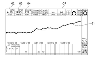
- the display processing unit 41 displays a graph showing the relationship between the parameters calculated by the parameter calculation unit 46 and the elapsed time, and the parameters calculated by the parameter calculation unit 46 on the external monitor 16.
- a graph 61 showing the relationship between the parameter calculated by the parameter calculation unit 46 and the elapsed time is displayed.
- the horizontal axis of the graph 61 shown in FIG. 10 represents the elapsed time (for example, date and time) since the extracorporeal circulation device 1 was attached to the patient P.
- the vertical axis of the graph 61 shown in FIG. 10 represents the parameters calculated by the parameter calculation unit 46.
- the parameters calculated by the parameter calculation unit 46 are calculated using, for example, the following formula, and the withdrawal reference flow rate and the measured blood flow rate at the same rotation speed of the centrifugal pump 3 It is displayed on the external monitor 16 as a difference parameter representing the difference.
- Parameter CP (0.0071 x MF-2.7) x 90 ... Equation (1)
- the parameter CP corresponds to the difference DY between the intercept of the flow rate axis (Y axis) of the line FR2 and the intercept of the flow rate axis (Y axis) of the line FR1 as described above with respect to FIG.
- the symbol “M” in the formula (1) represents the rotation speed of the centrifugal pump 3 received from the centrifugal pump 3 by the communication unit 53.
- the symbol “F” in the formula (1) represents the measured blood flow rate determined by the measured blood flow rate determining unit 45.
- the numerical value "0.0071” in the equation (1) corresponds to the slope of the regression line (line FR1, line FR2) described above with respect to FIG. As described above with respect to FIG. 9, the slope of the regression line (line FR1, line FR2), that is, the numerical value "0.0071” in the equation (1) is limited to 0.0071 (L / min / rpm). is not. Further, the numerical values "2.7" and “90” in the equation (1) are numerical values for convenience for easily grasping or identifying the parameter CP, and may be appropriately set in consideration of "weight” and the like. ..
- the cardiac function of the patient P is restored, and the blood returned into the body of the patient P by the centrifugal pump 3 tends to be pushed back by the blood pumped from the heart P1 of the patient P.
- the parameter CP calculated by the equation (1) is set to increase as the temperature becomes stronger. That is, the graph 61 shown in FIG. 10 shows how the cardiac function of patient P is recovering with the elapsed time.
- the parameter CP calculated by the parameter calculation unit 46 is displayed as a numerical value on the external monitor 16.
- the surgeon or the like can intuitively grasp the parameter CP indicating the degree of recovery of the cardiac function of the patient P as a numerical value by checking the external monitor 16.
- the measured blood flow rate (LMP: L / min) 62 determined by the measured blood flow rate determining unit 45 and the centrifugal pump received from the centrifugal pump 3 by the communication unit 53.
- the rotation speed (RPM) 63 of 3 and the Index (L / min / m2) 64 indicating the flow rate of blood per body surface of the patient P are displayed on the external monitor 16.
- step S18 the withdrawal timing determination unit 47 determines the withdrawal timing of the extracorporeal circulation device 1 based on the parameters calculated by the parameter calculation unit 46 and indicating the comparison between the withdrawal reference flow rate and the measured blood flow rate. To do. That is, the withdrawal timing determination unit 47 determines whether or not the withdrawal timing of the extracorporeal circulatory device 1 is appropriate. For example, as shown by arrow A5 shown in FIG. 9, a mark (circular mark in FIG. 9) indicating the relationship between the rotation speed of the centrifugal pump 3 and the measured flow rate is a line as an approximate line regarding the withdrawal reference flow rate characteristic.
- the withdrawal timing determination unit 47 determines that the withdrawal timing of the extracorporeal circulation device 1 is appropriate. For example, in the first specific example described above with respect to FIG. 9, in the detachment timing determination unit 47, the difference DY between the intercept of the flow rate axis (Y axis) of the line FR2 and the intercept of the flow rate axis (Y axis) of the line FR1 is a predetermined value. When it becomes the following, it is judged that the timing of withdrawal of the extracorporeal circulation device 1 is appropriate. Further, for example, in the second specific example described above with respect to FIG. 10, when the parameter CP calculated by the parameter calculation unit 46 exceeds a predetermined value, the withdrawal timing determination unit 47 determines the withdrawal timing of the extracorporeal circulation device 1. Judge that there is.
- step S19 the notification processing unit 42 indicates to the external monitor 16 that the timing of withdrawal of the extracorporeal circulatory device 1 is appropriate.
- the notification processing unit 42 determines the relationship between the rotation speed of the centrifugal pump 3 and the measured blood flow rate. A blue-based color such as blue or green is added to the representative mark (circular mark in FIG. 9). Further, for example, in the second specific example described above with respect to FIG.
- the notification processing unit 42 determines the parameters and the elapsed time calculated by the parameter calculation unit 46.
- the graph 61 showing the relationship between the above and the parameter CP calculated by the parameter calculation unit 46 are colored with a blue system such as blue or green.
- the notification processing unit 42 indicates that the timing of withdrawal of the extracorporeal circulation device 1 is appropriate by using characters, figures, symbols, or the like. It may be displayed in a pop-up. Alternatively, the notification processing unit 42 may notify by voice when the timing of withdrawal of the extracorporeal circulation device 1 is appropriate.
- step S18 if the timing of withdrawal of the extracorporeal circulatory device 1 is not appropriate (step S18: NO), the above-mentioned process is executed with respect to step S11.
- step S20 following step S19 the control unit 40 determines whether or not the extracorporeal circulatory device 1 has been withdrawn from the patient P.
- step S20: YES the control unit 40 ends the operation of the cardiac function measuring system 10.
- step S21 the control unit 40 notifies that the timing of withdrawal of the extracorporeal circulatory device 1 is appropriate. It is determined whether or not a predetermined time has elapsed since the unit 42 notified the external monitor 16. For example, the control unit 40 uses the timer function of the control unit 40 to measure the time elapsed since the notification processing unit 42 notifies the external monitor 16 that the timing of withdrawal of the extracorporeal circulation device 1 is appropriate. To do.
- the notification processing unit 42 When a predetermined time has elapsed after the notification processing unit 42 notifies the external monitor 16 that the timing of withdrawal of the extracorporeal circulation device 1 is appropriate (step S21: YES), the notification processing unit 42 in step S22. Notifies the external monitor 16 that the timing of withdrawing the extracorporeal circulatory device 1 from the patient P is late. For example, the notification processing unit 42 pops up and displays on the external monitor 16 using characters, figures, symbols, and the like that the timing of leaving the extracorporeal circulatory device 1 from the patient P is late. Alternatively, the notification processing unit 42 may notify by voice that the timing of withdrawing the extracorporeal circulation device 1 from the patient P is late.
- step S21 if a predetermined time has not elapsed since the notification processing unit 42 notified the external monitor 16 that the timing of withdrawal of the extracorporeal circulatory device 1 was appropriate (step S21: NO), the present invention relates to step S20. The above-mentioned process is executed.
- the parameter calculation unit 46 uses a relatively simple mathematical formula or a table or the like as a parameter indicating a comparison between the withdrawal reference flow rate and the measured flow rate. It is possible to calculate a difference parameter representing the difference between the withdrawal reference flow rate and the measured flow rate. Then, the withdrawal timing determination unit 47 can quantitatively determine whether or not the withdrawal timing of the extracorporeal circulatory device 1 is appropriate. That is, the cardiac function measuring system 10 can quantitatively measure the patient's cardiac output ability. As a result, the cardiac function measuring system 10 according to the specific example can determine the recovery of the cardiac function of the patient P easily and with high accuracy.
- the measured blood flow rate determined by the measured blood flow rate determining unit 45 is an average flow rate indicating an average value of a plurality of realistic flow rates measured at a predetermined time by the flow rate measuring unit 21, the withdrawal timing is determined.
- the part 47 compares the withdrawal reference flow rate and the measured flow rate with each other, quantitatively measures the pumping ability of the patient P, and extracorporeally, while suppressing the influence of the beat of the heart P1 whose temporal change is relatively large. It is possible to determine the timing of withdrawal of the circulation device 1.
- the cardiac function measuring system 10 according to the specific example can determine the recovery of the cardiac function of the patient P with even higher accuracy.
- the display processing unit 41 displays a graph showing the relationship between the rotation speed of the centrifugal pump 3 and the withdrawal reference flow rate and the measured blood flow rate on the external monitor 16. Further, in the second specific example described above with respect to FIG. 10, the display processing unit 41 externally displays a graph showing the relationship between the parameters calculated by the parameter calculation unit 46 and the elapsed time, and the parameters calculated by the parameter calculation unit 46. Displayed on the monitor 16. According to these, the surgeon or the like can easily compare the withdrawal reference flow rate and the measured blood flow rate by checking the external monitor 16 and visually grasp the withdrawal timing of the extracorporeal circulatory device 1. it can.
- the notification processing unit 42 notifies on the external monitor 16 that the timing of withdrawal of the extracorporeal circulatory device 1 is appropriate.
- the surgeon or the like can easily visually grasp whether or not the timing of withdrawal of the extracorporeal circulatory device 1 is appropriate by checking the notification displayed on the external monitor 16.
- the cardiac function measuring system 10 according to the specific example can prevent the timing of withdrawal of the extracorporeal circulatory device 1 from being too early than the recovery of the cardiac function of the patient P, and the timing of withdrawal of the extracorporeal circulatory device 1. Can efficiently assist in the judgment of.
- the notification processing unit 42 sends the extracorporeal circulation device 1 to the patient.
- the external monitor 16 notifies that the timing of leaving P is late.
- the surgeon or the like can easily visually grasp whether or not the timing of withdrawal of the extracorporeal circulatory device 1 is late by checking the notification displayed on the external monitor 16.
- the cardiac function measurement system 10 according to the specific example can prevent the timing of withdrawal of the extracorporeal circulatory device 1 from being too late for the recovery of the cardiac function of the patient P, and the timing of withdrawal of the extracorporeal circulatory device 1. Can efficiently assist in the judgment of.
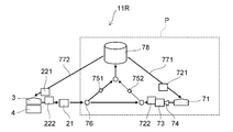
- FIG. 11 is a block diagram illustrating the first circulatory system set in this experiment.
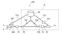
- FIG. 12 is a block diagram illustrating a second circulatory system set in this experiment.
- FIG. 13 is a graph illustrating an example of the relationship between the rotation speed of the centrifugal pump obtained in this experiment and the measured blood flow rate.
- FIG. 14 is a graph illustrating an example of the parameter CP calculated by the parameter calculation unit in this experiment.
- the present inventor uses a tube made of a highly transparent, elastically deformable and flexible synthetic resin such as vinyl chloride resin or silicone rubber to form a blood vessel and circulatory circuit 1R (see FIG. 1) of the human body.
- a simulated circulatory system was set up.
- the arrows shown in each of the first circulatory system 11R shown in FIG. 11 and the second circulatory system 12R shown in FIG. 12 represent the flow of liquid imitating blood, and the blood vessels of the human body, the blood removal side catheter 5, and the blood removal side catheter 5. It represents a blood removal tube 11, a blood feeding tube 12, and a tube imitating a blood feeding side catheter 6.
- each tube is set to about 15 cm or more and 130 cm or less for convenience of experiment. Further, the first circulatory system 11R and the second circulatory system 12R are installed at substantially the same height. As a result, it is not always necessary to consider the drop pressure.
- the pump 71, the first pressure sensor 721, the second pressure sensor 722, the flow rate sensor 73, the check valve 74, and the first clamp 751 are provided in the first circulation system 11R and the second circulation system 12R, respectively.
- the second clamp 752, the branch portion 76, the buffer tank 78, the centrifugal pump 3, the drive motor 4, the third pressure sensor 221 and the fourth pressure sensor 222, and the flow rate measuring unit 21 are provided. ing.
- the pump 71 is a pump that imitates the heart P1 of the patient P, is appropriately controlled to reproduce the beat of the heart P1 of the patient P, and has a relatively high rotation speed (that is, a high discharge pressure) and a relatively low speed. It is driven alternately at a rotation speed (that is, a low discharge pressure).
- a relatively high rotation speed that is, a high discharge pressure
- a relatively low speed that is, a low discharge pressure
- 1000 RPM is set as the high rotation speed of the pump 71
- 800 RPM is set as the low rotation speed of the pump 71.
- 800 RPM is set as the high rotation speed of the pump 71
- 400 RPM is set as the low rotation speed of the pump 71.
- the driving time of the pump 71 at a high rotation speed is 0.5 seconds.
- the driving time of the pump 71 at a low rotation speed is 0.5 seconds. That is, in this experiment, the cycle of the pump 71 is 1 second. In other words, the pump 71 is appropriately controlled to reproduce the beat of the patient P's heart P1 and is driven at a beat rate of 60 bpm.
- the first pressure sensor 721 is installed in a tube 771 that imitates the path of blood from the vena cava to the heart P1 of the patient P, and detects the pressure of the liquid flowing through the tube 771.
- the second pressure sensor 722 detects the pressure of the liquid delivered from the pump 71.
- the flow rate sensor 73 detects the flow rate of the liquid delivered from the pump 71.
- the first clamp 751 is an adjusting device for reproducing the peripheral resistance on the side of the lower limbs of the patient P.
- the second clamp 752 is an adjusting device for reproducing the peripheral resistance of the patient P on the side of the head.
- the bifurcation portion 76 is a portion that imitates the insertion portion of the blood feeding side catheter 6 into the femoral artery.
- the third pressure sensor 221 is installed in a tube 772 that imitates a blood removal tube 11 as a path for blood taken out from the femoral vein of patient P to the centrifugal pump 3, and detects the pressure of the liquid flowing through the tube 772.
- the fourth pressure sensor 222 detects the pressure of the liquid delivered from the centrifugal pump 3.
- the centrifugal pump 3, the drive motor 4, and the flow rate measuring unit 21 are as described above with respect to FIG.
- the present inventor has a flow rate when the rotation speed of the pump 71 is 1000 RPM (that is, the discharge pressure of the pump 71 is about 100 mmHg) in a state where the second clamp 752 is closed.
- the opening degree of the first pump 751 was adjusted so that the measurement result of the sensor 73 was about 4 L / min.
- the present inventor installed the first clamp 751 when the rotation speed of the pump 71 was 1000 RPM (that is, the discharge pressure of the pump 71 was about 100 mmHg).
- the opening degrees of the first clamp 751 and the second clamp 752 were adjusted so that the flow rate of the liquid flowing through each of the tube and the tube in which the second clamp 752 was installed was about 2 L / min.
- the present inventor set the rotation speed of the centrifugal pump 3 in the range of about 600 RPM or more and 1200 RPM or less, and recorded the flow rate value of the liquid sent out from the centrifugal pump 3.
- the recorded flow rate value is an average value of a plurality of measurement data measured by the flow rate measuring unit 21 per second.
- FIG. 13 is a graph obtained as an example of the result of this experiment, in which the rotation speed of the centrifugal pump 3 and the flow rate value of the liquid sent out from the centrifugal pump 3 (that is, measured by the flow rate measuring unit 21 in 1 second). It is a graph exemplifying an example of the relationship with the average value of a plurality of measured data.
- the horizontal axis of the graph shown in FIG. 13 represents the rotation speed (rpm) of the centrifugal pump 3.
- the vertical axis of the graph shown in FIG. 13 represents the flow rate value (L / min) of the liquid delivered from the centrifugal pump 3. That is, the graph shown in FIG. 13 corresponds to the graph described above with respect to FIG. 9.
- the line FR11 shown in FIG. 13 is an example of the experimental result of the pattern assuming that the heart of the patient P is healthy and strong in the first circulatory system 11R.
- the line FR12 shown in FIG. 13 is an example of the experimental result of the pattern assuming that the heart of the patient P is not healthy and weak in the first circulatory system 11R.
- the line FR21 shown in FIG. 13 is an example of the experimental result of the pattern assuming that the heart of the patient P is healthy and strong in the second circulatory system 12R.
- the line FR22 shown in FIG. 13 is an example of the experimental result of the pattern assuming that the heart of the patient P is not healthy and weak in the second circulatory system 12R.
- the lines FR11 and FR21 of the experimental results of the pattern assuming that the heart of the patient P is healthy and strong are the patients P. It is located below the lines FR12 and FR22 of the experimental results of the pattern assuming that the heart is weak rather than healthy. That is, as shown by the arrow shown in FIG. 13, when the cardiac function of the patient P is restored, the relationship between the rotation speed of the centrifugal pump 3 and the flow rate value of the liquid delivered from the centrifugal pump 3 moves downward. As a result, as described above with respect to FIG. 9, when the cardiac function of the patient P is restored, the relationship between the rotation speed of the centrifugal pump 3 and the measured flow rate moves downward, and a line as an approximate line regarding the withdrawal reference flow rate characteristic. It was confirmed in this experiment that it approaches FR1.
- FIG. 14 is a graph illustrating an example of the parameter CP in each assumed pattern of this experiment.
- the horizontal axis of the graph shown in FIG. 14 represents the assumed pattern of this experiment.
- the vertical axis of the graph shown in FIG. 14 represents the parameter CP calculated by the parameter calculation unit 46.
- the parameter CP is as described above with respect to FIG. 10, and is, for example, a parameter calculated using the equation (1).
- the parameter CP shown in FIG. 14 is the average of the plurality of values calculated by the equation (1) based on the plurality of rotation speeds of the centrifugal pump 3 and the plurality of flow rate values of the liquid delivered from the centrifugal pump 3. The value.
- the parameter CP of the pattern 11R1 assuming that the heart of the patient P is healthy and strong in the first circulatory system 11R is calculated based on the seven measurement data (rotation speed and flow rate) on the line FR11 shown in FIG. It is the average value of multiple values.
- the parameter CP of the pattern 11R2, which assumes the case where the heart of the patient P is not healthy and weak in the first circulatory system 11R, is the average of a plurality of values calculated based on the five measurement data on the line FR12 shown in FIG. The value.
- the parameter CP of the pattern 12R1 assuming that the heart of the patient P is healthy and strong in the second circulatory system 12R is the average value of a plurality of values calculated based on the eight measurement data on the line FR21 shown in FIG. Is.
- the parameter CP of the pattern 12R2 assuming that the heart of the patient P is not healthy and weak is the average of a plurality of values calculated based on the six measurement data on the line FR22 shown in FIG. The value.
- the parameter CP of the patterns 11R1 and 12R1 assuming that the heart of the patient P is healthy and strong is the heart of the patient P.
- the parameter CP of the patterns 11R2 and 12R2 which is assumed to be weak and not healthy.
- the formula used when calculating the parameter CP is not limited to the above-mentioned formula (1) with respect to FIG. 10, and may be another formula.
- the calculation formula of the parameter CP is appropriately set so that the parameter CP when the heart of the patient P is healthy and strong has a lower correlation than the parameter CP when the heart of the patient P is not healthy and weak. Good.
- 1 Extracorporeal circulation device, 1R: Circulation circuit, 2: Artificial lung, 3: Centrifugal pump, 4: Drive motor, 5: Blood removal side catheter, 6: Blood delivery side catheter, 8, 9: Connector, 10: Cardiac function Measurement system, 11: Blood removal tube, 11R: 1st circulation system, 12: Blood pump tube, 12R: 2nd circulation system, 14: Oxygen supply tube, 16: External monitor, 21: Flow measurement unit, 30: Storage unit , 31: Program, 32: Pump discharge reference flow storage unit, 33: Pump characteristic storage unit, 40: Control unit, 41: Display processing unit, 42: Notification processing unit, 43: Pump discharge pressure determination unit, 44: Pump discharge reference flow rate Decision unit, 45: Measurement pump flow rate determination unit, 46: Parameter calculation unit, 47: Withdrawal timing determination unit, 48: CPU, 49: FPGA, 51: Computer, 52: Touch panel, 53: Communication unit, 61: Graph, 62: Measured blood flow rate, 63: Centrifugal pump rotation speed, 64: Index
Abstract
【課題】患者の心機能の回復を高い精度で判断することができる心機能測定システム、体外循環装置および心機能測定プログラムを提供すること。 【解決手段】心機能測定システム10は、患者Pから血液を取り出すとともに患者Pに血液を戻すポンプ3の回転数を検出し、回転数に基づいてポンプ3の吐出圧を決定し、吐出圧に基づいてポンプ3から送り出される血液の理論的な流量を示す離脱基準流量を決定し、ポンプ3から送り出される血液の流量を測定する流量測定部の測定結果に基づいて血液の現実的な流量を示す測定送血流量を決定し、離脱基準流量と測定送血流量との比較に基づいて体外循環装置1の離脱のタイミングを判断する。
Description
本発明は、心機能測定システム、体外循環装置および心機能測定プログラムに関する。
心原性心停止患者に対する専門的な蘇生治療の一つに、経皮的心肺補助装置として体外循環装置を用いた侵襲的心肺蘇生(Percutaneous Cardiopulmonary Support : PCPS)がある。このような蘇生治療は、体外循環式心肺蘇生(Extracorporeal Cardiopulmonary Resuscitation : ECPR)と呼ばれたり、ECMO(Extracorporeal Membrane Oxygenation)と呼ばれたりすることもある。
体外循環装置を用いた侵襲的心肺蘇生において、患者の心機能(心臓の状態)の回復を判断することは、重要な要素の一つである。すなわち、体外循環装置の離脱のタイミングが患者の心機能の回復よりも早すぎると、患者の心臓が耐えることができず、体外循環装置を再装着する必要性が生じたり、患者が死亡したりすることがある。一方で、体外循環装置の離脱のタイミングが患者の心機能の回復よりも遅すぎると、抗凝固療法や血漿成分などの消耗により、出血などの合併症が生ずることがある。つまり、体外循環装置の離脱については、適正なタイミングが存在する。そして、体外循環装置の離脱のタイミングを早期に見極めることができることが望ましい。
体外循環装置を用いた侵襲的心肺蘇生の最中において、体外循環装置のポンプは、患者から血液を取り出し、人工肺を通過させ、人工肺を通過した血液を患者に戻す。このとき、ポンプにより患者の体内に戻された血液の流れの方向は、患者の体内を流れている血液の流れの方向とは逆である。つまり、ポンプは、人工肺を通過した血液を、逆行性を有する状態で患者に戻す。そのため、カテーテルに装着された流量センサが患者の心臓の近傍に送達された場合であっても、心臓のみの拍出量を測定することは困難である。そのため、この場合には、患者の心機能の回復を高い精度で判断することは困難である。
また、体外循環装置を用いた侵襲的心肺蘇生の最中において、カテーテルに装着された流量センサを患者の心臓の近傍に送達させない施設も比較的多い。そのため、この場合においても、患者の心機能の回復を高い精度で判断することは困難である。また、心機能の回復を判断するために、体外循環装置の動作を一旦停止させ、心臓の拍出量を測定する施設も存在する。しかし、患者に与える負担を軽減するためには、断続的でなく継続的に心機能の回復を判断できることが望ましい。
特許文献1には、血液流量計で測定した血液流量の時間微分を演算し、その演算結果に基づいて心機能を評価する心機能評価装置が開示されている。特許文献1に記載された心機能評価装置は、血液流量の時間微分を血圧の時間微分に換算している。血液流量の時間微分と血圧の時間微分との関係は、特許文献1の図2に記載されている。特許文献1に記載された図2によれば、血液流量計を含む心機能評価ブロックが患者の心臓の近傍に設けられているにもかかわらず、血圧の時間微分の誤差が比較的大きい。そのため、前述したように、血液流量計が患者の心臓の近傍に設けられた場合であっても、患者の心機能の回復を高い精度で判断することは困難である。
本発明は、前記課題を解決するためになされたものであり、患者の心機能の回復を高い精度で判断することができる心機能測定システム、体外循環装置および心機能測定プログラムを提供することを目的とする。
前記課題は、体外循環装置に設置され患者の心機能を測定する心機能測定システムであって、前記患者から血液を取り出すとともに前記患者に前記血液を戻すポンプの回転数を検出し、前記回転数に基づいて前記ポンプの吐出圧を決定し、前記吐出圧に基づいて前記ポンプから送り出される前記血液の理論的な流量を示す離脱基準流量を決定し、前記体外循環装置の循環回路を流れる前記血液の流量を測定する流量測定部の測定結果に基づいて前記血液の現実的な流量を示す測定送血流量を決定し、前記離脱基準流量と前記測定送血流量との比較に基づいて前記体外循環装置の離脱のタイミングを判断することを特徴とする本発明に係る心機能測定システムにより解決される。
これによれば、本発明に係る心機能測定システムは、ポンプの回転数に基づいて決定されたポンプの吐出圧に基づいて、ポンプから送り出される血液の理論的な流量を示す離脱基準流量を決定する。また、心機能測定システムは、体外循環装置の循環回路を流れる血液の流量を測定する流量測定部の測定結果に基づいて、血液の現実的な流量を示す測定送血流量を決定する。そして、心機能測定システムは、離脱基準流量と測定送血流量との比較に基づいて体外循環装置の離脱のタイミングを判断する。このように、本発明に係る心機能測定システムは、離脱基準流量と、時間的変化が比較的少ない測定送血流量と、を互いに比較し、体外循環装置の離脱のタイミングを判断する。これにより、本発明に係る心機能測定システムは、患者の心機能の回復を高い精度で判断することができる。
本発明に係る心機能測定システム、好ましくは、前記離脱基準流量と前記測定送血流量との比較を示すパラメータを算出し、前記パラメータに基づいて前記体外循環装置の離脱のタイミングを判断することを特徴とする。
本発明に係る心機能測定システムによれば、離脱基準流量と測定送血流量との比較を示すパラメータを算出することにより、患者の拍出能力を定量的に測定し、体外循環装置の離脱のタイミングを定量的な比較に基づいて判断することができる。これにより、本発明に係る心機能測定システムは、患者の心機能の回復を高い精度で判断することができる。
本発明に係る心機能測定システムにおいて、好ましくは、前記パラメータは、前記離脱基準流量と前記測定送血流量との差分を表す差分パラメータであることを特徴とする。
これによれば、本発明に係る心機能測定システムは、比較的簡易的な数式あるいはテーブル等を用いることにより、離脱基準流量と測定送血流量との比較を示すパラメータとして、離脱基準流量と測定送血流量との差分を表す差分パラメータを算出し、患者の拍出能力を定量的に測定することができる。これにより、本発明に係る心機能測定システムは、患者の心機能の回復を簡易的かつ高い精度で判断することができる。
本発明に係る心機能測定システムは、好ましくは、前記パラメータと経過時間との関係を表すグラフ、および前記パラメータを表示部に表示することを特徴とする。
本発明に係る心機能測定システムによれば、術者等は、表示部を確認することにより、離脱基準流量と測定送血流量とを容易に比較し、体外循環装置の離脱のタイミングを視覚的に把握することができる。
本発明に係る心機能測定システムは、好ましくは、前記回転数と、前記離脱基準流量および前記測定送血流量と、の関係を表すグラフを表示部に表示することを特徴とする。
本発明に係る心機能測定システムによれば、術者等は、表示部を確認することにより、離脱基準流量と測定送血流量とを容易に比較し、体外循環装置の離脱のタイミングを視覚的に把握することができる。
本発明に係る心機能測定システムは、好ましくは、前記離脱のタイミングが適正になると、前記離脱のタイミングが適正であることを前記表示部において報知することを特徴とする。
本発明に係る心機能測定システムによれば、術者等は、表示部に表示された報知を確認することにより、体外循環装置の離脱のタイミングが適正であるか否かを視覚的に容易に把握することができる。これにより、本発明に係る心機能測定システムは、体外循環装置の離脱のタイミングが患者の心機能の回復よりも早すぎることを抑えることができ、体外循環装置の離脱のタイミングの判断を効率的に補助することができる。
本発明に係る心機能測定システムは、好ましくは、前記離脱のタイミングが適正であることを前記表示部において報知してから所定時間が経過すると、前記離脱のタイミングが遅いことを前記表示部において報知することを特徴とする。
本発明に係る心機能測定システムによれば、術者等は、表示部に表示された報知を確認することにより、体外循環装置の離脱のタイミングが遅いか否かを視覚的に容易に把握することができる。これにより、本発明に係る心機能測定システムは、体外循環装置の離脱のタイミングが患者の心機能の回復よりも遅すぎることを抑えることができ、体外循環装置の離脱のタイミングの判断を効率的に補助することができる。
本発明に係る心機能測定システムにおいて、好ましくは、前記測定送血流量は、流量測定部により所定時間に測定された複数の前記現実的な流量の平均値を示す平均流量であることを特徴とする。
これによれば、本発明に係る心機能測定システムは、時間的変化が比較的大きい心臓の拍動による影響を抑えつつ、離脱基準流量と測定送血流量とを互いに比較し、患者の拍出能力を定量的に測定し、体外循環装置の離脱のタイミングを判断することができる。これにより、本発明に係る心機能測定システムは、患者の心機能の回復をより一層高い精度で判断することができる。
前記課題は、循環回路を用いて血液を体外循環させる体外循環装置であって、一部が患者に挿入され前記患者から取り出された前記血液を導く脱血側カテーテルと、前記患者から血液を取り出すとともに前記患者に前記血液を戻すポンプと、前記ポンプよりも下流側に設けられるとともに一部が前記患者に挿入され前記ポンプから送り出された前記血液を前記患者に導く送血側カテーテルと、前記循環回路に設けられ前記循環回路を流れる前記血液の流量を測定する流量測定部と、上記のいずれかの心機能測定システムと、を備えたことを特徴とする本発明に係る体外循環装置により解決される。
本発明に係る体外循環装置によれば、心機能測定システムは、ポンプの回転数に基づいて決定されたポンプの吐出圧に基づいて、ポンプから送り出される血液の理論的な流量を示す離脱基準流量を決定する。また、心機能測定システムは、体外循環装置の循環回路を流れる血液の流量を測定する流量測定部の測定結果に基づいて、血液の現実的な流量を示す測定送血流量を決定する。そして、心機能測定システムは、離脱基準流量と測定送血流量との比較に基づいて体外循環装置の離脱のタイミングを判断する。このように、心機能測定システムは、離脱基準流量と、時間的変化が比較的少ない測定送血流量と、を互いに比較し、体外循環装置の離脱のタイミングを判断する。これにより、本発明に係る心体外循環装置は、患者の心機能の回復を高い精度で判断することができる。
前記課題は、体外循環装置に設置され患者の心機能を測定する心機能測定システムのコンピュータによって実行される心機能測定プログラムであって、前記コンピュータに、前記患者から血液を取り出すとともに前記患者に前記血液を戻すポンプの回転数を検出し、前記回転数に基づいて前記ポンプの吐出圧を決定し、前記吐出圧に基づいて前記ポンプから送り出される前記血液の理論的な流量を示す離脱基準流量を決定し、前記体外循環装置の循環回路を流れる前記血液の流量を測定する流量測定部の測定結果に基づいて前記血液の現実的な流量を示す測定送血流量を決定し、前記離脱基準流量と前記測定送血流量との比較に基づいて前記体外循環装置の離脱のタイミングを判断するステップを実行させることを特徴とする本発明に係る心機能測定プログラムにより解決される。
これによれば、本発明に係る心機能測定プログラムは、ポンプの回転数に基づいて決定されたポンプの吐出圧に基づいて、ポンプから送り出される血液の理論的な流量を示す離脱基準流量を決定させる。また、心機能測定プログラムは、体外循環装置の循環回路を流れる血液の流量を測定する流量測定部の測定結果に基づいて、血液の現実的な流量を示す測定送血流量を決定させる。そして、心機能測定プログラムは、離脱基準流量と測定送血流量との比較に基づいて体外循環装置の離脱のタイミングを判断させる。このように、心機能測定プログラムは、離脱基準流量と、時間的変化が比較的少ない測定送血流量と、を互いに比較させ、体外循環装置の離脱のタイミングを判断させる。これにより、本発明に係る心機能測定プログラムによれば、患者の心機能の回復を高い精度で判断することができる。
本発明によれば、患者の心機能の回復を高い精度で判断することができる心機能測定システム、体外循環装置および心機能測定プログラムを提供することができる。
以下に、本発明の好ましい実施形態を、図面を参照して詳しく説明する。
なお、以下に説明する実施形態は、本発明の好適な具体例であるから、技術的に好ましい種々の限定が付されているが、本発明の範囲は、以下の説明において特に本発明を限定する旨の記載がない限り、これらの態様に限られるものではない。また、各図面中、同様の構成要素には同一の符号を付して詳細な説明は適宜省略する。
なお、以下に説明する実施形態は、本発明の好適な具体例であるから、技術的に好ましい種々の限定が付されているが、本発明の範囲は、以下の説明において特に本発明を限定する旨の記載がない限り、これらの態様に限られるものではない。また、各図面中、同様の構成要素には同一の符号を付して詳細な説明は適宜省略する。
図1は、本発明の実施形態に係る体外循環装置を表す概略図である。
図1に示す体外循環装置1が行う「体外循環」には、「体外循環動作」と、「補助循環動作」と、が含まれる。体外循環装置1は、「体外循環動作」と「補助循環動作」とのいずれも行うことができる。
図1に示す体外循環装置1が行う「体外循環」には、「体外循環動作」と、「補助循環動作」と、が含まれる。体外循環装置1は、「体外循環動作」と「補助循環動作」とのいずれも行うことができる。
「体外循環動作」とは、例えば心臓外科手術によって一時的に心臓における血液循環が停止されるような場合に、血液の循環動作と、血液に対するガス交換動作(酸素付加および/または二酸化炭素除去)と、が体外循環装置1により行われることをいう。
また、「補助循環動作」とは、体外循環装置1の適用対象である患者Pの心臓が十分な機能を果たせない場合や、肺によるガス交換が十分に行えないような状態において、血液の循環動作と、血液に対するガス交換動作と、が体外循環装置1によっても行われることをいう。本実施形態の説明では、主として「補助循環動作」を例に挙げる。
また、「補助循環動作」とは、体外循環装置1の適用対象である患者Pの心臓が十分な機能を果たせない場合や、肺によるガス交換が十分に行えないような状態において、血液の循環動作と、血液に対するガス交換動作と、が体外循環装置1によっても行われることをいう。本実施形態の説明では、主として「補助循環動作」を例に挙げる。
例えば、体外循環装置1は、患者Pの心臓が正常に動作しない場合や、患者Pの心臓は正常に動作するものの肺が正常に動作しない場合などに適用される。ところで、図1に示す体外循環装置1は、例えば患者Pの心臓外科手術を行う場合やその後のICUにおける治療等で用いられる。図1に示す体外循環装置1は、体外循環装置1のポンプを作動して患者の静脈から脱血して、人工肺により血液中のガス交換を行って血液の酸素化を行った後に、酸素化が行われた血液を再び患者の動脈もしくは静脈に戻す人工肺体外血液循環を行うことができる。このように、体外循環装置1は、心臓と肺の代行を行う装置である。
図1に示すように、体外循環装置1は、血液を循環させる循環回路1Rを有している。循環回路1Rは、人工肺2と、遠心ポンプ3と、遠心ポンプ3を駆動するドライブモータ4と、脱血側カテーテル(静脈側カテーテル)5と、送血側カテーテル(動脈側カテーテル)6と、心機能測定システム10と、を有している。本実施形態の遠心ポンプ3は、本発明の「ポンプ」の一例である。心機能測定システム10は、制御部40を有し、体外循環装置1のコントローラとして設けられている。なお、遠心ポンプ3は、血液ポンプなどとも呼ばれ、遠心式以外のポンプであってもよい。
脱血側カテーテル5は、静脈側カニューレ(脱血側カニューレ)などとも呼ばれ、大腿静脈より挿入される。脱血側カテーテル5の先端は、右心房に留置される。脱血側カテーテル5は、コネクタ8を介して脱血チューブ(脱血ラインともいう)11に接続されるとともに、脱血チューブ11を介して遠心ポンプ3に接続され、患者Pから取り出された血液を脱血チューブ11を介して遠心ポンプ3に導く。脱血チューブ11は、脱血側カテーテル5と遠心ポンプ3とを接続する管路であり、脱血側カテーテル5を介して患者Pから取り出された血液を遠心ポンプ3へ導く管路である。
送血側カテーテル6は、動脈側カニューレ(送血側カニューレ)などとも呼ばれ、大腿動脈より挿入される。送血側カテーテル6は、コネクタ9を介して送血チューブ(送血ラインともいう)12に接続されるとともに、送血チューブ12を介して人工肺2に接続され、人工肺2を通過した血液を送血チューブ12を介して患者Pに導く。送血チューブ12は、人工肺2と送血側カテーテル6とを接続する管路であり、人工肺2を通過した血液を患者Pに導く管路である。
ドライブモータ4は、心機能測定システム10の指令SGに基づいて遠心ポンプ3の駆動を制御する。遠心ポンプ3は、脱血側カテーテル5よりも下流側に設けられ、ドライブモータ4から伝達された駆動力を受けて駆動する。遠心ポンプ3は、脱血側カテーテル5および脱血チューブ11を介して患者Pから血液を取り出し、人工肺2へ送り出した後、送血チューブ12および送血側カテーテル6を介して患者Pに血液を戻す。また、遠心ポンプ3は、遠心ポンプ3の回転数に関する信号Gを心機能測定システム10に送信する。
人工肺2は、遠心ポンプ3よりも下流側に設けられている。具体的には、人工肺2は、遠心ポンプ3と送血チューブ12との間に配置されている。人工肺2は、血液に対するガス交換動作(酸素付加および/または二酸化炭素除去)を行う。人工肺2は、例えば膜型人工肺であるが、特に好ましくは中空糸膜型人工肺である。人工肺2には、酸素ガスが酸素供給チューブ14を通じて供給される。
脱血チューブ11および送血チューブ12としては、例えば塩化ビニル樹脂やシリコーンゴム等の透明性の高い、弾性変形可能な可撓性を有する合成樹脂製の管路が使用される。液体である血液は、脱血チューブ11内ではV1方向およびV2方向に流れ、送血チューブ12内ではV3方向に流れる。
心機能測定システム10は、各種情報を取得し演算を行うとともに、ドライブモータ4および外部モニタ16などの機器の動作を制御する制御信号を生成し、各機器に送信する。言い換えれば、心機能測定システム10は、体外循環装置1を管理する。心機能測定システム10の詳細については、後述する。また、心機能測定システム10は、各種情報を入力可能な入力部であると共に各種情報を表示する表示部としてのタッチパネル52(図5参照)を有していてもよい。つまり、本発明の「表示部」は、心機能測定システム10とは別体として設けられた外部モニタ16であってもよく、心機能測定システム10が有するタッチパネル52であってもよい。タッチパネル52は、術者等の指の接触等を検出可能とされている。
本実施形態に係る体外循環装置1は、流量測定部21と、外部モニタ(表示部)16と、をさらに備える。本実施形態の外部モニタ16は、本発明の「表示部」の一例である。以下の説明では、本発明の「表示部」が外部モニタ16である場合を例に挙げる。
流量測定部21は、循環回路1Rに設けられている。本実施形態に係る体外循環装置1では、流量測定部21は、人工肺2と送血側カテーテル6との間における循環回路1Rに設けられている。具体的には、流量測定部21は、送血チューブ12に設けられている。流量測定部21は、送血チューブ12に設けられることにより、患者Pに戻される直前の血液の流量を測定することができ、患者Pに比較的近い位置において循環回路1Rを流れる血液の流量を測定することができる。但し、流量測定部21の設置位置は、送血チューブ12に限定されるわけではなく、循環回路1Rのいずれの箇所であってもよい。以下の説明では、流量測定部21が送血チューブ12に設けられた場合を例に挙げる。
流量測定部21は、例えば流量センサであり、循環回路1Rの内部を流れる血液の流量を検知する。図1に表した流量測定部21は、遠心ポンプ3から送り出される血液の流量を測定する。流量測定部21は、循環回路1Rの内部を流れる血液の流量に関する信号S1を心機能測定システム10に送信する。本実施形態では、流量測定部21は、遠心ポンプ3から送り出される血液の流量に関する信号S1を心機能測定システム10に送信する。流量測定部21としては、例えば超音波流量計が挙げられる。超音波流量計としては、例えば超音波伝搬時間差方式の流量計が用いられる。但し、流量測定部21は、超音波流量計に限定されるわけではない。
図2は、体外循環装置から患者に戻される血液の流れおよび患者の心臓から送り出される血液の流れを説明する模式図である。
図3は、本実施形態の制御部および流量測定部を説明するブロック図である。
なお、図3に表したブロック図では、説明の便宜上、人工肺を省略している。
図3は、本実施形態の制御部および流量測定部を説明するブロック図である。
なお、図3に表したブロック図では、説明の便宜上、人工肺を省略している。
図2に表した矢印A1および図3に表した矢印A3のように、遠心ポンプ3から送血チューブ12および送血側カテーテル6を介して患者Pに戻される血液は、例えば動脈を通り患者Pの心臓P1に向かって流れる。一方で、図2に表した矢印A2および図3に表した矢印A4のように、患者Pの心臓P1から送り出され患者Pの肺で酸素化された血液は、動脈を通り頭部の末梢血管および下肢の末梢血管に向かって流れる。
このように、遠心ポンプ3により患者Pの体内に戻された血液の流れの方向は、患者Pの体内を流れている血液の流れの方向とは逆である。つまり、遠心ポンプ3は、人工肺2を通過した血液を、逆行性を有する状態で患者Pに戻す。
図3に表したように、心機能測定システム10の制御部40は、CPU(central processing unit)48と、FPGA(field programmable gate array)49と、を有する。例えば、CPU48は、遠心ポンプ3から送り出される血液の流量の測定を要求する信号S2を50ミリ秒(ms)ごとにFPGA49に送信する。FPGA49は、CPU48から送信された信号S2を受信し、遠心ポンプ3から送り出される血液の流量の測定を要求する信号S3を50msごとに流量測定部21に送信する。流量測定部21は、FPGA49から送信された信号S3を受信し、遠心ポンプ3から送り出される血液の流量を50msごとに測定するとともに、測定した血液の流量に関する信号S4をFPGA49に送信する。FPGA49は、流量測定部21から送信された信号S4を受信し、直近の1秒間における流量の平均値に関する信号S5をCPU48に送信する。
本実施形態では、流量測定部21が50msごとに血液の流量を測定し、測定した血液の流量に関する信号S4をFPGA49に送信するため、1秒間あたり20個(1s/50ms)の測定データが存在する。そこで、FPGA49は、直近の1秒間における流量の平均値として、20個の測定データの平均値を算出し、流量の平均値に関する信号S5をCPU48に送信する。CPU48は、FPGA49から送信された信号S5を受信し、遠心ポンプ3から送り出される血液の流量を測定送血流量として外部モニタ(表示部)16に表示させる制御を実行する。本実施形態では、測定送血流量は、直近の1秒間における流量の平均値、すなわち20個の測定データの平均値である。
なお、流量測定部21が血液の流量を測定する周期は、50msに限定されるわけではない。また、CPU48が血液の流量の平均値を算出する際の所定時間は、1秒間に限定されるわけではない。
図4は、本実施形態に係る心機能測定システムの要部構成を表すブロック図である。
本実施形態に係る心機能測定システム10は、コンピュータ51と、記憶部30と、を有する。コンピュータ51は、制御部40(図1および図5参照)を有し、記憶部30に記憶されたプログラム31を読み出して種々の演算や処理を実行する。記憶部30は、コンピュータ51によって実行されるプログラム31(心機能測定プログラム)を格納する。本実施形態のプログラム31は、本発明の「心機能測定プログラム」の一例である。記憶部30としては、例えばハードディスクドライブ(HDD:Hard Disk Drive)などが挙げられる。なお、プログラム31は、記憶部30に格納されていることには限定されず、コンピュータ読み取り可能な記憶媒体に予め格納され頒布されてもよく、あるいはネットワークを介して心機能測定システム10にダウンロードされてもよい。また、記憶部30は、コンピュータ51に接続された外部の記憶装置であってもよい。
本実施形態に係る心機能測定システム10は、コンピュータ51と、記憶部30と、を有する。コンピュータ51は、制御部40(図1および図5参照)を有し、記憶部30に記憶されたプログラム31を読み出して種々の演算や処理を実行する。記憶部30は、コンピュータ51によって実行されるプログラム31(心機能測定プログラム)を格納する。本実施形態のプログラム31は、本発明の「心機能測定プログラム」の一例である。記憶部30としては、例えばハードディスクドライブ(HDD:Hard Disk Drive)などが挙げられる。なお、プログラム31は、記憶部30に格納されていることには限定されず、コンピュータ読み取り可能な記憶媒体に予め格納され頒布されてもよく、あるいはネットワークを介して心機能測定システム10にダウンロードされてもよい。また、記憶部30は、コンピュータ51に接続された外部の記憶装置であってもよい。
次に、本実施形態に係る心機能測定システム10の要部構成を、図面を参照してさらに説明する。
図5は、本実施形態に係る心機能測定システムの要部構成を表すブロック図である。
図5は、本実施形態に係る心機能測定システムの要部構成を表すブロック図である。
本実施形態に係る心機能測定システム10は、制御部40と、記憶部30と、タッチパネル52と、通信部53と、を有する。制御部40は、記憶部30に記憶されたプログラム31(図4参照)を読み出して種々の演算や処理を実行する。制御部40は、表示処理部41と、報知処理部42と、ポンプ吐出圧決定部43と、離脱基準流量決定部44と、測定送血流量決定部45と、パラメータ算出部46と、離脱タイミング判断部47と、を有する。表示処理部41、報知処理部42、ポンプ吐出圧決定部43、離脱基準流量決定部44、測定送血流量決定部45、パラメータ算出部46、および離脱タイミング判断部47は、記憶部30に格納されているプログラム31をコンピュータ51が実行することにより実現される。なお、表示処理部41、報知処理部42、ポンプ吐出圧決定部43、離脱基準流量決定部44、測定送血流量決定部45、パラメータ算出部46、および離脱タイミング判断部47は、ハードウェアによって実現されてもよく、ハードウェアとソフトウェアとの組み合わせによって実現されてもよい。記憶部30は、図4に関して前述したプログラム31を格納するとともに、離脱基準流量記憶部32と、ポンプ特性記憶部33と、を有する。
表示処理部41は、遠心ポンプ3から送信された回転数に関する信号Gに基づく遠心ポンプ3の回転数と、離脱基準流量決定部44により決定された離脱基準流量と、測定送血流量決定部45により決定された測定送血流量と、パラメータ算出部46により算出されたパラメータと、離脱タイミング判断部47により判断された体外循環装置1の離脱のタイミングと、の少なくともいずれかを外部モニタ16に表示する処理を実行する。本実施形態において、「離脱基準流量」とは、患者Pの心臓が元気で強い場合に遠心ポンプ3の吐出圧に基づいて遠心ポンプ3から送り出される血液の理論的な流量であり、離脱基準流量決定部44により決定される。「測定送血流量」とは、循環回路1Rを流れる血液(本実施形態では遠心ポンプ3から送り出される血液)の現実的な流量であり、流量測定部21の測定結果に基づいて測定送血流量決定部45により決定される。パラメータ算出部46により算出されるパラメータ、および体外循環装置1の離脱のタイミングの詳細については、後述する。
また、後述するように、表示処理部41は、遠心ポンプ3の回転数と、測定送血流量と、の関係を表すグラフを外部モニタ16に表示したり、パラメータ算出部46により算出されたパラメータと、経過時間と、の関係を表すグラフを外部モニタ16に表示したりすることができる。
報知処理部42は、所定の条件が満たされたときに、体外循環装置1の離脱のタイミングが適正であることを外部モニタ16に表示したり、体外循環装置1の離脱のタイミングが遅いことを外部モニタ16に表示したりする処理を実行する。報知処理部42による報知の方法は、例えば光や音の発生により実行されてもよい。
ポンプ吐出圧決定部43は、ポンプ特性記憶部33に記憶された遠心ポンプ3のポンプ特性を参照し、遠心ポンプ3から送信された回転数に関する信号G(すなわち遠心ポンプ3の回転数)に基づいて遠心ポンプ3の吐出圧を決定する。
ここで、図6を参照して、ポンプ特性記憶部33に記憶された遠心ポンプ3のポンプ特性の一例を説明する。
図6は、本実施形態のポンプ特性記憶部に記憶されたポンプ特性の一例を例示するグラフである。
図6は、本実施形態のポンプ特性記憶部に記憶されたポンプ特性の一例を例示するグラフである。
図6に表したグラフの横軸は、遠心ポンプ3から送り出される流量(L/min)を表している。図6に表したグラフの縦軸は、遠心ポンプ3の吐出圧(mmHg)を表している。図6に表したように、遠心ポンプ3の流量と、遠心ポンプ3の吐出圧と、の関係は、遠心ポンプ3の回転数ごとの曲線あるいは直線として表される。遠心ポンプ3の吐出圧は、遠心ポンプ3の流量が増加するとわずかに低下するものの、遠心ポンプ3の回転数が同じである場合において遠心ポンプ3の流量によってはあまり変化せず略一定である。
例えば、遠心ポンプ3の回転数が1000rpmである場合において、遠心ポンプ3の流量が2L/minであるときには、遠心ポンプ3の吐出圧は、約100mmHg程度である。例えば、遠心ポンプ3の回転数が2000rpmである場合において、遠心ポンプ3の流量が2L/minであるときには、遠心ポンプ3の吐出圧は、約400mmHg程度である。例えば、遠心ポンプ3の回転数が3000rpmである場合において、遠心ポンプ3の流量が2L/minであるときには、遠心ポンプ3の吐出圧は、約900mmHg程度である。このように、図6に表したポンプ特性の一例では、遠心ポンプ3の回転数が2倍になると遠心ポンプ3の吐出圧が約4倍になり、遠心ポンプ3の回転数が3倍になると遠心ポンプ3の吐出圧が約9倍になる。つまり、図6に表したポンプ特性の一例では、遠心ポンプ3の吐出圧は、遠心ポンプ3の回転数の2乗に略比例する。
このようにして、ポンプ吐出圧決定部43は、ポンプ特性記憶部33に記憶された遠心ポンプ3のポンプ特性を参照し、遠心ポンプ3の回転数に基づいて遠心ポンプ3の吐出圧を決定する。
なお、ポンプ特性記憶部33に記憶された遠心ポンプ3のポンプ特性は、図6に表したグラフだけに限定されるわけではなく他のグラフであってもよい。その場合、遠心ポンプのポンプ特性として、遠心ポンプの種類によっては、流量の変化に対する吐出圧の変化が比較的大きい遠心ポンプがある。したがって、このような遠心ポンプ3が用いられる場合、ポンプ吐出圧決定部43は、遠心ポンプ3から送信された回転数に関する信号Gに加えて、流量測定部21から送信された信号S4あるいは測定送血流量決定部45により決定された測定送血流量に基づいて遠心ポンプ3の吐出圧を決定することができる。また、ポンプ特性記憶部33に記憶された遠心ポンプ3のポンプ特性は、遠心ポンプ3の回転数と遠心ポンプ3の吐出圧との関係を表すグラフだけに限定されるわけではなく、例えば遠心ポンプ3の回転数と遠心ポンプ3の吐出圧との関係を表す数式であってもよく、遠心ポンプ3の回転数と遠心ポンプ3の吐出圧との関係を表す表(テーブル)であってもよい。
続いて、図5に戻り、本実施形態に係る心機能測定システム10の要部構成をさらに説明する。
離脱基準流量決定部44は、離脱基準流量記憶部32に記憶された離脱基準流量特性を参照し、ポンプ吐出圧決定部43により決定された遠心ポンプ3の吐出圧に基づいて、遠心ポンプ3から送り出される血液の理論的な流量を示す離脱基準流量を決定する。離脱基準流量記憶部32に記憶された離脱基準流量特性は、患者Pの心臓が元気で強い場合において、遠心ポンプ3の吐出圧または回転数と、遠心ポンプ3の流量と、の関係を表す。例えば、離脱基準流量記憶部32に記憶された離脱基準流量特性は、患者Pの心臓が元気で強い場合において、遠心ポンプ3の吐出圧または回転数と、遠心ポンプ3の流量と、の関係を表すグラフや数式や表(テーブル)などである。
離脱基準流量決定部44は、離脱基準流量記憶部32に記憶された離脱基準流量特性を参照し、ポンプ吐出圧決定部43により決定された遠心ポンプ3の吐出圧に基づいて、遠心ポンプ3から送り出される血液の理論的な流量を示す離脱基準流量を決定する。離脱基準流量記憶部32に記憶された離脱基準流量特性は、患者Pの心臓が元気で強い場合において、遠心ポンプ3の吐出圧または回転数と、遠心ポンプ3の流量と、の関係を表す。例えば、離脱基準流量記憶部32に記憶された離脱基準流量特性は、患者Pの心臓が元気で強い場合において、遠心ポンプ3の吐出圧または回転数と、遠心ポンプ3の流量と、の関係を表すグラフや数式や表(テーブル)などである。
離脱基準流量記憶部32に記憶された離脱基準流量特性は、患者情報(例えば、身長、体重、年齢、性別等)を含んでいてもよい。この場合には、離脱基準流量決定部44は、患者情報を考慮した上で、ポンプ吐出圧決定部43により決定された遠心ポンプ3の吐出圧に基づいて離脱基準流量を決定することができる。
測定送血流量決定部45は、流量測定部21の測定結果に基づいて、循環回路1Rを流れる血液(本実施形態では遠心ポンプ3から送り出される血液)の現実的な流量を決定する。測定送血流量決定部45により決定される測定送血流量は、流量測定部21により所定時間に測定された複数の現実的な流量の平均値を示す平均流量である。例えば、図2および図3に関して前述したように、測定送血流量決定部45は、直近の1秒間における流量の平均値として20個の測定データの平均値を算出し、その平均値により示される平均流量を測定送血流量として決定する。
図2および図3に関して前述したように、遠心ポンプ3により患者Pの体内に戻された血液の流れの方向は、患者Pの体内を流れている血液の流れの方向とは逆である。そのため、患者Pの心臓が元気で強い場合には、遠心ポンプ3により患者Pの体内に戻された血液が患者Pの心臓P1から送り出された血液により押し戻される傾向は、相対的に強い。これにより、患者Pの心臓が元気で強い場合には、遠心ポンプ3から送り出される血液の流量は、相対的に少ない。言い換えれば、患者Pの心臓が元気で強い場合には、流量測定部21により測定される血液の流量は、相対的に少ない。
一方で、患者Pの心臓が元気ではなく弱い場合には、遠心ポンプ3により患者Pの体内に戻された血液が患者Pの心臓P1から送り出された血液により押し戻される傾向は、相対的に弱い。これにより、患者Pの心臓が元気ではなく弱い場合には、遠心ポンプ3から送り出される血液の流量は、相対的に多い。言い換えれば、患者Pの心臓が元気ではなく弱い場合には、流量測定部21により測定される血液の流量は、相対的に多い。
パラメータ算出部46は、離脱基準流量決定部44により決定された離脱基準流量と、測定送血流量決定部45により決定された測定送血流量と、の比較を示すパラメータを算出する。具体的には、パラメータ算出部46は、離脱基準流量決定部44により決定された離脱基準流量と、測定送血流量決定部45により決定された測定送血流量と、の差分を表す差分パラメータを算出する。パラメータ算出部46により算出されるパラメータの詳細については、後述する。
離脱タイミング判断部47は、離脱基準流量と測定送血流量との比較に基づいて体外循環装置1の離脱のタイミングを判断する。具体的には、離脱タイミング判断部47は、パラメータ算出部46により算出されたパラメータに基づいて体外循環装置1の離脱のタイミングを判断する。例えば、離脱タイミング判断部47は、パラメータ算出部46により算出されたパラメータが所定範囲に含まれると、体外循環装置1の離脱のタイミングが適正であると判断する。一方で、離脱タイミング判断部47は、パラメータ算出部46により算出されたパラメータが所定範囲に含まれないと、体外循環装置1の離脱のタイミングが適正ではないと判断する。
離脱基準流量記憶部32は、離脱基準流量特性を記憶する。離脱基準流量特性は、患者Pの心臓が元気で強い場合において、遠心ポンプ3の吐出圧または回転数と、遠心ポンプ3の流量と、の関係を表す。例えば、離脱基準流量特性は、患者Pの心臓が元気で強い場合において、遠心ポンプ3の吐出圧または回転数と、遠心ポンプ3の流量と、の関係を表すグラフや数式や表(テーブル)などである。離脱基準流量特性は、患者情報(例えば、身長、体重、年齢、性別等)を含んでいてもよい。
ポンプ特性記憶部33は、遠心ポンプ3の特性を記憶する。例えば図6に表したように、遠心ポンプ3の特性は、遠心ポンプ3から送り出される血液の流量(L/min)と、遠心ポンプ3の吐出圧(すなわち揚程)(mmHg)と、の関係を示す。例えば、遠心ポンプ3の特性を示すグラフでは、遠心ポンプ3から送り出される血液の流量(L/min)と、遠心ポンプ3の吐出圧(mmHg)と、の関係が、遠心ポンプ3の回転数(rpm)に応じて設定されている。
タッチパネル52は、本発明の「表示部」の一例であり、各種情報を表示するとともに術者等の指の接触等を検出可能とされている。タッチパネル52は、術者等の操作に応じて術者等により入力された情報を制御部40に送信する。
通信部53は、ドライブモータ4、外部モニタ16、および流量測定部21と通信を行い、各種情報や各種信号の送受信を行う。
ここで、体外循環装置1を用いた補助循環動作において、患者Pの心機能(心臓P1の状態)の回復を判断することは、重要な要素の一つである。すなわち、体外循環装置1の離脱のタイミングが患者Pの心機能の回復よりも早すぎると、患者Pの心臓P1が耐えることができず、体外循環装置1を再装着する必要性が生じたり、患者Pが死亡したりすることがある。一方で、体外循環装置1の離脱のタイミングが患者Pの心機能の回復よりも遅すぎると、抗凝固療法や血漿成分などの消耗により、出血などの合併症が生ずることがある。つまり、体外循環装置1の離脱については、適正なタイミングが存在する。そして、体外循環装置1の離脱のタイミングを早期に見極めることができることが望ましい。
図2および図3に関して前述したように、遠心ポンプ3により患者Pの体内に戻された血液の流れの方向は、患者Pの体内を流れている血液の流れの方向とは逆である。つまり、遠心ポンプ3は、人工肺2を通過した血液を、逆行性を有する状態で患者Pに戻す。そのため、心臓のみの拍出量を測定することは困難であり、患者の心機能の回復を高い精度で判断することは困難である。
これに対して、本実施形態に係る心機能測定システム10では、離脱基準流量決定部44は、遠心ポンプ3の回転数に基づいてポンプ吐出圧決定部43により決定された遠心ポンプ3の吐出圧に基づいて、遠心ポンプ3から送り出される血液の理理論的な流量を示す離脱基準流量を決定する。また、測定送血流量決定部45は、遠心ポンプ3から送り出される血液の流量を測定する流量測定部21の測定結果に基づいて、遠心ポンプ3から送り出される血液の現実的な流量を示す測定送血流量を決定する。例えば、測定送血流量決定部45は、流量測定部21により所定時間に測定された複数の現実的な流量の平均値を示す平均流量を測定送血流量として決定する。また、パラメータ算出部46は、離脱基準流量決定部44により決定された離脱基準流量と、測定送血流量決定部45により決定された測定送血流量と、の比較を示すパラメータを算出する。そして、離脱タイミング判断部47は、離脱基準流量と測定送血流量との比較に基づいて、体外循環装置1の離脱のタイミングを判断する。具体的には、離脱タイミング判断部47は、パラメータ算出部46により算出されたパラメータに基づいて、体外循環装置1の離脱のタイミングを判断する。つまり、離脱タイミング判断部47は、体外循環装置1の離脱のタイミングが適正であるか否かを判断する。
本実施形態によれば、心機能測定システム10は、離脱基準流量と、時間的変化が比較的少ない測定送血流量と、を互いに比較し、体外循環装置1の離脱のタイミングを判断する。これにより、本実施形態に係る心機能測定システム10は、患者Pの心機能の回復を高い精度で判断することができる。また、離脱タイミング判断部47がパラメータ算出部46により算出されたパラメータに基づいて体外循環装置1の離脱のタイミングを判断する場合には、心機能測定システム10は、患者Pの拍出能力を定量的に測定し、体外循環装置1の離脱のタイミングを定量的な比較に基づいて判断することができる。これにより、本実施形態に係る心機能測定システム10は、患者Pの心機能の回復を高い精度で判断することができる。
次に、本実施形態に係る心機能測定システムの動作の具体例を、図面を参照して説明する。
図7および図8は、本実施形態に係る心機能測定システムの動作の具体例を例示するフローチャートである。
図9は、本実施形態の表示部に表示される画面の第1具体例を例示する模式図である。
図10は、本実施形態の表示部に表示される画面の第2具体例を例示する模式図である。
図7および図8は、本実施形態に係る心機能測定システムの動作の具体例を例示するフローチャートである。
図9は、本実施形態の表示部に表示される画面の第1具体例を例示する模式図である。
図10は、本実施形態の表示部に表示される画面の第2具体例を例示する模式図である。
図7および図8を参照して、本実施形態に係る心機能測定システム10の動作の具体例を説明する。なお、本具体例では、説明の便宜上、体外循環装置1が患者Pに装着された後に実行される処理を説明する。
まず、ステップS11において、心機能測定システム10は、遠心ポンプ3の回転数に関する信号G(図1参照)を遠心ポンプ3から受信する。具体的には、心機能測定システム10の通信部53が、遠心ポンプ3の回転数に関する信号Gを、遠心ポンプ3を駆動するドライブモータ4から受信する。
続いて、ステップS12において、心機能測定システム10は、遠心ポンプ3から送り出される血液の流量に関する信号S1(図1参照)を通信部53を介して流量測定部21から受信する。なお、ステップS12の処理は、必ずしもステップS11の処理よりも後に実行されなくともよく、ステップS11の処理と同時に実行されてもよい。
続いて、ステップS13において、ポンプ吐出圧決定部43は、ポンプ特性記憶部33に記憶された遠心ポンプ3のポンプ特性を参照し、遠心ポンプ3の回転数に基づいて遠心ポンプ3の吐出圧を決定する。ポンプ特性記憶部33に記憶された遠心ポンプ3のポンプ特性は、図5および図6に関して前述した通りである。
続いて、ステップS14において、離脱基準流量決定部44は、離脱基準流量記憶部32に記憶された離脱基準流量特性を参照し、ポンプ吐出圧決定部43により決定された遠心ポンプ3の吐出圧に基づいて、遠心ポンプ3から送り出される血液の理論的な流量を示す離脱基準流量を決定する。
続いて、ステップS15において、測定送血流量決定部45は、流量測定部21の測定結果に基づいて、遠心ポンプ3から送り出される血液の現実的な流量を決定する。例えば、図2および図3に関して前述したように、測定送血流量決定部45は、直近の1秒間における流量の平均値として20個の測定データの平均値を算出し、その平均値により示される平均流量を測定送血流量として決定する。つまり、例えば、測定送血流量決定部45により決定される測定送血流量は、流量測定部21により所定時間に測定された複数の現実的な流量の平均値を示す平均流量である。
続いて、ステップS16において、パラメータ算出部46は、離脱基準流量決定部44により決定された離脱基準流量と、測定送血流量決定部45により決定された測定送血流量と、の比較を示すパラメータを算出する。例えば、パラメータ算出部46は、離脱基準流量決定部44により決定された離脱基準流量と、測定送血流量決定部45により決定された測定送血流量と、の差分を表す差分パラメータを算出する。
続いて、ステップS17において、表示処理部41は、パラメータ算出部46により算出され離脱基準流量と測定送血流量との比較を示すパラメータに関する情報を外部モニタ(表示部)16に表示する処理を実行する。
ここで、図9を参照して、外部モニタ16に表示される画面の第1具体例を説明する。図9に表した第1具体例では、表示処理部41は、遠心ポンプ3の回転数と、離脱基準流量および測定送血流量と、の関係を表すグラフを外部モニタ16に表示する。図9に表したグラフの横軸は、遠心ポンプ3の回転数(rpm)を表す。図9に表したグラフの縦軸は、遠心ポンプ3から送り出される血液の流量(L/min)を表す。
図9に表した線FR1は、離脱基準流量特性に関する近似線である。言い換えれば、図9に表した線FR1は、患者Pの心臓が元気で強い場合において、遠心ポンプ3の回転数と、遠心ポンプ3の流量と、の関係を表す近似線である。離脱基準流量特性に関する近似線は、図9に表した回帰直線(線FR1)に限定されるわけではなく、二次曲線であってもよい。例えば、図9に表した線FR1は、外部モニタ16において青色や緑色などの青系統の色で表示されている。
図9に表した線FR2は、患者Pの心臓が元気ではなく弱い場合において、測定送血流量決定部45により決定された測定送血流量に関する近似線である。言い換えれば、患者Pの心臓が元気ではなく弱い場合において、遠心ポンプ3の回転数と、遠心ポンプ3の流量と、の関係を表す近似線である。測定送血流量に関する近似線は、図9に表した回帰直線(線FR2)に限定されるわけではなく、二次曲線であってもよい。例えば、図9に表した線FR2は、外部モニタ16において赤色やピンク色やオレンジ色などの赤系統の色で表示されている。
図9に表した回帰直線(線FR1、線FR2)の傾きは、例えば0.0071(L/min/rpm)程度である。但し、回帰直線(線FR1、線FR2)の傾きは、0.0071(L/min/rpm)だけに限定されるわけではない。また、回帰直線(線FR1、線FR2)の傾きは、症例の設置条件に合わせるために、体外循環装置1が患者Pに装着された初期段階において術者等が遠心ポンプ3の回転数を例えば約±300rpm程度変化させ、「遠心ポンプ3の流量の変化量/遠心ポンプ3の回転数の変化量」に基づいて算出されてもよい。
図9に表した第1具体例では、「1月28日 6:00」および「1月28日 12:00」において、遠心ポンプ3の回転数と測定送血流量との関係は、線FR2の近傍に位置している。一方で、「1月29日 6:00」において、遠心ポンプ3の回転数と測定送血流量との関係は、線FR1の近傍に位置している。このように、患者Pの心機能が回復すると、遠心ポンプ3により患者Pの体内に戻された血液が患者Pの心臓P1から送り出された血液により押し戻される傾向が相対的に強くなり、同一の遠心ポンプ3の回転数において比較したときに、測定送血流量は低下する。すなわち、患者Pの心機能が回復すると、図9に表した矢印A5のように、遠心ポンプ3の回転数と測定送血流量との関係は、下方に移動し、離脱基準流量特性に関する近似線としての線FR1に近づく。
図9に表した第1具体例では、パラメータ算出部46により算出されたパラメータは、遠心ポンプ3の同一回転数における離脱基準流量と測定送血流量との差分を表す差分パラメータとして外部モニタ16に表示されている。すなわち、図9に表した第1具体例において、パラメータ算出部46により算出されたパラメータは、線FR2の流量軸(Y軸)の切片と、線FR1の流量軸(Y軸)の切片と、の差DYに相当する。
あるいは、パラメータ算出部46により算出されたパラメータは、遠心ポンプ3から送り出される血液の同一流量における離脱基準流量と測定送血流量との差分を表す差分パラメータとして外部モニタ16に表示されていてもよい。すなわち、パラメータ算出部46により算出されたパラメータは、線FR2の回転数軸(X軸)の切片と、線FR1の回転数軸(X軸)の切片と、の差DXに相当していてもよい。
また、表示処理部41は、線FR1と線FR2との間において、遠心ポンプ3の回転数と、遠心ポンプ3の流量と、の関係を表す複数の近似線を表示してもよい。すなわち、表示処理部41は、患者Pの心機能の回復の度合を示す複数の近似線を線FR1と線FR2との間に表示してもよい。あるいは、表示処理部41は、線FR1と線FR2との間において、患者Pの心機能の回復の度合を色彩あるいは濃淡のグラデーションとして表示してもよい。
図10を参照して、外部モニタ16に表示される画面の第2具体例を説明する。図10に表した第2具体例では、表示処理部41は、パラメータ算出部46により算出されたパラメータと経過時間との関係を表すグラフ、およびパラメータ算出部46により算出されたパラメータを外部モニタ16に表示する。すなわち、図10に表した第2具体例では、パラメータ算出部46により算出されたパラメータと経過時間との関係を表すグラフ61が表示されている。図10に表したグラフ61の横軸は、体外循環装置1が患者Pに装着されてから経過時間(例えば日時)を表す。図10に表したグラフ61の縦軸は、パラメータ算出部46により算出されたパラメータを表す。
図10に表した第2具体例では、パラメータ算出部46により算出されたパラメータは、例えば次の式を用いて算出され、遠心ポンプ3の同一回転数における離脱基準流量と測定送血流量との差分を表す差分パラメータとして外部モニタ16に表示されている。
パラメータCP=(0.0071×M-F-2.7)×90 ・・・式(1)
パラメータCPは、図9に関して前述したように、線FR2の流量軸(Y軸)の切片と、線FR1の流量軸(Y軸)の切片と、の差DYに相当する。式(1)中の符号「M」は、通信部53により遠心ポンプ3から受信した遠心ポンプ3の回転数を表す。式(1)中の符号「F」は、測定送血流量決定部45により決定された測定送血流量を表す。
パラメータCP=(0.0071×M-F-2.7)×90 ・・・式(1)
パラメータCPは、図9に関して前述したように、線FR2の流量軸(Y軸)の切片と、線FR1の流量軸(Y軸)の切片と、の差DYに相当する。式(1)中の符号「M」は、通信部53により遠心ポンプ3から受信した遠心ポンプ3の回転数を表す。式(1)中の符号「F」は、測定送血流量決定部45により決定された測定送血流量を表す。
なお、式(1)中の数値「0.0071」は、図9に関して前述した回帰直線(線FR1、線FR2)の傾きに相当する。図9に関して前述した通り、回帰直線(線FR1、線FR2)の傾き、すなわち式(1)中の数値「0.0071」は、0.0071(L/min/rpm)だけに限定されるわけではない。また、式(1)中の数値「2.7」および「90」は、パラメータCPを把握あるいは識別し易くするための便宜上の数値であり、「重み」等を考慮し適宜設定されてもよい。
図10に表した第2具体例では、患者Pの心機能が回復し、遠心ポンプ3により患者Pの体内に戻された血液が患者Pの心臓P1から送り出された血液により押し戻される傾向が相対的に強くなると、式(1)により算出されるパラメータCPが大きくなるように設定されている。すなわち、 図10に表したグラフ61は、患者Pの心機能が経過時間とともに回復している様子を表している。
また、図10に表した第2具体例では、パラメータ算出部46により算出されたパラメータCPが外部モニタ16に数値として表示されている。これにより、術者等は、外部モニタ16を確認することにより、患者Pの心機能の回復の度合を示すパラメータCPを数値として直感的に把握することができる。
また、図10に表した第2具体例では、測定送血流量決定部45により決定された測定送血流量(LMP:L/min)62と、通信部53により遠心ポンプ3から受信した遠心ポンプ3の回転数(RPM)63と、患者Pの体表面あたりの血液の流量を示すIndex(L/min/m2)64と、が外部モニタ16に表示されている。
図7に戻り、本実施形態に係る心機能測定システム10の動作の具体例をさらに説明する。
ステップS17に続くステップS18において、離脱タイミング判断部47は、パラメータ算出部46により算出され離脱基準流量と測定送血流量との比較を示すパラメータに基づいて、体外循環装置1の離脱のタイミングを判断する。つまり、離脱タイミング判断部47は、体外循環装置1の離脱のタイミングが適正であるか否かを判断する。例えば、図9に表した矢印A5のように、遠心ポンプ3の回転数と測定送血流量との関係を表す印(図9では丸形状の印)が離脱基準流量特性に関する近似線としての線FR1に近づき、パラメータ算出部46により算出されたパラメータが所定範囲に含まれると、離脱タイミング判断部47は、体外循環装置1の離脱のタイミングが適正であると判断する。例えば、図9に関して前述した第1具体例では、離脱タイミング判断部47は、線FR2の流量軸(Y軸)の切片と線FR1の流量軸(Y軸)の切片との差DYが所定値以下になると、体外循環装置1の離脱のタイミングが適正であると判断する。また、例えば、図10に関して前述した第2具体例では、離脱タイミング判断部47は、パラメータ算出部46により算出されたパラメータCPが所定値以上になると、体外循環装置1の離脱のタイミングが適正であると判断する。
ステップS17に続くステップS18において、離脱タイミング判断部47は、パラメータ算出部46により算出され離脱基準流量と測定送血流量との比較を示すパラメータに基づいて、体外循環装置1の離脱のタイミングを判断する。つまり、離脱タイミング判断部47は、体外循環装置1の離脱のタイミングが適正であるか否かを判断する。例えば、図9に表した矢印A5のように、遠心ポンプ3の回転数と測定送血流量との関係を表す印(図9では丸形状の印)が離脱基準流量特性に関する近似線としての線FR1に近づき、パラメータ算出部46により算出されたパラメータが所定範囲に含まれると、離脱タイミング判断部47は、体外循環装置1の離脱のタイミングが適正であると判断する。例えば、図9に関して前述した第1具体例では、離脱タイミング判断部47は、線FR2の流量軸(Y軸)の切片と線FR1の流量軸(Y軸)の切片との差DYが所定値以下になると、体外循環装置1の離脱のタイミングが適正であると判断する。また、例えば、図10に関して前述した第2具体例では、離脱タイミング判断部47は、パラメータ算出部46により算出されたパラメータCPが所定値以上になると、体外循環装置1の離脱のタイミングが適正であると判断する。
体外循環装置1の離脱のタイミングが適正である場合には(ステップS18:YES)、ステップS19において、報知処理部42は、体外循環装置1の離脱のタイミングが適正であることを外部モニタ16において報知する。例えば、図9に関して前述した第1具体例において、報知処理部42は、体外循環装置1の離脱のタイミングが適正である場合には、遠心ポンプ3の回転数と測定送血流量との関係を表す印(図9では丸形状の印)に青色や緑色などの青系統の色を付す。また、例えば、図10に関して前述した第2具体例において、報知処理部42は、体外循環装置1の離脱のタイミングが適正である場合には、パラメータ算出部46により算出されたパラメータと経過時間との関係を表すグラフ61、およびパラメータ算出部46により算出されたパラメータCPに青色や緑色などの青系統の色を付す。
あるいは、報知処理部42は、体外循環装置1の離脱のタイミングが適正である場合には、体外循環装置1の離脱のタイミングが適正であることを文字や図形や記号などを用いて外部モニタ16にポップアップ表示してもよい。あるいは、報知処理部42は、体外循環装置1の離脱のタイミングが適正である場合には、音声により報知してもよい。
一方で、体外循環装置1の離脱のタイミングが適正ではない場合には(ステップS18:NO)、ステップS11に関して前述した処理が実行される。ステップS19に続くステップS20において、制御部40は、体外循環装置1が患者Pから離脱されたか否かを判断する。体外循環装置1が患者Pから離脱された場合には(ステップS20:YES)、制御部40は、心機能測定システム10の動作を終了する。
一方で、体外循環装置1が患者Pから離脱されていない場合には(ステップS20:NO)、ステップS21において、制御部40は、体外循環装置1の離脱のタイミングが適正であることを報知処理部42が外部モニタ16において報知してから所定時間が経過したか否かを判断する。例えば、制御部40は、制御部40が有するタイマ機能を用いて、体外循環装置1の離脱のタイミングが適正であることを報知処理部42が外部モニタ16において報知してから経過した時間を計測する。
体外循環装置1の離脱のタイミングが適正であることを報知処理部42が外部モニタ16において報知してから所定時間が経過した場合には(ステップS21:YES)、ステップS22において、報知処理部42は、体外循環装置1を患者Pから離脱するタイミングが遅いことを外部モニタ16において報知する。例えば、報知処理部42は、体外循環装置1を患者Pから離脱するタイミングが遅いことを文字や図形や記号などを用いて外部モニタ16にポップアップ表示する。あるいは、報知処理部42は、体外循環装置1を患者Pから離脱するタイミングが遅いことを音声により報知してもよい。
一方で、体外循環装置1の離脱のタイミングが適正であることを報知処理部42が外部モニタ16において報知してから所定時間が経過していない場合には(ステップS21:NO)、ステップS20に関して前述した処理が実行される。
本具体例に係る心機能測定システム10によれば、パラメータ算出部46は、比較的簡易的な数式あるいはテーブル等を用いることにより、離脱基準流量と測定送血流量との比較を示すパラメータとして、離脱基準流量と測定送血流量との差分を表す差分パラメータを算出することができる。そして、離脱タイミング判断部47は、体外循環装置1の離脱のタイミングが適正であるか否かを定量的に判断することができる。つまり、心機能測定システム10は、患者の拍出能力を定量的に測定することができる。これにより、本具体例に係る心機能測定システム10は、患者Pの心機能の回復を簡易的かつ高い精度で判断することができる。
また、測定送血流量決定部45により決定される測定送血流量が、流量測定部21により所定時間に測定された複数の現実的な流量の平均値を示す平均流量であるため、離脱タイミング判断部47は、時間的変化が比較的大きい心臓P1の拍動による影響を抑えつつ、離脱基準流量と測定送血流量とを互いに比較し、患者Pの拍出能力を定量的に測定し、体外循環装置1の離脱のタイミングを判断することができる。これにより、本具体例に係る心機能測定システム10は、患者Pの心機能の回復をより一層高い精度で判断することができる。
また、図9に関して前述した第1具体例では、表示処理部41は、遠心ポンプ3の回転数と、離脱基準流量および測定送血流量と、の関係を表すグラフを外部モニタ16に表示する。また、図10に関して前述した第2具体例では、表示処理部41は、パラメータ算出部46により算出されたパラメータと経過時間との関係を表すグラフ、およびパラメータ算出部46により算出されたパラメータを外部モニタ16に表示する。これらによれば、術者等は、外部モニタ16を確認することにより、離脱基準流量と測定送血流量とを容易に比較し、体外循環装置1の離脱のタイミングを視覚的に把握することができる。
また、体外循環装置1の離脱のタイミングが適正である場合には、報知処理部42は、体外循環装置1の離脱のタイミングが適正であることを外部モニタ16において報知する。これにより、術者等は、外部モニタ16に表示された報知を確認することにより、体外循環装置1の離脱のタイミングが適正であるか否かを視覚的に容易に把握することができる。これにより、本具体例に係る心機能測定システム10は、体外循環装置1の離脱のタイミングが患者Pの心機能の回復よりも早すぎることを抑えることができ、体外循環装置1の離脱のタイミングの判断を効率的に補助することができる。
また、体外循環装置1の離脱のタイミングが適正であることを報知処理部42が外部モニタ16において報知してから所定時間が経過した場合には、報知処理部42は、体外循環装置1を患者Pから離脱するタイミングが遅いことを外部モニタ16において報知する。これにより、術者等は、外部モニタ16に表示された報知を確認することにより、体外循環装置1の離脱のタイミングが遅いか否かを視覚的に容易に把握することができる。これにより、本具体例に係る心機能測定システム10は、体外循環装置1の離脱のタイミングが患者Pの心機能の回復よりも遅すぎることを抑えることができ、体外循環装置1の離脱のタイミングの判断を効率的に補助することができる。
次に、本発明者が実施した実験を、図面を参照して説明する。
図11は、本実験において設定された第1循環系を説明するブロック図である。
図12は、本実験において設定された第2循環系を説明するブロック図である。
図13は、本実験において得られた遠心ポンプの回転数と測定送血流量との関係の一例を例示するグラフである。
図14は、本実験においてパラメータ算出部により算出されたパラメータCPの一例を例示するグラフである。
図11は、本実験において設定された第1循環系を説明するブロック図である。
図12は、本実験において設定された第2循環系を説明するブロック図である。
図13は、本実験において得られた遠心ポンプの回転数と測定送血流量との関係の一例を例示するグラフである。
図14は、本実験においてパラメータ算出部により算出されたパラメータCPの一例を例示するグラフである。
本発明者は、例えば塩化ビニル樹脂やシリコーンゴム等の透明性の高い、弾性変形可能な可撓性を有する合成樹脂製のチューブを用いて、人体の血管および循環回路1R(図1参照)を模した循環系を設定した。図11に表した第1循環系11Rおよび図12に表した第2循環系12Rのそれぞれに表した矢印は、血液を模した液体の流れを表すとともに、人体の血管、脱血側カテーテル5、脱血チューブ11、送血チューブ12、および送血側カテーテル6を模したチューブを表している。
各チューブの長さは、実験の便宜上、約15cm以上、130cm以下程度に設定されている。また、第1循環系11Rおよび第2循環系12Rは、略同じ高さの位置に設置されている。これにより、必ずしも落差圧を考慮しなくともよい。
第1循環系11Rおよび第2循環系12Rのそれぞれには、ポンプ71と、第1圧力センサ721と、第2圧力センサ722と、流量センサ73と、逆止弁74と、第1クランプ751と、第2クランプ752と、分岐部76と、バッファタンク78と、遠心ポンプ3と、ドライブモータ4と、第3圧力センサ221と、第4圧力センサ222と、流量測定部21と、が設けられている。
ポンプ71は、患者Pの心臓P1を模したポンプであり、患者Pの心臓P1の拍動を再現するために適宜制御され、相対的に高い回転数(すなわち高い吐出圧)および相対的に低い回転数(すなわち低い吐出圧)で交互に駆動する。患者Pの心臓が元気で強い場合を想定するパターンでは、ポンプ71の高回転数として1000RPMが設定され、ポンプ71の低回転数として800RPMが設定される。一方で、患者Pの心臓P1が元気ではなく弱い場合を想定するパターンでは、ポンプ71の高回転数として800RPMが設定され、ポンプ71の低回転数として400RPMが設定される。
ポンプ71の高回転数時の駆動時間は、0.5秒間である。ポンプ71の低回転数時の駆動時間は、0.5秒間である。つまり、本実験では、ポンプ71の周期は1秒である。言い換えれば、ポンプ71は、患者Pの心臓P1の拍動を再現するために適宜制御され、60bpmの拍数で駆動する。
第1圧力センサ721は、血液が大静脈から患者Pの心臓P1へ向かう経路を模したチューブ771に設置され、チューブ771を流れる液体の圧力を検知する。第2圧力センサ722は、ポンプ71から送り出される液体の圧力を検知する。流量センサ73は、ポンプ71から送り出される液体の流量を検知する。第1クランプ751は、患者Pの下肢の側の抹消抵抗を再現するための調整器具である。第2クランプ752は、患者Pの頭部の側の抹消抵抗を再現するための調整器具である。分岐部76は、送血側カテーテル6の大腿動脈に対する挿入部を模した部分である。
第3圧力センサ221は、患者Pの大腿静脈から取り出された血液が遠心ポンプ3へ向かう経路としての脱血チューブ11を模したチューブ772に設置され、チューブ772を流れる液体の圧力を検知する。第4圧力センサ222は、遠心ポンプ3から送り出される液体の圧力を検知する。遠心ポンプ3、ドライブモータ4、および流量測定部21は、図1に関して前述した通りである。
図11に表した第1循環系11Rにおいて、本発明者は、第2クランプ752を閉塞した状態において、ポンプ71の回転数が1000RPM(すなわちポンプ71の吐出圧が約100mmHg程度)のときに流量センサ73の測定結果が約4L/min程度になるように第1クランプ751の開度を調整した。一方で、図12に表した第2循環系12Rにおいて、本発明者は、ポンプ71の回転数が1000RPM(すなわちポンプ71の吐出圧が約100mmHg程度)のときに第1クランプ751が設置されたチューブおよび第2クランプ752が設置されたチューブのそれぞれを流れる液体の流量が約2L/min程度になるように第1クランプ751および第2クランプ752の開度を調整した。
また、本発明者は、遠心ポンプ3の回転数を約600RPM以上、1200RPM以下程度の範囲に設定し、遠心ポンプ3から送り出された液体の流量値を記録した。記録された流量値は、流量測定部21により1秒間に測定された複数の測定データの平均値である。
本実験の結果の一例は、図13および図14に表した通りである。すなわち、図13は、本実験の結果の一例として得られたグラフであり、遠心ポンプ3の回転数と、遠心ポンプ3から送り出された液体の流量値(すなわち流量測定部21により1秒間に測定された複数の測定データの平均値)と、の関係の一例を例示するグラフである。図13に表したグラフの横軸は、遠心ポンプ3の回転数(rpm)を表す。図13に表したグラフの縦軸は、遠心ポンプ3から送り出された液体の流量値(L/min)を表す。すなわち、図13に表したグラフは、図9に関して前述したグラフに相当する。
図13に表した線FR11は、第1循環系11Rにおいて患者Pの心臓が元気で強い場合を想定するパターンの実験結果の一例である。図13に表した線FR12は、第1循環系11Rにおいて患者Pの心臓が元気ではなく弱い場合を想定するパターンの実験結果の一例である。図13に表した線FR21は、第2循環系12Rにおいて患者Pの心臓が元気で強い場合を想定するパターンの実験結果の一例である。図13に表した線FR22は、第2循環系12Rにおいて患者Pの心臓が元気ではなく弱い場合を想定するパターンの実験結果の一例である。
図13に表したグラフによれば、第1循環系11Rおよび第2循環系12Rのそれぞれにおいて、患者Pの心臓が元気で強い場合を想定するパターンの実験結果の線FR11、FR21は、患者Pの心臓が元気ではなく弱い場合を想定するパターンの実験結果の線FR12、FR22よりも下方に位置する。つまり、図13に表した矢印のように、患者Pの心機能が回復すると、遠心ポンプ3の回転数と遠心ポンプ3から送り出される液体の流量値との関係は、下方に移動する。これにより、図9に関して前述したように、患者Pの心機能が回復すると、遠心ポンプ3の回転数と測定送血流量との関係が下方に移動し、離脱基準流量特性に関する近似線としての線FR1に近づくことを、本実験において確認することができた。
また、図14は、本実験の各想定パターンにおけるパラメータCPの一例を例示するグラフである。図14に表したグラフの横軸は、本実験の想定パターンを表す。図14に表したグラフの縦軸は、パラメータ算出部46により算出されたパラメータCPを表す。パラメータCPは、図10に関して前述した通りであり、例えば式(1)を用いて算出されるパラメータである。図14に表したパラメータCPは、遠心ポンプ3の複数の回転数と、遠心ポンプ3から送り出された液体の複数の流量値と、に基づいて式(1)により算出された複数の値の平均値である。
すなわち、第1循環系11Rにおいて患者Pの心臓が元気で強い場合を想定するパターン11R1のパラメータCPは、図13に表した線FR11上の7つの測定データ(回転数および流量)に基づいて算出された複数の値の平均値である。第1循環系11Rにおいて患者Pの心臓が元気ではない弱い場合を想定するパターン11R2のパラメータCPは、図13に表した線FR12上の5つの測定データに基づいて算出された複数の値の平均値である。第2循環系12Rにおいて患者Pの心臓が元気で強い場合を想定するパターン12R1のパラメータCPは、図13に表した線FR21上の8つの測定データに基づいて算出された複数の値の平均値である。第2循環系12Rにおいて患者Pの心臓が元気ではない弱い場合を想定するパターン12R2のパラメータCPは、図13に表した線FR22上の6つの測定データに基づいて算出された複数の値の平均値である。
図14に表したグラフによれば、第1循環系11Rおよび第2循環系12Rの両方において、患者Pの心臓が元気で強い場合を想定するパターン11R1、12R1のパラメータCPが、患者Pの心臓が元気ではない弱い場合を想定するパターン11R2、12R2のパラメータCPよりも高い相関関係があることを、本実験において確認することができた。
なお、パラメータCPを算出する際に用いられる式は、図10に関して前述した式(1)に限定されるわけではなく、他の式であってもよい。例えば、患者Pの心臓が元気で強い場合のパラメータCPが、患者Pの心臓が元気ではない弱い場合のパラメータCPよりも低い相関関係が生ずるように、パラメータCPの算出式が適宜設定されてもよい。
以上、本発明の実施形態について説明した。しかし、本発明は、上記実施形態に限定されず、特許請求の範囲を逸脱しない範囲で種々の変更を行うことができる。上記実施形態の構成は、その一部を省略したり、上記とは異なるように任意に組み合わせたりすることができる。
1:体外循環装置、 1R:循環回路、 2:人工肺、 3:遠心ポンプ、 4:ドライブモータ、 5:脱血側カテーテル、 6:送血側カテーテル、 8、9:コネクタ、 10:心機能測定システム、 11:脱血チューブ、 11R:第1循環系、 12:送血チューブ、 12R:第2循環系、 14:酸素供給チューブ、 16:外部モニタ、 21:流量測定部、 30:記憶部、 31:プログラム、 32:離脱基準流量記憶部、 33:ポンプ特性記憶部、 40:制御部、 41:表示処理部、 42:報知処理部、 43:ポンプ吐出圧決定部、 44:離脱基準流量決定部、 45:測定送血流量決定部、 46:パラメータ算出部、 47:離脱タイミング判断部、 48:CPU、 49:FPGA、 51:コンピュータ、 52:タッチパネル、 53:通信部、 61:グラフ、 62:測定送血流量、 63:遠心ポンプの回転数、 64:Index、 71:ポンプ、 73:流量センサ、 74:逆止弁、 76:分岐部、 78:バッファタンク、 221:第3圧力センサ、 222:第4圧力センサ、 721:第1圧力センサ、 722:第2圧力センサ、 751:第1クランプ、 752:第2クランプ、 771、772:チューブ、 CP:パラメータ、 G:信号、 P:患者、 P1:心臓
Claims (10)
- 体外循環装置に設置され患者の心機能を測定する心機能測定システムであって、
前記患者から血液を取り出すとともに前記患者に前記血液を戻すポンプの回転数を検出し、前記回転数に基づいて前記ポンプの吐出圧を決定し、前記吐出圧に基づいて前記ポンプから送り出される前記血液の理論的な流量を示す離脱基準流量を決定し、前記体外循環装置の循環回路を流れる前記血液の流量を測定する流量測定部の測定結果に基づいて前記血液の現実的な流量を示す測定送血流量を決定し、前記離脱基準流量と前記測定送血流量との比較に基づいて前記体外循環装置の離脱のタイミングを判断することを特徴とする心機能測定システム。 - 前記離脱基準流量と前記測定送血流量との比較を示すパラメータを算出し、前記パラメータに基づいて前記体外循環装置の離脱のタイミングを判断することを特徴とする請求項1に記載の心機能測定システム。
- 前記パラメータは、前記離脱基準流量と前記測定送血流量との差分を表す差分パラメータであることを特徴とする請求項2に記載の心機能測定システム。
- 前記パラメータと経過時間との関係を表すグラフ、および前記パラメータを表示部に表示することを特徴とする請求項2または3に記載の心機能測定システム。
- 前記回転数と、前記離脱基準流量および前記測定送血流量と、の関係を表すグラフを表示部に表示することを特徴とする請求項1~3のいずれか1項に記載の心機能測定システム。
- 前記離脱のタイミングが適正になると、前記離脱のタイミングが適正であることを前記表示部において報知することを特徴とする請求項4または5に記載の心機能測定システム。
- 前記離脱のタイミングが適正であることを前記表示部において報知してから所定時間が経過すると、前記離脱のタイミングが遅いことを前記表示部において報知することを特徴とする請求項6に記載の心機能測定システム。
- 前記測定送血流量は、流量測定部により所定時間に測定された複数の前記現実的な流量の平均値を示す平均流量であることを特徴とする請求項1~7のいずれか1項に記載の心機能測定システム。
- 循環回路を用いて血液を体外循環させる体外循環装置であって、
一部が患者に挿入され前記患者から取り出された前記血液を導く脱血側カテーテルと、
前記患者から血液を取り出すとともに前記患者に前記血液を戻すポンプと、
前記ポンプよりも下流側に設けられるとともに一部が前記患者に挿入され前記ポンプから送り出された前記血液を前記患者に導く送血側カテーテルと、
前記循環回路に設けられ前記循環回路を流れる前記血液の流量を測定する流量測定部と、
請求項1~7のいずれか1項に記載の心機能測定システムと、
を備えたことを特徴とする体外循環装置。 - 体外循環装置に設置され患者の心機能を測定する心機能測定システムのコンピュータによって実行される心機能測定プログラムであって、
前記コンピュータに、
前記患者から血液を取り出すとともに前記患者に前記血液を戻すポンプの回転数を検出し、前記回転数に基づいて前記ポンプの吐出圧を決定し、前記吐出圧に基づいて前記ポンプから送り出される前記血液の理論的な流量を示す離脱基準流量を決定し、前記体外循環装置の循環回路を流れる前記血液の流量を測定する流量測定部の測定結果に基づいて前記血液の現実的な流量を示す測定送血流量を決定し、前記離脱基準流量と前記測定送血流量との比較に基づいて前記体外循環装置の離脱のタイミングを判断するステップを実行させることを特徴とする心機能測定プログラム。
Priority Applications (2)
| Application Number | Priority Date | Filing Date | Title |
|---|---|---|---|
| JP2021527389A JP7293355B2 (ja) | 2019-06-27 | 2020-03-31 | 心機能測定システム、体外循環装置および心機能測定プログラム |
| EP20831956.6A EP3932302A4 (en) | 2019-06-27 | 2020-03-31 | HEART FUNCTION MEASUREMENT SYSTEM, EXTRA-CORPORAL CIRCULATION DEVICE AND HEART FUNCTION MEASUREMENT PROGRAM |
Applications Claiming Priority (2)
| Application Number | Priority Date | Filing Date | Title |
|---|---|---|---|
| JP2019-119835 | 2019-06-27 | ||
| JP2019119835 | 2019-06-27 |
Publications (1)
| Publication Number | Publication Date |
|---|---|
| WO2020261688A1 true WO2020261688A1 (ja) | 2020-12-30 |
Family
ID=74060564
Family Applications (1)
| Application Number | Title | Priority Date | Filing Date |
|---|---|---|---|
| PCT/JP2020/014809 WO2020261688A1 (ja) | 2019-06-27 | 2020-03-31 | 心機能測定システム、体外循環装置および心機能測定プログラム |
Country Status (3)
| Country | Link |
|---|---|
| EP (1) | EP3932302A4 (ja) |
| JP (1) | JP7293355B2 (ja) |
| WO (1) | WO2020261688A1 (ja) |
Citations (2)
| Publication number | Priority date | Publication date | Assignee | Title |
|---|---|---|---|---|
| WO2017115487A1 (ja) * | 2015-12-28 | 2017-07-06 | テルモ株式会社 | 心機能測定システムおよび心機能測定システムを備える体外循環装置 |
| JP2017217296A (ja) * | 2016-06-09 | 2017-12-14 | 章敏 小原 | 心拍出量測定装置、心拍出量測定方法、及び心拍出量測定プログラム |
Family Cites Families (2)
| Publication number | Priority date | Publication date | Assignee | Title |
|---|---|---|---|---|
| US10950039B2 (en) * | 2016-06-16 | 2021-03-16 | Sony Interactive Entertainment Inc. | Image processing apparatus |
| AU2018279862B2 (en) * | 2017-06-09 | 2023-07-06 | Abiomed, Inc. | Determination of cardiac parameters for modulation of blood pump support |
-
2020
- 2020-03-31 EP EP20831956.6A patent/EP3932302A4/en active Pending
- 2020-03-31 WO PCT/JP2020/014809 patent/WO2020261688A1/ja unknown
- 2020-03-31 JP JP2021527389A patent/JP7293355B2/ja active Active
Patent Citations (2)
| Publication number | Priority date | Publication date | Assignee | Title |
|---|---|---|---|---|
| WO2017115487A1 (ja) * | 2015-12-28 | 2017-07-06 | テルモ株式会社 | 心機能測定システムおよび心機能測定システムを備える体外循環装置 |
| JP2017217296A (ja) * | 2016-06-09 | 2017-12-14 | 章敏 小原 | 心拍出量測定装置、心拍出量測定方法、及び心拍出量測定プログラム |
Non-Patent Citations (1)
| Title |
|---|
| See also references of EP3932302A4 * |
Also Published As
| Publication number | Publication date |
|---|---|
| JPWO2020261688A1 (ja) | 2020-12-30 |
| EP3932302A1 (en) | 2022-01-05 |
| JP7293355B2 (ja) | 2023-06-19 |
| EP3932302A4 (en) | 2022-08-31 |
Similar Documents
| Publication | Publication Date | Title |
|---|---|---|
| US6736789B1 (en) | Method and device for extracorporeal blood treatment with a means for continuous monitoring of the extracorporeal blood treatment | |
| JP4895952B2 (ja) | 脈遷移時間を決定するための処理及び装置及びそのような装置を有する体外血液療法設備 | |
| US5413110A (en) | Computer gated positive expiratory pressure method | |
| AU2005247478B2 (en) | Sensorless flow estimation for implanted ventricle assist device | |
| CA1302505C (en) | Computer gated positive exporatory pressure system | |
| US20070215545A1 (en) | Extracorporeal renal replacement modeling system | |
| US20150034082A1 (en) | Oxygenation-ventilation methods and systems | |
| BR112016010453B1 (pt) | Dispositivo para irrigação e insuflação com controle de pressão dependente de pressão sanguínea | |
| CN110603575A (zh) | 用于医学服务或诊断机器的心脏模拟系统 | |
| JPS62500006A (ja) | 完全携帯式、半自動機械式心肺機能代行装置およびその方法 | |
| JP2021527529A (ja) | 心臓パフォーマンスを決定するためのシステムおよび方法 | |
| CN106659831A (zh) | 机械通气和体外血气交换的通气系统 | |
| JPWO2018227156A5 (ja) | 血液ポンプ支援を調節するための心臓パラメータの決定 | |
| JP2022539897A (ja) | 非閉鎖型血液ポンプの制御ユニット | |
| JP5997368B2 (ja) | 循環装置及びその制御方法 | |
| WO2020261688A1 (ja) | 心機能測定システム、体外循環装置および心機能測定プログラム | |
| Toomasian et al. | Extracorporeal circulation for port-access cardiac surgery | |
| JP7311523B2 (ja) | 体外循環管理装置、体外循環装置および体外循環管理プログラム | |
| WO2021177423A1 (ja) | 体外循環装置 | |
| US6024692A (en) | Fluid circulator for nonlinear compliant circuits | |
| US20030000873A1 (en) | Dialyzing apparatus | |
| EP3662942A1 (en) | System for cardiac assistance, method for operating the system and cardiac support method | |
| US20230310833A1 (en) | Perfusion systems and methods for monitoring tissue oxygenation and reducing limb ischemia | |
| WO2016103789A1 (ja) | 血中酸塩基平衡モニタリング装置及びこれを有する体外循環装置 | |
| US20220355012A1 (en) | Heart-lung machine with semi-autonomous initiation mode |
Legal Events
| Date | Code | Title | Description |
|---|---|---|---|
| 121 | Ep: the epo has been informed by wipo that ep was designated in this application |
Ref document number: 20831956 Country of ref document: EP Kind code of ref document: A1 |
|
| ENP | Entry into the national phase |
Ref document number: 2021527389 Country of ref document: JP Kind code of ref document: A |
|
| ENP | Entry into the national phase |
Ref document number: 2020831956 Country of ref document: EP Effective date: 20210930 |
|
| NENP | Non-entry into the national phase |
Ref country code: DE |