WO2020255891A1 - アルミニウム材の接合方法 - Google Patents
アルミニウム材の接合方法 Download PDFInfo
- Publication number
- WO2020255891A1 WO2020255891A1 PCT/JP2020/023270 JP2020023270W WO2020255891A1 WO 2020255891 A1 WO2020255891 A1 WO 2020255891A1 JP 2020023270 W JP2020023270 W JP 2020023270W WO 2020255891 A1 WO2020255891 A1 WO 2020255891A1
- Authority
- WO
- WIPO (PCT)
- Prior art keywords
- aluminum
- jig
- molten
- joining
- metal
- Prior art date
- Legal status (The legal status is an assumption and is not a legal conclusion. Google has not performed a legal analysis and makes no representation as to the accuracy of the status listed.)
- Ceased
Links
Images











Classifications
-
- B—PERFORMING OPERATIONS; TRANSPORTING
- B22—CASTING; POWDER METALLURGY
- B22D—CASTING OF METALS; CASTING OF OTHER SUBSTANCES BY THE SAME PROCESSES OR DEVICES
- B22D19/00—Casting in, on, or around objects which form part of the product
- B22D19/04—Casting in, on, or around objects which form part of the product for joining parts
-
- B—PERFORMING OPERATIONS; TRANSPORTING
- B22—CASTING; POWDER METALLURGY
- B22D—CASTING OF METALS; CASTING OF OTHER SUBSTANCES BY THE SAME PROCESSES OR DEVICES
- B22D19/00—Casting in, on, or around objects which form part of the product
-
- B—PERFORMING OPERATIONS; TRANSPORTING
- B22—CASTING; POWDER METALLURGY
- B22D—CASTING OF METALS; CASTING OF OTHER SUBSTANCES BY THE SAME PROCESSES OR DEVICES
- B22D19/00—Casting in, on, or around objects which form part of the product
- B22D19/16—Casting in, on, or around objects which form part of the product for making compound objects cast of two or more different metals, e.g. for making rolls for rolling mills
-
- B—PERFORMING OPERATIONS; TRANSPORTING
- B22—CASTING; POWDER METALLURGY
- B22D—CASTING OF METALS; CASTING OF OTHER SUBSTANCES BY THE SAME PROCESSES OR DEVICES
- B22D21/00—Casting non-ferrous metals or metallic compounds so far as their metallurgical properties are of importance for the casting procedure; Selection of compositions therefor
- B22D21/02—Casting exceedingly oxidisable non-ferrous metals, e.g. in inert atmosphere
- B22D21/04—Casting aluminium or magnesium
-
- B—PERFORMING OPERATIONS; TRANSPORTING
- B22—CASTING; POWDER METALLURGY
- B22D—CASTING OF METALS; CASTING OF OTHER SUBSTANCES BY THE SAME PROCESSES OR DEVICES
- B22D27/00—Treating the metal in the mould while it is molten or ductile ; Pressure or vacuum casting
- B22D27/09—Treating the metal in the mould while it is molten or ductile ; Pressure or vacuum casting by using pressure
-
- B—PERFORMING OPERATIONS; TRANSPORTING
- B23—MACHINE TOOLS; METAL-WORKING NOT OTHERWISE PROVIDED FOR
- B23K—SOLDERING OR UNSOLDERING; WELDING; CLADDING OR PLATING BY SOLDERING OR WELDING; CUTTING BY APPLYING HEAT LOCALLY, e.g. FLAME CUTTING; WORKING BY LASER BEAM
- B23K20/00—Non-electric welding by applying impact or other pressure, with or without the application of heat, e.g. cladding or plating
- B23K20/02—Non-electric welding by applying impact or other pressure, with or without the application of heat, e.g. cladding or plating by means of a press ; Diffusion bonding
- B23K20/023—Thermo-compression bonding
- B23K20/026—Thermo-compression bonding with diffusion of soldering material
-
- B—PERFORMING OPERATIONS; TRANSPORTING
- B23—MACHINE TOOLS; METAL-WORKING NOT OTHERWISE PROVIDED FOR
- B23K—SOLDERING OR UNSOLDERING; WELDING; CLADDING OR PLATING BY SOLDERING OR WELDING; CUTTING BY APPLYING HEAT LOCALLY, e.g. FLAME CUTTING; WORKING BY LASER BEAM
- B23K20/00—Non-electric welding by applying impact or other pressure, with or without the application of heat, e.g. cladding or plating
- B23K20/26—Auxiliary equipment
-
- B—PERFORMING OPERATIONS; TRANSPORTING
- B23—MACHINE TOOLS; METAL-WORKING NOT OTHERWISE PROVIDED FOR
- B23K—SOLDERING OR UNSOLDERING; WELDING; CLADDING OR PLATING BY SOLDERING OR WELDING; CUTTING BY APPLYING HEAT LOCALLY, e.g. FLAME CUTTING; WORKING BY LASER BEAM
- B23K2103/00—Materials to be soldered, welded or cut
- B23K2103/08—Non-ferrous metals or alloys
- B23K2103/10—Aluminium or alloys thereof
Definitions
- the present invention relates to a method for joining aluminum materials.
- Clad rolling is a technique for surface joining a plurality of metal materials.
- Clad rolling is a technique in which a plurality of metal materials are pressed onto a rolling roll to press the metal materials together hot or cold.
- the oxide film is destroyed by the deformation of the pressure-bonded surface, so that a good pressure-bonded surface can be obtained even with a material such as an aluminum alloy in which an oxide film is easily formed on the surface.
- a metal material is crimped by such clad rolling, it is necessary to increase the rolling reduction ratio in order to reliably break the oxide film, and it may be necessary to roll a plurality of times. For this reason, a technique has been proposed in which an intermediate layer is arranged between a plurality of metal materials, and a part of the intermediate layer is liquid-phased and rolled to reduce the rolling reduction ratio (Patent Document 1).
- brazing bonding and solid phase diffusion bonding can be considered as a technique for surface bonding members having various shapes without being restricted by the shape. Brazing is difficult because it is necessary to spread the brazing material evenly over the entire joint surface, and it is also necessary to prepare a dedicated brazing material and a heat treatment furnace. Further, the solid phase diffusion bonding technique cannot be applied to a metal material such as an aluminum alloy in which an oxide film is easily formed because the oxide film blocks the movement of atoms due to diffusion.
- the present invention provides a method for joining an aluminum material, which can improve the joining strength without complicating processing, even when the aluminum material which easily forms an oxide film is joined in a complicated three-dimensional shape. Is the first purpose.
- a second object of the present invention is to provide a method for joining an aluminum material, which has a degree of freedom in the shape of the metal material to be joined and can perform good joining even when having a strong oxide film.
- the present invention has the following configuration.
- (1) The first aluminum wrought material is placed in the internal space defined between the first jig and the second jig having a hot water supply port arranged opposite to the first jig.
- the process of arranging along the first jig and The molten aluminum is pressurized and injected from the hot water supply port toward the first aluminum wrought material, collides with the surface of the first aluminum wrought material, and is combined with the molten aluminum of the first aluminum wrought material.
- the process of digging into the collision position The step of flowing the molten aluminum into the internal space along the surface of the first aluminum wrought material around the collision position, together with the amount removed by digging the first aluminum wrought material, in this order.
- the first aluminum wrought material is placed in the internal space defined between the first jig and the second jig which is arranged so as to face the first jig and has a hot water supply port.
- the molten aluminum is pressurized and injected into the internal space through the through hole to collide with the surface of the first aluminum wrought material, and the collision position of the first aluminum wrought material with the molten aluminum is determined.
- the process of digging down and The molten aluminum flows into the internal space along the surfaces of the first aluminum wrought material and the second aluminum wrought material around the collision position together with the amount removed by digging the first aluminum wrought material.
- a method of joining aluminum materials in which the steps are performed in this order.
- (3) A method for joining an aluminum material, which joins a metal material made of wrought aluminum and a filler metal made of cast aluminum.
- the step of covering the new surface with the metal material by the molten metal of the filler material and A step of pressurizing the molten metal in the flow path while maintaining the solid phase diffusion bonding temperature to form a solid phase diffusion bonding between the new surface and the filler metal.
- a method of joining aluminum materials having.
- the bonding strength can be improved without complicating the processing.
- a flat member such as a plate material but also a processed aluminum material such as a press-molded product can be joined, so that there is a degree of freedom in selecting the joining member and a strong oxide film is provided. Even if it is, good bonding can be performed.
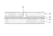
- FIG. 1 is a configuration diagram of a main part schematically showing a jig for joining aluminum materials.
- FIG. 2A is a process explanatory view showing a state in which the first aluminum wrought material is arranged in the internal space of the jig.
- FIG. 2B is a process explanatory view showing a state in which the molten aluminum is injected into the internal space shown in FIG. 2A.
- FIG. 3A is a process explanatory view showing the state in which the molten aluminum is filled in the internal space and solidified in stages.
- FIG. 3B is a process explanatory view showing the state in which the molten aluminum is filled in the internal space and solidified in stages.
- FIG. 1 is a configuration diagram of a main part schematically showing a jig for joining aluminum materials.
- FIG. 2A is a process explanatory view showing a state in which the first aluminum wrought material is arranged in the internal space of the jig.
- FIG. 2B is
- FIG. 3C is a process explanatory view showing the state in which the molten aluminum is filled in the internal space and solidified in stages.
- FIG. 3D is a process explanatory view showing the state in which the molten aluminum is filled in the internal space and solidified in stages.
- FIG. 3E is a process explanatory view showing the state in which the molten aluminum is filled in the internal space and solidified in stages.
- FIG. 4A is a process explanatory view showing a state in which the aluminum wrought material is arranged in the internal space inside the jig.
- FIG. 4B is a process explanatory view showing a state in which the molten aluminum is injected into the internal space shown in FIG. 4A.
- FIG. 5A is a process explanatory view showing a state in which a plurality of through holes and recesses are provided in the internal space inside the jig.
- FIG. 5B is a process explanatory view showing a state in which the molten aluminum is injected into the internal space shown in FIG. 5A.
- FIG. 6A is a process explanatory view showing a state in which a pair of aluminum wrought materials are arranged in the internal space inside the jig.
- FIG. 6B is a process explanatory view showing a state in which the molten aluminum is injected into the internal space shown in FIG. 6A.
- FIG. 7A is a process explanatory view showing a state in which an aluminum wrought material having a pilot hole is arranged in the internal space inside the jig.
- FIG. 7B is a process explanatory view showing a state in which the molten aluminum is injected into the internal space shown in FIG. 7A.
- FIG. 8A is a process explanatory view showing a state in which a pair of tubular aluminum wrought materials are arranged in the internal space inside the jig.
- FIG. 8B is a process explanatory view showing a state in which the molten aluminum is injected into the internal space shown in FIG. 8A.
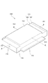
- FIG. 9 is a schematic perspective view showing a main part of a jig for forming a joint body of the seventh joint form.
- FIG. 9 is a schematic perspective view showing a main part of a jig for forming a joint body of the seventh joint form.
- FIG. 10 is a partial cross-sectional perspective view of the jig cut along the line A1-O-A2 of FIG.
- FIG. 11 is a cross section of the jig shown in FIG. 9 along the lines A1-O-A2, and is an explanatory view showing how the filler metal is supplied to the filling space.
- FIG. 12A is an explanatory view showing a state before filling the jig with the filler metal.
- FIG. 12B is an explanatory diagram showing a state when the filler material is filled in the jig.
- FIG. 13 is a perspective view of a joined body in which a metal material and a filler metal material are joined.
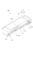
- FIG. 14 is a schematic perspective view showing a main part of a jig for forming a joint body of the eighth joint form.
- FIG. 15 is a partial cross-sectional perspective view of the jig cut along the line XV-XV of FIG.
- FIG. 16 is a partial cross-sectional perspective view of the jig cut along the line XVI-XVI of FIG.
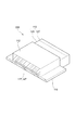
- FIG. 17 is a schematic perspective view showing a main part of a jig for forming a joint body of a ninth joint form.
- FIG. 18 is a partial cross-sectional perspective view of the jig cut along the line XVIII-XVIII of FIG.
- FIG. 19 is a partial cross-sectional perspective view of the jig cut along the XIX-XIX line of FIG.
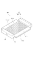
- FIG. 20 is a schematic perspective view showing a jig in a state where the upper metal material of FIG. 17 is removed.
- FIG. 21 is a photomicrograph showing a cross section of a bonded body in which a metal material and a filler material are solid-diffusion bonded.
- FIG. 1 is a configuration diagram of a main part schematically showing a jig 10 for joining aluminum materials.
- the jig 10 includes a first jig 11 and a second jig 13 arranged so as to face each other.
- the first jig 11 and the second jig 13 are movable in a direction in which they are separated from each other and approach each other by a moving mechanism (not shown).
- a plate-shaped first aluminum wrought material 15 is arranged along the first jig 11.
- a gap 19 is provided between the first aluminum wrought material 15 and the second jig 13.
- the second jig 13 has a hot water supply port 21 that communicates with the internal space.
- the first jig 11 has a contact surface 11a that abuts on one surface (outer surface) 15a of the first aluminum wrought material 15 and supports the first aluminum wrought material 15.
- the first aluminum wrought material 15 may be placed on the contact surface 11a of the first jig 11, or may be fixed to the contact surface 11a by using a fixing means (not shown). Good.
- the second jig 13 has a gap 19 between the first aluminum wrought material 15 and the other surface (inner side surface) 15b, and is arranged so as to face the first aluminum wrought material 15.
- the hot water supply port 21 of the second jig 13 is connected to a supply source of the molten aluminum 17 (not shown), and supplies the molten aluminum 17 to the gap 19.
- the hot water supply port 21 is at least an outlet portion 21a connected to the gap 19 and is preferably formed along the vertical direction of the inner side surface 15b of the first aluminum wrought material 15. Further, the axial direction of the hot water supply port 21 may be inclined from the vertical direction of the inner side surface 15b of the first aluminum wrought material 15.
- the opening shape of the hot water supply port 21 can be various shapes such as circular, elliptical, positive, rectangular, and triangular.
- the molten aluminum 17 when the molten aluminum 17 is injected from the hot water supply port 21 into the gap 19 of the internal space, the molten aluminum 17 first collides with the surface (inner side surface 15b) of the first aluminum wrought material 15. Next, the flow direction is changed to flow along the inner side surface 15b of the first aluminum wrought material 15.
- the molten aluminum 17 is filled in the gap 19 between the inner side surface 15b of the first aluminum wrought material and the second jig 13.
- the molten aluminum 17 solidifies, a bonded body in which the first aluminum wrought material 15 and the molten aluminum 17 are integrated is obtained.
- the jig 10 described above has a vertical configuration in which the first jig 11 and the second jig 13 overlap in the vertical direction, but may have a horizontal configuration in which the first jig 11 and the second jig 13 overlap in the horizontal direction.
- the layout of each part of the jig 10 is not shown, the support mechanisms of the first jig 11 and the second jig 13, the fixing member for fixing the first aluminum wrought material 15 in the mold, and the molten aluminum. Can be appropriately selected according to the arrangement form of each part such as the supply part for supplying the hot water supply port 21 and the temperature control part for controlling the mold temperature.
- first aluminum wrought material 15 2000 series, 3000 series, 4000 series, 5000 series, 6000 series, 7000 series aluminum alloys, or 1000 series pure aluminum wrought material can be used. From the viewpoint of weldability, 5000 series, 6000 series, and 7000 series aluminum alloys are particularly preferable.
- the first aluminum wrought material 15 is not limited to a plate material, but may be an extruded shape material (pipe material, hollow, solid, irregular cross-section shape material) or a forged material (plate material, ribbed material). Further, the surface of the first aluminum wrought material 15 may be subjected to various surface treatments such as a blast treatment, an etching treatment, and a brush polishing treatment as preliminary treatments. In that case, the organic matter on the surface of the first aluminum wrought material 15 is removed, and the bonding quality between the first aluminum wrought material 15 and the aluminum casting in which the molten aluminum 17 is solidified is improved.
- Examples of the material of the molten aluminum 17 include AC4C, AC4CH, AC2B (JIS H 5202), ADC 12 (JIS H 5302) and the like.
- the aluminum wrought material such as the first aluminum wrought material 15 and the molten aluminum 17 may be referred to as “aluminum material”.
- the internal space referred to here is formed by a jig 10 (first jig 11, second jig 13) made of a material having a melting point higher than that of the first aluminum wrought material 15 and the molten aluminum 17, and is made of aluminum.
- This is a flow path through which the molten metal 17 flows.
- This flow path may be a space defined by a cavity or groove formed in the jig 10 and the first aluminum wrought material 15.
- the shape of the internal space defined by the first jig 11 and the second jig 13 is arbitrary, and an appropriate shape according to the shape of the first aluminum wrought material 15 to be used, the shape of the joint surface thereof, and the like. Is set to.
- the method of joining the aluminum material described below is a method of joining the aluminum wrought material and the molten aluminum with simple and high strength, and basically the following steps (1) and (2) are performed in this order. It is to be carried out.
- the molten aluminum 17 is pressurized and injected from the hot water supply port 21 toward the first aluminum wrought material 15 and collides with the surface (inner side surface) 15b of the first aluminum wrought material 15 to cause the first aluminum.
- (2) A step of flowing the molten aluminum 17 into the internal space along the surface (inner side surface) 15b of the first aluminum wrought material 15 around the collision position together with the amount removed by digging the first aluminum wrought material 15. ..
- the molten aluminum is pressurized and injected toward the first aluminum wrought material 15 arranged in the internal space inside the jig 10.
- the molten aluminum 17 vigorously collides with the inner side surface 15b of the first aluminum wrought material 15.
- an external force due to the collision of the molten aluminum 17 acts on the first aluminum wrought material 15, and the collision position of the first aluminum wrought material 15 is dug down. That is, the material surface layer at the collision position is gradually removed by the molten aluminum 17, and a thinned portion is formed at the collision position.
- the collision direction of the molten aluminum 17 is preferably the direction perpendicular to the inner side surface 15b of the first aluminum wrought material 15, but it may be appropriately changed depending on the shape of the internal space and the like.
- the collision direction can be adjusted by changing the axial direction of the hot water supply port 21 or by providing a gate having an appropriate shape at the hot water supply port 21.
- the molten aluminum 17 after the collision spreads from the collision position of the first aluminum wrought material 15 along the inner side surface 15b and covers the inner side surface 15b which is a joint surface.
- a high-strength bonded state is obtained in which the inner side surface 15b of the first aluminum wrought material 15 and the aluminum casting in which the molten aluminum 17 is solidified are solid-phase diffusion bonded.
- the time from the start of supply of the molten aluminum 17 to the completion of filling of the internal space depends on the volume of the internal space, but is 1 second or less, preferably 0.8 seconds or less, and more preferably 0.5 seconds or less. .. In such a short time, a bonded body in which the first aluminum wrought material 15 and the aluminum casting 33 are bonded with high strength can be obtained.
- the jig 10 preferably includes an overflow (not shown) for storing the molten aluminum 17 overflowing from the gap 19.
- the overflow can be of a structure used in general injection molding techniques.
- the molten aluminum 17 is filled in the gap 19 from the hot water supply port 21. Then, the molten aluminum 17 overflows from the gap 19, flows to the overflow and is stored in the overflow, and then the supply of the molten aluminum 17 is stopped. According to this, the molten aluminum 17 flows in the gap 19 without stagnation.
- the jig 10 preferably includes a heater that heats and retains at least one of the first jig 11 and the second jig 13.
- the temperature controller (not shown) that controls the heater preheats the heater before the molten aluminum 17 is injected into the gap 19, and heats the first aluminum wrought material 15 and the second jig 13 at 400 ° C. Keep at ⁇ 500 ° C. According to this, even if the gap 19 serving as the flow path of the molten aluminum 17 is, for example, a thin wall of 3 mm or less, the molten aluminum 17 flowing through the gap 19 does not solidify during the flow, and a smooth flow without stagnation. It becomes.
- the first jig 11 and the second jig 13 are separated from each other. Then, the joint body in which the first aluminum wrought material 15 and the aluminum casting are joined is taken out from the jig 10. In this joint, the joint surface of the first aluminum wrought material 15 is solid-phase diffusion bonded to the aluminum casting. In the aluminum casting, unnecessary parts (overflow, etc.) such as a portion formed by the hot water supply port 21 are appropriately cut.
- first to sixth joining forms having different joining forms as examples. explain.
- the joining form is not limited to these forms, and each form can be combined.
- FIG. 2A is a process explanatory view showing a state in which the first aluminum wrought material is arranged in the internal space of the jig.
- FIG. 2B is a process explanatory view showing a state in which the molten aluminum is injected into the internal space shown in FIG. 2A.
- the first jig 11 and the second jig 13 are separated from each other, the flat plate-shaped first aluminum wrought material 15 is inserted between the jigs, and the first aluminum wrought material 15 is inserted. 1 Install along the jig 11. Then, the first jig 11 and the second jig 13 are brought close to a predetermined position and fixed. In this state, the molten aluminum 17 is injected from the hot water supply port 21. Then, as shown in FIG. 2B, the surface layer at the collision position of the molten aluminum 17 of the first aluminum wrought material 15 is gradually removed, and the thinned portion 31 is formed at the collision position. Further, the molten aluminum after the collision flows along the inner side surface 15b exposed in the internal space of the first aluminum wrought material 15.
- the inner side surface 15b which is the joint surface of the first aluminum wrought material 15, is covered with the aluminum casting 33.
- the aluminum casting 33 is integrally formed with a protrusion 35 in which the molten aluminum 17 is solidified at the thinned portion 31.
- the protrusion 35 is formed in a region where the first aluminum wrought material 15 is recessed in the thickness direction, and protrudes along the axial direction of the hot water supply port 21.
- the protrusion 35 of this configuration is formed within the thickness of the first aluminum wrought material 15.
- the protrusion 35 increases the joint area between the first aluminum wrought material 15 and the aluminum casting 33, and projects out of the surface to exert a non-slip effect on the joint surface. For example, when an external force in a direction parallel to the joint surface or a twisting force in the joint surface acts on the joint body of the first aluminum wrought material 15 and the aluminum casting 33, the protrusion 35 expands the first aluminum. It becomes an engaging portion between the drawn material 15 and the aluminum casting 33, and peeling at the joint surface is less likely to occur. By forming the protrusion 35, the joint strength can be greatly improved as compared with the case where the first aluminum wrought material 15 and the aluminum casting 33 are surface-connected between the flat surfaces.
- the joint surface of the first aluminum wrought material 15 and the aluminum casting 33 are solid-phase diffusion bonded to each other, and high bonding strength can be obtained.
- the first aluminum wrought material 15 and the aluminum casting 33 are solid-phase diffusion-bonded as follows.
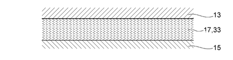
- 3A to 3E are process explanatory views showing the state in which the molten aluminum is filled in the flow path and solidified in stages.
- the first aluminum wrought material 15 is arranged in the gap 19 which is the flow path of the molten aluminum with the inner side surface 15b (joint surface) exposed.
- a surface layer 37 containing an oxide film, an organic substance such as oil, and a foreign substance such as dust is formed on the inner surface 15b of the first aluminum wrought material 15, which is a metal material, and the metal base material is exposed as it is. There is no such thing.
- the molten aluminum is sprayed from the hot water supply port 21 shown in FIG. 2A toward the gap 19 at high pressure. Then, two flows are generated in the hot water supply port 21 and the gap 19 in chronological order. That is, a leading flow containing droplets of the molten aluminum 17 and a trailing flow composed of the molten aluminum flowing in the gap 19 following the leading flow are generated.
- the generated fine particles 43 repeatedly collide with the first aluminum wrought material 15 in the preceding flow, and scrape off the surface layer 37 of the first aluminum wrought material 15 as shown in FIG. 3C. Then, the new surface 45 from which the surface layer 37 has been removed is exposed on the first aluminum wrought material 15.
- the new surface 45 of the first aluminum wrought material 15 is covered with the molten aluminum 17 at a solid phase bonding temperature lower than the melting point of aluminum, and the molten aluminum 17 in the gap 19 is held at a predetermined pressure and time.
- solid phase diffusion occurs between the new surface 45 of the first aluminum wrought material 15 and the aluminum casting 33 in which the molten aluminum 17 is solidified, and both are solid-phase diffusion bonded.
- the joint surface (new surface 45) of the first aluminum wrought material 15 is joined to the aluminum casting 33 in a high-strength solid-phase diffusion bonding state.
- the first aluminum wrought material 15 is arranged in the internal space of the jig 10 with the joint surface exposed, and the molten aluminum 17 is injected into the gap 19 at a high pressure to form the first aluminum wrought material 15.
- a new surface is formed on the joint surface of the aluminum.
- the formed new surface is immediately covered with the molten aluminum 17. Therefore, the first aluminum wrought material 15 and the aluminum casting 33 are easily solid-phase diffusion bonded and bonded with high strength.
- the aluminum droplets here are droplets of molten metal generated when a pressurized aluminum molten metal is sprayed, but the droplets are not limited to this.
- the droplet of aluminum may be a droplet produced by other known means.
- each step of forming droplets, forming a new surface, and covering the new surface with a molten metal can be performed in the atmosphere, but may be performed in a vacuum or in an inert gas atmosphere. In that case, the formation of an oxide film on the new surface can be prevented more reliably.
- the first aluminum wrought material 15, the first jig 11, and the second jig 13 are heated and kept warm by a heater (not shown) when the molten aluminum 17 is injected into the gap 19, for example, the thickness is increased.
- the molten aluminum 17 can be smoothly flowed in the region to be the thin-walled portion.
- the aluminum casting 33 can be brought into a high quality state with almost no filling or blow holes.
- the flow of the molten aluminum 17 in the gap 19 can be smoothed. As a result, the stagnation of the molten aluminum 17 in the flow path is suppressed.
- FIG. 4A is a process explanatory view showing a state in which the aluminum wrought material is arranged in the internal space inside the jig.
- FIG. 4B is a process explanatory view showing a state in which the molten aluminum is injected into the internal space shown in FIG. 4A.
- the same members and parts as those described above will be given the same reference numerals to simplify or omit the description.
- the first jig 11A of the present joint form is provided with a recess 51 at a position facing the hot water supply port 21 on the contact surface 11a with the first aluminum wrought material 15.
- the recess 51 preferably has an opening area larger than the opening area of the hot water supply port 21 around the axis L of the hot water supply port 21.
- the inner diameter of the recess 51 is preferably larger than the inner diameter of the hot water supply port 21.
- the first aluminum stretch is formed between the hot water supply port 21 and the runner 15c of the first aluminum wrought material 15 and in the recess 51.
- a locking portion 53 is formed that sandwiches the outer surface 15a and the inner surface 15b of the material 15 in the thickness direction.
- the locking portion 53 has a shaft portion 55 formed between the hot water supply port 21 and the runner 15c, and a head portion 56 formed by the recess 51 and connected to the shaft portion 55.
- the first aluminum wrought material 15 is placed between the head 56 protruding outward from the runner 15c and the aluminum casting 33 formed in the gap 19 (see FIG. 4A). Insert it. That is, the first aluminum wrought material 15 and the aluminum casting 33 are joined so as to be riveted. As a result, the joint strength between the first aluminum wrought material 15 and the aluminum casting 33 is improved.
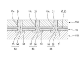
- FIG. 5A is a process explanatory view showing a state in which a plurality of through holes and recesses are provided in the internal space inside the jig.
- FIG. 5B is a process explanatory view showing a state in which the molten aluminum is injected into the internal space shown in FIG. 5A.
- the first jig 11B and the second jig 13A of this joint form are configured so that the locking portions 53 shown in FIG. 4B described above are formed at a plurality of locations.
- the second jig 13A is provided with a plurality of (three as an example) hot water supply ports 21.
- the first jig 11B is provided with the above-mentioned recesses 51 at positions facing the hot water supply ports 21.
- the joint strength between the first aluminum wrought material 15 and the aluminum casting 33 can be further improved.
- the locking portions 53 can be arranged at equal intervals to obtain uniform bonding strength, or the arrangement intervals can be widened or narrowed depending on the location to obtain a desired bonding strength distribution. For example, when a location where a higher bonding strength is required compared to the surroundings is known in advance, the mechanical strength of the bonded body can be efficiently increased by increasing the arrangement density of the locking portion 53 at that location from the surroundings. Can be improved.
- FIG. 6A is a process explanatory view showing a state in which a pair of aluminum wrought materials are arranged in the internal space inside the jig.
- FIG. 6B is a process explanatory view showing a state in which the molten aluminum is injected into the internal space shown in FIG. 6A.
- the internal space between the first jig 11 and the second jig 13 faces the first aluminum wrought material 15 arranged on the first jig 11 side.
- the second aluminum wrought material 63 is arranged.
- the second aluminum wrought material 63 has a gap 19 with the inner side surface 15b of the first aluminum wrought material 15 and is arranged along the contact surface 13a of the second jig 13.
- the second aluminum wrought material 63 is fixed to the second jig 13 by an appropriate fixing means (not shown).
- Other configurations are the same as those shown in FIG. 2A described above.
- the outlet side of the hot water supply port 21 formed in the second jig 13 is closed by the second aluminum wrought material 63.
- the molten aluminum 17 When the molten aluminum 17 is pressurized and injected from the hot water supply port 21 with the above configuration, the molten aluminum 17 collides with the second aluminum wrought material 63 facing the hot water supply port 21 and the second aluminum wrought material at this collision position. 63 is opened by pressure. As a result, as shown in FIG. 6B, the second aluminum wrought material 63 is formed with a through hole 63c having a shape corresponding to the hot water supply port 21.
- the molten aluminum 17 is injected into the gap 19 from the hot water supply port 21 through the through hole 63c.
- the molten aluminum 17 injected at this time collides with the first aluminum wrought material 15 through the hot water supply port 21 and the through hole 63c. Then, as in the case shown in FIG. 2B, the wall thinning portion 31 is formed at this collision position. The thinned portion 31 grows in the thickness direction of the first aluminum wrought material 15 and forms a protruding portion 35 made of the aluminum casting 33 after the molten aluminum 17 is solidified.
- the first aluminum wrought material 15 and the second aluminum wrought material 63 which overlap in the thickness direction, are integrated by joining the inner side surfaces 15b and 63b to each other by the aluminum casting 33.
- a protrusion 35 protruding in the thickness direction of the first aluminum wrought material 15 is formed on the aluminum casting 33.
- a through hole 63c is formed in the second aluminum wrought material 63, and the inner peripheral surface of the through hole 63c is joined to the aluminum casting 33.
- the through hole 63c is formed in the second aluminum wrought material 63 when the molten aluminum 17 is injected, the number of man-hours can be reduced and the workability can be improved as compared with the case where the prepared hole is machined in advance.
- FIG. 7A is a process explanatory view showing a state in which an aluminum wrought material having a pilot hole is arranged in the internal space inside the jig.
- FIG. 7B is a process explanatory view showing a state in which the molten aluminum is injected into the internal space shown in FIG. 7A.
- a pilot hole 63d is provided in advance at a position facing the hot water supply port 21 in the second aluminum wrought material 63 shown in FIG. 6A described above.
- the prepared hole 63d may be a through hole machined by a drill or the like, or may be a notch from which a part of the plate material is removed. That is, the prepared hole 63d referred to here may have any form as long as the hot water supply port 21 communicates with the gap 19.
- the molten aluminum 17 is filled in the gap 19 through the prepared hole 63d of the second aluminum wrought material 63A, as shown in FIG. 7B. Further, the injected molten aluminum 17 collides with the inner side surface 15b of the first aluminum wrought material 15 to form a wall thinning portion 31 on the first aluminum wrought material 15. The thinned portion 31 grows in the thickness direction of the first aluminum wrought material 15. Then, as in the case shown in FIG. 2B, after the molten aluminum 17 is solidified, the protrusion 35 of the aluminum casting 33 is formed.
- the pilot hole 63d is provided in the second aluminum wrought material 63 before the injection of the molten aluminum 17, the molten aluminum 17 to be injected into the hot water supply port 21 can be directly injected into the gap 19. As a result, the filling of the molten aluminum 17 into the gap 19 can be completed quickly, and the tact time can be shortened.
- the prepared hole 63d is shown to have a size substantially equal to that of the hot water supply port 21, but for example, the opening area may be larger than that of the hot water supply port 21. In that case, the positioning accuracy of the second aluminum wrought material 63A with respect to the second jig 13 can be reduced, and the workability can be improved. Further, when the prepared hole 63d is made into a hole having an opening area smaller than that of the hot water supply port 21, the flow velocity of the molten aluminum 17 supplied into the gap 19 becomes high. As a result, the collision speed with the first aluminum wrought material 15 is increased, and the formation of the thinned portion 31 can be promoted.
- the flow velocity of the molten aluminum 17 flowing along the inner surface 15b of the first aluminum wrought material 15 and the inner side surface 63b of the second aluminum wrought material 63A is increased, and the formation of the above-mentioned new surface can be further promoted.
- FIG. 8A is a process explanatory view showing a state in which a pair of tubular aluminum wrought materials are arranged in the internal space inside the jig.
- FIG. 8B is a process explanatory view showing a state in which the molten aluminum is injected into the internal space shown in FIG. 8A.
- the pair of aluminum wrought materials used here are the first aluminum wrought material 65 and the second aluminum wrought material 67, which have different diameters (cylindrical shapes).
- the first aluminum wrought material 65 and the second aluminum wrought material 67 are supported by a substantially cylindrical core 71 that functions as the first jig described above.
- the core 71 has a small diameter portion 71a along the axial direction and a large diameter portion 71b having a diameter larger than that of the small diameter portion 71a.
- the first aluminum wrought material 65 is supported by abutting the inner peripheral surface 65a on the outer peripheral surface 73 of the small diameter portion 71a.
- the second aluminum wrought material 67 is supported by abutting the inner peripheral surface 67a on the outer peripheral surface 75 of the large diameter portion 71b. Whether the outer diameter of the small diameter portion 71a of the core 71 is equal to or slightly smaller than the inner diameter of the first aluminum wrought material 65 and the outer diameter of the large diameter portion 71b is equal to the inner diameter of the second aluminum wrought material 67. Slightly small.
- first aluminum wrought material 65 and the second aluminum wrought material 67 supported by the core 71 have an overlapping portion 77 in which the pipe end portions overlap each other in the radial direction with respect to the axial direction.
- a radial gap 19 is formed between the outer peripheral surface 65b of the first aluminum wrought material 65 and the inner peripheral surface 67a of the second aluminum wrought material 67.
- a tubular shape that covers the first aluminum wrought material 65 and the second aluminum wrought material 67 supported by the core 71 as described above, and the end face 71c of the core 71, and functions as the second jig described above.
- a split jig 79 is arranged.
- the tubular split mold 79 has one split mold 79A arranged on the upper side of FIG. 8A and the other split mold 79B arranged on the lower side.
- One split type 79A and the other split type 79B are each provided with a hot water supply port 21.
- the hot water supply port 21 may be provided at one location on each of the split molds 79A and 79B, or may be provided at a plurality of locations. Further, the hot water supply port 21 may be provided only in one of the split mold 79A and the other split mold 79B.
- the inner peripheral side of the hot water supply port 21 is closed by the second aluminum wrought material 67.
- the portion of the second aluminum wrought material 67 facing the hot water supply port 21 opens to form a through hole 67b, as shown in FIG. 8B.
- the molten aluminum 17 collides with the first aluminum wrought material 65 through the formed through hole 67b.
- the thinned portion 31 is formed in the first aluminum wrought material 65, and the molten aluminum 17 is filled in the gap 19.
- the protrusion 35 of the aluminum casting 33 is formed at the position of the thinned portion 31 of the first aluminum wrought material 65.
- the overlapping portions 77 can be joined to each other with high strength by the aluminum casting 33. Further, by forming the protrusion 35 and the through hole 67b, the joint strength between the first aluminum wrought material 65 and the second aluminum wrought material 67 of the aluminum casting 33 can be further improved.
- the prepared hole described above may be formed in advance at a portion of the second aluminum wrought material 67 facing the hot water supply port 21.
- the molten aluminum 17 can be directly injected into the gap 19
- the filling of the molten aluminum 17 in the gap 19 can be completed quickly, and the tact time can be shortened.
- the first aluminum wrought materials 15 and 65 described above are hereinafter referred to as "metal materials” as an expression that expands the degree of freedom in material selection, and the molten aluminum 17 is also simply referred to as "molten metal”. Further, the solidified molten metal is called a "additive material”. Further, as the metal material and the molten metal (filling material), for example, a zinc alloy, a magnesium alloy, or a copper alloy can be used depending on the conditions.
- the metal material can be not only a material such as a plate or an extruded material, but also a processed member such as a press-molded product or a bent-molded product having a surface joint portion.
- the aluminum casting may be a member having ribs, flanges or the like other than the joint surface.
- the solid-phase diffusion bonding method for a metal material is a method for easily solid-phase diffusion bonding between a metal material and a filler material, and basically includes the following steps (1) to (5). .. (1) A step of exposing and arranging the surface to be joined of a metal material in the flow path. (2) A step of generating droplets of filler metal in the flow path. (3) A step of colliding the solidified fine particles with the surface to be bonded to form a new surface on the surface to be bonded. (4) A step of covering the new surface with a molten metal of a filler material after the formation of the new surface and before the oxide film is formed. (5) A step of pressurizing the molten metal in the flow path while maintaining the solid phase diffusion bonding temperature to form a solid phase diffusion bonding between the new surface and the filler metal.
- the flow path referred to here is a flow path formed in a jig made of a material having a melting point higher than that of a metal material and a filler material, and includes a cavity formed in the jig and a groove formed in the jig. It is a space defined by metal materials.
- the shape of the jig is arbitrary, and an appropriate shape is used depending on the shape of the metal material and the surface to be joined. The molten metal of the filler metal is supplied into the flow path of the jig.
- the molten metal When supplying the molten metal of the filler material into the flow path of the jig, the molten metal is injected into the flow path and supplied. Then, droplets of molten metal are generated in the flow path. The generated droplets flow in the flow path prior to the molten metal. The droplets proceed while being deheated in the flow path and solidify in the flow path to become a large number of fine particles. The fine particles collide with the bonded surface of the metal material exposed in the flow path and scrape off the surface layer of the bonded surface. A new surface is formed on the surface to be joined, with the surface layer scraped off.
- the molten metal of the filler material that flows after the droplets covers the new surface of the metal material in the flow path. Then, the molten metal in the flow path is pressurized while being maintained at the solid phase diffusion bonding temperature. As a result, solid-phase diffusion bonding is performed between the new surface and the filler metal.
- the surface of the metal material is not melted, and the molten metal of the filler material is simply sprayed into the flow path without pre-treating the surface of the metal material.
- Solid phase diffusion bonding can be performed. Further, even if the surface to be joined of the metal material has a complicated shape, it is only necessary to form a new surface following the shape and cover it with the molten metal, and the joining process is not complicated. Therefore, the degree of freedom in selecting the joining member can be increased. Furthermore, by pressurizing the molten metal of the filler material in the filling space while maintaining it at the solid phase bonding temperature, solid phase diffusion proceeds at the interface between the new surface of the metal material and the filler material, and both materials have high strength. Is joined to. After that, by separating the jig from the metal material, a bonded body in which the metal material and the filler metal are integrated by solid phase diffusion bonding can be obtained.
- the filler metal is one member constituting the bonded body. Since the filler metal does not melt the metal material, it is composed of a material having a melting point lower than that of the metal material, and a material in which atoms are diffused with the metal material to be joined is selected. Further, the filler metal may be a material made of the same type of metal as the metal material.
- the droplets of the molten metal of the filler material are droplets obtained by applying pressure to the molten metal to inject and scatter the molten metal. The steps of forming droplets, forming a new surface, and covering the new surface with a molten metal can be performed in the atmosphere, but may be performed in a vacuum or in an inert gas atmosphere.
- the formed new surface is covered with the molten metal as it is, so that a new oxide film is not formed on the new surface. Therefore, the molten metal comes into contact with the surface of the new surface without (almost no) oxide film, and the atom transfer between the metal material and the filler material at the bonding interface is less likely to be hindered.
- the bonding area can be expanded and the bonding strength can be increased.
- the jig for forming the joint shown below is an example, and is not limited thereto.
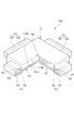
- FIG. 9 is a schematic perspective view showing a main part of a jig for forming a joint body of the seventh joint form.
- FIG. 10 is a partial cross-sectional perspective view of the jig cut along the line A1-O-A2 of FIG.
- the jig 100 includes a flow path forming block 111 and a flow path end block 113 connected to a part of the flow path forming block 111.
- the flow path forming block 111 is arranged so as to face the metal material 115 which is a component of the joint in the vertical direction.
- the metal material 115 shown here has a quadrangular flat plate shape.
- the flow path forming block 111 is relatively approachable and detachable from the upper surface 115a of the metal material 115 by a moving mechanism (not shown).
- the lower surface 111a facing the metal material 115 is arranged so as to be separated from the upper surface 115a of the metal material 115.
- a filling space 117 is defined between the upper surface 115a of the metal material 115 and the lower surface 111a of the flow path forming block 111.
- an inflow port 119 is formed which penetrates from the upper surface 111b to the lower surface 111a of the flow path forming block 111 and communicates with the filling space 117.
- the inflow port 119 is a flow path for supplying the molten metal of the filler material to the filling space 117, and is not limited to one location, and may be provided at a plurality of locations.
- the flow path end blocks 113 of this configuration are provided on each of the four sides that are the outer edges of the quadrangular flow path forming block 111.
- the flow path end block 113 has a connection flow path 121 whose one end is connected to the filling space 117 of the flow path forming block 111, and a storage portion 123 which is connected to the other end of the connection flow path 121.
- the connecting flow path 121 and the storage unit 123 accommodate the molten metal overflowing from the filling space 117.
- connection flow path 121 and the storage portion 123 are closed with the groove forming member 125 in which the concave groove serving as the connection flow path 121 and the storage portion 123 is formed, and the concave groove serving as the storage portion 123 of the groove forming member 125.
- An example of forming the pressing member 127 in close contact with the pressing member 127 is shown, but the present invention is not limited to this configuration.
- the jig 100 described above has the metal material 115 and the flow path forming block 111 stacked in the vertical direction, but the present invention is not limited to this, and a configuration in which the metal material 115 and the flow path forming block 111 are stacked in the horizontal direction may be used, and the layout thereof is the jig support mechanism. , It can be appropriately selected according to the arrangement form of each part such as the filler metal supply part and the temperature control part.
- FIG. 11 is a cross section of the jig 100 shown in FIG. 9 along the lines A1-O-A2, and is an explanatory view showing how the filler metal 131 is supplied to the filling space 117.
- the flow path end block 113 is brought into close contact with the outer edge of the flow path forming block 111 to communicate the inflow port 119, the filling space 117, the connection flow path 121, and the storage portion 123.
- a flow path of the filler metal 131 is formed.
- a jig support mechanism that supports the jig 100 in the state shown in FIG. 11 and pressurizes the flow path forming block 111 toward the metal material 115.
- a filler material supply unit that supplies the filler material to the jig 100 and a temperature control unit that holds the filling space 117 at a predetermined temperature are used.
- FIGS. 12A and 12B An example of the jig support mechanism, the filler material supply unit, and the temperature control unit described above is schematically shown in FIGS. 12A and 12B.
- FIG. 12A is an explanatory diagram showing a state before filling the jig 100 with the filler material
- FIG. 12B is an explanatory diagram showing a state when the jig 100 is filled with the filler material.
- the jig support mechanism 133 has a lower mold 135 and an upper mold 137, and arranges the jig 100 between the lower mold 135 and the upper mold 137. That is, the jig support mechanism 133 brings each flow path end block 113 and the metal material 115 into close contact with the flow path forming block 111.
- a storage recess 135a for accommodating the jig 100 and the metal material 115 is formed in the lower mold 135, and a heater 139 is embedded at a position in the storage recess 135a for accommodating the metal material 115.
- the heater 139 is connected to a temperature controller 141 that controls the heating temperature.
- the heater 139 and the temperature controller 141 function as a temperature control unit 143 that controls the temperature of the metal material 115 by heating the heater 139.
- the upper mold 137 is connected to a drive mechanism (not shown) capable of pressing the flow path forming block 111 and the flow path end block 113 toward the lower mold 135 (pressure P1). Further, the upper die 137 is provided with a filler material supply flow path 137a for supplying the filler material to the inflow port 119 of the flow path forming block 111 in communication with the inflow port 119 of the flow path forming block 111.
- the filler metal (molten metal) in a molten state is supplied from the filler metal supply unit 145 to the filler metal supply flow path 137a.
- the filler metal 147 pumped from the filler metal supply unit 145 is supplied from the nozzle unit 146 provided with an orifice or the like. It is injected into the flow path 137a.
- the above-mentioned droplets move in advance in the flow path and reach the filling space 117 through the inflow port 119 of the flow path forming block 111.
- the molten metal 147 moves through the flow path and reaches the filling space 117 through the inflow port 119.
- the nozzle portion 146 may be provided at the inflow port 119 of the flow path forming block 111 instead of the upper die 137. In that case, the molten metal 147 is directly injected into the inflow port 119, and the droplets and the molten metal 147 are vigorously supplied to the filling space 117.
- the droplets and the molten metal 147 which are fluids flowing from the inflow port 119 into the filling space 117, flow through the filling space 117 in this order, and the head of the flow is discharged to the storage unit 123 through the connecting flow path 121.
- the temperature controller 141 preheats the heater 139.
- the heater 139 is heated and the metal material 115 is held in a state of being heated to 400 ° C. to 500 ° C.
- the heating set temperature may be a temperature lower than the melting point of the metal material 115 and the filler metal 131, and may be an appropriate temperature for solid-phase diffusion bonding of both.
- the metal material 115 and the fillering material 131 are 1000 series (melting point about 640 ° C.), 3000 series (melting point about 630 ° C.), 5000 series (melting point about 600 ° C.), and 6000 series (melting point about 580 ° C.).
- the upper limit of the heating set temperature may be set to 530 ° C. and 550 ° C.
- the molten metal 147 (and droplets) at the initial stage of flow supplied to the filling space 117 may contain foreign substances and impurities such as air, oxides, and organic substances. Since the molten metal 147 (and droplets) continuously flows from the space outer edge portion 117a of the filling space 117 to the storage portion 123, such foreign substances and impurities do not remain in the filling space 117 and enter the storage portion 123. It is discharged. Further, since the molten metal 147 of the filler metal 131 continues to flow toward the storage portion 123, the flow of the molten metal 147 in the filling space 117 does not stay. Therefore, the quality of the filler metal 131 formed by solidifying the molten metal 147 is improved and the porosity is reduced.
- a reaction force F from the flow path forming block 111 toward the upper mold 137 is generated by the pressure of the molten metal 147.
- the pressure received by the jig 100 from the upper mold 137 becomes a pressure P2 larger than the pressure P1 before filling the filler metal.
- This pressure P2 is set in the range of, for example, 260 to 280 MPa in the case of a metal material of an aluminum alloy and a filler material of an aluminum alloy.
- the molten metal 147 of the filler metal 131 is filled in the filling space 117, and the molten metal 147 is held in a pressurized state at a predetermined pressure for at least 10 seconds, preferably 20 seconds or more, and the temperature of the metal material 115 is adjusted. Keep at a predetermined temperature below the melting point. As a result, a bonded body in which the filler metal 131 is solid-phase diffusion bonded to the upper surface 115a of the metal material 115 can be obtained.
- FIG. 13 is a perspective view of a bonded body 151 in which the metal material 115 and the filler metal 131 are joined.
- the inflow port 119, the connection flow path 121, and the storage portion 123, which are cut because they are no longer needed as a product, are shown by dotted lines.
- the filler metal 131 is solid-phase diffusion bonded to the upper surface 115a of the metal material 115 over a wide range.
- the molten metal 147 overflowing from the filling space 117 flows into the storage unit 123, fills the molten metal 147 in the filling space 117, and then ends the supply of the molten metal from the filler material supply unit 145 shown in FIG. 12B. Further, the heating and heat retention of the heater 139 by the temperature control unit 143 is stopped. Then, when the molten metal 147 in the filling space 117 is cooled and solidified, the lower mold 135 and the upper mold 137 are separated from each other, and the bonded body 151 in which the metal material 115 and the filler 131 are solid-phase diffusion bonded is taken out. .. By removing the connection flow path 121 and the storage portion 123 from the joint body 151, the joint body 151 having the appearance shape shown in FIG. 13 can be obtained.
- the metal material 115 is arranged in the filling space 117 with the surface to be bonded exposed, and the molten metal 147 of the filler metal 131 is sprayed into the filling space 117 to spray the metal material 115 on the surface to be bonded.
- the metal material 115 and the filler 131 can be solid-phase diffusion-bonded by forming a new surface on the surface, covering the formed new surface with the molten metal 147 of the filler 131, and pressurizing the filler material 131 for a predetermined time.
- the lower mold 135 is heated and kept warm by the heater 139 shown in FIG. 12B to form, for example, a thin portion having a thickness of 3 mm or less from the filler metal 131. Even in this case, the molten metal 147 can be smoothly flowed in this thin portion. That is, the molten metal 147 does not solidify in the narrow portion of the filling space 117 and the flow of the molten metal 147 does not stop, and the flow of the molten metal 147 does not stagnate due to the increase in viscosity of the molten metal 147 due to the temperature drop.
- the filler metal portion forming a part of the joint can be formed without causing a thinning, and the filler metal 131 can be a high-quality filler metal portion having almost no blow holes or the like. it can. Further, even if the bonded body 151 has a complicated shape, the filler metal portion can be formed by a good flow of the molten metal 147, so that the manufacturing process is not complicated. Therefore, a solid-phase diffusion-bonded bonded body having high bonding strength and rigidity can be manufactured at low cost.
- the flow of the molten metal 147 in the filling space 117 becomes smooth.
- the occurrence of stagnation of the molten metal 147 is suppressed, and the filler metal 131 after solidification becomes homogeneous.
- the hot water flow can be improved over a wide range of the filling space 117, and the filler metal portion after solidification can be made of high quality over a wide range. can do.
- the lower surface 111a of the flow path forming block 111 shown in FIG. 11 may be subjected to a wrinkle processing to physically form a wrinkle pattern (wrinkle).
- the fluidity of the molten metal can be improved by embossing the lower surface 111a of the flow path forming block 111 that defines the filling space 117.
- FIG. 14 is a schematic perspective view showing a main part of the jig 200 for forming the joint body of the eighth joint form.
- FIG. 15 is a partial cross-sectional perspective view of the jig 200 cut along the line XV-XV of FIG.
- FIG. 16 is a partial cross-sectional perspective view of the jig 200 cut along the line XVI-XVI of FIG.
- the jig 200 includes a flow path forming block 112 and flow path end blocks 113 and 114 connected to both ends in the uniaxial direction of the flow path forming block 112.
- the flow path forming block 112 is arranged so as to face the metal material 115, and defines a filling space 117 between the upper surface 115a of the metal material 115 and the lower surface 111a of the flow path forming block 112.
- the filling space 117 of this configuration is formed flat between one flow path end block 114 and the other flow path end block 113, and a wide joint area with the metal material 115 is secured.
- the flow path end block 114 having the inflow port 119 is formed with a flow path communicating with the filling space 117 of the flow path forming block 112, and the flow path end block 113 has the connection flow path 121 and the storage portion 123 described above. Is formed.
- the molten metal of the filler metal is supplied along the plate surface of the metal material 115 as in the first configuration example, so that the object is exposed to the filling space 117 of the metal material 115. A new surface is formed on the joint surface. Immediately after that, the molten metal of the filler metal flows into the new surface and covers the new surface. As a result, a bonded body in which the metal material 115 and the filler metal are solid-phase diffusion bonded is obtained.
- the filling space 117 of the present configuration is a flat space, but the space is not limited to this, and can be any shape such as a space having a bent portion or a curved portion, a space branched into a plurality of lines, and the like.
- FIG. 17 is a schematic perspective view showing a main part of the jig 300 for forming the joint body of the ninth joint form.
- FIG. 18 is a partial cross-sectional perspective view of the jig 300 cut along the line XVIII-XVIII of FIG.
- FIG. 19 is a partial cross-sectional perspective view of the jig 300 cut along the XIX-XIX line of FIG.
- FIG. 20 is a schematic perspective view showing a jig 300 in a state where the upper metal material 115B of FIG. 17 is removed.
- the jig 300 includes flow path forming blocks 111A and 111B and flow path end blocks 113 and 114 connected to both ends of the flow path forming blocks 111A and 111B in the uniaxial direction.
- the jig 300 defines a filling space 117 between a pair of upper and lower plate-shaped metal materials 115A and 115B.
- the pair of metal materials 115A and 115B are stacked in the plate thickness direction at predetermined intervals, and a pair of plate-shaped flow path forming blocks 111A and 111B are arranged between the metal material 115A and the metal material 115B.
- the flow path forming blocks 111A and 111B are arranged so that their side surfaces face each other in the horizontal direction.
- the flat space surrounded by the upper surface of the metal material 115A, the lower surface of the metal material 115B, and the side surfaces of the flow path forming blocks 111A and 111B is the filling space 117.
- a bonded body in which a pair of metal materials 115A and 115B are solid-phase diffusion bonded via a filler metal can be obtained. Also in the case of this configuration, the shape of the filling space 117 is arbitrary.
- FIG. 21 is a photomicrograph showing a cross section of a bonded body in which a metal material (6000 series aluminum alloy plate) and a filler metal material (ADC12) are solid-diffusion bonded. As shown in FIG. 21, at the interface between the metal material arranged on the upper side and the filler material arranged on the lower side, the metal material and the filler metal are solid-phase diffusion bonded.
- a metal material 6000 series aluminum alloy plate
- ADC12 filler metal material
- the present invention is not limited to the above-described embodiment, and can be modified or applied by those skilled in the art based on the combination of the configurations of the embodiments with each other, the description of the specification, and the well-known technique. This is also the subject of the present invention and is included in the scope for which protection is sought.
- the step of supplying the molten metal into the filling space under atmospheric pressure is illustrated, but the step of supplying the molten metal in a vacuum or depressurized state in the filling space may be used before the molten metal is supplied.
- the step may be a step of filling the filling space with an inert gas and then supplying the molten metal. In that case, the formation of an oxide film on the new surface of the metal material can be prevented more reliably.
- the first aluminum wrought material is placed in the internal space defined between the first jig and the second jig having a hot water supply port arranged opposite to the first jig.
- the process of arranging along the first jig and The molten aluminum is pressurized and injected from the hot water supply port toward the first aluminum wrought material, collides with the surface of the first aluminum wrought material, and is combined with the molten aluminum of the first aluminum wrought material.
- the process of digging into the collision position The step of flowing the molten aluminum into the internal space along the surface of the first aluminum wrought material around the collision position, together with the amount removed by digging the first aluminum wrought material, in this order.
- the first jig has a recess formed in the second jig at a position facing the hot water supply port and having an opening area wider than the opening area of the hot water supply port.
- a locking portion for sandwiching the aluminum wrought material in the thickness direction is formed in the recess filled with the molten aluminum after the molten aluminum is solidified.
- the hot water supply port is provided at a plurality of locations of the second jig.
- the recess is provided at each position of the first jig facing the hot water supply port.
- the second aluminum wrought material having a notch or a through hole is exposed at a position where the hot water supply port is exposed to the internal space by the notch or the through hole.
- the method for joining an aluminum material according to any one of (1) to (5), further comprising a step of providing the first aluminum wrought material away from the first aluminum wrought material along the second jig.
- this method of joining aluminum materials an aluminum casting is formed between the inner surfaces of the first aluminum wrought material and the second aluminum wrought material, and the first aluminum wrought material and the second aluminum wrought material are formed. The joint strength of aluminum is improved.
- the first aluminum wrought material is placed in the internal space defined between the first jig and the second jig having a hot water supply port arranged so as to face the first jig.
- the molten aluminum is pressurized and injected into the internal space through the through hole to collide with the surface of the first aluminum wrought material, and the collision position of the first aluminum wrought material with the molten aluminum is determined.
- the process of digging down and The molten aluminum flows into the internal space along the surfaces of the first aluminum wrought material and the second aluminum wrought material around the collision position together with the amount removed by digging the first aluminum wrought material.
- a method of joining aluminum materials in which the steps are performed in this order. According to this method of joining the aluminum material, the molten aluminum is injected into the gap between the first aluminum wrought material and the second aluminum wrought material through the through hole formed in the second aluminum wrought material. It can be instantly joined to the drawn material with high strength.
- the first jig has a recess formed in the second jig at a position facing the hot water supply port and having an opening area wider than the opening area of the hot water supply port.
- a locking portion for sandwiching the aluminum wrought material in the thickness direction is formed in the recess filled with the molten aluminum after the molten aluminum is solidified.
- the hot water supply port is provided at a plurality of locations of the second jig.
- the recess is provided at each position of the first jig facing the hot water supply port.
- the joining strength between the first aluminum wrought material and the aluminum casting is further increased by forming a plurality of places where the aluminum casting penetrates the first aluminum wrought material and reaches the recesses.
- the joint strength can be further improved by locally increasing the arrangement density between the hot water supply port and the recess. According to this, the joint strength of the portion where the strength is particularly required can be easily increased as compared with the surroundings.
- a method for joining an aluminum material which joins a metal material made of wrought aluminum and a filler metal made of cast aluminum.
- the new surface is covered with the molten metal of the filler material, so that the metal material in which the molten metal is solidified and the filler metal are solid-phase diffusion bonded.
- the joint strength of the joint portion can be improved without lowering the workability, and a high-strength joint body in which the aluminum wrought material and the aluminum alloy casting are solid-phase diffusion-bonded can be obtained.
- a pool portion for accommodating the fluid overflowing from the flow path is connected to the flow path on the downstream side in the flow direction of the fluid containing at least the fine particles and the molten metal.
Landscapes
- Engineering & Computer Science (AREA)
- Mechanical Engineering (AREA)
- Pressure Welding/Diffusion-Bonding (AREA)
Abstract
第1治具と、第1治具に対向して配置されて給湯口を有する第2治具と、の間に画成される内部空間に、第1アルミニウム展伸材を第1治具に沿わせて配置する。アルミニウム溶湯を、給湯口から第1アルミニウム展伸材に向けて加圧して注入して、第1アルミニウム展伸材の表面に衝突させて、第1アルミニウム展伸材のアルミニウム溶湯との衝突位置を掘り下げる。アルミニウム溶湯を、第1アルミニウム展伸材の掘り下げによる除去分と共に、衝突位置の周囲の第1アルミニウム展伸材の表面に沿って内部空間に流動させる。
Description
本発明は、アルミニウム材の接合方法に関する。
複数の金属材を面接合する技術として、クラッド圧延がある。クラッド圧延は、複数の金属材を圧延ロールに圧下して、金属材同士を熱間又は冷間で圧着させる技術である。クラッド圧延では、圧着面の変形により酸化被膜が破壊されるため、アルミニウム合金等の、表面に酸化被膜が形成されやすい材料であっても良好な圧着面を得ることができる。
このようなクラッド圧延で金属材を圧着する場合、酸化被膜を確実に破壊するために圧下率を高くする必要があり、複数回の圧延が必要となることもある。このため、複数の金属材の間に中間層を配置し、中間層の一部を液相化して圧延することにより圧下率を低減させる技術が提案されている(特許文献1)。
このようなクラッド圧延で金属材を圧着する場合、酸化被膜を確実に破壊するために圧下率を高くする必要があり、複数回の圧延が必要となることもある。このため、複数の金属材の間に中間層を配置し、中間層の一部を液相化して圧延することにより圧下率を低減させる技術が提案されている(特許文献1)。
これらの技術は、平坦な板の接合しか行うことができず、接合体も必然的に板状となるため、自動車部品のプレス成型品などの三次元形状を有する部材の接合には採用できない。
ところで、さまざまな形状を有する部材を、形状の制約を受けずに面接合する技術として、ろう付け接合や固相拡散接合が考えられる。ろう付けは、接合面全体に満遍なくろう材を広げる必要があるため、施工が難しく、更に専用のろう材や熱処理炉の準備が必要となる。また、固相拡散接合技術は、アルミニウム合金のような酸化被膜が形成されやすい金属材料には、拡散による原子の移動を酸化被膜がブロックするため適用できなかった。
ところで、さまざまな形状を有する部材を、形状の制約を受けずに面接合する技術として、ろう付け接合や固相拡散接合が考えられる。ろう付けは、接合面全体に満遍なくろう材を広げる必要があるため、施工が難しく、更に専用のろう材や熱処理炉の準備が必要となる。また、固相拡散接合技術は、アルミニウム合金のような酸化被膜が形成されやすい金属材料には、拡散による原子の移動を酸化被膜がブロックするため適用できなかった。
そして、近年、鋼材に代わる軽量な構造材としてアルミニウム材の適用が積極的に進められている。このアルミニウム材に対しては、上記した面接合する技術の場合よりも更に高い接合強度を実現させる要望が高い。例えば、接合面に突起部を設けることで、接合面での滑りが抑止されて接合強度を向上させることができるが、加工が煩雑となり、施工性やコストの面で課題が多い。
そこで本発明は、酸化被膜を生じやすいアルミニウム材を、複雑な三次元形状にして接合する場合であっても、加工を煩雑にすることなく接合強度を向上できるアルミニウム材の接合方法を提供することを第1の目的とする。また、接合する金属材形状に自由度があり、強固な酸化被膜を有する場合でも良好な接合を行うことができるアルミニウム材の接合方法を提供することを第2の目的とする。
本発明は下記の構成からなる。
(1) 第1治具と、前記第1治具に対向して配置されて給湯口を有する第2治具と、の間に画成される内部空間に、第1アルミニウム展伸材を前記第1治具に沿わせて配置する工程と、
アルミニウム溶湯を、前記給湯口から前記第1アルミニウム展伸材に向けて加圧して注入し、前記第1アルミニウム展伸材の表面に衝突させて、前記第1アルミニウム展伸材の前記アルミニウム溶湯との衝突位置を掘り下げる工程と、
前記アルミニウム溶湯を、前記第1アルミニウム展伸材の掘り下げによる除去分と共に、前記衝突位置の周囲の前記第1アルミニウム展伸材の表面に沿って前記内部空間に流動させる工程と、をこの順で実施するアルミニウム材の接合方法。
(2) 第1治具と、前記第1治具に対向して配置されて給湯口を有する第2治具と、の間に画成される内部空間に、第1アルミニウム展伸材を前記第1治具に沿わせて配置し、第2アルミニウム展伸材を前記第1アルミニウム展伸材から離間させて前記第2治具に沿わせて配置する工程と、
アルミニウム溶湯を、前記給湯口から前記内部空間に向けて加圧して注入し、前記第2アルミニウム展伸材に貫通孔を形成する工程と、
前記アルミニウム溶湯を、前記貫通孔を通じて前記内部空間に加圧して注入して、前記第1アルミニウム展伸材の表面に衝突させて、前記第1アルミニウム展伸材の前記アルミニウム溶湯との衝突位置を掘り下げる工程と、
前記アルミニウム溶湯を、前記第1アルミニウム展伸材の掘り下げによる除去分と共に、前記衝突位置の周囲の前記第1アルミニウム展伸材及び前記第2アルミニウム展伸材の表面に沿って前記内部空間に流動させる工程と、をこの順で実施するアルミニウム材の接合方法。
(3) アルミニウム展伸材からなる金属材と、アルミニウム鋳物からなる溶加材とを接合するアルミニウム材の接合方法であって、
前記金属材及び前記溶加材よりも融点の高い素材からなる治具に形成された流路内に、前記金属材の被接合面を露出させて配置する工程と、
前記溶加材の溶湯を前記流路内に噴射して、前記溶加材の液滴を生成する工程と、
前記液滴が前記流路内で冷却されて凝固した微粒子を前記被接合面に衝突させ、前記被接合面に新生面を形成する工程と、
前記新生面の形成後、酸化被膜が形成される前に、前記溶加材の溶湯によって前記新生面を前記金属材で覆う工程と、
前記流路内の溶湯を固相拡散接合温度に保持したまま加圧して、前記新生面と前記溶加材とを固相拡散接合させる工程と、
を有するアルミニウム材の接合方法。
(1) 第1治具と、前記第1治具に対向して配置されて給湯口を有する第2治具と、の間に画成される内部空間に、第1アルミニウム展伸材を前記第1治具に沿わせて配置する工程と、
アルミニウム溶湯を、前記給湯口から前記第1アルミニウム展伸材に向けて加圧して注入し、前記第1アルミニウム展伸材の表面に衝突させて、前記第1アルミニウム展伸材の前記アルミニウム溶湯との衝突位置を掘り下げる工程と、
前記アルミニウム溶湯を、前記第1アルミニウム展伸材の掘り下げによる除去分と共に、前記衝突位置の周囲の前記第1アルミニウム展伸材の表面に沿って前記内部空間に流動させる工程と、をこの順で実施するアルミニウム材の接合方法。
(2) 第1治具と、前記第1治具に対向して配置されて給湯口を有する第2治具と、の間に画成される内部空間に、第1アルミニウム展伸材を前記第1治具に沿わせて配置し、第2アルミニウム展伸材を前記第1アルミニウム展伸材から離間させて前記第2治具に沿わせて配置する工程と、
アルミニウム溶湯を、前記給湯口から前記内部空間に向けて加圧して注入し、前記第2アルミニウム展伸材に貫通孔を形成する工程と、
前記アルミニウム溶湯を、前記貫通孔を通じて前記内部空間に加圧して注入して、前記第1アルミニウム展伸材の表面に衝突させて、前記第1アルミニウム展伸材の前記アルミニウム溶湯との衝突位置を掘り下げる工程と、
前記アルミニウム溶湯を、前記第1アルミニウム展伸材の掘り下げによる除去分と共に、前記衝突位置の周囲の前記第1アルミニウム展伸材及び前記第2アルミニウム展伸材の表面に沿って前記内部空間に流動させる工程と、をこの順で実施するアルミニウム材の接合方法。
(3) アルミニウム展伸材からなる金属材と、アルミニウム鋳物からなる溶加材とを接合するアルミニウム材の接合方法であって、
前記金属材及び前記溶加材よりも融点の高い素材からなる治具に形成された流路内に、前記金属材の被接合面を露出させて配置する工程と、
前記溶加材の溶湯を前記流路内に噴射して、前記溶加材の液滴を生成する工程と、
前記液滴が前記流路内で冷却されて凝固した微粒子を前記被接合面に衝突させ、前記被接合面に新生面を形成する工程と、
前記新生面の形成後、酸化被膜が形成される前に、前記溶加材の溶湯によって前記新生面を前記金属材で覆う工程と、
前記流路内の溶湯を固相拡散接合温度に保持したまま加圧して、前記新生面と前記溶加材とを固相拡散接合させる工程と、
を有するアルミニウム材の接合方法。
本発明によれば、酸化被膜が生じやすいアルミニウム材を、複雑な三次元形状にして接合する場合であっても、加工を煩雑にすることなく接合強度を向上できる。また、本発明によれば、板材のような平坦な部材のみでなくプレス成形品など加工を行ったアルミニウム材も接合できるため、接合部材の選択に自由度があり、強固な酸化被膜を有する場合であっても良好な接合を行うことができる。
以下、本発明の実施形態について、図面を参照して詳細に説明する。
図1は、アルミニウム材を接合する治具10を模式的に示す要部構成図である。
図1は、アルミニウム材を接合する治具10を模式的に示す要部構成図である。
治具10は、互いに対向して配置される第1治具11と、第2治具13と、を備える。第1治具11と第2治具13とは、不図示の移動機構によって、互いに離反及び接近する方向に移動自在となっている。第1治具11と第2治具13との間に画成される内部空間には、第1治具11に沿わせて板状の第1アルミニウム展伸材15が配置される。第1アルミニウム展伸材15と第2治具13との間には隙間19が設けられる。第2治具13は、内部空間に連通する給湯口21を有する。
第1治具11は、第1アルミニウム展伸材15の一方の面(外側面)15aに当接する当接面11aを有し、第1アルミニウム展伸材15を支持する。第1アルミニウム展伸材15は、第1治具11の当接面11aに載置した形態であってもよく、不図示の固定手段を用いて当接面11aに固定する形態であってもよい。第2治具13は、第1アルミニウム展伸材15の他方の面(内側面)15bとの間に隙間19を有して、第1アルミニウム展伸材15に対向して配置される。
第2治具13の給湯口21は、不図示のアルミニウム溶湯17の供給源に接続され、アルミニウム溶湯17を隙間19に供給する。給湯口21は、少なくとも隙間19と接続される出口部21aで、第1アルミニウム展伸材15の内側面15bの垂直方向に沿って形成されていることが好ましい。また、給湯口21の軸線方向は、第1アルミニウム展伸材15の内側面15bの垂直方向から傾斜していてもよい。この給湯口21の開口形状は、円形、楕円形、正方向、長方形、三角形等の種々の形状にできる。
矢印F1で示すように、給湯口21から内部空間の隙間19にアルミニウム溶湯17を注入すると、アルミニウム溶湯17は、まず、第1アルミニウム展伸材15の表面(内側面15b)に衝突する。次いで、流動方向を変更して第1アルミニウム展伸材15の内側面15bに沿って流動する。
これにより、第1アルミニウム展伸材の内側面15bと第2治具13との間の隙間19にアルミニウム溶湯17が充填される。アルミニウム溶湯17が凝固すると、第1アルミニウム展伸材15とアルミニウム溶湯17とが一体にされた接合体が得られる。
上記した治具10は、第1治具11と第2治具13とが鉛直方向に重なる縦型の構成であるが、水平方向に重なる横型の構成であってもよい。治具10の各部のレイアウトは、図示を省略している、第1治具11及び第2治具13の各支持機構、第1アルミニウム展伸材15を型内に固定する固定部材、アルミニウム溶湯を給湯口21に供給する供給部、型温度を制御する温度制御部、等の各部の配置形態に応じて適宜選択できる。
第1アルミニウム展伸材15には、2000系、3000系、4000系、5000系、6000系、7000系のアルミニウム合金、又は1000系の純アルミニウムの展伸材が利用できる。溶接性の観点から、特に5000系、6000系、7000系のアルミニウム合金であることが好ましい。
第1アルミニウム展伸材15は、板材に限らず、押出形材(パイプ材や、中空、中実、異形断面の形材)、鍛造材(板材、リブ付材)であってもよい。さらに、第1アルミニウム展伸材15の表面に、予備処理としてブラスト処理、エッチング処理、ブラシ研磨処理等の各種表面処理を施してもよい。その場合には、第1アルミニウム展伸材15の表面の有機物が除去され、第1アルミニウム展伸材15と、アルミニウム溶湯17が凝固したアルミニウム鋳物との接合品質が向上する。
アルミニウム溶湯17の材料としては、例えば、AC4C、AC4CH、AC2B(JIS H 5202)、又はADC12(JIS H 5302)等が挙げられる。以下、第1アルミニウム展伸材15等のアルミニウム展伸材、及びアルミニウム溶湯17を「アルミニウム材」と呼ぶこともある。
また、ここでいう内部空間とは、第1アルミニウム展伸材15及びアルミニウム溶湯17よりも融点の高い素材からなる治具10(第1治具11、第2治具13)によって形成され、アルミニウム溶湯17が流動する流路である。この流路は、治具10に形成された空洞や溝と第1アルミニウム展伸材15とで画成される空間であってもよい。第1治具11と第2治具13により画成される内部空間の形状は任意であり、使用する第1アルミニウム展伸材15の形状、及びその接合面の形状等に応じた適宜な形状に設定される。
<アルミニウム材の接合方法の基本手順>
以下に説明するアルミニウム材の接合方法は、アルミニウム展伸材とアルミニウム溶湯とを簡単、かつ高強度に接合する方法であって、基本的に以下の工程(1)、(2)をこの順で実施するものである。
(1)アルミニウム溶湯17を、給湯口21から第1アルミニウム展伸材15に向けて加圧して注入し、第1アルミニウム展伸材15の表面(内側面)15bに衝突させて、第1アルミニウム展伸材15のアルミニウム溶湯17との衝突位置を掘り下げる工程。
(2)アルミニウム溶湯17を、第1アルミニウム展伸材15の掘り下げによる除去分と共に、衝突位置の周囲の第1アルミニウム展伸材15の表面(内側面)15bに沿って内部空間に流動させる工程。
以下に説明するアルミニウム材の接合方法は、アルミニウム展伸材とアルミニウム溶湯とを簡単、かつ高強度に接合する方法であって、基本的に以下の工程(1)、(2)をこの順で実施するものである。
(1)アルミニウム溶湯17を、給湯口21から第1アルミニウム展伸材15に向けて加圧して注入し、第1アルミニウム展伸材15の表面(内側面)15bに衝突させて、第1アルミニウム展伸材15のアルミニウム溶湯17との衝突位置を掘り下げる工程。
(2)アルミニウム溶湯17を、第1アルミニウム展伸材15の掘り下げによる除去分と共に、衝突位置の周囲の第1アルミニウム展伸材15の表面(内側面)15bに沿って内部空間に流動させる工程。
上記の工程によれば、アルミニウム溶湯を、図1に矢印F1で示すように、治具10内の内部空間に配置された第1アルミニウム展伸材15に向けて加圧して注入することで、アルミニウム溶湯17が第1アルミニウム展伸材15の内側面15bに勢いよく衝突する。このとき、第1アルミニウム展伸材15の衝突位置では、アルミニウム溶湯17の衝突による外力が第1アルミニウム展伸材15に作用して、第1アルミニウム展伸材15の衝突位置が掘り下げられる。つまり、アルミニウム溶湯17によって衝突位置の材料表層が徐々に除去されて、衝突位置に減肉部が形成される。減肉部は、アルミニウム溶湯17の衝突が続けられることで、その衝突エネルギーによって第1アルミニウム展伸材15の厚さ方向へ更に成長(減肉)する。アルミニウム溶湯17の衝突方向は、第1アルミニウム展伸材15の内側面15bの垂直方向であるのが好ましいが、内部空間の形状等に応じて適宜変更してもよい。この衝突方向は、給湯口21の軸線方向を変更することや、給湯口21に適宜な形状のゲートを設けること等により調整可能である。
衝突後のアルミニウム溶湯17は、第1アルミニウム展伸材15の衝突位置から内側面15bに沿って広がり、接合面となる内側面15bを覆う。これにより、第1アルミニウム展伸材15の内側面15bと、アルミニウム溶湯17が凝固したアルミニウム鋳物とが固相拡散接合された、高強度な接合状態が得られる。上記したアルミニウム溶湯17の供給開始から内部空間の充填完了までの時間は、内部空間の容積にもよるが、1秒以下、好ましくは0.8秒以下、さらに好ましくは0.5秒以下である。このような短時間で、第1アルミニウム展伸材15とアルミニウム鋳物33とが高強度に接合された接合体が得られる。
また、治具10は、図1に矢印F2で示すように、隙間19から溢れ出たアルミニウム溶湯17を貯留するオーバーフロー(不図示)を備えることが好ましい。オーバーフローは、一般的な射出成形技術で使用される構造のものが利用できる。
治具100の内部空間にオーバーフローを接続した場合には、給湯口21へアルミニウム溶湯17を供給する際、まず、アルミニウム溶湯17を給湯口21から隙間19に充填させる。そして、アルミニウム溶湯17が隙間19から溢れ出し、オーバーフローへ流れ着いてオーバーフローに貯留された後、アルミニウム溶湯17の供給を停止する。これによれば、アルミニウム溶湯17は隙間19内を淀むことなく流動する。
治具10は、第1治具11,第2治具13の少なくともいずれかを加熱・保温するヒータを備えることが好ましい。その場合、ヒータを制御する不図示の温度コントローラは、隙間19にアルミニウム溶湯17が注入される前に予めヒータを加熱しておき、第1アルミニウム展伸材15、第2治具13を400℃~500℃に保持する。これによれば、アルミニウム溶湯17の流路となる隙間19が、例えば3mm以下の薄肉であっても、隙間19を流動するアルミニウム溶湯17が流動途中で凝固せず、淀みのないスムーズな湯流れとなる。
隙間19内に流動するアルミニウム溶湯17が、隙間19内に充填された後、冷却されて凝固したら、第1治具11と第2治具13とを相互に離間する。そして、第1アルミニウム展伸材15とアルミニウム鋳物とが接合された接合体を治具10から取り出す。この接合体においては、第1アルミニウム展伸材15の接合面がアルミニウム鋳物と固相拡散接合されている。なお、アルミニウム鋳物は、給湯口21により成形される部分等の不要箇所(オーバーフロー等)が、適宜に切断される。
以下、上記したアルミニウム溶湯17を隙間19へ注入して、第1アルミニウム展伸材15とアルミニウム鋳物33とを接合する工程を、それぞれ異なる接合形態を有する第1~第6の接合形態を例に説明する。なお、接合形態はこれらの形態に限らず、互いの形態を組み合わせることもできる。
<第1の接合形態>
図2Aは、治具の内部空間に第1アルミニウム展伸材を配置した様子を示す工程説明図である。図2Bは、図2Aに示す内部空間にアルミニウム溶湯を注入した様子を示す工程説明図である。
図2Aは、治具の内部空間に第1アルミニウム展伸材を配置した様子を示す工程説明図である。図2Bは、図2Aに示す内部空間にアルミニウム溶湯を注入した様子を示す工程説明図である。
(突起部の形成)
図2Aに示すように、第1治具11と第2治具13とを離間させ、平板状の第1アルミニウム展伸材15を治具間に挿入し、第1アルミニウム展伸材15を第1治具11に沿わせて設置する。そして、第1治具11と第2治具13とを、所定の位置まで接近させて固定する。この状態で給湯口21からアルミニウム溶湯17を注入する。すると、図2Bに示すように、第1アルミニウム展伸材15のアルミニウム溶湯17の衝突位置の表層が徐々に除去されて、衝突位置に減肉部31が形成される。また、衝突後のアルミニウム溶湯は、第1アルミニウム展伸材15の内部空間に表出した内側面15bに沿って流動する。
図2Aに示すように、第1治具11と第2治具13とを離間させ、平板状の第1アルミニウム展伸材15を治具間に挿入し、第1アルミニウム展伸材15を第1治具11に沿わせて設置する。そして、第1治具11と第2治具13とを、所定の位置まで接近させて固定する。この状態で給湯口21からアルミニウム溶湯17を注入する。すると、図2Bに示すように、第1アルミニウム展伸材15のアルミニウム溶湯17の衝突位置の表層が徐々に除去されて、衝突位置に減肉部31が形成される。また、衝突後のアルミニウム溶湯は、第1アルミニウム展伸材15の内部空間に表出した内側面15bに沿って流動する。
そして、治具を冷却してアルミニウム溶湯17が凝固した後は、第1アルミニウム展伸材15の接合面となる内側面15bがアルミニウム鋳物33で覆われる。また、アルミニウム鋳物33には、上記の減肉部31でアルミニウム溶湯17が凝固した突起部35が一体に形成される。突起部35は、第1アルミニウム展伸材15を厚さ方向に凹ませた領域に形成され、給湯口21の軸方向に沿って突出している。本構成の突起部35は、第1アルミニウム展伸材15の厚さ内に形成される。
突起部35は、第1アルミニウム展伸材15とアルミニウム鋳物33との接合面積を増加させ、面外に突出することによって、接合面での滑り止め効果を発揮する。例えば、第1アルミニウム展伸材15とアルミニウム鋳物33との接合体に、接合面と平行な向きの外力や、接合面内のねじり力が作用した場合に、突起部35が、第1アルミニウム展伸材15とアルミニウム鋳物33との係合部となって、接合面での剥離が生じにくくなる。突起部35が形成されることで、第1アルミニウム展伸材15とアルミニウム鋳物33とを平坦面同士の面接続した場合と比較して、接合強度を大きく向上できる。
(固相拡散接合)
また、第1アルミニウム展伸材15の接合面とアルミニウム鋳物33とは、互いに固相拡散接合され、高い接合強度が得られる。このように、第1アルミニウム展伸材15とアルミニウム鋳物33とが固相拡散接合されることについては、次のように推測できる。
また、第1アルミニウム展伸材15の接合面とアルミニウム鋳物33とは、互いに固相拡散接合され、高い接合強度が得られる。このように、第1アルミニウム展伸材15とアルミニウム鋳物33とが固相拡散接合されることについては、次のように推測できる。
図3A~図3Eは、アルミニウム溶湯が流路に充填され、凝固するまでの様子を段階的に示す工程説明図である。
図3Aに示すように、アルミニウム溶湯の流路となる隙間19に、第1アルミニウム展伸材15を、その内側面15b(接合面)を露出させて配置する。一般に、金属材である第1アルミニウム展伸材15の内側面15bには、酸化膜や油分等の有機物、塵埃等の異物を含む表層37が形成されており、金属母材がそのまま表出していることはない。
次に、アルミニウム溶湯を、図2Aに示す給湯口21から高圧で隙間19に向けて噴射する。すると、給湯口21及び隙間19には時系列的に2つの流れが発生する。すなわち、アルミニウム溶湯17の液滴を含む先行流と、先行流に続いて隙間19内を流動するアルミニウム溶湯からなる後行流とが発生する。
つまり、図3Bに示すように、隙間19内で第1アルミニウム展伸材15に沿って溶滴41を含む先行流が移動すると、先行流に含まれる溶滴41は、その移動途中で隙間19の内壁面との接触や、流路内の周囲雰囲気によって抜熱されて一部が凝固し、微粒子43となる。
発生した微粒子43は、先行流の中で第1アルミニウム展伸材15との衝突を繰り返し、図3Cに示すように第1アルミニウム展伸材15の表層37を削り取る。すると、第1アルミニウム展伸材15には、表層37が除去された新生面45が露出する。
そして、図3Dに示すように、上記した先行流に次いでアルミニウム溶湯17である後行流が第1アルミニウム展伸材15の位置に到達すると、図3Eに示すように新生面45がアルミニウム溶湯17によって覆われる。第1アルミニウム展伸材15に新生面45が露出してから、その新生面45がアルミニウム溶湯17で覆われるまでの時間は極めて短い。したがって、新生面45には、アルミニウム鋳物33との接合強度に影響を及ぼす厚さの酸化膜が形成されることない。
そして、第1アルミニウム展伸材15の新生面45を、アルミニウムの融点より低い固相接合温度にしてアルミニウム溶湯17で覆い、隙間19のアルミニウム溶湯17を所定の圧力と時間で保持する。この工程により、第1アルミニウム展伸材15の新生面45と、アルミニウム溶湯17が凝固したアルミニウム鋳物33との間に固相拡散が生じ、双方が固相拡散接合される。こうして、第1アルミニウム展伸材15の接合面(新生面45)は、高強度な固相拡散接合状態でアルミニウム鋳物33と接合される。
上記のように、第1アルミニウム展伸材15を治具10の内部空間に接合面を露出させて配置し、隙間19にアルミニウム溶湯17を高圧で注入することで、第1アルミニウム展伸材15の接合面に新生面を形成する。形成した新生面は、直ちにアルミニウム溶湯17で覆われる。そのため、第1アルミニウム展伸材15とアルミニウム鋳物33とは容易に固相拡散接合され、高強度に接合される。
ここでのアルミニウムの溶滴は、圧力をかけたアルミニウム溶湯を噴射した際に生じる溶湯の飛沫であるが、これに限らない。アルミニウムの溶滴は、他の公知の手段により生成した溶滴であってもよい。また、溶滴の生成、新生面の形成、新生面を溶湯で覆う各工程は、大気中で行うことができるが、真空中や不活性ガス雰囲気中で実施してもよい。その場合、新生面での酸化膜の形成をより確実に防止できる。
また、隙間19へのアルミニウム溶湯17の注入時に、不図示のヒータにより第1アルミニウム展伸材15、第1治具11、第2治具13を加熱、保温した場合には、例えば、厚さが3mm以下の薄肉部を形成する際、この薄肉部となる領域にアルミニウム溶湯17をスムーズに流動させることができる。これにより、アルミニウム鋳物33を、欠肉やブローホールが殆ど存在しない高品質な状態にできる。
また、隙間19から溢れ出るアルミニウム溶湯17の一部を、不図示のオーバーフローに排出することで、隙間19内のアルミニウム溶湯17の流れをスムーズにできる。これによって、流路内でのアルミニウム溶湯17の淀みが抑制される。
第1アルミニウム展伸材15とアルミニウム鋳物33との固相拡散接合に関しては、以下に説明する他の接合形態についても同様の効果が得られる。そのため、以降の各接合形態については、固相拡散接合に関しての説明は省略する。
<第2の接合形態>
図4Aは、治具内の内部空間にアルミニウム展伸材を配置した様子を示す工程説明図である。図4Bは、図4Aに示す内部空間にアルミニウム溶湯を注入した様子を示す工程説明図である。以降の説明においては、前述した部材や部位と同じ部材や部位については同じ符号を付与することで、その説明を簡単化、又は省略する。
図4Aは、治具内の内部空間にアルミニウム展伸材を配置した様子を示す工程説明図である。図4Bは、図4Aに示す内部空間にアルミニウム溶湯を注入した様子を示す工程説明図である。以降の説明においては、前述した部材や部位と同じ部材や部位については同じ符号を付与することで、その説明を簡単化、又は省略する。
本接合形態の第1治具11Aには、図4Aに示すように、第1アルミニウム展伸材15との当接面11aにおける給湯口21に対向する位置に、凹部51を設けている。凹部51は、給湯口21の軸線Lを中心に、給湯口21の開口面積より大きい開口面積であることが好ましい。給湯口21の開口が円形である場合、凹部51の内径は、給湯口21の内径よりも大径にするのが好ましい。
図4Bに示すように、アルミニウム溶湯17を給湯口21から第1アルミニウム展伸材15に向けて注入すると、前述の第1の接合形態の場合と同様に、第1アルミニウム展伸材15のアルミニウム溶湯17との衝突位置に減肉部31(図2B参照)が形成される。この減肉部が軸線Lに沿って成長し、第1アルミニウム展伸材15を厚さ方向に貫通して湯道15cを形成する。減肉部が薄くなりアルミニウム溶湯17が第1アルミニウム展伸材15を貫通すると、給湯口21と凹部51とが連通して、アルミニウム溶湯17が湯道15cを通じて凹部51に充填される。
隙間19及び凹部51がアルミニウム溶湯17で充填され、アルミニウム溶湯17が凝固すると、給湯口21から第1アルミニウム展伸材15の湯道15cまでの間、及び凹部51には、第1アルミニウム展伸材15の外側面15aと内側面15bとを厚さ方向に挟む係止部53が形成される。係止部53は、給湯口21から湯道15cまでの間に形成される軸部55と、凹部51により形成されて軸部55に接続される頭部56と、を有する。この係止部53は、第1アルミニウム展伸材15を、湯道15cから外側にはみ出た頭部56が、隙間19(図4(A)参照)に形成されたアルミニウム鋳物33との間で挟み込む。つまり、第1アルミニウム展伸材15とアルミニウム鋳物33とをリベット止めするように接合する。これにより、第1アルミニウム展伸材15とアルミニウム鋳物33との接合強度が向上する。
<第3の接合形態>
図5Aは、治具内の内部空間に複数の貫通孔と凹部を設けた様子を示す工程説明図である。図5Bは、図5Aに示す内部空間にアルミニウム溶湯を注入した様子を示す工程説明図である。
図5Aは、治具内の内部空間に複数の貫通孔と凹部を設けた様子を示す工程説明図である。図5Bは、図5Aに示す内部空間にアルミニウム溶湯を注入した様子を示す工程説明図である。
本接合形態の第1治具11Bと第2治具13Aは、前述した図4Bに示す係止部53が複数箇所に形成されるように構成される。図5Aに示すように、第2治具13Aには、複数(一例として3個)の給湯口21が設けてある。また、第1治具11Bには、それぞれの給湯口21に対向する位置に、前述した凹部51をそれぞれ設けている。
図5Bに示すように、アルミニウム溶湯17を複数の給湯口21から、それぞれ第1アルミニウム展伸材15に向けて注入すると、第1アルミニウム展伸材15の互いに異なる位置に、複数の係止部53が形成される。この構成によれば、第1アルミニウム展伸材15とアルミニウム鋳物33との接合強度を更に向上できる。また、係止部53を等間隔に配置して、均等な接合強度にすることや、場所によって配置間隔を広く又は狭くして、所望の接合強度分布にすることもできる。例えば、周囲と比較して高い接合強度が必要となる箇所が予めわかっている場合には、その箇所の係止部53の配置密度を周囲より高めることで、接合体の機械的強度を効率よく向上できる。
<第4の接合形態>
図6Aは、治具内の内部空間に一対のアルミニウム展伸材を配置した様子を示す工程説明図である。図6Bは、図6Aに示す内部空間にアルミニウム溶湯を注入した様子を示す工程説明図である。
図6Aは、治具内の内部空間に一対のアルミニウム展伸材を配置した様子を示す工程説明図である。図6Bは、図6Aに示す内部空間にアルミニウム溶湯を注入した様子を示す工程説明図である。
本接合形態では、図6Aに示すように、第1治具11と第2治具13との間の内部空間の第1治具11側に配置された第1アルミニウム展伸材15に対向して、第2アルミニウム展伸材63を配置している。第2アルミニウム展伸材63は、第1アルミニウム展伸材15の内側面15bとの間に隙間19を有して、第2治具13の当接面13aに沿わせて配置される。第2アルミニウム展伸材63は、図示しない適宜の固定手段によって第2治具13に固定される。その他の構成は、前述の図2Aに示す構成と同様である。
この構成では、第2治具13に形成された給湯口21の出口側が、第2アルミニウム展伸材63によって塞がれている。
上記構成で給湯口21からアルミニウム溶湯17を加圧して注入すると、アルミニウム溶湯17は、給湯口21に対向する第2アルミニウム展伸材63に衝突すると共に、この衝突位置の第2アルミニウム展伸材63を圧力によって開孔させる。これにより、第2アルミニウム展伸材63には、図6Bに示すように、給湯口21に対応する形状の貫通孔63cが形成される。
第2アルミニウム展伸材63に貫通孔63cが形成されると、アルミニウム溶湯17が給湯口21から貫通孔63cを通って隙間19に注入される。
このとき注入されるアルミニウム溶湯17は、給湯口21と貫通孔63cを通って第1アルミニウム展伸材15に衝突する。そして、図2Bに示す場合と同様に、この衝突位置に減肉部31が形成される。減肉部31は、第1アルミニウム展伸材15の厚さ方向に成長して、アルミニウム溶湯17の凝固後に、アルミニウム鋳物33による突起部35を形成する。
本接合形態によれば、厚さ方向に重なる第1アルミニウム展伸材15と第2アルミニウム展伸材63とは、アルミニウム鋳物33により内側面15b,63b同士が接合されることで、一体にされる。また、給湯口21の位置では、アルミニウム鋳物33に、第1アルミニウム展伸材15の厚さ方向に突出する突起部35が形成される。そして、第2アルミニウム展伸材63には貫通孔63cが形成され、貫通孔63cの内周面がアルミニウム鋳物33と接合する。このように、突起部35と貫通孔63cが形成されることで、アルミニウム鋳物33の第1アルミニウム展伸材15と第2アルミニウム展伸材63との接合強度を向上できる。また、アルミニウム溶湯17の注入時に第2アルミニウム展伸材63に貫通孔63cを形成するため、例えば、予め下孔を加工する場合と比較して工数を低減でき、施工性を向上できる。
<第5の接合形態>
図7Aは、治具内の内部空間に下孔を有するアルミニウム展伸材を配置した様子を示す工程説明図である。図7Bは、図7Aに示す内部空間にアルミニウム溶湯を注入した様子を示す工程説明図である。
図7Aは、治具内の内部空間に下孔を有するアルミニウム展伸材を配置した様子を示す工程説明図である。図7Bは、図7Aに示す内部空間にアルミニウム溶湯を注入した様子を示す工程説明図である。
本接合形態では、図7Aに示すように、前述した図6Aに示す第2アルミニウム展伸材63における給湯口21と対向する位置に、予め下孔63dを設けている。その他の構成は第4の接合形態と同様である。下孔63dは、ドリル等により加工した貫通孔であってもよいが、板材の一部を除去した切り欠きであってもよい。つまり、ここでいう下孔63dは、給湯口21が隙間19と連通すればよく、その形態は問わない。
上記構成で給湯口21からアルミニウム溶湯17を注入すると、図7Bに示すように、アルミニウム溶湯17は、第2アルミニウム展伸材63Aの下孔63dを通って隙間19に充填される。また、注入されたアルミニウム溶湯17は、第1アルミニウム展伸材15の内側面15bに衝突し、第1アルミニウム展伸材15に減肉部31を形成する。減肉部31は、第1アルミニウム展伸材15の厚さ方向に成長する。そして、図2Bに示す場合と同様に、アルミニウム溶湯17の凝固後に、アルミニウム鋳物33の突起部35を形成する。
本構成によれば、アルミニウム溶湯17の注入前に第2アルミニウム展伸材63に下孔63dが設けられているため、給湯口21に注入するアルミニウム溶湯17が隙間19に直接注入できる。これにより、隙間19へのアルミニウム溶湯17の充填をいち早く完了でき、タクトタイムを短縮できる。
図7A,図7Bにおいては、下孔63dを給湯口21と略等しい大きさで示しているが、例えば、給湯口21よりも開口面積を大きくしてもよい。その場合には、第2アルミニウム展伸材63Aの第2治具13に対する位置決め精度を軽減でき、施工性を向上できる。また、下孔63dを給湯口21よりも開口面積の小さい孔にする場合には、隙間19内に供給されるアルミニウム溶湯17の流速が速くなる。これにより、第1アルミニウム展伸材15への衝突速度が増加して減肉部31の形成を促進できる。また、第1アルミニウム展伸材15の内側面15bと、第2アルミニウム展伸材63Aの内側面63bに沿って流動するアルミニウム溶湯17の流速が速められ、前述した新生面の形成を更に促進できる。
<第6の接合形態>
次に、一対の管状のアルミニウム展伸材同士を接合する場合を説明する。
図8Aは、治具内の内部空間に一対の管状のアルミニウム展伸材を配置した様子を示す工程説明図である。図8Bは、図8Aに示す内部空間にアルミニウム溶湯を注入した様子を示す工程説明図である。
次に、一対の管状のアルミニウム展伸材同士を接合する場合を説明する。
図8Aは、治具内の内部空間に一対の管状のアルミニウム展伸材を配置した様子を示す工程説明図である。図8Bは、図8Aに示す内部空間にアルミニウム溶湯を注入した様子を示す工程説明図である。
図8Aに示すように、ここで用いる一対のアルミニウム展伸材は、互いに径寸法の異なる管形状(円筒形状)である第1アルミニウム展伸材65と第2アルミニウム展伸材67である。第1アルミニウム展伸材65と第2アルミニウム展伸材67は、前述の第1治具として機能する略円柱状の中子71に支持される。中子71は、軸方向に沿って小径部71aと、小径部71aより大径な大径部71bとを有する。小径部71aの外周面73には、第1アルミニウム展伸材65が内周面65aを当接させて支持される。大径部71bの外周面75には、第2アルミニウム展伸材67が、内周面67aを当接させて支持される。中子71は、小径部71aの外径が第1アルミニウム展伸材65の内径と等しいか、わずかに小さく、大径部71bの外径が第2アルミニウム展伸材67の内径と等しいか、わずかに小さい。
また、中子71に支持された第1アルミニウム展伸材65と第2アルミニウム展伸材67は、管端部が軸方向に関して互いに径方向に重なる重ね部77を有する。重ね部77においては、第1アルミニウム展伸材65の外周面65bと、第2アルミニウム展伸材67の内周面67aとの間に径方向の隙間19が形成される。
上記のように中子71に支持された第1アルミニウム展伸材65と第2アルミニウム展伸材67と、中子71の端面71cとを覆って、前述の第2治具として機能する筒状割り型79が配置される。筒状割り型79は、図8Aの上側に配置される一方の割り型79Aと、下方に配置される他方の割り型79Bとを有する。
一方の割り型79A、他方の割り型79Bには、それぞれ給湯口21が設けられている。給湯口21は、割り型79A,79Bのそれぞれに1箇所設けてもよく、複数箇所に設けてもよい。また、一方の割り型79Aと他方の割り型79Bのいずれか一方にのみ、給湯口21を設けた構成であってもよい。給湯口21の内周側は、第2アルミニウム展伸材67によって塞がれる。
本構成によれば、給湯口21からアルミニウム溶湯17を注入すると、図8Bに示すように、第2アルミニウム展伸材67の給湯口21に対向する部分が開口して、貫通孔67bが形成される。そして、アルミニウム溶湯17は、形成された貫通孔67bを通じて第1アルミニウム展伸材65に衝突する。これにより、第1アルミニウム展伸材65に減肉部31が形成され、アルミニウム溶湯17が隙間19に充填される。
アルミニウム溶湯17の凝固後は、第1アルミニウム展伸材65の減肉部31の位置に、アルミニウム鋳物33の突起部35が形成される。
本接合形態によれば、管状のアルミニウム展伸材の場合でも、アルミニウム鋳物33によって、互いの重ね部77を高強度に接合できる。また、突起部35と貫通孔67bが形成されることで、アルミニウム鋳物33の第1アルミニウム展伸材65と第2アルミニウム展伸材67との接合強度を更に向上できる。
また、本接合形態においても、前述した図7Bに示すように、第2アルミニウム展伸材67の給湯口21に対向する部位に、前述した下孔を予め形成してもよい。その場合、アルミニウム溶湯17を隙間19に直接注入できるため、隙間19へのアルミニウム溶湯17の充填をいち早く完了でき、タクトタイムを短縮できる。
<第7の接合形態>
次に、上述したアルミニウム材を接合する治具の具体的な構成例と、この治具構成例による図3A~図3Eに示す固相拡散接合方法について、以下に詳細に説明する。なお、上記した第1アルミニウム展伸材15,65は、以下、材料選択の自由度を広げた表現として「金属材」と呼び、アルミニウム溶湯17を、単に「溶湯」とも呼ぶ。また、溶湯が凝固したものを「溶加材」と呼ぶ。さらに、金属材、溶湯(溶加材)としては、条件によっては、例えば亜鉛合金、マグネシウム合金、銅合金を用いることもできる。金属材は、板や押出材等の素材だけでなく、面接合部分を有するプレス成形品や曲げ成形品等の加工された部材とすることもできる。また、アルミニウム鋳物は、接合面以外においてリブやフランジ等をつけた部材とすることもできる。
次に、上述したアルミニウム材を接合する治具の具体的な構成例と、この治具構成例による図3A~図3Eに示す固相拡散接合方法について、以下に詳細に説明する。なお、上記した第1アルミニウム展伸材15,65は、以下、材料選択の自由度を広げた表現として「金属材」と呼び、アルミニウム溶湯17を、単に「溶湯」とも呼ぶ。また、溶湯が凝固したものを「溶加材」と呼ぶ。さらに、金属材、溶湯(溶加材)としては、条件によっては、例えば亜鉛合金、マグネシウム合金、銅合金を用いることもできる。金属材は、板や押出材等の素材だけでなく、面接合部分を有するプレス成形品や曲げ成形品等の加工された部材とすることもできる。また、アルミニウム鋳物は、接合面以外においてリブやフランジ等をつけた部材とすることもできる。
(固相拡散接合方法の基本手順)
前述したように、金属材の固相拡散接合方法は、金属材と溶加材とを簡単に固相拡散接合する方法であって、基本的に以下の工程(1)~(5)を有する。
(1)流路内に金属材の被接合面を露出させて配置する工程。
(2)流路内に溶加材の液滴を生成する工程。
(3)液滴が凝固した微粒子を被接合面に衝突させ、被接合面に新生面を形成する工程。
(4)新生面の形成後、酸化被膜が形成される前に、溶加材の溶湯によって新生面を覆う工程。
(5)流路内の溶湯を固相拡散接合温度に保持したまま加圧して、新生面と溶加材とを固相拡散接合させる工程。
前述したように、金属材の固相拡散接合方法は、金属材と溶加材とを簡単に固相拡散接合する方法であって、基本的に以下の工程(1)~(5)を有する。
(1)流路内に金属材の被接合面を露出させて配置する工程。
(2)流路内に溶加材の液滴を生成する工程。
(3)液滴が凝固した微粒子を被接合面に衝突させ、被接合面に新生面を形成する工程。
(4)新生面の形成後、酸化被膜が形成される前に、溶加材の溶湯によって新生面を覆う工程。
(5)流路内の溶湯を固相拡散接合温度に保持したまま加圧して、新生面と溶加材とを固相拡散接合させる工程。
ここでいう流路とは、金属材及び溶加材よりも融点の高い素材からなる治具に形成される流路であり、治具に形成された空洞や、治具に形成された溝と金属材とで画成される空間である。治具の形状は任意であり、金属材の形状と被接合面に応じて適宜な形態のものが使用される。治具の流路内に溶加材の溶湯が供給される。
溶加材の溶湯を治具の流路内に供給する際、溶湯を流路内に噴射して供給する。すると、流路内には溶湯の液滴が生成される。生成された液滴は、溶湯よりも先行して流路内を流れ進む。液滴は、流路内で抜熱されながら進み、流路内で凝固して多数の微粒子となる。微粒子は、流路内に露出する金属材の被接合面に衝突し、被接合面の表層を削り取る。被接合面には、表層が削り取られた新生面が形成される。
この新生面の形成後、酸化被膜が形成される前に、液滴に続いて後から流れ着く溶加材の溶湯が、流路内の金属材の新生面を覆う。そして、流路内の溶湯を固相拡散接合温度に保持したまま加圧する。これにより、新生面と溶加材との固相拡散接合が行われる。
上記の手順によれば、金属材の表面が溶融することや、金属材の表面を予め下処理をすることなく、溶加材の溶湯を流路に噴射するだけで金属材と溶加材との固相拡散接合が行える。また、金属材の被接合面が複雑な形状を有していても、その形状に倣って新生面を形成し、溶湯で覆うだけで済み、接合処理が煩雑にならない。このため、接合部材の選択の自由度を高められる。さらに、充填用空間の溶加材の溶湯を固相接合温度に保持したまま加圧することで、金属材の新生面と溶加材との界面で固相拡散が進行し、双方の材料が高強度に接合される。その後、治具を金属材から離別させることで、金属材と溶加材とが固相拡散接合により一体にされた接合体が得られる。
本発明において、溶加材は接合体を構成する一部材となる。
溶加材は金属材を溶融させないため金属材よりも融点の低い材料で構成され、接合する金属材との間で原子が拡散される材料が選択される。また、溶加材は、金属材と同種の金属からなる材料であってもよい。
溶加材の溶湯の溶滴は、溶湯に圧力をかけて噴射して飛散させること等により得られる溶滴である。なお、溶滴の生成、新生面の形成、新生面を溶湯で覆う各工程は、大気中で行うことができるが、真空中や不活性ガス雰囲気中で実施してもよい。
溶加材は金属材を溶融させないため金属材よりも融点の低い材料で構成され、接合する金属材との間で原子が拡散される材料が選択される。また、溶加材は、金属材と同種の金属からなる材料であってもよい。
溶加材の溶湯の溶滴は、溶湯に圧力をかけて噴射して飛散させること等により得られる溶滴である。なお、溶滴の生成、新生面の形成、新生面を溶湯で覆う各工程は、大気中で行うことができるが、真空中や不活性ガス雰囲気中で実施してもよい。
上記のように金属材に凝固した粒子を衝突させて新生面を形成した後、形成された新生面をそのまま溶湯で覆うことで、新生面上に酸化膜が新たに形成されることがない。よって、新生面の表面に酸化膜がない(殆どない)状態で溶湯が接触し、接合界面における金属材及び溶加材相互の原子移動が阻害されにくくなる。また、新生面の全面で隙間のない接合が行えるため、接合面積を拡大して接合強度を増加できる。
次に、上記した金属材と溶加材との固相拡散接合方法によって接合体を形成する、具体的な手順を説明する。以下に示す接合体を形成する治具は一例であって、これに限定されない。
図9は、第7の接合形態の接合体を形成する治具の要部を示す概略斜視図である。図10は、図9のA1-O-A2線で切断した治具の部分断面斜視図である。
図9に示すように、治具100は、流路形成ブロック111と、流路形成ブロック111の一部に接続される流路端ブロック113とを備える。
図9に示すように、治具100は、流路形成ブロック111と、流路形成ブロック111の一部に接続される流路端ブロック113とを備える。
流路形成ブロック111は、接合体の構成要素となる金属材115に、上下方向に対向して配置される。ここで示す金属材115は、四角形の平板形状を有している。流路形成ブロック111は、金属材115の上面115aに、相対的に接近及び離反自在に不図示の移動機構によって支持される。
図10に示すように、流路形成ブロック111は、金属材115に対向する下面111aを、金属材115の上面115aから離間して配置される。これにより、金属材115の上面115aと流路形成ブロック111の下面111aとの間に充填用空間117が画成される。また、流路形成ブロック111の板面中央部には、流路形成ブロック111の上面111bから下面111aまで貫通して充填用空間117に連通する流入口119が形成される。流入口119は溶加材の溶湯を充填用空間117に供給する流路であって、1箇所に限らず、複数箇所に設けてもよい。
本構成の流路端ブロック113は、四角形の流路形成ブロック111の外縁部となる四辺にそれぞれ設けてある。流路端ブロック113は、流路形成ブロック111の充填用空間117に一端部が接続される接続流路121と、接続流路121の他端部に接続される貯留部123とを有する。接続流路121と貯留部123は、充填用空間117から溢れ出た溶湯を収容する。ここでは、接続流路121及び貯留部123を、接続流路121と貯留部123となる凹溝が形成された溝形成部材125と、溝形成部材125の貯留部123となる凹溝を閉塞する押さえ部材127とを密着させて形成した例を示しているが、この構成に限らない。
上記した治具100は、金属材115と流路形成ブロック111とを鉛直方向に重ねているが、これに限らず、水平方向に重ねた構成にしてもよく、そのレイアウトは、治具支持機構、溶加材供給部、温度制御部等の各部の配置形態に応じて適宜選定できる。
次に、上記構成の治具100に形成された充填用空間117に、溶加材を充填して接合体を形成する手順を模式的に説明する。
図11は、図9に示す治具100のA1-O-A2線の断面であり、溶加材131を充填用空間117に供給した様子を示す説明図である。
図11に示すように、流路形成ブロック111の外縁に流路端ブロック113を密着させて、流入口119と、充填用空間117と、接続流路121と、貯留部123とを連通させる。これにより、溶加材131の流路が形成される。
図11は、図9に示す治具100のA1-O-A2線の断面であり、溶加材131を充填用空間117に供給した様子を示す説明図である。
図11に示すように、流路形成ブロック111の外縁に流路端ブロック113を密着させて、流入口119と、充填用空間117と、接続流路121と、貯留部123とを連通させる。これにより、溶加材131の流路が形成される。
溶加材131を治具100の充填用空間117に充填させる際、治具100を図11に示す状態に支持し、流路形成ブロック111を金属材115に向けて加圧する治具支持機構と、治具100に溶加材を供給する溶加材供給部と、充填用空間117を所定温度に保持する温度制御部とを用いる。
上記した治具支持機構、溶加材供給部、温度制御部の一例を、図12A、図12Bに模式的に示す。
図12Aは、治具100へ溶加材を充填する前の状態を示す説明図であり、図12Bは、治具100へ溶加材を充填する場合の状態を示す説明図である。
図12Aは、治具100へ溶加材を充填する前の状態を示す説明図であり、図12Bは、治具100へ溶加材を充填する場合の状態を示す説明図である。
図12Aに示すように、治具支持機構133は、下型135と上型137とを有し、下型135と上型137との間に治具100を挟んで配置する。つまり、治具支持機構133は、各流路端ブロック113、及び金属材115を流路形成ブロック111に密着させる。下型135には治具100及び金属材115を収容する収容凹部135aが形成され、収容凹部135aの金属材115を収容する位置にはヒータ139が埋設されている。ヒータ139は、加熱温度を制御する温度コントローラ141に接続される。ヒータ139と温度コントローラ141は、ヒータ139の加熱によって金属材115の温度を制御する温度制御部143として機能する。
上型137は、流路形成ブロック111と流路端ブロック113を下型135に向けて押圧(圧力P1)可能な不図示の駆動機構に接続される。また、上型137には、溶加材を流路形成ブロック111の流入口119に供給する溶加材供給流路137aが、流路形成ブロック111の流入口119と連通して設けてある。溶加材供給流路137aには、溶加材供給部145から溶融状態の溶加材(溶湯)が供給される。
治具100へ溶加材を供給する際は、図12Bに示すように、溶加材供給部145から圧送される溶加材の溶湯147を、オリフィス等を備えるノズル部146から溶加材供給流路137aに噴射する。噴射された溶湯147は、前述した液滴が先行して流路を移動し、流路形成ブロック111の流入口119を通じて充填用空間117に至る。その後に溶湯147が流路を移動し、流入口119を通じて充填用空間117に至る。なお、ノズル部146は、上型137に代えて流路形成ブロック111の流入口119に設けてもよい。その場合、溶湯147が流入口119に直接噴射され、液滴と溶湯147が充填用空間117に勢いよく供給される。
流入口119から充填用空間117に流れ込む流動体である液滴と溶湯147とは、この順で充填用空間117を流れ、流れの先頭が接続流路121を通じて貯留部123に排出される。
充填用空間117に溶湯147が供給されるとき、温度コントローラ141は予めヒータ139を加熱しておく。例えば、ヒータ139を発熱させ、金属材115を400℃~500℃に加熱した状態で保持する。この加熱設定温度は、金属材115と溶加材131の融点未満の温度であって、双方を固相拡散接合させるために適切な温度であればよい。なお、金属材115や溶加材131が1000系(融点約640℃)、3000系(融点約630℃)、5000系(融点約600℃)、6000系(融点約580℃)の材料である場合は、加熱設定温度の上限を530℃、550℃としてもよい。
溶加材の溶滴と溶湯147が流入口119から充填用空間117に流れ込むと、充填用空間117に流れる液滴と溶湯147とは、この順で流入口119を中心にして充填用空間117内を放射状に広がり、空間外縁部117aに向かって流動する。そして、流動体は、充填用空間117の空間外縁部117aから流路端ブロック113の接続流路121を通じて貯留部123に流入する。
ここで、充填用空間117に供給される流動初期の溶湯147(及び液滴)には、空気や酸化物、有機物などの異物や不純物が含まれることがある。このような異物や不純物は、溶湯147(及び液滴)が充填用空間117の空間外縁部117aから貯留部123まで連続して流動するため、充填用空間117に残存することなく貯留部123に排出される。また、溶加材131の溶湯147が貯留部123に向けて流動し続けるため、充填用空間117内における溶湯147の流れが滞留することがない。よって、溶湯147が凝固して形成される溶加材131は、品質が向上してポロシティが低減される。
溶湯147が充填用空間117に充填されると、溶湯147の圧力によって流路形成ブロック111から上型137に向かう反力Fが生じる。その結果、治具100が上型137から受ける圧力は、溶加材の充填前の圧力P1より大きな圧力P2となる。この圧力P2は、アルミニウム合金の金属材とアルミニウム合金の溶加材であれば、例えば260~280MPaの範囲に設定される。
上記のように溶加材131の溶湯147を充填用空間117に充填して、溶湯147を所定圧力で加圧状態として、少なくとも10秒、好ましくは20秒以上保持し、金属材115の温度を融点未満の所定の温度に保持する。これにより、金属材115の上面115aに溶加材131が固相拡散接合された接合体が得られる。
図13は、金属材115と溶加材131とが接合された接合体151の斜視図である。図13においては、製品として不要になるため切断される流入口119、接続流路121及び貯留部123を点線で示している。接合体151は、金属材115の上面115aに溶加材131が広い範囲にわたって固相拡散接合されている。
充填用空間117から溢れ出た溶湯147が貯留部123に流入し、溶湯147を充填用空間117に充填させた後、図12Bに示す溶加材供給部145からの溶湯の供給を終了する。また、温度制御部143によるヒータ139の加熱・保温を停止する。そして、充填用空間117内の溶湯147が冷却されて凝固したら、下型135と上型137とを離間させ、金属材115と溶加材131とが固相拡散接合された接合体151を取り出す。接合体151から接続流路121及び貯留部123を除去することで、図13に示す外観形状となる接合体151が得られる。
上記のように、金属材115を充填用空間117内に被接合面を露出させて配置し、この充填用空間117に溶加材131の溶湯147を噴射して、金属材115の被接合面に新生面を形成し、形成された新生面を溶加材131の溶湯147で覆い、所定時間、加圧することで、金属材115と溶加材131とを固相拡散接合することができる。
また、充填用空間117への溶湯147の注入時に、図12Bに示すヒータ139により下型135を加熱、保温することで、例えば、厚さが3mm以下の薄肉部を溶加材131で形成する場合でも、この薄肉部に溶湯147をスムーズに流動させることができる。つまり、充填用空間117の狭隘な部分で溶湯147が凝固して、溶湯147の流れが止まることや、温度降下による溶湯147の粘性増加に伴って溶湯147の流れが停滞することがない。これにより、接合体の一部を構成する溶加材部分を、欠肉を生じさせずに形成できるとともに、溶加材131をブローホール等の殆どない高品質な溶加材部分とすることができる。また、接合体151が複雑な形状を有していても、良好な溶湯147の流動により溶加材部分を形成することができるため、その製造工程が煩雑とならない。よって、接合強度や剛性の高い固相拡散接合された接合体を、低コストで製造できる。
また、充填用空間117から溢れ出る溶湯147の一部を貯留部123に排出することで、充填用空間117内の溶湯147の流れがスムーズになる。これにより、溶湯147の淀みの発生が抑制され、凝固後の溶加材131が均質になる。また、接続流路121を金属材115の各辺に沿って幅広に設けることで、充填用空間117の広い範囲にわたって湯流れを良好にでき、凝固後の溶加材部分を広範囲にわたり高品質にすることができる。
さらに、図11に示す流路形成ブロック111の下面111aに、物理的にシワ模様(シボ)を形成するシボ加工を施してもよい。充填用空間117を画成する流路形成ブロック111の下面111aにシボ加工を施すことで、溶湯の流動性を向上できる。
<第8の接合形態>
次に、上記した金属材と溶加材との固相拡散接合方法によって形成される接合体の構成例を説明する。
次に、上記した金属材と溶加材との固相拡散接合方法によって形成される接合体の構成例を説明する。
図14は、第8の接合形態の接合体を形成する治具200の要部を示す概略斜視図である。図15は、図14のXV-XV線で切断した治具200の部分断面斜視図である。図16は、図14のXVI-XVI線で切断した治具200の部分断面斜視図である。
図14~図16に示すように、治具200は、流路形成ブロック112と、流路形成ブロック112の一軸方向の両端に接続される流路端ブロック113,114とを備える。
流路形成ブロック112は、金属材115に対向して配置され、金属材115の上面115aと流路形成ブロック112の下面111aとの間に充填用空間117を画成する。本構成の充填用空間117は、一方の流路端ブロック114と他方の流路端ブロック113との間に平坦状に形成されており、金属材115との接合面積を広く確保している。
流入口119を有する流路端ブロック114には、流路形成ブロック112の充填用空間117に連通する流路が形成され、流路端ブロック113には、前述した接続流路121と貯留部123が形成される。
上記構成の治具200によれば、第1構成例と同様に溶加材の溶湯が金属材115の板面に沿って供給されることで、金属材115の充填用空間117に露出する被接合面に新生面が形成される。その直後に新生面に溶加材の溶湯が流れ込んできて新生面を覆う。これにより、金属材115と溶加材とが固相拡散接合された接合体が得られる。
なお、本構成の充填用空間117は、平坦状の空間であるが、これに限らず屈曲部や湾曲部を有する空間や、複数本に分岐する空間等、任意の形状にすることができる。
<第9の接合形態>
次に、上記した金属材と溶加材との固相拡散接合方法によって形成される接合体の構成例を説明する。
次に、上記した金属材と溶加材との固相拡散接合方法によって形成される接合体の構成例を説明する。
図17は、第9の接合形態の接合体を形成する治具300の要部を示す概略斜視図である。図18は、図17のXVIII-XVIII線で切断した治具300の部分断面斜視図である。図19は、図17のXIX-XIX線で切断した治具300の部分断面斜視図である。図20は、図17の上側の金属材115Bを除去した状態の治具300を示す概略斜視図である。
図17~図20に示すように、治具300は、流路形成ブロック111A,111Bと、流路形成ブロック111A,111Bの一軸方向の両端に接続される流路端ブロック113,114を備える。
治具300は、上下一対の板状の金属材115A,115Bの間に充填用空間117を画成する。一対の金属材115A,115Bは、所定の間隔を空けて板厚方向に重ねられ、金属材115Aと金属材115Bとの間に一対の板状の流路形成ブロック111A,111Bが配置される。流路形成ブロック111A,111Bは、水平方向に互いの側面同士を対向させて配置される。金属材115Aの上面、金属材115Bの下面、及び流路形成ブロック111A,111Bの側面によって囲まれた平坦状の空間が充填用空間117となる。
本構成の治具300によれば、一対の金属材115A,115Bが溶加材を介して固相拡散接合された接合体が得られる。なお、本構成の場合も充填用空間117の形状は任意である。
次に、上記した第1の構成例の接合体において、金属材と溶加材を固相拡散接合させ、その接合界面を観察した結果を説明する。
図21は、金属材(6000系アルミニウム合金板)と溶加材(ADC12)とを固体拡散接合させた接合体の断面を示す顕微鏡写真である。
図21に示すように、上側に配置された金属材と、下側に配置された溶加材との界面では、金属材と溶加材とが固相拡散接合されている。
図21に示すように、上側に配置された金属材と、下側に配置された溶加材との界面では、金属材と溶加材とが固相拡散接合されている。
このように、本発明は上記の実施形態に限定されるものではなく、実施形態の各構成を相互に組み合わせることや、明細書の記載、並びに周知の技術に基づいて、当業者が変更、応用することも本発明の予定するところであり、保護を求める範囲に含まれる。
上記例では、大気圧下の充填用空間内に溶湯を供給する工程を例示しているが、充填用空間内を真空又は減圧状態にして溶湯を供給する工程にしてもよく、溶湯供給前の充填用空間内を不活性ガスで満たしてから溶湯を供給する工程にしてもよい。その場合、金属材の新生面の酸化膜形成をより確実に防止できる。
以上の通り、本明細書には次の事項が開示されている。
(1) 第1治具と、前記第1治具に対向して配置されて給湯口を有する第2治具と、の間に画成される内部空間に、第1アルミニウム展伸材を前記第1治具に沿わせて配置する工程と、
アルミニウム溶湯を、前記給湯口から前記第1アルミニウム展伸材に向けて加圧して注入し、前記第1アルミニウム展伸材の表面に衝突させて、前記第1アルミニウム展伸材の前記アルミニウム溶湯との衝突位置を掘り下げる工程と、
前記アルミニウム溶湯を、前記第1アルミニウム展伸材の掘り下げによる除去分と共に、前記衝突位置の周囲の前記第1アルミニウム展伸材の表面に沿って前記内部空間に流動させる工程と、をこの順で実施するアルミニウム材の接合方法。
このアルミニウム材の接合方法によれば、第1アルミニウム展伸材とアルミニウム鋳物との接合を、アルミニウム溶湯の供給によって瞬時に行うことができ、しかも互いの接合強度を向上できる。
(1) 第1治具と、前記第1治具に対向して配置されて給湯口を有する第2治具と、の間に画成される内部空間に、第1アルミニウム展伸材を前記第1治具に沿わせて配置する工程と、
アルミニウム溶湯を、前記給湯口から前記第1アルミニウム展伸材に向けて加圧して注入し、前記第1アルミニウム展伸材の表面に衝突させて、前記第1アルミニウム展伸材の前記アルミニウム溶湯との衝突位置を掘り下げる工程と、
前記アルミニウム溶湯を、前記第1アルミニウム展伸材の掘り下げによる除去分と共に、前記衝突位置の周囲の前記第1アルミニウム展伸材の表面に沿って前記内部空間に流動させる工程と、をこの順で実施するアルミニウム材の接合方法。
このアルミニウム材の接合方法によれば、第1アルミニウム展伸材とアルミニウム鋳物との接合を、アルミニウム溶湯の供給によって瞬時に行うことができ、しかも互いの接合強度を向上できる。
(2) 前記第1アルミニウム展伸材の前記衝突位置を貫通しない深さまで掘り下げる(1)に記載のアルミニウム材の接合方法。
このアルミニウム材の接合方法によれば、アルミニウム展伸材にアルミニウム鋳物による突起部が形成されるため、突起部とアルミニウム展伸材との接合面積が増加して、接合強度を向上できる。
このアルミニウム材の接合方法によれば、アルミニウム展伸材にアルミニウム鋳物による突起部が形成されるため、突起部とアルミニウム展伸材との接合面積が増加して、接合強度を向上できる。
(3) 前記第1アルミニウム展伸材の前記衝突位置を、前記アルミニウム溶湯の衝突により貫通させる(1)に記載のアルミニウム材の接合方法。
このアルミニウム材の接合方法によれば、第1アルミニウム展伸材の全厚にわたってアルミニウム鋳物による突起部が形成されるため、アルミニウム展伸材とアルミニウム鋳物との接合強度をより向上できる。
このアルミニウム材の接合方法によれば、第1アルミニウム展伸材の全厚にわたってアルミニウム鋳物による突起部が形成されるため、アルミニウム展伸材とアルミニウム鋳物との接合強度をより向上できる。
(4) 前記第1治具は、前記第2治具に形成された前記給湯口に対向する位置に、前記給湯口の開口面積より広い開口面積を有する凹部を有し、
前記第1アルミニウム展伸材が貫通して形成される湯道を通じて、前記凹部に前記アルミニウム溶湯を充填する(3)に記載のアルミニウム材の接合方法。
このアルミニウム材の接合方法によれば、アルミニウム溶湯が充填された凹部には、アルミニウム溶湯の凝固後に、アルミニウム展伸材を厚さ方向に挟む係止部が形成される。この係止部がアルミニウム展伸材を挟み込むことで、アルミニウム展伸材とアルミニウム鋳物との接合強度を向上できる。
前記第1アルミニウム展伸材が貫通して形成される湯道を通じて、前記凹部に前記アルミニウム溶湯を充填する(3)に記載のアルミニウム材の接合方法。
このアルミニウム材の接合方法によれば、アルミニウム溶湯が充填された凹部には、アルミニウム溶湯の凝固後に、アルミニウム展伸材を厚さ方向に挟む係止部が形成される。この係止部がアルミニウム展伸材を挟み込むことで、アルミニウム展伸材とアルミニウム鋳物との接合強度を向上できる。
(5) 前記第2治具の複数箇所に前記給湯口が設けられ、
前記第1治具の前記給湯口に対向する位置それぞれに前記凹部が設けられ、
それぞれの前記凹部に前記アルミニウム溶湯を充填する(4)に記載のアルミニウム材の接合方法。
このアルミニウム材の接合方法によれば、アルミニウム鋳物が第1アルミニウム展伸材を貫通して凹部にまで至る箇所を複数形成することで、第1アルミニウム展伸材とアルミニウム鋳物との接合強度を更に向上できる。また、強度が必要な箇所に給湯口と凹部とを周囲と比較して多く設けることで、その箇所の接合強度を向上できる。
前記第1治具の前記給湯口に対向する位置それぞれに前記凹部が設けられ、
それぞれの前記凹部に前記アルミニウム溶湯を充填する(4)に記載のアルミニウム材の接合方法。
このアルミニウム材の接合方法によれば、アルミニウム鋳物が第1アルミニウム展伸材を貫通して凹部にまで至る箇所を複数形成することで、第1アルミニウム展伸材とアルミニウム鋳物との接合強度を更に向上できる。また、強度が必要な箇所に給湯口と凹部とを周囲と比較して多く設けることで、その箇所の接合強度を向上できる。
(6) 前記第1アルミニウム展伸材を配置する工程は、切り欠き又は貫通孔を有する第2アルミニウム展伸材を、前記切り欠き又は貫通孔によって前記給湯口が前記内部空間に露出される位置で、前記第1アルミニウム展伸材から離間させて前記第2治具に沿わせて設ける工程を更に有する(1)~(5)のいずれか1つに記載のアルミニウム材の接合方法。
このアルミニウム材の接合方法によれば、第1アルミニウム展伸材と第2アルミニウム展伸材の内側面同士の間にアルミニウム鋳物が形成され、第1アルミニウム展伸材と第2アルミニウム展伸材との接合強度が向上する。
このアルミニウム材の接合方法によれば、第1アルミニウム展伸材と第2アルミニウム展伸材の内側面同士の間にアルミニウム鋳物が形成され、第1アルミニウム展伸材と第2アルミニウム展伸材との接合強度が向上する。
(7) 前記第1アルミニウム展伸材は、平板形状である(1)に記載のアルミニウム材の接合方法。
このアルミニウム材の接合方法によれば、平板状のアルミニウム展伸材を高強度にアルミニウム鋳物と接合できる。
このアルミニウム材の接合方法によれば、平板状のアルミニウム展伸材を高強度にアルミニウム鋳物と接合できる。
(8) 前記第1アルミニウム展伸材は、管形状である(1)に記載のアルミニウム材の接合方法。
このアルミニウム材の接合方法によれば、管状のアルミニウム展伸材を高強度にアルミニウム鋳物と接合できる。
このアルミニウム材の接合方法によれば、管状のアルミニウム展伸材を高強度にアルミニウム鋳物と接合できる。
(9) 第1治具と、前記第1治具に対向して配置されて給湯口を有する第2治具と、の間に画成される内部空間に、第1アルミニウム展伸材を前記第1治具に沿わせて配置し、第2アルミニウム展伸材を前記第1アルミニウム展伸材から離間させて前記第2治具に沿わせて配置する工程と、
アルミニウム溶湯を、前記給湯口から前記内部空間に向けて加圧して注入し、前記第2アルミニウム展伸材に貫通孔を形成する工程と、
前記アルミニウム溶湯を、前記貫通孔を通じて前記内部空間に加圧して注入して、前記第1アルミニウム展伸材の表面に衝突させて、前記第1アルミニウム展伸材の前記アルミニウム溶湯との衝突位置を掘り下げる工程と、
前記アルミニウム溶湯を、前記第1アルミニウム展伸材の掘り下げによる除去分と共に、前記衝突位置の周囲の前記第1アルミニウム展伸材及び前記第2アルミニウム展伸材の表面に沿って前記内部空間に流動させる工程と、をこの順で実施するアルミニウム材の接合方法。
このアルミニウム材の接合方法によれば、第2アルミニウム展伸材に形成する貫通孔を通じて、アルミニウム溶湯が第1アルミニウム展伸材との隙間に注入され、第1アルミニウム展伸材と第2アルミニウム展伸材とを、瞬時に高強度で接合できる。
アルミニウム溶湯を、前記給湯口から前記内部空間に向けて加圧して注入し、前記第2アルミニウム展伸材に貫通孔を形成する工程と、
前記アルミニウム溶湯を、前記貫通孔を通じて前記内部空間に加圧して注入して、前記第1アルミニウム展伸材の表面に衝突させて、前記第1アルミニウム展伸材の前記アルミニウム溶湯との衝突位置を掘り下げる工程と、
前記アルミニウム溶湯を、前記第1アルミニウム展伸材の掘り下げによる除去分と共に、前記衝突位置の周囲の前記第1アルミニウム展伸材及び前記第2アルミニウム展伸材の表面に沿って前記内部空間に流動させる工程と、をこの順で実施するアルミニウム材の接合方法。
このアルミニウム材の接合方法によれば、第2アルミニウム展伸材に形成する貫通孔を通じて、アルミニウム溶湯が第1アルミニウム展伸材との隙間に注入され、第1アルミニウム展伸材と第2アルミニウム展伸材とを、瞬時に高強度で接合できる。
(10) 前記第1治具は、前記第2治具に形成された前記給湯口に対向する位置に、前記給湯口の開口面積より広い開口面積を有する凹部を有し、
前記第1アルミニウム展伸材が貫通して形成される湯道を通じて、前記凹部に前記アルミニウム溶湯を充填する(9)に記載のアルミニウム材の接合方法。
このアルミニウム材の接合方法によれば、アルミニウム溶湯が充填された凹部には、アルミニウム溶湯の凝固後に、アルミニウム展伸材を厚さ方向に挟む係止部が形成される。この係止部がアルミニウム展伸材を挟み込むことで、アルミニウム展伸材とアルミニウム鋳物との接合強度を向上できる。
前記第1アルミニウム展伸材が貫通して形成される湯道を通じて、前記凹部に前記アルミニウム溶湯を充填する(9)に記載のアルミニウム材の接合方法。
このアルミニウム材の接合方法によれば、アルミニウム溶湯が充填された凹部には、アルミニウム溶湯の凝固後に、アルミニウム展伸材を厚さ方向に挟む係止部が形成される。この係止部がアルミニウム展伸材を挟み込むことで、アルミニウム展伸材とアルミニウム鋳物との接合強度を向上できる。
(11) 前記第2治具の複数箇所に前記給湯口が設けられ、
前記第1治具の前記給湯口に対向する位置それぞれに前記凹部が設けられ、
それぞれの前記凹部に前記アルミニウム溶湯を充填する(10)に記載のアルミニウム材の接合方法。
このアルミニウム材の接合方法によれば、アルミニウム鋳物が第1アルミニウム展伸材を貫通して凹部にまで至る箇所を複数形成することで、第1アルミニウム展伸材とアルミニウム鋳物との接合強度を更に向上できる。また、給湯口と凹部との配置密度を局所的に高めることで、接合強度をより向上できる。これによれば、特に強度が必要な箇所の接合強度を、周囲よりも簡単に高められる。
前記第1治具の前記給湯口に対向する位置それぞれに前記凹部が設けられ、
それぞれの前記凹部に前記アルミニウム溶湯を充填する(10)に記載のアルミニウム材の接合方法。
このアルミニウム材の接合方法によれば、アルミニウム鋳物が第1アルミニウム展伸材を貫通して凹部にまで至る箇所を複数形成することで、第1アルミニウム展伸材とアルミニウム鋳物との接合強度を更に向上できる。また、給湯口と凹部との配置密度を局所的に高めることで、接合強度をより向上できる。これによれば、特に強度が必要な箇所の接合強度を、周囲よりも簡単に高められる。
(12) 前記第1アルミニウム展伸材と前記第2アルミニウム展伸材は、それぞれ平板形状である(9)~(11)のいずれか1つに記載のアルミニウム材の接合方法。
このアルミニウム材の接合方法によれば、平板状のアルミニウム展伸材を高強度にアルミニウム鋳物と接合できる。
このアルミニウム材の接合方法によれば、平板状のアルミニウム展伸材を高強度にアルミニウム鋳物と接合できる。
(13) 前記第1アルミニウム展伸材と前記第2アルミニウム展伸材は、互いに径寸法の異なる管形状である(9)~(11)のいずれか1つに記載のアルミニウム材の接合方法。
このアルミニウム材の接合方法によれば、管状のアルミニウム展伸材を高強度にアルミニウム鋳物と接合できる。
このアルミニウム材の接合方法によれば、管状のアルミニウム展伸材を高強度にアルミニウム鋳物と接合できる。
(14) アルミニウム展伸材からなる金属材と、アルミニウム鋳物からなる溶加材とを接合するアルミニウム材の接合方法であって、
前記金属材及び前記溶加材よりも融点の高い素材からなる治具に形成された流路内に、前記金属材の被接合面を露出させて配置する工程と、
前記溶加材の溶湯を前記流路内に噴射して、前記溶加材の液滴を生成する工程と、
前記液滴が前記流路内で冷却されて凝固した微粒子を前記被接合面に衝突させ、前記被接合面に新生面を形成する工程と、
前記新生面の形成後、酸化被膜が形成される前に、前記溶加材の溶湯によって前記新生面を前記金属材で覆う工程と、
前記流路内の溶湯を固相拡散接合温度に保持したまま加圧して、前記新生面と前記溶加材とを固相拡散接合させる工程と、
を有するアルミニウム材の接合方法。
このアルミニウム材の接合方法によれば、溶滴が凝固した微粒子が金属材に衝突することで、金属材の表層が削られて新生面が形成される。その後、新生面に酸化被膜が形成される前に、この新生面が溶加材の溶湯で覆われることで、溶湯が凝固した金属材と溶加材とが固相拡散接合される。これによれば、施工性を低下させることなく、接合部の接合強度を向上でき、アルミニウム展伸材とアルミニウム合金鋳物とを固相拡散接合した高強度な接合体が得られる。
前記金属材及び前記溶加材よりも融点の高い素材からなる治具に形成された流路内に、前記金属材の被接合面を露出させて配置する工程と、
前記溶加材の溶湯を前記流路内に噴射して、前記溶加材の液滴を生成する工程と、
前記液滴が前記流路内で冷却されて凝固した微粒子を前記被接合面に衝突させ、前記被接合面に新生面を形成する工程と、
前記新生面の形成後、酸化被膜が形成される前に、前記溶加材の溶湯によって前記新生面を前記金属材で覆う工程と、
前記流路内の溶湯を固相拡散接合温度に保持したまま加圧して、前記新生面と前記溶加材とを固相拡散接合させる工程と、
を有するアルミニウム材の接合方法。
このアルミニウム材の接合方法によれば、溶滴が凝固した微粒子が金属材に衝突することで、金属材の表層が削られて新生面が形成される。その後、新生面に酸化被膜が形成される前に、この新生面が溶加材の溶湯で覆われることで、溶湯が凝固した金属材と溶加材とが固相拡散接合される。これによれば、施工性を低下させることなく、接合部の接合強度を向上でき、アルミニウム展伸材とアルミニウム合金鋳物とを固相拡散接合した高強度な接合体が得られる。
(15) 前記流路には、少なくとも前記微粒子と前記溶湯とを含む流動体の流動方向の下流側に、前記流路から溢れ出た前記流動体を収容する溜まり部が接続されている、(14)に記載のアルミニウム材の接合方法。
このアルミニウム材の接合方法によれば、流動初期の不純物、異物が多く含まれる流動体が溜まり部に向けて排出される。そのため、溶湯が凝固した溶加材のポロシティを低減でき、接合体の品質を向上できる。
このアルミニウム材の接合方法によれば、流動初期の不純物、異物が多く含まれる流動体が溜まり部に向けて排出される。そのため、溶湯が凝固した溶加材のポロシティを低減でき、接合体の品質を向上できる。
(16) 前記流路内に配置する前記金属材により流路断面積を縮小し、前記微粒子の流速を増加させる(14)に記載のアルミニウム材の接合方法。
このアルミニウム材の接合方法によれば、流路内に配置された金属材によって流路断面積が小さくなり、流路を流れる微粒子の流速が速くなる。これにより、金属材に微粒子がより高速に衝突するようになり、新生面を高効率に短時間で形成できる。
このアルミニウム材の接合方法によれば、流路内に配置された金属材によって流路断面積が小さくなり、流路を流れる微粒子の流速が速くなる。これにより、金属材に微粒子がより高速に衝突するようになり、新生面を高効率に短時間で形成できる。
(17) 複数の前記金属材を互いに対向させて配置し、対向し合う前記金属材の対向面同士の間に前記流路を形成する(14)~(16)のいずれか1つに記載のアルミニウム材の接合方法。
このアルミニウム材の接合方法によれば、金属材の対向面同士が、溶加材を介して高強度に拡散接合される。
このアルミニウム材の接合方法によれば、金属材の対向面同士が、溶加材を介して高強度に拡散接合される。
(18) 平板状の前記金属材を板厚方向に重ねて前記流路を形成する(17)に記載のアルミニウム材の接合方法。
このアルミニウム材の接合方法によれば、金属材が溶加材を介して板厚方向に重なって高強度に拡散接合される。
このアルミニウム材の接合方法によれば、金属材が溶加材を介して板厚方向に重なって高強度に拡散接合される。
(19) 前記金属材と前記溶加材は、5000系アルミニウム合金である(14)に記載のアルミニウム材の接合方法。
このアルミニウム材の接合方法によれば、接合が難しい5000系アルミニウム合金であっても原子が良好に拡散して、高い接合強度が得られる。
このアルミニウム材の接合方法によれば、接合が難しい5000系アルミニウム合金であっても原子が良好に拡散して、高い接合強度が得られる。
本出願は、2019年6月17日出願の日本特許出願(特願2019-111896)、及び2019年10月28日出願の日本国特許出願(特願2019-195190)に基づくものであり、その内容は本出願の中に参照として援用される。
10 治具
11,11A,11B 第1治具
13,13A 第2治具
15,65 第1アルミニウム展伸材
15a 外側面
15b 内側面(表面)
17 アルミニウム溶湯
19 隙間
21 給湯口
31 アルミニウム展伸材の減肉部
33 アルミニウム鋳物
35 突起部
41 溶滴
43 微粒子
45 新生面
51 凹部
53 係止部
63b 内側面
63c 貫通孔
63d 下孔
63,63A,67 第2アルミニウム展伸材
65b 外周面(表面)
67b 貫通孔
71 中子(第1治具)
79 筒状割り型(第2治具)
100,200,300 治具
111,111A,112 流路形成ブロック
111a 下面
111b 上面
113,114 流路端ブロック
115,115A,115B 金属材
117 充填用空間
117a空間外縁部
119 流入口
121 接続流路
123 貯留部
125 溝形成部材
127 押さえ部材
131 溶加材
133 治具支持機構
135 下型
135a 収容凹部
137 上型
137a 溶加材供給流路
139 ヒータ
141 温度コントローラ
143 温度制御部
145 溶加材供給部
146 ノズル部
147 溶湯(溶加材)
149 表層
151 接合体
11,11A,11B 第1治具
13,13A 第2治具
15,65 第1アルミニウム展伸材
15a 外側面
15b 内側面(表面)
17 アルミニウム溶湯
19 隙間
21 給湯口
31 アルミニウム展伸材の減肉部
33 アルミニウム鋳物
35 突起部
41 溶滴
43 微粒子
45 新生面
51 凹部
53 係止部
63b 内側面
63c 貫通孔
63d 下孔
63,63A,67 第2アルミニウム展伸材
65b 外周面(表面)
67b 貫通孔
71 中子(第1治具)
79 筒状割り型(第2治具)
100,200,300 治具
111,111A,112 流路形成ブロック
111a 下面
111b 上面
113,114 流路端ブロック
115,115A,115B 金属材
117 充填用空間
117a空間外縁部
119 流入口
121 接続流路
123 貯留部
125 溝形成部材
127 押さえ部材
131 溶加材
133 治具支持機構
135 下型
135a 収容凹部
137 上型
137a 溶加材供給流路
139 ヒータ
141 温度コントローラ
143 温度制御部
145 溶加材供給部
146 ノズル部
147 溶湯(溶加材)
149 表層
151 接合体
Claims (19)
- 第1治具と、前記第1治具に対向して配置されて給湯口を有する第2治具と、の間に画成される内部空間に、第1アルミニウム展伸材を前記第1治具に沿わせて配置する工程と、
アルミニウム溶湯を、前記給湯口から前記第1アルミニウム展伸材に向けて加圧して注入し、前記第1アルミニウム展伸材の表面に衝突させて、前記第1アルミニウム展伸材の前記アルミニウム溶湯との衝突位置を掘り下げる工程と、
前記アルミニウム溶湯を、前記第1アルミニウム展伸材の掘り下げによる除去分と共に、前記衝突位置の周囲の前記第1アルミニウム展伸材の表面に沿って前記内部空間に流動させる工程と、をこの順で実施するアルミニウム材の接合方法。 - 前記第1アルミニウム展伸材の前記衝突位置を貫通しない深さまで掘り下げる請求項1に記載のアルミニウム材の接合方法。
- 前記第1アルミニウム展伸材の前記衝突位置を、前記アルミニウム溶湯の衝突により貫通させる請求項1に記載のアルミニウム材の接合方法。
- 前記第1治具は、前記第2治具に形成された前記給湯口に対向する位置に、前記給湯口の開口面積より広い開口面積を有する凹部を有し、
前記第1アルミニウム展伸材が貫通して形成される湯道を通じて、前記凹部に前記アルミニウム溶湯を充填する請求項3に記載のアルミニウム材の接合方法。 - 前記第2治具の複数箇所に前記給湯口が設けられ、
前記第1治具の前記給湯口に対向する位置それぞれに前記凹部が設けられ、
それぞれの前記凹部に前記アルミニウム溶湯を充填する請求項4に記載のアルミニウム材の接合方法。 - 前記第1アルミニウム展伸材を配置する工程は、切り欠き又は貫通孔を有する第2アルミニウム展伸材を、前記切り欠き又は貫通孔によって前記給湯口が前記内部空間に露出される位置で、前記第1アルミニウム展伸材から離間させて前記第2治具に沿わせて設ける工程を更に有する請求項1~5のいずれか1項に記載のアルミニウム材の接合方法。
- 前記第1アルミニウム展伸材は、平板形状である請求項1に記載のアルミニウム材の接合方法。
- 前記第1アルミニウム展伸材は、管形状である請求項1に記載のアルミニウム材の接合方法。
- 第1治具と、前記第1治具に対向して配置されて給湯口を有する第2治具と、の間に画成される内部空間に、第1アルミニウム展伸材を前記第1治具に沿わせて配置し、第2アルミニウム展伸材を前記第1アルミニウム展伸材から離間させて前記第2治具に沿わせて配置する工程と、
アルミニウム溶湯を、前記給湯口から前記内部空間に向けて加圧して注入し、前記第2アルミニウム展伸材に貫通孔を形成する工程と、
前記アルミニウム溶湯を、前記貫通孔を通じて前記内部空間に加圧して注入して、前記第1アルミニウム展伸材の表面に衝突させて、前記第1アルミニウム展伸材の前記アルミニウム溶湯との衝突位置を掘り下げる工程と、
前記アルミニウム溶湯を、前記第1アルミニウム展伸材の掘り下げによる除去分と共に、前記衝突位置の周囲の前記第1アルミニウム展伸材及び前記第2アルミニウム展伸材の表面に沿って前記内部空間に流動させる工程と、をこの順で実施するアルミニウム材の接合方法。 - 前記第1治具は、前記第2治具に形成された前記給湯口に対向する位置に、前記給湯口の開口面積より広い開口面積を有する凹部を有し、
前記第1アルミニウム展伸材が貫通して形成される湯道を通じて、前記凹部に前記アルミニウム溶湯を充填する請求項9に記載のアルミニウム材の接合方法。 - 前記第2治具の複数箇所に前記給湯口が設けられ、
前記第1治具の前記給湯口に対向する位置それぞれに前記凹部が設けられ、
それぞれの前記凹部に前記アルミニウム溶湯を充填する請求項10に記載のアルミニウム材の接合方法。 - 前記第1アルミニウム展伸材と前記第2アルミニウム展伸材は、それぞれ平板形状である請求項9~11のいずれか1項に記載のアルミニウム材の接合方法。
- 前記第1アルミニウム展伸材と前記第2アルミニウム展伸材は、互いに径寸法の異なる管形状である請求項9~11のいずれか1項に記載のアルミニウム材の接合方法。
- アルミニウム展伸材からなる金属材と、アルミニウム鋳物からなる溶加材とを接合するアルミニウム材の接合方法であって、
前記金属材及び前記溶加材よりも融点の高い素材からなる治具に形成された流路内に、前記金属材の被接合面を露出させて配置する工程と、
前記溶加材の溶湯を前記流路内に噴射して、前記溶加材の液滴を生成する工程と、
前記液滴が前記流路内で冷却されて凝固した微粒子を前記被接合面に衝突させ、前記被接合面に新生面を形成する工程と、
前記新生面の形成後、酸化被膜が形成される前に、前記溶加材の溶湯によって前記新生面を前記金属材で覆う工程と、
前記流路内の溶湯を固相拡散接合温度に保持したまま加圧して、前記新生面と前記溶加材とを固相拡散接合させる工程と、
を有するアルミニウム材の接合方法。 - 前記流路には、少なくとも前記微粒子と前記溶湯とを含む流動体の流動方向の下流側に、前記流路から溢れ出た前記流動体を収容する溜まり部が接続されている、
請求項14に記載のアルミニウム材の接合方法。 - 前記流路内に配置する前記金属材により流路断面積を縮小し、前記微粒子の流速を増加させる請求項14に記載のアルミニウム材の接合方法。
- 複数の前記金属材を互いに対向させて配置し、対向し合う前記金属材の対向面同士の間に前記流路を形成する請求項14~16のいずれか1項に記載のアルミニウム材の接合方法。
- 平板状の前記金属材を板厚方向に重ねて前記流路を形成する請求項17に記載のアルミニウム材の接合方法。
- 前記金属材と前記溶加材は、5000系アルミニウム合金である請求項14に記載のアルミニウム材の接合方法。
Priority Applications (2)
| Application Number | Priority Date | Filing Date | Title |
|---|---|---|---|
| CN202080044404.4A CN114007798B (zh) | 2019-06-17 | 2020-06-12 | 铝材的接合方法 |
| US17/619,737 US11865610B2 (en) | 2019-06-17 | 2020-06-12 | Method for joining aluminum material |
Applications Claiming Priority (4)
| Application Number | Priority Date | Filing Date | Title |
|---|---|---|---|
| JP2019111896A JP7197863B2 (ja) | 2019-06-17 | 2019-06-17 | 固相拡散接合方法 |
| JP2019-111896 | 2019-06-17 | ||
| JP2019-195190 | 2019-10-28 | ||
| JP2019195190A JP7184730B2 (ja) | 2019-10-28 | 2019-10-28 | アルミニウム材の接合方法 |
Publications (1)
| Publication Number | Publication Date |
|---|---|
| WO2020255891A1 true WO2020255891A1 (ja) | 2020-12-24 |
Family
ID=74040053
Family Applications (1)
| Application Number | Title | Priority Date | Filing Date |
|---|---|---|---|
| PCT/JP2020/023270 Ceased WO2020255891A1 (ja) | 2019-06-17 | 2020-06-12 | アルミニウム材の接合方法 |
Country Status (3)
| Country | Link |
|---|---|
| US (1) | US11865610B2 (ja) |
| CN (1) | CN114007798B (ja) |
| WO (1) | WO2020255891A1 (ja) |
Citations (4)
| Publication number | Priority date | Publication date | Assignee | Title |
|---|---|---|---|---|
| JP2004243364A (ja) * | 2003-02-13 | 2004-09-02 | Aisin Takaoka Ltd | ダイカスト鋳物の製造方法及び製造装置 |
| WO2007051652A1 (de) * | 2005-11-07 | 2007-05-10 | Friedrich-Alexander-Universität Erlangen-Nürnberg | Umgeformtes flächiges halbzeug, struktur- bzw. hybridbauteil und verfahren zur herstellung eines derartigen halbzeugs bzw. bauteils |
| DE102010015426A1 (de) * | 2010-04-19 | 2011-10-20 | Audi Ag | Verfahren zum Herstellen eines Verbundbauteils |
| DE102014014969A1 (de) * | 2013-10-14 | 2015-04-16 | Imperia Gesellschaft für angewandte Fahrzeugentwicklung mbH | Hybridbauteil-Gusswerkzeug und Verfahren zur Herstellung eines Hybridbauteils |
Family Cites Families (8)
| Publication number | Priority date | Publication date | Assignee | Title |
|---|---|---|---|---|
| US3058181A (en) * | 1959-07-08 | 1962-10-16 | Continental Can Co | Art of preparing ingots with discontinuities and integrated bonds |
| US3264696A (en) * | 1962-06-13 | 1966-08-09 | Charles F Funk | Method of cladding metal surfaces |
| US4102033A (en) * | 1977-03-21 | 1978-07-25 | Kawasaki Steel Corporation | Method of producing layer-like clad metal materials |
| DE2966354D1 (en) * | 1978-11-03 | 1983-12-01 | Alcan Res & Dev | Production of rolled products |
| JP3987201B2 (ja) * | 1998-05-01 | 2007-10-03 | 日本碍子株式会社 | 接合体の製造方法 |
| JP3636622B2 (ja) * | 1999-09-10 | 2005-04-06 | 株式会社住軽日軽エンジニアリング | デッキパネルおよびその製造方法 |
| JP2007185705A (ja) * | 2006-01-16 | 2007-07-26 | Nhk Spring Co Ltd | 金属基複合材料用プリフォーム及びその製造方法並びにピストンの製造方法 |
| US9802273B2 (en) | 2011-11-02 | 2017-10-31 | Uacj Corporation | Method for manufacturing aluminum alloy cladding material |
-
2020
- 2020-06-12 US US17/619,737 patent/US11865610B2/en active Active
- 2020-06-12 WO PCT/JP2020/023270 patent/WO2020255891A1/ja not_active Ceased
- 2020-06-12 CN CN202080044404.4A patent/CN114007798B/zh active Active
Patent Citations (4)
| Publication number | Priority date | Publication date | Assignee | Title |
|---|---|---|---|---|
| JP2004243364A (ja) * | 2003-02-13 | 2004-09-02 | Aisin Takaoka Ltd | ダイカスト鋳物の製造方法及び製造装置 |
| WO2007051652A1 (de) * | 2005-11-07 | 2007-05-10 | Friedrich-Alexander-Universität Erlangen-Nürnberg | Umgeformtes flächiges halbzeug, struktur- bzw. hybridbauteil und verfahren zur herstellung eines derartigen halbzeugs bzw. bauteils |
| DE102010015426A1 (de) * | 2010-04-19 | 2011-10-20 | Audi Ag | Verfahren zum Herstellen eines Verbundbauteils |
| DE102014014969A1 (de) * | 2013-10-14 | 2015-04-16 | Imperia Gesellschaft für angewandte Fahrzeugentwicklung mbH | Hybridbauteil-Gusswerkzeug und Verfahren zur Herstellung eines Hybridbauteils |
Also Published As
| Publication number | Publication date |
|---|---|
| CN114007798B (zh) | 2023-03-24 |
| US20220355372A1 (en) | 2022-11-10 |
| CN114007798A (zh) | 2022-02-01 |
| US11865610B2 (en) | 2024-01-09 |
Similar Documents
| Publication | Publication Date | Title |
|---|---|---|
| EP3515647B1 (en) | Method for the production of a cast engine block for a combustion engine | |
| JPH11285842A (ja) | 接合金属部材及び該部材の接合方法 | |
| JP7276739B2 (ja) | 自動車の車体または該自動車の車体のサブアセンブリの組み立てにおいて、金属材料の2つの構成要素間に、構造接合部を作成するための方法、自動車の車体または該自動車の車体のサブアセンブリの構築において、金属材料の構成要素に対し、金属材料の補強物を適用する方法、および、自動車の構造物 | |
| KR20000062669A (ko) | 금속 용접 방법 및 금속 접합 구조 | |
| IT8267531A1 (it) | Metodo per l'ottenimento di una sede valvola su una testata di un motore endotermico e motore con sedi valvola ottenute con tale metodo | |
| JP7184730B2 (ja) | アルミニウム材の接合方法 | |
| CN114007798B (zh) | 铝材的接合方法 | |
| CA2662662A1 (en) | Construction of hollow zinc die-casting by thixotropic welding | |
| US20190270137A1 (en) | System and methods for manufacturing regeneratively cooled rocket thrust chamber nozzles | |
| JP2002011546A (ja) | 金型装置ならびに鋳造物・筐体部品の製造方法 | |
| JP7197863B2 (ja) | 固相拡散接合方法 | |
| JP2000102885A (ja) | 接合金属部材及び該部材の接合方法 | |
| JP2004306062A (ja) | 車両ホイールの製造方法 | |
| JP5262106B2 (ja) | 発泡樹脂成形品の成形方法 | |
| JP2000042717A (ja) | 温調用パイプ内蔵金型 | |
| KR100985114B1 (ko) | 액체로켓의 재생냉각 연소기 내피와 외피의 확산접합장치 | |
| JP2005052876A (ja) | 車両ホイールの製造方法 | |
| EP3653863B1 (en) | Internal combustion engine piston and production method for same | |
| JP2005342745A (ja) | 鋳物部材 | |
| FR3035807A1 (fr) | Masque d’encollage pour coller entre elles les strates d’un modele perdu | |
| JPH1190620A (ja) | 金属部材の接合方法及び接合装置 | |
| JP4161648B2 (ja) | ワークの鋳造方法および鋳造方法により作製されるワーク | |
| CN114867571B (zh) | 金属复合材料和金属复合材料的制造方法 | |
| JPH11285846A (ja) | 金属部材の接合方法 | |
| JP2021178491A (ja) | サンドイッチパネル及びサンドイッチパネルの製造方法 |
Legal Events
| Date | Code | Title | Description |
|---|---|---|---|
| 121 | Ep: the epo has been informed by wipo that ep was designated in this application |
Ref document number: 20827006 Country of ref document: EP Kind code of ref document: A1 |
|
| NENP | Non-entry into the national phase |
Ref country code: DE |
|
| 122 | Ep: pct application non-entry in european phase |
Ref document number: 20827006 Country of ref document: EP Kind code of ref document: A1 |