WO2020255593A1 - Bobine d'arrêt en mode commun - Google Patents
Bobine d'arrêt en mode commun Download PDFInfo
- Publication number
- WO2020255593A1 WO2020255593A1 PCT/JP2020/019152 JP2020019152W WO2020255593A1 WO 2020255593 A1 WO2020255593 A1 WO 2020255593A1 JP 2020019152 W JP2020019152 W JP 2020019152W WO 2020255593 A1 WO2020255593 A1 WO 2020255593A1
- Authority
- WO
- WIPO (PCT)
- Prior art keywords
- region
- choke coil
- mode choke
- thickness
- pair
- Prior art date
Links
- 238000004804 winding Methods 0.000 claims abstract description 106
- 230000002093 peripheral effect Effects 0.000 claims description 14
- 238000006243 chemical reaction Methods 0.000 abstract description 6
- 239000000853 adhesive Substances 0.000 abstract description 2
- 230000001070 adhesive effect Effects 0.000 abstract description 2
- 230000004048 modification Effects 0.000 description 27
- 238000012986 modification Methods 0.000 description 27
- 230000000694 effects Effects 0.000 description 7
- 238000004891 communication Methods 0.000 description 4
- 229910000859 α-Fe Inorganic materials 0.000 description 4
- 239000011230 binding agent Substances 0.000 description 3
- 238000000465 moulding Methods 0.000 description 3
- 239000000843 powder Substances 0.000 description 3
- 230000008961 swelling Effects 0.000 description 3
- 238000010586 diagram Methods 0.000 description 2
- RYGMFSIKBFXOCR-UHFFFAOYSA-N Copper Chemical compound [Cu] RYGMFSIKBFXOCR-UHFFFAOYSA-N 0.000 description 1
- 238000010304 firing Methods 0.000 description 1
- 230000035699 permeability Effects 0.000 description 1
- 230000005855 radiation Effects 0.000 description 1
- 238000005245 sintering Methods 0.000 description 1
- 238000005476 soldering Methods 0.000 description 1
- 230000001629 suppression Effects 0.000 description 1
Images


Classifications
-
- H—ELECTRICITY
- H01—ELECTRIC ELEMENTS
- H01F—MAGNETS; INDUCTANCES; TRANSFORMERS; SELECTION OF MATERIALS FOR THEIR MAGNETIC PROPERTIES
- H01F17/00—Fixed inductances of the signal type
- H01F17/04—Fixed inductances of the signal type with magnetic core
-
- H—ELECTRICITY
- H01—ELECTRIC ELEMENTS
- H01F—MAGNETS; INDUCTANCES; TRANSFORMERS; SELECTION OF MATERIALS FOR THEIR MAGNETIC PROPERTIES
- H01F27/00—Details of transformers or inductances, in general
- H01F27/28—Coils; Windings; Conductive connections
-
- H—ELECTRICITY
- H01—ELECTRIC ELEMENTS
- H01F—MAGNETS; INDUCTANCES; TRANSFORMERS; SELECTION OF MATERIALS FOR THEIR MAGNETIC PROPERTIES
- H01F27/00—Details of transformers or inductances, in general
- H01F27/28—Coils; Windings; Conductive connections
- H01F27/29—Terminals; Tapping arrangements for signal inductances
Definitions
- the present disclosure relates to a common mode choke coil provided with a core and a wire, and particularly to a common mode choke coil suitable for use in a common mode filter for removing noise.
- Such a conventional common mode choke coil has a ferrite magnetic core in which flanges are formed on both sides of the winding core, and a plurality of turns wound on the winding core of the magnetic core by a bifilar winding or the like for several turns to several tens of turns. It is composed of a wire made of an insulating coated copper wire, a flange portion provided on both of the magnetic core having a magnetic permeability substantially the same as that of the magnetic core, and a magnetic plate arranged on the collar portion.
- the magnetic core and the magnetic plate are obtained by mixing a binder with ferrite powder, press-molding, and firing this.
- a plurality of electrodes are formed on both flanges or one flange, and the end of the wire winding start and the end of the winding end are conductively connected to these electrodes by soldering, thermocompression bonding, etc., respectively. Has been done. Then, in such a common mode choke coil, a desired impedance value is obtained by appropriately setting the number of windings of the wire wound around the core of the core.
- Patent Document 1 As the prior art document information related to the invention of this application, for example, Patent Document 1 is known.
- the invention according to the present disclosure has the following configurations in order to solve the above problems.
- the common mode choke coil of the present disclosure includes a magnetic core, a pair of external electrodes, two windings, and a magnetic plate.
- the magnetic core has a winding core portion and a pair of collar portions.
- the winding core portion has a columnar shape extending in the first direction.
- Each of the pair of collar portions is provided at both ends of the winding core portion.
- Each of the pair of collars is provided with a main surface and a mounting surface.
- a pair of external electrodes are provided on each of the pair of collar portions.
- the two windings are wound around the core.
- the magnetic plate is joined to the surface of the pair of collars opposite to the mounting surface. One end of each of the two windings is joined to one of a pair of external electrodes provided on one of the pair of collars.
- each of the two windings is joined to the other of a pair of external electrodes provided on the other of the pair of collars.
- the main surface of each of the pair of collars has a central region and a peripheral region.
- the central region is a region in contact with the core portion.
- the peripheral area is an area arranged around the central area.
- the peripheral region has a first region and a second region.
- the first region is in contact with the central region and extends from the central region toward the mounting surface.
- the second region is adjacent to the first region. Further, the second region extends in the front direction from the central region when viewed from the mounting surface.
- the thickness of the first region in the first direction is thinner than the thickness of the second region.
- the common mode choke coil of the first aspect of the present disclosure includes a magnetic core, a pair of external electrodes, two windings, and a magnetic plate.
- the magnetic core has a winding core portion and a pair of collar portions.
- the winding core portion has a columnar shape extending in the first direction.
- Each of the pair of collar portions is provided at both ends of the winding core portion.
- Each of the pair of collars is provided with a main surface and a mounting surface.
- a pair of external electrodes are provided on each of the pair of collar portions.
- the two windings are wound around the core.
- the magnetic plate is joined to the surface of the pair of collars opposite to the mounting surface.
- each of the two windings is joined to one of a pair of external electrodes provided on one of the pair of collars.
- the other end of each of the two windings is joined to the other of a pair of external electrodes provided on the other of the pair of collars.
- the main surface of each of the pair of collars has a central region and a peripheral region.
- the central region is a region in contact with the core portion.
- the peripheral area is an area arranged around the central area.
- the peripheral region has a first region and a second region.
- the first region is in contact with the central region and extends from the central region toward the mounting surface.
- the second region is adjacent to the first region. Further, the second region extends in the front direction from the central region when viewed from the mounting surface.
- the thickness of the first region in the first direction is thinner than the thickness of the second region.
- the thickness of the collar portion in the first region is set to be larger than the thickness of the collar portion in the second region by providing a recess in the first region for the first aspect. Also thin.
- the winding wire is obtained by subtracting the thickness of the collar portion in the first region from the thickness of the collar portion in the second region in the second aspect. It is set to be at least half the diameter and at least half the thickness of the collar in the second region.
- the winding wire is obtained by subtracting the thickness of the collar portion in the first region from the thickness of the collar portion in the second region in the third aspect. It is set to be equal to or larger than the diameter and less than a quarter of the thickness in the second region of the collar.
- the recess of the second aspect has a tapered shape in which the thickness of the collar portion in the first region becomes thinner as the distance from the winding core portion increases.
- the common mode choke coil of the sixth aspect of the present disclosure includes a side forming a peripheral region and the side surface of the winding core portion is a flat surface for the first aspect, and the angle formed by the flat surface and the second region is 90 degrees. Is.
- FIG. 1 is a side view of the common mode choke coil according to the embodiment of the present disclosure.
- FIG. 2 is a schematic cross-sectional view taken along line II-II of the common mode choke coil of FIG.
- FIG. 3 is a side view of a magnetic core used in the common mode choke coil of the embodiment of the present disclosure.
- FIG. 4 is a diagram showing the main surface of the collar portion of the magnetic core in FIG.
- FIG. 5 is a partially enlarged perspective view of the magnetic core shown in FIG.
- the magnetic core 11 is composed of a winding core portion 12 having a square pillar shape and a pair of flange portions 13 provided at both ends of the winding core portion 12.
- the winding 15 is formed by winding a pair of lead wires 15a and lead wires 15b that are insulatingly coated on 12.
- the ends of the lead wires 15a and 15b are joined on both sides to form the end 15c and the end 15d.
- the end portion 15c and the end portion 15d are electrically connected to each of the two external electrodes 17 provided on each of the pair of collar portions 13.
- a magnetic plate 14 is bonded to the upper part of the pair of collars 13 with an adhesive (not shown).
- This common mode choke coil is about 3.2 mm in length (direction of winding core), about 2.5 mm in width, and about 2.2 mm in height.
- the thickness of the magnetic plate 14 is about 0.6 mm.
- the winding 15 uses an insulating coated conductive wire having a diameter of about 0.05 mm.
- the surface opposite to the magnetic plate 14 is the mounting surface 21.
- the collar portion 13 has a width of about 2.5 mm, a height of about 1.6 mm, and a maximum thickness of about 0.6 mm.
- a recess 20 is provided on the surface of the flange portion 13 on the winding core portion 12 side, which is recessed by about 0.06 mm from the periphery on the mounting surface 21 side from the surface where the winding core portion 12 and the collar portion 13 intersect.
- the region where the recess 20 is provided is referred to as a first region 18, and both outer portions from the recess 20 are referred to as a second region 19. That is, in the second region 19, the thickness of the flange portion 13 is the largest, which is about 0.6 mm.
- the thickness of the first region 18 is about 0.06 mm thinner than the thickness of the second region 19.
- FIG. 2 is a schematic cross-sectional view taken along line II-II of FIG. 1 of the magnetic core 11 used in the common mode choke coil according to the embodiment of the present disclosure. That is, FIG.
- the line segment L is a region of the flange portion 13 including the joint surface between the winding core portion 12 and the flange portion 13 from the joint surface toward the mounting surface 21, and is in contact with the edge of the joint surface and the mounting surface 21. It is a perpendicular line extending to the side with respect to the mounting surface 21.
- the first region 18 and the second region 19 are defined with this L1 as a boundary.
- such a magnetic core 11 is obtained by mixing ferrite powder with a binder, press-molding it, and sintering it.
- press molding is performed using a mold, but the connecting portion 22 between the flange portion 13 and the winding core portion 12 does not have a perfect right angle, and the connecting portion 22 rises a little to generate a bulge 23, which is usually 0.
- a recess 20 recessed about 0.06 mm from the periphery is provided on the mounting surface 21 side from the line where the winding core portion 12 and the flange portion 13 intersect. Therefore, as shown in FIG. 3, the portion where the winding core portion 12 and the flange portion 13 on the mounting surface 21 side are connected (region A in FIG. 3) does not become a curved surface when viewed from the side surface, as shown in FIG. It can have corners and be in a substantially orthogonal state. I will explain this a little more.
- FIG. 3 is a side view of the magnetic core 11 used in the common mode choke coil of the present embodiment.
- the region A shows a portion where the winding core portion 12 and the flange portion 13 on the mounting surface 21 side are connected.
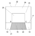
- FIG. 4 is a diagram showing the main surface 24 of the collar portion 13 of the magnetic core 11 in FIG.
- the surface of the collar portion 13 on the winding core portion 12 side is represented as the main surface 24.
- the region of the surface where the winding core portion 12 and the flange portion 13 intersect on the main surface 24 is represented as the central region 25.
- the region other than the central region 25 is the peripheral region 26.
- the region where the recess 20 is provided is the first region 18, and the region extending from the recess 20 to both outer portions is the second region 19.
- FIG. 5 is a partially enlarged perspective view of the magnetic core 11 including the region A in FIG.
- the intersection of the side line Le of the winding core portion 12 and the main surface 24 of the flange portion 13 on the mounting surface 21 side is the intersection B, and the other side line of the winding core portion 12 and the main surface 24 of the collar portion 13 Let the intersection be the intersection C.
- Lf be a straight line passing through the intersection B and the intersection C.
- the first region 18 and the second region 19 are on the front side (mounting surface side) of the straight line Lf. That is, the first region 18 and the second region 19 extend in the front direction from the central region 25 (not shown in FIG. 5) when viewed from the mounting surface 21.
- the winding 15 without looseness can be obtained. Therefore, it is necessary to provide the recess 20 in the portion of the line (line segment BC) where the winding core portion 12 and the flange portion 13 intersect.
- the second region 19 in which the recess 20 is not provided needs to be provided on the mounting surface side of the wire portion (line segment BC) where the winding core portion 12 and the flange portion 13 intersect. This is because without the second region 19, the winding 15 cannot be supported on the mounting surface side of the wire portion (line segment BC) where the winding core portion 12 and the flange portion 13 intersect, and the winding 15 cannot be supported. This is because it will loosen.
- the depth of the recess 20 is at least half the wire diameter of the winding 15.
- the depth of the recess 20 is made too deep, the strength of the flange portion 13 becomes weak, so it is desirable that the depth of the recess 20 is less than half the thickness of the second region 19. Further, it is more preferable that the depth of the recess 20 is not less than the wire diameter of the winding 15 and not more than a quarter of the thickness of the second region 19.
- the concave portion 20 has a tapered shape in which the thickness becomes thinner as the distance from the winding core portion 12 increases.
- the thickness of the first region 18 near the mounting surface 21 is set to be about 0.03 mm thinner than the thickness of the first region 18 near the winding core portion 12, and this period changes linearly.
- a taper is provided so as to.
- the second region 19 is in a parallel state without providing this taper.
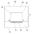
- FIG. 6 schematically shows the side surface of the common mode choke coil 10 according to the modified example.
- the magnetic core 11, the winding core portion 12, the flange portion 13, and the winding 15 are common as the common mode choke coil 10.
- the winding core portion 12 has a columnar shape, which is common to each modification. Therefore, in the following modification, the shape of the main surface of the collar portion 13 will be described.
- the central region 25 and the peripheral region 26 of the main surface of the collar portion 13 are common.
- the intersection point B, the intersection point C, and the straight line Lf are also common, they are shown only and will not be described in detail.
- the recess 20 is also common, it is shown only if it is not necessary.
- the first region 18 has a line segment BC on one side, and the second region 19 is adjacent to the first region 18. Further, the first region 18 and the second region 19 are provided in the direction toward the mounting surface 21 with the straight line Lf as a boundary.
- the common mode choke coil 10 in the first modified example uses a square columnar winding core portion 12 similar to that shown in FIG. As shown in FIG. 7, the first region 18 on the main surface of the collar portion 13 has a trapezoidal shape that expands from the central region 25 toward the mounting surface 21. Both the first region 18 and the second region are in contact with the mounting surface 21.
- the common mode choke coil 10 in this first modification has the same effect as the common mode choke coil 10 according to the above embodiment.
- the common mode choke coil 10 in the second modified example uses a square columnar winding core portion 12 similar to that shown in FIG. As shown in FIG. 8, the first region 18 on the main surface of the collar portion 13 has a narrow trapezoidal shape from the central region 25 toward the mounting surface 21. Both the first region 18 and the second region are in contact with the mounting surface 21.
- the common mode choke coil 10 in this second modification has the same effect as the common mode choke coil 10 according to the above embodiment.
- the common mode choke coil 10 of the first modification and the second modification is compared with the common mode choke coil 10 of the above embodiment having the rectangular first region 18 shown in FIG.
- the rectangular first region 18 in the above embodiment has a larger area of the second region 19 than the first region 18 in the first modification. Therefore, the rectangular first region 18 in the above embodiment can have a wider region for supporting the winding 15 than the first region 18 in the first modification. Therefore, the common mode choke coil 10 according to the above embodiment can further prevent loosening of the winding 15 as compared with the common mode choke coil 10 according to the first modification.
- the rectangular first region 18 in the above embodiment can make the area of the second region 19 near the intersection B and the intersection C smaller than that of the first region 18 in the second modification. Therefore, the rectangular first region 18 in the above embodiment is affected by the swelling 23 due to the joining between the winding core portion 12 supporting the winding 15 and the flange portion 13 as compared with the first region 18 in the second modification. Can be smaller. Therefore, the rectangular first region 18 in the above embodiment can reduce the lift of the winding 15 as compared with the first region 18 in the second modification. As a result, the common mode choke coil 10 according to the above embodiment can further prevent loosening of the winding 15 as compared with the common mode choke coil 10 according to the second modification.
- the rectangular first region 18 in the above embodiment is optimal.
- the rectangular first region 18 is a region in which the line segment BC is projected toward the mounting surface 21 when viewed from a direction perpendicular to the main surface 24 (second region 19).
- the common mode choke coil 10 in the third modified example uses a square columnar winding core portion 12 similar to that shown in FIG. As shown in FIG. 9, the first region 18 on the main surface of the collar portion 13 has a recess 20 which is a rectangular groove along the line segment BC.
- the common mode choke coil 10 in this third modification has the same effect as the common mode choke coil 10 according to the above embodiment.
- the depth of the recess 20 is at least half the wire diameter of the winding 15.
- the depth of the recess 20 is made too deep, the strength of the flange portion 13 becomes weak, so it is desirable that the depth of the recess 20 is less than half the thickness of the second region 19.
- the depth of the recess 20 is not less than the wire diameter of the winding 15 and not more than a quarter of the thickness of the second region 19.
- the width of the recess 20 in the direction toward the mounting surface 21 is preferably equal to or larger than the thickness of the winding 15.
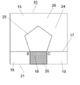
- the common mode choke coil 10 in the fourth modified example uses a winding core portion 12 of a pentagonal prism. As shown in FIG. 10, in the main surface of the collar portion 13, the first region 18 has a rectangular recess 20 along the line segment BC which is one side of the pentagon.
- the common mode choke coil 10 in the fourth modification has the same effect as the common mode choke coil 10 according to the above embodiment.
- a triangular prism or a prism having a hexagonal or more angle can be used as the winding core portion 12.
- the common mode choke coil 10 in the fifth modification uses a cylindrical winding core portion 12 having a surface including the line segment BC as a notch portion. As shown in FIG. 11, the first region 18 on the main surface of the collar portion 13 has a rectangular recess 20 along the line segment BC which is a notch portion.
- the common mode choke coil 10 in the fifth modification has the same effect as the common mode choke coil 10 according to the above embodiment.
- a column having an elliptical cross section whose cutout portion is the surface including the line segment BC may be used, and the line segment BC may be used in addition to the ellipse.
- a cylinder having a closed curved cross section having a cutout portion on the including surface may be used.
- the common mode choke coil according to the present disclosure is industrially useful because it can prevent loosening of windings and can obtain a common mode choke coil having excellent mode conversion characteristics.
Landscapes
- Engineering & Computer Science (AREA)
- Power Engineering (AREA)
- Microelectronics & Electronic Packaging (AREA)
- Coils Or Transformers For Communication (AREA)
Abstract
L'invention concerne une bobine d'arrêt en mode commun qui empêche le desserrage d'un enroulement et présente des caractéristiques de conversion de mode supérieures. La bobine d'arrêt en mode commun comprend : un noyau magnétique (11) ; des électrodes externes (17) ; une paire d'enroulements (15) ; et une plaque magnétique (14). Le noyau magnétique (11) a une partie de noyau d'enroulement (12) et une paire de parties de bride (13) disposées aux deux extrémités de la partie de noyau d'enroulement (12). Les électrodes externes (17) sont formées sur les parties de bride (13). Les enroulements (15) sont enroulés autour de la partie de noyau d'enroulement (12) et ont des extrémités de ceux-ci menant vers les électrodes externes (17). La plaque magnétique (14) est liée à la paire de parties de bride (13) avec un adhésif. Une région des parties de bride (13) à partir de la partie de noyau d'enroulement (12) vers des surfaces de montage (21) comprend une première région à partir d'un plan où la partie de noyau d'enroulement (12) et les parties de bride (13) se croisent vers les surfaces de montage (21), et une seconde région espacée de plus de la partie de noyau d'enroulement (12) que la première région, l'épaisseur de la première région étant rendue plus petite que l'épaisseur de la seconde région.
Priority Applications (1)
| Application Number | Priority Date | Filing Date | Title |
|---|---|---|---|
| JP2021527457A JPWO2020255593A1 (fr) | 2019-06-19 | 2020-05-13 |
Applications Claiming Priority (2)
| Application Number | Priority Date | Filing Date | Title |
|---|---|---|---|
| JP2019113292 | 2019-06-19 | ||
| JP2019-113292 | 2019-06-19 |
Publications (1)
| Publication Number | Publication Date |
|---|---|
| WO2020255593A1 true WO2020255593A1 (fr) | 2020-12-24 |
Family
ID=74037459
Family Applications (1)
| Application Number | Title | Priority Date | Filing Date |
|---|---|---|---|
| PCT/JP2020/019152 WO2020255593A1 (fr) | 2019-06-19 | 2020-05-13 | Bobine d'arrêt en mode commun |
Country Status (2)
| Country | Link |
|---|---|
| JP (1) | JPWO2020255593A1 (fr) |
| WO (1) | WO2020255593A1 (fr) |
Citations (3)
| Publication number | Priority date | Publication date | Assignee | Title |
|---|---|---|---|---|
| JPH0444109U (fr) * | 1990-08-21 | 1992-04-15 | ||
| JP2000150282A (ja) * | 1998-11-12 | 2000-05-30 | Taiyo Yuden Co Ltd | チップ状コイル用コア及びその製造方法 |
| JP2012028684A (ja) * | 2010-07-27 | 2012-02-09 | Tdk Corp | コモンモードフィルタ |
-
2020
- 2020-05-13 JP JP2021527457A patent/JPWO2020255593A1/ja active Pending
- 2020-05-13 WO PCT/JP2020/019152 patent/WO2020255593A1/fr active Application Filing
Patent Citations (3)
| Publication number | Priority date | Publication date | Assignee | Title |
|---|---|---|---|---|
| JPH0444109U (fr) * | 1990-08-21 | 1992-04-15 | ||
| JP2000150282A (ja) * | 1998-11-12 | 2000-05-30 | Taiyo Yuden Co Ltd | チップ状コイル用コア及びその製造方法 |
| JP2012028684A (ja) * | 2010-07-27 | 2012-02-09 | Tdk Corp | コモンモードフィルタ |
Also Published As
| Publication number | Publication date |
|---|---|
| JPWO2020255593A1 (fr) | 2020-12-24 |
Similar Documents
| Publication | Publication Date | Title |
|---|---|---|
| US20210125772A1 (en) | Common mode filter | |
| US20210241960A1 (en) | Inductor component | |
| US10090096B2 (en) | Common mode choke coil | |
| JP6303123B2 (ja) | コモンモードノイズフィルタ | |
| US20130186995A1 (en) | Core for wire-wound component and manufacturing method thereof and wire-wound component made therewith | |
| JP6569653B2 (ja) | 巻線型コイル部品 | |
| JP2017112156A (ja) | コモンモードチョークコイル | |
| JP6598168B2 (ja) | コイル部品 | |
| US11842839B2 (en) | Magnetic coupling coil component | |
| US6498553B1 (en) | Laminated type inductor | |
| WO2018029998A1 (fr) | Bobine d'induction en mode commun et son procédé de fabrication | |
| JP2019050318A (ja) | ドラム状コアおよびコイル部品 | |
| JP6202165B2 (ja) | コモンモードフィルタ | |
| US20190392973A1 (en) | Coil component | |
| JP6336155B2 (ja) | コモンモードフィルタ | |
| WO2020255593A1 (fr) | Bobine d'arrêt en mode commun | |
| JP6563073B2 (ja) | コモンモードフィルタ | |
| JP2003124027A (ja) | コモンモードチョークコイル及びコモンモードチョークコイルのコモンモードインピーダンス調整方法 | |
| JP7182037B2 (ja) | コモンモードノイズフィルタ | |
| JP2009021325A (ja) | 巻線型コモンモードチョークコイル | |
| JPWO2020110692A1 (ja) | コモンモードノイズフィルタ | |
| JP5996007B2 (ja) | コモンモードフィルタ | |
| JP7270122B2 (ja) | コモンモードチョークコイル | |
| JP2009182055A (ja) | コモンモードチョークコイル | |
| US20230290561A1 (en) | Multilayer coil component |
Legal Events
| Date | Code | Title | Description |
|---|---|---|---|
| 121 | Ep: the epo has been informed by wipo that ep was designated in this application |
Ref document number: 20826931 Country of ref document: EP Kind code of ref document: A1 |
|
| ENP | Entry into the national phase |
Ref document number: 2021527457 Country of ref document: JP Kind code of ref document: A |
|
| NENP | Non-entry into the national phase |
Ref country code: DE |
|
| 122 | Ep: pct application non-entry in european phase |
Ref document number: 20826931 Country of ref document: EP Kind code of ref document: A1 |