WO2020255593A1 - Common-mode choke coil - Google Patents
Common-mode choke coil Download PDFInfo
- Publication number
- WO2020255593A1 WO2020255593A1 PCT/JP2020/019152 JP2020019152W WO2020255593A1 WO 2020255593 A1 WO2020255593 A1 WO 2020255593A1 JP 2020019152 W JP2020019152 W JP 2020019152W WO 2020255593 A1 WO2020255593 A1 WO 2020255593A1
- Authority
- WO
- WIPO (PCT)
- Prior art keywords
- region
- choke coil
- mode choke
- thickness
- pair
- Prior art date
Links
- 238000004804 winding Methods 0.000 claims abstract description 106
- 230000002093 peripheral effect Effects 0.000 claims description 14
- 238000006243 chemical reaction Methods 0.000 abstract description 6
- 239000000853 adhesive Substances 0.000 abstract description 2
- 230000001070 adhesive effect Effects 0.000 abstract description 2
- 230000004048 modification Effects 0.000 description 27
- 238000012986 modification Methods 0.000 description 27
- 230000000694 effects Effects 0.000 description 7
- 238000004891 communication Methods 0.000 description 4
- 229910000859 α-Fe Inorganic materials 0.000 description 4
- 239000011230 binding agent Substances 0.000 description 3
- 238000000465 moulding Methods 0.000 description 3
- 239000000843 powder Substances 0.000 description 3
- 230000008961 swelling Effects 0.000 description 3
- 238000010586 diagram Methods 0.000 description 2
- RYGMFSIKBFXOCR-UHFFFAOYSA-N Copper Chemical compound [Cu] RYGMFSIKBFXOCR-UHFFFAOYSA-N 0.000 description 1
- 238000010304 firing Methods 0.000 description 1
- 230000035699 permeability Effects 0.000 description 1
- 230000005855 radiation Effects 0.000 description 1
- 238000005245 sintering Methods 0.000 description 1
- 238000005476 soldering Methods 0.000 description 1
- 230000001629 suppression Effects 0.000 description 1
Images


Classifications
-
- H—ELECTRICITY
- H01—ELECTRIC ELEMENTS
- H01F—MAGNETS; INDUCTANCES; TRANSFORMERS; SELECTION OF MATERIALS FOR THEIR MAGNETIC PROPERTIES
- H01F17/00—Fixed inductances of the signal type
- H01F17/04—Fixed inductances of the signal type with magnetic core
-
- H—ELECTRICITY
- H01—ELECTRIC ELEMENTS
- H01F—MAGNETS; INDUCTANCES; TRANSFORMERS; SELECTION OF MATERIALS FOR THEIR MAGNETIC PROPERTIES
- H01F27/00—Details of transformers or inductances, in general
- H01F27/28—Coils; Windings; Conductive connections
-
- H—ELECTRICITY
- H01—ELECTRIC ELEMENTS
- H01F—MAGNETS; INDUCTANCES; TRANSFORMERS; SELECTION OF MATERIALS FOR THEIR MAGNETIC PROPERTIES
- H01F27/00—Details of transformers or inductances, in general
- H01F27/28—Coils; Windings; Conductive connections
- H01F27/29—Terminals; Tapping arrangements for signal inductances
Definitions
- the present disclosure relates to a common mode choke coil provided with a core and a wire, and particularly to a common mode choke coil suitable for use in a common mode filter for removing noise.
- Such a conventional common mode choke coil has a ferrite magnetic core in which flanges are formed on both sides of the winding core, and a plurality of turns wound on the winding core of the magnetic core by a bifilar winding or the like for several turns to several tens of turns. It is composed of a wire made of an insulating coated copper wire, a flange portion provided on both of the magnetic core having a magnetic permeability substantially the same as that of the magnetic core, and a magnetic plate arranged on the collar portion.
- the magnetic core and the magnetic plate are obtained by mixing a binder with ferrite powder, press-molding, and firing this.
- a plurality of electrodes are formed on both flanges or one flange, and the end of the wire winding start and the end of the winding end are conductively connected to these electrodes by soldering, thermocompression bonding, etc., respectively. Has been done. Then, in such a common mode choke coil, a desired impedance value is obtained by appropriately setting the number of windings of the wire wound around the core of the core.
- Patent Document 1 As the prior art document information related to the invention of this application, for example, Patent Document 1 is known.
- the invention according to the present disclosure has the following configurations in order to solve the above problems.
- the common mode choke coil of the present disclosure includes a magnetic core, a pair of external electrodes, two windings, and a magnetic plate.
- the magnetic core has a winding core portion and a pair of collar portions.
- the winding core portion has a columnar shape extending in the first direction.
- Each of the pair of collar portions is provided at both ends of the winding core portion.
- Each of the pair of collars is provided with a main surface and a mounting surface.
- a pair of external electrodes are provided on each of the pair of collar portions.
- the two windings are wound around the core.
- the magnetic plate is joined to the surface of the pair of collars opposite to the mounting surface. One end of each of the two windings is joined to one of a pair of external electrodes provided on one of the pair of collars.
- each of the two windings is joined to the other of a pair of external electrodes provided on the other of the pair of collars.
- the main surface of each of the pair of collars has a central region and a peripheral region.
- the central region is a region in contact with the core portion.
- the peripheral area is an area arranged around the central area.
- the peripheral region has a first region and a second region.
- the first region is in contact with the central region and extends from the central region toward the mounting surface.
- the second region is adjacent to the first region. Further, the second region extends in the front direction from the central region when viewed from the mounting surface.
- the thickness of the first region in the first direction is thinner than the thickness of the second region.
- the common mode choke coil of the first aspect of the present disclosure includes a magnetic core, a pair of external electrodes, two windings, and a magnetic plate.
- the magnetic core has a winding core portion and a pair of collar portions.
- the winding core portion has a columnar shape extending in the first direction.
- Each of the pair of collar portions is provided at both ends of the winding core portion.
- Each of the pair of collars is provided with a main surface and a mounting surface.
- a pair of external electrodes are provided on each of the pair of collar portions.
- the two windings are wound around the core.
- the magnetic plate is joined to the surface of the pair of collars opposite to the mounting surface.
- each of the two windings is joined to one of a pair of external electrodes provided on one of the pair of collars.
- the other end of each of the two windings is joined to the other of a pair of external electrodes provided on the other of the pair of collars.
- the main surface of each of the pair of collars has a central region and a peripheral region.
- the central region is a region in contact with the core portion.
- the peripheral area is an area arranged around the central area.
- the peripheral region has a first region and a second region.
- the first region is in contact with the central region and extends from the central region toward the mounting surface.
- the second region is adjacent to the first region. Further, the second region extends in the front direction from the central region when viewed from the mounting surface.
- the thickness of the first region in the first direction is thinner than the thickness of the second region.
- the thickness of the collar portion in the first region is set to be larger than the thickness of the collar portion in the second region by providing a recess in the first region for the first aspect. Also thin.
- the winding wire is obtained by subtracting the thickness of the collar portion in the first region from the thickness of the collar portion in the second region in the second aspect. It is set to be at least half the diameter and at least half the thickness of the collar in the second region.
- the winding wire is obtained by subtracting the thickness of the collar portion in the first region from the thickness of the collar portion in the second region in the third aspect. It is set to be equal to or larger than the diameter and less than a quarter of the thickness in the second region of the collar.
- the recess of the second aspect has a tapered shape in which the thickness of the collar portion in the first region becomes thinner as the distance from the winding core portion increases.
- the common mode choke coil of the sixth aspect of the present disclosure includes a side forming a peripheral region and the side surface of the winding core portion is a flat surface for the first aspect, and the angle formed by the flat surface and the second region is 90 degrees. Is.
- FIG. 1 is a side view of the common mode choke coil according to the embodiment of the present disclosure.
- FIG. 2 is a schematic cross-sectional view taken along line II-II of the common mode choke coil of FIG.
- FIG. 3 is a side view of a magnetic core used in the common mode choke coil of the embodiment of the present disclosure.
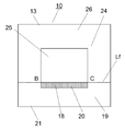
- FIG. 4 is a diagram showing the main surface of the collar portion of the magnetic core in FIG.
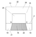
- FIG. 5 is a partially enlarged perspective view of the magnetic core shown in FIG.
- the magnetic core 11 is composed of a winding core portion 12 having a square pillar shape and a pair of flange portions 13 provided at both ends of the winding core portion 12.
- the winding 15 is formed by winding a pair of lead wires 15a and lead wires 15b that are insulatingly coated on 12.
- the ends of the lead wires 15a and 15b are joined on both sides to form the end 15c and the end 15d.
- the end portion 15c and the end portion 15d are electrically connected to each of the two external electrodes 17 provided on each of the pair of collar portions 13.
- a magnetic plate 14 is bonded to the upper part of the pair of collars 13 with an adhesive (not shown).
- This common mode choke coil is about 3.2 mm in length (direction of winding core), about 2.5 mm in width, and about 2.2 mm in height.
- the thickness of the magnetic plate 14 is about 0.6 mm.
- the winding 15 uses an insulating coated conductive wire having a diameter of about 0.05 mm.
- the surface opposite to the magnetic plate 14 is the mounting surface 21.
- the collar portion 13 has a width of about 2.5 mm, a height of about 1.6 mm, and a maximum thickness of about 0.6 mm.
- a recess 20 is provided on the surface of the flange portion 13 on the winding core portion 12 side, which is recessed by about 0.06 mm from the periphery on the mounting surface 21 side from the surface where the winding core portion 12 and the collar portion 13 intersect.
- the region where the recess 20 is provided is referred to as a first region 18, and both outer portions from the recess 20 are referred to as a second region 19. That is, in the second region 19, the thickness of the flange portion 13 is the largest, which is about 0.6 mm.
- the thickness of the first region 18 is about 0.06 mm thinner than the thickness of the second region 19.
- FIG. 2 is a schematic cross-sectional view taken along line II-II of FIG. 1 of the magnetic core 11 used in the common mode choke coil according to the embodiment of the present disclosure. That is, FIG.
- the line segment L is a region of the flange portion 13 including the joint surface between the winding core portion 12 and the flange portion 13 from the joint surface toward the mounting surface 21, and is in contact with the edge of the joint surface and the mounting surface 21. It is a perpendicular line extending to the side with respect to the mounting surface 21.
- the first region 18 and the second region 19 are defined with this L1 as a boundary.
- such a magnetic core 11 is obtained by mixing ferrite powder with a binder, press-molding it, and sintering it.
- press molding is performed using a mold, but the connecting portion 22 between the flange portion 13 and the winding core portion 12 does not have a perfect right angle, and the connecting portion 22 rises a little to generate a bulge 23, which is usually 0.
- a recess 20 recessed about 0.06 mm from the periphery is provided on the mounting surface 21 side from the line where the winding core portion 12 and the flange portion 13 intersect. Therefore, as shown in FIG. 3, the portion where the winding core portion 12 and the flange portion 13 on the mounting surface 21 side are connected (region A in FIG. 3) does not become a curved surface when viewed from the side surface, as shown in FIG. It can have corners and be in a substantially orthogonal state. I will explain this a little more.
- FIG. 3 is a side view of the magnetic core 11 used in the common mode choke coil of the present embodiment.
- the region A shows a portion where the winding core portion 12 and the flange portion 13 on the mounting surface 21 side are connected.
- FIG. 4 is a diagram showing the main surface 24 of the collar portion 13 of the magnetic core 11 in FIG.
- the surface of the collar portion 13 on the winding core portion 12 side is represented as the main surface 24.
- the region of the surface where the winding core portion 12 and the flange portion 13 intersect on the main surface 24 is represented as the central region 25.
- the region other than the central region 25 is the peripheral region 26.
- the region where the recess 20 is provided is the first region 18, and the region extending from the recess 20 to both outer portions is the second region 19.
- FIG. 5 is a partially enlarged perspective view of the magnetic core 11 including the region A in FIG.
- the intersection of the side line Le of the winding core portion 12 and the main surface 24 of the flange portion 13 on the mounting surface 21 side is the intersection B, and the other side line of the winding core portion 12 and the main surface 24 of the collar portion 13 Let the intersection be the intersection C.
- Lf be a straight line passing through the intersection B and the intersection C.
- the first region 18 and the second region 19 are on the front side (mounting surface side) of the straight line Lf. That is, the first region 18 and the second region 19 extend in the front direction from the central region 25 (not shown in FIG. 5) when viewed from the mounting surface 21.
- the winding 15 without looseness can be obtained. Therefore, it is necessary to provide the recess 20 in the portion of the line (line segment BC) where the winding core portion 12 and the flange portion 13 intersect.
- the second region 19 in which the recess 20 is not provided needs to be provided on the mounting surface side of the wire portion (line segment BC) where the winding core portion 12 and the flange portion 13 intersect. This is because without the second region 19, the winding 15 cannot be supported on the mounting surface side of the wire portion (line segment BC) where the winding core portion 12 and the flange portion 13 intersect, and the winding 15 cannot be supported. This is because it will loosen.
- the depth of the recess 20 is at least half the wire diameter of the winding 15.
- the depth of the recess 20 is made too deep, the strength of the flange portion 13 becomes weak, so it is desirable that the depth of the recess 20 is less than half the thickness of the second region 19. Further, it is more preferable that the depth of the recess 20 is not less than the wire diameter of the winding 15 and not more than a quarter of the thickness of the second region 19.
- the concave portion 20 has a tapered shape in which the thickness becomes thinner as the distance from the winding core portion 12 increases.
- the thickness of the first region 18 near the mounting surface 21 is set to be about 0.03 mm thinner than the thickness of the first region 18 near the winding core portion 12, and this period changes linearly.
- a taper is provided so as to.
- the second region 19 is in a parallel state without providing this taper.
- FIG. 6 schematically shows the side surface of the common mode choke coil 10 according to the modified example.
- the magnetic core 11, the winding core portion 12, the flange portion 13, and the winding 15 are common as the common mode choke coil 10.
- the winding core portion 12 has a columnar shape, which is common to each modification. Therefore, in the following modification, the shape of the main surface of the collar portion 13 will be described.
- the central region 25 and the peripheral region 26 of the main surface of the collar portion 13 are common.
- the intersection point B, the intersection point C, and the straight line Lf are also common, they are shown only and will not be described in detail.
- the recess 20 is also common, it is shown only if it is not necessary.
- the first region 18 has a line segment BC on one side, and the second region 19 is adjacent to the first region 18. Further, the first region 18 and the second region 19 are provided in the direction toward the mounting surface 21 with the straight line Lf as a boundary.
- the common mode choke coil 10 in the first modified example uses a square columnar winding core portion 12 similar to that shown in FIG. As shown in FIG. 7, the first region 18 on the main surface of the collar portion 13 has a trapezoidal shape that expands from the central region 25 toward the mounting surface 21. Both the first region 18 and the second region are in contact with the mounting surface 21.
- the common mode choke coil 10 in this first modification has the same effect as the common mode choke coil 10 according to the above embodiment.
- the common mode choke coil 10 in the second modified example uses a square columnar winding core portion 12 similar to that shown in FIG. As shown in FIG. 8, the first region 18 on the main surface of the collar portion 13 has a narrow trapezoidal shape from the central region 25 toward the mounting surface 21. Both the first region 18 and the second region are in contact with the mounting surface 21.
- the common mode choke coil 10 in this second modification has the same effect as the common mode choke coil 10 according to the above embodiment.
- the common mode choke coil 10 of the first modification and the second modification is compared with the common mode choke coil 10 of the above embodiment having the rectangular first region 18 shown in FIG.
- the rectangular first region 18 in the above embodiment has a larger area of the second region 19 than the first region 18 in the first modification. Therefore, the rectangular first region 18 in the above embodiment can have a wider region for supporting the winding 15 than the first region 18 in the first modification. Therefore, the common mode choke coil 10 according to the above embodiment can further prevent loosening of the winding 15 as compared with the common mode choke coil 10 according to the first modification.
- the rectangular first region 18 in the above embodiment can make the area of the second region 19 near the intersection B and the intersection C smaller than that of the first region 18 in the second modification. Therefore, the rectangular first region 18 in the above embodiment is affected by the swelling 23 due to the joining between the winding core portion 12 supporting the winding 15 and the flange portion 13 as compared with the first region 18 in the second modification. Can be smaller. Therefore, the rectangular first region 18 in the above embodiment can reduce the lift of the winding 15 as compared with the first region 18 in the second modification. As a result, the common mode choke coil 10 according to the above embodiment can further prevent loosening of the winding 15 as compared with the common mode choke coil 10 according to the second modification.
- the rectangular first region 18 in the above embodiment is optimal.
- the rectangular first region 18 is a region in which the line segment BC is projected toward the mounting surface 21 when viewed from a direction perpendicular to the main surface 24 (second region 19).
- the common mode choke coil 10 in the third modified example uses a square columnar winding core portion 12 similar to that shown in FIG. As shown in FIG. 9, the first region 18 on the main surface of the collar portion 13 has a recess 20 which is a rectangular groove along the line segment BC.
- the common mode choke coil 10 in this third modification has the same effect as the common mode choke coil 10 according to the above embodiment.
- the depth of the recess 20 is at least half the wire diameter of the winding 15.
- the depth of the recess 20 is made too deep, the strength of the flange portion 13 becomes weak, so it is desirable that the depth of the recess 20 is less than half the thickness of the second region 19.
- the depth of the recess 20 is not less than the wire diameter of the winding 15 and not more than a quarter of the thickness of the second region 19.
- the width of the recess 20 in the direction toward the mounting surface 21 is preferably equal to or larger than the thickness of the winding 15.
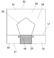
- the common mode choke coil 10 in the fourth modified example uses a winding core portion 12 of a pentagonal prism. As shown in FIG. 10, in the main surface of the collar portion 13, the first region 18 has a rectangular recess 20 along the line segment BC which is one side of the pentagon.
- the common mode choke coil 10 in the fourth modification has the same effect as the common mode choke coil 10 according to the above embodiment.
- a triangular prism or a prism having a hexagonal or more angle can be used as the winding core portion 12.
- the common mode choke coil 10 in the fifth modification uses a cylindrical winding core portion 12 having a surface including the line segment BC as a notch portion. As shown in FIG. 11, the first region 18 on the main surface of the collar portion 13 has a rectangular recess 20 along the line segment BC which is a notch portion.
- the common mode choke coil 10 in the fifth modification has the same effect as the common mode choke coil 10 according to the above embodiment.
- a column having an elliptical cross section whose cutout portion is the surface including the line segment BC may be used, and the line segment BC may be used in addition to the ellipse.
- a cylinder having a closed curved cross section having a cutout portion on the including surface may be used.
- the common mode choke coil according to the present disclosure is industrially useful because it can prevent loosening of windings and can obtain a common mode choke coil having excellent mode conversion characteristics.
Abstract
Provided is a common-mode choke coil that prevents loosening of winding and has superior mode conversion characteristics. The common mode choke coil comprises: a magnetic core (11); external electrodes (17); a pair of windings (15); and a magnetic plate (14). The magnetic core (11) has a winding core portion (12) and a pair of flange portions (13) provided at both ends of the winding core portion (12). The external electrodes (17) are formed on the flange portions (13). The windings (15) are wound around the winding core portion (12) and have ends thereof leading out to the external electrodes (17). The magnetic plate (14) is bonded to the pair of flange portions (13) with an adhesive. A region of the flange portions (13) from the winding core portion (12) toward mounting surfaces (21) includes a first region from a plane where the winding core portion (12) and the flange portions (13) intersect toward the mounting surfaces (21), and a second region spaced apart more from the winding core portion (12) than the first region, wherein the thickness of the first region is made smaller than the thickness of the second region.
Description
本開示は、コアとワイヤとを備えたコモンモードチョークコイルに関し、特にノイズを除去するコモンモードフィルタに用いて好適なコモンモードチョークコイルに関する。
The present disclosure relates to a common mode choke coil provided with a core and a wire, and particularly to a common mode choke coil suitable for use in a common mode filter for removing noise.
近年自動車市場における電子化の動きは目覚ましく、1台あたりに搭載される電気機器の数はますます増加してきている。これらの通信に車載LAN(LAN:Local Area Network)が用いられ、大量の情報を伝達するために、高速化、通信品質の高信頼性が要求される。このため不要輻射ノイズ対策や高周波信号のコモンモードノイズ対策が必要となり、巻線型コモンモードチョークコイルが多く用いられている。
In recent years, the movement toward computerization in the automobile market has been remarkable, and the number of electric devices installed in each unit is increasing more and more. An in-vehicle LAN (LAN: Local Area Network) is used for these communications, and in order to transmit a large amount of information, high speed and high reliability of communication quality are required. Therefore, it is necessary to take measures against unnecessary radiation noise and common mode noise of high frequency signals, and winding type common mode choke coils are often used.
このような従来技術のコモンモードチョークコイルは、巻芯の両側に鍔部が形成されたフェライト磁性コアと、磁性コアの巻芯にバイファイラ巻等によって数ターン~数十ターン巻回された複数の絶縁被膜銅線からなるワイヤと、磁性コアとほぼ同じ透磁率を有し磁性コアの両方に設けられた鍔部と、鍔部の上に配置された磁性板とによって構成されている。磁性コアおよび磁性板はフェライト粉末に結合剤を混ぜてプレス成型し、これを焼成することによって得られる。さらに、両方の鍔部または一方の鍔部には複数の電極が形成され、ワイヤの巻始めの端部と巻終りの端部はこれらの電極に対してそれぞれ半田付け、熱圧着等によって導電接続されている。そして、このようなコモンモードチョークコイルでは、コアの巻芯に巻回するワイヤの巻回回数を適宜設定することによって所望のインピーダンス値を得ていた。
Such a conventional common mode choke coil has a ferrite magnetic core in which flanges are formed on both sides of the winding core, and a plurality of turns wound on the winding core of the magnetic core by a bifilar winding or the like for several turns to several tens of turns. It is composed of a wire made of an insulating coated copper wire, a flange portion provided on both of the magnetic core having a magnetic permeability substantially the same as that of the magnetic core, and a magnetic plate arranged on the collar portion. The magnetic core and the magnetic plate are obtained by mixing a binder with ferrite powder, press-molding, and firing this. Further, a plurality of electrodes are formed on both flanges or one flange, and the end of the wire winding start and the end of the winding end are conductively connected to these electrodes by soldering, thermocompression bonding, etc., respectively. Has been done. Then, in such a common mode choke coil, a desired impedance value is obtained by appropriately setting the number of windings of the wire wound around the core of the core.
なお、この出願の発明に関連する先行技術文献情報としては、例えば、特許文献1が知られている。
As the prior art document information related to the invention of this application, for example, Patent Document 1 is known.
しかしながら、従来多く用いられてきたCAN通信では通常のコモンモードチョークコイルで問題なかったが、さらに高速の車載イーサネット(Ethernet)通信では、モード変換特性の抑制等さらに高度な性能が要求されるようになる。しかしながら巻芯部に巻回された巻線がゆるむと1対の巻線間のインダクタンス値に差異が生じ、モード変換特性が劣化しやすくなる。
However, in CAN communication, which has been widely used in the past, there was no problem with a normal common mode choke coil, but in higher speed in-vehicle Ethernet communication, higher performance such as suppression of mode conversion characteristics is required. Become. However, if the winding wound around the winding core is loosened, the inductance value between the pair of windings will differ, and the mode conversion characteristics will easily deteriorate.
本開示に係る発明は上記問題を解決するために、以下の構成を備える。
The invention according to the present disclosure has the following configurations in order to solve the above problems.
すなわち、本開示のコモンモードチョークコイルは、磁性コアと、一対の外部電極と、2本の巻線と、磁性板と、を備える。磁性コアは、巻芯部と、一対の鍔部と、を有する。巻芯部は、第1の方向に延びる柱状の形状を有する。一対の鍔部の各々は、巻芯部の両端の各々に設けられている。一対の鍔部の各々には、主面と実装面とが設けられている。一対の外部電極は、一対の鍔部の各々に、各々設けられている。2本の巻線は、巻芯部に巻回される。磁性板は、一対の鍔部の実装面とは反対側の面に接合されている。2本の巻線の各々の一端は、一対の鍔部の一方に設けられた一対の外部電極の一方に接合される。2本の巻線の各々の他端は、一対の鍔部の他方に設けられた一対の外部電極の他方に接合される。一対の鍔部の各々が備える主面は、中央領域と、周辺領域とを有する。中央領域は、巻芯部と接する領域である。周辺領域は、中央領域の周囲に配置された領域である。周辺領域は、第1領域と、第2領域とを有する。第1領域は、中央領域に接し、中央領域から実装面に向かって延びる。第2領域は、第1領域に隣接する。また、第2領域は、実装面からみて中央領域より手前方向へ延びる。第1の方向における第1領域の厚さは、第2領域の厚さよりも薄い。
That is, the common mode choke coil of the present disclosure includes a magnetic core, a pair of external electrodes, two windings, and a magnetic plate. The magnetic core has a winding core portion and a pair of collar portions. The winding core portion has a columnar shape extending in the first direction. Each of the pair of collar portions is provided at both ends of the winding core portion. Each of the pair of collars is provided with a main surface and a mounting surface. A pair of external electrodes are provided on each of the pair of collar portions. The two windings are wound around the core. The magnetic plate is joined to the surface of the pair of collars opposite to the mounting surface. One end of each of the two windings is joined to one of a pair of external electrodes provided on one of the pair of collars. The other end of each of the two windings is joined to the other of a pair of external electrodes provided on the other of the pair of collars. The main surface of each of the pair of collars has a central region and a peripheral region. The central region is a region in contact with the core portion. The peripheral area is an area arranged around the central area. The peripheral region has a first region and a second region. The first region is in contact with the central region and extends from the central region toward the mounting surface. The second region is adjacent to the first region. Further, the second region extends in the front direction from the central region when viewed from the mounting surface. The thickness of the first region in the first direction is thinner than the thickness of the second region.
上記構成により、巻線のゆるみを防止し、モード変換特性に優れたコモンモードチョークコイルを得ることができる。
With the above configuration, it is possible to prevent loosening of the winding and obtain a common mode choke coil with excellent mode conversion characteristics.
(1)本開示のコモンモードチョークコイルについて
本開示の第1の態様のコモンモードチョークコイルは、磁性コアと、一対の外部電極と、2本の巻線と、磁性板と、を備える。磁性コアは、巻芯部と、一対の鍔部と、を有する。巻芯部は、第1の方向に延びる柱状の形状を有する。一対の鍔部の各々は、巻芯部の両端の各々に設けられている。一対の鍔部の各々には、主面と実装面とが設けられている。一対の外部電極は、一対の鍔部の各々に、各々設けられている。2本の巻線は、巻芯部に巻回される。磁性板は、一対の鍔部の実装面とは反対側の面に接合されている。2本の巻線の各々の一端は、一対の鍔部の一方に設けられた一対の外部電極の一方に接合される。2本の巻線の各々の他端は、一対の鍔部の他方に設けられた一対の外部電極の他方に接合される。一対の鍔部の各々が備える主面は、中央領域と、周辺領域とを有する。中央領域は、巻芯部と接する領域である。周辺領域は、中央領域の周囲に配置された領域である。周辺領域は、第1領域と、第2領域とを有する。第1領域は、中央領域に接し、中央領域から実装面に向かって延びる。第2領域は、第1領域に隣接する。また、第2領域は、実装面からみて中央領域より手前方向へ延びる。第1の方向における第1領域の厚さは、第2領域の厚さよりも薄い。 (1) Common Mode Choke Coil of the Present Disclosure The common mode choke coil of the first aspect of the present disclosure includes a magnetic core, a pair of external electrodes, two windings, and a magnetic plate. The magnetic core has a winding core portion and a pair of collar portions. The winding core portion has a columnar shape extending in the first direction. Each of the pair of collar portions is provided at both ends of the winding core portion. Each of the pair of collars is provided with a main surface and a mounting surface. A pair of external electrodes are provided on each of the pair of collar portions. The two windings are wound around the core. The magnetic plate is joined to the surface of the pair of collars opposite to the mounting surface. One end of each of the two windings is joined to one of a pair of external electrodes provided on one of the pair of collars. The other end of each of the two windings is joined to the other of a pair of external electrodes provided on the other of the pair of collars. The main surface of each of the pair of collars has a central region and a peripheral region. The central region is a region in contact with the core portion. The peripheral area is an area arranged around the central area. The peripheral region has a first region and a second region. The first region is in contact with the central region and extends from the central region toward the mounting surface. The second region is adjacent to the first region. Further, the second region extends in the front direction from the central region when viewed from the mounting surface. The thickness of the first region in the first direction is thinner than the thickness of the second region.
本開示の第1の態様のコモンモードチョークコイルは、磁性コアと、一対の外部電極と、2本の巻線と、磁性板と、を備える。磁性コアは、巻芯部と、一対の鍔部と、を有する。巻芯部は、第1の方向に延びる柱状の形状を有する。一対の鍔部の各々は、巻芯部の両端の各々に設けられている。一対の鍔部の各々には、主面と実装面とが設けられている。一対の外部電極は、一対の鍔部の各々に、各々設けられている。2本の巻線は、巻芯部に巻回される。磁性板は、一対の鍔部の実装面とは反対側の面に接合されている。2本の巻線の各々の一端は、一対の鍔部の一方に設けられた一対の外部電極の一方に接合される。2本の巻線の各々の他端は、一対の鍔部の他方に設けられた一対の外部電極の他方に接合される。一対の鍔部の各々が備える主面は、中央領域と、周辺領域とを有する。中央領域は、巻芯部と接する領域である。周辺領域は、中央領域の周囲に配置された領域である。周辺領域は、第1領域と、第2領域とを有する。第1領域は、中央領域に接し、中央領域から実装面に向かって延びる。第2領域は、第1領域に隣接する。また、第2領域は、実装面からみて中央領域より手前方向へ延びる。第1の方向における第1領域の厚さは、第2領域の厚さよりも薄い。 (1) Common Mode Choke Coil of the Present Disclosure The common mode choke coil of the first aspect of the present disclosure includes a magnetic core, a pair of external electrodes, two windings, and a magnetic plate. The magnetic core has a winding core portion and a pair of collar portions. The winding core portion has a columnar shape extending in the first direction. Each of the pair of collar portions is provided at both ends of the winding core portion. Each of the pair of collars is provided with a main surface and a mounting surface. A pair of external electrodes are provided on each of the pair of collar portions. The two windings are wound around the core. The magnetic plate is joined to the surface of the pair of collars opposite to the mounting surface. One end of each of the two windings is joined to one of a pair of external electrodes provided on one of the pair of collars. The other end of each of the two windings is joined to the other of a pair of external electrodes provided on the other of the pair of collars. The main surface of each of the pair of collars has a central region and a peripheral region. The central region is a region in contact with the core portion. The peripheral area is an area arranged around the central area. The peripheral region has a first region and a second region. The first region is in contact with the central region and extends from the central region toward the mounting surface. The second region is adjacent to the first region. Further, the second region extends in the front direction from the central region when viewed from the mounting surface. The thickness of the first region in the first direction is thinner than the thickness of the second region.
本開示の第2の態様のコモンモードチョークコイルは、第1の態様について第1領域に凹部を設けることにより、第1領域での鍔部の厚さを第2領域での鍔部の厚さよりも薄くする。
In the common mode choke coil of the second aspect of the present disclosure, the thickness of the collar portion in the first region is set to be larger than the thickness of the collar portion in the second region by providing a recess in the first region for the first aspect. Also thin.
本開示の第3の態様のコモンモードチョークコイルは、第2の態様について第2領域での鍔部の厚さから第1領域での鍔部の厚さを減じた値を、巻線の線径の半分以上、第2領域での鍔部の厚さの半分以下としている。
In the common mode choke coil of the third aspect of the present disclosure, the winding wire is obtained by subtracting the thickness of the collar portion in the first region from the thickness of the collar portion in the second region in the second aspect. It is set to be at least half the diameter and at least half the thickness of the collar in the second region.
本開示の第4の態様のコモンモードチョークコイルは、第3の態様について第2領域での鍔部の厚さから第1領域での鍔部の厚さを減じた値を、巻線の線径以上、鍔部の第2領域での厚さの4分の1以下としている。
In the common mode choke coil of the fourth aspect of the present disclosure, the winding wire is obtained by subtracting the thickness of the collar portion in the first region from the thickness of the collar portion in the second region in the third aspect. It is set to be equal to or larger than the diameter and less than a quarter of the thickness in the second region of the collar.
本開示の第5の態様のコモンモードチョークコイルは、第2の態様について凹部は、巻芯部から離れるにしたがって第1領域での鍔部の厚さが薄くなるテーパ状になっている。
In the common mode choke coil of the fifth aspect of the present disclosure, the recess of the second aspect has a tapered shape in which the thickness of the collar portion in the first region becomes thinner as the distance from the winding core portion increases.
本開示の第6の態様のコモンモードチョークコイルは、第1の態様について周辺領域を形成する辺を含みかつ巻芯部の側面が平面であり、平面と第2領域とのなす角度が90度である。
The common mode choke coil of the sixth aspect of the present disclosure includes a side forming a peripheral region and the side surface of the winding core portion is a flat surface for the first aspect, and the angle formed by the flat surface and the second region is 90 degrees. Is.
(2)実施の形態
以下、本開示の一実施の形態におけるコモンモードチョークコイルについて、図面を参照しながら説明する。なお、以下に述べる構造や数値は本開示のコモンモードチョークコイルの一例であり、本開示のコモンモードチョークコイルは当該構造や数値に限定されるものではない。 (2) Embodiment Hereinafter, the common mode choke coil according to the embodiment of the present disclosure will be described with reference to the drawings. The structures and numerical values described below are examples of the common mode choke coils of the present disclosure, and the common mode choke coils of the present disclosure are not limited to the structures and numerical values.
以下、本開示の一実施の形態におけるコモンモードチョークコイルについて、図面を参照しながら説明する。なお、以下に述べる構造や数値は本開示のコモンモードチョークコイルの一例であり、本開示のコモンモードチョークコイルは当該構造や数値に限定されるものではない。 (2) Embodiment Hereinafter, the common mode choke coil according to the embodiment of the present disclosure will be described with reference to the drawings. The structures and numerical values described below are examples of the common mode choke coils of the present disclosure, and the common mode choke coils of the present disclosure are not limited to the structures and numerical values.
図1は本開示の一実施の形態におけるコモンモードチョークコイルの側面図である。図2は図1のコモンモードチョークコイルのII-II線断面見取図である。図3は本開示の一実施の形態のコモンモードチョークコイルに用いられる磁性コアの側面図である。図4は、図3における磁性コアの、鍔部の主面を示す図である。図5は、図3に示す磁性コアの一部拡大斜視図である。
FIG. 1 is a side view of the common mode choke coil according to the embodiment of the present disclosure. FIG. 2 is a schematic cross-sectional view taken along line II-II of the common mode choke coil of FIG. FIG. 3 is a side view of a magnetic core used in the common mode choke coil of the embodiment of the present disclosure. FIG. 4 is a diagram showing the main surface of the collar portion of the magnetic core in FIG. FIG. 5 is a partially enlarged perspective view of the magnetic core shown in FIG.
本開示のコモンモードチョークコイル10において、磁性コア11は四角柱の形状を有する巻芯部12及びこの巻芯部12の両端部に設けられた1対の鍔部13からなり、この巻芯部12に絶縁被覆された1対の導線15a、導線15bが巻回されることによって巻線15を構成している。それぞれの導線15a、導線15bの端部が両側で接合されて端部15c、端部15dが形成される。端部15c、端部15dは一対の鍔部13のそれぞれに設けられた、2つの外部電極17のそれぞれに電気的に接続されている。
In the common mode choke coil 10 of the present disclosure, the magnetic core 11 is composed of a winding core portion 12 having a square pillar shape and a pair of flange portions 13 provided at both ends of the winding core portion 12. The winding 15 is formed by winding a pair of lead wires 15a and lead wires 15b that are insulatingly coated on 12. The ends of the lead wires 15a and 15b are joined on both sides to form the end 15c and the end 15d. The end portion 15c and the end portion 15d are electrically connected to each of the two external electrodes 17 provided on each of the pair of collar portions 13.
1対の鍔部13の上部には磁性板14が接着剤(図示せず)により接合されている。
A magnetic plate 14 is bonded to the upper part of the pair of collars 13 with an adhesive (not shown).
このコモンモードチョークコイルの大きさは、長さ(巻芯方向)約3.2mm、幅約2.5mm、高さ約2.2mmとなっている。磁性板14の厚さは約0.6mmとなっている。さらに巻線15は直径約0.05mmの絶縁被覆導線を用いている。また磁性板14とは反対側の面が実装面21となっている。
The size of this common mode choke coil is about 3.2 mm in length (direction of winding core), about 2.5 mm in width, and about 2.2 mm in height. The thickness of the magnetic plate 14 is about 0.6 mm. Further, the winding 15 uses an insulating coated conductive wire having a diameter of about 0.05 mm. The surface opposite to the magnetic plate 14 is the mounting surface 21.
鍔部13は幅約2.5mm、高さ約1.6mm、最大厚さが約0.6mmとなっている。鍔部13の巻芯部12側の面の、巻芯部12と鍔部13が交わる面から実装面21側に周辺よりも約0.06mm凹んだ凹部20が設けられている。ここで、凹部20が設けられている領域を第1領域18、凹部20から両外側部を第2領域19と称する。すなわち第2領域19では鍔部13の厚さの中で最大の厚さとなり、これが約0.6mmとなっている。これに対して第1領域18の厚さは、第2領域19の厚さに比べて約0.06mm薄くなっている。なお、ここでいう厚さは、図3および図5においてt1、t2で表される。すなわち、t1は第2領域19では鍔部13の厚さの中で最大の厚さであり、t1=約0.6mmである。また、t2は第1領域18の厚さであり、t2はt1より約0.06mm薄い。すなわち、t2=約0.54mmである。図2は、本開示の一実施の形態におけるコモンモードチョークコイルに用いられる磁性コア11の図1におけるII-II線断面見取図である。すなわち図2は、図1においてII-II線を含み紙面に垂直な面で切った断面図と、II-II線から延びる矢印方向に鍔部13をみたときの鍔部13の表面を同時に示した図である。図2において線分Lは、巻芯部12と鍔部13との接合面を含む鍔部13の面において、接合面より実装面21へ向かう領域で、接合面の縁に接しかつ実装面21側へ伸びる、実装面21に対する垂線である。このL1を境界として第1領域18および第2領域19が規定される。
The collar portion 13 has a width of about 2.5 mm, a height of about 1.6 mm, and a maximum thickness of about 0.6 mm. A recess 20 is provided on the surface of the flange portion 13 on the winding core portion 12 side, which is recessed by about 0.06 mm from the periphery on the mounting surface 21 side from the surface where the winding core portion 12 and the collar portion 13 intersect. Here, the region where the recess 20 is provided is referred to as a first region 18, and both outer portions from the recess 20 are referred to as a second region 19. That is, in the second region 19, the thickness of the flange portion 13 is the largest, which is about 0.6 mm. On the other hand, the thickness of the first region 18 is about 0.06 mm thinner than the thickness of the second region 19. The thickness referred to here is represented by t1 and t2 in FIGS. 3 and 5. That is, t1 is the maximum thickness of the collar portion 13 in the second region 19, and t1 = about 0.6 mm. Further, t2 is the thickness of the first region 18, and t2 is about 0.06 mm thinner than t1. That is, t2 = about 0.54 mm. FIG. 2 is a schematic cross-sectional view taken along line II-II of FIG. 1 of the magnetic core 11 used in the common mode choke coil according to the embodiment of the present disclosure. That is, FIG. 2 simultaneously shows a cross-sectional view taken along a plane perpendicular to the paper surface including the line II-II in FIG. 1 and the surface of the collar portion 13 when the collar portion 13 is viewed in the direction of the arrow extending from the line II-II. It is a figure. In FIG. 2, the line segment L is a region of the flange portion 13 including the joint surface between the winding core portion 12 and the flange portion 13 from the joint surface toward the mounting surface 21, and is in contact with the edge of the joint surface and the mounting surface 21. It is a perpendicular line extending to the side with respect to the mounting surface 21. The first region 18 and the second region 19 are defined with this L1 as a boundary.
通常このような磁性コア11は、フェライト粉体にバインダーを混ぜてプレス成型し、これを焼結させることにより得られる。このとき金型を用いてプレス成型を行うが、鍔部13と巻芯部12とのつなぎ部分22は、完全な直角にはならず、つなぎ部分22が少し盛り上がって盛り上がり23が生じ、通常0.1mm以上の曲率半径をもった曲面となる。このつなぎ部分22の4面全ての曲率半径が巻線15の線径の半分よりも大きくなると、巻線15をこのつなぎ部分22まで巻いたときに曲面にのりあげてしまう。その結果、巻線15のゆるみが発生しやすい。そのためモード変換特性等が劣化しやすくなる。
Normally, such a magnetic core 11 is obtained by mixing ferrite powder with a binder, press-molding it, and sintering it. At this time, press molding is performed using a mold, but the connecting portion 22 between the flange portion 13 and the winding core portion 12 does not have a perfect right angle, and the connecting portion 22 rises a little to generate a bulge 23, which is usually 0. A curved surface with a radius of curvature of 1 mm or more. If the radius of curvature of all four surfaces of the connecting portion 22 is larger than half the wire diameter of the winding 15, the winding 15 will be rolled up on a curved surface when it is wound up to the connecting portion 22. As a result, loosening of the winding 15 is likely to occur. Therefore, the mode conversion characteristics and the like are likely to deteriorate.
これに対して本実施の形態では、巻芯部12と鍔部13が交わる線から実装面21側に周辺よりも約0.06mm凹んだ凹部20が設けられている。そのため、図3のように側面から見たときに実装面21側の巻芯部12と鍔部13が接続する部分(図3における領域A)で曲面とはならず、図5に示すように角部を有してほぼ直交した状態とすることができる。このことをもう少し説明する。
On the other hand, in the present embodiment, a recess 20 recessed about 0.06 mm from the periphery is provided on the mounting surface 21 side from the line where the winding core portion 12 and the flange portion 13 intersect. Therefore, as shown in FIG. 3, the portion where the winding core portion 12 and the flange portion 13 on the mounting surface 21 side are connected (region A in FIG. 3) does not become a curved surface when viewed from the side surface, as shown in FIG. It can have corners and be in a substantially orthogonal state. I will explain this a little more.
図3は本実施形態のコモンモードチョークコイルに用いられる磁性コア11の側面図である。図3において領域Aは、実装面21側の巻芯部12と鍔部13が接続する部分を示す。
FIG. 3 is a side view of the magnetic core 11 used in the common mode choke coil of the present embodiment. In FIG. 3, the region A shows a portion where the winding core portion 12 and the flange portion 13 on the mounting surface 21 side are connected.
図4は、図3における磁性コア11の、鍔部13の主面24を示す図である。図4において、鍔部13の巻芯部12側の面は主面24として表される。また、主面24において巻芯部12と鍔部13が交わる面の領域を中央領域25として表される。また、主面24のうち、中央領域25以外の領域は、周辺領域26である。ここで、周辺領域26のうち、凹部20が設けられている領域が第1領域18、凹部20から両外側部へ広がる領域が第2領域19である。
FIG. 4 is a diagram showing the main surface 24 of the collar portion 13 of the magnetic core 11 in FIG. In FIG. 4, the surface of the collar portion 13 on the winding core portion 12 side is represented as the main surface 24. Further, the region of the surface where the winding core portion 12 and the flange portion 13 intersect on the main surface 24 is represented as the central region 25. Further, in the main surface 24, the region other than the central region 25 is the peripheral region 26. Here, of the peripheral regions 26, the region where the recess 20 is provided is the first region 18, and the region extending from the recess 20 to both outer portions is the second region 19.
図5は、図3における領域Aを含む磁性コア11の一部拡大斜視図である。図5において、実装面21側における巻芯部12の側線Leと鍔部13の主面24との交点を交点B、巻芯部12のもう一方の側線と鍔部13の主面24との交点を交点Cとする。交点Bと交点Cとを通る直線をLfとする。図5において、第1領域18および第2領域19は、直線Lfよりも手前側(実装面側)にある。すなわち、第1領域18および第2領域19は、実装面21からみて中央領域25(図5においては図示せず)より手前方向へ延びる。
FIG. 5 is a partially enlarged perspective view of the magnetic core 11 including the region A in FIG. In FIG. 5, the intersection of the side line Le of the winding core portion 12 and the main surface 24 of the flange portion 13 on the mounting surface 21 side is the intersection B, and the other side line of the winding core portion 12 and the main surface 24 of the collar portion 13 Let the intersection be the intersection C. Let Lf be a straight line passing through the intersection B and the intersection C. In FIG. 5, the first region 18 and the second region 19 are on the front side (mounting surface side) of the straight line Lf. That is, the first region 18 and the second region 19 extend in the front direction from the central region 25 (not shown in FIG. 5) when viewed from the mounting surface 21.
図3において、鍔部13の凹部20が設けられている領域では、つなぎ部分22に盛り上がり23は生じない。このことは、図5においてつなぎ部分22を示す線分BCにおいて盛り上がり23が生じないことで示されている。そのため、図5に示すように、交点Bにおいて巻芯部12の側線Leと鍔部13の主面24および第2領域19とはほぼ直角に交わる。また、交点Cにおいても巻芯部12の側線と鍔部13の主面24および第2領域19はほぼ直角に交わる。また、線分BCにおいて、巻芯部12の側面と鍔部13の主面24(第1領域18)とは所定の角度をなして接続する。すなわち、線分BC全体で角部を有することになる。
In FIG. 3, in the region where the recess 20 of the collar portion 13 is provided, the swelling 23 does not occur in the connecting portion 22. This is shown by the fact that the swelling 23 does not occur in the line segment BC showing the connecting portion 22 in FIG. Therefore, as shown in FIG. 5, at the intersection B, the lateral line Le of the winding core portion 12 and the main surface 24 and the second region 19 of the flange portion 13 intersect at a substantially right angle. Further, at the intersection C, the lateral line of the winding core portion 12 and the main surface 24 and the second region 19 of the flange portion 13 intersect at a substantially right angle. Further, in the line segment BC, the side surface of the winding core portion 12 and the main surface 24 (first region 18) of the flange portion 13 are connected at a predetermined angle. That is, the entire line segment BC has a corner portion.
このように巻芯部12の4辺の内1つの辺全体を、角部を有した状態とすることにより、ゆるみのない巻線15とすることができる。そのため凹部20は、巻芯部12と鍔部13が交わる線の部分(線分BC)には設けることが必要である。なお、凹部20が設けられていない第2領域19は、巻芯部12と鍔部13が交わる線の部分(線分BC)よりも実装面側に設ける必要がある。なぜならば、この第2領域19がなければ、巻芯部12と鍔部13が交わる線の部分(線分BC)よりも実装面側において巻線15を支えることができなくなり、巻線15がゆるむことになるからである。すなわち、第2領域19がなければ線分BC全体で角部を有する意味がなくなることになる。このように、巻芯部12と鍔部13が交わる線の部分(線分BC)を設け、かつ第2領域19を設けることにより、巻きゆるみのないコモンモードチョークコイルを得ることができる。
By setting the entire side of one of the four sides of the winding core portion 12 to have a corner portion in this way, the winding 15 without looseness can be obtained. Therefore, it is necessary to provide the recess 20 in the portion of the line (line segment BC) where the winding core portion 12 and the flange portion 13 intersect. The second region 19 in which the recess 20 is not provided needs to be provided on the mounting surface side of the wire portion (line segment BC) where the winding core portion 12 and the flange portion 13 intersect. This is because without the second region 19, the winding 15 cannot be supported on the mounting surface side of the wire portion (line segment BC) where the winding core portion 12 and the flange portion 13 intersect, and the winding 15 cannot be supported. This is because it will loosen. That is, without the second region 19, it would be meaningless to have a corner portion in the entire line segment BC. By providing the wire portion (line segment BC) at which the winding core portion 12 and the flange portion 13 intersect and providing the second region 19 in this way, a common mode choke coil without loose winding can be obtained.
凹部20の深さが浅すぎると巻きゆるみ防止の効果が出にくくなるため、凹部20の深さを巻線15の線径の半分以上とすることが望ましい。逆に凹部20の深さを深くしすぎると鍔部13の強度が弱くなるため、凹部20の深さを第2領域19の厚さの半分以下とすることが望ましい。さらには凹部20の深さを巻線15の線径以上、第2領域19の厚さの4分の1以下とすることがより好ましい。
If the depth of the recess 20 is too shallow, the effect of preventing the winding loosening will be difficult to obtain, so it is desirable that the depth of the recess 20 is at least half the wire diameter of the winding 15. On the contrary, if the depth of the recess 20 is made too deep, the strength of the flange portion 13 becomes weak, so it is desirable that the depth of the recess 20 is less than half the thickness of the second region 19. Further, it is more preferable that the depth of the recess 20 is not less than the wire diameter of the winding 15 and not more than a quarter of the thickness of the second region 19.
また凹部20は巻芯部12から離れるにしたがって厚さが薄くなるテーパ状にすることが望ましい。具体的には、巻芯部12付近の第1領域18の厚さよりも、実装面21付近の第1領域18の厚さが約0.03mm薄くなるようにして、この間が直線的に変化するようにテーパを設ける。一方、第2領域19はこのテーパを設けずに平行の状態とする。このようにすることによりフェライト粉体にバインダーを混ぜてプレス成型したときに金型から抜きやすくなり量産性を向上させることができる。
Further, it is desirable that the concave portion 20 has a tapered shape in which the thickness becomes thinner as the distance from the winding core portion 12 increases. Specifically, the thickness of the first region 18 near the mounting surface 21 is set to be about 0.03 mm thinner than the thickness of the first region 18 near the winding core portion 12, and this period changes linearly. A taper is provided so as to. On the other hand, the second region 19 is in a parallel state without providing this taper. By doing so, when the binder is mixed with the ferrite powder and press-molded, it becomes easy to remove from the mold and mass productivity can be improved.
(3)変形例
上記一実施形態におけるコモンモードチョークコイル10の変形例として、以下の図6~図11を用いて説明する。図6に変形例にかかるコモンモードチョークコイル10の側面を模式的に示す。なお、各変形例においてコモンモードチョークコイル10として、磁性コア11、巻芯部12、鍔部13および巻線15は共通である。また、巻芯部12は柱状の形状を有する点で、各変形例において共通である。そこで、以下の変形例では、鍔部13の主面の形状を示すことにより説明する。なお、各変形例において、鍔部13の主面の中央領域25および周辺領域26は共通である。また、交点B、交点Cおよび直線Lfも共通であるので図示するにとどめ、詳細を説明しない。凹部20についても共通であるので必要以外は図示するにとどめる。以下に説明する図面にて示すが、第1領域18は線分BCを一辺に有し、第2領域19は、第1領域18に隣接する。また、第1領域18、第2領域19は、直線Lfを境界として、実装面21へ向かう方向に設けられている。 (3) Modification Example A modification of the commonmode choke coil 10 in the above embodiment will be described with reference to FIGS. 6 to 11 below. FIG. 6 schematically shows the side surface of the common mode choke coil 10 according to the modified example. In each modification, the magnetic core 11, the winding core portion 12, the flange portion 13, and the winding 15 are common as the common mode choke coil 10. Further, the winding core portion 12 has a columnar shape, which is common to each modification. Therefore, in the following modification, the shape of the main surface of the collar portion 13 will be described. In each modification, the central region 25 and the peripheral region 26 of the main surface of the collar portion 13 are common. Further, since the intersection point B, the intersection point C, and the straight line Lf are also common, they are shown only and will not be described in detail. Since the recess 20 is also common, it is shown only if it is not necessary. As shown in the drawings described below, the first region 18 has a line segment BC on one side, and the second region 19 is adjacent to the first region 18. Further, the first region 18 and the second region 19 are provided in the direction toward the mounting surface 21 with the straight line Lf as a boundary.
上記一実施形態におけるコモンモードチョークコイル10の変形例として、以下の図6~図11を用いて説明する。図6に変形例にかかるコモンモードチョークコイル10の側面を模式的に示す。なお、各変形例においてコモンモードチョークコイル10として、磁性コア11、巻芯部12、鍔部13および巻線15は共通である。また、巻芯部12は柱状の形状を有する点で、各変形例において共通である。そこで、以下の変形例では、鍔部13の主面の形状を示すことにより説明する。なお、各変形例において、鍔部13の主面の中央領域25および周辺領域26は共通である。また、交点B、交点Cおよび直線Lfも共通であるので図示するにとどめ、詳細を説明しない。凹部20についても共通であるので必要以外は図示するにとどめる。以下に説明する図面にて示すが、第1領域18は線分BCを一辺に有し、第2領域19は、第1領域18に隣接する。また、第1領域18、第2領域19は、直線Lfを境界として、実装面21へ向かう方向に設けられている。 (3) Modification Example A modification of the common
(3-1)第1変形例
第1変形例におけるコモンモードチョークコイル10は、図1に示すのと同様の四角柱状の巻芯部12を用いている。図7に示すように、鍔部13の主面において第1領域18は、中央領域25から実装面21へ向かうにつれて広がった台形形状を有する。なお、第1領域18および第2領域とも実装面21に接する。 (3-1) First Modified Example The commonmode choke coil 10 in the first modified example uses a square columnar winding core portion 12 similar to that shown in FIG. As shown in FIG. 7, the first region 18 on the main surface of the collar portion 13 has a trapezoidal shape that expands from the central region 25 toward the mounting surface 21. Both the first region 18 and the second region are in contact with the mounting surface 21.
第1変形例におけるコモンモードチョークコイル10は、図1に示すのと同様の四角柱状の巻芯部12を用いている。図7に示すように、鍔部13の主面において第1領域18は、中央領域25から実装面21へ向かうにつれて広がった台形形状を有する。なお、第1領域18および第2領域とも実装面21に接する。 (3-1) First Modified Example The common
この第1変形例におけるコモンモードチョークコイル10は、上記一実施形態にかかるコモンモードチョークコイル10と同様の効果を有する。
The common mode choke coil 10 in this first modification has the same effect as the common mode choke coil 10 according to the above embodiment.
(3-2)第2変形例
第2変形例におけるコモンモードチョークコイル10は、図1に示すのと同様の四角柱状の巻芯部12を用いている。図8に示すように、鍔部13の主面において第1領域18は、中央領域25から実装面21へ向かうにつれて狭い台形形状を有する。なお、第1領域18および第2領域とも実装面21に接する。 (3-2) Second Modified Example The commonmode choke coil 10 in the second modified example uses a square columnar winding core portion 12 similar to that shown in FIG. As shown in FIG. 8, the first region 18 on the main surface of the collar portion 13 has a narrow trapezoidal shape from the central region 25 toward the mounting surface 21. Both the first region 18 and the second region are in contact with the mounting surface 21.
第2変形例におけるコモンモードチョークコイル10は、図1に示すのと同様の四角柱状の巻芯部12を用いている。図8に示すように、鍔部13の主面において第1領域18は、中央領域25から実装面21へ向かうにつれて狭い台形形状を有する。なお、第1領域18および第2領域とも実装面21に接する。 (3-2) Second Modified Example The common
この第2変形例におけるコモンモードチョークコイル10は、上記一実施形態にかかるコモンモードチョークコイル10と同様の効果を有する。
The common mode choke coil 10 in this second modification has the same effect as the common mode choke coil 10 according to the above embodiment.
ここで、第1変形例および第2変形例のコモンモードチョークコイル10と、図4に示す長方形状の第1領域18を有する上記一実施形態のコモンモードチョークコイル10とを比較する。
Here, the common mode choke coil 10 of the first modification and the second modification is compared with the common mode choke coil 10 of the above embodiment having the rectangular first region 18 shown in FIG.
上記一実施形態における長方形の第1領域18は、第1変形例における第1領域18と比べ、第2領域19の面積が大きくなる。そのため、上記一実施形態における長方形の第1領域18のほうが第1変形例における第1領域18と比べ、巻線15を支える領域を広くすることができる。そのため、上記一実施形態にかかるコモンモードチョークコイル10は、第1変形例にかかるコモンモードチョークコイル10と比べ、巻線15のゆるみをより防止することができる。
The rectangular first region 18 in the above embodiment has a larger area of the second region 19 than the first region 18 in the first modification. Therefore, the rectangular first region 18 in the above embodiment can have a wider region for supporting the winding 15 than the first region 18 in the first modification. Therefore, the common mode choke coil 10 according to the above embodiment can further prevent loosening of the winding 15 as compared with the common mode choke coil 10 according to the first modification.
また、上記一実施形態における長方形の第1領域18は、第2変形例における第1領域18と比べ、交点Bおよび交点C近傍の第2領域19の面積を小さくできる。そのため、上記一実施形態における長方形の第1領域18は、第2変形例における第1領域18と比べ、巻線15を支える巻芯部12と鍔部13との接合に伴う盛り上がり23の影響をより小さくできる。よって、上記一実施形態における長方形状の第1領域18は、第2変形例における第1領域18と比べ、巻線15の浮き上がりをより少なくできる。結果として、上記一実施形態にかかるコモンモードチョークコイル10は、第2変形例にかかるコモンモードチョークコイル10と比べ、巻線15のゆるみをより防止することができる。
Further, the rectangular first region 18 in the above embodiment can make the area of the second region 19 near the intersection B and the intersection C smaller than that of the first region 18 in the second modification. Therefore, the rectangular first region 18 in the above embodiment is affected by the swelling 23 due to the joining between the winding core portion 12 supporting the winding 15 and the flange portion 13 as compared with the first region 18 in the second modification. Can be smaller. Therefore, the rectangular first region 18 in the above embodiment can reduce the lift of the winding 15 as compared with the first region 18 in the second modification. As a result, the common mode choke coil 10 according to the above embodiment can further prevent loosening of the winding 15 as compared with the common mode choke coil 10 according to the second modification.
以上より、上記一実施形態における長方形状の第1領域18が最適であることがわかる。この長方形状の第1領域18は、主面24(第2領域19)に垂直な方向から見て線分BCを実装面21へ向けて射影した領域である。
From the above, it can be seen that the rectangular first region 18 in the above embodiment is optimal. The rectangular first region 18 is a region in which the line segment BC is projected toward the mounting surface 21 when viewed from a direction perpendicular to the main surface 24 (second region 19).
(3-3)第3変形例
第3変形例におけるコモンモードチョークコイル10は、図1に示すのと同様の四角柱状の巻芯部12を用いている。図9に示すように、鍔部13の主面において第1領域18は、線分BCに沿った長方形状の溝である凹部20を有する。 (3-3) Third Modified Example The commonmode choke coil 10 in the third modified example uses a square columnar winding core portion 12 similar to that shown in FIG. As shown in FIG. 9, the first region 18 on the main surface of the collar portion 13 has a recess 20 which is a rectangular groove along the line segment BC.
第3変形例におけるコモンモードチョークコイル10は、図1に示すのと同様の四角柱状の巻芯部12を用いている。図9に示すように、鍔部13の主面において第1領域18は、線分BCに沿った長方形状の溝である凹部20を有する。 (3-3) Third Modified Example The common
この第3変形例におけるコモンモードチョークコイル10は、上記一実施形態にかかるコモンモードチョークコイル10と同様の効果を有する。
The common mode choke coil 10 in this third modification has the same effect as the common mode choke coil 10 according to the above embodiment.
なお、凹部20の深さが浅すぎると巻きゆるみ防止の効果が出にくくなるため、凹部20の深さを巻線15の線径の半分以上とすることが望ましい。逆に凹部20の深さを深くしすぎると鍔部13の強度が弱くなるため、凹部20の深さを第2領域19の厚さの半分以下とすることが望ましい。さらには凹部20の深さを巻線15の線径以上、第2領域19の厚さの4分の1以下とすることがより好ましい。また、凹部20の実装面21に向かう方向の幅は、巻線15の太さ以上であることが好ましい。
If the depth of the recess 20 is too shallow, the effect of preventing the winding loosening will be difficult to obtain. Therefore, it is desirable that the depth of the recess 20 is at least half the wire diameter of the winding 15. On the contrary, if the depth of the recess 20 is made too deep, the strength of the flange portion 13 becomes weak, so it is desirable that the depth of the recess 20 is less than half the thickness of the second region 19. Further, it is more preferable that the depth of the recess 20 is not less than the wire diameter of the winding 15 and not more than a quarter of the thickness of the second region 19. Further, the width of the recess 20 in the direction toward the mounting surface 21 is preferably equal to or larger than the thickness of the winding 15.
(3-4)第4変形例
第4変形例におけるコモンモードチョークコイル10は、五角柱の巻芯部12を用いている。図10に示すように、鍔部13の主面において第1領域18は、五角形の一辺である線分BCに沿った長方形状の凹部20を有する。 (3-4) Fourth Modified Example The commonmode choke coil 10 in the fourth modified example uses a winding core portion 12 of a pentagonal prism. As shown in FIG. 10, in the main surface of the collar portion 13, the first region 18 has a rectangular recess 20 along the line segment BC which is one side of the pentagon.
第4変形例におけるコモンモードチョークコイル10は、五角柱の巻芯部12を用いている。図10に示すように、鍔部13の主面において第1領域18は、五角形の一辺である線分BCに沿った長方形状の凹部20を有する。 (3-4) Fourth Modified Example The common
この第4変形例におけるコモンモードチョークコイル10は、上記一実施形態にかかるコモンモードチョークコイル10と同様の効果を有する。
The common mode choke coil 10 in the fourth modification has the same effect as the common mode choke coil 10 according to the above embodiment.
なお、巻芯部12として三角柱や六角以上の角を有する角柱を用いることもできる。
It should be noted that a triangular prism or a prism having a hexagonal or more angle can be used as the winding core portion 12.
(3-5)第5変形例
第5変形例におけるコモンモードチョークコイル10は、線分BCを含む面を切り欠き部とする円柱の巻芯部12を用いている。図11に示すように、鍔部13の主面において第1領域18は、切り欠き部である線分BCに沿った長方形状の凹部20を有する。 (3-5) Fifth Deformation Example The commonmode choke coil 10 in the fifth modification uses a cylindrical winding core portion 12 having a surface including the line segment BC as a notch portion. As shown in FIG. 11, the first region 18 on the main surface of the collar portion 13 has a rectangular recess 20 along the line segment BC which is a notch portion.
第5変形例におけるコモンモードチョークコイル10は、線分BCを含む面を切り欠き部とする円柱の巻芯部12を用いている。図11に示すように、鍔部13の主面において第1領域18は、切り欠き部である線分BCに沿った長方形状の凹部20を有する。 (3-5) Fifth Deformation Example The common
この第5変形例におけるコモンモードチョークコイル10は、上記一実施形態にかかるコモンモードチョークコイル10と同様の効果を有する。
The common mode choke coil 10 in the fifth modification has the same effect as the common mode choke coil 10 according to the above embodiment.
なお、線分BCを含む面を切り欠き部とする円柱以外に、線分BCを含む面を切り欠き部とする楕円の断面を有する柱を用いてもよく、楕円以外にも線分BCを含む面を切り欠き部とする閉曲面の断面を有する柱を用いてもよい。
In addition to the cylinder whose cutout portion is the surface including the line segment BC, a column having an elliptical cross section whose cutout portion is the surface including the line segment BC may be used, and the line segment BC may be used in addition to the ellipse. A cylinder having a closed curved cross section having a cutout portion on the including surface may be used.
本開示に係るコモンモードチョークコイルは、巻線のゆるみを防止し、モード変換特性に優れたコモンモードチョークコイルを得ることができ、産業上有用である。
The common mode choke coil according to the present disclosure is industrially useful because it can prevent loosening of windings and can obtain a common mode choke coil having excellent mode conversion characteristics.
10 コモンモードチョークコイル
11 磁性コア
12 巻芯部
13 鍔部
14 磁性板
15 巻線
15a、15b 導線
15c、15d 端部
17 外部電極
18 第1領域
19 第2領域
20 凹部
21 実装面
22 つなぎ部分
23 盛り上がり
24 主面
25 中央領域
26 周辺領域
Le 側線
Lf 直線 10 Commonmode choke coil 11 Magnetic core 12 Winding core 13 Flange 14 Magnetic plate 15 Winding 15a, 15b Leads 15c, 15d End 17 External electrode 18 1st area 19 2nd area 20 Recess 21 Mounting surface 22 Connecting part 23 Rise 24 Main surface 25 Central area 26 Peripheral area Le Side line Lf straight line
11 磁性コア
12 巻芯部
13 鍔部
14 磁性板
15 巻線
15a、15b 導線
15c、15d 端部
17 外部電極
18 第1領域
19 第2領域
20 凹部
21 実装面
22 つなぎ部分
23 盛り上がり
24 主面
25 中央領域
26 周辺領域
Le 側線
Lf 直線 10 Common
Claims (6)
- 第1の方向に延びる柱状の巻芯部及び前記巻芯部の両端に各々設けられた一対の鍔部を有し、前記一対の鍔部の各々に主面と実装面とが設けられた磁性コアと、
前記一対の鍔部の各々に、各々設けられた一対の外部電極と、
前記巻芯部に巻回される2本の巻線と、
前記一対の鍔部の前記実装面と反対の面に接合された磁性板と、を備え、
前記2本の巻線の各々の一端は、前記一対の鍔部の一方に設けられた前記一対の外部電極の一方に接合され、前記2本の巻線の各々の他端は、前記一対の鍔部の他方に設けられた前記一対の外部電極の他方に接合され、
前記一対の鍔部の各々は、互いに対向する主面を備え、前記主面は、前記巻芯部と接する中央領域と、前記中央領域の周囲に配置された周辺領域とを有し、
前記周辺領域は、前記中央領域に接し、前記中央領域から前記実装面に向かって延びる第1領域と、前記第1領域に隣接しかつ前記実装面からみて前記中央領域より手前方向へ延びる第2領域とを有し、
前記第1の方向における前記第1領域の厚さが前記第2領域の厚さよりも薄い、コモンモードチョークコイル。 It has a columnar winding core portion extending in the first direction and a pair of flange portions provided at both ends of the winding core portion, and each of the pair of flange portions is provided with a main surface and a mounting surface. With the core
A pair of external electrodes provided on each of the pair of collars,
Two windings wound around the core,
A magnetic plate joined to a surface opposite to the mounting surface of the pair of collar portions is provided.
One end of each of the two windings is joined to one of the pair of external electrodes provided on one of the pair of collars, and the other end of each of the two windings is the pair. Joined to the other of the pair of external electrodes provided on the other side of the collar
Each of the pair of collar portions has a main surface facing each other, and the main surface has a central region in contact with the winding core portion and a peripheral region arranged around the central region.
The peripheral region is a first region that is in contact with the central region and extends from the central region toward the mounting surface, and a second region that is adjacent to the first region and extends toward the front of the central region when viewed from the mounting surface. Has an area and
A common mode choke coil in which the thickness of the first region in the first direction is thinner than the thickness of the second region. - 前記第1領域に凹部を設けることにより、前記第1領域の厚さを前記第2領域の厚さよりも薄くした、請求項1記載のコモンモードチョークコイル。 The common mode choke coil according to claim 1, wherein the thickness of the first region is made thinner than the thickness of the second region by providing a recess in the first region.
- 前記第2領域の厚さから前記第1領域の厚さを減じた値を、前記2本の巻線の各々の線径の半分以上、前記第2領域の厚さの半分以下とした、請求項2記載のコモンモードチョークコイル。 Claimed that the value obtained by subtracting the thickness of the first region from the thickness of the second region is equal to or more than half the wire diameter of each of the two windings and not more than half the thickness of the second region. Item 2. The common mode choke coil according to item 2.
- 前記第2領域の厚さから前記第1領域の厚さを減じた値を、前記2本の巻線の各々の線径以上、前記第2領域の厚さの4分の1以下とした、請求項3記載のコモンモードチョークコイル。 The value obtained by subtracting the thickness of the first region from the thickness of the second region was set to be equal to or larger than the wire diameter of each of the two windings and not more than a quarter of the thickness of the second region. The common mode choke coil according to claim 3.
- 前記第1領域は、前記中央領域から離れるにしたがって前記第1領域の厚さが薄くなるテーパ状になっている、請求項1記載のコモンモードチョークコイル。 The common mode choke coil according to claim 1, wherein the first region has a tapered shape in which the thickness of the first region becomes thinner as the distance from the central region increases.
- 前記周辺領域を形成する辺を含みかつ前記巻芯部の側面が平面であり、前記平面と前記第2領域とのなす角度が90度である、請求項1記載のコモンモードチョークコイル。 The common mode choke coil according to claim 1, wherein the side surface of the winding core portion is a flat surface, and the angle formed by the flat surface and the second region is 90 degrees, including the side forming the peripheral region.
Priority Applications (1)
| Application Number | Priority Date | Filing Date | Title |
|---|---|---|---|
| JP2021527457A JPWO2020255593A1 (en) | 2019-06-19 | 2020-05-13 |
Applications Claiming Priority (2)
| Application Number | Priority Date | Filing Date | Title |
|---|---|---|---|
| JP2019113292 | 2019-06-19 | ||
| JP2019-113292 | 2019-06-19 |
Publications (1)
| Publication Number | Publication Date |
|---|---|
| WO2020255593A1 true WO2020255593A1 (en) | 2020-12-24 |
Family
ID=74037459
Family Applications (1)
| Application Number | Title | Priority Date | Filing Date |
|---|---|---|---|
| PCT/JP2020/019152 WO2020255593A1 (en) | 2019-06-19 | 2020-05-13 | Common-mode choke coil |
Country Status (2)
| Country | Link |
|---|---|
| JP (1) | JPWO2020255593A1 (en) |
| WO (1) | WO2020255593A1 (en) |
Citations (3)
| Publication number | Priority date | Publication date | Assignee | Title |
|---|---|---|---|---|
| JPH0444109U (en) * | 1990-08-21 | 1992-04-15 | ||
| JP2000150282A (en) * | 1998-11-12 | 2000-05-30 | Taiyo Yuden Co Ltd | Core for chip coil and its manufacture |
| JP2012028684A (en) * | 2010-07-27 | 2012-02-09 | Tdk Corp | Common mode filter |
-
2020
- 2020-05-13 WO PCT/JP2020/019152 patent/WO2020255593A1/en active Application Filing
- 2020-05-13 JP JP2021527457A patent/JPWO2020255593A1/ja active Pending
Patent Citations (3)
| Publication number | Priority date | Publication date | Assignee | Title |
|---|---|---|---|---|
| JPH0444109U (en) * | 1990-08-21 | 1992-04-15 | ||
| JP2000150282A (en) * | 1998-11-12 | 2000-05-30 | Taiyo Yuden Co Ltd | Core for chip coil and its manufacture |
| JP2012028684A (en) * | 2010-07-27 | 2012-02-09 | Tdk Corp | Common mode filter |
Also Published As
| Publication number | Publication date |
|---|---|
| JPWO2020255593A1 (en) | 2020-12-24 |
Similar Documents
| Publication | Publication Date | Title |
|---|---|---|
| US20210125772A1 (en) | Common mode filter | |
| US20210241960A1 (en) | Inductor component | |
| US10090096B2 (en) | Common mode choke coil | |
| JP6303123B2 (en) | Common mode noise filter | |
| US20130186995A1 (en) | Core for wire-wound component and manufacturing method thereof and wire-wound component made therewith | |
| JP6569653B2 (en) | Wire-wound coil parts | |
| JP2017112156A (en) | Common mode choke coil | |
| JP6598168B2 (en) | Coil parts | |
| US6498553B1 (en) | Laminated type inductor | |
| WO2018029998A1 (en) | Common mode choke coil and manufacturing method therefor | |
| JP2019050318A (en) | Drum-shaped core and coil component | |
| JP6202165B2 (en) | Common mode filter | |
| US20190392973A1 (en) | Coil component | |
| JP6336155B2 (en) | Common mode filter | |
| WO2020255593A1 (en) | Common-mode choke coil | |
| JP6563073B2 (en) | Common mode filter | |
| JP2003124027A (en) | Common mode choke coil and method for adjusting common mode impedance thereof | |
| JP7182037B2 (en) | common mode noise filter | |
| WO2020110692A1 (en) | Common mode noise filter | |
| JP2009021325A (en) | Winding type common mode choke coil | |
| JP5996007B2 (en) | Common mode filter | |
| JP7270122B2 (en) | common mode choke coil | |
| JP2009182055A (en) | Common mode choke coil | |
| US20230290561A1 (en) | Multilayer coil component | |
| JP7354959B2 (en) | coil parts |
Legal Events
| Date | Code | Title | Description |
|---|---|---|---|
| 121 | Ep: the epo has been informed by wipo that ep was designated in this application |
Ref document number: 20826931 Country of ref document: EP Kind code of ref document: A1 |
|
| ENP | Entry into the national phase |
Ref document number: 2021527457 Country of ref document: JP Kind code of ref document: A |
|
| NENP | Non-entry into the national phase |
Ref country code: DE |
|
| 122 | Ep: pct application non-entry in european phase |
Ref document number: 20826931 Country of ref document: EP Kind code of ref document: A1 |