WO2020255505A1 - 試験システム - Google Patents
試験システム Download PDFInfo
- Publication number
- WO2020255505A1 WO2020255505A1 PCT/JP2020/011938 JP2020011938W WO2020255505A1 WO 2020255505 A1 WO2020255505 A1 WO 2020255505A1 JP 2020011938 W JP2020011938 W JP 2020011938W WO 2020255505 A1 WO2020255505 A1 WO 2020255505A1
- Authority
- WO
- WIPO (PCT)
- Prior art keywords
- torque
- speed
- control device
- shaft
- pole
- Prior art date
- Legal status (The legal status is an assumption and is not a legal conclusion. Google has not performed a legal analysis and makes no representation as to the accuracy of the status listed.)
- Ceased
Links
Images



Classifications
-
- G—PHYSICS
- G01—MEASURING; TESTING
- G01M—TESTING STATIC OR DYNAMIC BALANCE OF MACHINES OR STRUCTURES; TESTING OF STRUCTURES OR APPARATUS, NOT OTHERWISE PROVIDED FOR
- G01M13/00—Testing of machine parts
- G01M13/02—Gearings; Transmission mechanisms
- G01M13/025—Test-benches with rotational drive means and loading means; Load or drive simulation
-
- G—PHYSICS
- G01—MEASURING; TESTING
- G01L—MEASURING FORCE, STRESS, TORQUE, WORK, MECHANICAL POWER, MECHANICAL EFFICIENCY, OR FLUID PRESSURE
- G01L3/00—Measuring torque, work, mechanical power, or mechanical efficiency, in general
- G01L3/02—Rotary-transmission dynamometers
-
- G—PHYSICS
- G01—MEASURING; TESTING
- G01M—TESTING STATIC OR DYNAMIC BALANCE OF MACHINES OR STRUCTURES; TESTING OF STRUCTURES OR APPARATUS, NOT OTHERWISE PROVIDED FOR
- G01M15/00—Testing of engines
- G01M15/02—Details or accessories of testing apparatus
-
- G—PHYSICS
- G01—MEASURING; TESTING
- G01P—MEASURING LINEAR OR ANGULAR SPEED, ACCELERATION, DECELERATION, OR SHOCK; INDICATING PRESENCE, ABSENCE, OR DIRECTION, OF MOVEMENT
- G01P3/00—Measuring linear or angular speed; Measuring differences of linear or angular speeds
Definitions
- the present invention relates to a test system. More specifically, the present invention relates to a test system including a dynamometer connected to each of an input shaft and an output shaft of a specimen whose resonance frequency can change, such as a vehicle drive train.
- the drive train is a general term for a plurality of devices for transmitting the energy generated by the engine to the drive wheels, and is composed of an engine, a clutch, a transmission, a drive shaft, a propeller shaft, a differential gear, a drive wheel, and the like.
- the transmission is actually driven by the engine, and the output side dynamometer connected to the output shaft is electrically controlled by inertia, so that the load torque that imitates the inertia of the tire or vehicle body is used as the output shaft.
- the durability performance, quality, etc. of the drive train are evaluated (see, for example, Patent Document 1).
- a test system has been proposed in which a drive torque input to an input shaft of a drive train is generated by an input side dynamometer instead of an actual engine (see, for example, Patent Document 2).
- the resonance frequency also changes between the lowest frequency and the highest frequency by changing the gear ratio of the specimen installed between the input shaft and the output shaft.
- speed control is performed on the input shaft side under a control response lower than the minimum frequency, and shaft torque is fed back to the output shaft side. No torque control was performed.
- the control response also changes with the change in the gear ratio.
- the present invention is a test system in which one of the input shaft and the output shaft of the specimen is speed-controlled and one of the output shafts is torque-controlled, and the speed is not significantly changed even if the gear ratio of the specimen changes. It is an object of the present invention to provide a test system capable of performing control and torque control.
- the test system according to the present invention is a specimen (for example, the specimen W described later) capable of changing the gear ratio between the input and the output (for example, the gear ratio g described later).
- a power meter for example, an input side power meter 11 and an output side power meter 12 described later connected to each of the input shaft (for example, the input shaft WI described later) and the output shaft (for example, the output shaft WO described later).
- a speed detector for example, an input side angular speed detection signal w1 described later
- a speed detector for example, an input side angular speed detection signal w1 described later
- a speed detection signal for example, an input side angular speed detection signal w1 described later
- a torque detection signal for example, the output side shaft torque described later
- the torque detection signal for example, the output side shaft torque described later
- any one of the input shaft and the output shaft for example, the output shaft WO described later.
- a torque detector for example, an output side shaft torque sensor 42 described later
- a speed command signal for example, an input side angular speed command signal w1ref described later
- a speed control device for example, an input side control device 5 described later
- a power meter for example, an input side power meter 11 described later
- a power meter (for example, the output side described later) connected to the other shaft so that the deviation between the torque command signal (for example, the output side shaft torque command signal Tk1ref described later) and the torque detection signal corresponding to the command to It includes a torque control device (for example, an output side control device 6 described later) that controls the power meter 12).
- the control gain of the speed control device (for example, the control gain (Kp1, Ki1) described later) is the pole (for example, the pole Ps described later) of the speed control system closed loop transfer function from the speed command signal to the speed detection signal.
- the real part is set to be larger on the negative side than the value obtained by multiplying the resonance frequency of the controlled object including the specimen (for example, the resonance frequency wr described later) by a negative sign, and the control gain of the torque control device (for example, for example, in the control gain (Kp2, Kd2, f2, Ki2) described later, the real part of the pole (for example, the pole Pt described later) of the torque control system closed loop transfer function from the torque command signal to the torque detection signal is said.
- the speed control system is characterized in that it is set to be smaller on the negative side than the real part of the pole of the closed loop transfer function.
- control gain of the torque control device is such that the real part of the pole of the torque control system closed loop transfer function becomes smaller to the negative side than the value obtained by multiplying the resonance frequency of the controlled object by a negative sign. It is preferably set to.
- the resonance frequency to be controlled is between the lowest frequency (for example, the lowest resonance frequency wr_min described later) and the highest frequency (for example, the highest resonance frequency wr_max described later) due to the change in the gear ratio.
- the control gain of the speed control device is set so that the real part of the pole of the speed control system closed loop transfer function becomes larger to the negative side than the value obtained by multiplying the maximum frequency by a negative sign.
- the control gain of the torque control device is preferably set so that the real part of the pole of the torque control system closed loop transfer function becomes smaller to the negative side than the value obtained by multiplying the minimum frequency by a negative sign.
- control gain of the speed control device is set so that the imaginary part of the pole of the speed control system closed loop transfer function becomes 0, and the control gain of the torque control device is the torque control system closed loop. It is preferable that the imaginary part of the pole of the transfer function is set to 0.
- the speed control device has one of the input shaft and the output shaft of the specimen so that the deviation between the speed command signal and the speed detection signal is eliminated (hereinafter, ""
- the dynamometer connected to the dynamometer connected to the speed control side shaft is controlled, and the torque control device controls one of the other shafts (hereinafter, "torque” so that the deviation between the torque command signal and the torque detection signal is eliminated. It controls the dynamometer connected to the "control side shaft”).
- the control gain of the speed control device is negatively linked to the resonance frequency of the controlled object including the test piece and the power meter connected to the input / output shaft of the test piece and the actual part of the pole of the speed control system closed loop transfer function.
- the control gain of the speed control device is set so that the control response of the axis on the speed control side becomes higher than the resonance frequency.
- the control gain of the torque control device is set so that the real part of the pole of the torque control system closed loop transfer function becomes smaller to the negative side than the real part of the pole of the speed control system closed loop transfer function.
- the control gain of the torque control device is set so that the control response of the shaft on the torque control side is lower than the control response of the shaft on the speed control side.
- the torque control device can perform robust torque feedback control with respect to a change in the resonance frequency of the controlled object.
- the speed control and torque control of the input / output shaft can be performed without significantly changing the control response.
- the control gain of the torque control device is set to be smaller on the negative side than the value obtained by multiplying the resonance frequency of the controlled object by a negative sign in the actual part of the pole of the torque control system closed loop transfer function. Set to be.
- the control gain of the speed control device is increased to the negative side by the actual part of the pole of the speed control system closed loop transfer function than the value obtained by multiplying the maximum frequency of the resonance frequency by a negative sign. Set to be. As a result, the apparent inertia of the speed control side shaft as seen from the torque control side shaft can be further increased. Further, in the present invention, the control gain of the torque control device is set so that the real part of the pole of the torque control system closed loop transfer function becomes smaller to the negative side than the value obtained by multiplying the lowest frequency of the resonance frequency by a negative number. As a result, the robustness of torque control by the torque control device can be further improved, so that the change in the control response due to the change in the resonance frequency of the controlled object can be further suppressed.
- the control gain of the speed control device is set so that the imaginary part of the pole of the speed control system closed loop transfer function becomes 0, and the control gain of the torque control device is set to the torque control system.
- the imaginary part of the pole of the closed loop transfer function is set to be 0.
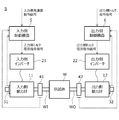
- FIG. 1 is a diagram showing a configuration of a test system S according to the present embodiment.
- the test system S evaluates the performance of the specimen W whose input and output gear ratios can be changed.
- the specimen W the input shaft WI, the output shaft WO, and the transmission mechanism that shifts the driving force input to the input shaft WI under a set gear ratio and transmits it to the output shaft WO.
- the test system S is a so-called drive train bench system that evaluates the performance of a drive train for a vehicle.
- the present invention is not limited to this. More specifically, for example, one input shaft, two output shafts, and a speed change in which the driving force input to the input shafts is changed under a set gear ratio and transmitted to the two output shafts.
- a three-axis drive train mounted on a so-called front-wheel drive (FF) vehicle equipped with a mechanism may be used as a specimen.
- the test system S includes a specimen W whose gear ratio can be changed, an input side power meter 11 coaxially connected to the input shaft WI, an output side power meter 12 coaxially connected to the output shaft WO, and an input side.
- An input side inverter 21 that supplies power to the input side power meter 11 according to the torque current command signal, an output side inverter 22 that supplies power to the output side power meter 12 according to the output side torque current command signal, and an input shaft.
- the input side angular velocity sensor 31 that detects the angular velocity of the WI
- the output side angular velocity sensor 32 that detects the angular velocity of the output shaft WO
- the input side shaft torque sensor 41 that detects the shaft torque in the input shaft WI, and the shaft in the output shaft WO.
- An output side shaft torque sensor 42 that detects torque, an input side control device 5 that generates an input side torque current command signal and inputs it to the input side inverter 21, and an output side torque current command signal that is generated and generated on the output side.
- An output side control device 6 for inputting to the inverter 22 is provided.
- the input side angular velocity sensor 31 generates an input side angular velocity detection signal corresponding to the input side angular velocity of the shaft of the input side dynamometer 11 that rotates at substantially the same speed as the input shaft WI, and inputs this to the input side control device 5.
- the output-side angular velocity sensor 32 generates an output-side angular velocity detection signal corresponding to the output-side angular velocity of the shaft of the output-side dynamometer 12 that rotates at substantially the same speed as the output-side shaft WO, and inputs this to the output-side control device 6. ..
- the input side shaft torque sensor 41 detects the input side shaft torque acting on the input shaft WI from, for example, the amount of strain in the twisting direction of the shaft, and generates an input side shaft torque detection signal corresponding to the input side shaft torque. This is input to the input side control device 5.
- the output side shaft torque sensor 42 detects the output side shaft torque acting on the output shaft WO from, for example, the amount of strain in the twisting direction of the shaft, and generates an output side shaft torque detection signal corresponding to the output side shaft torque. This is input to the output side control device 6.
- the input side control device 5 generates an input side torque current command signal based on a predetermined feedback control rule using the input side angular velocity detection signal and the input side shaft torque detection signal, and inputs the signal to the input side inverter 21. More specifically, the input side control device 5 has one or more control gains so that the deviation between the input side angular velocity command signal and the input side angular velocity detection signal in response to the command for the input side angular velocity of the input shaft WI is eliminated. It has a speed control function of generating an input side torque current command signal based on the feedback control law characterized by and inputting the signal to the input side inverter 21.
- the output side control device 6 generates an output side torque current command signal based on a predetermined feedback control rule using the output side angular velocity detection signal and the output side shaft torque detection signal, and inputs the output side torque current command signal to the output side inverter 22. More specifically, the output side control device 6 has one or more so that the deviation between the output side shaft torque command signal and the output side shaft torque detection signal corresponding to the command for the output side shaft torque of the output shaft WO is eliminated. It has a shaft torque control function that generates an output side torque current command signal based on the feedback control law characterized by the control gain of the above and inputs it to the output side inverter 22.
- the input shaft WI is speed-controlled by the input side control device 5 and the output shaft WO is controlled by the output side control device 6
- the input side control device 5 performs shaft torque control to generate an input side torque current command signal so that there is no deviation between the input side shaft torque command signal and the input side shaft torque detection signal, and the output shaft.
- the output side control device 6 may perform speed control to generate an output side torque current command signal so that the deviation between the output side angular speed command signal and the output side angular speed detection signal is eliminated.
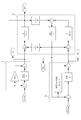
- FIG. 2 is a block diagram showing the configurations of the control circuit of the input side control device 5 and the output side control device 6 and the control target P.
- the code "s” is a Laplace operator.
- the reference numeral “J1” is the moment of inertia of the input side power meter 11
- the reference numeral “J2” is the moment of inertia of the output side power meter 12, which are known.
- the symbol “g” is a gear ratio of the specimen W.
- reference numeral “K1” is a known torsional rigidity of the output shaft WO of the specimen W.
- the code “T1” is the torque of the input side dynamometer 11, which corresponds to the input side torque current command signal generated by the input side control device 5, and the code “T2” is the torque of the output side dynamometer 12.
- the reference numeral “w1” is the angular velocity of the input shaft WI of the specimen W, and corresponds to the input side angular velocity detection signal detected by the input side angular velocity sensor 31.
- the reference numeral “Tk1” corresponds to the output side shaft torque acting on the output shaft WO of the specimen W, and corresponds to the output side shaft torque detection signal detected by the output side shaft torque sensor 42.
- the reference numeral “w1ref” is a target for the input side angular velocity detection signal w1 and corresponds to an input side angular velocity command signal input to the input side control device 5 that performs speed control.
- the reference numeral “Tk1ref” is a target for the output side shaft torque detection signal Tk1 and corresponds to an output side shaft torque command signal input to the output side control device 6 that controls the shaft torque.
- the gear ratio g of the specimen W is It can vary between the lowest gear ratio g_min and the highest gear ratio g_max. Therefore, the resonance frequency wr of the controlled object P is the lowest resonance frequency wr_min (see the following equation (1-1)) and the highest by changing the gear ratio g between the minimum gear ratio g_min and the maximum gear ratio g_max. It may vary from the resonance frequency wr_max (see equation (1-2) below).
- a three-axis drive train including two output shafts may be used as a specimen.
- the input side control device and the output side control are basically under the same two-axis transfer function model as in FIG.
- the control circuit of the device can be constructed.
- the input side control device 5 has an input side angular velocity command signal w1ref and an input side angular velocity detection signal w1 according to an IP control law characterized by two control gains (Kp1, Ki1).
- the input side torque current command signal T1 is generated so that the deviation disappears, and is input to the input side inverter 21.
- the output side control device 6 has an output side shaft torque command signal Tk1ref and an output side shaft according to the I-PD control law characterized by four control gains (Kp2, Kd2, f2, Ki2).
- the output side torque current command signal T2 is generated so as to eliminate the deviation from the torque detection signal Tk1, and is input to the output side inverter 22.
- FIG. 3 is a diagram showing the positions of the pole Ps of the speed control system closed loop transfer function and the pole Pt of the shaft torque control system closed loop transfer function described later.
- the imaginary part of the pole Ps of the speed control system closed loop transfer function as shown in the above equation (3) is substantially 0, and the pole The real part of Ps is set to be larger on the negative side than the value obtained by multiplying the resonance frequency wr by a negative sign.
- the real part of the pole Ps of the speed control system closed loop transfer function is defined as -wc1
- the real part of the pole -wc1 is larger to the negative side than the value obtained by multiplying the maximum resonance frequency wr_max by a negative sign. Is set to be.
- the control gain (Kp1, Ki1) is set so that the frequency parameter wc1 is twice the maximum resonance frequency wr_max will be described.
- the denominator polynomial of the speed control system closed loop transfer function shown in the above equation (3) (the left side of the following equation (5-1)) is the frequency parameter wc1.
- the control gain (Kp1, Ki1) is set so as to be equal to the second-order characteristic polynomial (the right side of the following equation (5-1)) obtained by using the two coefficients (c1 and c2).
- the control gain Kp1 is represented by the following formula (5-2)
- the control gain Ki1 is represented by the following formula (5-3).
- the control gain (Kp2, Kd2, f2, Ki2) of the output side control device 6 is substantially the imaginary part of the pole Pt of the shaft torque control system closed loop transfer function as shown in the above equation (7). It becomes 0, and the real part of the pole Pt is set to be negative and smaller to the negative side than the real part of the pole Ps of the speed control system closed loop transfer function. More specifically, if the real part of the pole Pt of the shaft torque control system closed loop transfer function is defined as -wc2, the real part of the pole -wc2 is negative and more negative than the value obtained by multiplying the resonance frequency wr by a negative sign.
- the denominator polynomial of the axial torque control system closed loop transfer function shown in the above equation (7) is a frequency parameter.
- Control gain (Kp2, Kd2, f2,) so as to be equal to the fourth-order characteristic polynomial (right side of equation (9-1) below) obtained by using wc2 and four coefficients (p1, p2, p3, p4).
- Ki2 The control gain Ki2 is represented by the following equation (9-5).
- test system S including the input side control device 5 and the output side control device 6 in which the control gain is set as described above will be described with reference to FIGS. 4 to 7.
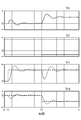
- FIGS. 4 and 5 are time charts showing a control example by the conventional test system
- FIGS. 6 and 7 are time charts showing the control example by the test system S of the present embodiment. More specifically, FIGS. 4 and 6 show a control example when the gear ratio g of the specimen W is set to the minimum gear ratio g_min
- FIGS. 5 and 7 show the maximum gear ratio g of the specimen W. An example of control when the gear ratio g_max is set is shown.
- the uppermost stage shows the time change of the input side torque current command signal T1
- the second stage from the top shows the time change of the output side torque current command signal T2
- the third stage from the top shows the input.
- the side angular velocity detection signal w1 (solid line) and the input side angular velocity command signal w1ref (broken line) are shown
- the bottom row shows the output side shaft torque detection signal Tk1 (solid line) and the output side shaft torque command signal Tk1ref (broken line).
- 4 to 7 show a case where the input side angular velocity command signal w1ref is changed in steps at time t1 and then the output side shaft torque command signal Tk1ref is changed in steps at time t2.
- the speed control response on the input shaft WI side is set lower than the minimum resonance frequency wr_min. Therefore, when the gear ratio g is set to the minimum gear ratio g_min, the input side angular velocity command is used.
- the signal w1ref and the output side shaft torque command signal Tk1ref are changed, the input side angular velocity detection signal w1 and the output side shaft torque detection signal Tk1 show an oscillating response, and the input side angular velocity detection signal w1 and the output side shaft torque detection. It takes time for the signal Tk1 to converge to each command value.
- the frequency parameter wc1 is set higher than the maximum resonance frequency wr_max (see the above equation (4)), and the speed control response of the input shaft WI is set to the conventional one. It is set to be faster than the test system. Therefore, as is clear by comparing FIGS. 6 and 7 with FIGS. 4 and 5, according to the test system S of the present embodiment, the input side angular velocity detection signal w1ref and the output side shaft torque detection signal Tk1ref are used. The vibrational response of the input side angular velocity detection signal w1 and the output side shaft torque detection signal Tk1 at the time of change can be suppressed, and can be quickly converged to each command value.
- the input side angular velocity detection signal w1 and the output side shaft are obtained even when the gear ratio g is changed.
- the time required for the torque detection signal Tk1 to converge to each command value hardly changes, that is, the control response does not change.
- the input side control device 5 controls the input side power meter 11 connected to the input shaft WI of the specimen W so that the deviation between the input side angular speed command signal w1ref and the input side angular speed detection signal w1 is eliminated.
- the output side control device 6 controls the output side power meter 12 connected to the output shaft WO of the specimen W so that the deviation between the output side shaft torque command signal Tk1ref and the output side shaft torque detection signal Tk1 is eliminated. ..
- the control gain (Kp1, Ki1) of the input side control device 5 is larger than the value obtained by multiplying the resonance frequency wr of the control target P by the negative sign of the real part of the pole Ps of the speed control system closed loop transfer function. Set so that it increases to the negative side.
- the control gains (Kp1, Ki1) of the input side control device 5 are set so that the control response of the input shaft WI that controls the speed is higher than the resonance frequency wr.
- the control gain (Kp2, Kd2, f2, Ki2) of the output side control device 6 is set so that the real part of the pole Pt of the shaft torque control system closed loop transfer function is the pole Ps of the speed control system closed loop transfer function. Set so that it is smaller on the negative side than the real part.
- the control gain (Kp2, Kd2, f2, Ki2) of the output side control device 6 is set so that the control response of the output shaft WO on the shaft torque control side is lower than the control response of the input shaft WI on the speed control side. Set.
- the output side control device 6 can perform robust torque feedback control with respect to a change in the resonance frequency wr of the controlled object P.
- the speed control of the input shaft WI and the shaft torque control of the output shaft WO can be performed without significantly changing the control response. It can be carried out.
- the control gain (Kp2, Kd2, f2, Ki2) of the output side control device 6 is set to the resonance frequency wr of the control target P by the real part of the pole Pt of the shaft torque control system closed loop transfer function. Set so that it becomes smaller on the negative side than the value multiplied by the negative sign.
- the robustness of the shaft torque control by the output side control device 6 can be further improved, so that the change in the control response due to the change in the resonance frequency wr of the controlled object P can be further suppressed.
- the control gain (Kp1, Ki1) of the input side control device 5 is larger than the value obtained by multiplying the maximum resonance frequency wr_max by a negative sign in the real part of the pole Ps of the speed control system closed loop transfer function. Set so that it increases to the negative side. As a result, the apparent inertia of the input shaft WI on the speed control side as seen from the output shaft WO on the shaft torque control side can be further increased. Further, in the test system S, the control gain (Kp2, Kd2, f2, Ki2) of the output side control device 6 is multiplied by a negative sign on the minimum resonance frequency wr_min by the real part of the pole Pt of the shaft torque control system closed loop transfer function.
- the input side angular speed command signal w1ref and the output side shaft torque command signal Tk1ref are changed, the input side angular speed detection signal w1 and the output The side shaft torque detection signal Tk1 may exhibit vibrational behavior.
- the control gains (Kp1, Ki1) of the input side control device 5 are set so that the imaginary part of the pole of the speed control system closed loop transfer function becomes 0, and the control of the output side control device 6 is controlled.
- the gain (Kp2, Kd2, f2, Ki2) is set so that the imaginary part of the pole Pt of the shaft torque control system closed loop transfer function becomes 0.
- the input shaft WI is speed controlled by the input side control device 5 and the output shaft WO is controlled by the output side control device 6 has been described, but the present invention is not limited to this. ..
- the input shaft WI may be controlled by the input side control device
- the output shaft WO may be controlled by the output side control device.
- the control gain of the output side control device that performs speed control is such that the real part of the pole of the speed control system closed loop transfer function from the speed command signal to the speed detection signal is the resonance frequency wr (more preferably the highest) of the control target P. It is preferable to set the resonance frequency wr_max) to be larger on the negative side than the value obtained by multiplying the negative number.
- the control gain of the input side control device that controls the shaft torque is such that the real part of the pole of the shaft torque control system closed loop transfer function from the shaft torque command signal to the shaft torque detection signal is the real part of the pole of the speed control system closed loop transfer function. It is preferable to set it so that it becomes smaller on the negative side than. More preferably, the control gain of the input side control device is the value obtained by multiplying the resonance frequency wr (more preferably the lowest resonance frequency wr_min) to be controlled by the negative sign of the real part of the pole of the shaft torque control system closed loop transfer function. It is preferable to set it so that it becomes smaller on the negative side.
- control gain of the input side control device is 0 at the imaginary part of the pole of the speed control system closed loop transfer function
- the control gain of the output side control device is the imaginary part of the pole of the shaft torque control system closed loop transfer function. Is preferably set to 0.
- Output side shaft torque detection signal (torque detection signal) Tk1ref ... Output side shaft torque command signal (torque command signal) Kp1, Ki1 ... Control gain (control gain of speed control device) Kp2, Kd2, f2, Ki2 ... Control gain (control gain of torque control device) wr ... Resonance frequency wr_min ... Minimum resonance frequency (minimum frequency) wr_max ... Maximum resonance frequency (maximum frequency)
Landscapes
- Physics & Mathematics (AREA)
- General Physics & Mathematics (AREA)
- Testing Of Devices, Machine Parts, Or Other Structures Thereof (AREA)
Abstract
試験システムは、変速比gを変更可能な供試体に連結された入力側及び出力側動力計と、速度指令信号w1refと速度検出信号w1との偏差が無くなるように入力側動力計を制御する入力側制御装置5と、トルク指令信号Tk1refとトルク検出信号Tk1との偏差が無くなるように出力側動力計を制御する出力側制御装置6と、を備える。入力側制御装置5の制御ゲインは、速度制御系閉ループ伝達関数(w1/w1ref)の極の実部が、共振周波数に負号を乗じた値よりも負側へ大きくなるように設定され、出力側制御装置6の制御ゲインは、軸トルク制御系閉ループ伝達関数(Tk1/Tk1ref)の極の実部が速度制御系閉ループ伝達関数の極の実部よりも負側へ小さくなるように設定されている。
Description
本発明は、試験システムに関する。より詳しくは、例えば車両のドライブトレインのように共振周波数が変化し得る供試体の入力軸及び出力軸それぞれに連結された動力計を備える試験システムに関する。
ドライブトレインとは、エンジンで発生したエネルギーを駆動輪に伝達するための複数の装置の総称をいい、エンジン、クラッチ、トランスミッション、ドライブシャフト、プロペラシャフト、デファレンシャルギヤ、及び駆動輪等で構成される。ドライブトレインの試験システムでは、実際にエンジンでトランスミッションを駆動するとともに、その出力軸に接続された出力側動力計を電気慣性制御することにより、タイヤや車体の慣性を模した負荷トルクを出力軸に付与しながら、ドライブトレインの耐久性能や品質等が評価される(例えば、特許文献1参照)。また近年では、ドライブトレインの入力軸に入力する駆動トルクを、実エンジンの代わりに入力側動力計で発生させる試験システムも提案されている(例えば、特許文献2参照)。
ここで例えば、供試体であるドライブトレインの入力軸及び出力軸それぞれに動力計を連結し、これら動力計を用いることによって入力軸及び出力軸をそれぞれ速度制御及びトルク制御する場合を検討する。ドライブトレインの試験システムは、入力軸と出力軸との間に設置される供試体の変速比が変化することによって、共振周波数も最低周波数と最高周波数との間で変化する。このような共振周波数の変化に対応するため、従来の技術では、入力軸側に対しては最低周波数よりも低い制御応答の下で速度制御を行い、出力軸側に対しては軸トルクをフィードバックしないトルク制御を行っていた。しかしながらこの場合、後に図4及び図5を参照して説明するように変速比の変化に伴って制御応答も変化する。
本発明は、供試体の入力軸及び出力軸の何れか一方を速度制御し何れか他方をトルク制御する試験システムにおいて、供試体の変速比が変化しても大きく制御応答を変化させることなく速度制御及びトルク制御を行うことができる試験システムを提供することを目的とする。
(1)本発明に係る試験システム(例えば、後述の試験システム)は、入力と出力との変速比(例えば、後述の変速比g)を変更可能な供試体(例えば、後述の供試体W)の入力軸(例えば、後述の入力軸WI)及び出力軸(例えば、後述の出力軸WO)それぞれに連結された動力計(例えば、後述の入力側動力計11及び出力側動力計12)と、前記入力軸及び前記出力軸の何れか一方の軸(例えば、後述の入力軸WI)の速度に応じた速度検出信号(例えば、後述の入力側角速度検出信号w1)を生成する速度検出器(例えば、後述の入力側角速度センサ31)と、前記入力軸及び前記出力軸の何れか他方の軸(例えば、後述の出力軸WO)のトルクに応じたトルク検出信号(例えば、後述の出力側軸トルク検出信号Tk1)を生成するトルク検出器(例えば、後述の出力側軸トルクセンサ42)と、前記速度に対する指令に応じた速度指令信号(例えば、後述の入力側角速度指令信号w1ref)と前記速度検出信号との偏差が無くなるように前記一方の軸に連結された動力計(例えば、後述の入力側動力計11)を制御する速度制御装置(例えば、後述の入力側制御装置5)と、前記トルクに対する指令に応じたトルク指令信号(例えば、後述の出力側軸トルク指令信号Tk1ref)と前記トルク検出信号との偏差が無くなるように前記他方の軸に連結された動力計(例えば、後述の出力側動力計12)を制御するトルク制御装置(例えば、後述の出力側制御装置6)と、を備える。前記速度制御装置の制御ゲイン(例えば、後述の制御ゲイン(Kp1,Ki1))は、前記速度指令信号から前記速度検出信号までの速度制御系閉ループ伝達関数の極(例えば、後述の極Ps)の実部が、前記供試体を含む制御対象の共振周波数(例えば、後述の共振周波数wr)に負号を乗じた値よりも負側へ大きくなるように設定され、前記トルク制御装置の制御ゲイン(例えば、後述の制御ゲイン(Kp2,Kd2,f2,Ki2))は、前記トルク指令信号から前記トルク検出信号までのトルク制御系閉ループ伝達関数の極(例えば、後述の極Pt)の実部が前記速度制御系閉ループ伝達関数の極の実部よりも負側へ小さくなるように設定されていることを特徴とする。
(2)この場合、前記トルク制御装置の制御ゲインは、前記トルク制御系閉ループ伝達関数の極の実部が、前記制御対象の共振周波数に負号を乗じた値よりも負側へ小さくなるように設定されていることが好ましい。
(3)この場合、前記制御対象の共振周波数は、前記変速比が変化することによって最低周波数(例えば、後述の最低共振周波数wr_min)と最高周波数(例えば、後述の最高共振周波数wr_max)との間で変化し、前記速度制御装置の制御ゲインは、前記速度制御系閉ループ伝達関数の極の実部が、前記最高周波数に負号を乗じた値よりも負側へ大きくなるように設定され、前記トルク制御装置の制御ゲインは、前記トルク制御系閉ループ伝達関数の極の実部が、前記最低周波数に負号を乗じた値よりも負側へ小さくなるように設定されていることが好ましい。
(4)この場合、前記速度制御装置の制御ゲインは、前記速度制御系閉ループ伝達関数の極の虚部が0となるように設定され、前記トルク制御装置の制御ゲインは、前記トルク制御系閉ループ伝達関数の極の虚部が0となるように設定されていることが好ましい。
(1)本発明に係る試験システムにおいて、速度制御装置は、速度指令信号と速度検出信号との偏差が無くなるように、供試体の入力軸及び出力軸の何れか一方の軸(以下では、「速度制御側の軸」ともいう)に連結された動力計を制御し、トルク制御装置は、トルク指令信号とトルク検出信号との偏差が無くなるように、何れか他方の軸(以下では、「トルク制御側の軸」ともいう)に連結された動力計を制御する。また本発明では、速度制御装置の制御ゲインを、速度制御系閉ループ伝達関数の極の実部が、供試体及びその入出力軸に連結された動力計等を含む制御対象の共振周波数に負号を乗じた値よりも負側へ大きくなるように設定する。換言すれば、速度制御側の軸の制御応答が共振周波数よりも高くなるように速度制御装置の制御ゲインを設定する。これにより、トルク制御側の軸からみた速度制御側の軸のみかけの慣性を大きくすることができる。また本発明では、トルク制御装置の制御ゲインを、トルク制御系閉ループ伝達関数の極の実部が、速度制御系閉ループ伝達関数の極の実部よりも負側へ小さくなるように設定する。換言すれば、トルク制御側の軸の制御応答が速度制御側の軸の制御応答よりも低くなるようにトルク制御装置の制御ゲインを設定する。これによりトルク制御装置では、制御対象の共振周波数の変化に対してロバストなトルクフィードバック制御を行うことができる。これにより、供試体の変速比の変化に伴って共振周波数が変化した場合であっても、大きく制御応答を変化させることなく入出力軸の速度制御及びトルク制御を行うことができる。
(2)本発明に係る試験システムでは、トルク制御装置の制御ゲインを、トルク制御系閉ループ伝達関数の極の実部が、制御対象の共振周波数に負号を乗じた値よりも負側へ小さくなるように設定する。これによりトルク制御装置によるトルク制御のロバスト性をさらに向上できるので、制御対象の共振周波数の変化に伴う制御応答の変化をさらに抑制できる。
(3)本発明に係る試験システムでは、速度制御装置の制御ゲインを、速度制御系閉ループ伝達関数の極の実部が、共振周波数の最高周波数に負号を乗じた値よりも負側へ大きくなるように設定する。これにより、トルク制御側の軸からみた速度制御側の軸のみかけの慣性をさらに大きくできる。また本発明では、トルク制御装置の制御ゲインを、トルク制御系閉ループ伝達関数の極の実部が、共振周波数の最低周波数に負号を乗じた値よりも負側へ小さくなるように設定する。これによりトルク制御装置によるトルク制御のロバスト性をさらに向上できるので、制御対象の共振周波数の変化に伴う制御応答の変化をさらに抑制できる。
(4)後に図4及び図5を参照して説明するように、従来の技術では、速度指令信号やトルク指令信号を変化させると、速度検出信号やトルク検出信号が振動的な挙動を示す場合がある。これに対し本発明に係る試験システムでは、速度制御装置の制御ゲインを、速度制御系閉ループ伝達関数の極の虚部が0となるように設定し、トルク制御装置の制御ゲインを、トルク制御系閉ループ伝達関数の極の虚部が0となるように設定する。これにより、速度検出信号やトルク検出信号の振動的な挙動を抑制することができる。
以下、本発明の一実施形態について、図面を参照しながら詳細に説明する。
図1は、本実施形態に係る試験システムSの構成を示す図である。試験システムSは、入力と出力の変速比を変更可能な供試体Wの性能を評価するものである。以下では、供試体Wとして、入力軸WIと、出力軸WOと、入力軸WIに入力される駆動力を設定された変速比の下で変速して出力軸WOに伝達する変速機構と、を備える車両用のドライブトレインとした場合について説明する。すなわち試験システムSは、車両用のドライブトレインの性能を評価する所謂ドライブトレインベンチシステムと呼称されるものである。また以下では、所謂後輪駆動(FR)車両に搭載される2軸のドライブトレインを供試体Wとした場合について説明するが、本発明はこれに限らない。より具体的には、例えば1本の入力軸と、2本の出力軸と、入力軸に入力される駆動力を設定された変速比の下で変速して2本の出力軸に伝達する変速機構と、を備える所謂前輪駆動(FF)車両に搭載される3軸のドライブトレインを供試体としてもよい。
図1は、本実施形態に係る試験システムSの構成を示す図である。試験システムSは、入力と出力の変速比を変更可能な供試体Wの性能を評価するものである。以下では、供試体Wとして、入力軸WIと、出力軸WOと、入力軸WIに入力される駆動力を設定された変速比の下で変速して出力軸WOに伝達する変速機構と、を備える車両用のドライブトレインとした場合について説明する。すなわち試験システムSは、車両用のドライブトレインの性能を評価する所謂ドライブトレインベンチシステムと呼称されるものである。また以下では、所謂後輪駆動(FR)車両に搭載される2軸のドライブトレインを供試体Wとした場合について説明するが、本発明はこれに限らない。より具体的には、例えば1本の入力軸と、2本の出力軸と、入力軸に入力される駆動力を設定された変速比の下で変速して2本の出力軸に伝達する変速機構と、を備える所謂前輪駆動(FF)車両に搭載される3軸のドライブトレインを供試体としてもよい。
試験システムSは、変速比を変更可能な供試体Wと、入力軸WIと同軸に連結された入力側動力計11と、出力軸WOと同軸に連結された出力側動力計12と、入力側トルク電流指令信号に応じて入力側動力計11に電力を供給する入力側インバータ21と、出力側トルク電流指令信号に応じて出力側動力計12に電力を供給する出力側インバータ22と、入力軸WIの角速度を検出する入力側角速度センサ31と、出力軸WOの角速度を検出する出力側角速度センサ32と、入力軸WIにおける軸トルクを検出する入力側軸トルクセンサ41と、出力軸WOにおける軸トルクを検出する出力側軸トルクセンサ42と、入力側トルク電流指令信号を生成しこれを入力側インバータ21へ入力する入力側制御装置5と、出力側トルク電流指令信号を生成しこれを出力側インバータ22へ入力する出力側制御装置6と、を備える。
入力側角速度センサ31は、入力軸WIとほぼ同じ速度で回転する入力側動力計11の軸の入力側角速度に応じた入力側角速度検出信号を発生し、これを入力側制御装置5へ入力する。出力側角速度センサ32は、出力軸WOとほぼ同じ速度で回転する出力側動力計12の軸の出力側角速度に応じた出力側角速度検出信号を発生し、これを出力側制御装置6へ入力する。
入力側軸トルクセンサ41は、入力軸WIに作用する入力側軸トルクを、例えば軸のねじれ方向の歪み量から検出し、この入力側軸トルクに応じた入力側軸トルク検出信号を発生し、これを入力側制御装置5へ入力する。出力側軸トルクセンサ42は、出力軸WOに作用する出力側軸トルクを、例えば軸のねじれ方向の歪み量から検出し、この出力側軸トルクに応じた出力側軸トルク検出信号を発生し、これを出力側制御装置6へ入力する。
入力側制御装置5は、入力側角速度検出信号及び入力側軸トルク検出信号を用いた所定のフィードバック制御則に基づいて入力側トルク電流指令信号を生成し、入力側インバータ21へ入力する。より具体的には、入力側制御装置5は、入力軸WIの入力側角速度に対する指令に応じた入力側角速度指令信号と入力側角速度検出信号との偏差が無くなるように、1つ以上の制御ゲインによって特徴付けられるフィードバック制御則に基づいて入力側トルク電流指令信号を生成し、これを入力側インバータ21へ入力する速度制御機能を備える。
出力側制御装置6は、出力側角速度検出信号及び出力側軸トルク検出信号を用いた所定のフィードバック制御則に基づいて出力側トルク電流指令信号を生成し、出力側インバータ22へ入力する。より具体的には、出力側制御装置6は、出力軸WOの出力側軸トルクに対する指令に応じた出力側軸トルク指令信号と出力側軸トルク検出信号との偏差が無くなるように、1つ以上の制御ゲインによって特徴付けられるフィードバック制御則に基づいて出力側トルク電流指令信号を生成し、これを出力側インバータ22へ入力する軸トルク制御機能を備える。
以上のように本実施形態では、入力軸WIについては入力側制御装置5によって速度制御を行い、出力軸WOについては出力側制御装置6によって軸トルク制御を行う場合について説明するが、本発明はこれに限らない。例えば、入力軸WIについては入力側制御装置5によって入力側軸トルク指令信号と入力側軸トルク検出信号との偏差が無くなるように入力側トルク電流指令信号を生成する軸トルク制御を行い、出力軸WOについては出力側制御装置6によって出力側角速度指令信号と出力側角速度検出信号との偏差が無くなるように出力側トルク電流指令信号を生成する速度制御を行ってもよい。
図2は、入力側制御装置5及び出力側制御装置6の制御回路及び制御対象Pの構成を示すブロック図である。
図2において、符号“s”はラプラス演算子である。また符号“J1”は入力側動力計11の慣性モーメントであり、符号“J2”は出力側動力計12の慣性モーメントであり、それぞれ既知である。また符号“g”は、供試体Wの変速比である。また符号“K1”は、供試体Wの出力軸WOのねじり剛性であり、既知である。また符号“T1”は、入力側動力計11のトルクであり、入力側制御装置5によって生成される入力側トルク電流指令信号に相当し、符号“T2”は、出力側動力計12のトルクであり、出力側制御装置6によって生成される出力側トルク電流指令信号に相当する。また符号“w1”は、供試体Wの入力軸WIの角速度であり、入力側角速度センサ31によって検出される入力側角速度検出信号に相当する。また符号“Tk1”は、供試体Wの出力軸WOに作用する出力側軸トルクに相当し、出力側軸トルクセンサ42によって検出される出力側軸トルク検出信号に相当する。また符号“w1ref”は、入力側角速度検出信号w1に対する目標であり、速度制御を行う入力側制御装置5に入力する入力側角速度指令信号に相当する。また符号“Tk1ref”は、出力側軸トルク検出信号Tk1に対する目標であり、軸トルク制御を行う出力側制御装置6に入力する出力側軸トルク指令信号に相当する。
上述のように供試体W、入力軸WIに連結された入力側動力計11、及び出力軸WOに連結された出力側動力計12等を含む制御対象Pにおいて、供試体Wの変速比gは最低変速比g_minと最高変速比g_maxとの間で変化し得る。このため、制御対象Pの共振周波数wrは、変速比gを最低変速比g_minと最高変速比g_maxとの間で変化することによって、最低共振周波数wr_min(下記式(1-1)参照)と最高共振周波数wr_max(下記式(1-2)参照)との間で変わり得る。

ところで上述のように本発明は、2本の出力軸を備える3軸のドライブトレインを供試体としてもよい。この場合、2本の出力軸の慣性モーメント、トルク、及びねじりトルクを合計値として扱うことにより、基本的には図2と同じ2軸の伝達関数モデルの下で入力側制御装置及び出力側制御装置の制御回路を構築できる。
入力側制御装置5は、例えば図2に示すように、2つの制御ゲイン(Kp1,Ki1)によって特徴付けられるI-P制御則により、入力側角速度指令信号w1refと入力側角速度検出信号w1との偏差が無くなるように入力側トルク電流指令信号T1を生成し、入力側インバータ21へ入力する。
出力側制御装置6は、例えば図2に示すように、4つの制御ゲイン(Kp2,Kd2,f2,Ki2)によって特徴付けられるI-PD制御則により、出力側軸トルク指令信号Tk1refと出力側軸トルク検出信号Tk1との偏差が無くなるように出力側トルク電流指令信号T2を生成し、出力側インバータ22へ入力する。
次に入力側制御装置5の制御ゲイン(Kp1,Ki1)の設定について説明する。
先ず、制御対象Pを慣性モーメントJ1の慣性体とみなすと、その運動方程式は下記式(2)によって近似的に表される。

先ず、制御対象Pを慣性モーメントJ1の慣性体とみなすと、その運動方程式は下記式(2)によって近似的に表される。
また制御対象Pの運動方程式を上記式(2)によって近似すると、入力側角速度指令信号w1refから入力側角速度検出信号w1までの速度制御系閉ループ伝達関数は、下記式(3)によって表される。

図3は、速度制御系閉ループ伝達関数の極Ps及び後述の軸トルク制御系閉ループ伝達関数の極Ptの位置を示す図である。図3に示すように、入力側制御装置5の制御ゲイン(Kp1,Ki1)は、上記式(3)に示すような速度制御系閉ループ伝達関数の極Psの虚部が略0となり、かつ極Psの実部が共振周波数wrに負号を乗じた値よりも負側へ大きくなるように設定される。より具体的には、速度制御系閉ループ伝達関数の極Psの実部を-wc1と定義すると、極の実部-wc1は、最高共振周波数wr_maxに負号を乗じた値よりも負側へ大きくなるように設定される。なお以下では、下記式(4)に示すように、周波数パラメータwc1が最高共振周波数wr_maxの2倍となるように、制御ゲイン(Kp1,Ki1)を設定した場合について説明する。

より具体的には、下記式(5-1)に示すように、上記式(3)に示す速度制御系閉ループ伝達関数の分母多項式(下記式(5-1)の左辺)が、周波数パラメータwc1と2つの係数(c1,c2)とを用いて得られる2次の特性多項式(下記式(5-1)の右辺)と等しくなるように制御ゲイン(Kp1,Ki1)を設定する。これにより、制御ゲインKp1は、下記式(5-2)によって表され、制御ゲインKi1は、下記式(5-3)によって表される。

なお上記式(5-2)及び(5-3)において、係数(c1,c2)は、例えば、上記式(3)に示す速度制御系閉ループ伝達関数の極の虚部が0となりかつ実部が-wc1となるような値に設定される。より具体的には、c1=2、c2=1である。
次に出力側制御装置6の制御ゲイン(Kp2,Kd2,f2,Ki2)の設定について説明する。
先ず、供試体Wの変速比gを0以外の値、例えば1とし、さらに慣性モーメントJ1を無限大とすると、制御対象Pにおける出力側動力計12のトルクT2に対する出力側軸トルク検出信号Tk1の伝達関数は、下記式(6)によって表される。

先ず、供試体Wの変速比gを0以外の値、例えば1とし、さらに慣性モーメントJ1を無限大とすると、制御対象Pにおける出力側動力計12のトルクT2に対する出力側軸トルク検出信号Tk1の伝達関数は、下記式(6)によって表される。
また上記式(6)に示す伝達関数と出力側制御装置6の制御回路とを組み合わせると、出力側軸トルク指令信号Tk1refから出力側軸トルク検出信号Tk1までの軸トルク制御系閉ループ伝達関数は、下記式(7)によって表される。

図3に示すように、出力側制御装置6の制御ゲイン(Kp2,Kd2,f2,Ki2)は、上記式(7)に示すような軸トルク制御系閉ループ伝達関数の極Ptの虚部が略0となり、極Ptの実部が負値かつ速度制御系閉ループ伝達関数の極Psの実部よりも負側へ小さくなるように設定される。より具体的には、軸トルク制御系閉ループ伝達関数の極Ptの実部を-wc2と定義すると、極の実部-wc2は、負値かつ共振周波数wrに負号を乗じた値よりも負側へ小さくなるように、より好ましくは負値かつ最低共振周波数wr_minに負号を乗じた値よりも負側へ小さくなるように設定される。なお以下では、下記式(8)に示すように、周波数パラメータwc2が最低共振周波数wr_minの1/2倍となるように、制御ゲイン(Kp2,Kd2,f2,Ki2)を設定した場合について説明する。

より具体的には、下記式(9-1)に示すように、上記式(7)に示す軸トルク制御系閉ループ伝達関数の分母多項式(下記式(9-1)の左辺)が、周波数パラメータwc2と4つの係数(p1,p2,p3,p4)とを用いて得られる4次の特性多項式(下記式(9-1)の右辺)と等しくなるように制御ゲイン(Kp2,Kd2,f2,Ki2)を設定する。これにより、制御ゲインKp2は、下記式(9-2)によって表され、制御ゲインKd2は、下記式(9-3)によって表され、制御ゲインf2は、下記式(9-4)によって表され、制御ゲインKi2は、下記式(9-5)によって表される。
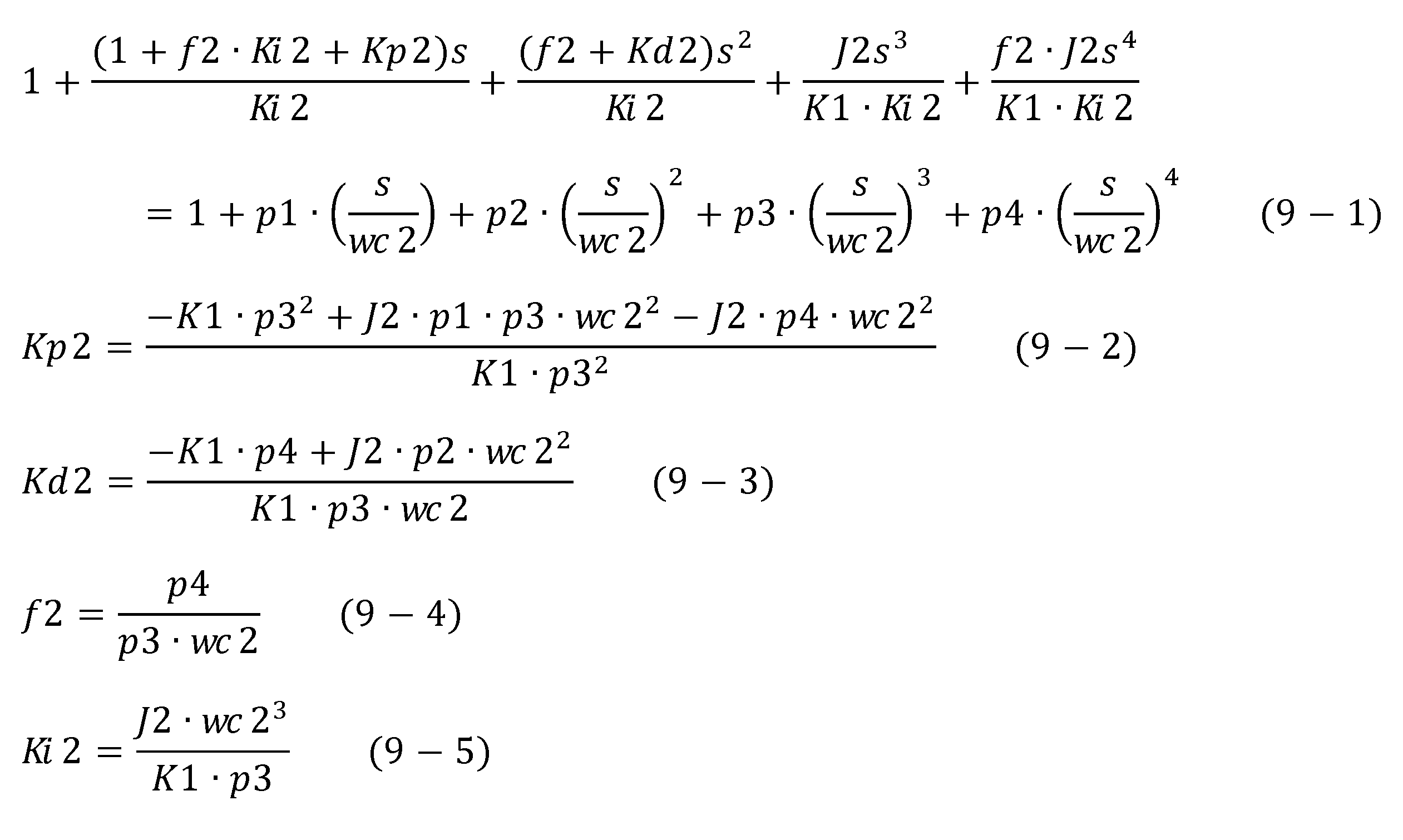
なお上記式(9-2)~(9-5)において、係数(p1,p2,p3,p4)は、例えば、上記式(7)に示す軸トルク制御系閉ループ伝達関数の極の虚部が0となりかつ実部が-wc2となるような値に設定される。より具体的には、p1=4、p2=6、p3=4、p4=1である。
次に、上述のようにして制御ゲインが設定された入力側制御装置5及び出力側制御装置6を備える試験システムSの効果について、図4~図7を参照しながら説明する。
図4及び図5は、従来の試験システムによる制御例を示すタイムチャートであり、図6及び図7は、本実施形態の試験システムSによる制御例を示すタイムチャートである。より具体的には、図4及び図6は、供試体Wの変速比gを最低変速比g_minとした場合の制御例を示し、図5及び図7は、供試体Wの変速比gを最高変速比g_maxとした場合の制御例を示す。
ここで従来の試験システムとは、入力軸WIに対しては最低共振周波数wr_minより低い制御応答(すなわち、上記周波数パラメータwc1)の下で速度制御を行い、出力軸WOに対しては出力側軸トルク検出信号Tk1をフィードバックせずに軸トルク制御を行うもの、すなわち出力側軸トルク指令信号Tk1ref=出力側トルク電流指令信号T2とするものをいう。
また図4~図7において、最上段は入力側トルク電流指令信号T1の時間変化を示し、上から2段目は出力側トルク電流指令信号T2の時間変化を示し、上から3段目は入力側角速度検出信号w1(実線)及び入力側角速度指令信号w1ref(破線)を示し、最下段は出力側軸トルク検出信号Tk1(実線)及び出力側軸トルク指令信号Tk1ref(破線)を示す。また図4~図7では、時刻t1において入力側角速度指令信号w1refをステップ状に変化させ、その後時刻t2において出力側軸トルク指令信号Tk1refをステップ状に変化させた場合を示す。
図4に示すように、従来の試験システムでは、入力軸WI側の速度制御応答を最低共振周波数wr_minより低く設定しているため、変速比gを最低変速比g_minとした場合、入力側角速度指令信号w1refや出力側軸トルク指令信号Tk1refを変化させると、入力側角速度検出信号w1及び出力側軸トルク検出信号Tk1は振動的な応答を示し、また入力側角速度検出信号w1及び出力側軸トルク検出信号Tk1が各々の指令値に収束するまでに時間がかかる。
図5に示すように、変速比gを最高変速比g_maxとした場合、入力側角速度指令信号w1refや出力側軸トルク指令信号Tk1refが変化すると、入力側角速度検出信号w1及び出力側軸トルク検出信号Tk1は振動的な応答を示す。また図4と図5を比較すると明らかなように、変速比gを変化させると、入力側角速度検出信号w1及び出力側軸トルク検出信号Tk1が各々の指令値に収束するまでにかかる時間、すなわち制御応答が変化する。
図6及び図7に示すように、本実施形態の試験システムSでは、周波数パラメータwc1を最高共振周波数wr_maxより高く設定し(上記式(4)参照)、入力軸WIの速度制御応答を従来の試験システムよりも早くなるように設定している。このため、図6及び図7と図4及び図5とを比較して明らかなように、本実施形態の試験システムSによれば、入力側角速度検出信号w1ref及び出力側軸トルク検出信号Tk1refを変化させときにおける入力側角速度検出信号w1及び出力側軸トルク検出信号Tk1の振動的な応答を抑制でき、かつ速やかに各々の指令値に収束させることができる。
また図6と図7とを比較して明らかなように、本実施形態の試験システムSによれば、変速比gを変化させた場合であっても、入力側角速度検出信号w1及び出力側軸トルク検出信号Tk1が各々の指令値に収束するまでにかかる時間はほとんど変化せず、すなわち制御応答が変化することもない。
本実施形態の試験システムSによれば、以下の効果を奏する。
(1)入力側制御装置5は、入力側角速度指令信号w1refと入力側角速度検出信号w1との偏差が無くなるように、供試体Wの入力軸WIに連結された入力側動力計11を制御し、出力側制御装置6は、出力側軸トルク指令信号Tk1refと出力側軸トルク検出信号Tk1との偏差が無くなるように、供試体Wの出力軸WOに連結された出力側動力計12を制御する。また試験システムSでは、入力側制御装置5の制御ゲイン(Kp1,Ki1)を、速度制御系閉ループ伝達関数の極Psの実部が制御対象Pの共振周波数wrに負号を乗じた値よりも負側へ大きくなるように設定する。換言すれば、速度制御を行う入力軸WIの制御応答が共振周波数wrよりも高くなるように入力側制御装置5の制御ゲイン(Kp1,Ki1)を設定する。これにより、軸トルク制御を行う出力軸WOからみた入力軸WIのみかけの慣性を大きくすることができる。また試験システムSでは、出力側制御装置6の制御ゲイン(Kp2,Kd2,f2,Ki2)を、軸トルク制御系閉ループ伝達関数の極Ptの実部が、速度制御系閉ループ伝達関数の極Psの実部よりも負側へ小さくなるように設定する。換言すれば、軸トルク制御側の出力軸WOの制御応答が速度制御側の入力軸WIの制御応答よりも低くなるように出力側制御装置6の制御ゲイン(Kp2,Kd2,f2,Ki2)を設定する。これにより出力側制御装置6では、制御対象Pの共振周波数wrの変化に対してロバストなトルクフィードバック制御を行うことができる。これにより、供試体Wの変速比gの変化に伴って共振周波数wrが変化した場合であっても、大きく制御応答を変化させることなく入力軸WIの速度制御及び出力軸WOの軸トルク制御を行うことができる。
(1)入力側制御装置5は、入力側角速度指令信号w1refと入力側角速度検出信号w1との偏差が無くなるように、供試体Wの入力軸WIに連結された入力側動力計11を制御し、出力側制御装置6は、出力側軸トルク指令信号Tk1refと出力側軸トルク検出信号Tk1との偏差が無くなるように、供試体Wの出力軸WOに連結された出力側動力計12を制御する。また試験システムSでは、入力側制御装置5の制御ゲイン(Kp1,Ki1)を、速度制御系閉ループ伝達関数の極Psの実部が制御対象Pの共振周波数wrに負号を乗じた値よりも負側へ大きくなるように設定する。換言すれば、速度制御を行う入力軸WIの制御応答が共振周波数wrよりも高くなるように入力側制御装置5の制御ゲイン(Kp1,Ki1)を設定する。これにより、軸トルク制御を行う出力軸WOからみた入力軸WIのみかけの慣性を大きくすることができる。また試験システムSでは、出力側制御装置6の制御ゲイン(Kp2,Kd2,f2,Ki2)を、軸トルク制御系閉ループ伝達関数の極Ptの実部が、速度制御系閉ループ伝達関数の極Psの実部よりも負側へ小さくなるように設定する。換言すれば、軸トルク制御側の出力軸WOの制御応答が速度制御側の入力軸WIの制御応答よりも低くなるように出力側制御装置6の制御ゲイン(Kp2,Kd2,f2,Ki2)を設定する。これにより出力側制御装置6では、制御対象Pの共振周波数wrの変化に対してロバストなトルクフィードバック制御を行うことができる。これにより、供試体Wの変速比gの変化に伴って共振周波数wrが変化した場合であっても、大きく制御応答を変化させることなく入力軸WIの速度制御及び出力軸WOの軸トルク制御を行うことができる。
(2)試験システムSでは、出力側制御装置6の制御ゲイン(Kp2,Kd2,f2,Ki2)を、軸トルク制御系閉ループ伝達関数の極Ptの実部が、制御対象Pの共振周波数wrに負号を乗じた値よりも負側へ小さくなるように設定する。これにより出力側制御装置6による軸トルク制御のロバスト性をさらに向上できるので、制御対象Pの共振周波数wrの変化に伴う制御応答の変化をさらに抑制できる。
(3)試験システムSでは、入力側制御装置5の制御ゲイン(Kp1,Ki1)を、速度制御系閉ループ伝達関数の極Psの実部が、最高共振周波数wr_maxに負号を乗じた値よりも負側へ大きくなるように設定する。これにより、軸トルク制御側の出力軸WOからみた速度制御側の入力軸WIのみかけの慣性をさらに大きくできる。また試験システムSでは、出力側制御装置6の制御ゲイン(Kp2,Kd2,f2,Ki2)を、軸トルク制御系閉ループ伝達関数の極Ptの実部が、最低共振周波数wr_minに負号を乗じた値よりも負側へ小さくなるように設定する。これにより出力側制御装置6による軸トルク制御のロバスト性をさらに向上できるので、制御対象Pの共振周波数wrの変化に伴う制御応答の変化をさらに抑制できる。
(4)図4及び図5を参照して説明したように、従来の試験システムでは、入力側角速度指令信号w1refや出力側軸トルク指令信号Tk1refを変化させると、入力側角速度検出信号w1や出力側軸トルク検出信号Tk1が振動的な挙動を示す場合がある。これに対し試験システムSでは、入力側制御装置5の制御ゲイン(Kp1,Ki1)を、速度制御系閉ループ伝達関数の極の虚部が0となるように設定し、出力側制御装置6の制御ゲイン(Kp2,Kd2,f2,Ki2)を、軸トルク制御系閉ループ伝達関数の極Ptの虚部が0となるように設定する。これにより、入力側角速度検出信号w1や出力側軸トルク検出信号Tk1の振動的な挙動を抑制することができる。
以上、本発明の一実施形態について説明したが、本発明はこれに限らない。本発明の趣旨の範囲内で、細部の構成を適宜変更してもよい。
上記実施形態では、入力軸WIについては入力側制御装置5によって速度制御を行い、出力軸WOについては出力側制御装置6によって軸トルク制御を行う場合について説明したが、本発明はこれに限らない。上述のように入力軸WIについては入力側制御装置によって軸トルク制御を行い、出力軸WOについては出力側制御装置によって速度制御を行ってもよい。この場合、速度制御を行う出力側制御装置の制御ゲインは、速度指令信号から速度検出信号までの速度制御系閉ループ伝達関数の極の実部が、制御対象Pの共振周波数wr(より好ましくは最高共振周波数wr_max)に負号を乗じた値よりも負側へ大きくなるように設定することが好ましい。また軸トルク制御を行う入力側制御装置の制御ゲインは、軸トルク指令信号から軸トルク検出信号までの軸トルク制御系閉ループ伝達関数の極の実部が速度制御系閉ループ伝達関数の極の実部よりも負側へ小さくなるように設定することが好ましい。より好ましくは、入力側制御装置の制御ゲインは、軸トルク制御系閉ループ伝達関数の極の実部が、制御対象の共振周波数wr(より好ましくは最低共振周波数wr_min)に負号を乗じた値よりも負側へ小さくなるように設定することが好ましい。またこの場合、入力側制御装置の制御ゲインは、速度制御系閉ループ伝達関数の極の虚部が0となり、かつ出力側制御装置の制御ゲインは、軸トルク制御系閉ループ伝達関数の極の虚部が0となるように設定することが好ましい。
S…試験システム
W…供試体
WI…入力軸
WO…出力軸
11…入力側動力計(動力計)
12…出力側動力計(動力計)
31…入力側角速度センサ(速度検出器)
32…出力側角速度センサ(速度検出器)
41…入力側軸トルクセンサ(軸トルク検出器)
42…出力側軸トルクセンサ(軸トルク検出器)
5…入力側制御装置(速度制御装置)
6…出力側制御装置(トルク制御装置)
w1…入力側角速度検出信号(速度検出信号)
w1ref…入力側角速度指令信号(速度指令信号)
Tk1…出力側軸トルク検出信号(トルク検出信号)
Tk1ref…出力側軸トルク指令信号(トルク指令信号)
Kp1,Ki1…制御ゲイン(速度制御装置の制御ゲイン)
Kp2,Kd2,f2,Ki2…制御ゲイン(トルク制御装置の制御ゲイン)
wr…共振周波数
wr_min…最低共振周波数(最低周波数)
wr_max…最高共振周波数(最高周波数)
W…供試体
WI…入力軸
WO…出力軸
11…入力側動力計(動力計)
12…出力側動力計(動力計)
31…入力側角速度センサ(速度検出器)
32…出力側角速度センサ(速度検出器)
41…入力側軸トルクセンサ(軸トルク検出器)
42…出力側軸トルクセンサ(軸トルク検出器)
5…入力側制御装置(速度制御装置)
6…出力側制御装置(トルク制御装置)
w1…入力側角速度検出信号(速度検出信号)
w1ref…入力側角速度指令信号(速度指令信号)
Tk1…出力側軸トルク検出信号(トルク検出信号)
Tk1ref…出力側軸トルク指令信号(トルク指令信号)
Kp1,Ki1…制御ゲイン(速度制御装置の制御ゲイン)
Kp2,Kd2,f2,Ki2…制御ゲイン(トルク制御装置の制御ゲイン)
wr…共振周波数
wr_min…最低共振周波数(最低周波数)
wr_max…最高共振周波数(最高周波数)
Claims (4)
- 入力と出力との変速比を変更可能な供試体の入力軸及び出力軸それぞれに連結された動力計と、
前記入力軸及び前記出力軸の何れか一方の軸の速度に応じた速度検出信号を生成する速度検出器と、
前記入力軸及び前記出力軸の何れか他方の軸のトルクに応じたトルク検出信号を生成するトルク検出器と、
前記速度に対する指令に応じた速度指令信号と前記速度検出信号との偏差が無くなるように前記一方の軸に連結された動力計を制御する速度制御装置と、
前記トルクに対する指令に応じたトルク指令信号と前記トルク検出信号との偏差が無くなるように前記他方の軸に連結された動力計を制御するトルク制御装置と、を備える試験システムであって、
前記速度制御装置の制御ゲインは、前記速度指令信号から前記速度検出信号までの速度制御系閉ループ伝達関数の極の実部が、前記供試体を含む制御対象の共振周波数に負号を乗じた値よりも負側へ大きくなるように設定され、
前記トルク制御装置の制御ゲインは、前記トルク指令信号から前記トルク検出信号までのトルク制御系閉ループ伝達関数の極の実部が前記速度制御系閉ループ伝達関数の極の実部よりも負側へ小さくなるように設定されていることを特徴とする試験システム。 - 前記トルク制御装置の制御ゲインは、前記トルク制御系閉ループ伝達関数の極の実部が、前記制御対象の共振周波数に負号を乗じた値よりも負側へ小さくなるように設定されていることを特徴とする請求項1に記載の試験システム。
- 前記制御対象の共振周波数は、前記変速比が変化することによって最低周波数と最高周波数との間で変化し、
前記速度制御装置の制御ゲインは、前記速度制御系閉ループ伝達関数の極の実部が、前記最高周波数に負号を乗じた値よりも負側へ大きくなるように設定され、
前記トルク制御装置の制御ゲインは、前記トルク制御系閉ループ伝達関数の極の実部が、前記最低周波数に負号を乗じた値よりも負側へ小さくなるように設定されていることを特徴とする請求項1又は2に記載の試験システム。 - 前記速度制御装置の制御ゲインは、前記速度制御系閉ループ伝達関数の極の虚部が0となるように設定され、
前記トルク制御装置の制御ゲインは、前記トルク制御系閉ループ伝達関数の極の虚部が0となるように設定されていることを特徴とする請求項1から3の何れかに記載の試験システム。
Priority Applications (1)
| Application Number | Priority Date | Filing Date | Title |
|---|---|---|---|
| US17/619,932 US11441971B2 (en) | 2019-06-19 | 2020-03-18 | Testing system |
Applications Claiming Priority (2)
| Application Number | Priority Date | Filing Date | Title |
|---|---|---|---|
| JP2019113516A JP6729767B1 (ja) | 2019-06-19 | 2019-06-19 | 試験システム |
| JP2019-113516 | 2019-06-19 |
Publications (1)
| Publication Number | Publication Date |
|---|---|
| WO2020255505A1 true WO2020255505A1 (ja) | 2020-12-24 |
Family
ID=71664030
Family Applications (1)
| Application Number | Title | Priority Date | Filing Date |
|---|---|---|---|
| PCT/JP2020/011938 Ceased WO2020255505A1 (ja) | 2019-06-19 | 2020-03-18 | 試験システム |
Country Status (3)
| Country | Link |
|---|---|
| US (1) | US11441971B2 (ja) |
| JP (1) | JP6729767B1 (ja) |
| WO (1) | WO2020255505A1 (ja) |
Families Citing this family (3)
| Publication number | Priority date | Publication date | Assignee | Title |
|---|---|---|---|---|
| AT522354B1 (de) * | 2019-08-12 | 2020-10-15 | Avl List Gmbh | Verfahren zum Betreiben eines Prüfstands |
| JP7040581B1 (ja) * | 2020-09-29 | 2022-03-23 | 株式会社明電舎 | 試験システム |
| CN112378674A (zh) * | 2020-09-29 | 2021-02-19 | 盛瑞传动股份有限公司 | 一种车辆测试系统及控制方法 |
Citations (4)
| Publication number | Priority date | Publication date | Assignee | Title |
|---|---|---|---|---|
| JPS59188534A (ja) * | 1983-04-08 | 1984-10-25 | Hitachi Ltd | 動力伝達装置の試験装置 |
| JP2013101048A (ja) * | 2011-11-08 | 2013-05-23 | Sinfonia Technology Co Ltd | トランスミッション試験装置 |
| US20150107347A1 (en) * | 2012-03-01 | 2015-04-23 | Kristl, Seibt & Co. Gesellschaft M.B.H. | Method for damping vibrations |
| JP2018179802A (ja) * | 2017-04-14 | 2018-11-15 | 株式会社明電舎 | 電気慣性制御装置 |
Family Cites Families (5)
| Publication number | Priority date | Publication date | Assignee | Title |
|---|---|---|---|---|
| JP5344067B1 (ja) | 2012-06-13 | 2013-11-20 | 株式会社明電舎 | 動力計システム |
| CN104487815B (zh) | 2012-07-09 | 2016-04-13 | 株式会社明电舍 | 传动机构的试验系统 |
| JP6390774B1 (ja) * | 2017-09-13 | 2018-09-19 | 株式会社明電舎 | 動力計制御装置 |
| JP6687086B1 (ja) * | 2018-11-07 | 2020-04-22 | 株式会社明電舎 | 電気慣性制御装置 |
| JP6737363B1 (ja) * | 2019-02-28 | 2020-08-05 | 株式会社明電舎 | 動力計制御装置 |
-
2019
- 2019-06-19 JP JP2019113516A patent/JP6729767B1/ja active Active
-
2020
- 2020-03-18 US US17/619,932 patent/US11441971B2/en active Active
- 2020-03-18 WO PCT/JP2020/011938 patent/WO2020255505A1/ja not_active Ceased
Patent Citations (4)
| Publication number | Priority date | Publication date | Assignee | Title |
|---|---|---|---|---|
| JPS59188534A (ja) * | 1983-04-08 | 1984-10-25 | Hitachi Ltd | 動力伝達装置の試験装置 |
| JP2013101048A (ja) * | 2011-11-08 | 2013-05-23 | Sinfonia Technology Co Ltd | トランスミッション試験装置 |
| US20150107347A1 (en) * | 2012-03-01 | 2015-04-23 | Kristl, Seibt & Co. Gesellschaft M.B.H. | Method for damping vibrations |
| JP2018179802A (ja) * | 2017-04-14 | 2018-11-15 | 株式会社明電舎 | 電気慣性制御装置 |
Non-Patent Citations (1)
| Title |
|---|
| AKIYAMA, TAKAO ET AL.: "Engine Load Torque Control of Engine Test Bench by PID Controller", IEEJ TRANSACTIONS, vol. 136, no. 5, pages 659 - 667, DOI: 10.1541/ieejeiss.136.659 * |
Also Published As
| Publication number | Publication date |
|---|---|
| JP6729767B1 (ja) | 2020-07-22 |
| JP2020204590A (ja) | 2020-12-24 |
| US20220205869A1 (en) | 2022-06-30 |
| US11441971B2 (en) | 2022-09-13 |
Similar Documents
| Publication | Publication Date | Title |
|---|---|---|
| WO2020255505A1 (ja) | 試験システム | |
| JP5733477B2 (ja) | ドライブトレインの試験システム | |
| JP6390774B1 (ja) | 動力計制御装置 | |
| JP5344067B1 (ja) | 動力計システム | |
| JP5250541B2 (ja) | 電動車両の差動制限制御装置 | |
| JP6737363B1 (ja) | 動力計制御装置 | |
| JP7339612B2 (ja) | 車両の駆動制御装置 | |
| US10942091B2 (en) | Control device of dynamometer system | |
| WO2020049845A1 (ja) | 動力計制御装置 | |
| CN109835341A (zh) | 用于控制机动车的至少一个轴的驱动系统的方法 | |
| JP5333193B2 (ja) | 車両用左右駆動力調整装置の制御装置 | |
| JP6638869B1 (ja) | 動力計制御装置 | |
| JP2011097794A (ja) | 協調制御装置 | |
| CN111801256A (zh) | 混合动力驱动车辆的混合动力式动力传动系及运行方法 | |
| JP2019103344A (ja) | 車両の制御装置 | |
| JP7804172B2 (ja) | 動力伝達系の試験装置 | |
| JP6660038B1 (ja) | 軸トルク制御装置 | |
| JP4331953B2 (ja) | 車両用操舵制御装置 | |
| US12359991B2 (en) | Testing system | |
| JP2020041866A (ja) | 動力計制御装置 | |
| JP2023042158A (ja) | 動力伝達系の試験装置 | |
| JP2019177739A (ja) | 四輪駆動車の制御装置 | |
| Trencséni et al. | Driveline torque observer for heavy duty vehicle |
Legal Events
| Date | Code | Title | Description |
|---|---|---|---|
| 121 | Ep: the epo has been informed by wipo that ep was designated in this application |
Ref document number: 20827075 Country of ref document: EP Kind code of ref document: A1 |
|
| NENP | Non-entry into the national phase |
Ref country code: DE |
|
| 122 | Ep: pct application non-entry in european phase |
Ref document number: 20827075 Country of ref document: EP Kind code of ref document: A1 |