WO2020254847A1 - 熱交換装置 - Google Patents
熱交換装置 Download PDFInfo
- Publication number
- WO2020254847A1 WO2020254847A1 PCT/IB2019/000637 IB2019000637W WO2020254847A1 WO 2020254847 A1 WO2020254847 A1 WO 2020254847A1 IB 2019000637 W IB2019000637 W IB 2019000637W WO 2020254847 A1 WO2020254847 A1 WO 2020254847A1
- Authority
- WO
- WIPO (PCT)
- Prior art keywords
- heat exchange
- heat
- intake air
- exchange unit
- coolant
- Prior art date
Links
Images


Classifications
-
- F—MECHANICAL ENGINEERING; LIGHTING; HEATING; WEAPONS; BLASTING
- F02—COMBUSTION ENGINES; HOT-GAS OR COMBUSTION-PRODUCT ENGINE PLANTS
- F02B—INTERNAL-COMBUSTION PISTON ENGINES; COMBUSTION ENGINES IN GENERAL
- F02B29/00—Engines characterised by provision for charging or scavenging not provided for in groups F02B25/00, F02B27/00 or F02B33/00 - F02B39/00; Details thereof
- F02B29/04—Cooling of air intake supply
- F02B29/045—Constructional details of the heat exchangers, e.g. pipes, plates, ribs, insulation, materials, or manufacturing and assembly
- F02B29/0462—Liquid cooled heat exchangers
-
- F—MECHANICAL ENGINEERING; LIGHTING; HEATING; WEAPONS; BLASTING
- F02—COMBUSTION ENGINES; HOT-GAS OR COMBUSTION-PRODUCT ENGINE PLANTS
- F02M—SUPPLYING COMBUSTION ENGINES IN GENERAL WITH COMBUSTIBLE MIXTURES OR CONSTITUENTS THEREOF
- F02M31/00—Apparatus for thermally treating combustion-air, fuel, or fuel-air mixture
- F02M31/02—Apparatus for thermally treating combustion-air, fuel, or fuel-air mixture for heating
- F02M31/04—Apparatus for thermally treating combustion-air, fuel, or fuel-air mixture for heating combustion-air or fuel-air mixture
- F02M31/042—Combustion air
-
- F—MECHANICAL ENGINEERING; LIGHTING; HEATING; WEAPONS; BLASTING
- F02—COMBUSTION ENGINES; HOT-GAS OR COMBUSTION-PRODUCT ENGINE PLANTS
- F02B—INTERNAL-COMBUSTION PISTON ENGINES; COMBUSTION ENGINES IN GENERAL
- F02B29/00—Engines characterised by provision for charging or scavenging not provided for in groups F02B25/00, F02B27/00 or F02B33/00 - F02B39/00; Details thereof
- F02B29/04—Cooling of air intake supply
- F02B29/0406—Layout of the intake air cooling or coolant circuit
- F02B29/0412—Multiple heat exchangers arranged in parallel or in series
-
- F—MECHANICAL ENGINEERING; LIGHTING; HEATING; WEAPONS; BLASTING
- F02—COMBUSTION ENGINES; HOT-GAS OR COMBUSTION-PRODUCT ENGINE PLANTS
- F02B—INTERNAL-COMBUSTION PISTON ENGINES; COMBUSTION ENGINES IN GENERAL
- F02B29/00—Engines characterised by provision for charging or scavenging not provided for in groups F02B25/00, F02B27/00 or F02B33/00 - F02B39/00; Details thereof
- F02B29/04—Cooling of air intake supply
- F02B29/045—Constructional details of the heat exchangers, e.g. pipes, plates, ribs, insulation, materials, or manufacturing and assembly
- F02B29/0475—Constructional details of the heat exchangers, e.g. pipes, plates, ribs, insulation, materials, or manufacturing and assembly the intake air cooler being combined with another device, e.g. heater, valve, compressor, filter or EGR cooler, or being assembled on a special engine location
-
- F—MECHANICAL ENGINEERING; LIGHTING; HEATING; WEAPONS; BLASTING
- F02—COMBUSTION ENGINES; HOT-GAS OR COMBUSTION-PRODUCT ENGINE PLANTS
- F02M—SUPPLYING COMBUSTION ENGINES IN GENERAL WITH COMBUSTIBLE MIXTURES OR CONSTITUENTS THEREOF
- F02M31/00—Apparatus for thermally treating combustion-air, fuel, or fuel-air mixture
- F02M31/20—Apparatus for thermally treating combustion-air, fuel, or fuel-air mixture for cooling
-
- F—MECHANICAL ENGINEERING; LIGHTING; HEATING; WEAPONS; BLASTING
- F02—COMBUSTION ENGINES; HOT-GAS OR COMBUSTION-PRODUCT ENGINE PLANTS
- F02M—SUPPLYING COMBUSTION ENGINES IN GENERAL WITH COMBUSTIBLE MIXTURES OR CONSTITUENTS THEREOF
- F02M35/00—Combustion-air cleaners, air intakes, intake silencers, or induction systems specially adapted for, or arranged on, internal-combustion engines
- F02M35/10—Air intakes; Induction systems
- F02M35/10242—Devices or means connected to or integrated into air intakes; Air intakes combined with other engine or vehicle parts
- F02M35/10268—Heating, cooling or thermal insulating means
-
- F—MECHANICAL ENGINEERING; LIGHTING; HEATING; WEAPONS; BLASTING
- F02—COMBUSTION ENGINES; HOT-GAS OR COMBUSTION-PRODUCT ENGINE PLANTS
- F02M—SUPPLYING COMBUSTION ENGINES IN GENERAL WITH COMBUSTIBLE MIXTURES OR CONSTITUENTS THEREOF
- F02M35/00—Combustion-air cleaners, air intakes, intake silencers, or induction systems specially adapted for, or arranged on, internal-combustion engines
- F02M35/10—Air intakes; Induction systems
- F02M35/104—Intake manifolds
- F02M35/112—Intake manifolds for engines with cylinders all in one line
-
- Y—GENERAL TAGGING OF NEW TECHNOLOGICAL DEVELOPMENTS; GENERAL TAGGING OF CROSS-SECTIONAL TECHNOLOGIES SPANNING OVER SEVERAL SECTIONS OF THE IPC; TECHNICAL SUBJECTS COVERED BY FORMER USPC CROSS-REFERENCE ART COLLECTIONS [XRACs] AND DIGESTS
- Y02—TECHNOLOGIES OR APPLICATIONS FOR MITIGATION OR ADAPTATION AGAINST CLIMATE CHANGE
- Y02T—CLIMATE CHANGE MITIGATION TECHNOLOGIES RELATED TO TRANSPORTATION
- Y02T10/00—Road transport of goods or passengers
- Y02T10/10—Internal combustion engine [ICE] based vehicles
- Y02T10/12—Improving ICE efficiencies
Definitions
- the present invention relates to a heat exchange device that exchanges heat with the intake air of an internal combustion engine.
- JP2012-102667A discloses an intake air cooling device in which a cooling water circulation circuit for introducing cooling water into a water-cooled intercooler is connected from the same side as the intake pipe.
- the intake air introduced into the heat exchange unit can flow unevenly due to bending of the intake system. In this case, since heat exchange is performed in a state where the intake air is drifted, it may not be possible to efficiently exchange heat with the intake air.
- the present invention has been made in view of such a problem, and an object of the present invention is to efficiently exchange heat with an intake air. Means to solve problems
- the heat exchange device of one aspect of the present invention is a heat exchange device that exchanges heat with the intake air of the internal combustion engine, and includes a heat exchange unit for heat exchange between the introduced heat medium and the passing intake air, and a heat exchange unit. It is provided with an intake control valve that controls the intake air to be passed through.
- the heat medium introduction port of the heat exchange unit and the intake control valve are provided at positions facing each other with respect to the heat exchange unit.
- the intake air is circulated in the direction opposite to the cooling liquid introduction direction, and the intake air circulated in this way flows into the heat exchange section, while the intake flow rate is increased in the heat exchange section. It becomes possible to introduce a coolant into the air. Therefore, a large temperature difference is generated between the intake air and the coolant at the location, and the intake air can efficiently exchange heat.
- FIG. 1 is a schematic configuration diagram of an intake air cooling device for an internal combustion engine.
- FIG. 2 is a view of the intake air cooling device of the internal combustion engine along the arrow AR of FIG.
- FIG. 3 is a view of the heat exchange portion in the I-I cross section of FIG.
- FIG. 4 is a diagram showing a drift state of intake air.
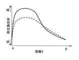
- FIG. 5 is a diagram showing an intake flow rate characteristic in the heat exchanger.
- FIG. 6 is a diagram showing temperature characteristics in the heat exchanger.
- FIG. 7 is a diagram showing the temperature change rate characteristic in the heat exchanger.
- FIG. 8 is a diagram showing heat exchange efficiency characteristics in the heat exchanger.
- FIG. 9 is a diagram showing the total intake heat dissipation amount in the heat exchanger.
- FIG. 1 is a schematic configuration diagram of an intake air cooling device for an internal combustion engine.
- FIG. 2 is a view of the intake air cooling device of the internal combustion engine along the arrow AR of FIG.
- FIG. 3 is
- FIG. 10 is a diagram showing an intake flow rate characteristic of a modified example.
- FIG. 11 is a diagram showing the temperature characteristics of the modified example.
- FIG. 12 is a diagram showing the temperature change rate characteristic of the modified example.
- FIG. 13 is a diagram showing the heat exchange efficiency characteristics of the modified example.
- FIG. 14 is a diagram showing the total intake heat received in the modified example.
- FIG. 15 is a diagram showing an intake air cooling device for an internal combustion engine according to a second embodiment.
- FIG. 16 is a diagram showing an intake air cooling device for an internal combustion engine according to a third embodiment.
- FIG. 1 is a schematic configuration diagram of an intake air cooling device (hereinafter, simply referred to as an intake air cooling device) 100A of an internal combustion engine.
- FIG. 2 is a view of the intake air cooling device 100A along the arrow AR of FIG.
- FIG. 3 is a view of the heat exchange section 1A in the I-I cross section of FIG. The distance X, the point A, and the point B shown in FIG. 1 will be described later.
- the intake air cooling device 100A is provided in the internal combustion engine 6 and cools the intake air of the internal combustion engine 6.
- the internal combustion engine 6 is a spark-ignition internal combustion engine with a supercharger, and in the present embodiment, it is an in-line 3-cylinder gasoline engine.
- the intake air cooling device 100A includes a heat exchange unit 1A, an intake control valve 2, an intake pipe 3, a collector 4, and an intake manifold 5.
- the intake air cooling device 100A corresponds to a heat exchange device.
- the heat exchange unit 1A exchanges heat between the introduced coolant W and the passing intake air.
- the coolant W is a heat medium and is used in a liquid phase state. That is, the heat exchange unit 1A constitutes a water-cooled heat exchange unit when cooling the intake air.
- the coolant W for example, the coolant of the internal combustion engine 6 can be used, including the case where the coolant circuit is not configured to have the internal combustion engine 6.
- the heat exchange unit 1A includes a heat exchanger 11 and a case 12.
- the heat exchanger 11 circulates the coolant W inside to exchange heat between the coolant W and the intake air.
- the case 12 accommodates the heat exchanger 11 and constitutes an intake passage for the intake air to pass through the heat exchanger 11.
- the heat exchanger 11 is an intercooler, and is incorporated in a coolant circuit that dissipates heat in a heat radiating part such as a radiator.
- the coolant circuit is configured to receive heat of the coolant W by the heat exchanger 11 and does not have a heat source for receiving the coolant W.
- the heat source is, for example, an internal combustion engine 6.
- the heat source may be a motor or the like.
- the heat exchange unit 1A constitutes a part of the coolant circuit by having the heat exchanger 11 incorporated in the coolant circuit.
- the coolant circuit corresponds to a heat medium circuit.
- the heat exchange unit 1A includes a coolant introduction port 13 and a coolant outlet 14.
- the coolant introduction port 13 and the coolant outlet 14 are provided at positions facing each other with respect to the heat exchange unit 1A.
- the coolant introduction port 13 is provided on one end side of the heat exchange portion 1A in the longitudinal direction (vertical direction in FIG. 1). Therefore, the coolant W flows through the heat exchange unit 1A in the longitudinal direction.
- the longitudinal direction of the heat exchange unit 1A corresponds to the cylinder arrangement direction of the internal combustion engine 6.
- the coolant inlet 13 corresponds to the heat medium inlet
- the coolant outlet 14 corresponds to the heat medium outlet.
- the intake control valve 2 controls the intake air that passes through the heat exchange unit 1A.
- the intake control valve 2 is arranged on the upstream side of the intake system with respect to the heat exchange unit 1A.
- the intake control valve 2 is provided in the intake pipe 3 and controls the flow rate of the flowing intake air by changing the degree of opening of the passage in the intake pipe 3.
- the intake control valve 2 is provided at a position facing the coolant introduction port 13 with respect to the heat exchange unit 1A.
- the intake control valve 2 provided in this way is provided on the other end side in the longitudinal direction of the heat exchange portion 1A.
- the intake pipe 3 is connected to the heat exchange unit 1A via the collector 4. Therefore, the intake air flows into the heat exchange unit 1A via the collector 4.
- the intake pipe 3 is connected to the collector 4 in a direction opposite to the coolant introduction direction of the coolant introduction port 13. Therefore, the intake pipe 3 circulates the intake air in the direction opposite to the coolant introduction direction of the coolant introduction port 13.
- the collector 4 temporarily stores the intake air.
- the collector 4 has a longitudinal direction in the cylinder arrangement direction and is connected to the case 12 of the heat exchange unit 1A.
- the collector 4 causes the intake air that has flowed in the direction opposite to the coolant introduction direction of the coolant introduction port 13 to flow into the heat exchange unit 1A.
- the collector 4 corresponds to the collector section.
- the collector 4 may be integrated with the heat exchange unit 1A.
- the portion of the integrated case on the upstream side of the intake system from the heat exchanger 11 can be grasped as the collector portion.
- the portion of the integrated case that houses the heat exchanger 11 and the heat exchanger 11 can be grasped as the heat exchanger 1A.
- the intake air that has passed through the heat exchange unit 1A flows into the intake manifold 5.
- the intake manifold 5 distributes intake air to each cylinder of the internal combustion engine 6.
- the intake air to each cylinder of the internal combustion engine 6 is made uniform.
- the intake air introduced into the heat exchange unit 1A is drifted due to the bending of the intake pipe 3 as described below.
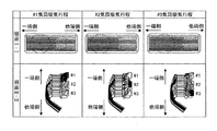
- FIG. 4 is a diagram showing a drift state of intake air.
- the I-I cross section is a view of the drift state of the intake air in the I-I cross section shown in FIG. 1, and the darker the portion, the higher the intake flow velocity.
- the II-II cross section is a view of the drift state of the intake air in the II-II cross section shown in FIG.
- the intake air is drifted as follows, coupled with the fact that the intake air is separated at the inner part of the bend of the intake pipe 3. That is, as shown by the broken circles on the I-I cross section, the intake air is from the center of the heat exchange unit 1A in the longitudinal direction in all of the intake stroke of the # 1 cylinder, the intake stroke of the # 2 cylinder, and the intake stroke of the # 3 cylinder. It drifts to the area on one end side. In this case, since heat exchange is performed in a state where the intake air is drifted, there is a concern that the intake air cannot be efficiently exchanged heat unless the intake air drift is particularly considered.
- the intake control valve 2 is provided at a position facing the coolant introduction port 13 with respect to the heat exchange unit 1A.
- the heat exchange unit 1A can obtain various characteristics as follows.
- FIGS. 5 to 8 are diagrams showing various characteristics in the heat exchange unit 1A.
- the vertical axis represents various parameters
- the horizontal axis represents the distance X shown in FIG.
- the distance X is the distance in the longitudinal direction of the heat exchange unit 1A, and indicates the distance from the point A.
- the point A side corresponds to one end side in the longitudinal direction of the heat exchange portion 1A
- the point B side corresponds to the other end side in the longitudinal direction of the heat exchange portion 1A.
- FIGS. 6 to 8 the case of the comparative example is also shown by a broken line.
- a comparative example shows a case where the coolant introduction port 13 and the intake control valve 2 are provided on the B point side with respect to the heat exchange unit 1A.
- the coolant outlet 14 is provided on the point A side.
- the intake flow rate increases from the center of the distance X to the point A. This is because the intake air is drifted as described above. This tendency is the same for the intake flow velocity.
- the intake air temperature is constant regardless of the distance X.
- the temperature of the coolant W is lower than the intake air temperature, and becomes higher from the point A side toward the point B side. That is, in the heat exchange unit 1A, a temperature gradient (temperature change) in which the temperature of the coolant W tends to gradually increase from the point A side to the point B side is formed. This is because the coolant W flows from the point A side to the point B side while exchanging heat. In the case of the comparative example, since the coolant W flows from the point B side to the point A side, the temperature of the coolant W becomes higher from the point B side to the point A side.
- the temperature change rate of the coolant W becomes smaller from the point A side to the point B side. This is because the temperature difference between the coolant W and the intake air is larger toward the point A side, and heat exchange is promoted. Therefore, in the case of the present embodiment, heat exchange is further promoted on the point A side where the intake flow rate increases due to the drift.
- the temperature difference between the coolant W and the intake air becomes large on the point B side. Therefore, in the case of the comparative example, the temperature change rate of the coolant W decreases from the point B side to the point A side, and heat exchange is further promoted on the B point side where the intake air flow rate decreases.
- the heat exchange efficiency is high from the center of the distance X to the point A. This is because the temperature difference between the coolant W and the intake air is large on the point A side where the intake air flows unevenly.
- the heat exchange efficiency is high from the center of the distance X to the point A, but is lower than that in the case of the present embodiment. This is because the intake air flows unevenly to the point A side, while the temperature difference between the coolant W and the intake air is small on the point A side.
- FIG. 9 is a diagram showing the total heat dissipation amount of the intake air in the heat exchange unit 1A, and it can be seen that the total heat dissipation amount of the intake air is also larger in the case of the present embodiment than in the case of the comparative example.
- the intake air cooling device 100A constitutes a heat exchange device that exchanges heat with the intake air of the internal combustion engine 6.
- the intake air cooling device 100A includes a heat exchange unit 1A that exchanges heat between the introduced coolant W and the passing intake air, and an intake air control valve 2 that controls the intake air that passes through the heat exchange unit 1A.
- the coolant introduction port 13 of the heat exchange unit 1A and the intake control valve 2 are provided at positions facing each other with respect to the heat exchange unit 1A.
- the intake air is circulated in the direction opposite to the cooling liquid introduction direction, and the intake air circulated in this way flows into the heat exchange unit 1A, while the intake flow rate in the heat exchange unit 1A is caused by this. It becomes possible to introduce the coolant W in a place where the amount of the coolant W increases. Therefore, a large temperature difference is generated between the intake air and the coolant W at the location, and the intake air can be efficiently exchanged for heat to be cooled.
- the coolant introduction port 13 and the coolant outlet 14 are provided at positions facing each other with respect to the heat exchange unit 1A.
- the flow of the coolant W in the heat exchange unit 1A can be unidirectional, and a larger temperature difference is generated between the intake air and the coolant W at the place where the intake air flow rate is large. be able to. Therefore, according to such a configuration, as compared with the case where, for example, the heat exchange unit 1A is provided with the coolant outlet 14 on the same side as the coolant introduction port 13, the intake air is more efficiently exchanged for heat for cooling. can do.
- the intake air flows into the heat exchange unit 1A via the collector 4.
- the heat exchange section 1A and the collector 4 have a longitudinal direction in the cylinder arrangement direction of the internal combustion engine 6.
- the coolant introduction port 13 is provided on one end side in the longitudinal direction of the heat exchange portion 1A.
- the intake control valve 2 causes the intake air to flow into the collector 4 from the other end side in the longitudinal direction of the heat exchange portion 1A.
- a temperature gradient in which the temperature of the coolant W tends to gradually increase from one end side in the longitudinal direction to the other end side of the heat exchange portion 1A is formed in the heat exchange portion 1A, and one end in the longitudinal direction is formed.
- a large temperature difference can be generated between the intake air that drifts to the side and the coolant W. Therefore, according to such a configuration, the intake air can be efficiently exchanged for heat and cooled.
- the intake air cooling device 100A may be used for heating the intake air.
- the coolant circuit that distributes the coolant W to the heat exchange unit 1A can be configured to have a heat source.
- the heat source can receive heat from the coolant W, and the heat exchange unit 1A can dissipate heat from the coolant W.
- FIGS. 10 to 13 Various characteristics of the heat exchange unit 1A in this case are shown in FIGS. 10 to 13, and the total amount of heat received by the intake air is shown in FIG.
- the characteristics of the intake air flow rate are the same as those in FIG.
- the temperature of the coolant W is higher than the intake air temperature, and a temperature gradient is formed in which the temperature of the coolant W tends to gradually decrease from the point A side to the point B side. That is, also in this case, a large temperature difference between the coolant W and the intake air is secured on the point A side.
- a temperature gradient is formed in which the temperature of the coolant W tends to gradually decrease from the point B side toward the point A side.
- the temperature change rate of the coolant W decreases from the point A side to the point B side. That is, in this case as well, the heat exchange of the coolant W is further promoted on the point A side. In the case of the comparative example, the heat exchange of the coolant W is further promoted on the B point side where the intake air flow rate is small. As a result, as shown in FIG. 13, even when the intake air is heated, the heat exchange efficiency is higher between the center of the distance X and the point A than in the case of the comparative example. Further, as shown in FIG. 14, the total amount of heat received by the intake air in the heat exchange unit 1A is also larger than that in the case of the comparative example.
- the intake air cooling device 100A is used for heating the intake air, a large temperature difference can be generated between the intake air and the coolant W at a place where the intake air flow rate is large. As a result, in this case, the intake air can be efficiently exchanged for heat to be heated.
- FIG. 15 is a diagram showing an intake air cooling device 100B according to a second embodiment.
- the intake air cooling device 100B is configured in the same manner as the intake air cooling device 100A except that the heat exchange unit 1B is provided instead of the heat exchange unit 1A.
- the heat exchange unit 1B is incorporated in two systems of coolant circuits, and is configured to exchange heat between each of the coolants W flowing through the two systems of coolant circuits and the intake air.
- the coolant introduction port 13 and the coolant outlet 14 are provided for two systems, and the built-in heat exchanger 11 is also provided for two systems. That is, in the present embodiment, the heat exchanger 11 is composed of two heat exchangers.
- the heat exchangers for two systems may be composed of two individual heat exchangers, or may be composed of two heat exchangers integrated. In the present embodiment, the heat exchangers for the two systems are provided adjacent to each other in the direction orthogonal to the longitudinal direction (the direction connecting the collector 4 and the intake manifold 5).
- the two systems of coolant circuits are composed of a high-temperature coolant circuit in which the high-temperature coolant WH flows as the coolant W and a low-temperature coolant circuit in which the low-temperature coolant WL flows as the coolant W.
- the high-temperature coolant circuit has a heat source, and the high-temperature coolant WH is configured to receive heat at the heat source and dissipate heat at the heat exchange unit 1B.
- the low-temperature coolant circuit is configured such that the low-temperature coolant WL receives heat in the heat exchange section 1B and dissipates heat in a heat dissipation section such as a radiator.
- the high temperature coolant circuit is provided on the collector 4 side of the collector 4 and the intake manifold 5 in the heat exchange unit 1B, and the low temperature coolant circuit is provided on the opposite side.
- the arrangement of the high temperature coolant circuit and the low temperature coolant circuit in the heat exchange unit 1B may be interchanged.
- the heat exchange unit 1B exchanges heat between each of the coolants W flowing through the two systems of coolant circuits, that is, the high temperature coolant WH and the low temperature coolant WL and the intake air.
- the intake air can be efficiently exchanged heat with each of the coolants W flowing through the two systems of coolant circuits. That is, even with such a configuration, a large temperature difference can be generated between the intake air and the coolant W at a place where the intake air flow rate is large, and the intake air can be efficiently exchanged with heat.
- the heat exchange unit 1B heats the intake air when the temperature of the high temperature coolant WH is higher than the intake air temperature in the high temperature coolant circuit.
- the intake air can be efficiently heated in the high temperature coolant circuit which is one of the two coolant circuits.
- FIG. 16 is a diagram showing an intake air cooling device 100C according to a third embodiment.
- the intake air cooling device 100C is configured in the same manner as the intake air cooling device 100B except that the heat exchange unit 1C is provided instead of the heat exchange unit 1B.
- the heat exchange unit 1C is configured in the same manner as the heat exchange unit 1B except that it further has a heat insulating layer 15.
- the heat insulating layer 15 is provided between the high coolant circuit and the low coolant circuit in the heat exchange unit 1C, that is, between two heat exchangers constituting two heat exchangers.
- the heat insulating layer 15 has a structure through which intake air can pass (for example, a slit-shaped porous structure or a mesh structure), and prevents direct contact between the high-temperature coolant circuit and the low-temperature coolant circuit in the heat exchange unit 1C.
- a heat insulating material such as resin or metal having a higher heat insulating property than the member of the heat exchanger can be used.
- the heat insulating layer 15 may be composed of a passage space of the heat exchange unit 1C formed between the high temperature coolant circuit and the low temperature coolant circuit in the heat exchange unit 1C.
- the heat insulating layer 15 may be configured by providing the high temperature coolant circuit and the low temperature coolant circuit separately in the heat exchange unit 1C.
- the heat exchange unit 1C has a heat insulating layer 15 between the high temperature coolant circuit and the low temperature coolant circuit.
- the heat insulating layer 15 can suppress the transfer of heat between the high temperature coolant circuit and the low temperature coolant circuit. Therefore, it is possible to suppress the temperature of the coolant W in each coolant circuit from changing due to heat transfer, and it is possible to secure a large temperature difference between the intake air and the coolant W at a place where the intake air flow rate increases accordingly. it can. As a result, the intake air can be heat-exchanged more efficiently in each coolant circuit.
Abstract
吸気冷却装置100Aは、内燃機関6の吸気の熱交換を行う熱交換装置を構成する。吸気冷却装置100Aは、導入される冷却液W及び通過する吸気間で熱交換を行う熱交換部1Aと、熱交換部1Aを通過させる吸気の制御を行う吸気制御弁2とを備える。熱交換部1Aの冷却液導入口13と吸気制御弁2とは、熱交換部1Aに対して互いに相対する位置に設けられる。
Description
本発明は、内燃機関の吸気の熱交換を行う熱交換装置に関する。
JP2012−102667Aには、水冷式のインタークーラに対し冷却水を導入する冷却水循環回路が吸気管と同じ側から接続された吸気冷却装置が開示されている。
吸気の熱交換を行う熱交換装置では、熱交換部に導入される吸気が吸気系の曲がりにより偏流し得る。この場合、吸気が偏流した状態で熱交換が行われることから、吸気を効率的に熱交換させることができない場合がある。
本発明はこのような課題に鑑みてなされたもので、吸気を効率的に熱交換させることを目的とする。
課題を解決するための手段
課題を解決するための手段
本発明のある態様の熱交換装置は、内燃機関の吸気の熱交換を行う熱交換装置であって、導入される熱媒体と通過する吸気とを熱交換させる熱交換部と、熱交換部を通過させる吸気の制御を行う吸気制御弁と、を備える。熱交換部の熱媒体導入口と吸気制御弁とは、熱交換部に対して互いに相対する位置に設けられる。
この態様によれば、冷却液導入方向と相対する方向に向かって吸気を流通させ、このように流通させた吸気を熱交換部に流入させる一方、これにより熱交換部において吸気流量が多くなる箇所に冷却液を導入することが可能になる。このため、当該箇所において吸気と冷却液との間で大きな温度差を生じさせ、吸気を効率的に熱交換させることが可能になる。
以下、添付図面を参照しながら本発明の実施形態について説明する。
(第1実施形態)
図1は内燃機関の吸気冷却装置(以下、単に吸気冷却装置と称す)100Aの概略構成図である。図2は、図1の矢印ARに沿って吸気冷却装置100Aを見た図である。図3は、図1のI−I断面で熱交換部1Aを見た図である。図1に示す距離X、点A、点Bについては後述する。
図1は内燃機関の吸気冷却装置(以下、単に吸気冷却装置と称す)100Aの概略構成図である。図2は、図1の矢印ARに沿って吸気冷却装置100Aを見た図である。図3は、図1のI−I断面で熱交換部1Aを見た図である。図1に示す距離X、点A、点Bについては後述する。
吸気冷却装置100Aは、内燃機関6に設けられ内燃機関6の吸気を冷却する。内燃機関6は過給機付きの火花点火内燃機関とされ、本実施形態では直列3気筒のガソリンエンジンとされる。吸気冷却装置100Aは、熱交換部1Aと、吸気制御弁2と、吸気管3と、コレクタ4と、インテークマニホールド5とを備える。吸気冷却装置100Aは、熱交換装置に相当する。
熱交換部1Aは、導入される冷却液Wと通過する吸気とを熱交換させる。冷却液Wは熱媒体であり、液相状態で用いられる。つまり、熱交換部1Aは吸気を冷却するにあたり、水冷式の熱交換部を構成する。冷却液Wには例えば、冷却液回路が内燃機関6を有して構成されない場合を含め、内燃機関6の冷却液を用いることができる。
熱交換部1Aは、熱交換器11とケース12とを備える。熱交換器11は内部に冷却液Wを流通させ、冷却液Wと吸気とを熱交換させる。ケース12は、熱交換器11を収容するとともに、吸気が熱交換器11を通過するための吸気通路を構成する。
熱交換器11はインタークーラであり、ラジエータ等の放熱部で放熱する冷却液回路に組み込まれる。当該冷却液回路は、熱交換器11で冷却液Wを受熱させる構成とされ、冷却液Wを受熱させる熱源を有しない構成とされる。熱源は例えば内燃機関6である。熱源はモータ等であってもよい。熱交換部1Aは、冷却液回路に組み込まれる熱交換器11を有することで、冷却液回路の一部を構成する。冷却液回路は熱媒体回路に相当する。
熱交換部1Aは、冷却液導入口13と冷却液出口14とを備える。冷却液導入口13と冷却液出口14とは、熱交換部1Aに対して互いに相対する位置に設けられる。冷却液導入口13は、熱交換部1Aの長手方向(図1の上下方向)一端側に設けられる。このため、熱交換部1Aには冷却液Wが長手方向に流通する。熱交換部1Aの長手方向は、内燃機関6の気筒配列方向に対応する。冷却液導入口13は熱媒体導入口に相当し、冷却液出口14は熱媒体出口に相当する。
吸気制御弁2は、熱交換部1Aを通過させる吸気の制御を行う。吸気制御弁2は、熱交換部1Aよりも吸気系上流側に配置される。吸気制御弁2は、吸気管3内に設けられ、吸気管3内の通路の開放度合いを変化させることにより、流通する吸気の流量を制御する。吸気制御弁2は、熱交換部1Aに対して冷却液導入口13と互いに相対する位置に設けられる。このように設けられた吸気制御弁2は、熱交換部1Aの長手方向他端側に設けられる。
吸気管3は、コレクタ4を介して熱交換部1Aに接続する。従って、熱交換部1Aには、コレクタ4を介して吸気が流入する。吸気管3は、冷却液導入口13の冷却液導入方向と相対する向きでコレクタ4に接続する。このため、吸気管3は、冷却液導入口13の冷却液導入方向と相対する方向に向かって吸気を流通させる。
コレクタ4は、吸気を一時的に貯留する。コレクタ4は、熱交換部1A同様、気筒配列方向に長手方向を有し、熱交換部1Aのケース12に接続される。コレクタ4は、冷却液導入口13の冷却液導入方向と相対する方向に向かって流通してきた吸気を熱交換部1Aに流入させる。コレクタ4はコレクタ部に相当する。
コレクタ4は、熱交換部1Aと一体構成とされてもよい。この場合、一体化されたケースのうち熱交換器11よりも吸気系上流側の部分をコレクタ部として把握することができる。また、一体化されたケースのうち熱交換器11を収容する部分、及び熱交換器11を熱交換部1Aとして把握することができる。
熱交換部1Aを流通した吸気は、インテークマニホールド5に流入する。インテークマニホールド5は、内燃機関6の各気筒に吸気を分配する。
ところで、コレクタ4では内燃機関6の各気筒への吸気の均一化が図られる。しかしながら、熱交換部1Aに導入される吸気は、吸気管3の曲がりによって次に説明するように偏流する。
図4は、吸気の偏流状態を示す図である。I−I断面は、図1に示すI−I断面で吸気の偏流状態を見た図であり、濃い部分ほど吸気流速が高いことを示す。II−II断面は、図2に示すII−II断面で吸気の偏流状態を見た図である。
図4に示されるように、吸気は、吸気管3の曲がり内側の部分で剥離することとも相俟って、次のように偏流する。すなわち、吸気は、I−I断面に破線の丸印で示すように、#1気筒の吸気行程、#2気筒の吸気行程、#3気筒吸気行程でともに、熱交換部1Aの長手方向中央から一端側にかけた領域に偏流する。この場合、吸気が偏流した状態で熱交換が行われることから、吸気の偏流が特段考慮されていない場合には、吸気を効率的に熱交換させることができないことが懸念される。
このような事情に鑑み、吸気冷却装置100Aでは、吸気制御弁2が熱交換部1Aに対して冷却液導入口13と互いに相対する位置に設けられる。結果、熱交換部1Aでは次のような各種特性が得られる。
図5から図8は、熱交換部1Aにおける各種特性を示す図である。図5から図8において、縦軸は各種パラメータを示し、横軸は図1に示す距離Xを示す。距離Xは、熱交換部1Aの長手方向の距離であり、点Aからの距離を示す。点A側は熱交換部1Aの長手方向一端側に対応し、点B側は熱交換部1Aの長手方向他端側に対応する。図6から図8では、比較例の場合を破線で併せて示す。比較例は、熱交換部1Aに対して冷却液導入口13と吸気制御弁2とをB点側に設けた場合を示す。比較例では、冷却液出口14は点A側に設けられる。
図5に示すように、吸気流量は距離Xの中央から点Aの間で大きくなっている。これは前述のように吸気が偏流するためである。この傾向は吸気流速についても同様である。
図6に示すように、吸気温度は、距離Xによらず一定となっている。冷却液Wの温度は、吸気温度よりも低くなっており、且つ点A側から点B側に向かうほど高くなっている。つまり、熱交換部1Aでは、点A側から点B側に向かって次第に冷却液Wの温度が高くなる傾向の温度勾配(温度変化)が形成される。これは、点A側から点B側に向かって冷却液Wが熱交換をしながら流通するためである。比較例の場合、点B側から点A側に冷却液Wが流通するため、冷却液Wの温度が点B側から点A側に向かうほど高くなる。
図7に示すように、冷却液Wの温度変化率は、点A側から点B側に向かうほど小さくなる。これは、点A側ほど冷却液Wと吸気との温度差が大きく、熱交換が促進されるためである。このため、本実施形態の場合は、偏流により吸気流量が多くなるA点側で熱交換がより促進される。比較例の場合、点B側で冷却液Wと吸気との温度差が大きくなる。このため、比較例の場合、点B側から点A側に向かうほど冷却液Wの温度変化率が小さくなり、吸気流量が少なくなるB点側で熱交換がより促進される。
図8に示すように、本実施形態の場合、熱交換効率は距離Xの中央から点Aの間で高くなっている。これは、吸気が偏流する点A側で冷却液Wと吸気との温度差が大きくなっているためである。比較例の場合、熱交換効率は距離Xの中央から点Aの間で高くなっているものの、本実施形態の場合よりも低い。これは、点A側に吸気が偏流する一方で、点A側では冷却液Wと吸気との温度差が小さいためである。図9は、熱交換部1Aにおける吸気の総放熱量を示す図であり、吸気の総放熱量についても、本実施形態の場合のほうが比較例の場合よりも大きいことがわかる。
次に、本実施形態の主な作用効果について説明する。
吸気冷却装置100Aは、内燃機関6の吸気の熱交換を行う熱交換装置を構成する。吸気冷却装置100Aは、導入される冷却液W及び通過する吸気間で熱交換を行う熱交換部1Aと、熱交換部1Aを通過させる吸気の制御を行う吸気制御弁2とを備える。熱交換部1Aの冷却液導入口13と吸気制御弁2とは、熱交換部1Aに対して互いに相対する位置に設けられる。
このような構成によれば、冷却液導入方向と相対する方向に向かって吸気を流通させ、このように流通させた吸気を熱交換部1Aに流入させる一方、これにより熱交換部1Aにおいて吸気流量が多くなる箇所に冷却液Wを導入することが可能になる。このため、当該箇所において吸気と冷却液Wとの間で大きな温度差を生じさせ、吸気を効率的に熱交換させて冷却することが可能になる。
本実施形態では、冷却液導入口13と冷却液出口14とは、熱交換部1Aに対して互いに相対する位置に設けられる。
このような構成によれば、熱交換部1Aにおける冷却液Wの流れを一方向にすることができ、吸気流量が多くなる箇所において吸気と冷却液Wとの間でより大きな温度差を生じさせることができる。このためこのような構成によれば、例えば熱交換部1Aに対して冷却液導入口13と同じ側に冷却液出口14を設けた場合と比較し、吸気をより効率的に熱交換させて冷却することができる。
本実施形態では、熱交換部1Aにはコレクタ4を介して吸気が流入する。熱交換部1Aとコレクタ4とは、内燃機関6の気筒配列方向に長手方向を有する。冷却液導入口13は、熱交換部1Aの長手方向一端側に設けられる。吸気制御弁2は、熱交換部1Aの長手方向他端側からコレクタ4に吸気を流入させる。
このような構成によれば、熱交換部1Aの長手方向一端側から他端側に向かって次第に冷却液Wの温度が高くなる傾向の温度勾配を熱交換部1Aに形成して、長手方向一端側に偏流する吸気と冷却液Wとの間で大きな温度差を生じさせることができる。このためこのような構成によれば、吸気を効率的に熱交換させて冷却することができる。
吸気冷却装置100Aは吸気の加熱に用いられてもよい。この場合、熱交換部1Aに冷却液Wを流通させる冷却液回路を、熱源を有した構成とすることができる。この場合、熱源で冷却液Wに受熱させ、熱交換部1Aで冷却液Wから放熱させることができる。この場合の熱交換部1Aにおける各種特性を図10から図13に、吸気の総受熱量を図14にそれぞれ示す。
図10に示すように、吸気流量の特性は図5と同じである。図11に示すように、冷却液Wの温度は吸気温度よりも高くなっており、A点側からB点側に向かって次第に冷却液Wの温度が低下する傾向の温度勾配が形成される。つまりこの場合も、A点側で冷却液Wと吸気との温度差が大きく確保される。比較例の場合は、B点側から熱交換部1Aに冷却液Wが導入されるので、B点側からA点側に向かって次第に冷却液Wの温度が低下する傾向の温度勾配が形成される。
図12に示すように、冷却液Wの温度変化率はA点側からB点側に向うほど小さくなる。つまりこの場合も、A点側で冷却液Wの熱交換がより促進される。比較例の場合は、吸気流量が少ないB点側で冷却液Wの熱交換がより促進される。結果、図13に示すように、吸気を加熱する場合も、熱交換効率は距離Xの中央からA点の間で比較例の場合よりも大きくなる。また、図14に示すように、熱交換部1Aにおける吸気の総受熱量も比較例の場合よりも大きくなる。
このように、吸気冷却装置100Aは、吸気の加熱に用いられる場合にも、吸気流量が多くなる箇所において吸気と冷却液Wとで大きな温度差を生じさせることができる。結果、この場合には吸気を効率的に熱交換させて加熱することができる。
(第2実施形態)
図15は、第2実施形態にかかる吸気冷却装置100Bを示す図である。吸気冷却装置100Bは、熱交換部1Aの代わりに熱交換部1Bを備える点以外、吸気冷却装置100Aと同様に構成される。熱交換部1Bは2系統の冷却液回路に組み込まれ、2系統の冷却液回路を流通する冷却液Wそれぞれと吸気との間で熱交換を行うように構成される。
図15は、第2実施形態にかかる吸気冷却装置100Bを示す図である。吸気冷却装置100Bは、熱交換部1Aの代わりに熱交換部1Bを備える点以外、吸気冷却装置100Aと同様に構成される。熱交換部1Bは2系統の冷却液回路に組み込まれ、2系統の冷却液回路を流通する冷却液Wそれぞれと吸気との間で熱交換を行うように構成される。
このように構成される熱交換部1Bでは、冷却液導入口13及び冷却液出口14が2系統分設けられ、内蔵する熱交換器11も2系統分設けられる。つまり、本実施形態では熱交換器11は2系統分の熱交換器により構成される。2系統分の熱交換器は2つの個別の熱交換器により構成されてもよく、2つの熱交換器が一体化されたものにより構成されてもよい。本実施形態では、2系統分の熱交換器は長手方向に直交する方向(コレクタ4とインテークマニホールド5とを結ぶ方向)に隣接して設けられる。
2系統の冷却液回路は、冷却液Wとして高温冷却液WHが流通する高温冷却液回路、及び冷却液Wとして低温冷却液WLが流通する低温冷却液回路により構成される。高温冷却液回路は熱源を有し、高温冷却液WHが熱源で受熱し熱交換部1Bで放熱するように構成される。低温冷却液回路は、低温冷却液WLが熱交換部1Bで受熱しラジエータ等の放熱部で放熱するように構成される。高温冷却液回路は、熱交換部1Bにおいてコレクタ4及びインテークマニホールド5のうちコレクタ4側に設けられ、低温冷却液回路はその反対側に設けられる。熱交換部1Bにおける高温冷却液回路及び低温冷却液回路の配置は入れ替えられてもよい。
次に、本実施形態の主な作用効果について説明する。
吸気冷却装置100Bでは、熱交換部1Bは、2系統の冷却液回路を流通する冷却液Wそれぞれ、つまり高温冷却液WH及び低温冷却液WLと吸気との間で熱交換を行う。
このような構成によれば、2系統の冷却液回路を流通する冷却液Wそれぞれとの間で吸気を効率的に熱交換させることができる。つまり、このような構成でも吸気流量が多くなる箇所において吸気と冷却液Wとの間で大きな温度差を生じさせ、吸気を効率的に熱交換させることができる。
吸気冷却装置100Bでは、熱交換部1Bは、高温冷却液回路において高温冷却液WHの温度が吸気温度よりも高い場合には吸気を加熱する。
このような構成によれば、2系統の冷却液回路のうちの1系統の冷却液回路である高温冷却液回路において、吸気の加熱を効率的に行うことができる。
(第3実施形態)
図16は、第3実施形態にかかる吸気冷却装置100Cを示す図である。吸気冷却装置100Cは、熱交換部1Bの代わりに熱交換部1Cを備える点以外、吸気冷却装置100Bと同様に構成される。熱交換部1Cは、断熱層15をさらに有する点以外、熱交換部1Bと同様に構成される。
図16は、第3実施形態にかかる吸気冷却装置100Cを示す図である。吸気冷却装置100Cは、熱交換部1Bの代わりに熱交換部1Cを備える点以外、吸気冷却装置100Bと同様に構成される。熱交換部1Cは、断熱層15をさらに有する点以外、熱交換部1Bと同様に構成される。
断熱層15は、熱交換部1Cにおいて高冷却液回路及び低冷却液回路間、つまり2系統分の熱交換器を構成する2つの熱交換器間に設けられる。断熱層15は、吸気が通過可能な構造(例えば、スリット状の多孔構造や網目構造)を有し、熱交換部1Cにおける高温冷却液回路と低温冷却液回路との直接接触を妨げる。断熱層15には例えば、熱交換器の部材よりも断熱性が高い樹脂、金属等の断熱材を用いることができる。断熱層15は、熱交換部1Cにおいて高温冷却液回路及び低温冷却液回路間に形成された熱交換部1Cの通路空間により構成されてもよい。換言すれば、断熱層15は、熱交換部1Cにおいて高温冷却液回路と低温冷却液回路とを離間して設けることにより構成されてもよい。
次に、本実施形態の主な作用効果について説明する。
吸気冷却装置100Cでは、熱交換部1Cは、高温冷却液回路及び低温冷却液回路間に断熱層15を有する。
このような構成によれば、断熱層15により高温冷却液回路及び低温冷却液回路間の熱の移動を抑制できる。このため、各冷却液回路における冷却液Wの温度が熱の移動により変化することを抑制でき、その分、吸気流量が多くなる箇所において吸気と冷却液Wとで大きな温度差を確保することができる。結果、その分、各冷却液回路において吸気をより効率的に熱交換させることができる。
以上、本発明の実施形態について説明したが、上記実施形態は本発明の適用例の一部を示したに過ぎず、本発明の技術的範囲を上記実施形態の具体的構成に限定する趣旨ではない。
Claims (6)
- 内燃機関の吸気の熱交換を行う熱交換装置であって、
導入される熱媒体と通過する吸気とを熱交換させる熱交換部と、
前記熱交換部を通過させる吸気の制御を行う吸気制御弁と、
を備え、
前記熱交換部の熱媒体導入口と前記吸気制御弁とは、前記熱交換部に対して互いに相対する位置に設けられる、
熱交換装置。 - 請求項1に記載の熱交換装置であって、
前記熱媒体導入口と前記熱交換部の熱媒体出口とは、前記熱交換部に対して互いに相対する位置に設けられる、
熱交換装置。 - 請求項1又は2に記載の熱交換装置であって、
前記熱交換部は、2系統の熱媒体回路を流通する熱媒体それぞれと吸気との間で熱交換を行う、
熱交換装置。 - 請求項3に記載の熱交換装置であって、
前記2系統の熱媒体回路のうち1系統の熱媒体回路は熱源を有して構成され、
前記熱交換部は、前記1系統の熱媒体回路において熱媒体温度が吸気温度より高い場合には吸気を加熱する、
熱交換装置。 - 請求項3又は4に記載の熱交換装置であって、
前記熱交換部は、前記2系統の熱媒体回路間に断熱層を有する、
熱交換装置。 - 請求項1から5いずれか1項に記載の熱交換装置であって、
前記熱交換部には、吸気を一時的に貯留するコレクタ部を介して吸気が流入し、
前記熱交換部と前記コレクタ部とは、前記内燃機関の気筒配列方向に長手方向を有し、
前記熱媒体導入口は、前記熱交換部の長手方向一端側に設けられ、
前記吸気制御弁は、前記熱交換部の長手方向他端側から前記コレクタ部に吸気を流入させる、
熱交換装置。
Priority Applications (5)
| Application Number | Priority Date | Filing Date | Title |
|---|---|---|---|
| PCT/IB2019/000637 WO2020254847A1 (ja) | 2019-06-21 | 2019-06-21 | 熱交換装置 |
| US17/620,825 US11674480B2 (en) | 2019-06-21 | 2019-06-21 | Heat exchange device |
| JP2021528009A JP7215575B2 (ja) | 2019-06-21 | 2019-06-21 | 熱交換装置 |
| CN201980097714.XA CN114008312B (zh) | 2019-06-21 | 2019-06-21 | 热交换装置 |
| EP19933251.1A EP3988769A4 (en) | 2019-06-21 | 2019-06-21 | HEAT EXCHANGE DEVICE |
Applications Claiming Priority (1)
| Application Number | Priority Date | Filing Date | Title |
|---|---|---|---|
| PCT/IB2019/000637 WO2020254847A1 (ja) | 2019-06-21 | 2019-06-21 | 熱交換装置 |
Publications (1)
| Publication Number | Publication Date |
|---|---|
| WO2020254847A1 true WO2020254847A1 (ja) | 2020-12-24 |
Family
ID=74040134
Family Applications (1)
| Application Number | Title | Priority Date | Filing Date |
|---|---|---|---|
| PCT/IB2019/000637 WO2020254847A1 (ja) | 2019-06-21 | 2019-06-21 | 熱交換装置 |
Country Status (5)
| Country | Link |
|---|---|
| US (1) | US11674480B2 (ja) |
| EP (1) | EP3988769A4 (ja) |
| JP (1) | JP7215575B2 (ja) |
| CN (1) | CN114008312B (ja) |
| WO (1) | WO2020254847A1 (ja) |
Citations (5)
| Publication number | Priority date | Publication date | Assignee | Title |
|---|---|---|---|---|
| JP2012036805A (ja) * | 2010-08-06 | 2012-02-23 | Denso Corp | 熱交換部材、および、それを用いた吸気システム |
| JP2012102667A (ja) | 2010-11-10 | 2012-05-31 | Denso Corp | 吸気冷却装置 |
| US20160003128A1 (en) * | 2012-07-13 | 2016-01-07 | Delphi Technologies, Inc. | Supercharge air cooler |
| JP2016211435A (ja) * | 2015-05-08 | 2016-12-15 | マツダ株式会社 | エンジンの吸気冷却装置 |
| JP2019094856A (ja) * | 2017-11-24 | 2019-06-20 | トヨタ自動車株式会社 | 内燃機関の制御装置 |
Family Cites Families (13)
| Publication number | Priority date | Publication date | Assignee | Title |
|---|---|---|---|---|
| GB603112A (en) * | 1943-03-10 | 1948-06-09 | Girodin Marius Georges Henri | Improvements in or relating to systems of heat exchange |
| JPS5935674U (ja) | 1982-08-31 | 1984-03-06 | 日野自動車株式会社 | インテ−クパイプ |
| US6293264B1 (en) * | 1997-10-30 | 2001-09-25 | James K. Middlebrook | Supercharger aftercooler for internal combustion engines |
| JP4448636B2 (ja) * | 2001-09-28 | 2010-04-14 | ヤンマー株式会社 | 内燃機関の給気冷却装置 |
| DE102007030464A1 (de) * | 2007-06-29 | 2009-01-08 | Volkswagen Ag | Saugrohr für eine Brennkraftmaschine |
| JP4853481B2 (ja) | 2008-02-29 | 2012-01-11 | 株式会社デンソー | 内燃機関の吸気装置 |
| EP2412950B1 (en) * | 2009-03-23 | 2015-12-02 | Calsonic Kansei Corporation | Charge air cooler, cooling system, and intake control system |
| JP5948883B2 (ja) | 2012-01-17 | 2016-07-06 | マツダ株式会社 | エンジンの吸気装置 |
| JP6026825B2 (ja) | 2012-09-06 | 2016-11-16 | 株式会社デンソー | 内燃機関の吸気装置 |
| MX2017010454A (es) * | 2015-02-23 | 2017-11-28 | Nissan Motor | Estructura de tuberias del sistema de admision de motor de combustion interna. |
| JP6641940B2 (ja) * | 2015-12-02 | 2020-02-05 | 三菱自動車工業株式会社 | 内燃機関の吸気冷却装置 |
| US10544727B2 (en) * | 2016-03-31 | 2020-01-28 | Denso Corporation | Intercooler |
| JP6601338B2 (ja) | 2016-07-20 | 2019-11-06 | トヨタ自動車株式会社 | ダクト構造 |
-
2019
- 2019-06-21 JP JP2021528009A patent/JP7215575B2/ja active Active
- 2019-06-21 US US17/620,825 patent/US11674480B2/en active Active
- 2019-06-21 WO PCT/IB2019/000637 patent/WO2020254847A1/ja unknown
- 2019-06-21 CN CN201980097714.XA patent/CN114008312B/zh active Active
- 2019-06-21 EP EP19933251.1A patent/EP3988769A4/en active Pending
Patent Citations (5)
| Publication number | Priority date | Publication date | Assignee | Title |
|---|---|---|---|---|
| JP2012036805A (ja) * | 2010-08-06 | 2012-02-23 | Denso Corp | 熱交換部材、および、それを用いた吸気システム |
| JP2012102667A (ja) | 2010-11-10 | 2012-05-31 | Denso Corp | 吸気冷却装置 |
| US20160003128A1 (en) * | 2012-07-13 | 2016-01-07 | Delphi Technologies, Inc. | Supercharge air cooler |
| JP2016211435A (ja) * | 2015-05-08 | 2016-12-15 | マツダ株式会社 | エンジンの吸気冷却装置 |
| JP2019094856A (ja) * | 2017-11-24 | 2019-06-20 | トヨタ自動車株式会社 | 内燃機関の制御装置 |
Non-Patent Citations (1)
| Title |
|---|
| See also references of EP3988769A4 |
Also Published As
| Publication number | Publication date |
|---|---|
| EP3988769A4 (en) | 2022-08-03 |
| EP3988769A1 (en) | 2022-04-27 |
| CN114008312A (zh) | 2022-02-01 |
| US11674480B2 (en) | 2023-06-13 |
| US20220412294A1 (en) | 2022-12-29 |
| JP7215575B2 (ja) | 2023-01-31 |
| JPWO2020254847A1 (ja) | 2020-12-24 |
| CN114008312B (zh) | 2023-12-26 |
Similar Documents
| Publication | Publication Date | Title |
|---|---|---|
| US8191615B2 (en) | Linked heat exchangers having three fluids | |
| KR101765582B1 (ko) | 차량용 열교환기 | |
| JP6281467B2 (ja) | インタークーラ | |
| KR101776718B1 (ko) | 차량용 열교환기 | |
| US20130269663A1 (en) | Exhaust-gas heat exchange device | |
| JP2013113578A (ja) | 車両用熱交換器 | |
| JP2003232582A (ja) | 空気調和装置 | |
| ATE364826T1 (de) | Wärmetauschermodul mit hauptkühler und nebenkühler | |
| JP4536243B2 (ja) | 空調用熱交換器 | |
| JP2014020345A (ja) | Egrシステム | |
| JP2019015200A (ja) | インタークーラ | |
| US11603790B2 (en) | Heat exchanger | |
| WO2020254847A1 (ja) | 熱交換装置 | |
| JP6641940B2 (ja) | 内燃機関の吸気冷却装置 | |
| WO2024002198A1 (zh) | 动力电池换热器、动力电池系统及电动车辆 | |
| JP2016151235A (ja) | 冷却システム | |
| JP4035899B2 (ja) | ガスクーラ | |
| JP6464598B2 (ja) | 内燃機関の冷却システム | |
| KR20130058432A (ko) | 차량용 열교환기 및 이를 구비한 냉각 시스템 | |
| CN108699947B (zh) | 中冷器 | |
| CN108603435B (zh) | 中冷器 | |
| JP2015155785A (ja) | ラジエータ | |
| WO2019111574A1 (ja) | ラジエータ | |
| JP2005271690A (ja) | 熱交換器システム | |
| JPWO2020254847A5 (ja) |
Legal Events
| Date | Code | Title | Description |
|---|---|---|---|
| 121 | Ep: the epo has been informed by wipo that ep was designated in this application |
Ref document number: 19933251 Country of ref document: EP Kind code of ref document: A1 |
|
| ENP | Entry into the national phase |
Ref document number: 2021528009 Country of ref document: JP Kind code of ref document: A |
|
| NENP | Non-entry into the national phase |
Ref country code: DE |
|
| ENP | Entry into the national phase |
Ref document number: 2019933251 Country of ref document: EP Effective date: 20220121 |