WO2020250644A1 - 交通用システムおよびそれに用いられる可動式センサユニット - Google Patents
交通用システムおよびそれに用いられる可動式センサユニット Download PDFInfo
- Publication number
- WO2020250644A1 WO2020250644A1 PCT/JP2020/020340 JP2020020340W WO2020250644A1 WO 2020250644 A1 WO2020250644 A1 WO 2020250644A1 JP 2020020340 W JP2020020340 W JP 2020020340W WO 2020250644 A1 WO2020250644 A1 WO 2020250644A1
- Authority
- WO
- WIPO (PCT)
- Prior art keywords
- unit
- sensor unit
- movable sensor
- traffic
- signal
- Prior art date
- Legal status (The legal status is an assumption and is not a legal conclusion. Google has not performed a legal analysis and makes no representation as to the accuracy of the status listed.)
- Ceased
Links
Images


Classifications
-
- G—PHYSICS
- G08—SIGNALLING
- G08G—TRAFFIC CONTROL SYSTEMS
- G08G1/00—Traffic control systems for road vehicles
- G08G1/01—Detecting movement of traffic to be counted or controlled
-
- G—PHYSICS
- G08—SIGNALLING
- G08G—TRAFFIC CONTROL SYSTEMS
- G08G1/00—Traffic control systems for road vehicles
- G08G1/09—Arrangements for giving variable traffic instructions
-
- G—PHYSICS
- G08—SIGNALLING
- G08G—TRAFFIC CONTROL SYSTEMS
- G08G1/00—Traffic control systems for road vehicles
- G08G1/09—Arrangements for giving variable traffic instructions
- G08G1/095—Traffic lights
- G08G1/0955—Traffic lights transportable
Definitions
- the present invention relates to a transportation system and a movable sensor unit used therein.
- Patent Document 1 discloses a violation deterrence system that deters traffic violations by projecting a predetermined image near the road using switching information of a pedestrian traffic light installed at an intersection or the like.
- An object of the present invention is to provide a traffic system suitable for an autonomous driving society and a movable sensor unit used therein.
- the transportation system is A sensor unit control unit that controls a movable sensor unit including a detection unit that can detect traffic conditions and a mobile unit.
- a request receiving unit capable of acquiring a dispatch request signal and a location signal indicating a location where the movable sensor unit is desired to be dispatched.
- the movable sensor unit includes a command unit that transmits a command to the sensor unit control unit so as to move to the location indicated by the location signal.
- the movable sensor unit used in the traffic system is A communication unit that can communicate with the sensor unit control unit of the above traffic system, It is equipped with a sensor-side detector capable of detecting traffic conditions and a mobile unit.
- a traffic system suitable for an autonomous driving society and a movable sensor unit used therein are provided.
- FIG. 1 is a conceptual diagram of the transportation system 1 according to the embodiment of the present invention.
- FIG. 2 is a block diagram of the transportation system 1 according to the embodiment of the present invention.
- the transportation system 1 according to the present embodiment includes a command base 10 and a movable sensor unit 20.
- the command base 10 is connected to infrastructure equipment Q (infrastructure), police car P, and the like by wireless communication.
- the command base 10 Upon receiving a request from the infrastructure equipment Q or the police car P, the command base 10 dispatches the movable sensor unit 20 to monitor the traffic condition at the dispatch destination.
- the command base 10 includes a sensor unit control unit 11, a request reception unit 12, and a command unit 13.
- the movable sensor unit 20 includes a detection unit 21, a mobile unit 22, a wireless communication unit 23, a traveling guide unit 24, and a road surface drawing unit 25.
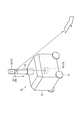
- FIG. 3 is a perspective view of the movable sensor unit 20.
- the movable sensor unit 20 includes four wheels 31, a vehicle body 32, and a detection unit 21.
- the movable sensor unit 20 can travel by driving the wheels 31 by a drive source (not shown).
- the movable sensor unit 20 includes a vehicle control unit.
- the vehicle control unit controls acceleration, deceleration, and steering according to the surrounding environment acquired by the detection unit 21. As a result, the movable sensor unit 20 is capable of automatically traveling.
- the detection unit 21 includes a tubular body 33 that can expand and contract in the vertical direction, and a sensor 34 such as a camera and LiDAR provided inside the tubular body 33.
- a sensor 34 is provided on the top of the tubular body 33.
- the tubular body 33 can rotate around the vertical axis, and the sensor 34 can monitor the situation at a circumference of 360 degrees.
- the movable sensor unit 20 includes a road surface drawing unit 25.
- the road surface drawing unit 25 includes a mirror 35 and a projector device 36.
- the conical mirror 35 is provided below the portion of the tubular body 33 where the sensor 34 is provided.
- the mirror 35 is provided on the tubular body 33 in a posture in which the top thereof is located downward.
- the projector device 36 is provided below the tubular body 33. There is a cavity between the mirror 35 and the projector device 36. The light emitted from the projector device 36 is reflected by the mirror 35, and the light draws a desired image on the road surface.
- the tubular body 33 is configured to be able to expand and contract in the vertical direction by a linear motion device such as a linear guide.
- a linear motion device such as a linear guide.
- the traffic light 40 includes a signal light 41, a wireless communication unit 42, an ID recording unit 43, and an abnormality detection unit 44.
- the signal light 41 controls the passage of surrounding vehicles and pedestrians.
- the abnormality detection unit 44 monitors the failure of the signal light 41.
- the abnormality detection unit 44 detects, for example, a poor continuity of the light source of the signal light 41, or detects a lighting failure of the signal light 41 according to the output of the optical sensor that detects the light of the signal light 41.
- the abnormality detection unit 44 detects the failure of the signal light 41, the abnormality signal is output to the wireless communication unit 42.
- the wireless communication unit 42 transmits the dispatch request signal and the identification information read from the ID recording unit 43 to the command base 10.
- the identification information is information that is assigned to each traffic light 40 and can identify each traffic light 40. In this application example, this identification information corresponds to location information.
- the command unit 13 refers to the signal database and determines the location of the signal 40 in which the abnormality has occurred based on the acquired identification information. Identify.
- the identification information of the traffic light 40 and the location of the traffic light 40 are recorded in association with each other.
- the command unit 13 outputs a command to the sensor unit control unit 11 so that the movable sensor unit 20 moves to the location of the traffic light 40.
- the sensor unit control unit 11 transmits the location of the traffic light 40 to the movable sensor unit 20 and starts the movement.
- the movable sensor unit 20 that received the movement command from the command base 10 automatically travels to the location of the traffic light 40.
- the movable sensor unit 20 monitors the surrounding traffic conditions by using a detection unit 21 such as a camera or LiDAR.
- the traffic information acquired by the detection unit 21 of the movable sensor unit 20 may be transmitted to surrounding vehicles.
- the vehicle traveling in the automatic driving mode can travel based on the camera image and the LiDAR output acquired by the movable sensor unit 20.
- the traffic information acquired by the detection unit 21 of the movable sensor unit 20 may be transmitted to the command base 10. Based on the traffic information received at the command base 10, police officers may be dispatched to the dispatched place if it is determined that traffic control is necessary, such as traffic congestion at the dispatched place.
- the command unit 13 may automatically determine whether or not a police officer needs to be dispatched, or a human may determine.
- the movable sensor unit 20 may control the traffic of surrounding vehicles and pedestrians by using the road surface drawing unit 25 instead of the failed traffic light 40.
- the traveling guide unit 24 controls the road surface drawing unit 25 so as to control the traffic of vehicles and pedestrians based on the output of the detection unit 21.
- the travel guidance unit 24 may output an instruction signal for guiding the travel of the vehicle toward the vehicle capable of inter-vehicle communication.
- the command unit 13 of the command base 10 transmits a command to return to the movable sensor unit 20.
- the wireless communication unit 23 of the movable sensor unit 20 receives the return command, the movable sensor unit 20 automatically returns to the command base 10.
- the movable sensor unit 20 is dispatched to the location of the failed infrastructure equipment Q, resulting in a failure. It is possible to grasp the traffic situation around the infrastructure facility Q. Since the traffic situation around the infrastructure facility Q can be grasped even when the infrastructure facility Q fails, traffic troubles due to the infrastructure failure are unlikely to occur.
- the movable sensor unit 20 includes a detection unit 21 capable of detecting a traffic situation. Therefore, when the infrastructure equipment Q such as the traffic light 40 fails, the sensor information acquired by the movable sensor unit 20 can be transmitted to the surrounding vehicles so as to support the traveling of the vehicle in the automatic driving mode. As a result, it is possible to support the traveling of the vehicle traveling in the automatic driving mode.
- the infrastructure device 50 that requests a vehicle to stop or guides a pedestrian has been proposed.
- the infrastructure device 50 installed at an intersection includes a camera 51, a road surface drawing device 52, a wireless communication unit 53, an ID recording unit 54, and an abnormality detection unit 55.
- Such an infrastructure device 50 grasps the traffic situation of a pedestrian or a vehicle based on an image taken by the camera 51, and instructs the pedestrian or the vehicle to proceed or stop by drawing a road surface.
- the camera 51 detects a pedestrian who wants to cross the pedestrian crossing
- the road surface drawing device 52 draws an image indicating a stop for the vehicle trying to cross the pedestrian crossing.
- an abnormality signal is output to the wireless communication unit 53.
- the wireless communication unit 53 of the infrastructure device 50 to which the abnormal signal is input transmits the dispatch request signal and the identification information read from the ID recording unit 54 to the command base 10.
- the identification information is information that is assigned to each infrastructure device 50 and can identify each infrastructure device 50. In this application example, this identification information corresponds to a location signal.
- the command unit 13 refers to the infrastructure database and refers to the infrastructure device 50 in which an abnormality has occurred based on the acquired identification information. Identify the location.
- the identification information of the infrastructure device 50 and the location of the infrastructure device 50 are recorded in association with each other.
- the command unit 13 outputs a command to the sensor unit control unit 11 so that the movable sensor unit 20 moves to the location of the infrastructure device 50.
- the sensor unit control unit 11 transmits the location of the infrastructure device 50 to the movable sensor unit 20 and starts the movement.
- the movable sensor unit 20 that received the movement command from the command base 10 automatically travels to the location of the infrastructure device 50.
- the detection unit 21 monitors the surrounding traffic conditions, and the road surface drawing device 52 controls the traffic of surrounding vehicles and pedestrians.
- the movable sensor unit 20 may output an instruction signal for guiding the traveling of the vehicle toward the vehicle capable of inter-vehicle communication.
- the command unit 13 of the command base 10 transmits a command to return to the movable sensor unit 20.
- the wireless communication unit 23 of the movable sensor unit 20 receives the return command, the movable sensor unit 20 automatically returns to the command base 10.
- the movable sensor unit 20 when the infrastructure device 50 fails, the movable sensor unit 20 is dispatched to the location of the failed infrastructure device 50, so that the failed infrastructure device 50 You can grasp the traffic situation around.
- the detection unit 21 of the movable sensor unit 20 can substitute the sensing function of the infrastructure device 50.
- the movable sensor unit 20 provided with the traveling guide unit 24 can take over the traffic control function of the infrastructure device 50.
- the movable sensor unit 20 includes a detection unit 21 for detecting a traffic situation. Therefore, when the infrastructure device 50 breaks down, the traffic condition detected by the movable sensor unit 20 can be transmitted to surrounding vehicles to support the traveling of the vehicle traveling in the automatic driving mode.
- the command base 10 may be configured to acquire a dispatch request signal from a vehicle such as a police car P that can monitor the traffic situation.
- the police car P is equipped with a dispatch request device 60 capable of transmitting a dispatch request signal.
- the dispatch request device 60 wirelessly transmits GPS information and a dispatch request signal from a GPS device 61 that identifies its own current position, a wireless communication unit 62 that wirelessly transmits GPS information and a dispatch request signal, and a wireless communication unit 62.
- the switch 63 for transmitting the signal is provided.
- the wireless communication unit 62 transmits the position information (location signal) indicating the current position of the police car P acquired from the GPS device 61 and the dispatch request signal to the command base 10.
- the command unit 13 determines the sensor unit so that the movable sensor unit 20 moves to the location of the police car P indicated by the position information.
- a command is output to the control unit 11.
- the sensor unit control unit 11 transmits position information indicating the current position of the police car P to the movable sensor unit 20 and starts the movement.
- the movable sensor unit 20 that received the movement command from the command base 10 automatically travels to the location of the police car P.
- the movable sensor unit 20 monitors the surrounding traffic conditions by using the detection unit 21.
- the traveling guide unit 24 of the movable sensor unit 20 may use the road surface drawing unit 25 to draw on the road surface to guide pedestrians and vehicles to control traffic.
- the travel guidance unit 24 may output an instruction signal for guiding the travel of the vehicle toward the vehicle capable of inter-vehicle communication.
- the police officer may send a return request signal to the command base 10 via the dispatch request device 60.
- the command unit 13 of the command base 10 transmits a command to return to the command base 10 to the movable sensor unit 20.
- the wireless communication unit 62 of the movable sensor unit 20 receives the return command, the movable sensor unit 20 automatically returns to the command base 10.
- the movable sensor unit 20 is dispatched to a congested point when it becomes necessary to monitor the traffic condition in the case of temporary congestion or the like. Therefore, it is possible to grasp the traffic situation in a congested area. Further, if the movable sensor unit 20 is provided with the road surface drawing unit 25, it is possible to control traffic when the dispatch destination is crowded.
- the movable sensor unit 20 is dispatched to an arbitrary place as needed. Therefore, it is possible to monitor the traffic situation in such a place without installing the infrastructure equipment Q in a place where the traffic volume is normally low but the traffic volume temporarily increases.
- a traffic system suitable for an autonomous driving society and a movable sensor unit used therein are provided.
Landscapes
- Physics & Mathematics (AREA)
- General Physics & Mathematics (AREA)
- Traffic Control Systems (AREA)
Abstract
交通用システム(1)は、交通状況を検出可能な検出部(21)と、移動ユニット(22)と、を備えた可動式センサユニット(20)を制御するセンサユニット制御部(11)と、出動要請信号と、可動式センサユニット(20)を出動させたい場所を示す場所信号と、を取得可能な要請受信部(12)と、出動要請信号を取得した場合に、可動式センサユニット(20)が、場所信号が示す場所へ移動するようにセンサユニット制御部(11)へ指令を送信する指令部(13)と、を含んでいる。
Description
本発明は、交通用システムおよびそれに用いられる可動式センサユニットに関する。
特許文献1は、交差点等に設置された歩行者用の信号機の切替情報を用いて、道路付近に所定の画像を投影することにより、交通違反を抑止する違反抑止システムを開示している。
ところで、慢性的に交通量が多い場所には信号機などのインフラ設備が設置される。しかし、通常時は交通量が少ない場所には一次的に交通量が増加する場合であってもインフラ設備が設置されないことが多い。自動運転モードで走行する車両が増えると、このように一次的に交通量が増加する場所には、交通量の増加時に車両の自動運転モードでの走行を支援する機能を備えたインフラ設備が設置されることが好ましい。しかしながら、常時交通量が多いわけではないので、設置がためらわれる。
また、信号機などの交通インフラが故障した場合には、やはり車両の自動運転モードでの走行を支援する機能を備えたインフラ設備が一次的に求められる。
本発明は、自動運転社会に適した交通用システムおよびそれに用いられる可動式センサユニットを提供することを目的とする。
また、信号機などの交通インフラが故障した場合には、やはり車両の自動運転モードでの走行を支援する機能を備えたインフラ設備が一次的に求められる。
本発明は、自動運転社会に適した交通用システムおよびそれに用いられる可動式センサユニットを提供することを目的とする。
本発明にかかる交通用システムは、
交通状況を検出可能な検出部と、移動ユニットと、を備えた可動式センサユニットを制御するセンサユニット制御部と、
出動要請信号と、前記可動式センサユニットを出動させたい場所を示す場所信号と、を取得可能な要請受信部と、
前記出動要請信号を取得した場合に、前記可動式センサユニットが、前記場所信号が示す場所へ移動するように前記センサユニット制御部へ指令を送信する指令部と、を備えている。
交通状況を検出可能な検出部と、移動ユニットと、を備えた可動式センサユニットを制御するセンサユニット制御部と、
出動要請信号と、前記可動式センサユニットを出動させたい場所を示す場所信号と、を取得可能な要請受信部と、
前記出動要請信号を取得した場合に、前記可動式センサユニットが、前記場所信号が示す場所へ移動するように前記センサユニット制御部へ指令を送信する指令部と、を備えている。
また、本発明にかかる交通用システムに用いられる可動式センサユニットは、
上記交通用システムのセンサユニット制御部と通信可能な通信部と、
交通状況を検出可能なセンサ側検出部と、移動ユニットと、を備えている。
上記交通用システムのセンサユニット制御部と通信可能な通信部と、
交通状況を検出可能なセンサ側検出部と、移動ユニットと、を備えている。
本発明によれば、自動運転社会に適した交通用システムおよびそれに用いられる可動式センサユニットが提供される。
図1は、本発明の実施形態に係る交通用システム1の概念図である。図2は、本発明の実施形態に係る交通用システム1のブロック図である。図1および図2に示すように、本実施形態に係る交通用システム1は、指令基地10と、可動式センサユニット20とから構成されている。指令基地10は、インフラ設備Q(インフラストラクチャ)や、パトカーPなどと無線通信により接続されている。指令基地10は、インフラ設備QやパトカーPから要請を受けると、可動式センサユニット20を派遣して派遣先の交通状況を監視させる。
以下、詳細に説明する。図2に示すように、指令基地10は、センサユニット制御部11と、要請受信部12と、指令部13を備えている。可動式センサユニット20は、検出部21と、移動ユニット22と、無線通信部23と、走行案内部24と、路面描画部25を備えている。
図3は、可動式センサユニット20の斜視図である。図3に示すように、可動式センサユニット20は、4つの車輪31と、車体32と、検出部21を備えている。可動式センサユニット20は、図示せぬ駆動源により車輪31が駆動され、走行可能である。また、この可動式センサユニット20は車両制御部を備えている。車両制御部は検出部21が取得した周囲の環境に応じて加速・減速・操舵を制御する。これにより、可動式センサユニット20は自動走行可能とされている。
検出部21は、上下方向に伸縮可能な筒状体33と、この筒状体33の内部に設けられたカメラおよびLiDARといったセンサ34を備えている。筒状体33の頂部にセンサ34が設けられている。筒状体33は鉛直軸線回りに回転可能であり、センサ34は周囲360度の状況を監視可能とされている。
可動式センサユニット20は路面描画部25を備えている。路面描画部25は、ミラー35とプロジェクタ装置36とを備えている。円錐状のミラー35は、筒状体33のセンサ34が設けられた部位の下部に設けられている。ミラー35はその頂部が下方に位置する姿勢で筒状体33に設けられている。プロジェクタ装置36は筒状体33の下方に設けられている。ミラー35とプロジェクタ装置36の間は空洞とされている。プロジェクタ装置36から出射された光がミラー35で反射され、この光によって路面に所望の画像が描画される。
筒状体33はリニアガイドなどの直動装置などによって上下方向に伸縮可能に構成されている。必要に応じて筒状体33が伸長し、所望の高さまでセンサ34、ミラー35を持ち上げることで、車両の周囲の情報をより広範囲に取得し、広い範囲に路面描画を行うことができる。
(第一の適用例)
次に、上述した実施形態の交通用システム1の指令基地10が信号機40から出動要請信号を受けた場合を説明する。例えば信号機40に異常が生じた時に、指令基地10は可動式センサユニット20を信号機40の場所に派遣して交通状況を検出させる。
次に、上述した実施形態の交通用システム1の指令基地10が信号機40から出動要請信号を受けた場合を説明する。例えば信号機40に異常が生じた時に、指令基地10は可動式センサユニット20を信号機40の場所に派遣して交通状況を検出させる。
図2に示したように、信号機40は信号灯41と、無線通信部42と、ID記録部43と、異常検出部44を備えている。
信号灯41は、周囲の車両や歩行者の通行を制御している。
異常検出部44は、この信号灯41の故障を監視している。異常検出部44は、例えば信号灯41の光源の導通不良を検出したり、信号灯41の光を検出する光センサの出力に応じて、信号灯41の点灯不良を検出する。異常検出部44が信号灯41の故障を検出すると異常信号を無線通信部42へ出力する。異常信号が入力されると無線通信部42は出動要請信号と、ID記録部43から読み出した識別情報とを、指令基地10に向けて送信する。識別情報とは、各々の信号機40に割り当てられ、各々の信号機40を特定可能な情報である。本適用例においては、この識別情報が場所情報に該当する。
信号灯41は、周囲の車両や歩行者の通行を制御している。
異常検出部44は、この信号灯41の故障を監視している。異常検出部44は、例えば信号灯41の光源の導通不良を検出したり、信号灯41の光を検出する光センサの出力に応じて、信号灯41の点灯不良を検出する。異常検出部44が信号灯41の故障を検出すると異常信号を無線通信部42へ出力する。異常信号が入力されると無線通信部42は出動要請信号と、ID記録部43から読み出した識別情報とを、指令基地10に向けて送信する。識別情報とは、各々の信号機40に割り当てられ、各々の信号機40を特定可能な情報である。本適用例においては、この識別情報が場所情報に該当する。
指令基地10の要請受信部12が信号機40から出動要請信号と識別情報を取得すると、指令部13は、信号機データベースを参照し、取得した識別情報に基づいて異常が生じている信号機40の所在地を特定する。信号機データベースには、信号機40の識別情報と、信号機40の所在地とが関連付けられて記録されている。
指令部13は、可動式センサユニット20が信号機40の所在地へ移動するようにセンサユニット制御部11へ指令を出力する。センサユニット制御部11は、指令部13から可動式センサユニット20を移動させる指令が入力されると、可動式センサユニット20に信号機40の所在地を送信し、移動を開始させる。
指令基地10から移動指令を受信した可動式センサユニット20は信号機40の所在地まで自動走行する。可動式センサユニット20は、信号機40の所在地に到達すると、カメラやLiDARなどの検出部21を使って周囲の交通状況を監視する。可動式センサユニット20の検出部21が取得した交通情報は、周囲の車両に送信してもよい。これにより、自動運転モードで走行する車両は、可動式センサユニット20が取得したカメラ画像やLiDAR出力に基づいて走行することができる。
あるいは、可動式センサユニット20の検出部21が取得した交通情報は、指令基地10に送信されてもよい。指令基地10で受信した交通情報に基づき、派遣地に交通渋滞が生じているなど、交通整理の必要があると判断されれば、警察官を派遣地に派遣してもよい。警察官の派遣の必要性の有無は、指令部13が自動的に判断してもよいし、人間が判断してもよい。
なお、可動式センサユニット20は、故障した信号機40に代わって、路面描画部25を用いて周囲の車両や歩行者の交通を制御してもよい。走行案内部24が、検出部21の出力に基づいて車両や歩行者の交通を制御するように、路面描画部25を制御する。あるいは、走行案内部24は、車車間通信可能な車両に向けて、車両の走行を案内する指示信号を出力してもよい。
故障した信号機40の修理が完了すると、指令基地10の指令部13が可動式センサユニット20に帰還させる指令を送信する。可動式センサユニット20の無線通信部23が帰還指令を受信すると、可動式センサユニット20は指令基地10まで自動運転で帰還する。
このように本実施形態に係る交通用システム1によれば、信号機40などのインフラ設備Qが故障した際などに、可動式センサユニット20が故障したインフラ設備Qの所在地まで派遣されるため、故障したインフラ設備Qの周囲の交通状況を把握できる。インフラ設備Qの故障時にもその周囲の交通状況を把握できるので、インフラ故障に伴う交通トラブルが生じにくい。
本実施形態に係る交通用システム1によれば、可動式センサユニット20が交通状況を検出可能な検出部21を備えている。このため、信号機40などのインフラ設備Qの故障時に、車両の自動運転モードでの走行を支援するように周囲の車両に可動式センサユニット20が取得したセンサ情報を送信することができる。これにより、自動運転モードで走行する車両の走行を支援することができる。
(第二の適用例)
次に、上述した実施形態の交通用システム1が、周囲の車両に対して交通を指示するインフラ装置50が故障した場合に適用される例を説明する。
近年、車両へ停止を求めたり、歩行者を誘導するインフラ装置50が提案されている。例えば、交差点に設置されたインフラ装置50は、図2に示したように、カメラ51、路面描画装置52、無線通信部53、ID記録部54、異常検出部55を備えている。このようなインフラ装置50は、カメラ51で撮影した画像に基づいて歩行者や車両の交通状況を把握し、歩行者や車両へ路面描画によって進行や停止を指示する。例えば、カメラ51によって横断歩道を渡りたい歩行者を検出した際は、路面描画装置52が横断歩道を横切ろうとする車両に対して停止を示す画像を描画する。
次に、上述した実施形態の交通用システム1が、周囲の車両に対して交通を指示するインフラ装置50が故障した場合に適用される例を説明する。
近年、車両へ停止を求めたり、歩行者を誘導するインフラ装置50が提案されている。例えば、交差点に設置されたインフラ装置50は、図2に示したように、カメラ51、路面描画装置52、無線通信部53、ID記録部54、異常検出部55を備えている。このようなインフラ装置50は、カメラ51で撮影した画像に基づいて歩行者や車両の交通状況を把握し、歩行者や車両へ路面描画によって進行や停止を指示する。例えば、カメラ51によって横断歩道を渡りたい歩行者を検出した際は、路面描画装置52が横断歩道を横切ろうとする車両に対して停止を示す画像を描画する。
このようなインフラ装置50において、異常検出部55がカメラ51や路面描画装置52の故障を検出したとき、無線通信部53へ異常信号を出力する。異常信号が入力されたインフラ装置50の無線通信部53は、出動要請信号と、ID記録部54から読み出した識別情報とを、指令基地10に向けて送信する。識別情報とは、各々のインフラ装置50に割り当てられ、各々のインフラ装置50を特定可能な情報である。本適用例においては、この識別情報が場所信号に該当する。
指令基地10の要請受信部12がインフラ装置50から出動要請信号と識別情報を取得すると、指令部13は、インフラデータベースを参照し、取得した識別情報に基づいて異常が生じているインフラ装置50の所在地を特定する。インフラデータベースには、インフラ装置50の識別情報と、インフラ装置50の所在地とが関連付けられて記録されている。
指令部13は、可動式センサユニット20がインフラ装置50の所在地へ移動するようにセンサユニット制御部11へ指令を出力する。センサユニット制御部11は、指令部13から可動式センサユニット20を移動させる指令が入力されると、可動式センサユニット20にインフラ装置50の所在地を送信し、移動を開始させる。
指令基地10から移動指令を受信した可動式センサユニット20はインフラ装置50の所在地まで自動走行する。可動式センサユニット20は、インフラ装置50の所在地に到達すると、検出部21を使って周囲の交通状況を監視し、路面描画装置52を用いて周囲の車両や歩行者の交通を制御する。あるいは、可動式センサユニット20は、車車間通信可能な車両に向けて、車両の走行を案内する指示信号を出力してもよい。
故障したインフラ装置50の修理が完了すると、指令基地10の指令部13が可動式センサユニット20に帰還させる指令を送信する。可動式センサユニット20の無線通信部23が帰還指令を受信すると、可動式センサユニット20は指令基地10まで自動運転で帰還する。
このように本実施形態に係る交通用システム1によれば、インフラ装置50が故障した際などに、可動式センサユニット20が故障したインフラ装置50の所在地まで派遣されるため、故障したインフラ装置50の周囲の交通状況を把握できる。周囲の交通状況を検出するセンサ(カメラ51)を備えているインフラ装置50が故障した場合、可動式センサユニット20の検出部21により、インフラ装置50のセンシング機能を代行することができる。さらに周囲の交通を制御する機能を備えているインフラ装置50が故障した場合、走行案内部24を備えた可動式センサユニット20はインフラ装置50の交通制御機能を代行することができる。
本実施形態に係る可動式センサユニット20は交通状況を検出する検出部21を備えている。このため、インフラ装置50が故障した時に、可動式センサユニット20が検出した交通状況を周囲の車両に送信し、自動運転モードで走行する車両の走行を支援することができる。
(第三適用例)
上述した第一の適用例および第二の適用例においては、インフラ設備Qから指令基地10に出動要請信号が送信される例を説明したが、本発明はこの例に限られない。
指令基地10は、パトカーPなどの交通状況を監視できる車両から出動要請信号を取得するように構成してもよい。この場合、パトカーPには出動要請信号を送信可能な出動要請装置60が搭載される。出動要請装置60は、自身の現在位置を特定するGPS装置61と、GPS情報と出動要請信号とを無線で送信する無線通信部62と、無線通信部62からGPS情報と出動要請信号とを無線を送信させるスイッチ63を備えている。
上述した第一の適用例および第二の適用例においては、インフラ設備Qから指令基地10に出動要請信号が送信される例を説明したが、本発明はこの例に限られない。
指令基地10は、パトカーPなどの交通状況を監視できる車両から出動要請信号を取得するように構成してもよい。この場合、パトカーPには出動要請信号を送信可能な出動要請装置60が搭載される。出動要請装置60は、自身の現在位置を特定するGPS装置61と、GPS情報と出動要請信号とを無線で送信する無線通信部62と、無線通信部62からGPS情報と出動要請信号とを無線を送信させるスイッチ63を備えている。
パトカーPに搭乗しパトロールしている警察官が、コンサートや祭りなどで一時的に多くの人が集中している地域を発見したときに、出動要請装置60のスイッチ63を操作する。これにより、無線通信部62は、GPS装置61から取得したパトカーPの現在位置を示す位置情報(場所信号)と、出動要請信号とを、指令基地10へ送信する。
指令基地10の要請受信部12が出動要請装置60から出動要請信号と位置情報を取得すると、指令部13は、位置情報が示すパトカーPの所在地へ可動式センサユニット20が移動するようにセンサユニット制御部11へ指令を出力する。センサユニット制御部11は、指令部13から可動式センサユニット20を移動させる指令が入力されると、可動式センサユニット20にパトカーPの現在位置を示す位置情報を送信し、移動を開始させる。
指令基地10から移動指令を受信した可動式センサユニット20はパトカーPの所在地まで自動走行する。可動式センサユニット20は、パトカーPの所在地に到達すると、検出部21を使って周囲の交通状況を監視する。また、可動式センサユニット20の走行案内部24は、路面描画部25を使って路面に描画を行って歩行者や車両を誘導し、交通整理を行ってもよい。あるいは、走行案内部24は、車車間通信可能な車両に向けて、車両の走行を案内する指示信号を出力してもよい。
警察官は、イベントが終了して混雑が解消し交通状況を監視する必要が無くなったと判断したら、出動要請装置60を介して指令基地10へ帰還要請信号を送信してもよい。指令基地10の指令部13は、帰還要請信号を取得したら、可動式センサユニット20に指令基地10まで帰還させる指令を送信する。可動式センサユニット20の無線通信部62が帰還指令を受信すると、可動式センサユニット20は指令基地10まで自動運転で帰還する。
このように本実施形態に係る交通用システム1によれば、一時的に混雑が生じた場合などで交通状況を監視する必要が生じた場合に、可動式センサユニット20が混雑した地点に派遣されるため、混雑地の交通状況を把握できる。また、可動式センサユニット20が路面描画部25を備えていれば、派遣先の混雑時に交通整理を行うことができる。
本実施形態に係る交通用システム1によれば、必要に応じて可動式センサユニット20が任意の場所に派遣される。このため、通常時は交通量が少ないが一時的に交通量が増大する場所にインフラ設備Qを設置しなくても、このような場所の交通状況を監視することができる。
本出願は、2019年6月13日出願の日本特許出願(特願2019-110191)に基づくものであり、その内容はここに参照として取り込まれる。
本発明によれば、自動運転社会に適した交通用システムおよびそれに用いられる可動式センサユニットが提供される。
1 交通用システム
10 指令基地
11 センサユニット制御部
12 要請受信部
13 指令部
20 可動式センサユニット
21 検出部
22 移動ユニット
23 無線通信部
24 走行案内部
25 路面描画部
31 車輪
32 車体
33 筒状体
34 センサ
35 ミラー
36 プロジェクタ装置
40 信号機
41 信号灯
42 無線通信部
43 ID記録部
44 異常検出部
50 インフラ装置
51 カメラ
52 路面描画装置
53 無線通信部
54 ID記録部
55 異常検出部
60 出動要請装置
61 GPS装置
62 無線通信部
63 スイッチ
P パトカー
Q インフラ設備
10 指令基地
11 センサユニット制御部
12 要請受信部
13 指令部
20 可動式センサユニット
21 検出部
22 移動ユニット
23 無線通信部
24 走行案内部
25 路面描画部
31 車輪
32 車体
33 筒状体
34 センサ
35 ミラー
36 プロジェクタ装置
40 信号機
41 信号灯
42 無線通信部
43 ID記録部
44 異常検出部
50 インフラ装置
51 カメラ
52 路面描画装置
53 無線通信部
54 ID記録部
55 異常検出部
60 出動要請装置
61 GPS装置
62 無線通信部
63 スイッチ
P パトカー
Q インフラ設備
Claims (5)
- 交通状況を検出可能な検出部と、移動ユニットと、を備えた可動式センサユニットを制御するセンサユニット制御部と、
出動要請信号と、前記可動式センサユニットを出動させたい場所を示す場所信号と、を取得可能な要請受信部と、
前記出動要請信号を取得した場合に、前記可動式センサユニットが、前記場所信号が示す場所へ移動するように前記センサユニット制御部へ指令を送信する指令部と、
を備えた、交通用システム。 - 前記要請受信部は、交通用インフラの異常時に出力される異常信号を前記出動要請信号として取得し、かつ前記交通用インフラの識別情報を前記場所信号として取得し、
前記交通用インフラの識別情報と前記交通用インフラの場所情報を含むデータベースと、取得した前記場所信号と、に基づいて、前記可動式センサユニットを移動させる場所を特定する、請求項1に記載の交通用システム。 - 前記要請受信部は、前記出動要請信号を出力可能でかつ自身の位置を示す前記場所信号を出力可能な出動要請装置から、前記出動要請信号と前記場所信号と、を取得する、請求項1に記載の交通用システム。
- 請求項1に記載の前記交通用システムの前記センサユニット制御部と通信可能な通信部と、
交通状況を検出可能なセンサ側検出部と、移動ユニットと、を備えた可動式センサユニット。 - 前記センサユニット制御部は、前記センサ側検出部の検出結果に基づいて、車両の走行を案内する指示信号を出力する、請求項4に記載の可動式センサユニット。
Priority Applications (1)
| Application Number | Priority Date | Filing Date | Title |
|---|---|---|---|
| JP2021525968A JPWO2020250644A1 (ja) | 2019-06-13 | 2020-05-22 |
Applications Claiming Priority (2)
| Application Number | Priority Date | Filing Date | Title |
|---|---|---|---|
| JP2019110191 | 2019-06-13 | ||
| JP2019-110191 | 2019-06-13 |
Publications (1)
| Publication Number | Publication Date |
|---|---|
| WO2020250644A1 true WO2020250644A1 (ja) | 2020-12-17 |
Family
ID=73781814
Family Applications (1)
| Application Number | Title | Priority Date | Filing Date |
|---|---|---|---|
| PCT/JP2020/020340 Ceased WO2020250644A1 (ja) | 2019-06-13 | 2020-05-22 | 交通用システムおよびそれに用いられる可動式センサユニット |
Country Status (2)
| Country | Link |
|---|---|
| JP (1) | JPWO2020250644A1 (ja) |
| WO (1) | WO2020250644A1 (ja) |
Citations (3)
| Publication number | Priority date | Publication date | Assignee | Title |
|---|---|---|---|---|
| JP2007102488A (ja) * | 2005-10-04 | 2007-04-19 | Toyota Motor Corp | 自律移動装置 |
| JP2009037623A (ja) * | 2007-08-03 | 2009-02-19 | Korea Electronics Telecommun | 交通統制ロボットとこれを用いた交通統制システム及びその制御方法 |
| JP2020091854A (ja) * | 2018-11-22 | 2020-06-11 | 株式会社Vollmontホールディングス | 歩行者誘導システム及び歩行者誘導ロボット |
-
2020
- 2020-05-22 WO PCT/JP2020/020340 patent/WO2020250644A1/ja not_active Ceased
- 2020-05-22 JP JP2021525968A patent/JPWO2020250644A1/ja active Pending
Patent Citations (3)
| Publication number | Priority date | Publication date | Assignee | Title |
|---|---|---|---|---|
| JP2007102488A (ja) * | 2005-10-04 | 2007-04-19 | Toyota Motor Corp | 自律移動装置 |
| JP2009037623A (ja) * | 2007-08-03 | 2009-02-19 | Korea Electronics Telecommun | 交通統制ロボットとこれを用いた交通統制システム及びその制御方法 |
| JP2020091854A (ja) * | 2018-11-22 | 2020-06-11 | 株式会社Vollmontホールディングス | 歩行者誘導システム及び歩行者誘導ロボット |
Also Published As
| Publication number | Publication date |
|---|---|
| JPWO2020250644A1 (ja) | 2020-12-17 |
Similar Documents
| Publication | Publication Date | Title |
|---|---|---|
| US9829889B1 (en) | Autonomous vehicle advanced notification system and method of use | |
| US20200207338A1 (en) | System, Method, Infrastructure, and Vehicle for Automated Valet Parking | |
| JP6413962B2 (ja) | 走行制御装置 | |
| CN112349090A (zh) | 车辆远程指示系统以及远程指示装置 | |
| KR20190088135A (ko) | 자율주행 화물차량 관제 시스템 및 방법 | |
| JP2017097519A (ja) | 自動運転支援装置、自動運転支援システム、自動運転支援方法、プログラムおよび記録媒体 | |
| CN110691956B (zh) | 车辆控制装置 | |
| US11669095B2 (en) | Method for the driverless operation of a vehicle | |
| US20230211774A1 (en) | Method for controlling an automated parking system and automated parking system | |
| JP2020194209A (ja) | 制御装置、乗降施設、制御方法、およびプログラム | |
| CN108630003A (zh) | 自动化车辆安全停车区域使用通知系统 | |
| JP7147858B2 (ja) | 車両の走行制御方法及び走行制御装置 | |
| JP2006151014A (ja) | 安全運転支援システム | |
| JP2021046182A (ja) | 自動運転車 | |
| KR20180134661A (ko) | 가시광 통신을 이용한 무인반송차 제어시스템 | |
| JP2006298041A (ja) | 車両の運転支援システム | |
| JP6776535B2 (ja) | 車両制御装置 | |
| JP2009037462A (ja) | 交通情報提供システムおよび交通情報提供方法 | |
| WO2020250644A1 (ja) | 交通用システムおよびそれに用いられる可動式センサユニット | |
| JP2023151299A (ja) | 管制システム | |
| JP2021062768A (ja) | 自動運転車 | |
| KR20130033589A (ko) | 승강장 안전선 및 선로 감시 시스템 | |
| KR101734997B1 (ko) | 차로간 원격 신호제어시스템 및 방법 | |
| JP2019106098A (ja) | 無人駐車システム | |
| JP7286914B2 (ja) | 自動駐車場装置、自動駐車場システム、自動駐車場管理方法及びそのプログラム |
Legal Events
| Date | Code | Title | Description |
|---|---|---|---|
| 121 | Ep: the epo has been informed by wipo that ep was designated in this application |
Ref document number: 20823478 Country of ref document: EP Kind code of ref document: A1 |
|
| ENP | Entry into the national phase |
Ref document number: 2021525968 Country of ref document: JP Kind code of ref document: A |
|
| NENP | Non-entry into the national phase |
Ref country code: DE |
|
| 122 | Ep: pct application non-entry in european phase |
Ref document number: 20823478 Country of ref document: EP Kind code of ref document: A1 |