WO2020250515A1 - 制御装置および操作システム - Google Patents
制御装置および操作システム Download PDFInfo
- Publication number
- WO2020250515A1 WO2020250515A1 PCT/JP2020/010565 JP2020010565W WO2020250515A1 WO 2020250515 A1 WO2020250515 A1 WO 2020250515A1 JP 2020010565 W JP2020010565 W JP 2020010565W WO 2020250515 A1 WO2020250515 A1 WO 2020250515A1
- Authority
- WO
- WIPO (PCT)
- Prior art keywords
- operating member
- control device
- joint
- rotation angle
- detection signal
- Prior art date
- Legal status (The legal status is an assumption and is not a legal conclusion. Google has not performed a legal analysis and makes no representation as to the accuracy of the status listed.)
- Ceased
Links
Images


Classifications
-
- A—HUMAN NECESSITIES
- A63—SPORTS; GAMES; AMUSEMENTS
- A63F—CARD, BOARD, OR ROULETTE GAMES; INDOOR GAMES USING SMALL MOVING PLAYING BODIES; VIDEO GAMES; GAMES NOT OTHERWISE PROVIDED FOR
- A63F13/00—Video games, i.e. games using an electronically generated display having two or more dimensions
- A63F13/20—Input arrangements for video game devices
- A63F13/24—Constructional details thereof, e.g. game controllers with detachable joystick handles
-
- A—HUMAN NECESSITIES
- A63—SPORTS; GAMES; AMUSEMENTS
- A63F—CARD, BOARD, OR ROULETTE GAMES; INDOOR GAMES USING SMALL MOVING PLAYING BODIES; VIDEO GAMES; GAMES NOT OTHERWISE PROVIDED FOR
- A63F13/00—Video games, i.e. games using an electronically generated display having two or more dimensions
- A63F13/20—Input arrangements for video game devices
- A63F13/21—Input arrangements for video game devices characterised by their sensors, purposes or types
- A63F13/218—Input arrangements for video game devices characterised by their sensors, purposes or types using pressure sensors, e.g. generating a signal proportional to the pressure applied by the player
-
- G—PHYSICS
- G05—CONTROLLING; REGULATING
- G05G—CONTROL DEVICES OR SYSTEMS INSOFAR AS CHARACTERISED BY MECHANICAL FEATURES ONLY
- G05G1/00—Controlling members, e.g. knobs or handles; Assemblies or arrangements thereof; Indicating position of controlling members
- G05G1/015—Arrangements for indicating the position of a controlling member
-
- G—PHYSICS
- G05—CONTROLLING; REGULATING
- G05G—CONTROL DEVICES OR SYSTEMS INSOFAR AS CHARACTERISED BY MECHANICAL FEATURES ONLY
- G05G5/00—Means for preventing, limiting or returning the movements of parts of a control mechanism, e.g. locking controlling member
- G05G5/05—Means for returning or tending to return controlling members to an inoperative or neutral position, e.g. by providing return springs or resilient end-stops
-
- G—PHYSICS
- G05—CONTROLLING; REGULATING
- G05G—CONTROL DEVICES OR SYSTEMS INSOFAR AS CHARACTERISED BY MECHANICAL FEATURES ONLY
- G05G5/00—Means for preventing, limiting or returning the movements of parts of a control mechanism, e.g. locking controlling member
- G05G5/06—Means for preventing, limiting or returning the movements of parts of a control mechanism, e.g. locking controlling member for holding members in one or a limited number of definite positions only
-
- A—HUMAN NECESSITIES
- A63—SPORTS; GAMES; AMUSEMENTS
- A63F—CARD, BOARD, OR ROULETTE GAMES; INDOOR GAMES USING SMALL MOVING PLAYING BODIES; VIDEO GAMES; GAMES NOT OTHERWISE PROVIDED FOR
- A63F2300/00—Features of games using an electronically generated display having two or more dimensions, e.g. on a television screen, showing representations related to the game
- A63F2300/10—Features of games using an electronically generated display having two or more dimensions, e.g. on a television screen, showing representations related to the game characterized by input arrangements for converting player-generated signals into game device control signals
- A63F2300/1043—Features of games using an electronically generated display having two or more dimensions, e.g. on a television screen, showing representations related to the game characterized by input arrangements for converting player-generated signals into game device control signals being characterized by constructional details
-
- F—MECHANICAL ENGINEERING; LIGHTING; HEATING; WEAPONS; BLASTING
- F16—ENGINEERING ELEMENTS AND UNITS; GENERAL MEASURES FOR PRODUCING AND MAINTAINING EFFECTIVE FUNCTIONING OF MACHINES OR INSTALLATIONS; THERMAL INSULATION IN GENERAL
- F16H—GEARING
- F16H19/00—Gearings comprising essentially only toothed gears or friction members and not capable of conveying indefinitely-continuing rotary motion
- F16H19/02—Gearings comprising essentially only toothed gears or friction members and not capable of conveying indefinitely-continuing rotary motion for interconverting rotary or oscillating motion and reciprocating motion
- F16H19/04—Gearings comprising essentially only toothed gears or friction members and not capable of conveying indefinitely-continuing rotary motion for interconverting rotary or oscillating motion and reciprocating motion comprising a rack
- F16H2019/046—Facilitating the engagement or stopping of racks
-
- G—PHYSICS
- G05—CONTROLLING; REGULATING
- G05G—CONTROL DEVICES OR SYSTEMS INSOFAR AS CHARACTERISED BY MECHANICAL FEATURES ONLY
- G05G1/00—Controlling members, e.g. knobs or handles; Assemblies or arrangements thereof; Indicating position of controlling members
- G05G1/02—Controlling members for hand actuation by linear movement, e.g. push buttons
-
- H—ELECTRICITY
- H01—ELECTRIC ELEMENTS
- H01H—ELECTRIC SWITCHES; RELAYS; SELECTORS; EMERGENCY PROTECTIVE DEVICES
- H01H13/00—Switches having rectilinearly-movable operating part or parts adapted for pushing or pulling in one direction only, e.g. push-button switch
- H01H13/02—Details
- H01H13/12—Movable parts; Contacts mounted thereon
- H01H13/20—Driving mechanisms
-
- H—ELECTRICITY
- H01—ELECTRIC ELEMENTS
- H01H—ELECTRIC SWITCHES; RELAYS; SELECTORS; EMERGENCY PROTECTIVE DEVICES
- H01H3/00—Mechanisms for operating contacts
- H01H2003/008—Mechanisms for operating contacts with a haptic or a tactile feedback controlled by electrical means, e.g. a motor or magnetofriction
-
- H—ELECTRICITY
- H01—ELECTRIC ELEMENTS
- H01H—ELECTRIC SWITCHES; RELAYS; SELECTORS; EMERGENCY PROTECTIVE DEVICES
- H01H3/00—Mechanisms for operating contacts
- H01H3/32—Driving mechanisms, i.e. for transmitting driving force to the contacts
- H01H3/40—Driving mechanisms, i.e. for transmitting driving force to the contacts using friction, toothed, or screw-and-nut gearing
Definitions
- the present invention relates to a control device and an operation system.
- an operation member that can be pushed by an operator and an operation member are urged to initially perform an operation member when the push operation of the operation member is released.
- an urging means for example, a coil spring or the like
- Patent Document 1 in a game controller provided with an operation unit that can be pushed in, a motor that applies a force to the operation unit is provided, and the operation of the motor is controlled.
- a technique that makes it possible to limit the amount of movement of the operation unit is disclosed.
- the control device of one embodiment is a control device that controls the operation device, and the operation device includes an operation member that can be pushed and operated by the operator, an urging means that urges the operation member in the return direction, and an operation member.
- the control device has a detection means that detects the movement amount of the vehicle and outputs a detection signal indicating the movement amount, and a braking means that brakes the movement of the operation member.
- the control device has the operation member based on the detection signal. When it is detected that the operating member has been pushed to a predetermined pushing position, the braking means holds the pushed state of the operating member, and based on the detection signal, the clearance existing in the drive transmission system between the operating member and the braking means. When it is detected that the operating member has moved in the returning direction, the holding operation by the braking means is released.
- External perspective view of the operating device External perspective view of the operating device according to one embodiment External perspective view of the operating device according to one embodiment External perspective view of the operating device according to one embodiment Left side view of the operating device according to one embodiment External perspective view of the connecting mechanism according to one embodiment An exploded perspective view of the connecting mechanism according to the embodiment.
- a perspective sectional view of a connecting mechanism according to an embodiment. A block diagram showing a system configuration of an operation system according to an embodiment A flowchart showing a processing procedure by the control device according to the embodiment. The figure for demonstrating the operation of the operation apparatus which concerns on one Embodiment A graph showing an example of control by the control device according to one embodiment.
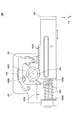
- FIG. 1 to 3 are external perspective views of the operating device 100 according to the embodiment.
- FIG. 2 shows the operating device 100 in a state where the frame 101 is removed.
- FIG. 3 shows the bottom surface side (Z-axis negative side) of the operating device 100 shown in FIG.
- FIG. 4 is a left side view of the operation device 100 according to the embodiment.
- FIG. 4 shows the operating device 100 in a state where the frame 101, the substrate 105, and the rotation angle detection sensor 106 are removed.
- the X-axis direction in the figure is the front-back direction
- the Y-axis direction in the figure is the left-right direction
- the Z-axis direction in the figure is the up-down direction.
- the positive direction of the X-axis is the front
- the positive direction of the Y-axis is the right
- the positive direction of the Z-axis is the top.
- the operating device 100 includes a frame 101, a gearbox 102, an operating member 103, a compression coil spring 104, a substrate 105, a rotation angle detection sensor 106, a brake mechanism 107, and a connecting mechanism 110. There is.
- the frame 101 is a member that supports each component.
- the frame 101 supports the substrate 105 and the rotation angle detection sensor 106 arranged on the left side (Y-axis negative side) of the frame 101.
- the frame 101 supports a gearbox 102 arranged on the right side (Y-axis positive side) of the frame 101.
- the gear box 102 has a space 102A, a front wall surface 102B, a gear 102C, and a pinion shaft 102D.
- a gear 102C, a pinion shaft 102D, an operating member 103, and a compression coil spring 104 are arranged inside the space 102A.
- the gear 102C and the pinion shaft 102D are examples of the "rotating member", and are rotatably provided around the axis of the rotating shaft AX (see FIG. 4) parallel to the Y axis inside the space 102A.
- the gear 102C is provided coaxially with the pinion shaft 102D and is fixed to the pinion shaft 102D. As a result, the gear 102C rotates together with the pinion shaft 102D.
- the front wall surface 102B is a wall surface exposed to the space 102A, and is a wall surface facing the front end surface 103B of the operating member 103.
- the operating member 103 is slidably provided in the front-rear direction (X-axis direction in the drawing) in the space 102A formed in the gear box 102.
- the operating member 103 is a member having a substantially square columnar shape (but not limited to this) extending in the front-rear direction (X-axis direction in the drawing).
- the operating member 103 can be moved forward (in the positive direction of the X-axis) in the space 102A of the gearbox 102 by a pushing operation by the operator.
- a rack gear 103A in which a plurality of teeth are arranged in the front-rear direction is formed on the upper surface of the operating member 103.
- the rack gear 103A meshes with the gear 102C provided in the space 102A of the gear box 102, and constitutes the rack and pinion mechanism with the gear 102C.
- the operating member 103 can rotate the gear 102C via the rack and pinion mechanism as it moves in the front-rear direction (X-axis direction in the drawing).
- the compression coil spring 104 is an example of the "urging means".
- the compression coil spring 104 is provided so as to be elastically deformed in the front-rear direction (X-axis direction in the drawing) between the front end surface 103B of the operating member 103 and the front wall surface 102B of the gearbox 102.
- the compression coil spring 104 urges the operating member 103 rearward (in the negative direction of the X-axis in the drawing). As a result, the operating member 103 can automatically return to the rear when it is released from the pushing operation.
- the substrate 105 is a flat plate-shaped member on which various electric components (for example, rotation angle detection sensor 106, etc.) are mounted.
- the substrate 105 is provided on the rotation axis AX and is fixed to the left side (Y-axis negative side) of the frame 101.
- a rigid substrate such as PWB (Printed Wiring Board) is used.
- the rotation angle detection sensor 106 is an example of "detection means".
- the rotation angle detection sensor 106 is provided on the rotation shaft AX, and detects the rotation angles of the gear 102C and the pinion shaft 102D.
- the rotation angle detection sensor 106 is mounted on the surface of the substrate 105 (the surface on the negative side of the Y-axis).
- the rotation angle detection sensor 106 has a case 106a and a rotor portion 106b.
- the case 106a is fixed to the surface of the substrate 105 (the surface on the negative side of the Y-axis) and accommodates the rotor portion 106b.
- the rotor portion 106b is rotatably provided inside the case 106a.
- the rotor portion 106b is fitted with the tip portion of the pinion shaft 102D penetrating the substrate 105. As a result, the rotor portion 106b rotates together with the gear 102C and the pinion shaft 102D as the operating member 103 is pushed in.
- the rotation angle detection sensor 106 detects the rotation angle
- the rotation angle detection sensor 106 outputs a rotation angle detection signal indicating the rotation angle to the control device 120.
- the rotation angle detected by the rotation angle detection sensor 106 is proportional to the pushing amount of the operating member 103. Therefore, the control device 120 can convert the rotation angle detected by the rotation angle detection sensor 106 into the pushing amount of the operating member 103 by a predetermined conversion formula.
- rotation angle detection sensor 106 a resistance type, magnetic type, optical type, mechanical type or the like can be used. Further, instead of the rotation angle detection sensor 106, a linear position sensor that directly detects the pushing amount of the operating member 202 (that is, the moving amount of the operating member 103 in the front-rear direction) may be used.
- the brake mechanism 107 is an example of "braking means".
- the brake mechanism 107 is provided on the rotating shaft AX and is connected to the pinion shaft 102D via the connecting mechanism 110.
- the brake mechanism 107 operates in response to a control signal supplied from the outside to brake the rotation of the gear 102C and the pinion shaft 102D.
- a so-called electromagnetic brake is used as the brake mechanism 107.
- the connecting mechanism 110 is provided on the rotating shaft AX and between the pinion shaft 102D and the brake mechanism 107.
- the connecting mechanism 110 connects the brake mechanism 107 to the pinion shaft 102D.
- a so-called coupling joint is used as the connecting mechanism 110.
- the electrical connection configuration (for example, flexible wiring board, etc.) of the operating device 100 with the outside is not shown.
- the operating device 100 has at least an electrical connection configuration for supplying a control signal to the brake mechanism 107 from the outside and an electrical connection for outputting the rotation angle detection signal from the rotation angle detection sensor 106 to the outside. It has a connection configuration.
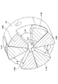
- FIG. 5 is an external perspective view of the connecting mechanism 110 according to the embodiment.
- FIG. 6 is an exploded perspective view of the connecting mechanism 110 according to the embodiment.
- FIG. 7 is a perspective sectional view of the connecting mechanism 110 according to the embodiment.
- the connecting mechanism 110 has a first joint 111 and a second joint 112.
- the first joint 111 is attached to the tip of the pinion shaft 102D and rotates together with the pinion shaft 102D.
- the first joint 111 has three claws 111B protruding toward the second joint 112 on the surface 111A facing the second joint 112.
- the three claw portions 111B are arranged at intervals of 120 ° on concentric circles centered on the rotation axis AX. Further, each of the three claw portions 111B has a fan shape having a predetermined central angle ⁇ 1 when viewed from the axial direction of the rotation axis AX.
- the second joint 112 is attached to the tip of a shaft included in the brake mechanism 107 and rotates together with the shaft.
- the second joint 112 has three claws 112B protruding toward the first joint 111 on the surface 112A facing the first joint 111.
- the three claw portions 112B are arranged at intervals of 120 ° on concentric circles centered on the rotation axis AX. Further, each of the three claw portions 112B has a fan shape having a predetermined central angle ⁇ 1 when viewed from the axial direction of the rotation axis AX.
- the connecting mechanism 110 configured in this way, the three claws 111B of the first joint 111 and the three claws 112B of the second joint 112 mesh with each other to form the second joint 112 together with the first joint 111. It is designed to rotate.
- the first joint 111 is clockwise (D1 direction shown in FIG. 5) when viewed from the Y-axis negative side.
- the side surface of each of the three claws 111B on the clockwise side abuts on the side surface of each of the three claws 112B in the clockwise direction, thereby rotating the second joint 112 clockwise. ..
- the first joint 111 rotates counterclockwise (D2 direction shown in FIG. 5) when viewed from the Y-axis negative side.
- the side surface of each of the three claws 111B on the counterclockwise direction comes into contact with the side surface of each of the three claws 112B in the counterclockwise direction, so that the second joint 112 is counterclockwise. Rotate.
- the fan-shaped central angle ⁇ 2 formed by the space 112C between the two adjacent claw portions 112B is from the fan-shaped central angle ⁇ 1 formed by the claw portion 111B fitted in the space 112C. Is also getting bigger.
- the connecting mechanism 110 of the present embodiment is provided with a clearance ⁇ between the claw portions 111B and the claw portions 112B that are adjacent to each other even when the rotation of the second joint 112 is being braked by the brake mechanism 107.
- the first joint 111 can rotate by this clearance ⁇ .
- the examples shown in FIGS. 5 to 7 represent the connecting mechanism 110 when the operating member 103 is pushed in, and the side surfaces of the three claw portions 111B on the clockwise side are in the traveling direction. It is in contact with each side surface of the one claw portion 112B. Therefore, a clearance ⁇ exists between the side surface of each of the three claw portions 111B on the counterclockwise direction side and the side surface of each of the three claw portions 112B in the counterclockwise direction. .. Therefore, even when the rotation of the second joint 112 is being braked by the brake mechanism 107, the first joint 111 can rotate in the counterclockwise direction by the clearance ⁇ .
- FIG. 8 is a block diagram showing a system configuration of the operation system 10 according to the embodiment. As shown in FIG. 8, the operation system 10 includes an operation device 100 and a control device 120.
- the control device 120 is a device capable of controlling the braking operation of the brake mechanism 107 included in the operation device 100. As shown in FIG. 8, the control device 120 includes a detection signal acquisition unit 121, a push-in amount determination unit 122, a braking control unit 123, and an operation signal output unit 124.
- the detection signal acquisition unit 121 acquires the rotation angle detection signal output from the rotation angle detection sensor 106 included in the operating device 100.
- the push-in amount determination unit 122 determines the push-in amount of the operating member 103 based on the rotation angle detection signal acquired by the detection signal acquisition unit 121. For example, in the rotation angle detection signal output from the rotation angle detection sensor 106, the voltage value of the rotation angle detection signal changes according to the rotation angle of the gear 102C and the pinion shaft 102D (that is, the pushing amount of the operating member 103). To do. Therefore, the push-in amount determination unit 122 can derive the push-in amount of the operating member 103 from the voltage value of the rotation angle detection signal by a predetermined conversion formula or a predetermined conversion table.
- the braking control unit 123 is a brake mechanism 107 included in the operation device 100 based on the rotation angle detection signal acquired by the detection signal acquisition unit 121 and the push amount of the operation member 103 determined by the push amount determination unit 122. Control braking operation.
- the brake mechanism 107 when the braking control unit 123 detects that the operating member 103 has been pushed to a predetermined pushing position based on the pushing amount determined by the pushing amount determining unit 122, the brake mechanism 107 has the gear 102C and the pinion shaft. By braking the rotation of the 102D, the brake mechanism 107 can hold the state in which the operating member 103 is pushed.
- the braking control unit 123 is geared by the clearance existing in the connecting mechanism 110.
- the reverse rotation of the 102C and the pinion shaft 102D can be detected based on the rotation angle detection signal acquired by the detection signal acquisition unit 121, and the holding operation by the brake mechanism 107 can be released.
- the control device 120 can arbitrarily set a predetermined pushing position of the operating member 103 in a memory or the like. As a result, for example, the control device 120 can change a predetermined pushing position according to the purpose of use and the usage situation (for example, game type, scene, setting, etc.) of the control device 120.
- the operation signal output unit 124 outputs an operation signal indicating the push amount of the operation member 103 determined by the push amount determination unit 122 to the operation target device 20.
- the operation target device 20 include, for example, a game machine, an in-vehicle device (for example, a navigation device), and the like, but the device is not limited to these and may be any device.
- Each function of the control device 120 described above is, for example, a CPU (Central Processing Unit) for a program stored in a memory (for example, ROM (Read Only Memory), RAM (Random Access Memory), etc.) in the control device 120. (An example of "computer”) is realized by executing.
- a CPU Central Processing Unit
- ROM Read Only Memory
- RAM Random Access Memory
- the control device 120 may be a device physically provided inside the operation device 100 (for example, an IC (Integrated Circuit) or the like), and is physically provided outside the operation device 100. It may be a device. Further, the control device 120 may be connected to the operation device 100 by wire (for example, a communication cable), or may be connected wirelessly (for example, Bluetooth (registered trademark), Wi-Fi (registered trademark), infrared communication, etc.). You may.
- wire for example, a communication cable
- wirelessly for example, Bluetooth (registered trademark), Wi-Fi (registered trademark), infrared communication, etc.
- control device 120 may be a device (for example, an IC or the like) physically provided inside the operation target device 20, or a device physically provided outside the operation target device 20. There may be. Further, the control device 120 may be connected to the operation target device 20 by wire (for example, a communication cable), and may be connected to the operation target device 20 wirelessly (for example, Bluetooth (registered trademark), Wi-Fi (registered trademark), infrared rays). It may be connected by communication etc.).
- FIG. 9 is a flowchart showing a processing procedure by the control device 120 according to the embodiment.
- the detection signal acquisition unit 121 acquires the rotation angle detection signal output from the rotation angle detection sensor 106 of the operating device 100 (step S901).
- the push-in amount determination unit 122 determines the push-in amount of the operating member 103 based on the rotation angle detection signal acquired in step S901 (step S902).
- the braking control unit 123 determines whether or not the operating member 103 has been pushed to a predetermined pushing position based on the pushing amount determined in step S902 (step S903).
- step S903 If it is determined in step S903 that the operating member 103 has not been pushed to the predetermined pushing position (step S903: No), the control device 120 returns the process to step S901.
- step S903 when it is determined in step S903 that the operating member 103 has been pushed to a predetermined pushing position (step S903: Yes), the braking control unit 123 causes the brake mechanism 107 to brake the rotation of the gear 102C and the pinion shaft 102D. As a result, the operating member 103 is held in the pushed state (step S904).
- the detection signal acquisition unit 121 acquires the rotation angle detection signal output from the rotation angle detection sensor 106 of the operating device 100 (step S905). Then, the braking control unit 123 determines whether or not the operating member 103 has moved by a predetermined amount or more in the return direction based on the rotation angle detection signal acquired in step S905 (step S906).
- step S906 If it is determined in step S906 that the operating member 103 has not moved by a predetermined amount or more in the return direction (step S906: No), the control device 120 returns the process to step S905.
- step S906 when it is determined that the operating member 103 has moved by a predetermined amount or more in the return direction (step S906: Yes), the braking control unit 123 releases the braking by the braking mechanism 107, so that the operating member 103 Releases the holding of the pushed state (step S907). Then, the control device 120 ends a series of processes shown in FIG.
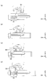
- FIG. 10 is a diagram for explaining the operation of the operation device 100 according to the embodiment.
- FIG. 10A shows an operating device 100 in a state in which the operating member 103 is not pushed in.
- FIG. 10B shows the operating device 100 in a state where the operating member 103 is pushed to a predetermined pushing position.
- FIG. 10C shows the operating device 100 in a state in which the operating member 103 is released from being pushed by the operator.
- FIG. 10D shows the operating device 100 in a state where the operating member 103 has returned to the initial position.
- the control device 120 causes the operating member 120 based on the rotation angle detection signal from the rotation angle detection sensor 106. Detecting that 103 has been pushed to a predetermined pushing position, the brake mechanism 107 is controlled so as to perform a braking operation. As a result, the brake mechanism 107 performs a braking operation to brake the rotation of the gear 102C and the pinion shaft 102D. As a result, the operating member 103 is held at a predetermined pushing position.
- the gear 102C is provided on the connecting mechanism 110 as shown in FIG. 10 (c). Due to the urging force from the compression coil spring 104 by the clearance ⁇ , the brake can rotate slightly counterclockwise (D2 direction in the figure) when viewed from the negative side of the Y axis. As a result, as shown in FIG. 10C, the operating member 103 can move slightly backward (in the X2 direction in the figure) by the clearance ⁇ .
- the control device 120 When the control device 120 detects that the operating member 103 has slightly moved backward based on the rotation angle detection signal from the rotation angle detection sensor 106, the control device 120 releases the braking of the gear 102C and the pinion shaft 102D by the brake mechanism 107. .. As a result, the operating member 103 is released from the state of being held at the predetermined pushing position, and can be returned to the initial position by the urging force from the compression coil spring 104 as shown in FIG. 10D.
- FIG. 11 is a graph showing an example of control by the control device 120 according to the embodiment.
- the vertical axis indicates the voltage value of the rotation angle detection signal.
- the horizontal axis represents time.
- the pushing amount gradually increases from the start of pushing the operating member 103 (timing t1) until the pushing position of the operating member 103 reaches a predetermined pushing position (timing t2). As it increases, the voltage value of the rotation angle detection signal gradually increases.
- the pushing position of the operating member 103 reaches a predetermined pushing position (timing t2)
- braking is applied by the brake mechanism 107 under the control of the braking control unit 123, and the operating member 103 is held at the predetermined pushing position. .. Therefore, the operator cannot push the operating member 103 any further. Therefore, the voltage value of the rotation angle detection signal is constant until the pressing of the operating member 103 is released (timing t2 to t3).
- the braking by the brake mechanism 107 is released by the control of the brake mechanism 107 by the control device 120.
- the operating member 103 is released from the state of being held at the predetermined pushing position, and returns to the initial position by the urging force from the compression coil spring 104.
- the control device 120 detects that the operating member 103 has been pushed to a predetermined pushing position based on the rotation angle detection signal output from the rotation angle detection sensor 106. , The state in which the operating member 103 is pushed in can be held by the brake mechanism 107. Then, the control device 120 according to the embodiment is based on the rotation angle detection signal, and the operating member is provided with a clearance ⁇ existing in the connecting mechanism 110 provided in the drive transmission system between the operating member 103 and the brake mechanism 107. When it is detected that the 103 has moved in the returning direction, the holding of the operating member 103 by the brake mechanism 107 can be released. Therefore, according to the control device 120 according to the embodiment, the operating member 103 is held by the brake mechanism 107 by detecting that the pushing operation by the operator is canceled without providing an additional contact sensor. The state can be released.
- FIG. 12 is a perspective view showing the configuration of the operating device 200 according to another embodiment.
- the operating device 200 includes a frame 201, an operating member 202, a compression coil spring 203, a motor 204, a rotation angle detection sensor 205, gears 206A to 206D, and a pinion shaft 207.
- the frame 201 is a member that accommodates and supports each component.
- the frame 201 has a left side wall portion 201a, a right side wall portion 201b, and a front wall portion 201c, and is formed by, for example, bending a metal plate.
- the operating member 202 is slidably provided in the front-rear direction (X-axis direction in the drawing) with respect to the frame 201.
- the operating member 202 can be pushed in by the operator, and by the pushing operation, the operating member 202 moves from the state of protruding rearward (negative direction of the X-axis in the figure) to the front (positive direction of the X-axis in the figure). , It is possible to change to a state of being pushed into the frame 201.
- a rack gear 202a having a plurality of teeth arranged in the front-rear direction is formed on the upper surface of the operating member 202.
- the rack gear 202a meshes with the gear 206D and constitutes the rack and pinion mechanism with the gear 206D.
- the operating member 202 can rotate the gear 206D via the rack and pinion mechanism as it moves in the front-rear direction (X-axis direction in the drawing).
- the compression coil spring 203 is provided so as to elastically deform in the front-rear direction (X-axis direction in the drawing) between the front end portion of the operating member 202 and the front wall portion 201c of the frame 201.
- the compression coil spring 203 urges the operating member 202 rearward (in the negative direction of the X-axis in the drawing). As a result, the operating member 202 can automatically return to the rear when it is released from the pushing operation.
- the motor 204 is an example of "braking means".
- the motor 204 is fixed to the outer surface of the right side wall portion 201b of the frame 201 so that its rotation shaft 204a penetrates the right side wall portion 201b and reaches the inside of the frame 201.
- a gear 206A is attached to the tip of the rotating shaft 204a.
- the rotation shaft 204a of the motor 204 is rotated by a control signal supplied from the control device 220, so that the operation member 202 is moved in the front-rear direction (X-axis direction in the drawing) via a plurality of gears 206A to 206D. Can be urged.
- the motor 204 stops the movement of the operating member 202 by braking the rotation of the gear 206A when the operating member 202 is pushed to the predetermined pushing position, and the operating member 202 reaches the predetermined pushing position. It can hold the pushed state.
- the motor 204 for example, a DC motor, a stepping motor, or the like can be used.
- the rotation angle detection sensor 205 is an example of "detection means".
- the rotation angle detection sensor 205 is provided on the outer surface of the left side wall portion 201a of the frame 201 and coaxially with the gear 206D and the pinion shaft 207, and detects the rotation angle of the gear 206D and the pinion shaft 207. It is attached to.
- the rotation angle detection sensor 205 has a case 205a and a rotor portion 205b.
- the rotor portion 205b is rotatably provided with respect to the case 205a.
- the rotor portion 205b is fitted with the tip portion 207a of the pinion shaft 207 penetrating the left side wall portion 201a.
- the rotor portion 205b rotates together with the gear 206D and the pinion shaft 207 as the operating member 202 is pushed in.
- the rotation angle detection sensor 205 detects the rotation angle
- the rotation angle detection sensor 205 outputs a rotation angle detection signal indicating the rotation angle to the control device 220.
- the rotation angle detected by the rotation angle detection sensor 205 is proportional to the pushing amount of the operating member 202. Therefore, the control device 220 can convert the rotation angle detected by the rotation angle detection sensor 205 into the pushing amount of the operating member 202 by a predetermined conversion formula.
- a resistance type, magnetic type, optical type, mechanical type or the like can be used.
- a linear position sensor that directly detects the pushing amount of the operating member 202 (that is, the moving amount of the operating member 202 in the front-rear direction) may be used.
- the control device 220 has the same configuration as the control device 120. Therefore, a detailed description of the control device 220 will be omitted.
- the operating device 200 configured in this way brakes the rotation of the gear 206A by the motor 204 to stop the movement of the operating member 202 for operation.
- the state in which the member 202 is pushed to a predetermined pushing position can be maintained.
- the force allows the operating member 202 to move slightly rearward (in the negative direction of the X-axis in the figure).
- the control device 220 detects that the operating member 202 has slightly moved backward based on the rotation angle detection signal output from the rotation angle detection sensor 205, the control device 220 releases the braking of the gear 206A by the motor 204.
- the operating member 202 is released from the state of being held at the predetermined pushing position, and can be returned to the initial position by the urging force from the compression coil spring 203.
- the control device 220 has detected that the operating member 202 has been pushed to a predetermined pushing position based on the rotation angle detection signal output from the rotation angle detection sensor 205.
- the motor 204 can hold the state in which the operating member 202 is pushed.
- the control device 220 according to the other embodiment moves in the direction in which the operating member 202 returns due to the backlash existing in the drive transmission system between the operating member 202 and the motor 204 based on the rotation angle detection signal.
- the holding of the operating member 202 by the brake mechanism 107 can be released. Therefore, according to the control device 220 according to the other embodiment, the operating member 103 is held by the brake mechanism 107 by detecting that the pushing operation by the operator has been eliminated without providing an additional contact sensor. The state can be released.
- Operation system 20 Operation target device 100 Operation device 101 Frame 102 Gear box 102C Gear 102D Pinion shaft 103 Operation member 104 Compression coil spring (biasing means) 105 Substrate 106 Rotation angle detection sensor (detection means) 107 Brake mechanism (braking means) 110 Connection mechanism (coupling joint) 111 1st joint 112 2nd joint 120 Control device 121 Detection signal acquisition unit 122 Pushing amount determination unit 123 Braking control unit 124 Operation signal output unit 200 Operation device 201 Frame 202 Operation member 203 Compression coil spring (biasing means) 204 motor (braking means) 205 Rotation angle detection sensor (detection means) 206A-206D Gear 207 Pinion Shaft 220 Control Unit
Landscapes
- Engineering & Computer Science (AREA)
- Multimedia (AREA)
- Physics & Mathematics (AREA)
- General Physics & Mathematics (AREA)
- Automation & Control Theory (AREA)
- Human Computer Interaction (AREA)
- General Engineering & Computer Science (AREA)
- Mechanical Engineering (AREA)
- Mechanical Control Devices (AREA)
Priority Applications (3)
| Application Number | Priority Date | Filing Date | Title |
|---|---|---|---|
| JP2021525916A JP7182708B2 (ja) | 2019-06-14 | 2020-03-11 | 制御装置および操作システム |
| CN202080039016.7A CN113906364B (zh) | 2019-06-14 | 2020-03-11 | 控制装置以及操作系统 |
| US17/643,599 US12072003B2 (en) | 2019-06-14 | 2021-12-10 | Controller and operation system |
Applications Claiming Priority (2)
| Application Number | Priority Date | Filing Date | Title |
|---|---|---|---|
| JP2019-111531 | 2019-06-14 | ||
| JP2019111531 | 2019-06-14 |
Related Child Applications (1)
| Application Number | Title | Priority Date | Filing Date |
|---|---|---|---|
| US17/643,599 Continuation US12072003B2 (en) | 2019-06-14 | 2021-12-10 | Controller and operation system |
Publications (1)
| Publication Number | Publication Date |
|---|---|
| WO2020250515A1 true WO2020250515A1 (ja) | 2020-12-17 |
Family
ID=73781952
Family Applications (1)
| Application Number | Title | Priority Date | Filing Date |
|---|---|---|---|
| PCT/JP2020/010565 Ceased WO2020250515A1 (ja) | 2019-06-14 | 2020-03-11 | 制御装置および操作システム |
Country Status (4)
| Country | Link |
|---|---|
| US (1) | US12072003B2 (https=) |
| JP (1) | JP7182708B2 (https=) |
| CN (1) | CN113906364B (https=) |
| WO (1) | WO2020250515A1 (https=) |
Citations (3)
| Publication number | Priority date | Publication date | Assignee | Title |
|---|---|---|---|---|
| JPH10261346A (ja) * | 1997-03-19 | 1998-09-29 | Sony Corp | 入力装置 |
| JP2000293298A (ja) * | 1999-04-08 | 2000-10-20 | Sega Enterp Ltd | 操作装置及びその制御方法 |
| JP2016067667A (ja) * | 2014-09-30 | 2016-05-09 | アルプス電気株式会社 | ゲーム用コントローラ |
Family Cites Families (4)
| Publication number | Priority date | Publication date | Assignee | Title |
|---|---|---|---|---|
| US5829745A (en) * | 1995-03-28 | 1998-11-03 | Home Arcade Systems, Inc. | Video game control unit with self-centering steering wheel |
| US6104382A (en) * | 1997-10-31 | 2000-08-15 | Immersion Corporation | Force feedback transmission mechanisms |
| US9122309B2 (en) * | 2012-11-13 | 2015-09-01 | Honeywell International Inc. | Active human-machine interface with force sensor overload protection |
| US10613629B2 (en) * | 2015-03-27 | 2020-04-07 | Chad Laurendeau | System and method for force feedback interface devices |
-
2020
- 2020-03-11 WO PCT/JP2020/010565 patent/WO2020250515A1/ja not_active Ceased
- 2020-03-11 JP JP2021525916A patent/JP7182708B2/ja active Active
- 2020-03-11 CN CN202080039016.7A patent/CN113906364B/zh active Active
-
2021
- 2021-12-10 US US17/643,599 patent/US12072003B2/en active Active
Patent Citations (3)
| Publication number | Priority date | Publication date | Assignee | Title |
|---|---|---|---|---|
| JPH10261346A (ja) * | 1997-03-19 | 1998-09-29 | Sony Corp | 入力装置 |
| JP2000293298A (ja) * | 1999-04-08 | 2000-10-20 | Sega Enterp Ltd | 操作装置及びその制御方法 |
| JP2016067667A (ja) * | 2014-09-30 | 2016-05-09 | アルプス電気株式会社 | ゲーム用コントローラ |
Also Published As
| Publication number | Publication date |
|---|---|
| US20220099166A1 (en) | 2022-03-31 |
| CN113906364A (zh) | 2022-01-07 |
| JPWO2020250515A1 (https=) | 2020-12-17 |
| JP7182708B2 (ja) | 2022-12-02 |
| CN113906364B (zh) | 2023-09-26 |
| US12072003B2 (en) | 2024-08-27 |
Similar Documents
| Publication | Publication Date | Title |
|---|---|---|
| JP5750296B2 (ja) | 車載用ディスプレイ装置 | |
| CN101389239B (zh) | 用于抽屉的配有电驱动单元的装置 | |
| KR20180041218A (ko) | 원격조작로봇시스템 | |
| JP5914840B2 (ja) | 電動工具の自動変速装置 | |
| US10935126B2 (en) | Shift device | |
| JPWO2018212203A1 (ja) | 把持システム | |
| KR20160069994A (ko) | 로봇 및 로봇 아암 | |
| JP2018204690A (ja) | 駆動装置およびロボット | |
| JP7182708B2 (ja) | 制御装置および操作システム | |
| CN115707890A (zh) | 电动致动器 | |
| JP2010105622A (ja) | 操作位置検出装置及びシフト操作位置検出装置 | |
| JP2009109274A (ja) | 回転角度検出装置 | |
| JP7253141B2 (ja) | 駆動装置、ロボットおよび画像形成装置 | |
| US10901451B2 (en) | Input device | |
| JP6785607B2 (ja) | 駆動装置 | |
| KR20150133113A (ko) | 이동형 테일 스톡 | |
| JP7441414B2 (ja) | 駆動装置、ロボット及び画像形成装置 | |
| JP7449680B2 (ja) | シリンジポンプ | |
| JP2024011082A (ja) | シフト装置 | |
| JP6953806B2 (ja) | 駆動装置およびロボット | |
| JP6221895B2 (ja) | レンズ位置調整機構,バリフォーカルレンズ,及び監視カメラ | |
| WO2018056253A1 (ja) | 駆動装置 | |
| JP6156682B2 (ja) | 電動アクチュエータおよびそれを備えた変速駆動装置 | |
| JP4155815B2 (ja) | 車載用操作装置及びその制御方法 | |
| JP4011032B2 (ja) | 車両スライド扉のスライド速度制御方法 |
Legal Events
| Date | Code | Title | Description |
|---|---|---|---|
| 121 | Ep: the epo has been informed by wipo that ep was designated in this application |
Ref document number: 20821585 Country of ref document: EP Kind code of ref document: A1 |
|
| ENP | Entry into the national phase |
Ref document number: 2021525916 Country of ref document: JP Kind code of ref document: A |
|
| NENP | Non-entry into the national phase |
Ref country code: DE |
|
| 122 | Ep: pct application non-entry in european phase |
Ref document number: 20821585 Country of ref document: EP Kind code of ref document: A1 |