WO2020250515A1 - Control device and operation system - Google Patents
Control device and operation system Download PDFInfo
- Publication number
- WO2020250515A1 WO2020250515A1 PCT/JP2020/010565 JP2020010565W WO2020250515A1 WO 2020250515 A1 WO2020250515 A1 WO 2020250515A1 JP 2020010565 W JP2020010565 W JP 2020010565W WO 2020250515 A1 WO2020250515 A1 WO 2020250515A1
- Authority
- WO
- WIPO (PCT)
- Prior art keywords
- operating member
- control device
- joint
- rotation angle
- detection signal
- Prior art date
Links
- 238000001514 detection method Methods 0.000 claims abstract description 91
- 230000005540 biological transmission Effects 0.000 claims abstract description 7
- 230000007246 mechanism Effects 0.000 claims description 58
- 230000008878 coupling Effects 0.000 claims description 3
- 238000010168 coupling process Methods 0.000 claims description 3
- 238000005859 coupling reaction Methods 0.000 claims description 3
- 238000013016 damping Methods 0.000 abstract 4
- 210000000078 claw Anatomy 0.000 description 26
- 230000006835 compression Effects 0.000 description 16
- 238000007906 compression Methods 0.000 description 16
- 239000000758 substrate Substances 0.000 description 11
- 238000000034 method Methods 0.000 description 7
- 238000006243 chemical reaction Methods 0.000 description 4
- 238000004891 communication Methods 0.000 description 4
- 238000010586 diagram Methods 0.000 description 3
- 230000008569 process Effects 0.000 description 3
- 230000004044 response Effects 0.000 description 3
- 230000008859 change Effects 0.000 description 2
- 238000012986 modification Methods 0.000 description 2
- 230000004048 modification Effects 0.000 description 2
- 230000003287 optical effect Effects 0.000 description 2
- 230000000149 penetrating effect Effects 0.000 description 2
- 238000005452 bending Methods 0.000 description 1
- 230000006870 function Effects 0.000 description 1
- 239000002184 metal Substances 0.000 description 1
Images


Classifications
-
- A—HUMAN NECESSITIES
- A63—SPORTS; GAMES; AMUSEMENTS
- A63F—CARD, BOARD, OR ROULETTE GAMES; INDOOR GAMES USING SMALL MOVING PLAYING BODIES; VIDEO GAMES; GAMES NOT OTHERWISE PROVIDED FOR
- A63F13/00—Video games, i.e. games using an electronically generated display having two or more dimensions
- A63F13/20—Input arrangements for video game devices
- A63F13/24—Constructional details thereof, e.g. game controllers with detachable joystick handles
-
- A—HUMAN NECESSITIES
- A63—SPORTS; GAMES; AMUSEMENTS
- A63F—CARD, BOARD, OR ROULETTE GAMES; INDOOR GAMES USING SMALL MOVING PLAYING BODIES; VIDEO GAMES; GAMES NOT OTHERWISE PROVIDED FOR
- A63F13/00—Video games, i.e. games using an electronically generated display having two or more dimensions
- A63F13/20—Input arrangements for video game devices
- A63F13/21—Input arrangements for video game devices characterised by their sensors, purposes or types
- A63F13/218—Input arrangements for video game devices characterised by their sensors, purposes or types using pressure sensors, e.g. generating a signal proportional to the pressure applied by the player
-
- G—PHYSICS
- G05—CONTROLLING; REGULATING
- G05G—CONTROL DEVICES OR SYSTEMS INSOFAR AS CHARACTERISED BY MECHANICAL FEATURES ONLY
- G05G1/00—Controlling members, e.g. knobs or handles; Assemblies or arrangements thereof; Indicating position of controlling members
- G05G1/015—Arrangements for indicating the position of a controlling member
-
- G—PHYSICS
- G05—CONTROLLING; REGULATING
- G05G—CONTROL DEVICES OR SYSTEMS INSOFAR AS CHARACTERISED BY MECHANICAL FEATURES ONLY
- G05G5/00—Means for preventing, limiting or returning the movements of parts of a control mechanism, e.g. locking controlling member
- G05G5/05—Means for returning or tending to return controlling members to an inoperative or neutral position, e.g. by providing return springs or resilient end-stops
-
- G—PHYSICS
- G05—CONTROLLING; REGULATING
- G05G—CONTROL DEVICES OR SYSTEMS INSOFAR AS CHARACTERISED BY MECHANICAL FEATURES ONLY
- G05G5/00—Means for preventing, limiting or returning the movements of parts of a control mechanism, e.g. locking controlling member
- G05G5/06—Means for preventing, limiting or returning the movements of parts of a control mechanism, e.g. locking controlling member for holding members in one or a limited number of definite positions only
-
- A—HUMAN NECESSITIES
- A63—SPORTS; GAMES; AMUSEMENTS
- A63F—CARD, BOARD, OR ROULETTE GAMES; INDOOR GAMES USING SMALL MOVING PLAYING BODIES; VIDEO GAMES; GAMES NOT OTHERWISE PROVIDED FOR
- A63F2300/00—Features of games using an electronically generated display having two or more dimensions, e.g. on a television screen, showing representations related to the game
- A63F2300/10—Features of games using an electronically generated display having two or more dimensions, e.g. on a television screen, showing representations related to the game characterized by input arrangements for converting player-generated signals into game device control signals
- A63F2300/1043—Features of games using an electronically generated display having two or more dimensions, e.g. on a television screen, showing representations related to the game characterized by input arrangements for converting player-generated signals into game device control signals being characterized by constructional details
-
- F—MECHANICAL ENGINEERING; LIGHTING; HEATING; WEAPONS; BLASTING
- F16—ENGINEERING ELEMENTS AND UNITS; GENERAL MEASURES FOR PRODUCING AND MAINTAINING EFFECTIVE FUNCTIONING OF MACHINES OR INSTALLATIONS; THERMAL INSULATION IN GENERAL
- F16H—GEARING
- F16H19/00—Gearings comprising essentially only toothed gears or friction members and not capable of conveying indefinitely-continuing rotary motion
- F16H19/02—Gearings comprising essentially only toothed gears or friction members and not capable of conveying indefinitely-continuing rotary motion for interconverting rotary or oscillating motion and reciprocating motion
- F16H19/04—Gearings comprising essentially only toothed gears or friction members and not capable of conveying indefinitely-continuing rotary motion for interconverting rotary or oscillating motion and reciprocating motion comprising a rack
- F16H2019/046—Facilitating the engagement or stopping of racks
-
- G—PHYSICS
- G05—CONTROLLING; REGULATING
- G05G—CONTROL DEVICES OR SYSTEMS INSOFAR AS CHARACTERISED BY MECHANICAL FEATURES ONLY
- G05G1/00—Controlling members, e.g. knobs or handles; Assemblies or arrangements thereof; Indicating position of controlling members
- G05G1/02—Controlling members for hand actuation by linear movement, e.g. push buttons
-
- H—ELECTRICITY
- H01—ELECTRIC ELEMENTS
- H01H—ELECTRIC SWITCHES; RELAYS; SELECTORS; EMERGENCY PROTECTIVE DEVICES
- H01H13/00—Switches having rectilinearly-movable operating part or parts adapted for pushing or pulling in one direction only, e.g. push-button switch
- H01H13/02—Details
- H01H13/12—Movable parts; Contacts mounted thereon
- H01H13/20—Driving mechanisms
-
- H—ELECTRICITY
- H01—ELECTRIC ELEMENTS
- H01H—ELECTRIC SWITCHES; RELAYS; SELECTORS; EMERGENCY PROTECTIVE DEVICES
- H01H3/00—Mechanisms for operating contacts
- H01H2003/008—Mechanisms for operating contacts with a haptic or a tactile feedback controlled by electrical means, e.g. a motor or magnetofriction
-
- H—ELECTRICITY
- H01—ELECTRIC ELEMENTS
- H01H—ELECTRIC SWITCHES; RELAYS; SELECTORS; EMERGENCY PROTECTIVE DEVICES
- H01H3/00—Mechanisms for operating contacts
- H01H3/32—Driving mechanisms, i.e. for transmitting driving force to the contacts
- H01H3/40—Driving mechanisms, i.e. for transmitting driving force to the contacts using friction, toothed, or screw-and-nut gearing
Definitions
- the present invention relates to a control device and an operation system.
- an operation member that can be pushed by an operator and an operation member are urged to initially perform an operation member when the push operation of the operation member is released.
- an urging means for example, a coil spring or the like
- Patent Document 1 in a game controller provided with an operation unit that can be pushed in, a motor that applies a force to the operation unit is provided, and the operation of the motor is controlled.
- a technique that makes it possible to limit the amount of movement of the operation unit is disclosed.
- the control device of one embodiment is a control device that controls the operation device, and the operation device includes an operation member that can be pushed and operated by the operator, an urging means that urges the operation member in the return direction, and an operation member.
- the control device has a detection means that detects the movement amount of the vehicle and outputs a detection signal indicating the movement amount, and a braking means that brakes the movement of the operation member.
- the control device has the operation member based on the detection signal. When it is detected that the operating member has been pushed to a predetermined pushing position, the braking means holds the pushed state of the operating member, and based on the detection signal, the clearance existing in the drive transmission system between the operating member and the braking means. When it is detected that the operating member has moved in the returning direction, the holding operation by the braking means is released.
- External perspective view of the operating device External perspective view of the operating device according to one embodiment External perspective view of the operating device according to one embodiment External perspective view of the operating device according to one embodiment Left side view of the operating device according to one embodiment External perspective view of the connecting mechanism according to one embodiment An exploded perspective view of the connecting mechanism according to the embodiment.
- a perspective sectional view of a connecting mechanism according to an embodiment. A block diagram showing a system configuration of an operation system according to an embodiment A flowchart showing a processing procedure by the control device according to the embodiment. The figure for demonstrating the operation of the operation apparatus which concerns on one Embodiment A graph showing an example of control by the control device according to one embodiment.
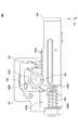
- FIG. 1 to 3 are external perspective views of the operating device 100 according to the embodiment.
- FIG. 2 shows the operating device 100 in a state where the frame 101 is removed.
- FIG. 3 shows the bottom surface side (Z-axis negative side) of the operating device 100 shown in FIG.
- FIG. 4 is a left side view of the operation device 100 according to the embodiment.
- FIG. 4 shows the operating device 100 in a state where the frame 101, the substrate 105, and the rotation angle detection sensor 106 are removed.
- the X-axis direction in the figure is the front-back direction
- the Y-axis direction in the figure is the left-right direction
- the Z-axis direction in the figure is the up-down direction.
- the positive direction of the X-axis is the front
- the positive direction of the Y-axis is the right
- the positive direction of the Z-axis is the top.
- the operating device 100 includes a frame 101, a gearbox 102, an operating member 103, a compression coil spring 104, a substrate 105, a rotation angle detection sensor 106, a brake mechanism 107, and a connecting mechanism 110. There is.
- the frame 101 is a member that supports each component.
- the frame 101 supports the substrate 105 and the rotation angle detection sensor 106 arranged on the left side (Y-axis negative side) of the frame 101.
- the frame 101 supports a gearbox 102 arranged on the right side (Y-axis positive side) of the frame 101.
- the gear box 102 has a space 102A, a front wall surface 102B, a gear 102C, and a pinion shaft 102D.
- a gear 102C, a pinion shaft 102D, an operating member 103, and a compression coil spring 104 are arranged inside the space 102A.
- the gear 102C and the pinion shaft 102D are examples of the "rotating member", and are rotatably provided around the axis of the rotating shaft AX (see FIG. 4) parallel to the Y axis inside the space 102A.
- the gear 102C is provided coaxially with the pinion shaft 102D and is fixed to the pinion shaft 102D. As a result, the gear 102C rotates together with the pinion shaft 102D.
- the front wall surface 102B is a wall surface exposed to the space 102A, and is a wall surface facing the front end surface 103B of the operating member 103.
- the operating member 103 is slidably provided in the front-rear direction (X-axis direction in the drawing) in the space 102A formed in the gear box 102.
- the operating member 103 is a member having a substantially square columnar shape (but not limited to this) extending in the front-rear direction (X-axis direction in the drawing).
- the operating member 103 can be moved forward (in the positive direction of the X-axis) in the space 102A of the gearbox 102 by a pushing operation by the operator.
- a rack gear 103A in which a plurality of teeth are arranged in the front-rear direction is formed on the upper surface of the operating member 103.
- the rack gear 103A meshes with the gear 102C provided in the space 102A of the gear box 102, and constitutes the rack and pinion mechanism with the gear 102C.
- the operating member 103 can rotate the gear 102C via the rack and pinion mechanism as it moves in the front-rear direction (X-axis direction in the drawing).
- the compression coil spring 104 is an example of the "urging means".
- the compression coil spring 104 is provided so as to be elastically deformed in the front-rear direction (X-axis direction in the drawing) between the front end surface 103B of the operating member 103 and the front wall surface 102B of the gearbox 102.
- the compression coil spring 104 urges the operating member 103 rearward (in the negative direction of the X-axis in the drawing). As a result, the operating member 103 can automatically return to the rear when it is released from the pushing operation.
- the substrate 105 is a flat plate-shaped member on which various electric components (for example, rotation angle detection sensor 106, etc.) are mounted.
- the substrate 105 is provided on the rotation axis AX and is fixed to the left side (Y-axis negative side) of the frame 101.
- a rigid substrate such as PWB (Printed Wiring Board) is used.
- the rotation angle detection sensor 106 is an example of "detection means".
- the rotation angle detection sensor 106 is provided on the rotation shaft AX, and detects the rotation angles of the gear 102C and the pinion shaft 102D.
- the rotation angle detection sensor 106 is mounted on the surface of the substrate 105 (the surface on the negative side of the Y-axis).
- the rotation angle detection sensor 106 has a case 106a and a rotor portion 106b.
- the case 106a is fixed to the surface of the substrate 105 (the surface on the negative side of the Y-axis) and accommodates the rotor portion 106b.
- the rotor portion 106b is rotatably provided inside the case 106a.
- the rotor portion 106b is fitted with the tip portion of the pinion shaft 102D penetrating the substrate 105. As a result, the rotor portion 106b rotates together with the gear 102C and the pinion shaft 102D as the operating member 103 is pushed in.
- the rotation angle detection sensor 106 detects the rotation angle
- the rotation angle detection sensor 106 outputs a rotation angle detection signal indicating the rotation angle to the control device 120.
- the rotation angle detected by the rotation angle detection sensor 106 is proportional to the pushing amount of the operating member 103. Therefore, the control device 120 can convert the rotation angle detected by the rotation angle detection sensor 106 into the pushing amount of the operating member 103 by a predetermined conversion formula.
- rotation angle detection sensor 106 a resistance type, magnetic type, optical type, mechanical type or the like can be used. Further, instead of the rotation angle detection sensor 106, a linear position sensor that directly detects the pushing amount of the operating member 202 (that is, the moving amount of the operating member 103 in the front-rear direction) may be used.
- the brake mechanism 107 is an example of "braking means".
- the brake mechanism 107 is provided on the rotating shaft AX and is connected to the pinion shaft 102D via the connecting mechanism 110.
- the brake mechanism 107 operates in response to a control signal supplied from the outside to brake the rotation of the gear 102C and the pinion shaft 102D.
- a so-called electromagnetic brake is used as the brake mechanism 107.
- the connecting mechanism 110 is provided on the rotating shaft AX and between the pinion shaft 102D and the brake mechanism 107.
- the connecting mechanism 110 connects the brake mechanism 107 to the pinion shaft 102D.
- a so-called coupling joint is used as the connecting mechanism 110.
- the electrical connection configuration (for example, flexible wiring board, etc.) of the operating device 100 with the outside is not shown.
- the operating device 100 has at least an electrical connection configuration for supplying a control signal to the brake mechanism 107 from the outside and an electrical connection for outputting the rotation angle detection signal from the rotation angle detection sensor 106 to the outside. It has a connection configuration.
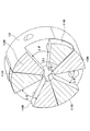
- FIG. 5 is an external perspective view of the connecting mechanism 110 according to the embodiment.
- FIG. 6 is an exploded perspective view of the connecting mechanism 110 according to the embodiment.
- FIG. 7 is a perspective sectional view of the connecting mechanism 110 according to the embodiment.
- the connecting mechanism 110 has a first joint 111 and a second joint 112.
- the first joint 111 is attached to the tip of the pinion shaft 102D and rotates together with the pinion shaft 102D.
- the first joint 111 has three claws 111B protruding toward the second joint 112 on the surface 111A facing the second joint 112.
- the three claw portions 111B are arranged at intervals of 120 ° on concentric circles centered on the rotation axis AX. Further, each of the three claw portions 111B has a fan shape having a predetermined central angle ⁇ 1 when viewed from the axial direction of the rotation axis AX.
- the second joint 112 is attached to the tip of a shaft included in the brake mechanism 107 and rotates together with the shaft.
- the second joint 112 has three claws 112B protruding toward the first joint 111 on the surface 112A facing the first joint 111.
- the three claw portions 112B are arranged at intervals of 120 ° on concentric circles centered on the rotation axis AX. Further, each of the three claw portions 112B has a fan shape having a predetermined central angle ⁇ 1 when viewed from the axial direction of the rotation axis AX.
- the connecting mechanism 110 configured in this way, the three claws 111B of the first joint 111 and the three claws 112B of the second joint 112 mesh with each other to form the second joint 112 together with the first joint 111. It is designed to rotate.
- the first joint 111 is clockwise (D1 direction shown in FIG. 5) when viewed from the Y-axis negative side.
- the side surface of each of the three claws 111B on the clockwise side abuts on the side surface of each of the three claws 112B in the clockwise direction, thereby rotating the second joint 112 clockwise. ..
- the first joint 111 rotates counterclockwise (D2 direction shown in FIG. 5) when viewed from the Y-axis negative side.
- the side surface of each of the three claws 111B on the counterclockwise direction comes into contact with the side surface of each of the three claws 112B in the counterclockwise direction, so that the second joint 112 is counterclockwise. Rotate.
- the fan-shaped central angle ⁇ 2 formed by the space 112C between the two adjacent claw portions 112B is from the fan-shaped central angle ⁇ 1 formed by the claw portion 111B fitted in the space 112C. Is also getting bigger.
- the connecting mechanism 110 of the present embodiment is provided with a clearance ⁇ between the claw portions 111B and the claw portions 112B that are adjacent to each other even when the rotation of the second joint 112 is being braked by the brake mechanism 107.
- the first joint 111 can rotate by this clearance ⁇ .
- the examples shown in FIGS. 5 to 7 represent the connecting mechanism 110 when the operating member 103 is pushed in, and the side surfaces of the three claw portions 111B on the clockwise side are in the traveling direction. It is in contact with each side surface of the one claw portion 112B. Therefore, a clearance ⁇ exists between the side surface of each of the three claw portions 111B on the counterclockwise direction side and the side surface of each of the three claw portions 112B in the counterclockwise direction. .. Therefore, even when the rotation of the second joint 112 is being braked by the brake mechanism 107, the first joint 111 can rotate in the counterclockwise direction by the clearance ⁇ .
- FIG. 8 is a block diagram showing a system configuration of the operation system 10 according to the embodiment. As shown in FIG. 8, the operation system 10 includes an operation device 100 and a control device 120.
- the control device 120 is a device capable of controlling the braking operation of the brake mechanism 107 included in the operation device 100. As shown in FIG. 8, the control device 120 includes a detection signal acquisition unit 121, a push-in amount determination unit 122, a braking control unit 123, and an operation signal output unit 124.
- the detection signal acquisition unit 121 acquires the rotation angle detection signal output from the rotation angle detection sensor 106 included in the operating device 100.
- the push-in amount determination unit 122 determines the push-in amount of the operating member 103 based on the rotation angle detection signal acquired by the detection signal acquisition unit 121. For example, in the rotation angle detection signal output from the rotation angle detection sensor 106, the voltage value of the rotation angle detection signal changes according to the rotation angle of the gear 102C and the pinion shaft 102D (that is, the pushing amount of the operating member 103). To do. Therefore, the push-in amount determination unit 122 can derive the push-in amount of the operating member 103 from the voltage value of the rotation angle detection signal by a predetermined conversion formula or a predetermined conversion table.
- the braking control unit 123 is a brake mechanism 107 included in the operation device 100 based on the rotation angle detection signal acquired by the detection signal acquisition unit 121 and the push amount of the operation member 103 determined by the push amount determination unit 122. Control braking operation.
- the brake mechanism 107 when the braking control unit 123 detects that the operating member 103 has been pushed to a predetermined pushing position based on the pushing amount determined by the pushing amount determining unit 122, the brake mechanism 107 has the gear 102C and the pinion shaft. By braking the rotation of the 102D, the brake mechanism 107 can hold the state in which the operating member 103 is pushed.
- the braking control unit 123 is geared by the clearance existing in the connecting mechanism 110.
- the reverse rotation of the 102C and the pinion shaft 102D can be detected based on the rotation angle detection signal acquired by the detection signal acquisition unit 121, and the holding operation by the brake mechanism 107 can be released.
- the control device 120 can arbitrarily set a predetermined pushing position of the operating member 103 in a memory or the like. As a result, for example, the control device 120 can change a predetermined pushing position according to the purpose of use and the usage situation (for example, game type, scene, setting, etc.) of the control device 120.
- the operation signal output unit 124 outputs an operation signal indicating the push amount of the operation member 103 determined by the push amount determination unit 122 to the operation target device 20.
- the operation target device 20 include, for example, a game machine, an in-vehicle device (for example, a navigation device), and the like, but the device is not limited to these and may be any device.
- Each function of the control device 120 described above is, for example, a CPU (Central Processing Unit) for a program stored in a memory (for example, ROM (Read Only Memory), RAM (Random Access Memory), etc.) in the control device 120. (An example of "computer”) is realized by executing.
- a CPU Central Processing Unit
- ROM Read Only Memory
- RAM Random Access Memory
- the control device 120 may be a device physically provided inside the operation device 100 (for example, an IC (Integrated Circuit) or the like), and is physically provided outside the operation device 100. It may be a device. Further, the control device 120 may be connected to the operation device 100 by wire (for example, a communication cable), or may be connected wirelessly (for example, Bluetooth (registered trademark), Wi-Fi (registered trademark), infrared communication, etc.). You may.
- wire for example, a communication cable
- wirelessly for example, Bluetooth (registered trademark), Wi-Fi (registered trademark), infrared communication, etc.
- control device 120 may be a device (for example, an IC or the like) physically provided inside the operation target device 20, or a device physically provided outside the operation target device 20. There may be. Further, the control device 120 may be connected to the operation target device 20 by wire (for example, a communication cable), and may be connected to the operation target device 20 wirelessly (for example, Bluetooth (registered trademark), Wi-Fi (registered trademark), infrared rays). It may be connected by communication etc.).
- FIG. 9 is a flowchart showing a processing procedure by the control device 120 according to the embodiment.
- the detection signal acquisition unit 121 acquires the rotation angle detection signal output from the rotation angle detection sensor 106 of the operating device 100 (step S901).
- the push-in amount determination unit 122 determines the push-in amount of the operating member 103 based on the rotation angle detection signal acquired in step S901 (step S902).
- the braking control unit 123 determines whether or not the operating member 103 has been pushed to a predetermined pushing position based on the pushing amount determined in step S902 (step S903).
- step S903 If it is determined in step S903 that the operating member 103 has not been pushed to the predetermined pushing position (step S903: No), the control device 120 returns the process to step S901.
- step S903 when it is determined in step S903 that the operating member 103 has been pushed to a predetermined pushing position (step S903: Yes), the braking control unit 123 causes the brake mechanism 107 to brake the rotation of the gear 102C and the pinion shaft 102D. As a result, the operating member 103 is held in the pushed state (step S904).
- the detection signal acquisition unit 121 acquires the rotation angle detection signal output from the rotation angle detection sensor 106 of the operating device 100 (step S905). Then, the braking control unit 123 determines whether or not the operating member 103 has moved by a predetermined amount or more in the return direction based on the rotation angle detection signal acquired in step S905 (step S906).
- step S906 If it is determined in step S906 that the operating member 103 has not moved by a predetermined amount or more in the return direction (step S906: No), the control device 120 returns the process to step S905.
- step S906 when it is determined that the operating member 103 has moved by a predetermined amount or more in the return direction (step S906: Yes), the braking control unit 123 releases the braking by the braking mechanism 107, so that the operating member 103 Releases the holding of the pushed state (step S907). Then, the control device 120 ends a series of processes shown in FIG.
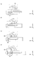
- FIG. 10 is a diagram for explaining the operation of the operation device 100 according to the embodiment.
- FIG. 10A shows an operating device 100 in a state in which the operating member 103 is not pushed in.
- FIG. 10B shows the operating device 100 in a state where the operating member 103 is pushed to a predetermined pushing position.
- FIG. 10C shows the operating device 100 in a state in which the operating member 103 is released from being pushed by the operator.
- FIG. 10D shows the operating device 100 in a state where the operating member 103 has returned to the initial position.
- the control device 120 causes the operating member 120 based on the rotation angle detection signal from the rotation angle detection sensor 106. Detecting that 103 has been pushed to a predetermined pushing position, the brake mechanism 107 is controlled so as to perform a braking operation. As a result, the brake mechanism 107 performs a braking operation to brake the rotation of the gear 102C and the pinion shaft 102D. As a result, the operating member 103 is held at a predetermined pushing position.
- the gear 102C is provided on the connecting mechanism 110 as shown in FIG. 10 (c). Due to the urging force from the compression coil spring 104 by the clearance ⁇ , the brake can rotate slightly counterclockwise (D2 direction in the figure) when viewed from the negative side of the Y axis. As a result, as shown in FIG. 10C, the operating member 103 can move slightly backward (in the X2 direction in the figure) by the clearance ⁇ .
- the control device 120 When the control device 120 detects that the operating member 103 has slightly moved backward based on the rotation angle detection signal from the rotation angle detection sensor 106, the control device 120 releases the braking of the gear 102C and the pinion shaft 102D by the brake mechanism 107. .. As a result, the operating member 103 is released from the state of being held at the predetermined pushing position, and can be returned to the initial position by the urging force from the compression coil spring 104 as shown in FIG. 10D.
- FIG. 11 is a graph showing an example of control by the control device 120 according to the embodiment.
- the vertical axis indicates the voltage value of the rotation angle detection signal.
- the horizontal axis represents time.
- the pushing amount gradually increases from the start of pushing the operating member 103 (timing t1) until the pushing position of the operating member 103 reaches a predetermined pushing position (timing t2). As it increases, the voltage value of the rotation angle detection signal gradually increases.
- the pushing position of the operating member 103 reaches a predetermined pushing position (timing t2)
- braking is applied by the brake mechanism 107 under the control of the braking control unit 123, and the operating member 103 is held at the predetermined pushing position. .. Therefore, the operator cannot push the operating member 103 any further. Therefore, the voltage value of the rotation angle detection signal is constant until the pressing of the operating member 103 is released (timing t2 to t3).
- the braking by the brake mechanism 107 is released by the control of the brake mechanism 107 by the control device 120.
- the operating member 103 is released from the state of being held at the predetermined pushing position, and returns to the initial position by the urging force from the compression coil spring 104.
- the control device 120 detects that the operating member 103 has been pushed to a predetermined pushing position based on the rotation angle detection signal output from the rotation angle detection sensor 106. , The state in which the operating member 103 is pushed in can be held by the brake mechanism 107. Then, the control device 120 according to the embodiment is based on the rotation angle detection signal, and the operating member is provided with a clearance ⁇ existing in the connecting mechanism 110 provided in the drive transmission system between the operating member 103 and the brake mechanism 107. When it is detected that the 103 has moved in the returning direction, the holding of the operating member 103 by the brake mechanism 107 can be released. Therefore, according to the control device 120 according to the embodiment, the operating member 103 is held by the brake mechanism 107 by detecting that the pushing operation by the operator is canceled without providing an additional contact sensor. The state can be released.
- FIG. 12 is a perspective view showing the configuration of the operating device 200 according to another embodiment.
- the operating device 200 includes a frame 201, an operating member 202, a compression coil spring 203, a motor 204, a rotation angle detection sensor 205, gears 206A to 206D, and a pinion shaft 207.
- the frame 201 is a member that accommodates and supports each component.
- the frame 201 has a left side wall portion 201a, a right side wall portion 201b, and a front wall portion 201c, and is formed by, for example, bending a metal plate.
- the operating member 202 is slidably provided in the front-rear direction (X-axis direction in the drawing) with respect to the frame 201.
- the operating member 202 can be pushed in by the operator, and by the pushing operation, the operating member 202 moves from the state of protruding rearward (negative direction of the X-axis in the figure) to the front (positive direction of the X-axis in the figure). , It is possible to change to a state of being pushed into the frame 201.
- a rack gear 202a having a plurality of teeth arranged in the front-rear direction is formed on the upper surface of the operating member 202.
- the rack gear 202a meshes with the gear 206D and constitutes the rack and pinion mechanism with the gear 206D.
- the operating member 202 can rotate the gear 206D via the rack and pinion mechanism as it moves in the front-rear direction (X-axis direction in the drawing).
- the compression coil spring 203 is provided so as to elastically deform in the front-rear direction (X-axis direction in the drawing) between the front end portion of the operating member 202 and the front wall portion 201c of the frame 201.
- the compression coil spring 203 urges the operating member 202 rearward (in the negative direction of the X-axis in the drawing). As a result, the operating member 202 can automatically return to the rear when it is released from the pushing operation.
- the motor 204 is an example of "braking means".
- the motor 204 is fixed to the outer surface of the right side wall portion 201b of the frame 201 so that its rotation shaft 204a penetrates the right side wall portion 201b and reaches the inside of the frame 201.
- a gear 206A is attached to the tip of the rotating shaft 204a.
- the rotation shaft 204a of the motor 204 is rotated by a control signal supplied from the control device 220, so that the operation member 202 is moved in the front-rear direction (X-axis direction in the drawing) via a plurality of gears 206A to 206D. Can be urged.
- the motor 204 stops the movement of the operating member 202 by braking the rotation of the gear 206A when the operating member 202 is pushed to the predetermined pushing position, and the operating member 202 reaches the predetermined pushing position. It can hold the pushed state.
- the motor 204 for example, a DC motor, a stepping motor, or the like can be used.
- the rotation angle detection sensor 205 is an example of "detection means".
- the rotation angle detection sensor 205 is provided on the outer surface of the left side wall portion 201a of the frame 201 and coaxially with the gear 206D and the pinion shaft 207, and detects the rotation angle of the gear 206D and the pinion shaft 207. It is attached to.
- the rotation angle detection sensor 205 has a case 205a and a rotor portion 205b.
- the rotor portion 205b is rotatably provided with respect to the case 205a.
- the rotor portion 205b is fitted with the tip portion 207a of the pinion shaft 207 penetrating the left side wall portion 201a.
- the rotor portion 205b rotates together with the gear 206D and the pinion shaft 207 as the operating member 202 is pushed in.
- the rotation angle detection sensor 205 detects the rotation angle
- the rotation angle detection sensor 205 outputs a rotation angle detection signal indicating the rotation angle to the control device 220.
- the rotation angle detected by the rotation angle detection sensor 205 is proportional to the pushing amount of the operating member 202. Therefore, the control device 220 can convert the rotation angle detected by the rotation angle detection sensor 205 into the pushing amount of the operating member 202 by a predetermined conversion formula.
- a resistance type, magnetic type, optical type, mechanical type or the like can be used.
- a linear position sensor that directly detects the pushing amount of the operating member 202 (that is, the moving amount of the operating member 202 in the front-rear direction) may be used.
- the control device 220 has the same configuration as the control device 120. Therefore, a detailed description of the control device 220 will be omitted.
- the operating device 200 configured in this way brakes the rotation of the gear 206A by the motor 204 to stop the movement of the operating member 202 for operation.
- the state in which the member 202 is pushed to a predetermined pushing position can be maintained.
- the force allows the operating member 202 to move slightly rearward (in the negative direction of the X-axis in the figure).
- the control device 220 detects that the operating member 202 has slightly moved backward based on the rotation angle detection signal output from the rotation angle detection sensor 205, the control device 220 releases the braking of the gear 206A by the motor 204.
- the operating member 202 is released from the state of being held at the predetermined pushing position, and can be returned to the initial position by the urging force from the compression coil spring 203.
- the control device 220 has detected that the operating member 202 has been pushed to a predetermined pushing position based on the rotation angle detection signal output from the rotation angle detection sensor 205.
- the motor 204 can hold the state in which the operating member 202 is pushed.
- the control device 220 according to the other embodiment moves in the direction in which the operating member 202 returns due to the backlash existing in the drive transmission system between the operating member 202 and the motor 204 based on the rotation angle detection signal.
- the holding of the operating member 202 by the brake mechanism 107 can be released. Therefore, according to the control device 220 according to the other embodiment, the operating member 103 is held by the brake mechanism 107 by detecting that the pushing operation by the operator has been eliminated without providing an additional contact sensor. The state can be released.
- Operation system 20 Operation target device 100 Operation device 101 Frame 102 Gear box 102C Gear 102D Pinion shaft 103 Operation member 104 Compression coil spring (biasing means) 105 Substrate 106 Rotation angle detection sensor (detection means) 107 Brake mechanism (braking means) 110 Connection mechanism (coupling joint) 111 1st joint 112 2nd joint 120 Control device 121 Detection signal acquisition unit 122 Pushing amount determination unit 123 Braking control unit 124 Operation signal output unit 200 Operation device 201 Frame 202 Operation member 203 Compression coil spring (biasing means) 204 motor (braking means) 205 Rotation angle detection sensor (detection means) 206A-206D Gear 207 Pinion Shaft 220 Control Unit
Abstract
A control device of the present invention controls an operation device. The operation device comprises: an operation member that can be pressed by an operator; a biasing means that biases the operation member in a return direction; a detection means that detects a movement amount of the operation member and outputs a detection signal indicating the movement amount; and a damping means that dampens movement of the operation member. When, on the basis of the detection signal, it is detected that the operation member has been pressed to a predetermined pressed position, the control device causes the damping means to hold the pressed state of the operation member; and when, on the basis of the detection signal, it is detected, from a clearance present in a drive transmission system between the operation member and the damping means, that the operation member has moved in the return direction, the control device cancels the holding action of the damping means.
Description
本発明は、制御装置および操作システムに関する。
The present invention relates to a control device and an operation system.
従来、ゲーム機のコントローラ等に用いられる操作装置として、操作者による押し込み操作可能な操作部材と、操作部材を付勢することにより、操作部材の押し込み操作が解除されたときに、操作部材を初期位置に復帰させる付勢手段(例えば、コイルスプリング等)とを備えたものが知られている。
Conventionally, as an operation device used for a controller of a game machine or the like, an operation member that can be pushed by an operator and an operation member are urged to initially perform an operation member when the push operation of the operation member is released. Those provided with an urging means (for example, a coil spring or the like) for returning to a position are known.
このような操作装置に関し、例えば、下記特許文献1には、押し込み操作可能な操作部を備えたゲーム用コントローラにおいて、操作部に力を与えるモータを設け、当該モータの動作を制御することによって、操作部の移動量を制限できるようにした技術が開示されている。
Regarding such an operation device, for example, in Patent Document 1 below, in a game controller provided with an operation unit that can be pushed in, a motor that applies a force to the operation unit is provided, and the operation of the motor is controlled. A technique that makes it possible to limit the amount of movement of the operation unit is disclosed.
しかしながら、従来の操作装置では、制動手段によって操作部材が押し込まれた状態を保持することが可能な構成を採用した場合、押し込み操作が解消されたときに操作部材を初期位置に復帰させるためには、操作者による押し込み操作が解消されたことを検知するための接触センサ(例えば、静電センサ等)を追加で設ける必要がある。
However, in the conventional operating device, when a configuration is adopted in which the operating member can be held in a pushed state by the braking means, in order to return the operating member to the initial position when the pushing operation is canceled. , It is necessary to additionally provide a contact sensor (for example, an electrostatic sensor) for detecting that the pushing operation by the operator has been eliminated.
一実施形態の制御装置は、操作装置を制御する制御装置であって、操作装置は、操作者による押し込み操作可能な操作部材と、操作部材を復帰方向に付勢する付勢手段と、操作部材の移動量を検知して、当該移動量を示す検出信号を出力する検出手段と、操作部材の移動を制動する制動手段と、を有し、制御装置は、検出信号に基づいて、操作部材が所定の押し込み位置まで押し込まれたことを検出した場合、操作部材が押し込まれた状態を制動手段に保持させ、検出信号に基づいて、操作部材と制動手段との間の駆動伝達系に存在するクリアランスにより、操作部材が復帰する方向に移動したことを検出した場合、制動手段による保持動作を解除させる。
The control device of one embodiment is a control device that controls the operation device, and the operation device includes an operation member that can be pushed and operated by the operator, an urging means that urges the operation member in the return direction, and an operation member. The control device has a detection means that detects the movement amount of the vehicle and outputs a detection signal indicating the movement amount, and a braking means that brakes the movement of the operation member. The control device has the operation member based on the detection signal. When it is detected that the operating member has been pushed to a predetermined pushing position, the braking means holds the pushed state of the operating member, and based on the detection signal, the clearance existing in the drive transmission system between the operating member and the braking means. When it is detected that the operating member has moved in the returning direction, the holding operation by the braking means is released.
一実施形態によれば、追加の接触センサを設けることなく、操作者による押し込み操作が解消されたことを検知して、制動手段によって操作部材が保持された状態を解除することができる。
According to one embodiment, it is possible to detect that the pushing operation by the operator has been canceled and release the state in which the operating member is held by the braking means without providing an additional contact sensor.
以下、図面を参照して、一実施形態について説明する。
Hereinafter, one embodiment will be described with reference to the drawings.
(操作装置100の構成)
図1~図3は、一実施形態に係る操作装置100の外観斜視図である。但し、図2は、フレーム101が取り除かれた状態の操作装置100を表している。また、図3は、図2に示す操作装置100の底面側(Z軸負側)を表している。また、図4は、一実施形態に係る操作装置100の左側面図である。但し、図4では、フレーム101、基板105、および回転角度検出センサ106が取り除かれた状態の操作装置100を表している。なお、以降の説明では、便宜上、図中X軸方向を、前後方向とし、図中Y軸方向を、左右方向とし、図中Z軸方向を、上下方向とする。但し、X軸正方向を前、Y軸正方向を右、Z軸正方向を上とする。 (Configuration of Operation Device 100)
1 to 3 are external perspective views of theoperating device 100 according to the embodiment. However, FIG. 2 shows the operating device 100 in a state where the frame 101 is removed. Further, FIG. 3 shows the bottom surface side (Z-axis negative side) of the operating device 100 shown in FIG. Further, FIG. 4 is a left side view of the operation device 100 according to the embodiment. However, FIG. 4 shows the operating device 100 in a state where the frame 101, the substrate 105, and the rotation angle detection sensor 106 are removed. In the following description, for convenience, the X-axis direction in the figure is the front-back direction, the Y-axis direction in the figure is the left-right direction, and the Z-axis direction in the figure is the up-down direction. However, the positive direction of the X-axis is the front, the positive direction of the Y-axis is the right, and the positive direction of the Z-axis is the top.
図1~図3は、一実施形態に係る操作装置100の外観斜視図である。但し、図2は、フレーム101が取り除かれた状態の操作装置100を表している。また、図3は、図2に示す操作装置100の底面側(Z軸負側)を表している。また、図4は、一実施形態に係る操作装置100の左側面図である。但し、図4では、フレーム101、基板105、および回転角度検出センサ106が取り除かれた状態の操作装置100を表している。なお、以降の説明では、便宜上、図中X軸方向を、前後方向とし、図中Y軸方向を、左右方向とし、図中Z軸方向を、上下方向とする。但し、X軸正方向を前、Y軸正方向を右、Z軸正方向を上とする。 (Configuration of Operation Device 100)
1 to 3 are external perspective views of the
図1~図4に示すように、操作装置100は、フレーム101、ギヤボックス102、操作部材103、圧縮コイルバネ104、基板105、回転角度検出センサ106、ブレーキ機構107、および連結機構110を備えている。
As shown in FIGS. 1 to 4, the operating device 100 includes a frame 101, a gearbox 102, an operating member 103, a compression coil spring 104, a substrate 105, a rotation angle detection sensor 106, a brake mechanism 107, and a connecting mechanism 110. There is.
フレーム101は、各構成部品を支持する部材である。例えば、フレーム101は、当該フレーム101の左側(Y軸負側)に配置されている基板105および回転角度検出センサ106を支持する。また、例えば、フレーム101は、当該フレーム101の右側(Y軸正側)に配置されているギヤボックス102を支持する。
The frame 101 is a member that supports each component. For example, the frame 101 supports the substrate 105 and the rotation angle detection sensor 106 arranged on the left side (Y-axis negative side) of the frame 101. Further, for example, the frame 101 supports a gearbox 102 arranged on the right side (Y-axis positive side) of the frame 101.
ギヤボックス102は、空間102A、前壁面102B、ギヤ102C、およびピニオン軸102Dを有する。空間102Aの内部には、ギヤ102C、ピニオン軸102D、操作部材103、および圧縮コイルバネ104が配置される。ギヤ102Cおよびピニオン軸102Dは、「回転部材」の一例であり、空間102Aの内部において、Y軸に平行な回転軸AX(図4参照)の軸周りに回転可能に設けられる。ギヤ102Cは、ピニオン軸102Dと同軸上に設けられており、且つ、ピニオン軸102Dに固定されている。これにより、ギヤ102Cは、ピニオン軸102Dとともに回転する。前壁面102Bは、空間102Aに露出した壁面であり、操作部材103の前端面103Bと対向する壁面である。
The gear box 102 has a space 102A, a front wall surface 102B, a gear 102C, and a pinion shaft 102D. A gear 102C, a pinion shaft 102D, an operating member 103, and a compression coil spring 104 are arranged inside the space 102A. The gear 102C and the pinion shaft 102D are examples of the "rotating member", and are rotatably provided around the axis of the rotating shaft AX (see FIG. 4) parallel to the Y axis inside the space 102A. The gear 102C is provided coaxially with the pinion shaft 102D and is fixed to the pinion shaft 102D. As a result, the gear 102C rotates together with the pinion shaft 102D. The front wall surface 102B is a wall surface exposed to the space 102A, and is a wall surface facing the front end surface 103B of the operating member 103.
操作部材103は、ギヤボックス102に形成された空間102A内において、前後方向(図中X軸方向)へスライド自在に設けられている。操作部材103は、前後方向(図中X軸方向)に延在する、概ね四角柱状(但し、これに限らない)の部材である。操作部材103は、操作者による押し込み操作により、ギヤボックス102の空間102A内を前方(X軸正方向)に移動可能である。操作部材103の上面には、前後方向に複数の歯が配列されてなるラックギヤ103Aが形成されている。ラックギヤ103Aは、ギヤボックス102の空間102Aに設けられたギヤ102Cと噛み合っており、ギヤ102Cとラックアンドピニオン機構を構成する。これにより、操作部材103は、前後方向(図中X軸方向)への移動に伴って、ラックアンドピニオン機構を介して、ギヤ102Cを回転させることができるようになっている。
The operating member 103 is slidably provided in the front-rear direction (X-axis direction in the drawing) in the space 102A formed in the gear box 102. The operating member 103 is a member having a substantially square columnar shape (but not limited to this) extending in the front-rear direction (X-axis direction in the drawing). The operating member 103 can be moved forward (in the positive direction of the X-axis) in the space 102A of the gearbox 102 by a pushing operation by the operator. A rack gear 103A in which a plurality of teeth are arranged in the front-rear direction is formed on the upper surface of the operating member 103. The rack gear 103A meshes with the gear 102C provided in the space 102A of the gear box 102, and constitutes the rack and pinion mechanism with the gear 102C. As a result, the operating member 103 can rotate the gear 102C via the rack and pinion mechanism as it moves in the front-rear direction (X-axis direction in the drawing).
圧縮コイルバネ104は、「付勢手段」の一例である。圧縮コイルバネ104は、操作部材103の前端面103Bと、ギヤボックス102の前壁面102Bとの間において、前後方向(図中X軸方向)に弾性変形するように設けられている。圧縮コイルバネ104は、操作部材103を、後方(図中X軸負方向)へ付勢する。これにより、操作部材103は、押し込み操作から解放されたときに、後方へ自動的に復帰することが可能となっている。
The compression coil spring 104 is an example of the "urging means". The compression coil spring 104 is provided so as to be elastically deformed in the front-rear direction (X-axis direction in the drawing) between the front end surface 103B of the operating member 103 and the front wall surface 102B of the gearbox 102. The compression coil spring 104 urges the operating member 103 rearward (in the negative direction of the X-axis in the drawing). As a result, the operating member 103 can automatically return to the rear when it is released from the pushing operation.
基板105は、各種電気部品(例えば、回転角度検出センサ106等)が実装される平板状の部材である。基板105は、回転軸AX上に設けられており、フレーム101の左側(Y軸負側)に固定される。基板105としては、例えば、PWB(Printed Wiring Board)等のリジッド基板が用いられる。
The substrate 105 is a flat plate-shaped member on which various electric components (for example, rotation angle detection sensor 106, etc.) are mounted. The substrate 105 is provided on the rotation axis AX and is fixed to the left side (Y-axis negative side) of the frame 101. As the substrate 105, for example, a rigid substrate such as PWB (Printed Wiring Board) is used.
回転角度検出センサ106は、「検出手段」の一例である。回転角度検出センサ106は、回転軸AX上に設けられており、ギヤ102Cおよびピニオン軸102Dの回転角度を検出する。回転角度検出センサ106は、基板105の表面(Y軸負側の表面)に実装される。回転角度検出センサ106は、ケース106aおよびロータ部106bを有する。ケース106aは、基板105の表面(Y軸負側の表面)に固定され、ロータ部106bを収容する。ロータ部106bは、ケース106aの内部で回転自在に設けられている。ロータ部106bは、基板105を貫通するピニオン軸102Dの先端部と嵌合している。これにより、ロータ部106bは、操作部材103の押し込み操作にともなって、ギヤ102Cおよびピニオン軸102Dとともに回転するようになっている。回転角度検出センサ106は、回転角度を検出すると、当該回転角度を示す回転角度検出信号を、制御装置120へ出力する。回転角度検出センサ106によって検出される回転角度は、操作部材103の押し込み量に比例したものとなっている。したがって、制御装置120は、回転角度検出センサ106によって検出された回転角度を、所定の変換式によって、操作部材103の押し込み量に変換することができる。なお、回転角度検出センサ106としては、抵抗式、磁気式、光学式、機械式等のセンサを用いることができる。また、回転角度検出センサ106の代わりに、操作部材202の押し込み量(すなわち、操作部材103の前後方向の移動量)を直接検出するリニアポジションセンサを用いてもよい。
The rotation angle detection sensor 106 is an example of "detection means". The rotation angle detection sensor 106 is provided on the rotation shaft AX, and detects the rotation angles of the gear 102C and the pinion shaft 102D. The rotation angle detection sensor 106 is mounted on the surface of the substrate 105 (the surface on the negative side of the Y-axis). The rotation angle detection sensor 106 has a case 106a and a rotor portion 106b. The case 106a is fixed to the surface of the substrate 105 (the surface on the negative side of the Y-axis) and accommodates the rotor portion 106b. The rotor portion 106b is rotatably provided inside the case 106a. The rotor portion 106b is fitted with the tip portion of the pinion shaft 102D penetrating the substrate 105. As a result, the rotor portion 106b rotates together with the gear 102C and the pinion shaft 102D as the operating member 103 is pushed in. When the rotation angle detection sensor 106 detects the rotation angle, the rotation angle detection sensor 106 outputs a rotation angle detection signal indicating the rotation angle to the control device 120. The rotation angle detected by the rotation angle detection sensor 106 is proportional to the pushing amount of the operating member 103. Therefore, the control device 120 can convert the rotation angle detected by the rotation angle detection sensor 106 into the pushing amount of the operating member 103 by a predetermined conversion formula. As the rotation angle detection sensor 106, a resistance type, magnetic type, optical type, mechanical type or the like can be used. Further, instead of the rotation angle detection sensor 106, a linear position sensor that directly detects the pushing amount of the operating member 202 (that is, the moving amount of the operating member 103 in the front-rear direction) may be used.
ブレーキ機構107は、「制動手段」の一例である。ブレーキ機構107は、回転軸AX上に設けられており、連結機構110を介して、ピニオン軸102Dと連結されている。ブレーキ機構107は、外部から供給される制御信号に応じて動作することにより、ギヤ102Cおよびピニオン軸102Dの回転を制動する。本実施形態では、ブレーキ機構107として、いわゆる電磁ブレーキを用いている。
The brake mechanism 107 is an example of "braking means". The brake mechanism 107 is provided on the rotating shaft AX and is connected to the pinion shaft 102D via the connecting mechanism 110. The brake mechanism 107 operates in response to a control signal supplied from the outside to brake the rotation of the gear 102C and the pinion shaft 102D. In this embodiment, a so-called electromagnetic brake is used as the brake mechanism 107.
連結機構110は、回転軸AX上、且つ、ピニオン軸102Dとブレーキ機構107との間に設けられている。連結機構110は、ブレーキ機構107をピニオン軸102Dに連結させる。本実施形態では、連結機構110として、いわゆるカップリング継手を用いている。
The connecting mechanism 110 is provided on the rotating shaft AX and between the pinion shaft 102D and the brake mechanism 107. The connecting mechanism 110 connects the brake mechanism 107 to the pinion shaft 102D. In this embodiment, a so-called coupling joint is used as the connecting mechanism 110.
なお、図1では、操作装置100が有する外部との電気的な接続構成(例えば、フレキシブル配線基板等)については、図示を省略している。実際には、操作装置100は、少なくとも、外部からブレーキ機構107に制御信号を供給するための電気的な接続構成と、回転角度検出センサ106から外部に回転角度検出信号を出力するための電気的な接続構成とを有する。
Note that, in FIG. 1, the electrical connection configuration (for example, flexible wiring board, etc.) of the operating device 100 with the outside is not shown. Actually, the operating device 100 has at least an electrical connection configuration for supplying a control signal to the brake mechanism 107 from the outside and an electrical connection for outputting the rotation angle detection signal from the rotation angle detection sensor 106 to the outside. It has a connection configuration.
図5は、一実施形態に係る連結機構110の外観斜視図である。図6は、一実施形態に係る連結機構110の分解斜視図である。図7は、一実施形態に係る連結機構110の斜視断面図である。
FIG. 5 is an external perspective view of the connecting mechanism 110 according to the embodiment. FIG. 6 is an exploded perspective view of the connecting mechanism 110 according to the embodiment. FIG. 7 is a perspective sectional view of the connecting mechanism 110 according to the embodiment.
図5~図7に示すように、連結機構110は、第1継手111および第2継手112を有する。
As shown in FIGS. 5 to 7, the connecting mechanism 110 has a first joint 111 and a second joint 112.
第1継手111は、ピニオン軸102Dの先端に取り付けられ、ピニオン軸102Dとともに回転する。第1継手111は、第2継手112と対向する面111Aに、第2継手112側に突出した3つの爪部111Bを有する。3つの爪部111Bは、回転軸AXを中心とする同心円上に120°間隔で配置されている。また、3つの爪部111Bの各々は、回転軸AXの軸方向から見て所定の中心角θ1を有する扇形状を有する。各爪部111Bは、第1継手111および第2継手112が互いに繋ぎ合わされたとき、第2継手112の2つの爪部112Bの間に形成されている空間112C内に嵌め込まれる。
The first joint 111 is attached to the tip of the pinion shaft 102D and rotates together with the pinion shaft 102D. The first joint 111 has three claws 111B protruding toward the second joint 112 on the surface 111A facing the second joint 112. The three claw portions 111B are arranged at intervals of 120 ° on concentric circles centered on the rotation axis AX. Further, each of the three claw portions 111B has a fan shape having a predetermined central angle θ1 when viewed from the axial direction of the rotation axis AX. When the first joint 111 and the second joint 112 are joined to each other, each claw portion 111B is fitted into the space 112C formed between the two claw portions 112B of the second joint 112.
第2継手112は、ブレーキ機構107が備えるシャフトの先端に取り付けられ、当該シャフトとともに回転する。第2継手112は、第1継手111と対向する面112Aに、第1継手111側に突出した3つの爪部112Bを有する。3つの爪部112Bは、3つの爪部111Bと同様に、回転軸AXを中心とする同心円上に120°間隔で配置されている。また、3つの爪部112Bの各々は、回転軸AXの軸方向から見て所定の中心角θ1を有する扇形状を有する。
The second joint 112 is attached to the tip of a shaft included in the brake mechanism 107 and rotates together with the shaft. The second joint 112 has three claws 112B protruding toward the first joint 111 on the surface 112A facing the first joint 111. Like the three claw portions 111B, the three claw portions 112B are arranged at intervals of 120 ° on concentric circles centered on the rotation axis AX. Further, each of the three claw portions 112B has a fan shape having a predetermined central angle θ1 when viewed from the axial direction of the rotation axis AX.
このように構成された連結機構110は、第1継手111の3つの爪部111Bと、第2継手112の3つの爪部112Bとが互いに噛み合うことにより、第1継手111とともに第2継手112が回転するようになっている。
In the connecting mechanism 110 configured in this way, the three claws 111B of the first joint 111 and the three claws 112B of the second joint 112 mesh with each other to form the second joint 112 together with the first joint 111. It is designed to rotate.
具体的には、操作部材103が押し込まれる方向(X軸正方向)に移動することに対応して、第1継手111がY軸負側から見て時計回り(図5に示すD1方向)に回転するとき、3つの爪部111Bの各々の時計回り方向側の側面が、時計回り方向にある3つの爪部112Bの各々の側面と当接することにより、第2継手112を時計回りに回転させる。
Specifically, in response to the movement of the operating member 103 in the pushing direction (X-axis positive direction), the first joint 111 is clockwise (D1 direction shown in FIG. 5) when viewed from the Y-axis negative side. When rotating, the side surface of each of the three claws 111B on the clockwise side abuts on the side surface of each of the three claws 112B in the clockwise direction, thereby rotating the second joint 112 clockwise. ..
反対に、操作部材103が復帰する方向(X軸負方向)に移動することに対応して、第1継手111がY軸負側から見て反時計回り(図5に示すD2方向)に回転するとき、3つの爪部111Bの各々の反時計回り方向側の側面が、反時計回り方向にある3つの爪部112Bの各々の側面と当接することにより、第2継手112を反時計回りに回転させる。
On the contrary, in response to the movement of the operating member 103 in the returning direction (X-axis negative direction), the first joint 111 rotates counterclockwise (D2 direction shown in FIG. 5) when viewed from the Y-axis negative side. When this is done, the side surface of each of the three claws 111B on the counterclockwise direction comes into contact with the side surface of each of the three claws 112B in the counterclockwise direction, so that the second joint 112 is counterclockwise. Rotate.
ここで、図7に示すように、互いに隣接する2つの爪部112Bの間の空間112Cがなす扇形の中心角θ2は、当該空間112C内に嵌め込まれる爪部111Bがなす扇形の中心角θ1よりも大きくなっている。
Here, as shown in FIG. 7, the fan-shaped central angle θ2 formed by the space 112C between the two adjacent claw portions 112B is from the fan-shaped central angle θ1 formed by the claw portion 111B fitted in the space 112C. Is also getting bigger.
これにより、回転方向において互いに隣り合う爪部111Bと爪部112Bとの間には、クリアランスΔθ(Δθ=θ2-θ1)が形成されている。このため、爪部111Bは、空間112C内において、このクリアランスΔθ分、回転移動することができる。
As a result, a clearance Δθ (Δθ = θ2-θ1) is formed between the claw portions 111B and the claw portions 112B that are adjacent to each other in the rotation direction. Therefore, the claw portion 111B can rotate and move in the space 112C by the clearance Δθ.
すなわち、本実施形態の連結機構110は、第2継手112の回転がブレーキ機構107によって制動されている状態であっても、互いに隣り合う爪部111Bと爪部112Bとの間にクリアランスΔθが設けられていることにより、このクリアランスΔθ分、第1継手111が回転できるようになっている。
That is, the connecting mechanism 110 of the present embodiment is provided with a clearance Δθ between the claw portions 111B and the claw portions 112B that are adjacent to each other even when the rotation of the second joint 112 is being braked by the brake mechanism 107. As a result, the first joint 111 can rotate by this clearance Δθ.
例えば、図5~7に示す例は、操作部材103が押し込まれたときの連結機構110を表しており、3つの爪部111Bの各々の時計回り方向側の側面が、その進行方向にある3つの爪部112Bの各々の側面と当接した状態となっている。このため、3つの爪部111Bの各々の反時計回り方向側の側面と、反時計回り方向にある3つの爪部112Bの各々の側面との間に、クリアランスΔθが存在する状態となっている。よって、第2継手112の回転がブレーキ機構107によって制動されている状態であっても、第1継手111は、このクリアランスΔθ分、反時計回り方向に回転できるようになっている。
For example, the examples shown in FIGS. 5 to 7 represent the connecting mechanism 110 when the operating member 103 is pushed in, and the side surfaces of the three claw portions 111B on the clockwise side are in the traveling direction. It is in contact with each side surface of the one claw portion 112B. Therefore, a clearance Δθ exists between the side surface of each of the three claw portions 111B on the counterclockwise direction side and the side surface of each of the three claw portions 112B in the counterclockwise direction. .. Therefore, even when the rotation of the second joint 112 is being braked by the brake mechanism 107, the first joint 111 can rotate in the counterclockwise direction by the clearance Δθ.
(操作システム10のシステム構成)
図8は、一実施形態に係る操作システム10のシステム構成を示すブロック図である。図8に示すように、操作システム10は、操作装置100および制御装置120を備えて構成されている。 (System configuration of operation system 10)
FIG. 8 is a block diagram showing a system configuration of theoperation system 10 according to the embodiment. As shown in FIG. 8, the operation system 10 includes an operation device 100 and a control device 120.
図8は、一実施形態に係る操作システム10のシステム構成を示すブロック図である。図8に示すように、操作システム10は、操作装置100および制御装置120を備えて構成されている。 (System configuration of operation system 10)
FIG. 8 is a block diagram showing a system configuration of the
制御装置120は、操作装置100が備えるブレーキ機構107の制動動作を制御することが可能な装置である。図8に示すように、制御装置120は、検出信号取得部121、押し込み量判定部122、制動制御部123、および操作信号出力部124を備えている。
The control device 120 is a device capable of controlling the braking operation of the brake mechanism 107 included in the operation device 100. As shown in FIG. 8, the control device 120 includes a detection signal acquisition unit 121, a push-in amount determination unit 122, a braking control unit 123, and an operation signal output unit 124.
検出信号取得部121は、操作装置100が備える回転角度検出センサ106から出力された回転角度検出信号を取得する。
The detection signal acquisition unit 121 acquires the rotation angle detection signal output from the rotation angle detection sensor 106 included in the operating device 100.
押し込み量判定部122は、検出信号取得部121によって取得された回転角度検出信号に基づいて、操作部材103の押し込み量を判定する。例えば、回転角度検出センサ106から出力される回転角度検出信号は、ギヤ102Cおよびピニオン軸102Dの回転角度(すなわち、操作部材103の押し込み量)に応じて、当該回転角度検出信号の電圧値が変化するものである。このため、押し込み量判定部122は、所定の変換式または所定の変換テーブルにより、回転角度検出信号の電圧値から、操作部材103の押し込み量を導出することができる。
The push-in amount determination unit 122 determines the push-in amount of the operating member 103 based on the rotation angle detection signal acquired by the detection signal acquisition unit 121. For example, in the rotation angle detection signal output from the rotation angle detection sensor 106, the voltage value of the rotation angle detection signal changes according to the rotation angle of the gear 102C and the pinion shaft 102D (that is, the pushing amount of the operating member 103). To do. Therefore, the push-in amount determination unit 122 can derive the push-in amount of the operating member 103 from the voltage value of the rotation angle detection signal by a predetermined conversion formula or a predetermined conversion table.
制動制御部123は、検出信号取得部121によって取得された回転角度検出信号、および、押し込み量判定部122によって判定された操作部材103の押し込み量に基づいて、操作装置100が備えるブレーキ機構107の制動動作を制御する。
The braking control unit 123 is a brake mechanism 107 included in the operation device 100 based on the rotation angle detection signal acquired by the detection signal acquisition unit 121 and the push amount of the operation member 103 determined by the push amount determination unit 122. Control braking operation.
例えば、制動制御部123は、押し込み量判定部122によって判定された押し込み量に基づいて、操作部材103が所定の押し込み位置まで押し込まれたことを検知した場合、ブレーキ機構107にギヤ102Cおよびピニオン軸102Dの回転を制動させることにより、操作部材103が押し込まれた状態をブレーキ機構107に保持させることができる。
For example, when the braking control unit 123 detects that the operating member 103 has been pushed to a predetermined pushing position based on the pushing amount determined by the pushing amount determining unit 122, the brake mechanism 107 has the gear 102C and the pinion shaft. By braking the rotation of the 102D, the brake mechanism 107 can hold the state in which the operating member 103 is pushed.
また、例えば、ブレーキ機構107によって操作部材103が押し込まれた状態が保持されているときに、操作者による押し込み操作が解除されると、制動制御部123は、連結機構110に存在するクリアランスによりギヤ102Cおよびピニオン軸102Dが逆回転したことを、検出信号取得部121によって取得された回転角度検出信号に基づいて検知し、ブレーキ機構107による保持動作を解除させることができる。
Further, for example, when the pushing operation by the operator is released while the operating member 103 is held in the pushed state by the brake mechanism 107, the braking control unit 123 is geared by the clearance existing in the connecting mechanism 110. The reverse rotation of the 102C and the pinion shaft 102D can be detected based on the rotation angle detection signal acquired by the detection signal acquisition unit 121, and the holding operation by the brake mechanism 107 can be released.
なお、制御装置120は、操作部材103の所定の押し込み位置を任意にメモリ等に設定可能である。これにより、例えば、制御装置120は、当該制御装置120の利用目的や利用状況(例えば、ゲームの種類,シーン,設定等)に応じて、所定の押し込み位置を変化させることができる。
The control device 120 can arbitrarily set a predetermined pushing position of the operating member 103 in a memory or the like. As a result, for example, the control device 120 can change a predetermined pushing position according to the purpose of use and the usage situation (for example, game type, scene, setting, etc.) of the control device 120.
操作信号出力部124は、押し込み量判定部122によって判定された操作部材103の押し込み量を示す操作信号を、操作対象装置20に出力する。操作対象装置20としては、例えば、ゲーム機、車載機(例えば、ナビゲーション装置)等が挙げられるが、これらに限らず、如何なる装置であってもよい。
The operation signal output unit 124 outputs an operation signal indicating the push amount of the operation member 103 determined by the push amount determination unit 122 to the operation target device 20. Examples of the operation target device 20 include, for example, a game machine, an in-vehicle device (for example, a navigation device), and the like, but the device is not limited to these and may be any device.
上記した制御装置120の各機能は、例えば、制御装置120において、メモリ(例えば、ROM(Read Only Memory)、RAM(Random Access Memory)等)に記憶されているプログラムを、CPU(Central Processing Unit)(「コンピュータ」の一例)が実行することによって実現される。
Each function of the control device 120 described above is, for example, a CPU (Central Processing Unit) for a program stored in a memory (for example, ROM (Read Only Memory), RAM (Random Access Memory), etc.) in the control device 120. (An example of "computer") is realized by executing.
なお、制御装置120は、物理的に操作装置100の内部に設けられている装置(例えば、IC(Integrated Circuit)等)であってもよく、物理的に操作装置100の外部に設けられている装置であってもよい。また、制御装置120は、操作装置100と有線(例えば、通信ケーブル)によって接続されてもよく、無線(例えば、Bluetooth(登録商標)、Wi-Fi(登録商標)、赤外線通信等)によって接続されてもよい。
The control device 120 may be a device physically provided inside the operation device 100 (for example, an IC (Integrated Circuit) or the like), and is physically provided outside the operation device 100. It may be a device. Further, the control device 120 may be connected to the operation device 100 by wire (for example, a communication cable), or may be connected wirelessly (for example, Bluetooth (registered trademark), Wi-Fi (registered trademark), infrared communication, etc.). You may.
また、制御装置120は、物理的に操作対象装置20の内部に設けられている装置(例えば、IC等)であってもよく、物理的に操作対象装置20の外部に設けられている装置であってもよい。また、制御装置120は、操作対象装置20と有線(例えば、通信ケーブル)によって接続されてもよく、操作対象装置20と無線(例えば、Bluetooth(登録商標)、Wi-Fi(登録商標)、赤外線通信等)によって接続されてもよい。
Further, the control device 120 may be a device (for example, an IC or the like) physically provided inside the operation target device 20, or a device physically provided outside the operation target device 20. There may be. Further, the control device 120 may be connected to the operation target device 20 by wire (for example, a communication cable), and may be connected to the operation target device 20 wirelessly (for example, Bluetooth (registered trademark), Wi-Fi (registered trademark), infrared rays). It may be connected by communication etc.).
(制御装置120による処理の手順)
図9は、一実施形態に係る制御装置120による処理の手順を示すフローチャートである。 (Procedure of processing by control device 120)
FIG. 9 is a flowchart showing a processing procedure by thecontrol device 120 according to the embodiment.
図9は、一実施形態に係る制御装置120による処理の手順を示すフローチャートである。 (Procedure of processing by control device 120)
FIG. 9 is a flowchart showing a processing procedure by the
まず、検出信号取得部121が、操作装置100の回転角度検出センサ106から出力された回転角度検出信号を取得する(ステップS901)。次に、押し込み量判定部122が、ステップS901で取得された回転角度検出信号に基づいて、操作部材103の押し込み量を判定する(ステップS902)。そして、制動制御部123が、ステップS902で判定された押し込み量に基づいて、操作部材103が所定の押し込み位置まで押し込まれたか否かを判断する(ステップS903)。
First, the detection signal acquisition unit 121 acquires the rotation angle detection signal output from the rotation angle detection sensor 106 of the operating device 100 (step S901). Next, the push-in amount determination unit 122 determines the push-in amount of the operating member 103 based on the rotation angle detection signal acquired in step S901 (step S902). Then, the braking control unit 123 determines whether or not the operating member 103 has been pushed to a predetermined pushing position based on the pushing amount determined in step S902 (step S903).
ステップS903において、操作部材103が所定の押し込み位置まで押し込まれてないと判断された場合(ステップS903:No)、制御装置120は、ステップS901へ処理を戻す。
If it is determined in step S903 that the operating member 103 has not been pushed to the predetermined pushing position (step S903: No), the control device 120 returns the process to step S901.
一方、ステップS903において、操作部材103が所定の押し込み位置まで押し込まれたと判断された場合(ステップS903:Yes)、制動制御部123が、ブレーキ機構107にギヤ102Cおよびピニオン軸102Dの回転を制動させることにより、操作部材103が押し込まれた状態を保持する(ステップS904)。
On the other hand, when it is determined in step S903 that the operating member 103 has been pushed to a predetermined pushing position (step S903: Yes), the braking control unit 123 causes the brake mechanism 107 to brake the rotation of the gear 102C and the pinion shaft 102D. As a result, the operating member 103 is held in the pushed state (step S904).
続いて、検出信号取得部121が、操作装置100の回転角度検出センサ106から出力された回転角度検出信号を取得する(ステップS905)。そして、制動制御部123が、ステップS905で取得された回転角度検出信号に基づいて、操作部材103が復帰方向に所定量以上移動したか否かを判断する(ステップS906)。
Subsequently, the detection signal acquisition unit 121 acquires the rotation angle detection signal output from the rotation angle detection sensor 106 of the operating device 100 (step S905). Then, the braking control unit 123 determines whether or not the operating member 103 has moved by a predetermined amount or more in the return direction based on the rotation angle detection signal acquired in step S905 (step S906).
ステップS906において、操作部材103が復帰方向に所定量以上移動してないと判断された場合(ステップS906:No)、制御装置120は、ステップS905へ処理を戻す。
If it is determined in step S906 that the operating member 103 has not moved by a predetermined amount or more in the return direction (step S906: No), the control device 120 returns the process to step S905.
一方、ステップS906において、操作部材103が復帰方向に所定量以上移動したと判断された場合(ステップS906:Yes)、制動制御部123が、ブレーキ機構107による制動を解除することにより、操作部材103が押し込まれた状態の保持を解除する(ステップS907)。そして、制御装置120は、図9に示す一連の処理を終了する。
On the other hand, in step S906, when it is determined that the operating member 103 has moved by a predetermined amount or more in the return direction (step S906: Yes), the braking control unit 123 releases the braking by the braking mechanism 107, so that the operating member 103 Releases the holding of the pushed state (step S907). Then, the control device 120 ends a series of processes shown in FIG.
(操作装置100の動作)
図10は、一実施形態に係る操作装置100の動作を説明するための図である。図10(a)は、操作部材103の押し込み操作がなされていない状態の操作装置100を表している。図10(b)は、操作部材103が所定の押し込み位置まで押し込まれた状態の操作装置100を表している。図10(c)は、操作者による操作部材103の押し込みが解除された状態の操作装置100を表している。図10(d)は、操作部材103が初期位置に復帰した状態の操作装置100を表している。 (Operation of operating device 100)
FIG. 10 is a diagram for explaining the operation of theoperation device 100 according to the embodiment. FIG. 10A shows an operating device 100 in a state in which the operating member 103 is not pushed in. FIG. 10B shows the operating device 100 in a state where the operating member 103 is pushed to a predetermined pushing position. FIG. 10C shows the operating device 100 in a state in which the operating member 103 is released from being pushed by the operator. FIG. 10D shows the operating device 100 in a state where the operating member 103 has returned to the initial position.
図10は、一実施形態に係る操作装置100の動作を説明するための図である。図10(a)は、操作部材103の押し込み操作がなされていない状態の操作装置100を表している。図10(b)は、操作部材103が所定の押し込み位置まで押し込まれた状態の操作装置100を表している。図10(c)は、操作者による操作部材103の押し込みが解除された状態の操作装置100を表している。図10(d)は、操作部材103が初期位置に復帰した状態の操作装置100を表している。 (Operation of operating device 100)
FIG. 10 is a diagram for explaining the operation of the
図10(a)に示すように、操作者によって操作部材103が前方(図中X1方向)に押し込まれると、これに伴って、ギヤ102Cおよびピニオン軸102DがY軸負側から見て時計回り方向(図中D1方向)に回転する。
As shown in FIG. 10A, when the operating member 103 is pushed forward (in the X1 direction in the drawing) by the operator, the gear 102C and the pinion shaft 102D are rotated clockwise when viewed from the negative side of the Y axis. It rotates in the direction (D1 direction in the figure).
そして、図10(b)に示すように、操作者によって操作部材103が所定の押し込み位置まで押し込まれると、制御装置120が、回転角度検出センサ106からの回転角度検出信号に基づいて、操作部材103が所定の押し込み位置まで押し込まれたことを検知し、制動動作を行うようにブレーキ機構107を制御する。これにより、ブレーキ機構107は、制動動作を行い、ギヤ102Cおよびピニオン軸102Dの回転を制動する。その結果、操作部材103は、所定の押し込み位置で保持される。
Then, as shown in FIG. 10B, when the operating member 103 is pushed to a predetermined pushing position by the operator, the control device 120 causes the operating member 120 based on the rotation angle detection signal from the rotation angle detection sensor 106. Detecting that 103 has been pushed to a predetermined pushing position, the brake mechanism 107 is controlled so as to perform a braking operation. As a result, the brake mechanism 107 performs a braking operation to brake the rotation of the gear 102C and the pinion shaft 102D. As a result, the operating member 103 is held at a predetermined pushing position.
ここで、ブレーキ機構107による制動がなされている状態において、操作者による操作部材103の押し込みが解除されると、ギヤ102Cは、図10(c)に示すように、連結機構110に設けられているクリアランスΔθ分、圧縮コイルバネ104からの付勢力により、Y軸負側から見て反時計回り方向(図中D2方向)に僅かに逆回転することができる。その結果、操作部材103は、図10(c)に示すように、クリアランスΔθ分、後方(図中X2方向)に僅かに移動することができる。制御装置120は、回転角度検出センサ106からの回転角度検出信号に基づいて、操作部材103が僅かに後方へ移動したことを検知すると、ブレーキ機構107によるギヤ102Cおよびピニオン軸102Dの制動を解除させる。これにより、操作部材103は、所定の押し込み位置で保持されている状態が解除され、図10(d)に示すように、圧縮コイルバネ104からの付勢力により、初期位置に復帰することができる。
Here, when the operating member 103 is released from being pushed by the operator while the brake mechanism 107 is braking, the gear 102C is provided on the connecting mechanism 110 as shown in FIG. 10 (c). Due to the urging force from the compression coil spring 104 by the clearance Δθ, the brake can rotate slightly counterclockwise (D2 direction in the figure) when viewed from the negative side of the Y axis. As a result, as shown in FIG. 10C, the operating member 103 can move slightly backward (in the X2 direction in the figure) by the clearance Δθ. When the control device 120 detects that the operating member 103 has slightly moved backward based on the rotation angle detection signal from the rotation angle detection sensor 106, the control device 120 releases the braking of the gear 102C and the pinion shaft 102D by the brake mechanism 107. .. As a result, the operating member 103 is released from the state of being held at the predetermined pushing position, and can be returned to the initial position by the urging force from the compression coil spring 104 as shown in FIG. 10D.
(制御装置120による制御の一例)
図11は、一実施形態に係る制御装置120による制御の一例を示すグラフである。図11に示すグラフにおいて、縦軸は、回転角度検出信号の電圧値を示す。また、図11に示すグラフにおいて、横軸は、時間を示す。 (Example of control by control device 120)
FIG. 11 is a graph showing an example of control by thecontrol device 120 according to the embodiment. In the graph shown in FIG. 11, the vertical axis indicates the voltage value of the rotation angle detection signal. Further, in the graph shown in FIG. 11, the horizontal axis represents time.
図11は、一実施形態に係る制御装置120による制御の一例を示すグラフである。図11に示すグラフにおいて、縦軸は、回転角度検出信号の電圧値を示す。また、図11に示すグラフにおいて、横軸は、時間を示す。 (Example of control by control device 120)
FIG. 11 is a graph showing an example of control by the
図11に示すように、操作部材103の押し込みを開始してから(タイミングt1)、操作部材103の押し込み位置が、所定の押し込み位置に達するまで(タイミングt2)の間は、押し込み量が徐々に増加するにつれて、回転角度検出信号の電圧値が徐々に増加する。
As shown in FIG. 11, the pushing amount gradually increases from the start of pushing the operating member 103 (timing t1) until the pushing position of the operating member 103 reaches a predetermined pushing position (timing t2). As it increases, the voltage value of the rotation angle detection signal gradually increases.
そして、操作部材103の押し込み位置が、所定の押し込み位置に達すると(タイミングt2)、制動制御部123の制御により、ブレーキ機構107による制動がかかり、操作部材103が所定の押し込み位置で保持される。このため、操作者は、操作部材103をそれ以上押し込むことができなくなる。したがって、操作部材103の押し込みが解除されるまでの間(タイミングt2~t3)は、回転角度検出信号の電圧値は一定である。
Then, when the pushing position of the operating member 103 reaches a predetermined pushing position (timing t2), braking is applied by the brake mechanism 107 under the control of the braking control unit 123, and the operating member 103 is held at the predetermined pushing position. .. Therefore, the operator cannot push the operating member 103 any further. Therefore, the voltage value of the rotation angle detection signal is constant until the pressing of the operating member 103 is released (timing t2 to t3).
その後、操作者による操作部材103の押し込みが解除されると(タイミングt3)、操作部材103は、圧縮コイルバネ104からの付勢力により、連結機構110が有するクリアランスΔθ分、復帰する方向に僅かに移動する。これにより、回転角度検出信号の電圧値は僅かに低下する。
After that, when the pushing of the operating member 103 by the operator is released (timing t3), the operating member 103 slightly moves in the returning direction by the clearance Δθ of the connecting mechanism 110 due to the urging force from the compression coil spring 104. To do. As a result, the voltage value of the rotation angle detection signal is slightly reduced.
そして、回転角度検出信号の電圧値の低下量が所定の閾値ΔVに達したとき(タイミングt4)、制御装置120によるブレーキ機構107の制御により、ブレーキ機構107による制動が解除される。その結果、操作部材103は、所定の押し込み位置で保持されている状態が解除され、圧縮コイルバネ104からの付勢力により、初期位置に復帰する。
Then, when the amount of decrease in the voltage value of the rotation angle detection signal reaches a predetermined threshold value ΔV (timing t4), the braking by the brake mechanism 107 is released by the control of the brake mechanism 107 by the control device 120. As a result, the operating member 103 is released from the state of being held at the predetermined pushing position, and returns to the initial position by the urging force from the compression coil spring 104.
以上説明したように、一実施形態に係る制御装置120は、回転角度検出センサ106から出力される回転角度検出信号に基づいて、操作部材103が所定の押し込み位置まで押し込まれたことを検出した場合、操作部材103が押し込まれた状態をブレーキ機構107に保持させることができる。そして、一実施形態に係る制御装置120は、回転角度検出信号に基づいて、操作部材103とブレーキ機構107との間の駆動伝達系に設けられた連結機構110に存在するクリアランスΔθにより、操作部材103が復帰する方向に移動したことを検出した場合、ブレーキ機構107による操作部材103の保持を解除させることができる。このため、一実施形態に係る制御装置120によれば、追加の接触センサを設けることなく、操作者による押し込み操作が解消されたことを検知して、ブレーキ機構107によって操作部材103が保持された状態を解除することができる。
As described above, when the control device 120 according to the embodiment detects that the operating member 103 has been pushed to a predetermined pushing position based on the rotation angle detection signal output from the rotation angle detection sensor 106. , The state in which the operating member 103 is pushed in can be held by the brake mechanism 107. Then, the control device 120 according to the embodiment is based on the rotation angle detection signal, and the operating member is provided with a clearance Δθ existing in the connecting mechanism 110 provided in the drive transmission system between the operating member 103 and the brake mechanism 107. When it is detected that the 103 has moved in the returning direction, the holding of the operating member 103 by the brake mechanism 107 can be released. Therefore, according to the control device 120 according to the embodiment, the operating member 103 is held by the brake mechanism 107 by detecting that the pushing operation by the operator is canceled without providing an additional contact sensor. The state can be released.
(他の実施形態)
図12は、他の実施形態に係る操作装置200の構成を示す斜視図である。図12に示すように、操作装置200は、フレーム201、操作部材202、圧縮コイルバネ203、モータ204、回転角度検出センサ205、ギヤ206A~206D、およびピニオン軸207を備えている。 (Other embodiments)
FIG. 12 is a perspective view showing the configuration of theoperating device 200 according to another embodiment. As shown in FIG. 12, the operating device 200 includes a frame 201, an operating member 202, a compression coil spring 203, a motor 204, a rotation angle detection sensor 205, gears 206A to 206D, and a pinion shaft 207.
図12は、他の実施形態に係る操作装置200の構成を示す斜視図である。図12に示すように、操作装置200は、フレーム201、操作部材202、圧縮コイルバネ203、モータ204、回転角度検出センサ205、ギヤ206A~206D、およびピニオン軸207を備えている。 (Other embodiments)
FIG. 12 is a perspective view showing the configuration of the
フレーム201は、各構成部材を収容および支持する部材である。フレーム201は、左側壁部201aと、右側壁部201bと、前壁部201cとを有しており、例えば、金属板が折り曲げられることによって形成される。
The frame 201 is a member that accommodates and supports each component. The frame 201 has a left side wall portion 201a, a right side wall portion 201b, and a front wall portion 201c, and is formed by, for example, bending a metal plate.
操作部材202は、フレーム201に対して、前後方向(図中X軸方向)へスライド自在に設けられている。操作部材202は、操作者によって押し込み操作が可能であり、当該押し込み操作により、フレーム201から後方(図中X軸負方向)に突出した状態から前方(図中X軸正方向)に移動して、フレーム201内へ押し込まれた状態へと変化することが可能である。操作部材202の上面には、前後方向に複数の歯が配列されてなるラックギヤ202aが形成されている。ラックギヤ202aは、ギヤ206Dと噛み合っており、ギヤ206Dとラックアンドピニオン機構を構成する。これにより、操作部材202は、前後方向(図中X軸方向)への移動に伴って、ラックアンドピニオン機構を介して、ギヤ206Dを回転させることができるようになっている。
The operating member 202 is slidably provided in the front-rear direction (X-axis direction in the drawing) with respect to the frame 201. The operating member 202 can be pushed in by the operator, and by the pushing operation, the operating member 202 moves from the state of protruding rearward (negative direction of the X-axis in the figure) to the front (positive direction of the X-axis in the figure). , It is possible to change to a state of being pushed into the frame 201. A rack gear 202a having a plurality of teeth arranged in the front-rear direction is formed on the upper surface of the operating member 202. The rack gear 202a meshes with the gear 206D and constitutes the rack and pinion mechanism with the gear 206D. As a result, the operating member 202 can rotate the gear 206D via the rack and pinion mechanism as it moves in the front-rear direction (X-axis direction in the drawing).
圧縮コイルバネ203は、操作部材202の前端部と、フレーム201の前壁部201cとの間において、前後方向(図中X軸方向)に弾性変形するように設けられている。圧縮コイルバネ203は、操作部材202を、後方(図中X軸負方向)へ付勢する。これにより、操作部材202は、押し込み操作から解放されたときに、後方へ自動的に復帰することが可能となっている。
The compression coil spring 203 is provided so as to elastically deform in the front-rear direction (X-axis direction in the drawing) between the front end portion of the operating member 202 and the front wall portion 201c of the frame 201. The compression coil spring 203 urges the operating member 202 rearward (in the negative direction of the X-axis in the drawing). As a result, the operating member 202 can automatically return to the rear when it is released from the pushing operation.
モータ204は、「制動手段」の一例である。モータ204は、その回転軸204aが、右側壁部201bを貫通して、フレーム201内に至るように、フレーム201の右側壁部201bの外側表面に固定されている。回転軸204aの先端には、ギヤ206Aが取り付けられている。モータ204は、制御装置220から供給された制御信号によって、その回転軸204aが回転することにより、複数枚のギヤ206A~206Dを介して、操作部材202を前後方向(図中X軸方向)に付勢することができる。例えば、モータ204は、操作部材202が所定の押し込み位置まで押し込まれたときに、ギヤ206Aの回転を制動することにより、操作部材202の移動を停止させて、操作部材202が所定の押し込み位置まで押し込まれた状態を保持することができる。モータ204としては、例えば、DCモータ、ステッピングモータ等を用いることができる。
The motor 204 is an example of "braking means". The motor 204 is fixed to the outer surface of the right side wall portion 201b of the frame 201 so that its rotation shaft 204a penetrates the right side wall portion 201b and reaches the inside of the frame 201. A gear 206A is attached to the tip of the rotating shaft 204a. The rotation shaft 204a of the motor 204 is rotated by a control signal supplied from the control device 220, so that the operation member 202 is moved in the front-rear direction (X-axis direction in the drawing) via a plurality of gears 206A to 206D. Can be urged. For example, the motor 204 stops the movement of the operating member 202 by braking the rotation of the gear 206A when the operating member 202 is pushed to the predetermined pushing position, and the operating member 202 reaches the predetermined pushing position. It can hold the pushed state. As the motor 204, for example, a DC motor, a stepping motor, or the like can be used.
回転角度検出センサ205は、「検出手段」の一例である。回転角度検出センサ205は、フレーム201の左側壁部201aの外側表面、且つ、ギヤ206Dおよびピニオン軸207と同軸上に設けられており、ギヤ206Dおよびピニオン軸207の回転角度を検出する。に取り付けられている。回転角度検出センサ205は、ケース205aと、ロータ部205bとを有している。ロータ部205bは、ケース205aに対して回転自在に設けられている。ロータ部205bは、左側壁部201aを貫通するピニオン軸207の先端部207aと嵌合している。これにより、ロータ部205bは、操作部材202の押し込み操作にともなって、ギヤ206Dおよびピニオン軸207とともに回転するようになっている。回転角度検出センサ205は、回転角度を検出すると、当該回転角度を示す回転角度検出信号を、制御装置220へ出力する。回転角度検出センサ205によって検出される回転角度は、操作部材202の押し込み量に比例したものとなっている。したがって、制御装置220は、回転角度検出センサ205によって検出された回転角度を、所定の変換式によって、操作部材202の押し込み量に変換することができる。なお、回転角度検出センサ205としては、抵抗式、磁気式、光学式、機械式等のセンサを用いることができる。回転角度検出センサ205の代わりに、操作部材202の押し込み量(すなわち、操作部材202の前後方向の移動量)を直接検出するリニアポジションセンサを用いてもよい。
The rotation angle detection sensor 205 is an example of "detection means". The rotation angle detection sensor 205 is provided on the outer surface of the left side wall portion 201a of the frame 201 and coaxially with the gear 206D and the pinion shaft 207, and detects the rotation angle of the gear 206D and the pinion shaft 207. It is attached to. The rotation angle detection sensor 205 has a case 205a and a rotor portion 205b. The rotor portion 205b is rotatably provided with respect to the case 205a. The rotor portion 205b is fitted with the tip portion 207a of the pinion shaft 207 penetrating the left side wall portion 201a. As a result, the rotor portion 205b rotates together with the gear 206D and the pinion shaft 207 as the operating member 202 is pushed in. When the rotation angle detection sensor 205 detects the rotation angle, the rotation angle detection sensor 205 outputs a rotation angle detection signal indicating the rotation angle to the control device 220. The rotation angle detected by the rotation angle detection sensor 205 is proportional to the pushing amount of the operating member 202. Therefore, the control device 220 can convert the rotation angle detected by the rotation angle detection sensor 205 into the pushing amount of the operating member 202 by a predetermined conversion formula. As the rotation angle detection sensor 205, a resistance type, magnetic type, optical type, mechanical type or the like can be used. Instead of the rotation angle detection sensor 205, a linear position sensor that directly detects the pushing amount of the operating member 202 (that is, the moving amount of the operating member 202 in the front-rear direction) may be used.
なお、制御装置220は、制御装置120と同様の構成を有する。このため、制御装置220の詳細な説明は省略する。
The control device 220 has the same configuration as the control device 120. Therefore, a detailed description of the control device 220 will be omitted.
このように構成された操作装置200は、操作部材202が所定の押し込み位置まで押し込まれたときに、モータ204によってギヤ206Aの回転を制動することにより、操作部材202の移動を停止させて、操作部材202が所定の押し込み位置まで押し込まれた状態を保持することができる。ここで、複数のギヤ(ギヤ206A~206Dおよびラックギヤ202a)の各々においては、噛合する他のギヤとの間にバックラッシが存在する。このため、操作装置200では、操作部材202が所定の押し込み位置で保持されているとき、操作者による操作部材202の押し込みが解除されると、全てのバックラッシの合計分、圧縮コイルバネ203からの付勢力により、操作部材202が僅かに後方(図中X軸負方向)に移動することができる。制御装置220は、回転角度検出センサ205から出力された回転角度検出信号に基づいて、操作部材202が僅かに後方へ移動したことを検知すると、モータ204によるギヤ206Aの制動を解除させる。これにより、操作部材202は、所定の押し込み位置で保持されている状態が解除され、圧縮コイルバネ203からの付勢力により、初期位置に復帰することができる。
When the operating member 202 is pushed to a predetermined pushing position, the operating device 200 configured in this way brakes the rotation of the gear 206A by the motor 204 to stop the movement of the operating member 202 for operation. The state in which the member 202 is pushed to a predetermined pushing position can be maintained. Here, in each of the plurality of gears (gears 206A to 206D and rack gear 202a), there is a backlash between the gears and the other gears that mesh with each other. Therefore, in the operating device 200, when the operating member 202 is held at a predetermined pushing position and the pushing of the operating member 202 by the operator is released, the total amount of all backlash is attached from the compression coil spring 203. The force allows the operating member 202 to move slightly rearward (in the negative direction of the X-axis in the figure). When the control device 220 detects that the operating member 202 has slightly moved backward based on the rotation angle detection signal output from the rotation angle detection sensor 205, the control device 220 releases the braking of the gear 206A by the motor 204. As a result, the operating member 202 is released from the state of being held at the predetermined pushing position, and can be returned to the initial position by the urging force from the compression coil spring 203.
以上説明したように、他の実施形態に係る制御装置220は、回転角度検出センサ205から出力される回転角度検出信号に基づいて、操作部材202が所定の押し込み位置まで押し込まれたことを検出した場合、操作部材202が押し込まれた状態をモータ204に保持させることができる。そして、他の実施形態に係る制御装置220は、回転角度検出信号に基づいて、操作部材202とモータ204との間の駆動伝達系に存在するバックラッシにより、操作部材202が復帰する方向に移動したことを検出した場合、ブレーキ機構107による操作部材202の保持を解除させることができる。このため、他の実施形態に係る制御装置220によれば、追加の接触センサを設けることなく、操作者による押し込み操作が解消されたことを検知して、ブレーキ機構107によって操作部材103が保持された状態を解除することができる。
As described above, the control device 220 according to the other embodiment has detected that the operating member 202 has been pushed to a predetermined pushing position based on the rotation angle detection signal output from the rotation angle detection sensor 205. In this case, the motor 204 can hold the state in which the operating member 202 is pushed. Then, the control device 220 according to the other embodiment moves in the direction in which the operating member 202 returns due to the backlash existing in the drive transmission system between the operating member 202 and the motor 204 based on the rotation angle detection signal. When this is detected, the holding of the operating member 202 by the brake mechanism 107 can be released. Therefore, according to the control device 220 according to the other embodiment, the operating member 103 is held by the brake mechanism 107 by detecting that the pushing operation by the operator has been eliminated without providing an additional contact sensor. The state can be released.
以上、本発明の一実施形態について詳述したが、本発明はこれらの実施形態に限定されるものではなく、特許請求の範囲に記載された本発明の要旨の範囲内において、種々の変形又は変更が可能である。
Although one embodiment of the present invention has been described in detail above, the present invention is not limited to these embodiments, and various modifications or modifications are made within the scope of the gist of the present invention described in the claims. It can be changed.
本国際出願は、2019年6月14日に出願した日本国特許出願第2019-111531号に基づく優先権を主張するものであり、当該出願の全内容を本国際出願に援用する。
This international application claims priority based on Japanese Patent Application No. 2019-111531 filed on June 14, 2019, and the entire contents of the application will be incorporated into this international application.
10 操作システム
20 操作対象装置
100 操作装置
101 フレーム
102 ギヤボックス
102C ギヤ
102D ピニオン軸
103 操作部材
104 圧縮コイルバネ(付勢手段)
105 基板
106 回転角度検出センサ(検出手段)
107 ブレーキ機構(制動手段)
110 連結機構(カップリング継手)
111 第1継手
112 第2継手
120 制御装置
121 検出信号取得部
122 押し込み量判定部
123 制動制御部
124 操作信号出力部
200 操作装置
201 フレーム
202 操作部材
203 圧縮コイルバネ(付勢手段)
204 モータ(制動手段)
205 回転角度検出センサ(検出手段)
206A~206D ギヤ
207 ピニオン軸
220 制御装置 10Operation system 20 Operation target device 100 Operation device 101 Frame 102 Gear box 102C Gear 102D Pinion shaft 103 Operation member 104 Compression coil spring (biasing means)
105Substrate 106 Rotation angle detection sensor (detection means)
107 Brake mechanism (braking means)
110 Connection mechanism (coupling joint)
111 1st joint 112 2nd joint 120Control device 121 Detection signal acquisition unit 122 Pushing amount determination unit 123 Braking control unit 124 Operation signal output unit 200 Operation device 201 Frame 202 Operation member 203 Compression coil spring (biasing means)
204 motor (braking means)
205 Rotation angle detection sensor (detection means)
206A-206D Gear 207 Pinion Shaft 220 Control Unit
20 操作対象装置
100 操作装置
101 フレーム
102 ギヤボックス
102C ギヤ
102D ピニオン軸
103 操作部材
104 圧縮コイルバネ(付勢手段)
105 基板
106 回転角度検出センサ(検出手段)
107 ブレーキ機構(制動手段)
110 連結機構(カップリング継手)
111 第1継手
112 第2継手
120 制御装置
121 検出信号取得部
122 押し込み量判定部
123 制動制御部
124 操作信号出力部
200 操作装置
201 フレーム
202 操作部材
203 圧縮コイルバネ(付勢手段)
204 モータ(制動手段)
205 回転角度検出センサ(検出手段)
206A~206D ギヤ
207 ピニオン軸
220 制御装置 10
105
107 Brake mechanism (braking means)
110 Connection mechanism (coupling joint)
111 1st joint 112 2nd joint 120
204 motor (braking means)
205 Rotation angle detection sensor (detection means)
206A-
Claims (8)
- 操作装置を制御する制御装置であって、
前記操作装置は、
操作者による押し込み操作可能な操作部材と、
前記操作部材を復帰方向に付勢する付勢手段と、
前記操作部材の移動量を検知して、当該移動量を示す検出信号を出力する検出手段と、
前記操作部材の移動を制動する制動手段と、
を有し、
前記制御装置は、
前記検出信号に基づいて、前記操作部材が所定の押し込み位置まで押し込まれたことを検出した場合、前記操作部材が押し込まれた状態を前記制動手段に保持させ、
前記検出信号に基づいて、前記操作部材と前記制動手段との間の駆動伝達系に存在するクリアランスにより、前記操作部材が復帰する方向に移動したことを検出した場合、前記制動手段による前記保持動作を解除させる
ことを特徴とする制御装置。 A control device that controls an operating device
The operating device
An operating member that can be pushed in by the operator,
An urging means for urging the operating member in the return direction and
A detection means that detects the movement amount of the operating member and outputs a detection signal indicating the movement amount.
Braking means for braking the movement of the operating member and
Have,
The control device is
When it is detected that the operating member has been pushed to a predetermined pushing position based on the detection signal, the braking means holds the pushed state of the operating member.
When it is detected that the operating member has moved in the returning direction due to the clearance existing in the drive transmission system between the operating member and the braking means based on the detection signal, the holding operation by the braking means. A control device characterized by releasing. - 前記駆動伝達系は、
前記操作部材の移動とともに回転する第1継手と、前記制動手段の回転軸とともに回転する第2継手とを有し、前記第1継手および第2継手が互いに噛み合うことによって、前記第1継手および第2継手がともに回転するカップリング継手を備え、
前記制御装置は、
前記検出信号に基づいて、前記第1継手と前記第2継手との間に存在する回転方向のクリアランスにより、前記操作部材が復帰する方向に移動したことを検出した場合、前記制動手段による前記保持動作を解除させる
ことを特徴とする請求項1に記載の制御装置。 The drive transmission system
It has a first joint that rotates with the movement of the operating member and a second joint that rotates with the rotation axis of the braking means, and the first joint and the second joint mesh with each other to form the first joint and the first joint. Equipped with a coupling joint in which the two joints rotate together
The control device is
When it is detected that the operating member has moved in the returning direction due to the rotational clearance existing between the first joint and the second joint based on the detection signal, the holding by the braking means. The control device according to claim 1, wherein the operation is released. - 前記駆動伝達系は、
互いに噛み合う少なくとも2つのギヤを有し、
前記制御装置は、
前記検出信号に基づいて、前記少なくとも2つのギヤの間に存在するバックラッシにより、前記操作部材が復帰する方向に移動したことを検出した場合、前記制動手段による前記保持動作を解除させる
ことを特徴とする請求項1に記載の制御装置。 The drive transmission system
Have at least two gears that mesh with each other
The control device is
When it is detected that the operating member has moved in the returning direction by the backlash existing between the at least two gears based on the detection signal, the holding operation by the braking means is released. The control device according to claim 1. - 前記操作部材の押し込み操作に伴って回転する回転部材をさらに備え、
前記検出手段は、
前記操作部材の移動量に応じた前記回転部材の回転角度を検知する回転角度検出センサである
ことを特徴とする請求項1から3のいずれか一項に記載の制御装置。 Further provided with a rotating member that rotates with the pushing operation of the operating member,
The detection means
The control device according to any one of claims 1 to 3, wherein the rotation angle detection sensor detects the rotation angle of the rotating member according to the amount of movement of the operating member. - 前記回転部材は、
前記操作部材と前記回転部材との間に設けられたラックアンドピニオン機構を介して、前記操作部材の押し込み操作に伴って回転する
ことを特徴とする請求項4に記載の制御装置。 The rotating member
The control device according to claim 4, wherein the control device rotates with a pushing operation of the operating member via a rack and pinion mechanism provided between the operating member and the rotating member. - 前記検出手段は、
前記操作部材の移動量を検知するリニアポジションセンサである
ことを特徴とする請求項1から3のいずれか一項に記載の制御装置。 The detection means
The control device according to any one of claims 1 to 3, wherein the control device is a linear position sensor that detects the amount of movement of the operating member. - 前記所定の押し込み位置が任意に設定可能である
ことを特徴とする請求項1から6のいずれか一項に記載の制御装置。 The control device according to any one of claims 1 to 6, wherein the predetermined pushing position can be arbitrarily set. - 請求項1から7のいずれか一項に記載の制御装置と、
前記操作装置と
を備えることを特徴とする操作システム。 The control device according to any one of claims 1 to 7.
An operation system including the operation device.
Priority Applications (3)
| Application Number | Priority Date | Filing Date | Title |
|---|---|---|---|
| CN202080039016.7A CN113906364B (en) | 2019-06-14 | 2020-03-11 | Control device and operating system |
| JP2021525916A JP7182708B2 (en) | 2019-06-14 | 2020-03-11 | Controller and operating system |
| US17/643,599 US20220099166A1 (en) | 2019-06-14 | 2021-12-10 | Controller And Operation System |
Applications Claiming Priority (2)
| Application Number | Priority Date | Filing Date | Title |
|---|---|---|---|
| JP2019111531 | 2019-06-14 | ||
| JP2019-111531 | 2019-06-14 |
Related Child Applications (1)
| Application Number | Title | Priority Date | Filing Date |
|---|---|---|---|
| US17/643,599 Continuation US20220099166A1 (en) | 2019-06-14 | 2021-12-10 | Controller And Operation System |
Publications (1)
| Publication Number | Publication Date |
|---|---|
| WO2020250515A1 true WO2020250515A1 (en) | 2020-12-17 |
Family
ID=73781952
Family Applications (1)
| Application Number | Title | Priority Date | Filing Date |
|---|---|---|---|
| PCT/JP2020/010565 WO2020250515A1 (en) | 2019-06-14 | 2020-03-11 | Control device and operation system |
Country Status (4)
| Country | Link |
|---|---|
| US (1) | US20220099166A1 (en) |
| JP (1) | JP7182708B2 (en) |
| CN (1) | CN113906364B (en) |
| WO (1) | WO2020250515A1 (en) |
Citations (3)
| Publication number | Priority date | Publication date | Assignee | Title |
|---|---|---|---|---|
| JPH10261346A (en) * | 1997-03-19 | 1998-09-29 | Sony Corp | Input device |
| JP2000293298A (en) * | 1999-04-08 | 2000-10-20 | Sega Enterp Ltd | Operation device and its controlling method |
| JP2016067667A (en) * | 2014-09-30 | 2016-05-09 | アルプス電気株式会社 | Game controller |
-
2020
- 2020-03-11 JP JP2021525916A patent/JP7182708B2/en active Active
- 2020-03-11 WO PCT/JP2020/010565 patent/WO2020250515A1/en active Application Filing
- 2020-03-11 CN CN202080039016.7A patent/CN113906364B/en active Active
-
2021
- 2021-12-10 US US17/643,599 patent/US20220099166A1/en active Pending
Patent Citations (3)
| Publication number | Priority date | Publication date | Assignee | Title |
|---|---|---|---|---|
| JPH10261346A (en) * | 1997-03-19 | 1998-09-29 | Sony Corp | Input device |
| JP2000293298A (en) * | 1999-04-08 | 2000-10-20 | Sega Enterp Ltd | Operation device and its controlling method |
| JP2016067667A (en) * | 2014-09-30 | 2016-05-09 | アルプス電気株式会社 | Game controller |
Also Published As
| Publication number | Publication date |
|---|---|
| CN113906364B (en) | 2023-09-26 |
| CN113906364A (en) | 2022-01-07 |
| JP7182708B2 (en) | 2022-12-02 |
| JPWO2020250515A1 (en) | 2020-12-17 |
| US20220099166A1 (en) | 2022-03-31 |
Similar Documents
| Publication | Publication Date | Title |
|---|---|---|
| JP5750296B2 (en) | In-vehicle display device | |
| JP6091797B2 (en) | Shift device | |
| JP5266067B2 (en) | Device with electrical drive unit for drawer | |
| US20060060019A1 (en) | Vehicular automatic transmission and automatic selector thereof | |
| JP5914840B2 (en) | Automatic transmission for electric tools | |
| US10935126B2 (en) | Shift device | |
| JP6344363B2 (en) | Seat slide device for vehicle | |
| JP2009052682A (en) | Electric brake device | |
| US20190192247A1 (en) | Interventional procedure handle unit, interventional procedure master device using same, and remote interventional procedure system using same | |
| WO2018212203A1 (en) | Gripping system | |
| WO2020250515A1 (en) | Control device and operation system | |
| US20200376963A1 (en) | Input Device | |
| KR20160069994A (en) | Robot and robot arm | |
| US10901451B2 (en) | Input device | |
| JP2008201210A (en) | Automatic transmission operating device | |
| JP6863098B2 (en) | Drives and robots | |
| JP2005332156A (en) | Force sense giving type input device | |
| WO2018056253A1 (en) | Drive device | |
| JP2018053940A (en) | Driving device | |
| JP2007153251A (en) | Display device | |
| JPWO2020129844A1 (en) | Traveling device | |
| WO2009141865A1 (en) | Plate bending method and bending angle detection device | |
| JP2007331590A (en) | Switch device | |
| JP2008126837A (en) | Range selecting device for automatic transmission | |
| JP4011032B2 (en) | Method for controlling sliding speed of vehicle sliding door |
Legal Events
| Date | Code | Title | Description |
|---|---|---|---|
| 121 | Ep: the epo has been informed by wipo that ep was designated in this application |
Ref document number: 20821585 Country of ref document: EP Kind code of ref document: A1 |
|
| ENP | Entry into the national phase |
Ref document number: 2021525916 Country of ref document: JP Kind code of ref document: A |
|
| NENP | Non-entry into the national phase |
Ref country code: DE |
|
| 122 | Ep: pct application non-entry in european phase |
Ref document number: 20821585 Country of ref document: EP Kind code of ref document: A1 |