WO2020246388A1 - 巻鉄心 - Google Patents
巻鉄心 Download PDFInfo
- Publication number
- WO2020246388A1 WO2020246388A1 PCT/JP2020/021355 JP2020021355W WO2020246388A1 WO 2020246388 A1 WO2020246388 A1 WO 2020246388A1 JP 2020021355 W JP2020021355 W JP 2020021355W WO 2020246388 A1 WO2020246388 A1 WO 2020246388A1
- Authority
- WO
- WIPO (PCT)
- Prior art keywords
- unit
- region
- overlap
- longitudinal direction
- overlapping
- Prior art date
- Legal status (The legal status is an assumption and is not a legal conclusion. Google has not performed a legal analysis and makes no representation as to the accuracy of the status listed.)
- Ceased
Links
Images



Classifications
-
- H—ELECTRICITY
- H01—ELECTRIC ELEMENTS
- H01F—MAGNETS; INDUCTANCES; TRANSFORMERS; SELECTION OF MATERIALS FOR THEIR MAGNETIC PROPERTIES
- H01F27/00—Details of transformers or inductances, in general
- H01F27/24—Magnetic cores
- H01F27/245—Magnetic cores made from sheets, e.g. grain-oriented
Definitions
- the present invention relates to the structure of a wound iron core formed by laminating a plurality of thin bands of magnetic material.
- the magnetic material is a thin band (thin band-shaped body), and multiple layers of this are laminated and processed and molded into a wound iron core, which is used for transformers and current transformers.
- a wound iron core can be made smaller and lighter than a conventional iron core, and is considered to be advantageous in terms of magnetic characteristics.
- Overlap structure and step wrap structure have been proposed as the laminated structure of the wound iron core.
- the overlap structure has a configuration in which a plurality of layers of magnetic material strips are laminated, and each strip is provided with an overlap portion in which both ends thereof are overlapped with each other (for example, Patent Document 1).
- the overlap structure when a plurality of thin bands are laminated, the overlapping portions of the thin bands are overlapped with each other, so that a magnetic gap is less likely to occur and the magnetic resistance is reduced, so that core loss such as hysteresis loss can be reduced. It will be possible.
- the step wrap structure has a structure in which both ends of the thin band are not overlapped with each other as in the overlap structure, but a step wrap portion is provided in which both ends are butted against each other.
- the thickness can be made thinner than that of the overlapping structure (for example, Patent Document 2).
- the thickness of the overlapping portion of the overlapping portion becomes thicker by stacking the thin bands, which hinders the miniaturization of the volume of the entire wound iron core.
- the step wrap structure since a magnetic gap is formed in the gap of the abutting portion, there is a drawback that the magnetic resistance in this portion increases and the core loss increases.
- the present invention provides a wound iron core capable of preventing an increase in magnetic resistance due to a magnetic gap and reducing core loss while suppressing an increase in the thickness of a lap region provided with an overlap portion or a step wrap portion. It is intended to be provided.
- a long magnetic block formed by laminating a plurality of layers of soft magnetic alloy strips is wound once, and both ends are wound at predetermined intervals.
- a unit layer having a butt portion in which the portions are butted against each other is formed, and a plurality of unit layers are laminated while shifting the butt portion by a certain dimension in the longitudinal direction along the winding direction of the magnetic block, and all the butt portions are formed.
- the magnetic block is wound so that the step wrap unit portion having the butt region including the butt wrap unit and the end portion overlap each other, and the overlapping portion is laminated so as to overlap the butt region in the longitudinal direction to form the overlap region.
- the unit wrap unit is formed by alternately stacking the step wrap unit and the overlap unit, and the unit wrap units are laminated so that the butt area and the overlap area overlap.
- the total length in the longitudinal direction of the overlap region of the overlap unit portion is formed larger than the total length in the longitudinal direction of the butt region of the step wrap unit portion, and the overlap region covers the entire butt region in the stacking direction. The feature is that it covers everything when viewed from.
- the thickness of the lap region provided with the overlap portion and the step wrap portion can be suppressed from becoming thick, but also the leakage of magnetic flux to the outside can be prevented, so that the core loss such as hysteresis loss can be reduced. Further, the magnetic flux in each magnetic block of the step wrap unit portion can easily flow, and an increase in magnetic resistance due to a magnetic gap can be prevented.
- the midpoint in the longitudinal direction of the overlapping region and the midpoint in the longitudinal direction of the abutting region substantially coincide with each other.
- the butt region is surely covered by the overlap region, so that it is possible to prevent the magnetic flux flows in the adjacent magnetic blocks of the step wrap unit from overlapping, so that the magnetic flux flow can be made uniform and the core loss can be reduced. be able to.
- the end portion of the overlapping region is the butt region by T more than the end portion of the corresponding butt region. It is preferable that it protrudes outward from one end.
- the length of the overlap region in the longitudinal direction is L1 and the length of the butt region in the longitudinal direction is L2, it is preferable to have a relationship of L1> L2 + 2T.
- the deviation amount D in the longitudinal direction of the abutting portion of the unit layers laminated in the step wrap unit portion is preferably equal to or larger than the thickness T.
- a wound iron core capable of preventing an increase in magnetic resistance due to a magnetic gap and reducing core loss while suppressing an increase in the thickness of a lap region provided with an overlap portion or a step wrap portion. Can be provided.
- FIG. 1 is a plan view showing a schematic configuration of a wound iron core 20 according to the present embodiment.
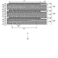
- FIG. 2 is a plan view showing a configuration example of the unit wrap unit 30 in the present embodiment, and is an enlarged view of the joint region 23 shown in FIG.
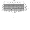
- FIG. 3 is an enlarged plan view showing one unit lap unit 30 of FIG.
- FIG. 4 is a plan view showing the flow of magnetic flux in the unit wrap unit 30 of the present embodiment
- FIG. 5 is a plan view showing the flow of magnetic flux in the conventional step wrap structure.
- the wound iron core 20 has a rectangular shape, it may have an annular shape, an elliptical shape, or an oval shape.
- the wound iron core 20 is formed in a rectangular shape in a plan view by laminating a plurality of long magnetic blocks.
- a winding 11 on the input side and a winding 12 on the output side are mounted on the two opposite sides 21 and 22 (legs) of the winding iron core 20, respectively, and when an alternating current is passed through the winding 11, a fluctuating magnetic field is applied. Is generated, and the winding 12 forms a transformer that is converted into an electric current again and output.
- the magnetic block of the wound iron core 20 is formed by laminating a plurality of layers of soft magnetic alloy strips.
- the magnetic block is wound once to form a unit layer, and the unit wrap unit 30 is formed by laminating a plurality of unit layers.
- the unit lap unit 30 includes a step lap unit unit 40 and an overlap unit unit 50. Both ends of each unit layer in the unit wrap unit 30 in the longitudinal direction are abutted against each other in the step wrap unit portion 40 and overlapped in the overlap unit portion 50 in the joint region 23.
- the soft magnetic alloy strip constituting the magnetic block for example, silicon steel, Fe-based amorphous alloy strip, etc. are used. Further, as the soft magnetic alloy strip, an Fe-based nanocrystal alloy strip having at least a part of the structure having a nanocrystal structure may be used.
- the unit wrap unit 30 is laminated in three layers from the inside to the outside (from the lower side to the upper side in FIG. 2) in the joint region 23.
- Each unit wrap unit 30 includes a step wrap unit portion 40 and an overlap unit portion 50 laminated on the outer side (upper side in FIG. 2).
- the unit wrap unit 30 can also be defined as an overlap unit portion 50 and a step wrap unit portion 40 laminated on the outer side thereof. That is, the step wrap unit portion 40 and the overlap unit portion 50 are alternately laminated.
- the step wrap unit portion 40 is formed by laminating seven unit layers 41, 42, 43, 44, 45, 46, 47 from the inside to the outside of the joining region 23.
- Each of these unit layers is formed by winding a magnetic block once, and includes a butt portion in which both end portions are butted against each other at a predetermined interval. In other words, in the abutting portion, both ends of the unit layer face each other at a predetermined interval.
- the number of laminated unit layers can be arbitrarily set according to the length of the bonding region 23, the thickness of the magnetic block, and the like.
- the abutting portions 41a, 42a, 43a, 44a, 45a, 46a, 47a of the seven unit layers 41, 42, 43, 44, 45, 46, 47 respectively have a winding direction of the magnetic block.
- the outer abutment portion is arranged on the right side (right side in FIG. 3).
- the positions of the butt portions of the respective magnetic blocks in the longitudinal direction are sequentially deviated by a certain dimension (deviation amount D) to the right side with respect to the butt portions of the magnetic blocks adjacent to the inside.
- the abutting portions 41a, 42a, 43a, 44a, 45a, 46a, 47a are sequentially arranged so as to be displaced via the deviation amount D in the longitudinal direction.
- the butt region A2 from the leftmost butt portion 41a to the rightmost butt portion 47a is set to a length L2.
- the deviation amount D is preferably the same as or larger than the thickness T of the magnetic blocks, which makes it possible to prevent the magnetic flux flowing through the two adjacent magnetic blocks from concentrating.
- the overlap unit portion 50 is formed by winding a magnetic block 51 around the outer surface of the unit layer 47, which is the outermost layer of the step wrap unit portion 40, and laminating one layer.
- the other end 53 is overlapped on the outer surface of one end 52 in the longitudinal direction of the magnetic block 51, whereby an overlapping portion is formed.
- the overlapping region A1 in which the overlapping portion is formed is set to a length L1 in the longitudinal direction of the magnetic block 51.
- the overlapping region A1 is set so as to overlap the abutting region A2 in the longitudinal direction of the magnetic block 51 (longitudinal direction of each unit layer of the step wrap unit portion 40).
- the midpoint of the overlapping region A1 and the midpoint of the abutting region A2 substantially coincide with each other, and this midpoint is located on a straight line C extending along the stacking direction. ..
- the total length L1 of the overlapping region A1 is set longer than the total length L2 of the abutting region A2. Further, the left and right ends of the overlapping region A1 are positioned so as to protrude outward in the longitudinal direction from the left and right ends of the abutting region A2 corresponding to each other. Therefore, when viewed from the upper side in the stacking direction (vertical direction in FIG. 3), the overlapping region A1 covers the entire abutting region A2. As a result, as shown in FIG. 4, the magnetic flux flowing through the unit layer 47, which is the outermost layer of the step wrap unit portion 40, and the magnetic flux flowing through the magnetic block 51 of the overlap unit portion 50 are prevented from being concentrated. Can be done.
- the magnetic fluxes F41, F42, F43, F44, F45, F46, F47, and F51 flowing through the step wrap unit portion 40 and the overlap unit portion 50 are shown by broken lines.
- the magnetic flux F41 causes the magnetic flux flowing in the unit layer 41 to flow on the unit layer 42 side in the range corresponding to the abutting portion 41a, and then returns to the unit layer 41.
- the magnetic fluxes F42 to F47 also flow through the outer unit layer in the range corresponding to the abutting portion while flowing through the unit layers 42 to 47, and then return to the original unit layer.
- the magnetic flux F51 flowing through the magnetic block 51 flows from the inside to the outside magnetic block in the overlapping region A1. Due to such a flow of magnetic flux, it is possible to prevent the magnetic fluxes F41, F42, F43, F44, F45, F46, F47, and F51 from overlapping each other.
- the left and right ends of the overlapping area A1 are outside the left and right ends of the matching area A2. Since the amount of deviation to the unit layer 47 is the same, the balance between the flow of magnetic flux from the unit layer 47 to the magnetic block 51 and the flow of magnetic flux returning from the magnetic block 51 to the unit layer 47 is improved, and the concentration of magnetic flux is effective. And it can be surely realized.
- the amount of deviation (protrusion amount) from each of the left and right ends of the overlap region A1 to the left and right ends of the abutting region A2 is equal to or larger than the thickness T of the magnetic block, the magnetic flux from 47 to the magnetic block 51 is generated. This is preferable because it facilitates the flow and the magnetic flux easily returns from the magnetic block 51 to 47.
- the configuration of the embodiment is as follows. Inner diameter of wound iron core 20, etc. (see Fig. 1) Major axis L11: 120 mm Minor diameter L12: 60 mm The length of the straight portion of the minor axis L12 corresponding to the overlapping region A1 L13: 48 mm Radius of curvature of corner C11: 6 mm
- Magnetic block The magnetic block of the step wrap unit portion 40 and the magnetic block of the overlap unit portion 50 are made of the same material and have the same thickness T, and are formed by laminating eight thin bands. There is.
- Step wrap unit unit 40 The seven-layer magnetic block includes abutting portions 41a, 42a, 43a, 44a, 45a, 46a, and 47a, respectively.
- Amount of deviation D in the longitudinal direction of the butt portion D 5.1 mm
- Length in the longitudinal direction of the butt part 1.0 mm
- Butt area length L2 37.6 mm
- Overlapping area A1 57.5 mm Except for overlapping area A1: 51.0 mm Further, the thickness of the two opposite sides 21 and 22 (legs) of the wound iron core 20 is 51.0 mm, which is the same as the total thickness other than the overlapping region A1.
- the space factor in the thickness direction (stacking direction) of the magnetic block is 85%
- the total thickness and the thicknesses of the two sides 21 and 22 have the following numerical values.
- Thickness of two opposite sides 21 and 22 of the wound iron core 20 60.0 mm
- the major axis L21 when the joint region 23 as described above was used was 247.6 mm.
- the wound iron core 20 having the above configuration was prepared from the Fe-based nanocrystalline alloy strip, and the length L1 of the overlapping region A1 of the unit wrap unit 30 was 44 mm, and the length L2 of the butt region A2 was 38 mm (that is,).
- the core loss of the wound iron core 20 (which satisfies L1> L2 + 2T) at 50 Hz and 1.5 T was measured and found to be 0.35 W / kg.
- the core loss of the wound iron core 20 at 50 Hz and 1.5 T was measured and found to be 0.40 W / kg. From this, it can be seen that the core loss can be reduced by satisfying L1> L2 + 2T when the total length of the overlapping region A1 in the longitudinal direction is L1 and the total length of the abutting region A2 in the longitudinal direction is L2.
- FIG. 6 is a plan view showing a schematic configuration of magnetic blocks laminated in the joint region of Comparative Example 2.
- the magnetic blocks 241, 242, 243, and 244 shown in FIG. 6 one end in the longitudinal direction overlaps the other end, respectively.
- one end 241a overlaps the other end 241b
- one end 242a overlaps the other end 242b
- the third magnetic block 243 one end 243a overlaps the other end 243b
- the fourth magnetic block 244a overlaps the other end 244b.
- the unit lap unit 240 is formed by such magnetic blocks 241 and 242, 243 and 244.
- Comparative Example 2 The configuration of Comparative Example 2 is as follows. (1) Unit lap unit 240 Number of layers of magnetic block 4 Total thickness: Overlapping area A10 2.5 mm (5 layers) Area other than the overlapping area A10 2.0 mm (4 layers) Distance between two magnetic blocks adjacent to each other in the stacking direction in the longitudinal direction D10: 5.3 mm The amount of deviation D11: 5.3 mm in the longitudinal direction of the distance D10 between two magnetic blocks adjacent to each other in the stacking direction.
- Magnetic block It is composed of eight thin bands laminated together.
- the outer two-layer magnetic block has three layers of magnetic blocks laminated in the overlapping region A10, and the thickness thereof is 1.5 mm in the overlapping region A10. It is 1.0 mm except for the mating area A10. Therefore, the total thickness is as follows. Overlapping area A10: 64.0 mm Other than the overlapping area A10: 51.0 mm Further, the thickness of the two opposite sides 21 and 22 (legs) of the wound iron core 20 is 51.0 mm, which is the same as the total thickness other than the overlapping region A10.
- the total thickness and the thicknesses of the two sides 21 and 22 (legs) have the following values.
- Overlapping area A10 75.3 mm
- overlapping area A10 60.0 mm
- Thickness of two opposite sides 21, 22 (legs) of the wound iron core 20 60.0 mm
- the shape of the inner diameter of the wound iron core 20 was the same as in the above embodiment, whereas the outer diameter and the like (see FIG. 1) are as follows. It was a street. Major axis L21: 255.3 mm Minor diameter L22: 180 mm Radius of curvature of corner C21: 66 mm
- the thicknesses of the two opposite sides 21 and 22 (legs) of the wound iron core 20 are the same (60.0 mm), but the total thickness in the overlapping region is occupied.
- the rate is set to 85%, it is 67.6 mm in the example (overlapping area A1) and 75.3 mm in the comparative example (overlapping area A10), which is significantly different depending on the configuration of the example. It was confirmed that the thickness can be suppressed.
- the wound iron core according to the present invention can prevent an increase in magnetic resistance due to a magnetic gap while suppressing an increase in the thickness of the wrap region provided with the overlap portion and the step wrap portion, resulting in core loss. It is useful in that it can be made smaller.
- Unit wrap unit 40 Step wrap unit 41, 42, 43, 44, 45, 46, 47 Unit layers 41a, 42a, 43a, 44a, 45a, 46a, 47a Butt 50 Overlap unit 51 Magnetic block 52, 53 Ends 141, 142, 143, 144, 145, 146, 147 Unit layer 240 Unit wrap unit 241 1st magnetic block 242 2nd magnetic block 243 3rd magnetic block 244 4th magnetic block 241a, 241b, 242a, 242b, 243a, 243b, 244a, 244b Ends A1, A10 Overlapping area A2 Butt area D Displacement amount D10 Interval D11 Displacement amount F41, F42, F43, F44, F45, F46, F47, F51 Magnetic flux F141, F142, F143, F144, F145, F146, F147 Magnetic flux L1 Length
Landscapes
- Engineering & Computer Science (AREA)
- Power Engineering (AREA)
- Manufacturing Cores, Coils, And Magnets (AREA)
- Coils Or Transformers For Communication (AREA)
Abstract
オーバーラップ部やステップラップ部を設けたラップ領域の厚みが厚くなることを抑えつつ、磁気ギャップによる磁気抵抗の増大を防ぐことができ、コアロスを小さくすることができる本発明に係る巻鉄心は、単位ラップユニットを突き合わせ領域と重ね合わせ領域が重複するように所定数積層して形成した巻鉄心であって、オーバーラップユニット部の重ね合わせ領域の長手方向の全長は、ステップラップユニット部の突き合わせ領域の長手方向の全長よりも大きく形成し、かつ、重ね合わせ領域が突き合わせ領域全体を積層方向から見たときに全て覆っている。
Description
本発明は、磁性材料の薄帯を複数積層してなる巻鉄心の構造に関する。
磁性材料を薄帯(薄い帯状体)とし、これを複数積層して巻鉄心に加工・成形した鉄心が、変圧器や変流器などに用いられている。このような巻鉄心は、従来の鉄心と比べると、小型化、軽量化を図ることができ、磁気特性においても有利であると考えられている。巻鉄心の積層構造としては、オーバーラップ構造とステップラップ構造が提案されている。
オーバーラップ構造は、磁性材料の薄帯を複数層積層し、薄帯ごとに、その両端部を互いに重ね合わせたオーバーラップ部を設けた構成としている(例えば特許文献1)。オーバーラップ構造では、薄帯を複数積層すると、各薄帯のオーバーラップ部が重ね合わせられるため、磁気ギャップが生じにくくなって磁気抵抗も小さくなることから、ヒステリシス損などのコアロスを小さくすることが可能となる。
ステップラップ構造は、オーバーラップ構造のように薄帯の両端部を互いに重ね合わせるのではなく、両端部を互いに突き合わせたステップラップ部を設けた構成としている。これにより、薄帯を複数層積層しても、オーバーラップ構造よりも厚みを薄くすることが可能となる(例えば特許文献2)。
しかしながら、オーバーラップ構造では、薄帯を積み重ねることによって、オーバーラップ部の重なり部分の厚さが厚くなり、巻鉄心全体の体積の小型化の妨げとなっていた。また、ステップラップ構造では、突き合わせ部の隙間に磁気ギャップが形成されてしまうため、この部分での磁気抵抗が大きくなって上記コアロスが大きくなるという欠点があった。これらの問題点は、特許文献2に記載の巻鉄心形静止誘導電器のように、ステップラップ構造の外側にオーバーラップ構造を積層した構成においても、それぞれの構造において同様に存在していた。
そこで本発明は、オーバーラップ部やステップラップ部を設けたラップ領域の厚みが厚くなることを抑えつつ、磁気ギャップによる磁気抵抗の増大を防ぐことができ、コアロスを小さくすることができる巻鉄心を提供することを目的としている。
上記課題を解決するために、本発明の巻鉄心は、複数層の軟磁性合金薄帯を積層することにより形成された長尺状の磁性ブロックを1周巻回し、所定の間隔を介して両端部同士を突き合わせた突き合わせ部を備えた単位層を形成し、磁性ブロックの巻回方向に沿った長手方向において突き合わせ部を一定の寸法ずつずらしながら単位層を複数層積層し、すべての突き合わせ部を含む突き合わせ領域を形成したステップラップユニット部と、端部が互いに重なる重複部を有するように磁性ブロックを巻回し、長手方向において重複部を突き合わせ領域に重複させるように積層して重ね合わせ領域を形成したオーバーラップユニット部とを備え、ステップラップユニット部とオーバーラップユニット部とを交互に積層した単位ラップユニットを形成し、単位ラップユニットを突き合わせ領域と重ね合わせ領域が重複するように積層して形成した巻鉄心において、オーバーラップユニット部の重ね合わせ領域の長手方向の全長は、ステップラップユニット部の突き合わせ領域の長手方向の全長よりも大きく形成し、かつ、重ね合わせ領域が突き合わせ領域全体を積層方向から見たときに全て覆っていることを特徴としている。
これにより、オーバーラップ部やステップラップ部を設けたラップ領域の厚みが厚くなることを抑えることができるだけでなく、外部への磁束の漏れを防止することができるため、ヒステリシス損などのコアロスを小さくすることができ、さらに、ステップラップユニット部の各磁性ブロックにおける磁束が流れやすくなり、磁気ギャップによる磁気抵抗の増大を防ぐことができる。
本発明の巻鉄心において、重ね合わせ領域の長手方向の中点と突き合わせ領域の長手方向の中点が略一致していることが好ましい。
これにより、突き合わせ領域が重ね合わせ領域によって確実に覆われるため、ステップラップユニット部の隣り合う磁性ブロックにおける磁束の流れが重なり合うことを抑えることができるため、磁束の流れを均一化できコアロスを小さくすることができる。
これにより、突き合わせ領域が重ね合わせ領域によって確実に覆われるため、ステップラップユニット部の隣り合う磁性ブロックにおける磁束の流れが重なり合うことを抑えることができるため、磁束の流れを均一化できコアロスを小さくすることができる。
本発明の巻鉄心において、オーバーラップユニット部を形成する磁性ブロックの厚さをTとしたときに、重ね合わせ領域の端部は、これに対応する突き合わせ領域の端部よりもTだけ突き合わせ領域の一端部よりも外側にはみ出していることが好ましい。さらに、重ね合わせ領域の長手方向の長さをL1とし、突き合わせ領域の長手方向の長さをL2としたときに、L1>L2+2Tの関係を有することが好ましい。
これにより、突き合わせ領域が重ね合わせ領域によって確実に覆われるとともに、ステップラップユニット部とオーバーラップユニット部との間の磁束の経路を確保できるため、隣り合う磁性ブロックにおける磁束の流れが重なり合うことを抑えることができる。
これにより、突き合わせ領域が重ね合わせ領域によって確実に覆われるとともに、ステップラップユニット部とオーバーラップユニット部との間の磁束の経路を確保できるため、隣り合う磁性ブロックにおける磁束の流れが重なり合うことを抑えることができる。
本発明の巻鉄心において、ステップラップユニット部において複数層積層された単位層の突き合わせ部の長手方向におけるずれ量Dは、厚さTに等しい又はそれよりも大きいことが好ましい。
これにより、ステップラップユニット部の各磁性ブロック間の磁束の経路が確保されるため、隣り合う磁性ブロックにおける磁束の流れが重なり合うことを抑えることができる。
これにより、ステップラップユニット部の各磁性ブロック間の磁束の経路が確保されるため、隣り合う磁性ブロックにおける磁束の流れが重なり合うことを抑えることができる。
本発明によると、オーバーラップ部やステップラップ部を設けたラップ領域の厚みが厚くなることを抑えつつ、磁気ギャップによる磁気抵抗の増大を防ぐことができ、コアロスを小さくすることができる巻鉄心を提供することができる。
以下、本発明の実施形態に係る巻鉄心について図面を参照しつつ詳しく説明する。本実施形態の巻鉄心20は、変圧器用の平面視矩形状のリング状巻線に適用した例であって、矩形状の巻鉄心20の角部は曲面状となっている。図1は、本実施形態に係る巻鉄心20の概略構成を示す平面図である。図2は、本実施形態における単位ラップユニット30の構成例を示す平面図であり、図1に示す接合領域23の拡大図である。図3は、図2の1つの単位ラップユニット30を拡大して示す平面図である。図4は、本実施形態の単位ラップユニット30における磁束の流れを示す平面図、図5は従来のステップラップ構造における磁束の流れを示す平面図である。なお、上記巻鉄心20は矩形状であるが、円環状であってもよいし、楕円状、長円状であってもよい。
図1に示すように、巻鉄心20は、長尺状の磁性ブロックを複数積層することにより平面視矩形状に形成される。この巻鉄心20には、対向する2辺21、22(脚部)に、入力側の巻線11と出力側の巻線12がそれぞれ装着され、巻線11に交流電流を流すと、変動磁場が発生し、巻線12で再び電流に変換されて出力されるトランスを形成する。
巻鉄心20の磁性ブロックは、軟磁性合金薄帯を複数層積層することにより形成される。磁性ブロックは、1周巻回されて単位層とされ、複数の単位層を積層することで単位ラップユニット30が形成される。単位ラップユニット30は、ステップラップユニット部40とオーバーラップユニット部50を備える。単位ラップユニット30における各単位層の長手方向の両端部は、接合領域23において、ステップラップユニット部40では互いに突き合わせられ、オーバーラップユニット部50では重ね合わせられる。
磁性ブロックを構成する軟磁性合金薄帯は、例えば、ケイ素鋼、Fe基アモルファス合金薄帯等が使用される。また、軟磁性合金薄帯は、組織の少なくとも一部がナノ結晶組織を有するFe基ナノ結晶合金薄帯を用いても良い。
図2に示す例では、単位ラップユニット30が、接合領域23において内側から外側へ(図2の下側から上側へ)、3層積層されている。それぞれの単位ラップユニット30は、ステップラップユニット部40と、その外側(図2における上側)に積層されたオーバーラップユニット部50とを備える。
ここで、単位ラップユニット30は、オーバーラップユニット部50と、その外側に積層したステップラップユニット部40として規定することもできる。すなわち、ステップラップユニット部40とオーバーラップユニット部50とを交互に積層した構成としている。
ここで、単位ラップユニット30は、オーバーラップユニット部50と、その外側に積層したステップラップユニット部40として規定することもできる。すなわち、ステップラップユニット部40とオーバーラップユニット部50とを交互に積層した構成としている。
ステップラップユニット部40は、7つの単位層41、42、43、44、45、46、47を接合領域23の内側から外側へ積層してなる。これらの単位層はそれぞれ、磁性ブロックを1周巻回したものであり、所定の間隔を介して両端部同士を互いに突き合わせた突き合わせ部を備える。別言すると、突き合わせ部では、単位層の両端部は、所定の間隔をあけて互いに対向している。単位層の積層数は、接合領域23の長さ、磁性ブロックの厚さなどに応じて任意に設定できる。
図3に示すように、7つの単位層41、42、43、44、45、46、47のそれぞれの突き合わせ部41a、42a、43a、44a、45a、46a、47aは、磁性ブロックの巻回方向に沿った長手方向(図3においては左右方向)において、外側の突き合わせ部ほど右側(図3の右側)に配置されている。それぞれの磁性ブロックの突き合わせ部の長手方向の位置は、内側に隣接する磁性ブロックの突き合わせ部に対して、右側に一定の寸法(ずれ量D)ずつ順にずれている。すなわち、突き合わせ部41a、42a、43a、44a、45a、46a、47aは、長手方向においてずれ量Dを介してずらして順に配置されている。長手方向において、最も左側の突き合わせ部41aから最も右側の突き合わせ部47aまでの突き合わせ領域A2は、長さL2に設定されている。上記ずれ量Dは、磁性ブロックの厚みTと同一又はこれより大きいことが好ましく、これにより、隣り合う2つの磁性ブロックを流れる磁束が集中してしまうことを抑えることが可能となる。
オーバーラップユニット部50は、ステップラップユニット部40の最外層である単位層47の外側面上に、磁性ブロック51を一周巻回し、1層積層させたものである。この磁性ブロック51の長手方向の一方の端部52の外側面上には、他方の端部53を重ねられ、これにより重複部が形成される。図3に示すように、重複部が形成された重ね合わせ領域A1は、磁性ブロック51の長手方向において、長さL1に設定されている。この重ね合わせ領域A1は、磁性ブロック51の長手方向(ステップラップユニット部40の各単位層の長手方向)において、突き合わせ領域A2と重なるように設定されている。さらに、磁性ブロック51の長手方向において、重ね合わせ領域A1の中点と突き合わせ領域A2の中点は略一致しており、この中点は、積層方向に沿って延びる直線C上に位置している。
図3に示すように、磁性ブロック51の長手方向において、重ね合わせ領域A1の全長L1は突き合わせ領域A2の全長L2よりも長く設定されている。さらに、重ね合わせ領域A1の左右両端は、それぞれに対応する、突き合わせ領域A2の左右両端よりも、長手方向の外側にそれぞれがはみだすように位置している。このため、積層方向(図3における上下方向)の上側から見て、重ね合わせ領域A1が突き合わせ領域A2の全体を覆っている。これにより、図4に示すように、ステップラップユニット部40の最外層である単位層47を流れる磁束と、オーバーラップユニット部50の磁性ブロック51を流れる磁束とが集中してしまうことを抑えることができる。
図4においては、ステップラップユニット部40とオーバーラップユニット部50を流れる磁束F41、F42、F43、F44、F45、F46、F47、F51を破線で示している。図4に示すように、磁束F41は、単位層41内を流れる磁束が、突き合わせ部41aに対応する範囲では単位層42側を流れ、その後に単位層41内へもどる。同様に、磁束F42~F47についても、単位層42~47を流れる途中で突き合わせ部に対応する範囲では外側の単位層を流れ、その後に元の単位層へもどる。磁性ブロック51を流れる磁束F51は、重ね合わせ領域A1において内側から外側の磁性ブロックへ流れる。このような磁束の流れにより、磁束F41、F42、F43、F44、F45、F46、F47、F51が互いに重なってしまうことを抑えることができる。
これに対して、図5に示す従来の構成においては、オーバーラップユニット部50が設けられていないため、最も外側の単位層147を流れる磁束F147と、その内側の単位層146から流れてきた磁束F146とが重なってしまう。これは、より内側の単位層141、142、143、144、145、146における磁束F141、F142、F143、F144、F145、F146についても同様である。
また、本実施形態において、重ね合わせ領域A1の中点と突き合わせ領域A2の中点とが一致しているため、長手方向において、突き合わせ領域A2の左右両端に対する重ね合わせ領域A1の左右両端それぞれから外側へのずれ量が同一となることから、単位層47から磁性ブロック51への磁束の流れと、磁性ブロック51から単位層47へもどる磁束の流れとのバランスがよくなり、磁束の集中を効果的かつ確実に実現することができる。
突き合わせ領域A2の左右両端に対する重ね合わせ領域A1の左右両端それぞれから外側へのずれ量(はみ出し量)を、磁性ブロックの厚みTと同一又はそれよりも大きくすると、47から磁性ブロック51への磁束が流れやすくなるとともに、磁性ブロック51から47へ磁束がもどりやすくなるため好ましい。
さらに、図3に示すように、重ね合わせ領域A1の長手方向の全長をL1とし、突き合わせ領域A2の長手方向の全長の長さをL2としたときに、上記ずれ量(はみ出し量)に関して次式(1)に示す関係が成り立つと、外部への磁束の漏れを防止でき、磁束の集中を効果的かつ確実に実現する点において好ましい。
L1>L2+2T (1)
L1>L2+2T (1)
(実施例)
実施例の構成は次の通りである。
巻鉄心20の内径等(図1参照)
長径L11:120mm
短径L12: 60mm
短径L12のうち重ね合わせ領域A1に対応する直線部分の長さL13:48mm
角部C11の曲率半径:6mm
実施例の構成は次の通りである。
巻鉄心20の内径等(図1参照)
長径L11:120mm
短径L12: 60mm
短径L12のうち重ね合わせ領域A1に対応する直線部分の長さL13:48mm
角部C11の曲率半径:6mm
巻鉄心20の外径等(図1参照)
短径L22:180mm
角部C21の曲率半径:66mm
(1)単位ラップユニット30
ステップラップユニット部40の磁性ブロック:層数7、総厚3.5mm
オーバーラップユニット部50の磁性ブロック:重ね合わせ領域A1では2層(総厚1.0mm)、重ね合わせ領域A1以外では1層(厚み0.5mm)
全体の厚み:重ね合わせ領域A1では4.5mm、重ね合わせ領域A1以外では4.0mm
磁性ブロックの総数(ステップ数):重ね合わせ領域A1では9、重ね合わせ領域A1以外では8
重ね合わせ領域A1の長さL1:48mm
短径L22:180mm
角部C21の曲率半径:66mm
(1)単位ラップユニット30
ステップラップユニット部40の磁性ブロック:層数7、総厚3.5mm
オーバーラップユニット部50の磁性ブロック:重ね合わせ領域A1では2層(総厚1.0mm)、重ね合わせ領域A1以外では1層(厚み0.5mm)
全体の厚み:重ね合わせ領域A1では4.5mm、重ね合わせ領域A1以外では4.0mm
磁性ブロックの総数(ステップ数):重ね合わせ領域A1では9、重ね合わせ領域A1以外では8
重ね合わせ領域A1の長さL1:48mm
(2)磁性ブロック
ステップラップユニット部40の磁性ブロックとオーバーラップユニット部50の磁性ブロックは同一の材料で同一の厚みTで形成されており、8層の薄帯を積層することによって構成されている。
ステップラップユニット部40の磁性ブロックとオーバーラップユニット部50の磁性ブロックは同一の材料で同一の厚みTで形成されており、8層の薄帯を積層することによって構成されている。
(3)ステップラップユニット部40
7層の磁性ブロックが突き合わせ部41a、42a、43a、44a、45a、46a、47aをそれぞれ備える。
突き合わせ部の長手方向におけるずれ量D:5.1mm
突き合わせ部の長手方向における長さ:1.0mm
突き合わせ領域の長さL2:37.6mm
7層の磁性ブロックが突き合わせ部41a、42a、43a、44a、45a、46a、47aをそれぞれ備える。
突き合わせ部の長手方向におけるずれ量D:5.1mm
突き合わせ部の長手方向における長さ:1.0mm
突き合わせ領域の長さL2:37.6mm
(4)全体構成
単位ラップユニット30を内側から外側へ12ユニット積層し、その外側に、5層の磁性ブロックからなるステップラップユニット部40(厚み2.5mm)を積層し、さらにその外側に、オーバーラップユニット部50を形成した。最も外側のオーバーラップユニット部50の磁性ブロックは、単位ラップユニット30における磁性ブロックと同様に、重ね合わせ領域A1において2層の磁性ブロックを積層しており、その厚みは、重ね合わせ領域A1では1.0mm、重ね合わせ領域A1以外では0.5mmである。
したがって総厚は次の通りである。
重ね合わせ領域A1 :57.5mm
重ね合わせ領域A1以外:51.0mm
また、巻鉄心20の対向する2辺21、22(脚部)の厚みは、重ね合わせ領域A1以外の総厚と同一の51.0mmとなる。
ここで、磁性ブロックの厚み方向(積層方向)における占積率を85%とすると、上記総厚及び上記2辺21、22の厚みは次の数値となる。
重ね合わせ領域A1 :67.6mm
重ね合わせ領域A1以外:60.0mm
巻鉄心20の対向する2辺21、22の厚み:60.0mm
上記のような接合領域23とした場合の長径L21は247.6mmであった。
単位ラップユニット30を内側から外側へ12ユニット積層し、その外側に、5層の磁性ブロックからなるステップラップユニット部40(厚み2.5mm)を積層し、さらにその外側に、オーバーラップユニット部50を形成した。最も外側のオーバーラップユニット部50の磁性ブロックは、単位ラップユニット30における磁性ブロックと同様に、重ね合わせ領域A1において2層の磁性ブロックを積層しており、その厚みは、重ね合わせ領域A1では1.0mm、重ね合わせ領域A1以外では0.5mmである。
したがって総厚は次の通りである。
重ね合わせ領域A1 :57.5mm
重ね合わせ領域A1以外:51.0mm
また、巻鉄心20の対向する2辺21、22(脚部)の厚みは、重ね合わせ領域A1以外の総厚と同一の51.0mmとなる。
ここで、磁性ブロックの厚み方向(積層方向)における占積率を85%とすると、上記総厚及び上記2辺21、22の厚みは次の数値となる。
重ね合わせ領域A1 :67.6mm
重ね合わせ領域A1以外:60.0mm
巻鉄心20の対向する2辺21、22の厚み:60.0mm
上記のような接合領域23とした場合の長径L21は247.6mmであった。
(実験例)
(実施例)
Fe基ナノ結晶合金薄帯で上記構成の巻鉄心20を作成し、上記の単位ラップユニット30の重ね合わせ領域A1の長さL1を44mm、突き合わせ領域A2の長さL2を38mmとした(すなわち、L1>L2+2Tを満たす)巻鉄心20の50Hz、1.5Tにおけるコアロスを測定したところ、0.35W/kgであった。
(実施例)
Fe基ナノ結晶合金薄帯で上記構成の巻鉄心20を作成し、上記の単位ラップユニット30の重ね合わせ領域A1の長さL1を44mm、突き合わせ領域A2の長さL2を38mmとした(すなわち、L1>L2+2Tを満たす)巻鉄心20の50Hz、1.5Tにおけるコアロスを測定したところ、0.35W/kgであった。
(比較例1)
Fe基ナノ結晶合金薄帯で上記構成の巻鉄心20を作成し、上記単位ラップユニット30の重ね合わせ領域A1の長さL1を39mm、突き合わせ領域A2の長さL2を38mm(すなわち、L1=L2+2Tとした)巻鉄心20の50Hz、1.5Tにおけるコアロスを測定したところ、0.40W/kgであった。
このことから、重ね合わせ領域A1の長手方向の全長をL1とし、突き合わせ領域A2の長手方向の全長の長さをL2としたときに、L1>L2+2Tを満たすことで、コアロスを低減できることがわかる。
Fe基ナノ結晶合金薄帯で上記構成の巻鉄心20を作成し、上記単位ラップユニット30の重ね合わせ領域A1の長さL1を39mm、突き合わせ領域A2の長さL2を38mm(すなわち、L1=L2+2Tとした)巻鉄心20の50Hz、1.5Tにおけるコアロスを測定したところ、0.40W/kgであった。
このことから、重ね合わせ領域A1の長手方向の全長をL1とし、突き合わせ領域A2の長手方向の全長の長さをL2としたときに、L1>L2+2Tを満たすことで、コアロスを低減できることがわかる。
(比較例2)
図6は、比較例2の接合領域において積層された磁性ブロックの概略構成を示す平面図である。図6に示す磁性ブロック241、242、243、244においては、それぞれ、長手方向の一方の端部が他方の端部上に重なっている。具体的には、第1磁性ブロック241では、一方の端部241aが他方の端部241b上に重なっており、第2磁性ブロック242では、一方の端部242aが他方の端部242b上に重なっており、第3磁性ブロック243では、一方の端部243aが他方の端部243b上に重なっており、第4磁性ブロック244では、一方の端部244aが他方の端部244b上に重なっている。このような磁性ブロック241、242、243、244によって単位ラップユニット240が形成される。
図6は、比較例2の接合領域において積層された磁性ブロックの概略構成を示す平面図である。図6に示す磁性ブロック241、242、243、244においては、それぞれ、長手方向の一方の端部が他方の端部上に重なっている。具体的には、第1磁性ブロック241では、一方の端部241aが他方の端部241b上に重なっており、第2磁性ブロック242では、一方の端部242aが他方の端部242b上に重なっており、第3磁性ブロック243では、一方の端部243aが他方の端部243b上に重なっており、第4磁性ブロック244では、一方の端部244aが他方の端部244b上に重なっている。このような磁性ブロック241、242、243、244によって単位ラップユニット240が形成される。
比較例2の構成は次の通りである。
(1)単位ラップユニット240
磁性ブロックの層数4
総厚:重ね合わせ領域A10 2.5mm(5層)
重ね合わせ領域A10以外の領域 2.0mm(4層)
積層方向に隣り合う2つの磁性ブロックの長手方向における間隔D10:5.3mm
積層方向に隣り合う2つの磁性ブロックの間隔D10の、長手方向におけるずれ量D11:5.3mm
(1)単位ラップユニット240
磁性ブロックの層数4
総厚:重ね合わせ領域A10 2.5mm(5層)
重ね合わせ領域A10以外の領域 2.0mm(4層)
積層方向に隣り合う2つの磁性ブロックの長手方向における間隔D10:5.3mm
積層方向に隣り合う2つの磁性ブロックの間隔D10の、長手方向におけるずれ量D11:5.3mm
(2)磁性ブロック
8層の薄帯を積層することによって構成されている。
8層の薄帯を積層することによって構成されている。
(3)全体構成
単位ラップユニット240を内側から外側へ25ユニット積層し、その外側に、2層の磁性ブロックを積層して巻鉄心20を形成した。外側の2層の磁性ブロックは、単位ラップユニット240における磁性ブロックと同様に、重ね合わせ領域A10において3層の磁性ブロックを積層しており、その厚みは、重ね合わせ領域A10では1.5mm、重ね合わせ領域A10以外では1.0mmである。
したがって総厚は次の通りである。
重ね合わせ領域A10 :64.0mm
重ね合わせ領域A10以外:51.0mm
また、巻鉄心20の対向する2辺21、22(脚部)の厚みは、重ね合わせ領域A10以外の総厚と同一の51.0mmとなる。
さらに、磁性ブロックの厚み方向(積層方向)における占積率を85%とすると、上記総厚及び上記2辺21、22(脚部)の厚みは次の数値となる。
重ね合わせ領域A10 :75.3mm
重ね合わせ領域A10以外:60.0mm
巻鉄心20の対向する2辺21、22(脚部)の厚み:60.0mm
単位ラップユニット240を内側から外側へ25ユニット積層し、その外側に、2層の磁性ブロックを積層して巻鉄心20を形成した。外側の2層の磁性ブロックは、単位ラップユニット240における磁性ブロックと同様に、重ね合わせ領域A10において3層の磁性ブロックを積層しており、その厚みは、重ね合わせ領域A10では1.5mm、重ね合わせ領域A10以外では1.0mmである。
したがって総厚は次の通りである。
重ね合わせ領域A10 :64.0mm
重ね合わせ領域A10以外:51.0mm
また、巻鉄心20の対向する2辺21、22(脚部)の厚みは、重ね合わせ領域A10以外の総厚と同一の51.0mmとなる。
さらに、磁性ブロックの厚み方向(積層方向)における占積率を85%とすると、上記総厚及び上記2辺21、22(脚部)の厚みは次の数値となる。
重ね合わせ領域A10 :75.3mm
重ね合わせ領域A10以外:60.0mm
巻鉄心20の対向する2辺21、22(脚部)の厚み:60.0mm
巻鉄心20の内径等の形状(長径L11、短径L12、L13、角部C11の曲率半径)は上記実施例と同一であったのに対して、外径等(図1参照)については次の通りであった。
長径L21:255.3mm
短径L22:180mm
角部C21の曲率半径:66mm
長径L21:255.3mm
短径L22:180mm
角部C21の曲率半径:66mm
以上のように、実施例と比較例では、巻鉄心20の対向する2辺21、22(脚部)の厚みを同一(60.0mm)としたが、重ね合わせ領域における総厚は、占積率85%に設定した場合、実施例(重ね合わせ領域A1)では67.6mmであるのに対して比較例(重ね合わせ領域A10)では75.3mmとなっており、実施例の構成によって大幅に厚みを抑えることができることが確認できた。
本発明について上記実施形態を参照しつつ説明したが、本発明は上記実施形態に限定されるものではなく、改良の目的又は本発明の思想の範囲内において改良又は変更が可能である。
本発明について上記実施形態を参照しつつ説明したが、本発明は上記実施形態に限定されるものではなく、改良の目的又は本発明の思想の範囲内において改良又は変更が可能である。
以上のように、本発明に係る巻鉄心は、オーバーラップ部やステップラップ部を設けたラップ領域の厚みが厚くなることを抑えつつ、磁気ギャップによる磁気抵抗の増大を防ぐことができ、コアロスを小さくすることができる点で有用である。
11 入力側の巻線
12 出力側の巻線
20 巻鉄心
21、22 対向する2辺(脚部)
23 接合領域
30 単位ラップユニット
40 ステップラップユニット部
41、42、43、44、45、46、47 単位層
41a、42a、43a、44a、45a、46a、47a 突き合わせ部
50 オーバーラップユニット部
51 磁性ブロック
52、53 端部
141、142、143、144、145、146、147 単位層
240 単位ラップユニット
241 第1磁性ブロック
242 第2磁性ブロック
243 第3磁性ブロック
244 第4磁性ブロック
241a、241b、242a、242b、243a、243b、244a、244b 端部
A1、A10 重ね合わせ領域
A2 突き合わせ領域
D ずれ量
D10 間隔
D11 ずれ量
F41、F42、F43、F44、F45、F46、F47、F51 磁束
F141、F142、F143、F144、F145、F146、F147 磁束
L1 重ね合わせ領域の長さ
L2 突き合わせ領域の長さ
T 磁性ブロックの厚み
12 出力側の巻線
20 巻鉄心
21、22 対向する2辺(脚部)
23 接合領域
30 単位ラップユニット
40 ステップラップユニット部
41、42、43、44、45、46、47 単位層
41a、42a、43a、44a、45a、46a、47a 突き合わせ部
50 オーバーラップユニット部
51 磁性ブロック
52、53 端部
141、142、143、144、145、146、147 単位層
240 単位ラップユニット
241 第1磁性ブロック
242 第2磁性ブロック
243 第3磁性ブロック
244 第4磁性ブロック
241a、241b、242a、242b、243a、243b、244a、244b 端部
A1、A10 重ね合わせ領域
A2 突き合わせ領域
D ずれ量
D10 間隔
D11 ずれ量
F41、F42、F43、F44、F45、F46、F47、F51 磁束
F141、F142、F143、F144、F145、F146、F147 磁束
L1 重ね合わせ領域の長さ
L2 突き合わせ領域の長さ
T 磁性ブロックの厚み
Claims (5)
- 複数層の軟磁性合金薄帯を積層することにより形成された長尺状の磁性ブロックを1周巻回し、所定の間隔を介して両端部同士を突き合わせた突き合わせ部を備えた単位層を形成し、前記磁性ブロックの巻回方向に沿った長手方向において前記突き合わせ部を一定の寸法ずつずらしながら前記単位層を複数層積層し、すべての前記突き合わせ部を含む突き合わせ領域を形成したステップラップユニット部と、
端部が互いに重なる重複部を有するように前記磁性ブロックを巻回し、前記長手方向において前記重複部を前記突き合わせ領域に重複させるように積層して重ね合わせ領域を形成したオーバーラップユニット部とを備え、
前記ステップラップユニット部と前記オーバーラップユニット部とを交互に積層した単位ラップユニットを形成し、
前記単位ラップユニットを前記突き合わせ領域と前記重ね合わせ領域が重複するように積層して形成した巻鉄心において、前記オーバーラップユニット部の前記重ね合わせ領域の前記長手方向の全長は、前記ステップラップユニット部の前記突き合わせ領域の前記長手方向の全長よりも大きく形成し、かつ、前記重ね合わせ領域が前記突き合わせ領域の全体を積層方向から見たときに全て覆っていることを特徴とする巻鉄心。 - 前記重ね合わせ領域の前記長手方向の中点と前記突き合わせ領域の前記長手方向の中点が略一致している請求項1に記載の巻鉄心。
- 前記オーバーラップユニット部を形成する前記磁性ブロックの厚さをTとしたときに、前記重ね合わせ領域の端部は、これに対応する前記突き合わせ領域の端部よりもTだけ前記突き合わせ領域の端部よりも外側にはみ出している請求項1又は請求項2に記載の巻鉄心。
- 前記重ね合わせ領域の前記長手方向の長さをL1とし、前記突き合わせ領域の前記長手方向の長さをL2としたときに、L1>L2+2Tの関係を有する請求項3に記載の巻鉄心。
- 前記ステップラップユニット部において複数層積層された前記単位層の前記突き合わせ部の前記長手方向におけるずれ量Dは、前記厚さTに等しい又はそれよりも大きい請求項3又は請求項4に記載の巻鉄心。
Priority Applications (1)
| Application Number | Priority Date | Filing Date | Title |
|---|---|---|---|
| CN202090000633.1U CN216648006U (zh) | 2019-06-04 | 2020-05-29 | 卷绕铁心 |
Applications Claiming Priority (2)
| Application Number | Priority Date | Filing Date | Title |
|---|---|---|---|
| JP2019104634 | 2019-06-04 | ||
| JP2019-104634 | 2019-06-04 |
Publications (1)
| Publication Number | Publication Date |
|---|---|
| WO2020246388A1 true WO2020246388A1 (ja) | 2020-12-10 |
Family
ID=73652275
Family Applications (1)
| Application Number | Title | Priority Date | Filing Date |
|---|---|---|---|
| PCT/JP2020/021355 Ceased WO2020246388A1 (ja) | 2019-06-04 | 2020-05-29 | 巻鉄心 |
Country Status (2)
| Country | Link |
|---|---|
| CN (1) | CN216648006U (ja) |
| WO (1) | WO2020246388A1 (ja) |
Cited By (3)
| Publication number | Priority date | Publication date | Assignee | Title |
|---|---|---|---|---|
| WO2023249052A1 (ja) * | 2022-06-22 | 2023-12-28 | 日本製鉄株式会社 | 巻鉄心 |
| JP7582566B1 (ja) * | 2023-07-25 | 2024-11-13 | Jfeスチール株式会社 | 巻鉄心および巻鉄心変圧器 |
| EP4546381A4 (en) * | 2022-06-22 | 2025-10-22 | Nippon Steel Corp | WOUND CORE |
Citations (4)
| Publication number | Priority date | Publication date | Assignee | Title |
|---|---|---|---|---|
| JPS59175110A (ja) * | 1983-03-24 | 1984-10-03 | Hitachi Ltd | 巻鉄心形静止誘導電器 |
| JPS63205904A (ja) * | 1987-02-23 | 1988-08-25 | Tokyo Electric Power Co Inc:The | 静止誘導電器の製造方法 |
| JPH0620849A (ja) * | 1992-07-03 | 1994-01-28 | Hitachi Ltd | アモルファス巻鉄心 |
| US20160196916A1 (en) * | 2013-09-03 | 2016-07-07 | Aem Cores Pty Ltd | Wound transformer core |
-
2020
- 2020-05-29 CN CN202090000633.1U patent/CN216648006U/zh active Active
- 2020-05-29 WO PCT/JP2020/021355 patent/WO2020246388A1/ja not_active Ceased
Patent Citations (4)
| Publication number | Priority date | Publication date | Assignee | Title |
|---|---|---|---|---|
| JPS59175110A (ja) * | 1983-03-24 | 1984-10-03 | Hitachi Ltd | 巻鉄心形静止誘導電器 |
| JPS63205904A (ja) * | 1987-02-23 | 1988-08-25 | Tokyo Electric Power Co Inc:The | 静止誘導電器の製造方法 |
| JPH0620849A (ja) * | 1992-07-03 | 1994-01-28 | Hitachi Ltd | アモルファス巻鉄心 |
| US20160196916A1 (en) * | 2013-09-03 | 2016-07-07 | Aem Cores Pty Ltd | Wound transformer core |
Cited By (6)
| Publication number | Priority date | Publication date | Assignee | Title |
|---|---|---|---|---|
| WO2023249052A1 (ja) * | 2022-06-22 | 2023-12-28 | 日本製鉄株式会社 | 巻鉄心 |
| JPWO2023249052A1 (ja) * | 2022-06-22 | 2023-12-28 | ||
| JP7572658B2 (ja) | 2022-06-22 | 2024-10-24 | 日本製鉄株式会社 | 巻鉄心 |
| EP4546381A4 (en) * | 2022-06-22 | 2025-10-22 | Nippon Steel Corp | WOUND CORE |
| JP7582566B1 (ja) * | 2023-07-25 | 2024-11-13 | Jfeスチール株式会社 | 巻鉄心および巻鉄心変圧器 |
| WO2025022719A1 (ja) * | 2023-07-25 | 2025-01-30 | Jfeスチール株式会社 | 巻鉄心および巻鉄心変圧器 |
Also Published As
| Publication number | Publication date |
|---|---|
| CN216648006U (zh) | 2022-05-31 |
Similar Documents
| Publication | Publication Date | Title |
|---|---|---|
| CN216648006U (zh) | 卷绕铁心 | |
| WO2020121691A1 (ja) | 静止誘導機器用鉄心及び静止誘導機器 | |
| JP3237671U (ja) | 巻鉄心 | |
| WO2020071460A1 (ja) | 巻鉄心 | |
| US7471183B2 (en) | Transformer | |
| US7557687B2 (en) | Magnetic core for electromagnetic apparatus and electromagnetic apparatus provided with magnetic core for electromagnetic apparatus | |
| US2698924A (en) | Three-phase split magnetic core | |
| JP5519550B2 (ja) | 分割コアおよびステータコア | |
| US20180204669A1 (en) | Stationary Induction Apparatus Core | |
| JP7150418B2 (ja) | 巻鉄心および巻鉄心の製造方法 | |
| CA1056925A (en) | Core lamination for shell-type cores, preferably for transformers | |
| JP5432078B2 (ja) | 変圧器 | |
| CN119480376A (zh) | 线圈部件 | |
| JPH0456441B2 (ja) | ||
| JP4249594B2 (ja) | 変圧器および変圧器の巻鉄心 | |
| US20230238166A1 (en) | Stationary Induction Electric Apparatus | |
| US3613229A (en) | Method of making transformer cores | |
| JP2006173449A (ja) | 変圧器 | |
| JPH04302110A (ja) | アモルファス鉄心変圧器 | |
| JP5425114B2 (ja) | アモルファス巻鉄心変圧器 | |
| JP4704670B2 (ja) | アモルファス巻鉄心変圧器 | |
| WO2016006314A1 (ja) | 巻鉄心および巻鉄心の製造方法 | |
| JPH07249537A (ja) | アモルファス巻鉄心およびその製造方法 | |
| JP2017054896A (ja) | 変圧器用鉄心、及びそれを用いた変圧器 | |
| JP2006351959A (ja) | リアクトル |
Legal Events
| Date | Code | Title | Description |
|---|---|---|---|
| 121 | Ep: the epo has been informed by wipo that ep was designated in this application |
Ref document number: 20818954 Country of ref document: EP Kind code of ref document: A1 |
|
| ENP | Entry into the national phase |
Ref document number: 2022600017 Country of ref document: JP Kind code of ref document: A |
|
| NENP | Non-entry into the national phase |
Ref country code: DE |
|
| 122 | Ep: pct application non-entry in european phase |
Ref document number: 20818954 Country of ref document: EP Kind code of ref document: A1 |