WO2020246264A1 - 測距センサ、信号処理方法、および、測距モジュール - Google Patents
測距センサ、信号処理方法、および、測距モジュール Download PDFInfo
- Publication number
- WO2020246264A1 WO2020246264A1 PCT/JP2020/020246 JP2020020246W WO2020246264A1 WO 2020246264 A1 WO2020246264 A1 WO 2020246264A1 JP 2020020246 W JP2020020246 W JP 2020020246W WO 2020246264 A1 WO2020246264 A1 WO 2020246264A1
- Authority
- WO
- WIPO (PCT)
- Prior art keywords
- detection process
- detection
- information
- light
- distance
- Prior art date
- Legal status (The legal status is an assumption and is not a legal conclusion. Google has not performed a legal analysis and makes no representation as to the accuracy of the status listed.)
- Ceased
Links
Images





Classifications
-
- H—ELECTRICITY
- H04—ELECTRIC COMMUNICATION TECHNIQUE
- H04M—TELEPHONIC COMMUNICATION
- H04M1/00—Substation equipment, e.g. for use by subscribers
- H04M1/72—Mobile telephones; Cordless telephones, i.e. devices for establishing wireless links to base stations without route selection
- H04M1/724—User interfaces specially adapted for cordless or mobile telephones
- H04M1/72403—User interfaces specially adapted for cordless or mobile telephones with means for local support of applications that increase the functionality
- H04M1/72409—User interfaces specially adapted for cordless or mobile telephones with means for local support of applications that increase the functionality by interfacing with external accessories
-
- G—PHYSICS
- G01—MEASURING; TESTING
- G01S—RADIO DIRECTION-FINDING; RADIO NAVIGATION; DETERMINING DISTANCE OR VELOCITY BY USE OF RADIO WAVES; LOCATING OR PRESENCE-DETECTING BY USE OF THE REFLECTION OR RERADIATION OF RADIO WAVES; ANALOGOUS ARRANGEMENTS USING OTHER WAVES
- G01S7/00—Details of systems according to groups G01S13/00, G01S15/00, G01S17/00
- G01S7/48—Details of systems according to groups G01S13/00, G01S15/00, G01S17/00 of systems according to group G01S17/00
- G01S7/491—Details of non-pulse systems
- G01S7/4912—Receivers
- G01S7/4913—Circuits for detection, sampling, integration or read-out
- G01S7/4914—Circuits for detection, sampling, integration or read-out of detector arrays, e.g. charge-transfer gates
-
- G—PHYSICS
- G01—MEASURING; TESTING
- G01S—RADIO DIRECTION-FINDING; RADIO NAVIGATION; DETERMINING DISTANCE OR VELOCITY BY USE OF RADIO WAVES; LOCATING OR PRESENCE-DETECTING BY USE OF THE REFLECTION OR RERADIATION OF RADIO WAVES; ANALOGOUS ARRANGEMENTS USING OTHER WAVES
- G01S7/00—Details of systems according to groups G01S13/00, G01S15/00, G01S17/00
- G01S7/48—Details of systems according to groups G01S13/00, G01S15/00, G01S17/00 of systems according to group G01S17/00
- G01S7/483—Details of pulse systems
- G01S7/486—Receivers
- G01S7/4861—Circuits for detection, sampling, integration or read-out
- G01S7/4863—Detector arrays, e.g. charge-transfer gates
-
- G—PHYSICS
- G01—MEASURING; TESTING
- G01S—RADIO DIRECTION-FINDING; RADIO NAVIGATION; DETERMINING DISTANCE OR VELOCITY BY USE OF RADIO WAVES; LOCATING OR PRESENCE-DETECTING BY USE OF THE REFLECTION OR RERADIATION OF RADIO WAVES; ANALOGOUS ARRANGEMENTS USING OTHER WAVES
- G01S17/00—Systems using the reflection or reradiation of electromagnetic waves other than radio waves, e.g. lidar systems
- G01S17/02—Systems using the reflection of electromagnetic waves other than radio waves
- G01S17/06—Systems determining position data of a target
- G01S17/08—Systems determining position data of a target for measuring distance only
-
- G—PHYSICS
- G01—MEASURING; TESTING
- G01S—RADIO DIRECTION-FINDING; RADIO NAVIGATION; DETERMINING DISTANCE OR VELOCITY BY USE OF RADIO WAVES; LOCATING OR PRESENCE-DETECTING BY USE OF THE REFLECTION OR RERADIATION OF RADIO WAVES; ANALOGOUS ARRANGEMENTS USING OTHER WAVES
- G01S17/00—Systems using the reflection or reradiation of electromagnetic waves other than radio waves, e.g. lidar systems
- G01S17/88—Lidar systems specially adapted for specific applications
- G01S17/89—Lidar systems specially adapted for specific applications for mapping or imaging
- G01S17/894—Three-dimensional [3D] imaging with simultaneous measurement of time-of-flight at a two-dimensional [2D] array of receiver pixels, e.g. time-of-flight cameras or flash lidar
-
- G—PHYSICS
- G01—MEASURING; TESTING
- G01S—RADIO DIRECTION-FINDING; RADIO NAVIGATION; DETERMINING DISTANCE OR VELOCITY BY USE OF RADIO WAVES; LOCATING OR PRESENCE-DETECTING BY USE OF THE REFLECTION OR RERADIATION OF RADIO WAVES; ANALOGOUS ARRANGEMENTS USING OTHER WAVES
- G01S7/00—Details of systems according to groups G01S13/00, G01S15/00, G01S17/00
- G01S7/48—Details of systems according to groups G01S13/00, G01S15/00, G01S17/00 of systems according to group G01S17/00
- G01S7/4802—Details of systems according to groups G01S13/00, G01S15/00, G01S17/00 of systems according to group G01S17/00 using analysis of echo signal for target characterisation; Target signature; Target cross-section
-
- G—PHYSICS
- G01—MEASURING; TESTING
- G01S—RADIO DIRECTION-FINDING; RADIO NAVIGATION; DETERMINING DISTANCE OR VELOCITY BY USE OF RADIO WAVES; LOCATING OR PRESENCE-DETECTING BY USE OF THE REFLECTION OR RERADIATION OF RADIO WAVES; ANALOGOUS ARRANGEMENTS USING OTHER WAVES
- G01S7/00—Details of systems according to groups G01S13/00, G01S15/00, G01S17/00
- G01S7/48—Details of systems according to groups G01S13/00, G01S15/00, G01S17/00 of systems according to group G01S17/00
- G01S7/483—Details of pulse systems
- G01S7/486—Receivers
- G01S7/4865—Time delay measurement, e.g. time-of-flight measurement, time of arrival measurement or determining the exact position of a peak
-
- H—ELECTRICITY
- H04—ELECTRIC COMMUNICATION TECHNIQUE
- H04B—TRANSMISSION
- H04B10/00—Transmission systems employing electromagnetic waves other than radio-waves, e.g. infrared, visible or ultraviolet light, or employing corpuscular radiation, e.g. quantum communication
- H04B10/50—Transmitters
-
- H—ELECTRICITY
- H04—ELECTRIC COMMUNICATION TECHNIQUE
- H04B—TRANSMISSION
- H04B10/00—Transmission systems employing electromagnetic waves other than radio-waves, e.g. infrared, visible or ultraviolet light, or employing corpuscular radiation, e.g. quantum communication
- H04B10/60—Receivers
-
- H—ELECTRICITY
- H04—ELECTRIC COMMUNICATION TECHNIQUE
- H04M—TELEPHONIC COMMUNICATION
- H04M1/00—Substation equipment, e.g. for use by subscribers
-
- H—ELECTRICITY
- H04—ELECTRIC COMMUNICATION TECHNIQUE
- H04M—TELEPHONIC COMMUNICATION
- H04M1/00—Substation equipment, e.g. for use by subscribers
- H04M1/72—Mobile telephones; Cordless telephones, i.e. devices for establishing wireless links to base stations without route selection
- H04M1/724—User interfaces specially adapted for cordless or mobile telephones
- H04M1/72448—User interfaces specially adapted for cordless or mobile telephones with means for adapting the functionality of the device according to specific conditions
- H04M1/72454—User interfaces specially adapted for cordless or mobile telephones with means for adapting the functionality of the device according to specific conditions according to context-related or environment-related conditions
Definitions
- the present technology relates to a distance measurement sensor, a signal processing method, and a distance measurement module, and in particular, a distance measurement sensor, a signal processing method, and a distance measurement that enable the distance measurement sensor to execute detection processing based on the distance measurement data.
- a distance measurement sensor a signal processing method
- a distance measurement module a distance measurement that enable the distance measurement sensor to execute detection processing based on the distance measurement data.
- a distance measuring module is mounted on a mobile terminal such as a so-called smartphone, which is a small information processing device having a communication function.
- the distance measuring method in the distance measuring module includes, for example, the Indirect ToF (Time of Flight) method and the Structured Light method.
- IndirectToF method light is emitted toward an object, the light reflected on the surface of the object is detected, and the distance to the object is calculated based on the measured value obtained by measuring the flight time of the light.
- the Structured Light method the distance to the object is calculated based on the image obtained by irradiating the object with pattern light and capturing the distortion of the pattern on the surface of the object.
- the Indirect ToF type ranging sensor has improved light receiving characteristics by adopting a back-illuminated type (see, for example, Patent Document 1).
- Some smartphones use face recognition processing to authenticate the user's face, for example, to unlock the screen.
- detection processing for detecting a user, such as whether or not there is a user in front of the smartphone, is performed. This detection process was executed by the smartphone application processor based on the output from the ranging sensor.
- This technology was made in view of such a situation, and enables the distance measurement sensor to execute detection processing based on the distance measurement data.
- the distance measuring sensor on the first side surface of the present technology is composed of a light receiving unit that receives the reflected light that is reflected by an object and returned from the light emitted from a predetermined light emitting source, and a signal obtained by the light receiving unit.
- a depth calculation unit that calculates the distance information and the brightness information to the object and a predetermined using at least one of the distance information or the brightness information corresponding to the current operation mode selected from the plurality of operation modes.
- a distance measuring sensor including a detection processing unit that executes the detection processing of the above and outputs the result of the detection processing to the outside together with the distance information and the brightness information.
- the object is obtained from a signal obtained by the ranging sensor receiving the reflected light returned by the light emitted from a predetermined light emitting source reflected by the object.
- the distance information and the brightness information up to are calculated, and a predetermined detection process is executed using at least one of the distance information or the brightness information corresponding to the current operation mode selected from the plurality of operation modes.
- the result of the detection process is output to the outside together with the distance information and the luminance information.
- the distance measuring module on the third side of the present technology includes a light emitting unit having a predetermined light emitting source and a distance measuring sensor, and the distance measuring sensor reflects light emitted from the predetermined light emitting source on an object.
- a light emitting unit having a predetermined light emitting source and a distance measuring sensor
- the distance measuring sensor reflects light emitted from the predetermined light emitting source on an object.
- a detection process that executes a predetermined detection process using at least one of the distance information or the brightness information according to the current operation mode, and outputs the result of the detection process to the outside together with the distance information and the brightness information. It has a part.
- the distance information to the object is obtained from the signal obtained by receiving the reflected light that is reflected by the object and returned from the light emitted from the predetermined light emitting source.
- Luminance information is calculated, and a predetermined detection process is executed using at least one of the distance information or the luminance information corresponding to the current operation mode selected from the plurality of operation modes, and the result of the detection process. Is output to the outside together with the distance information and the brightness information.
- the distance measuring sensor and the distance measuring module may be an independent device or a module incorporated in another device.
- FIG. 1 is a block diagram showing a schematic configuration example of a smartphone as an electronic device to which the present technology is applied.
- the smartphone 1 includes a distance measuring module 11, an imaging device 12, a display 13, a communication module 14, a sensor unit 15, a speaker 16, a microphone 17, an operation button 18, a sensor hub 19, and an AP (application processor). 20 and the power supply unit 21 are connected to each other via the bus 22.
- the distance measuring module 11 is arranged in front of the smartphone 1 and measures the distance information to an object such as the face, hand, or finger of the user by performing distance measurement for the user of the smartphone 1 (distance measuring). ) And output.
- the image pickup device 12 is arranged in front of the smartphone 1 and takes an image of the user of the smartphone 1 as a subject to acquire an image of the user. Although not shown, an image pickup device is also arranged on the back surface of the smartphone 1.
- the display 13 displays an operation image generated by processing by an application program, an operation system, or the like, an image captured by the image pickup device 12, and the like.
- a touch sensor 13T is superimposed on the upper surface of the display 13, and the touch sensor 13T detects a position on the display 13 touched by the user and outputs the position to the sensor hub 19.
- the communication module 14 performs communication via a predetermined network such as communication (call) through a mobile phone network or a public wireless communication network, or short-range wireless communication such as wireless LAN or Bluetooth (registered trademark).
- a predetermined network such as communication (call) through a mobile phone network or a public wireless communication network, or short-range wireless communication such as wireless LAN or Bluetooth (registered trademark).
- the sensor unit 15 is composed of one or more predetermined sensors such as an acceleration sensor, a gyro sensor, a pressure sensor, and a geomagnetic sensor, and outputs the detection result of each sensor to the sensor hub 19.
- predetermined sensors such as an acceleration sensor, a gyro sensor, a pressure sensor, and a geomagnetic sensor
- the speaker 16 outputs the voice of the other party, for example, when making a call using the smartphone 1.
- the microphone 17 collects the user's voice when making a call using the smartphone 1.
- the operation button 18 is composed of one or more buttons such as a power button and a volume button, detects a user's pressing operation, and outputs the button to the sensor hub 19.
- the sensor hub 19 constantly monitors sensor devices such as the touch sensor 13T, each sensor of the sensor unit 15, and the operation button 18, and detects an operation on the smartphone 1 and a predetermined state of the smartphone 1.
- the sensor hub 19 is an arithmetic unit (CPU) provided separately from the AP 20 so that the power consumption is low even if the sensor hub 19 is always on to realize constant monitoring of the sensor device.
- the AP20 is an arithmetic unit that executes application programs and operation systems stored in a storage unit (not shown), and is composed of a microprocessor, a GPU (Graphics Processing Unit), and the like.
- the power supply unit 21 is composed of, for example, a battery, a power supply control circuit, and the like, and supplies electric power to each part (circuit) of the smartphone 1, detects the residual voltage, and stores (charges) the necessary electric power.
- Some smartphones 1 configured as described above can execute face recognition processing to authenticate the user's face.
- the face authentication process is used, for example, for user authentication when unlocking the screen.
- a detection process for detecting the user such as whether or not the user is at an appropriate distance in front of the smartphone 1, is performed.
- This detection process may be executed by the AP 20 that executes the face recognition process, but the detection process is also executably incorporated in the distance measurement module 11 of the smartphone 1.
- the detection function of the distance measuring module 11 mounted on the smartphone 1 will be described in detail below.
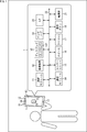
- FIG. 2 is a block diagram showing a detailed configuration example of the ranging module 11. Note that FIG. 2 also shows other blocks of the smartphone 1 related to the detection process of the ranging module 11.
- the distance measurement module 11 is a distance measurement module that performs distance measurement by the Indirect ToF method, and has a light emitting unit 41, a light emission control unit 42, and a distance measurement sensor 43.
- the distance measuring module 11 irradiates an object with light, and the light (irradiation light) is reflected by the object and receives the returned light (reflected light) to receive a depth map as distance information to the object. (Distance image) and reliability map (reliability image) as luminance information are generated and output.
- the distance measuring sensor 43 has a light receiving unit 51 and a signal processing unit 52.
- the distance measuring sensor 43 can be manufactured as a one-chip semiconductor package (CSP) composed of a laminated substrate in which a first semiconductor substrate and a second semiconductor substrate are laminated, and has an incident surface on which reflected light is input.
- a pixel array unit is arranged on one semiconductor substrate, and a logic circuit, a memory circuit, and the like serving as a signal processing unit 52 are arranged on the second semiconductor substrate.
- the distance measuring sensor 43 may be divided into two or more chips, or may be configured by a one-chip semiconductor package (CSP) composed of a laminated substrate of three or more semiconductor substrates. Good.
- the light emitting unit 41 has, for example, an infrared laser diode or the like as a light source, and emits light while being modulated at a timing corresponding to the light emission control signal supplied from the light emission control unit 42 according to the control by the light emission control unit 42, and emits light to an object. And irradiate the irradiation light.
- the light emission control unit 42 controls the light emission of the light emission unit 41 by supplying the light emission control signal for controlling the frequency (for example, 20 MHz or the like) when the light source is made to emit light and the light emission amount. Further, in order to drive the light receiving unit 51 in accordance with the timing of light emission in the light emitting unit 41, the light emitting control unit 42 also supplies a light emitting control signal to the light receiving unit 51.
- the light receiving unit 51 receives the reflected light that is reflected by the object and returned.
- the light receiving unit 51 has a pixel array unit in which the pixels that generate an electric charge according to the amount of received light and output a signal corresponding to the electric charge are two-dimensionally arranged in a matrix in the row direction and the column direction.
- the light-receiving signal A and the light-receiving signal B obtained by distributing the electric charge according to the amount of received light for each pixel to the first tap and the second tap are output to the signal processing unit 52.
- the details of the light receiving operation of the light receiving unit 51 will be described later with reference to FIGS. 3 to 7.
- the signal processing unit 52 includes a control unit 61, a depth calculation unit 62, and a detection processing unit 63.
- the sensor hub 19 issues a start command for starting the distance measurement to the control unit of the distance measurement sensor 43.
- the operation that triggers the start of the detection process includes, for example, the operation of moving the smartphone 1 supplied from the inertial sensor (gyro sensor, acceleration sensor) which is one of the sensor units 15, or one of the operation buttons 18. Examples include an operation in which the power button is pressed, an operation in which a predetermined application program is started, which is detected by the touch sensor 13T, and the like.
- the control unit 61 instructs the light emission control unit 42 to start light emission.
- the control unit 61 can specify a predetermined frequency and a light emitting amount so that the exposure amount is appropriately adjusted (exposure control) based on the light receiving signal supplied from the light receiving unit 51.
- a predetermined frequency and light emission amount are set as initial values.
- control unit 61 selects a predetermined operation mode from a plurality of operation modes registered in advance, and causes the detection processing unit 63 to execute a predetermined detection process corresponding to the selected operation mode.
- the operation mode is, for example, specified by a command or the like from the sensor hub 19, or is specified by a high or low voltage signal of an input / output terminal connected to the sensor hub 19. Therefore, the control unit 61 detects the operation mode designated from the sensor hub 19 and selects the detected operation mode.
- the depth calculation unit 62 generates a depth map and a reliability map from the two light receiving signals A and B of each pixel supplied from the light receiving unit 51. More specifically, the depth calculation unit 62 calculates the depth value, which is the distance from the distance measuring module 11 to the object, for each pixel of the light receiving unit 51. Then, the depth calculation unit 62 generates a depth map in which the depth value is stored as the pixel value of each pixel. Further, the depth calculation unit 62 also calculates the reliability of the calculated depth value for each pixel of the light receiving unit 51, and generates a reliability map in which the reliability is stored as the pixel value of each pixel.
- the detection processing unit 63 executes a predetermined detection processing by using at least one of the depth map as the distance information and the reliability map as the brightness information in accordance with the operation mode specified by the control unit 61. Then, the detection processing unit 63 outputs the result of the detection processing to the sensor hub 19 together with the depth map and the reliability map.
- the detection processing unit 63 changes the type (processing content), order (sequence), number, etc. of the detection processing according to the control of the control unit 61 according to the operation mode.
- the control unit 61 causes the detection processing unit 63 to execute predetermined detection processing having different types (processing contents), order (sequence), number, and the like according to the operation mode. The details of the detection process will be described later.
- the detection processing result and the depth map and reliability map output to the sensor hub 19 are supplied to the AP20.
- the AP20 executes the face recognition process based on the depth map and the reliability map.
- FIG. 3 shows a detailed configuration example of the light receiving unit 51.
- the light receiving unit 51 generates a charge corresponding to the amount of received light, and a pixel array unit 72 and a pixel array in which pixels 71 that output a signal corresponding to the charge are two-dimensionally arranged in a matrix in the row direction and the column direction. It has a drive control circuit 73 arranged in a peripheral region of the unit 72.
- the drive control circuit 73 has, for example, a control signal for controlling the drive of the pixel 71 based on a light emission control signal supplied from the light emission control unit 42 (for example, a distribution signal DIMIX or a selection signal ADDRESS DECODE, which will be described later). Reset signal RST, etc.) is output.
- the pixel 71 has a photodiode 81 and a first tap 82A and a second tap 82B that detect the charge photoelectrically converted by the photodiode 81.
- the electric charge generated by one photodiode 81 is distributed to the first tap 82A or the second tap 82B.
- the charges distributed to the first tap 82A are output as a light receiving signal A from the signal line 83A, and the charges distributed to the second tap 82B are received from the signal line 83B. Is output as.
- the first tap 82A is composed of a transfer transistor 91A, an FD (Floating Diffusion) unit 92A, a selection transistor 93A, and a reset transistor 94A.
- the second tap 82B is composed of a transfer transistor 91B, an FD unit 92B, a selection transistor 93B, and a reset transistor 94B.
- the reflected light is received by the photodiode 81 with a delay of ⁇ T.
- the distribution signal DIMIX_A controls the on / off of the transfer transistor 91A
- the distribution signal DIMIX_B controls the on / off of the transfer transistor 91B.
- the distribution signal DIMIX_A is a signal having the same phase as the irradiation light
- the distribution signal DIMIX_B has a phase in which the distribution signal DIMIX_A is inverted.
- the electric charge generated by the photodiode 81 receiving the reflected light is transferred to the FD unit 92A according to the distribution signal DIMIX_A while the transfer transistor 91A is on, and is transferred to the transfer transistor according to the distribution signal DIMIX_B. While 91B is on, it is transferred to the FD unit 92B.
- the charges transferred via the transfer transistor 91A are sequentially accumulated in the FD section 92A and transferred via the transfer transistor 91B during a predetermined period in which the irradiation light of the irradiation time T is periodically irradiated.
- the electric charge is sequentially accumulated in the FD unit 92B.
- the selection transistor 93A is turned on according to the selection signal ADDRESS DECODE_A after the end of the period for accumulating the electric charge
- the electric charge accumulated in the FD unit 92A is read out via the signal line 83A and corresponds to the amount of the electric charge.
- the light receiving signal A is output from the light receiving unit 51.
- the selection transistor 93B is turned on according to the selection signal ADDRESS DECODE_B
- the electric charge accumulated in the FD unit 92B is read out via the signal line 83B, and the light receiving signal B corresponding to the amount of the electric charge is transmitted from the light receiving unit 51. It is output.
- the charge stored in the FD section 92A is discharged when the reset transistor 94A is turned on according to the reset signal RST_A, and the charge stored in the FD section 92B is discharged when the reset transistor 94B is turned on according to the reset signal RST_B. Will be done.
- the pixel 71 distributes the electric charge generated by the reflected light received by the photodiode 81 to the first tap 82A or the second tap 82B according to the delay time ⁇ T, and outputs the light receiving signal A and the light receiving signal B.
- the delay time ⁇ T corresponds to the time when the light emitted by the light emitting unit 41 flies to the object, is reflected by the object, and then flies to the light receiving unit 51, that is, the distance to the object. Therefore, the distance measuring module 11 can obtain the distance (depth value) to the object according to the delay time ⁇ T based on the light receiving signal A and the light receiving signal B.
- the light receiving signal A and the light receiving light have different effects for each pixel 71 due to the deviation (sensitivity difference) of the characteristics of each element of the pixel transistor such as the photodiode 81 and the transfer transistor 91 of each pixel 71. It may be given to signal B. Therefore, in the Indirect ToF type ranging module 11, the sensitivity difference between the taps of each pixel is eliminated by acquiring the light receiving signal A and the light receiving signal B that receive the reflected light by changing the phase with the same pixel 71. , A method to improve the SN ratio is adopted.
- the light receiving unit 51 receives the reflected light at the light receiving timings whose phases are shifted by 0 °, 90 °, 180 °, and 270 ° with respect to the irradiation timing of the irradiation light. More specifically, the light receiving unit 51 receives light with the phase set to 0 ° with respect to the irradiation timing of the irradiation light in a certain frame period, and receives light with the phase set to 90 ° in the next frame period. In the frame period, the light is received with the phase set to 180 °, and in the next frame period, the light is received with the phase set to 270 °, and so on.
- FIG. 6 is a diagram showing the exposure periods of the first tap 82A of the pixel 71 in each phase of 0 °, 90 °, 180 °, and 270 ° side by side so that the phase difference can be easily understood.
- the light receiving signal A obtained by receiving light in the same phase (phase 0 °) as the irradiation light is shifted by 90 degrees from the light receiving signal A 0 and the irradiation light (phase).
- the light-receiving signal A obtained by receiving light at 90 °) is received by the light-receiving signal A 90
- the light-receiving signal A obtained by receiving light in a phase (phase 180 °) shifted by 180 degrees from the irradiation light is received by the light-receiving signal A 180 , the irradiation light and 270.
- the light receiving signal A obtained by receiving light in a phase shifted (phase 270 °) is referred to as a light receiving signal A 270 .
- the light receiving signal B obtained by receiving light at the second tap 82B in the same phase (phase 0 °) as the irradiation light is shifted by 90 degrees from the light receiving signal B 0 and the irradiation light (phase).
- the light-receiving signal B obtained by receiving light at 90 °) is received by the light-receiving signal B 90
- the light-receiving signal B obtained by receiving light in a phase (phase 180 °) shifted by 180 degrees from the irradiation light is received by the light-receiving signal B 180 and the irradiation light and 270.
- the light receiving signal B obtained by receiving light in a shifted phase (phase 270 °) is referred to as a light receiving signal B 270 .
- FIG. 7 is a diagram for explaining the calculation method of the depth value and the reliability by the 2Phase method and the 4Phase method.
- the depth value d can be obtained by the following equation (1).
- equation (1) c is the speed of light
- ⁇ T is the delay time
- f is the modulation frequency of light.
- ⁇ in the equation (1) represents the phase shift amount [rad] of the reflected light, and is represented by the following equation (2).
- I and Q of the equation (2) set the phases to 0 °, 90 °, 180 ° and 270 ° to obtain the received light signals A 0 to A 270 and the received light signals B 0 to B 270 . It is calculated by the following equation (3).
- I and Q are signals obtained by converting the phase of the cos wave from polar coordinates to a Cartesian coordinate system (IQ plane), assuming that the change in brightness of the irradiation light is a cos wave.
- the 2Phase method two of the light receiving signals A 0 to A 270 and the light receiving signals B 0 to B 270 obtained by setting the phases to 0 °, 90 °, 180 ° and 270 ° are orthogonal to each other.
- the depth value d to the object can be obtained using only the phase.
- the I and Q of the equation (2) become the following equation (4).
- the I and Q of the equation (2) become the following equation (5).
- the characteristic variation between taps existing in each pixel cannot be removed, but the depth value d to the object can be obtained only from the received signals of two phases, so the frame is twice that of the 4Phase method.
- Distance measurement can be performed at a rate.
- the characteristic variation between taps can be adjusted by correction parameters such as gain and offset.
- the reliability cnf can be obtained by the following equation (6).
- the ranging module 11 is either an I signal or a Q signal corresponding to the delay time ⁇ T calculated by the 4 Phase method or an I signal or the Q signal corresponding to the delay time ⁇ T calculated by the 2 Phase method. It does not matter whether the depth value d and the reliability cnf are used with. Either the 4Phase method or the 2Phase method may be used in a fixed manner, or may be, for example, a method of appropriately selecting or blending according to the movement of an object or the like. In the following, for the sake of simplicity, the 4Phase method will be adopted.
- the detection processing unit 63 performs a predetermined detection process using at least one of the depth map and the reliability map supplied from the depth calculation unit 62 according to the current operation mode selected from the plurality of operation modes. It is executed and the result of the detection process is output to the sensor hub 19 together with the depth map and the reliability map.
- FIG. 8 shows a specific detection process executed in a predetermined operation mode among a plurality of operation modes.
- the four operation modes A to D shown in FIG. 8 are examples of the operation modes included in the signal processing unit 52, and also have other operation modes.
- the detection processing unit 63 can execute, for example, proximity detection processing, head detection processing, face detection processing, and pupil detection processing as detection processing using at least one of the depth map and the reliability map. ..
- the proximity detection process is a process for detecting whether or not there is an object (proximity object) within a predetermined distance from the smartphone 1.
- the original target of the proximity detection process is the user's face (head), but in the proximity process, not only the human face but also a predetermined object at the proximity position of the smartphone 1. If there is a (proximity object), it is determined that there is a proximity object.
- the head detection process is a process for detecting the head of a user (human).
- the face detection process is a process for detecting a user's face.
- the pupil detection process is a process of detecting the user's eyes and line of sight.
- the proximity detection process, the head detection process, the face detection process, and the pupil detection process are executed in that order, and the detection target is detected in the first detection process executed first. In this case, the process of executing the next second detection process is sequentially repeated. Then, when the pupil to be detected is detected in the final pupil detection process, the pupil detection result is output to the sensor hub 19 together with the depth map and the reliability map.
- the proximity detection process, the head detection process, the face detection process, and the pupil detection process are executed in that order, and the first detection executed first.
- the process of executing the next second detection process is sequentially repeated.
- the difference between the detection process of the operation mode B and the detection process of the operation mode A is that when the detection target is detected by each detection process, the detection result is output to the sensor hub 19. Then, when the pupil to be detected is detected in the final pupil detection process, the pupil detection result, the depth map, and the reliability map are output to the sensor hub 19.
- the detection process of the operation mode C is a process of executing only the proximity detection process and the head detection process among the four detection processes executed in the operation mode B.
- the detection result is output to the sensor hub 19, and when the head is detected in the next head detection processing, the detection result and the depth map And the reliability map is output to the sensor hub 19.
- the detection processing of the operation mode C includes two of the four detection processes of proximity detection processing, head detection processing, face detection processing, and pupil detection processing, proximity detection processing and head detection processing.
- the detection processing unit 63 also has another operation mode for executing the detection process in which one or more of the four detection processes are combined in an arbitrary order. For example, the detection processing unit 63 executes only proximity processing, and outputs the detection result, the depth map, and the reliability map to the sensor hub 19, and performs proximity processing and face detection processing in that order.
- the detection result is output to the sensor hub 19, and then the face detection process is executed.
- the detection result and the depth map and It also has an operation mode for outputting the reliability map to the sensor hub 19.
- the detection process of the operation mode D is a process of executing the proximity detection process, the head detection process, the face detection process, and the pupil detection process in that order, as in the operation mode A.
- the difference between the detection process of the operation mode D and the detection process of the operation mode A is that the detection result of the first detection process executed earlier is output to the sensor hub 19 and is based on the detection result of the first detection process. Then, when the sensor hub 19 instructs the next second detection process, the second detection process is executed. Then, when the pupil is detected in the final pupil detection process, the pupil detection result, the depth map, and the reliability map are output to the sensor hub 19.
- the operation mode detection process includes at least one of proximity detection process, head detection process, face detection process, and pupil detection process, and in any operation mode detection process, a series of detections according to the operation mode When the final detection process of the process is successful (the detection target is detected), the detection result and the depth map and the reliability map are output to the sensor hub 19.
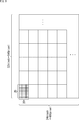
- FIG. 9 is a diagram illustrating a specific processing example of the proximity detection processing.
- the pixel array unit 72 of the light receiving unit 51 has a pixel array consisting of 640 pixels in the horizontal direction and 480 pixels in the vertical direction. Further, in the depth map and the reliability map used when executing the detection process, the exposure amount is appropriately adjusted (exposure control) in the light receiving unit 51 based on the light emission control signal that controls the frequency and the light emission amount. It is assumed that it is generated based on the received signal.
- the detection processing unit 63 divides all the pixels of 640x480 into one block for each 20 pixels in the horizontal direction and the vertical direction, and divides it into 32x24 blocks. Then, the detection processing unit 63 determines a predetermined one block as the detection target block from all the blocks of 32x24.
- the detection target block is, for example, a block located at the center of the pixel array unit 72.
- the detection processing unit 63 calculates the average value d_ave of the depth value d of the 20 ⁇ 20 pixels constituting the detection target block and the average value cnf_ave of the reliability cnf.
- the detection processing unit 63 has a predetermined range in which the average value d_ave of the depth values is determined to be a close distance and the average value cnf_ave of the reliability cnf is in a predetermined range determined to be normal detection. In addition, it detects that the user is in the proximity position of the smartphone 1.
- the distance is close when the average depth value d_ave is within 70 cm. ..
- FIG. 10 is a diagram illustrating a specific processing example of the head detection processing.
- the detection processing unit 63 calculates the average value cnf_ave of the reliability cnf of all 32x24 blocks, and detects the user's head based on the calculated average value cnf_ave of the reliability cnf of all blocks. To do. Since the reliability cnf corresponds to the luminance information (luminance value), for example, the average value cnf_ave of the reliability cnf of a 32x24 block is regarded as a low-resolution two-dimensional image, and the user's head is treated in the manner of pattern matching. Can be detected.
- FIG. 11 is a diagram illustrating a specific processing example of the face detection processing.
- the detection processing unit 63 divides all the pixels of 640x480 into one block by dividing it into two pixels in each of the horizontal direction and the vertical direction, and divides it into 320x240 blocks. Then, the detection processing unit 63 calculates the average value cnf_ave of the reliability cnf of all the blocks of 320x240, and detects the user's face based on the calculated average value cnf_ave of the reliability cnf of all the blocks.
- the average value cnf_ave of the reliability cnf of all blocks of 320x240 is regarded as a low-resolution two-dimensional image, and the user's face, eyes, and the user's face are treated in the manner of pattern matching. , When the mouth is detected, it can be determined that the user's face has been detected.
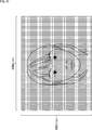
- FIG. 12 is a diagram illustrating a specific processing example of the pupil detection processing.
- the detection processing unit 63 detects the user's pupil by using the average value cnf_ave of the reliability cnf of all pixels of 640x480 as it is. Similar to the face detection process, the user's eyes detect the vicinity of the position of the eyes of the face in the manner of pattern matching, and detect that the user's eyes are open and facing a predetermined direction. If so, it can be determined that the user's eyes have been detected.
- the detection processing unit 63 has 2
- the detection process can be executed by setting the resolution so that the resolution of the depth map or reliability map regarded as a dimensional image increases as the detection process is performed later. As a result, both the accuracy of the detection process (high accuracy) and the processing time (high-speed processing time) can be realized.
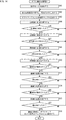
- the distance measuring sensor 43 is provided.
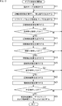
- step S11 the control unit 61 of the signal processing unit 52 instructs the light emission control unit 42 to start light emission, and sets the operation mode designated by the sensor hub 19.
- the light emission control unit 42 supplies the light emission control signal for controlling the frequency and the light emission amount when the light source is made to emit light.
- the light emitting unit 41 emits light while being modulated at a timing corresponding to the light emission control signal supplied from the light emission control unit 42, and irradiates the object with irradiation light.
- step S12 the light receiving unit 51 executes a photoelectric conversion process of receiving the light (reflected light) reflected by the object and performing photoelectric conversion, and the first tap 82A and the second tap in each pixel 71 of the pixel array unit 72.
- the light receiving signal A and the light receiving signal B obtained by distributing the electric charge to the 82B are output to the depth calculation unit 62 of the signal processing unit 52.
- step S13 the depth calculation unit 62 generates a depth map and a reliability map from the two light receiving signals A and B of each pixel 71 supplied from the pixel array unit 72 of the light receiving unit 51.
- the generated depth map and reliability map are supplied to the detection processing unit 63.
- step S14 the detection processing unit 63 executes proximity detection processing for detecting whether or not there is a user in the proximity position of the smartphone 1.
- step S15 the detection processing unit 63 determines whether or not a nearby object has been detected based on the execution result of the proximity detection process. If it is determined in step S15 that a nearby object has not been detected, the process returns to step S12.
- step S15 if it is determined in step S15 that a nearby object has been detected, the process proceeds to step S16, the detection processing unit 63 outputs the proximity detection result to the sensor hub 19, and proceeds to the process in step S17.
- step S17 the detection processing unit 63 executes a head detection process for detecting the user's head.
- step S18 the detection processing unit 63 determines whether or not the head has been detected based on the execution result of the head detection processing. If it is determined in step S18 that the head is not detected, the process returns to step S12.
- step S18 determines whether the head has been detected. If it is determined in step S18 that the head has been detected, the process proceeds to step S19, the detection processing unit 63 outputs the head detection result to the sensor hub 19, and proceeds to the process in step S20. ..
- step S20 the detection processing unit 63 executes a face detection process for detecting the user's face.
- step S21 the detection processing unit 63 determines whether or not the face has been detected based on the execution result of the face detection processing. If it is determined in step S21 that the face has not been detected, the process returns to step S12.
- step S21 if it is determined in step S21 that the face has been detected, the process proceeds to step S22, the detection processing unit 63 outputs the face detection result to the sensor hub 19, and proceeds to the process in step S23.
- step S23 the detection processing unit 63 executes pupil detection processing for detecting the user's eyes and line of sight.
- step S24 the detection processing unit 63 determines whether or not the pupil has been detected based on the execution result of the pupil detection process. If it is determined in step S24 that the pupil has not been detected, the process returns to step S12.
- step S24 determines whether the pupil has been detected. If it is determined in step S24 that the pupil has been detected, the process proceeds to step S25, and the detection processing unit 63 outputs the pupil detection result together with the depth map and the reliability map to the sensor hub 19 for processing. To finish.
- the depth measurement process when the operation mode B is set as the operation mode is executed as described above.
- the depth measurement process when the operation mode A is set as the operation mode is a process of outputting the detection result in each detection process other than the final pupil detection process in the depth measurement process of FIG. 13, specifically, Step S16, step S19, and step S22 correspond to the omitted processing.
- the depth measurement process in the operation mode D is equivalent to the process in which the processes of steps S47, S51, and S55 are added to the depth measurement process in the operation mode B described with reference to FIG.
- step S47 is added between step S46 of FIG. 14 corresponding to step S16 of FIG. 13 and step S48 of FIG. 14 corresponding to step S17 of FIG. 13, and step S51 is shown in FIG. It is added between step S50 of FIG. 14 corresponding to step S19 of 13 and step S52 of FIG. 14 corresponding to step S20 of FIG. 13, and step S55 corresponds to step S22 of FIG. It is added between S54 and step S56 of FIG. 14, which corresponds to step S23 of FIG.
- step S47 after the proximity detection result is output to the sensor hub 19 in step S46, the detection processing unit 63 determines whether the head detection is instructed by the sensor hub 19. If it is determined in step S47 that the head detection is not instructed, the process returns to step S42. On the other hand, if it is determined in step S47 that the head detection is instructed, the process proceeds to step S48, and the head detection process is executed.
- step S51 after the head detection result is output to the sensor hub 19 in step S50, the detection processing unit 63 determines whether face detection is instructed by the sensor hub 19. If it is determined in step S51 that face detection is not instructed, the process returns to step S42. On the other hand, if it is determined in step S51 that the face detection is instructed, the process proceeds to step S52, and the face detection process is executed.
- step S55 after the proximity detection result is output to the sensor hub 19 in step S54, the detection processing unit 63 determines whether or not pupil detection is instructed by the sensor hub 19. If it is determined in step S55 that pupil detection is not instructed, the process returns to step S42. On the other hand, if it is determined in step S55 that the pupil detection is instructed, the process proceeds to step S56, and the pupil detection process is executed.
- the point of execution based on the instruction of the next detection process from the sensor hub 19 is the depth measurement process when the operation mode B is set. Different from.
- the depth measurement process is continued indefinitely when the pupil detection is not successful in the end.
- individual detection processes are performed.
- error processing such as ending the depth measurement process if it is not successful for a certain period of time is incorporated.
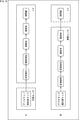
- a general distance measuring sensor generates only a depth map and a reliability map and outputs them as distance measuring data.
- the AP20 executes the proximity detection process, the head detection process, the face detection process, and the pupil detection process based on the depth map and the reliability map, and the face is detected on condition that the pupil detection process is successful. Execute the authentication process. Until the pupil detection process succeeds, it is necessary to repeatedly execute while acquiring a large number of depth maps and reliability maps, and since the AP20 is a device that consumes a large amount of power, the power consumption of the smartphone 1 also increases. ..
- the distance measuring sensor 43 to which the present technology is applied as shown in B of FIG. 15, not only the depth map and the reliability map are generated, but also the proximity detection process, the head detection process, and the face are detected.
- the detection process and the pupil detection process can also be executed, and only when the pupil detection process is successful and the face can be accurately identified, the pupil detection result, the depth map, and the reliability map are AP20. Is output to. As a result, AP20 is activated and the face recognition process is executed.
- the distance measuring module 11 described above is also mounted on electronic devices such as tablet terminals, mobile phones, personal computers, game machines, television receivers, wearable terminals, digital still cameras, and digital video cameras. can do.
- the technology according to the present disclosure can be applied to various products.
- the technology according to the present disclosure is realized as a device mounted on a moving body of any kind such as an automobile, an electric vehicle, a hybrid electric vehicle, a motorcycle, a bicycle, a personal mobility, an airplane, a drone, a ship, and a robot. You may.
- FIG. 16 is a block diagram showing a schematic configuration example of a vehicle control system, which is an example of a mobile control system to which the technique according to the present disclosure can be applied.
- the vehicle control system 12000 includes a plurality of electronic control units connected via the communication network 12001.
- the vehicle control system 12000 includes a drive system control unit 12010, a body system control unit 12020, an outside information detection unit 12030, an in-vehicle information detection unit 12040, and an integrated control unit 12050.
- a microcomputer 12051, an audio image output unit 12052, and an in-vehicle network I / F (interface) 12053 are shown as a functional configuration of the integrated control unit 12050.
- the drive system control unit 12010 controls the operation of the device related to the drive system of the vehicle according to various programs.
- the drive system control unit 12010 provides a driving force generator for generating the driving force of the vehicle such as an internal combustion engine or a driving motor, a driving force transmission mechanism for transmitting the driving force to the wheels, and a steering angle of the vehicle. It functions as a control device such as a steering mechanism for adjusting and a braking device for generating a braking force of a vehicle.
- the body system control unit 12020 controls the operation of various devices mounted on the vehicle body according to various programs.
- the body system control unit 12020 functions as a keyless entry system, a smart key system, a power window device, or a control device for various lamps such as headlamps, back lamps, brake lamps, blinkers or fog lamps.
- the body system control unit 12020 may be input with radio waves transmitted from a portable device that substitutes for the key or signals of various switches.
- the body system control unit 12020 receives inputs of these radio waves or signals and controls a vehicle door lock device, a power window device, a lamp, and the like.
- the vehicle outside information detection unit 12030 detects information outside the vehicle equipped with the vehicle control system 12000.
- the image pickup unit 12031 is connected to the vehicle exterior information detection unit 12030.
- the vehicle outside information detection unit 12030 causes the image pickup unit 12031 to capture an image of the outside of the vehicle and receives the captured image.
- the vehicle exterior information detection unit 12030 may perform object detection processing or distance detection processing such as a person, a vehicle, an obstacle, a sign, or characters on the road surface based on the received image.
- the image pickup unit 12031 is an optical sensor that receives light and outputs an electric signal according to the amount of the light received.
- the imaging unit 12031 can output an electric signal as an image or can output it as distance measurement information. Further, the light received by the imaging unit 12031 may be visible light or invisible light such as infrared light.
- the in-vehicle information detection unit 12040 detects the in-vehicle information.
- a driver state detection unit 12041 that detects the driver's state is connected to the in-vehicle information detection unit 12040.
- the driver state detection unit 12041 includes, for example, a camera that images the driver, and the in-vehicle information detection unit 12040 determines the degree of fatigue or concentration of the driver based on the detection information input from the driver state detection unit 12041. It may be calculated, or it may be determined whether the driver is dozing.
- the microcomputer 12051 calculates the control target value of the driving force generator, the steering mechanism, or the braking device based on the information inside and outside the vehicle acquired by the vehicle exterior information detection unit 12030 or the vehicle interior information detection unit 12040, and the drive system control unit.
- a control command can be output to 12010.
- the microcomputer 12051 realizes ADAS (Advanced Driver Assistance System) functions including vehicle collision avoidance or impact mitigation, follow-up running based on inter-vehicle distance, vehicle speed maintenance running, vehicle collision warning, or vehicle lane deviation warning. It is possible to perform cooperative control for the purpose of.
- ADAS Advanced Driver Assistance System
- the microcomputer 12051 controls the driving force generator, the steering mechanism, the braking device, and the like based on the information around the vehicle acquired by the vehicle exterior information detection unit 12030 or the vehicle interior information detection unit 12040. It is possible to perform coordinated control for the purpose of automatic driving that runs autonomously without depending on the operation.
- the microcomputer 12051 can output a control command to the body system control unit 12020 based on the information outside the vehicle acquired by the vehicle exterior information detection unit 12030.
- the microcomputer 12051 controls the headlamps according to the position of the preceding vehicle or the oncoming vehicle detected by the external information detection unit 12030, and performs coordinated control for the purpose of antiglare such as switching the high beam to the low beam. It can be carried out.
- the audio image output unit 12052 transmits the output signal of at least one of the audio and the image to the output device capable of visually or audibly notifying the passenger or the outside of the vehicle of the information.
- an audio speaker 12061, a display unit 12062, and an instrument panel 12063 are exemplified as output devices.
- the display unit 12062 may include, for example, at least one of an onboard display and a heads-up display.
- FIG. 17 is a diagram showing an example of the installation position of the imaging unit 12031.
- the vehicle 12100 has image pickup units 12101, 12102, 12103, 12104, 12105 as the image pickup unit 12031.
- the imaging units 12101, 12102, 12103, 12104, 12105 are provided at positions such as the front nose, side mirrors, rear bumpers, back doors, and the upper part of the windshield in the vehicle interior of the vehicle 12100, for example.
- the imaging unit 12101 provided on the front nose and the imaging unit 12105 provided on the upper part of the windshield in the vehicle interior mainly acquire an image in front of the vehicle 12100.
- the imaging units 12102 and 12103 provided in the side mirrors mainly acquire images of the side of the vehicle 12100.
- the imaging unit 12104 provided on the rear bumper or the back door mainly acquires an image of the rear of the vehicle 12100.
- the images in front acquired by the imaging units 12101 and 12105 are mainly used for detecting a preceding vehicle or a pedestrian, an obstacle, a traffic light, a traffic sign, a lane, or the like.
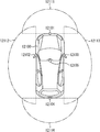
- FIG. 17 shows an example of the photographing range of the imaging units 12101 to 12104.
- the imaging range 12111 indicates the imaging range of the imaging unit 12101 provided on the front nose
- the imaging ranges 12112 and 12113 indicate the imaging ranges of the imaging units 12102 and 12103 provided on the side mirrors, respectively
- the imaging range 12114 indicates the imaging range of the imaging units 12102 and 12103.
- the imaging range of the imaging unit 12104 provided on the rear bumper or the back door is shown. For example, by superimposing the image data captured by the imaging units 12101 to 12104, a bird's-eye view image of the vehicle 12100 as viewed from above can be obtained.
- At least one of the imaging units 12101 to 12104 may have a function of acquiring distance information.
- at least one of the image pickup units 12101 to 12104 may be a stereo camera composed of a plurality of image pickup elements, or may be an image pickup element having pixels for phase difference detection.
- the microcomputer 12051 has a distance to each three-dimensional object within the imaging range 12111 to 12114 based on the distance information obtained from the imaging units 12101 to 12104, and a temporal change of this distance (relative velocity with respect to the vehicle 12100).
- a predetermined speed for example, 0 km / h or more.
- the microcomputer 12051 can set an inter-vehicle distance to be secured in front of the preceding vehicle in advance, and can perform automatic braking control (including follow-up stop control), automatic acceleration control (including follow-up start control), and the like. In this way, it is possible to perform cooperative control for the purpose of automatic driving or the like in which the vehicle travels autonomously without depending on the operation of the driver.
- the microcomputer 12051 converts three-dimensional object data related to a three-dimensional object into two-wheeled vehicles, ordinary vehicles, large vehicles, pedestrians, utility poles, and other three-dimensional objects based on the distance information obtained from the imaging units 12101 to 12104. It can be classified and extracted and used for automatic avoidance of obstacles. For example, the microcomputer 12051 distinguishes obstacles around the vehicle 12100 into obstacles that can be seen by the driver of the vehicle 12100 and obstacles that are difficult to see. Then, the microcomputer 12051 determines the collision risk indicating the risk of collision with each obstacle, and when the collision risk is equal to or higher than the set value and there is a possibility of collision, the microcomputer 12051 via the audio speaker 12061 or the display unit 12062. By outputting an alarm to the driver and performing forced deceleration and avoidance steering via the drive system control unit 12010, driving support for collision avoidance can be provided.
- At least one of the imaging units 12101 to 12104 may be an infrared camera that detects infrared rays.
- the microcomputer 12051 can recognize a pedestrian by determining whether or not a pedestrian is present in the captured image of the imaging units 12101 to 12104.
- pedestrian recognition includes, for example, a procedure for extracting feature points in an image captured by an imaging unit 12101 to 12104 as an infrared camera, and pattern matching processing for a series of feature points indicating the outline of an object to determine whether or not the pedestrian is a pedestrian. It is done by the procedure to determine.
- the audio image output unit 12052 When the microcomputer 12051 determines that a pedestrian is present in the captured images of the imaging units 12101 to 12104 and recognizes the pedestrian, the audio image output unit 12052 outputs a square contour line for emphasizing the recognized pedestrian.
- the display unit 12062 is controlled so as to superimpose and display. Further, the audio image output unit 12052 may control the display unit 12062 so as to display an icon or the like indicating a pedestrian at a desired position.
- the above is an example of a vehicle control system to which the technology according to the present disclosure can be applied.
- the technique according to the present disclosure can be applied to the in-vehicle information detection unit 12040 or the driver state detection unit 12041 among the configurations described above. Specifically, by using the depth measurement process by the distance measuring module 11 as the in-vehicle information detection unit 12040 or the driver state detection unit 12041, various detection processes before the driver's face recognition process is performed. , The subsequent face recognition process can be performed accurately, and the driver's condition can be detected more accurately.
- this technology can be applied to a method called the Continuous-Wave method, which is an Indirect ToF method that amplitude-modulates the light projected onto an object.
- the structure of the photodiode 81 of the light receiving unit 51 can be applied to a distance measuring sensor having a CAPD (Current Assisted Photonic Demodulator) structure. Further, this technique may be applied to a Structured Light type ranging sensor.
- CAPD Current Assisted Photonic Demodulator
- the configuration described as one device (or processing unit) may be divided and configured as a plurality of devices (or processing units).
- the configurations described above as a plurality of devices (or processing units) may be collectively configured as one device (or processing unit).
- a configuration other than the above may be added to the configuration of each device (or each processing unit).
- a part of the configuration of one device (or processing unit) may be included in the configuration of another device (or other processing unit). ..
- the system means a set of a plurality of components (devices, modules (parts), etc.), and it does not matter whether all the components are in the same housing. Therefore, a plurality of devices housed in separate housings and connected via a network, and a device in which a plurality of modules are housed in one housing are both systems. ..
- the above-mentioned program can be executed in any device.
- the device may have necessary functions (functional blocks, etc.) so that necessary information can be obtained.
- the present technology can have the following configurations.
- a light receiving unit that receives the reflected light that is reflected by an object and returned from the light emitted from a predetermined light emitting source.
- a depth calculation unit that calculates distance information and luminance information to the object from the signal obtained by the light receiving unit, and
- a predetermined detection process is executed using at least one of the distance information and the brightness information in accordance with the current operation mode selected from the plurality of operation modes, and the result of the detection process is the distance information and the brightness.
- a distance measuring sensor equipped with a detection processing unit that outputs information together with the outside.
- One of the operation modes is a mode for executing a plurality of detection processes including a first detection process and a second detection process.
- the detection processing unit executes the second detection process when the detection target is detected in the first detection process, and when the detection target is detected in the second detection process, the first detection processing unit executes the second detection process.
- the distance measuring sensor according to (1) wherein the result of the detection process of 2 is output to the outside together with the distance information and the luminance information.
- the detection processing unit outputs the result of the first detection process to the outside and executes the second detection process (2).
- One of the operation modes is a mode for executing a plurality of detection processes including a first detection process and a second detection process.
- the detection processing unit When the detection target is detected in the first detection process, the detection processing unit outputs the result of the first detection process to the outside, and supplies an execution instruction of the second detection process from the outside. When this is done, the second detection process is executed, and when the detection target is detected in the second detection process, the result of the second detection process is output to the outside together with the distance information and the brightness information.
- the distance measuring sensor according to any one of (1) to (3) above.
- One of the operation modes is a mode in which a plurality of detection processes are executed in order.
- the distance measuring sensor according to any one of (1) to (4), wherein the resolution of the distance information or the luminance information of the detection process increases as the detection process is performed later.
- the distance measuring sensor according to any one of (1) to (5) above, wherein the detection process includes at least one of proximity detection process, head detection process, face detection process, and pupil detection process.
- One of the operation modes is a mode in which the detection process executes any one of the proximity detection process, the head detection process, the face detection process, and the pupil detection process (6).
- Distance measurement sensor described in Crab Any of the above (1) to (7), further comprising a control unit that selects a predetermined operation mode from a plurality of operation modes and causes the detection processing unit to execute a predetermined detection process corresponding to the current operation mode.
- the distance information and the brightness information to the object are calculated from the signal obtained by receiving the reflected light returned by the light emitted from the predetermined light emitting source reflected by the object.
- a predetermined detection process is executed using at least one of the distance information and the brightness information according to the current operation mode selected from the plurality of operation modes, and the result of the detection process is the distance information and the brightness.
- a signal processing method that outputs information to the outside.
- a light emitting part having a predetermined light emitting source and Equipped with a distance measuring sensor The distance measuring sensor is A light receiving unit that receives the reflected light that is reflected by an object and returned from the light emitted from the predetermined light emitting source.
- a depth calculation unit that calculates distance information and luminance information to the object from the signal obtained by the light receiving unit, and A predetermined detection process is executed using at least one of the distance information and the brightness information according to the current operation mode selected from the plurality of operation modes, and the result of the detection process is the distance information and the brightness.
- a distance measuring module equipped with a detection processing unit that outputs information together with the outside.
- 1 smartphone 11 distance measurement module, 15 sensor unit, 19 sensor hub, 20 AP (application processor), 11 distance measurement module, 41 light emitting unit, 42 light emission control unit, 43 distance measurement sensor, 51 light receiving unit, 52 signal processing unit , 61 control unit, 62 depth calculation unit, 63 detection processing unit
Landscapes
- Engineering & Computer Science (AREA)
- Physics & Mathematics (AREA)
- Computer Networks & Wireless Communication (AREA)
- General Physics & Mathematics (AREA)
- Radar, Positioning & Navigation (AREA)
- Remote Sensing (AREA)
- Electromagnetism (AREA)
- Signal Processing (AREA)
- Human Computer Interaction (AREA)
- Environmental & Geological Engineering (AREA)
- Measurement Of Optical Distance (AREA)
- Studio Devices (AREA)
Abstract
本技術は、測距センサにおいて測距データに基づく検知処理を実行できるようにする測距センサ、信号処理方法、および、測距モジュールに関する。 測距センサ(43)は、所定の発光源(41)から照射された光が物体で反射されて返ってきた反射光を受光する受光部(51)と、受光部で得られた信号から、物体までの距離情報と輝度情報とを算出するデプス算出部(62)と、複数の動作モードのなかから選択された現在の動作モードに対応して、距離情報または輝度情報の少なくとも一方を用いて所定の検知処理を実行し、検知処理の結果を、距離情報および輝度情報とともに外部に出力する検知処理部(63)とを備える。本技術は、例えば、被写体までの距離を測定する測距モジュールに適用できる。
Description
本技術は、測距センサ、信号処理方法、および、測距モジュールに関し、特に、測距センサにおいて測距データに基づく検知処理を実行できるようにした測距センサ、信号処理方法、および、測距モジュールに関する。
近年、半導体技術の進歩により、物体までの距離を測定する測距モジュールの小型化が進んでいる。これにより、例えば、通信機能を備えた小型の情報処理装置である、いわゆるスマートフォンなどのモバイル端末に測距モジュールを搭載することが実現されている。
測距モジュールにおける測距方法としては、例えば、Indirect ToF(Time of Flight)方式や、Structured Light方式などがある。Indirect ToF方式では、光を物体に向かって照射して物体の表面で反射してくる光を検出し、その光の飛行時間を測定した測定値に基づいて物体までの距離が算出される。Structured Light方式では、パターン光を物体に向かって照射し、物体の表面におけるパターンの歪みを撮像した画像に基づいて物体までの距離が算出される。
Indirect ToF方式の測距センサにおいて、裏面照射型とすることで、受光特性を向上させたものが提案されている(例えば、特許文献1参照)。
スマートフォンでは、例えば、画面ロックの解除などに、ユーザの顔を認証する顔認証処理が利用されているものがある。顔認証処理を行う前処理では、スマートフォンの前にユーザがいるかなど、ユーザを検知する検知処理が行われている。この検知処理は、測距センサからの出力を基に、スマートフォンのアプリケーションプロセッサで実行されていた。
しかしながら、スマートフォンの消費電力低減のため、検知処理の一部を測距センサで行うことが要請されている。
本技術は、このような状況に鑑みてなされたものであり、測距センサにおいて測距データに基づく検知処理を実行できるようにするものである。
本技術の第1の側面の測距センサは、所定の発光源から照射された光が物体で反射されて返ってきた反射光を受光する受光部と、前記受光部で得られた信号から、前記物体までの距離情報と輝度情報とを算出するデプス算出部と、複数の動作モードのなかから選択された現在の動作モードに対応して、前記距離情報または輝度情報の少なくとも一方を用いて所定の検知処理を実行し、検知処理の結果を、前記距離情報および輝度情報とともに外部に出力する検知処理部とを備える測距センサ。
本技術の第2の側面の信号処理方法は、測距センサが、所定の発光源から照射された光が物体で反射されて返ってきた反射光を受光して得られた信号から、前記物体までの距離情報と輝度情報とを算出し、複数の動作モードのなかから選択された現在の動作モードに対応して、前記距離情報または輝度情報の少なくとも一方を用いて所定の検知処理を実行し、検知処理の結果を、前記距離情報および輝度情報とともに外部に出力する。
本技術の第3の側面の測距モジュールは、所定の発光源を有する発光部と、測距センサとを備え、前記測距センサは、前記所定の発光源から照射された光が物体で反射されて返ってきた反射光を受光する受光部と、前記受光部で得られた信号から、前記物体までの距離情報と輝度情報とを算出するデプス算出部と、複数の動作モードのなかから選択された現在の動作モードに対応して、前記距離情報または輝度情報の少なくとも一方を用いて所定の検知処理を実行し、検知処理の結果を、前記距離情報および輝度情報とともに外部に出力する検知処理部とを備える。
本技術の第1乃至第3の側面においては、所定の発光源から照射された光が物体で反射されて返ってきた反射光を受光して得られた信号から、前記物体までの距離情報と輝度情報とが算出され、複数の動作モードのなかから選択された現在の動作モードに対応して、前記距離情報または輝度情報の少なくとも一方を用いて所定の検知処理が実行され、検知処理の結果が、前記距離情報および輝度情報とともに外部に出力される。
測距センサ及び測距モジュールは、独立した装置であっても良いし、他の装置に組み込まれるモジュールであっても良い。
以下、本技術を実施するための形態(以下、実施の形態という)について説明する。なお、説明は以下の順序で行う。
1.スマートフォンの構成例
2.測距モジュールの概略構成例
3.Indirect ToF方式による測距センサの測距動作
4.動作モードに応じた検知処理
5.測距センサの効果
6.移動体への応用例
1.スマートフォンの構成例
2.測距モジュールの概略構成例
3.Indirect ToF方式による測距センサの測距動作
4.動作モードに応じた検知処理
5.測距センサの効果
6.移動体への応用例
<1.スマートフォンの構成例>
図1は、本技術を適用した電子機器としてのスマートフォンの概略構成例を示すブロック図である。
図1は、本技術を適用した電子機器としてのスマートフォンの概略構成例を示すブロック図である。
スマートフォン1は、図1に示すように、測距モジュール11、撮像装置12、ディスプレイ13、通信モジュール14、センサーユニット15、スピーカ16、マイクロフォン17、操作ボタン18、センサーハブ19、AP(application processor)20、および電源部21が、バス22を介して接続されて構成される。
測距モジュール11は、スマートフォン1の前面に配置され、スマートフォン1のユーザを対象とした測距を行うことにより、そのユーザの顔や手、指などの対象物までの距離情報を測定(測距)し、出力する。
撮像装置12は、スマートフォン1の前面に配置され、スマートフォン1のユーザを被写体とした撮像を行うことにより、そのユーザが写された画像を取得する。なお、図示は省略するが、スマートフォン1の背面にも撮像装置が配置されている。
ディスプレイ13は、アプリケーションプログラムやオペレーションシステム等による処理によって生成された操作画像、撮像装置12が撮像した画像などを表示する。ディスプレイ13の上面にはタッチセンサ13Tが重畳されており、タッチセンサ13Tは、ユーザがタッチしたディスプレイ13上の位置を検出し、センサーハブ19に出力する。
通信モジュール14は、携帯電話網や公衆無線通信網を通じた通信(通話)や、無線LANやBluetooth(登録商標)などの近距離無線通信など、所定のネットワークを介した通信を行う。
センサーユニット15は、例えば、加速度センサ、ジャイロセンサ、気圧センサ、地磁気センサなどの所定の1以上のセンサで構成され、各センサの検出結果をセンサーハブ19に出力する。
スピーカ16は、例えば、スマートフォン1により通話を行う際に、相手側の音声を出力する。マイクロフォン17は、例えば、スマートフォン1により通話を行う際に、ユーザの音声の収音を行う。
操作ボタン18は、電源ボタン、ボリュームボタン等の1以上のボタンで構成され、ユーザの押下操作を検出し、センサーハブ19に出力する。
センサーハブ19は、タッチセンサ13T、センサーユニット15の各センサ、操作ボタン18等のセンサデバイスを常時監視し、スマートフォン1に対する操作やスマートフォン1の所定の状態を検出する。センサーハブ19は、センサデバイスの常時監視を実現するため、常時オンで動作しても低消費電力となるようにAP20とは別に設けられた演算装置(CPU)である。
AP20は、図示せぬ記憶部に記憶されているアプリケーションプログラムやオペレーションシステムを実行する演算装置であり、マイクロプロセッサ、GPU(Graphics Processing Unit )などで構成される。
電源部21は、例えば、バッテリと、電源制御回路等で構成され、スマートフォン1の各部(回路)に電力を供給したり、残電圧を検出して、必要となる電力を蓄積(充電)する。
以上のように構成されているスマートフォン1において、ユーザの顔を認証する顔認証処理が実行可能なものがある。顔認証処理は、例えば、画面ロックを解除する際のユーザ認証に用いられる。顔認証処理を実行する場合には、最初に、スマートフォン1の前の適切な距離にユーザがいるか、など、ユーザを検知する検知処理が行われる。この検知処理は、顔認証処理を実行するAP20が実行してもよいが、スマートフォン1の測距モジュール11にも、検知処理が実行可能に組み込まれている。
以下では、スマートフォン1に搭載された測距モジュール11の検知機能について詳しく説明する。
<2.測距モジュールの概略構成例>
図2は、測距モジュール11の詳細構成例を示すブロック図である。なお、図2では、測距モジュール11の検知処理に関係するスマートフォン1のその他のブロックも示してある。
図2は、測距モジュール11の詳細構成例を示すブロック図である。なお、図2では、測距モジュール11の検知処理に関係するスマートフォン1のその他のブロックも示してある。
測距モジュール11は、Indirect ToF方式による測距を行う測距モジュールであり、発光部41、発光制御部42、および、測距センサ43を有する。
測距モジュール11は、物体に対して光を照射し、その光(照射光)が物体で反射されて返ってきた光(反射光)を受光することにより、物体までの距離情報としてのデプスマップ(距離画像)と、輝度情報としての信頼度マップ(信頼度画像)とを生成して出力する。
測距センサ43は、受光部51と信号処理部52とを有する。測距センサ43は、第1半導体基板と第2半導体基板とが積層された積層基板からなる1チップの半導体パッケージ(CSP)として製造することができ、反射光が入力される入射面を有する第1半導体基板に、画素アレイ部が配置され、第2半導体基板に、信号処理部52となるロジック回路やメモリ回路などが配置される。なお、勿論、測距センサ43を、2つ以上のチップに分割して構成してもよいし、3枚以上の半導体基板の積層基板からなる1チップの半導体パッケージ(CSP)で構成してもよい。
発光部41は、例えば、光源として赤外線レーザダイオードなどを有し、発光制御部42による制御に従って、発光制御部42から供給される発光制御信号に応じたタイミングで変調しながら発光し、物体に対して照射光を照射する。
発光制御部42は、光源を発光させるときの周波数(例えば、20MHzなど)と発光量とを制御する発光制御信号を発光部41に供給することにより、発光部41の発光を制御する。また、発光部41における発光のタイミングに合わせて受光部51を駆動させるために、発光制御部42は、受光部51にも発光制御信号を供給する。
受光部51は、照射光が物体で反射されて返ってきた反射光を受光する。そして、受光部51は、受光した光量に応じた電荷を生成し、その電荷に応じた信号を出力する画素が行方向および列方向の行列状に2次元配置された画素アレイ部を有し、画素ごとに、受光した光量に応じた電荷を、第1タップと第2タップとに振り分けて得られた受光信号Aおよび受光信号Bを、信号処理部52に出力する。受光部51の受光動作の詳細は、図3乃至図7を参照して後述する。
信号処理部52は、制御部61、デプス算出部62、および、検知処理部63を備える。
センサーハブ19は、センサーユニット15、操作ボタン18、タッチセンサ13Tなどにおいて検知処理開始のトリガとなる所定の操作が検出されると、距離測定を開始させる開始指令を、測距センサ43の制御部61に供給する。検知処理開始のトリガとなる操作には、例えば、センサーユニット15の一つである慣性センサ(ジャイロセンサ、加速度センサ)から供給される、スマートフォン1を動かす操作であったり、操作ボタン18の一つである電源ボタンが押下された操作、タッチセンサ13Tで検出された、所定のアプリケーションプログラムを起動する操作などが挙げられる。
制御部61は、センサーハブ19から距離測定の開始指令が供給されると、発光制御部42に発光開始を指示する。制御部61は、受光部51から供給される受光信号に基づいて、露光量が適切に調整(露出制御)されるように、所定の周波数と発光量とを指定することができる。なお、受光部51から受光信号が供給されない初期状態では、初期値として予め決定された周波数と発光量とが設定される。
さらに、制御部61は、予め登録された複数の動作モードのなかから所定の動作モードを選択し、選択した動作モードに対応する所定の検知処理を検知処理部63に実行させる。動作モードは、例えば、センサーハブ19から、コマンド等で指定されたり、センサーハブ19と接続された入出力端子のHighまたはLowの電圧信号等で指定される。したがって、制御部61は、センサーハブ19から指定された動作モードを検出して、検出された動作モードを選択する。
デプス算出部62は、受光部51から供給される各画素の2つの受光信号AおよびBから、デプスマップおよび信頼度マップを生成する。より具体的には、デプス算出部62は、受光部51の画素ごとに、測距モジュール11から物体までの距離であるデプス値を算出する。そして、デプス算出部62は、各画素の画素値としてデプス値が格納されたデプスマップを生成する。また、デプス算出部62は、受光部51の画素ごとに、算出したデプス値の信頼度も算出し、各画素の画素値として信頼度を格納した信頼度マップを生成する。
検知処理部63は、制御部61によって指定された動作モードに対応して、距離情報としてのデプスマップまたは輝度情報としての信頼度マップの少なくとも一方を用いて、所定の検知処理を実行する。そして、検知処理部63は、検知処理の結果を、デプスマップおよび信頼度マップとともにセンサーハブ19に出力する。
検知処理部63は、制御部61の制御にしたがい、検知処理の種類(処理内容)、順番(シーケンス)、個数などを、動作モードに応じて変更する。換言すれば、制御部61は、動作モードに応じて、種類(処理内容)、順番(シーケンス)、個数などが異なる所定の検知処理を検知処理部63に実行させる。検知処理の詳細は後述する。
センサーハブ19に出力された、検知処理の結果と、デプスマップおよび信頼度マップとは、AP20に供給される。AP20は、デプスマップおよび信頼度マップに基づいて、顔認証処理を実行する。
<3.Indirect ToF方式による測距センサの測距動作>
測距センサ43の検知機能を説明する前に、その前提となる、測距センサ43の測距動作について、図3乃至図7を参照して説明する。
測距センサ43の検知機能を説明する前に、その前提となる、測距センサ43の測距動作について、図3乃至図7を参照して説明する。
図3は、受光部51の詳細構成例を示している。
受光部51は、受光した光量に応じた電荷を生成し、その電荷に応じた信号を出力する画素71が行方向および列方向の行列状に2次元配置された画素アレイ部72と、画素アレイ部72の周辺領域に配置された駆動制御回路73とを有する。
駆動制御回路73は、例えば、発光制御部42から供給される発光制御信号などに基づいて、画素71の駆動を制御するための制御信号(例えば、後述する振り分け信号DIMIXや、選択信号ADDRESS DECODE、リセット信号RSTなど)を出力する。
画素71は、フォトダイオード81と、フォトダイオード81で光電変換された電荷を検出する第1タップ82Aおよび第2タップ82Bとを有する。画素71では、1つのフォトダイオード81で発生した電荷が、第1タップ82Aまたは第2タップ82Bに振り分けられる。そして、フォトダイオード81で発生した電荷のうち、第1タップ82Aに振り分けられた電荷が信号線83Aから受光信号Aとして出力され、第2タップ82Bに振り分けられた電荷が信号線83Bから受光信号Bとして出力される。
第1タップ82Aは、転送トランジスタ91A、FD(Floating Diffusion)部92A、選択トランジスタ93A、およびリセットトランジスタ94Aにより構成される。同様に、第2タップ82Bは、転送トランジスタ91B、FD部92B、選択トランジスタ93B、およびリセットトランジスタ94Bにより構成される。
画素71の動作について説明する。
発光部41から、図4に示されるように、照射時間Tで照射のオン/オフを繰り返すように変調(1周期=2T)された照射光が出力され、物体までの距離に応じた遅延時間ΔTだけ遅れて、フォトダイオード81において反射光が受光される。また、振り分け信号DIMIX_Aは、転送トランジスタ91Aのオン/オフを制御し、振り分け信号DIMIX_Bは、転送トランジスタ91Bのオン/オフを制御する。振り分け信号DIMIX_Aは、照射光と同一位相の信号であり、振り分け信号DIMIX_Bは、振り分け信号DIMIX_Aを反転した位相となっている。
従って、図3において、フォトダイオード81が反射光を受光することにより発生する電荷は、振り分け信号DIMIX_Aに従って転送トランジスタ91Aがオンとなっている間ではFD部92Aに転送され、振り分け信号DIMIX_Bに従って転送トランジスタ91Bがオンとなっている間ではFD部92Bに転送される。これにより、照射時間Tの照射光の照射が周期的に行われる所定の期間において、転送トランジスタ91Aを介して転送された電荷はFD部92Aに順次蓄積され、転送トランジスタ91Bを介して転送された電荷はFD部92Bに順次蓄積される。
そして、電荷を蓄積する期間の終了後、選択信号ADDRESS DECODE_Aに従って選択トランジスタ93Aがオンとなると、FD部92Aに蓄積されている電荷が信号線83Aを介して読み出され、その電荷量に応じた受光信号Aが受光部51から出力される。同様に、選択信号ADDRESS DECODE_Bに従って選択トランジスタ93Bがオンとなると、FD部92Bに蓄積されている電荷が信号線83Bを介して読み出され、その電荷量に応じた受光信号Bが受光部51から出力される。また、FD部92Aに蓄積されている電荷は、リセット信号RST_Aに従ってリセットトランジスタ94Aがオンになると排出され、FD部92Bに蓄積されている電荷は、リセット信号RST_Bに従ってリセットトランジスタ94Bがオンになると排出される。
このように、画素71は、フォトダイオード81が受光した反射光により発生する電荷を、遅延時間ΔTに応じて第1タップ82Aまたは第2タップ82Bに振り分けて、受光信号Aおよび受光信号Bを出力する。そして、遅延時間ΔTは、発光部41で発光した光が物体まで飛行し、物体で反射した後に受光部51まで飛行する時間に応じたもの、即ち、物体までの距離に応じたものである。従って、測距モジュール11は、受光信号Aおよび受光信号Bに基づき、遅延時間ΔTに従って物体までの距離(デプス値)を求めることができる。
ただし、画素アレイ部72では、個々の画素71が有するフォトダイオード81や転送トランジスタ91等の画素トランジスタの各素子の特性のズレ(感度差)によって、画素71ごとに異なる影響が受光信号Aおよび受光信号Bに与えられる場合がある。そのため、Indirect ToF方式の測距モジュール11では、同一の画素71で位相を変えて反射光を受光した受光信号Aおよび受光信号Bを取得することにより、各画素のタップ間の感度差を除去し、SN比を向上させる手法が採用される。
位相を変えて反射光を受光し、デプス値を算出する方式として、例えば、2Phaseによる検出方式(2Phase方式)と、4Phaseによる検出方式(4Phase方式)とについて説明する。
受光部51は、図5に示されるように、照射光の照射タイミングを基準に、位相を0°、90°、180°、および、270°だけずらした受光タイミングで反射光を受光する。より具体的には、受光部51は、あるフレーム期間では、照射光の照射タイミングに対して位相を0°にして受光し、次のフレーム期間では、位相を90°にして受光し、次のフレーム期間では、位相を180°にして受光し、次のフレーム期間では、位相を270°にして受光する、というように、時分割で位相を変えて反射光を受光する。
図6は、0°、90°、180°、および、270°の各位相における画素71の第1タップ82Aの露光期間を、位相差が分かり易いように並べて示した図である。
図6に示されるように、第1タップ82Aにおいて、照射光と同一の位相(位相0°)で受光して得られる受光信号Aを受光信号A0、照射光と90度ずらした位相(位相90°)で受光して得られる受光信号Aを受光信号A90、照射光と180度ずらした位相(位相180°)で受光して得られる受光信号Aを受光信号A180、照射光と270度ずらした位相(位相270°)で受光して得られる受光信号Aを受光信号A270、と呼ぶことにする。
また、図示は省略するが、第2タップ82Bにおいて、照射光と同一の位相(位相0°)で受光して得られる受光信号Bを受光信号B0、照射光と90度ずらした位相(位相90°)で受光して得られる受光信号Bを受光信号B90、照射光と180度ずらした位相(位相180°)で受光して得られる受光信号Bを受光信号B180、照射光と270度ずらした位相(位相270°)で受光して得られる受光信号Bを受光信号B270、と呼ぶことにする。
図7は、2Phase方式と4Phase方式によるデプス値と信頼度の算出方法を説明する図である。
Indirect ToF方式において、デプス値dは、次式(1)で求めることができる。

式(1)のcは光速であり、ΔTは遅延時間であり、fは光の変調周波数を表す。また、式(1)のφは、反射光の位相ずれ量[rad]を表し、次式(2)で表される。

4Phase方式では、式(2)のI,Qが、位相を0°、90°、180°、270°に設定して得られた受光信号A0乃至A270および受光信号B0乃至B270を用いて、次式(3)で計算される。I,Qは、照射光の輝度変化をcos波と仮定し、cos波の位相を極座標から直交座標系(IQ平面)に変換した信号である。
I=c0-c180=(A0-B0)-(A180-B180)
Q=c90-c270=(A90-B90)-(A270-B270)
・・・・・・・・・・(3)
I=c0-c180=(A0-B0)-(A180-B180)
Q=c90-c270=(A90-B90)-(A270-B270)
・・・・・・・・・・(3)
4Phase方式では、例えば、式(3)の“A0-A180”や“A90-A270”のように、同じ画素での逆位相の受光信号の差分を取ることで、各画素に存在するタップ間の特性ばらつき、すなわち、固定パターンノイズを除去することができる。
一方、2Phase方式では、位相を0°、90°、180°、270°に設定して得られた受光信号A0乃至A270および受光信号B0乃至B270のうち、直交関係にある2つの位相のみを用いて、物体までのデプス値dを求めることができる。例えば、位相0°の受光信号A0およびB0と、位相90°の受光信号A90およびB90を用いた場合、式(2)のI,Qは次式(4)となる。
I=c0-c180=(A0-B0)
Q=c90-c270=(A90-B90) ・・・・・・・・・・(4)
I=c0-c180=(A0-B0)
Q=c90-c270=(A90-B90) ・・・・・・・・・・(4)
例えば、位相180°の受光信号A180およびB180と、位相270°の受光信号A270およびB270を用いた場合、式(2)のI,Qは次式(5)となる。
I=c0-c180=-(A180-B180)
Q=c90-c270=-(A270-B270) ・・・・・・・・・・(5)
I=c0-c180=-(A180-B180)
Q=c90-c270=-(A270-B270) ・・・・・・・・・・(5)
2Phase方式では、各画素に存在するタップ間の特性ばらつきは除去することができないが、2つの位相の受光信号のみで物体までのデプス値dを求めることができるので、4Phase方式の2倍のフレームレートで測距を行うことができる。タップ間の特性ばらつきは、ゲインやオフセット等の補正パラメータで調整することができる。
2Phase方式と4Phase方式において、信頼度cnfは、次式(6)で求めることができる。

本実施の形態において、測距モジュール11は、4Phase方式で算出された遅延時間ΔTに対応するI信号およびQ信号と、2Phase方式で算出された遅延時間ΔTに対応するI信号およびQ信号のいずれを用いてデプス値dおよび信頼度cnfを用いるかは問わない。4Phase方式または2Phase方式のいずれか一方が固定的に用いられてもよいし、例えば、物体の動き等に応じて適切に選択またはブレンドする方法でもよい。以下では、簡単のため、4Phase方式が採用されることとする。
<4.動作モードに応じた検知処理>
検知処理部63は、複数の動作モードのなかから選択された現在の動作モードに対応して、デプス算出部62から供給されるデプスマップまたは信頼度マップの少なくとも一方を用いて所定の検知処理を実行し、検知処理の結果を、デプスマップおよび信頼度マップとともにセンサーハブ19に出力する。
検知処理部63は、複数の動作モードのなかから選択された現在の動作モードに対応して、デプス算出部62から供給されるデプスマップまたは信頼度マップの少なくとも一方を用いて所定の検知処理を実行し、検知処理の結果を、デプスマップおよび信頼度マップとともにセンサーハブ19に出力する。
図8は、複数の動作モードのうちの、所定の動作モードで実行される具体的な検知処理を示している。なお、図8に示される動作モードA乃至Dの4つの動作モードは、信号処理部52が有する動作モードの一例であり、その他の動作モードも有している。
検知処理部63は、デプスマップまたは信頼度マップの少なくとも一方を用いた検知処理として、例えば、近接検知処理、頭部検知処理、顔検知処理、および、瞳検知処理のそれぞれを実行することができる。近接検知処理は、スマートフォン1から所定の距離内に物体(近接物)があるか否かを検知する処理である。なお、顔認証処理の前処理としては、近接検知処理の本来のターゲットは、ユーザの顔(頭)であるが、近接処理では、人間の顔に限らず、スマートフォン1の近接位置に所定の物体(近接物)があれば、近接物があると判定される。頭部検知処理は、ユーザ(人間)の頭部を検知する処理である。顔検知処理は、ユーザの顔を検知する処理である。瞳検知処理は、ユーザの目と視線を検知する処理である。
動作モードAの検知処理は、近接検知処理、頭部検知処理、顔検知処理、および、瞳検知処理を、その順番で実行し、先に実行される第1の検知処理において検知対象が検知された場合に、次の第2の検知処理を実行する処理を順次繰り返す処理である。そして、最後の瞳検知処理において、検知対象である瞳が検知された場合に、瞳の検知結果が、デプスマップおよび信頼度マップとともにセンサーハブ19に出力される。
動作モードBの検知処理は、動作モードAと同様に、近接検知処理、頭部検知処理、顔検知処理、および、瞳検知処理を、その順番で実行し、先に実行される第1の検知処理において検知対象が検知された場合に、次の第2の検知処理を実行する処理を順次繰り返す処理である。動作モードBの検知処理が動作モードAの検知処理と異なる点は、各検知処理で検知対象が検知された場合に、その検知結果が、センサーハブ19に出力される点である。そして、最後の瞳検知処理において、検知対象である瞳が検知された場合には、瞳の検知結果と、デプスマップおよび信頼度マップとが、センサーハブ19に出力される。
動作モードCの検知処理は、動作モードBで実行される4つの検知処理のうちの近接検知処理と頭部検知処理のみを実行する処理である。近接処理において、近接位置にユーザが検知された場合に、その検知結果がセンサーハブ19に出力され、次の頭部検知処理において、頭部が検知された場合に、その検知結果と、デプスマップおよび信頼度マップとが、センサーハブ19に出力される。
なお、動作モードCの検知処理は、近接検知処理、頭部検知処理、顔検知処理、および、瞳検知処理の4つの検知処理のうちの、近接検知処理と頭部検知処理との2つを実行する処理であるが、4つの検知処理の1つ以上を任意の順番で組合せた検知処理を実行する他の動作モードも、検知処理部63は有している。例えば、検知処理部63は、近接処理だけを実行し、その検知結果と、デプスマップおよび信頼度マップとを、センサーハブ19に出力する動作モードや、近接処理と顔検知処理を、その順番で実行し、近接位置にユーザが検知された場合に、その検知結果をセンサーハブ19に出力し、次に顔検知処理を実行し、顔が検知された場合に、その検知結果と、デプスマップおよび信頼度マップとを、センサーハブ19に出力する動作モードなども有する。
動作モードDの検知処理は、動作モードAと同様に、近接検知処理、頭部検知処理、顔検知処理、および、瞳検知処理を、その順番で実行する処理である。動作モードDの検知処理が動作モードAの検知処理と異なる点は、先に実行された第1の検知処理の検知結果が、センサーハブ19に出力され、第1の検知処理の検知結果に基づいて、センサーハブ19から、次の第2の検知処理が指示されたとき、第2の検知処理を実行する点である。そして、最後の瞳検知処理において瞳が検知された場合に、瞳の検知結果と、デプスマップおよび信頼度マップとが、センサーハブ19に出力される。
動作モードの検知処理は、近接検知処理、頭部検知処理、顔検知処理、または、瞳検知処理のいずれかを少なくとも含み、いずれの動作モードの検知処理においても、動作モードに応じた一連の検知処理の最後の検知処理が成功した(検知対象が検知された)場合に、その検知結果と、デプスマップおよび信頼度マップとが、センサーハブ19に出力される。
図9は、近接検知処理の具体的な処理例を説明する図である。
なお、本実施の形態において、受光部51の画素アレイ部72は、水平方向が640画素、垂直方向が480画素からなる画素配列を有していると仮定する。また、検知処理を実行する際に使用されるデプスマップおよび信頼度マップは、周波数と発光量とを制御する発光制御信号に基づいて受光部51において露光量が適切に調整(露出制御)された受光信号に基づいて生成されているものとする。
近接検知処理では、検知処理部63は、640x480の全画素を、水平方向および垂直方向それぞれ20画素ごとに分割して1つのブロックとし、32x24のブロックに分割する。そして、検知処理部63は、32x24の全ブロックのなかから、所定の1つのブロックを検知対象ブロックに決定する。検知対象ブロックは、例えば、画素アレイ部72の中心部に位置するブロックとされる。
次に、検知処理部63は、検知対象ブロックを構成する20x20画素のデプス値dの平均値d_aveと信頼度cnfの平均値cnf_aveを算出する。そして、検知処理部63は、デプス値の平均値d_aveが近接距離と判断される所定の範囲であり、かつ、信頼度cnfの平均値cnf_aveが、正常検出と判断される所定の範囲である場合に、スマートフォン1の近接位置にユーザがいると検知する。例えば、人間が手でスマートフォン1を持って自分を撮影する場合の距離を最大で70cm程度とすると、デプス値の平均値d_aveが70cm以内である場合に、近接距離であると判断することができる。
図10は、頭部検知処理の具体的な処理例を説明する図である。
頭部検知処理では、検知処理部63は、32x24の全ブロックの信頼度cnfの平均値cnf_aveを算出し、算出した全ブロックの信頼度cnfの平均値cnf_aveに基づいて、ユーザの頭部を検知する。信頼度cnfは、輝度情報(輝度値)に相当するので、例えば、32x24のブロックの信頼度cnfの平均値cnf_aveを、低解像度の2次元画像とみなし、パターンマッチングの要領で、ユーザの頭部を検知することができる。
図11は、顔検知処理の具体的な処理例を説明する図である。
顔検知処理では、検知処理部63は、640x480の全画素を、水平方向および垂直方向それぞれ2画素ごとに分割して1つのブロックとし、320x240のブロックに分割する。そして、検知処理部63は、320x240の全ブロックの信頼度cnfの平均値cnf_aveを算出し、算出した全ブロックの信頼度cnfの平均値cnf_aveに基づいて、ユーザの顔を検知する。ユーザの顔は、例えば、頭部検知処理と同様に、320x240の全ブロックの信頼度cnfの平均値cnf_aveを低解像度の2次元画像とみなし、パターンマッチングの要領で、ユーザの顔、目、および、口が検知された場合に、ユーザの顔を検知したと判定することができる。
図12は、瞳検知処理の具体的な処理例を説明する図である。
瞳検知処理では、検知処理部63は、640x480の全画素の信頼度cnfの平均値cnf_aveをそのまま用いて、ユーザの瞳を検知する。ユーザの瞳は、例えば、顔検知処理と同様に、顔の目の位置近傍をパターンマッチングの要領で検出し、ユーザの目が、開いている、かつ、所定の方向を向いている状態が検知された場合に、ユーザの瞳を検知したと判定することができる。
以上のように、例えば、近接検知処理、頭部検知処理、顔検知処理、および、瞳検知処理の4つの検知処理を、一連の検知処理として順番に実行する場合、検知処理部63は、2次元画像とみなすデプスマップまたは信頼度マップの解像度が、後の検知処理になるにしたがい大きくなるように解像度を設定し、検知処理を実行することができる。これにより、検知処理の精度(高精度)と処理時間(高速処理時間)の両立を実現できる。
なお、図示は省略するが、一般的な測距センサのように、検知処理を実行せず、各画素の受光信号に基づいてデプスマップと信頼度マップのみを生成し、出力する動作モードも、測距センサ43には、当然に用意されている。
<動作モードBにおけるデプス測定処理>
次に、図13のフローチャートを参照して、動作モードとして図8の動作モードBが設定された場合に測距モジュール11が実行するデプス測定処理を説明する。この処理は、例えば、センサーハブ19から距離測定の開始指令が供給されたとき、開始される。
次に、図13のフローチャートを参照して、動作モードとして図8の動作モードBが設定された場合に測距モジュール11が実行するデプス測定処理を説明する。この処理は、例えば、センサーハブ19から距離測定の開始指令が供給されたとき、開始される。
初めに、ステップS11において、信号処理部52の制御部61は、発光制御部42に発光開始を指示するとともに、センサーハブ19から指定された動作モードを設定する。発光制御部42に発光開始が指示されると、発光制御部42は、光源を発光させるときの周波数と発光量とを制御する発光制御信号を発光部41に供給する。発光部41は、発光制御部42から供給された発光制御信号に応じたタイミングで変調しながら発光し、物体に対して照射光を照射する。
ステップS12において、受光部51は、物体で反射された光(反射光)を受光して光電変換する光電変換処理を実行し、画素アレイ部72の各画素71において第1タップ82Aと第2タップ82Bとに電荷を振り分けて得られた受光信号Aおよび受光信号Bを、信号処理部52のデプス算出部62に出力する。
ステップS13において、デプス算出部62は、受光部51の画素アレイ部72から供給された各画素71の2つの受光信号AおよびBから、デプスマップおよび信頼度マップを生成する。生成されたデプスマップおよび信頼度マップは、検知処理部63に供給される。
ステップS14において、検知処理部63は、スマートフォン1の近接位置にユーザがいるか否かを検知する近接検知処理を実行する。
そして、ステップS15において、検知処理部63は、近接検知処理の実行結果に基づいて、近接物を検知したかを判定する。ステップS15で、近接物を検知していないと判定された場合、処理はステップS12に戻る。
一方、ステップS15で、近接物を検知したと判定された場合、処理はステップS16に進み、検知処理部63は、近接検知結果を、センサーハブ19に出力して、処理をステップS17に進める。
ステップS17において、検知処理部63は、ユーザの頭部を検知する頭部検知処理を実行する。
そして、ステップS18において、検知処理部63は、頭部検知処理の実行結果に基づいて、頭部を検知したかを判定する。ステップS18で、頭部を検知していないと判定された場合、処理はステップS12に戻る。
一方、ステップS18で、頭部を検知したと判定された場合、処理はステップS19に進み、検知処理部63は、頭部検知結果を、センサーハブ19に出力して、処理をステップS20に進める。
ステップS20において、検知処理部63は、ユーザの顔を検知する顔検知処理を実行する。
そして、ステップS21において、検知処理部63は、顔検知処理の実行結果に基づいて、顔を検知したかを判定する。ステップS21で、顔を検知していないと判定された場合、処理はステップS12に戻る。
一方、ステップS21で、顔を検知したと判定された場合、処理はステップS22に進み、検知処理部63は、顔検知結果を、センサーハブ19に出力して、処理をステップS23に進める。
ステップS23において、検知処理部63は、ユーザの目と視線を検知する瞳検知処理を実行する。
そして、ステップS24において、検知処理部63は、瞳検知処理の実行結果に基づいて、瞳を検知したかを判定する。ステップS24で、瞳を検知していないと判定された場合、処理はステップS12に戻る。
一方、ステップS24で、瞳を検知したと判定された場合、処理はステップS25に進み、検知処理部63は、瞳検知結果を、デプスマップおよび信頼度マップとともにセンサーハブ19に出力して、処理を終了する。
動作モードとして動作モードBが設定された場合のデプス測定処理は、以上のように実行される。
なお、動作モードとして動作モードAが設定された場合のデプス測定処理は、図13のデプス測定処理において、最後の瞳検知処理以外の各検知処理における検知結果を出力する処理、具体的には、ステップS16、ステップS19、および、ステップS22が省略された処理に相当する。
<動作モードDにおけるデプス測定処理>
次に、図14のフローチャートを参照して、動作モードとして図8の動作モードDが設定された場合に測距モジュール11が実行するデプス測定処理を説明する。この処理は、例えば、センサーハブ19から距離測定の開始指令が供給されたとき、開始される。
次に、図14のフローチャートを参照して、動作モードとして図8の動作モードDが設定された場合に測距モジュール11が実行するデプス測定処理を説明する。この処理は、例えば、センサーハブ19から距離測定の開始指令が供給されたとき、開始される。
動作モードDにおけるデプス測定処理は、図13で説明した動作モードBにおけるデプス測定処理に、ステップS47、S51、および、S55の処理が追加された処理に等しい。
より具体的には、ステップS47は、図13のステップS16に相当する図14のステップS46と、図13のステップS17に相当する図14のステップS48との間に追加され、ステップS51は、図13のステップS19に相当する図14のステップS50と、図13のステップS20に相当する図14のステップS52との間に追加され、ステップS55は、図13のステップS22に相当する図14のステップS54と、図13のステップS23に相当する図14のステップS56との間に追加されている。
ステップS47においては、ステップS46で近接検知結果がセンサーハブ19に出力された後、センサーハブ19から頭部検知が指示されたかが、検知処理部63によって判定される。ステップS47で、頭部検知が指示されていないと判定された場合、処理はステップS42に戻る。一方、ステップS47で、頭部検知が指示されたと判定された場合、処理はステップS48に進み、頭部検知処理が実行される。
ステップS51においては、ステップS50で頭部検知結果がセンサーハブ19に出力された後、センサーハブ19から顔検知が指示されたかが、検知処理部63によって判定される。ステップS51で、顔検知が指示されていないと判定された場合、処理はステップS42に戻る。一方、ステップS51で、顔検知が指示されたと判定された場合、処理はステップS52に進み、顔検知処理が実行される。
ステップS55においては、ステップS54で近接検知結果がセンサーハブ19に出力された後、センサーハブ19から瞳検知が指示されたかが、検知処理部63によって判定される。ステップS55で、瞳検知が指示されていないと判定された場合、処理はステップS42に戻る。一方、ステップS55で、瞳検知が指示されたと判定された場合、処理はステップS56に進み、瞳検知処理が実行される。
以上のように、動作モードDが設定された場合のデプス測定処理では、センサーハブ19からの次の検知処理の指示に基づいて実行する点が、動作モードBが設定された場合のデプス測定処理と異なる。
なお、図13および図14のデプス測定処理では、最終的に瞳検知まで成功しない場合に、無限にデプス測定処理が継続されるフローとなっているが、実際には、例えば、個別の検知処理が、一定時間、成功しない場合にはデプス測定処理を終了する、などのエラー処理が組み込まれている。
<5.測距センサの効果>
図15を参照して、検知機能を有する測距センサ43の効果について説明する。
図15を参照して、検知機能を有する測距センサ43の効果について説明する。
一般的な測距センサは、図15のAに示されるように、デプスマップおよび信頼度マップのみを生成し、測距データとして出力する。この場合、AP20が、デプスマップおよび信頼度マップに基づいて、近接検知処理、頭部検知処理、顔検知処理、および、瞳検知処理を実行し、瞳検知処理が成功したことを条件として、顔認証処理を実行する。瞳検知処理が成功するまでには、多数のデプスマップおよび信頼度マップを取得しながら繰り返し実行する必要があり、AP20は、消費電力が大きいデバイスであるため、スマートフォン1としての消費電力も増大する。
これに対して、本技術を適用した測距センサ43によれば、図15のBに示されるように、デプスマップおよび信頼度マップの生成だけでなく、近接検知処理、頭部検知処理、顔検知処理、および、瞳検知処理も実行することができ、瞳検知処理が成功し、顔の判別が正確にできる状態になった場合にのみ、瞳検知結果とデプスマップおよび信頼度マップとがAP20に出力される。これにより、AP20が起動されて、顔認証処理が実行される。
したがって、顔認証処理に必要な前処理としての検知処理をAP20で実行した場合と比較して、不必要なAP起動を抑制でき、スマートフォン1としての消費電力を削減することができる。
上述した測距モジュール11は、上述したスマートフォンの他、例えば、タブレット型端末、携帯電話機、パーソナルコンピュータ、ゲーム機、テレビ受像機、ウェアラブル端末、デジタルスチルカメラ、デジタルビデオカメラなどの電子機器にも搭載することができる。
<6.移動体への応用例>
本開示に係る技術(本技術)は、様々な製品へ応用することができる。例えば、本開示に係る技術は、自動車、電気自動車、ハイブリッド電気自動車、自動二輪車、自転車、パーソナルモビリティ、飛行機、ドローン、船舶、ロボット等のいずれかの種類の移動体に搭載される装置として実現されてもよい。
本開示に係る技術(本技術)は、様々な製品へ応用することができる。例えば、本開示に係る技術は、自動車、電気自動車、ハイブリッド電気自動車、自動二輪車、自転車、パーソナルモビリティ、飛行機、ドローン、船舶、ロボット等のいずれかの種類の移動体に搭載される装置として実現されてもよい。
図16は、本開示に係る技術が適用され得る移動体制御システムの一例である車両制御システムの概略的な構成例を示すブロック図である。
車両制御システム12000は、通信ネットワーク12001を介して接続された複数の電子制御ユニットを備える。図16に示した例では、車両制御システム12000は、駆動系制御ユニット12010、ボディ系制御ユニット12020、車外情報検出ユニット12030、車内情報検出ユニット12040、及び統合制御ユニット12050を備える。また、統合制御ユニット12050の機能構成として、マイクロコンピュータ12051、音声画像出力部12052、及び車載ネットワークI/F(interface)12053が図示されている。
駆動系制御ユニット12010は、各種プログラムにしたがって車両の駆動系に関連する装置の動作を制御する。例えば、駆動系制御ユニット12010は、内燃機関又は駆動用モータ等の車両の駆動力を発生させるための駆動力発生装置、駆動力を車輪に伝達するための駆動力伝達機構、車両の舵角を調節するステアリング機構、及び、車両の制動力を発生させる制動装置等の制御装置として機能する。
ボディ系制御ユニット12020は、各種プログラムにしたがって車体に装備された各種装置の動作を制御する。例えば、ボディ系制御ユニット12020は、キーレスエントリシステム、スマートキーシステム、パワーウィンドウ装置、あるいは、ヘッドランプ、バックランプ、ブレーキランプ、ウィンカー又はフォグランプ等の各種ランプの制御装置として機能する。この場合、ボディ系制御ユニット12020には、鍵を代替する携帯機から発信される電波又は各種スイッチの信号が入力され得る。ボディ系制御ユニット12020は、これらの電波又は信号の入力を受け付け、車両のドアロック装置、パワーウィンドウ装置、ランプ等を制御する。
車外情報検出ユニット12030は、車両制御システム12000を搭載した車両の外部の情報を検出する。例えば、車外情報検出ユニット12030には、撮像部12031が接続される。車外情報検出ユニット12030は、撮像部12031に車外の画像を撮像させるとともに、撮像された画像を受信する。車外情報検出ユニット12030は、受信した画像に基づいて、人、車、障害物、標識又は路面上の文字等の物体検出処理又は距離検出処理を行ってもよい。
撮像部12031は、光を受光し、その光の受光量に応じた電気信号を出力する光センサである。撮像部12031は、電気信号を画像として出力することもできるし、測距の情報として出力することもできる。また、撮像部12031が受光する光は、可視光であっても良いし、赤外線等の非可視光であっても良い。
車内情報検出ユニット12040は、車内の情報を検出する。車内情報検出ユニット12040には、例えば、運転者の状態を検出する運転者状態検出部12041が接続される。運転者状態検出部12041は、例えば運転者を撮像するカメラを含み、車内情報検出ユニット12040は、運転者状態検出部12041から入力される検出情報に基づいて、運転者の疲労度合い又は集中度合いを算出してもよいし、運転者が居眠りをしていないかを判別してもよい。
マイクロコンピュータ12051は、車外情報検出ユニット12030又は車内情報検出ユニット12040で取得される車内外の情報に基づいて、駆動力発生装置、ステアリング機構又は制動装置の制御目標値を演算し、駆動系制御ユニット12010に対して制御指令を出力することができる。例えば、マイクロコンピュータ12051は、車両の衝突回避あるいは衝撃緩和、車間距離に基づく追従走行、車速維持走行、車両の衝突警告、又は車両のレーン逸脱警告等を含むADAS(Advanced Driver Assistance System)の機能実現を目的とした協調制御を行うことができる。
また、マイクロコンピュータ12051は、車外情報検出ユニット12030又は車内情報検出ユニット12040で取得される車両の周囲の情報に基づいて駆動力発生装置、ステアリング機構又は制動装置等を制御することにより、運転者の操作に拠らずに自律的に走行する自動運転等を目的とした協調制御を行うことができる。
また、マイクロコンピュータ12051は、車外情報検出ユニット12030で取得される車外の情報に基づいて、ボディ系制御ユニット12020に対して制御指令を出力することができる。例えば、マイクロコンピュータ12051は、車外情報検出ユニット12030で検知した先行車又は対向車の位置に応じてヘッドランプを制御し、ハイビームをロービームに切り替える等の防眩を図ることを目的とした協調制御を行うことができる。
音声画像出力部12052は、車両の搭乗者又は車外に対して、視覚的又は聴覚的に情報を通知することが可能な出力装置へ音声及び画像のうちの少なくとも一方の出力信号を送信する。図16の例では、出力装置として、オーディオスピーカ12061、表示部12062及びインストルメントパネル12063が例示されている。表示部12062は、例えば、オンボードディスプレイ及びヘッドアップディスプレイの少なくとも一つを含んでいてもよい。
図17は、撮像部12031の設置位置の例を示す図である。
図17では、車両12100は、撮像部12031として、撮像部12101,12102,12103,12104,12105を有する。
撮像部12101,12102,12103,12104,12105は、例えば、車両12100のフロントノーズ、サイドミラー、リアバンパ、バックドア及び車室内のフロントガラスの上部等の位置に設けられる。フロントノーズに備えられる撮像部12101及び車室内のフロントガラスの上部に備えられる撮像部12105は、主として車両12100の前方の画像を取得する。サイドミラーに備えられる撮像部12102,12103は、主として車両12100の側方の画像を取得する。リアバンパ又はバックドアに備えられる撮像部12104は、主として車両12100の後方の画像を取得する。撮像部12101及び12105で取得される前方の画像は、主として先行車両又は、歩行者、障害物、信号機、交通標識又は車線等の検出に用いられる。
なお、図17には、撮像部12101ないし12104の撮影範囲の一例が示されている。撮像範囲12111は、フロントノーズに設けられた撮像部12101の撮像範囲を示し、撮像範囲12112,12113は、それぞれサイドミラーに設けられた撮像部12102,12103の撮像範囲を示し、撮像範囲12114は、リアバンパ又はバックドアに設けられた撮像部12104の撮像範囲を示す。例えば、撮像部12101ないし12104で撮像された画像データが重ね合わせられることにより、車両12100を上方から見た俯瞰画像が得られる。
撮像部12101ないし12104の少なくとも1つは、距離情報を取得する機能を有していてもよい。例えば、撮像部12101ないし12104の少なくとも1つは、複数の撮像素子からなるステレオカメラであってもよいし、位相差検出用の画素を有する撮像素子であってもよい。
例えば、マイクロコンピュータ12051は、撮像部12101ないし12104から得られた距離情報を基に、撮像範囲12111ないし12114内における各立体物までの距離と、この距離の時間的変化(車両12100に対する相対速度)を求めることにより、特に車両12100の進行路上にある最も近い立体物で、車両12100と略同じ方向に所定の速度(例えば、0km/h以上)で走行する立体物を先行車として抽出することができる。さらに、マイクロコンピュータ12051は、先行車の手前に予め確保すべき車間距離を設定し、自動ブレーキ制御(追従停止制御も含む)や自動加速制御(追従発進制御も含む)等を行うことができる。このように運転者の操作に拠らずに自律的に走行する自動運転等を目的とした協調制御を行うことができる。
例えば、マイクロコンピュータ12051は、撮像部12101ないし12104から得られた距離情報を元に、立体物に関する立体物データを、2輪車、普通車両、大型車両、歩行者、電柱等その他の立体物に分類して抽出し、障害物の自動回避に用いることができる。例えば、マイクロコンピュータ12051は、車両12100の周辺の障害物を、車両12100のドライバが視認可能な障害物と視認困難な障害物とに識別する。そして、マイクロコンピュータ12051は、各障害物との衝突の危険度を示す衝突リスクを判断し、衝突リスクが設定値以上で衝突可能性がある状況であるときには、オーディオスピーカ12061や表示部12062を介してドライバに警報を出力することや、駆動系制御ユニット12010を介して強制減速や回避操舵を行うことで、衝突回避のための運転支援を行うことができる。
撮像部12101ないし12104の少なくとも1つは、赤外線を検出する赤外線カメラであってもよい。例えば、マイクロコンピュータ12051は、撮像部12101ないし12104の撮像画像中に歩行者が存在するか否かを判定することで歩行者を認識することができる。かかる歩行者の認識は、例えば赤外線カメラとしての撮像部12101ないし12104の撮像画像における特徴点を抽出する手順と、物体の輪郭を示す一連の特徴点にパターンマッチング処理を行って歩行者か否かを判別する手順によって行われる。マイクロコンピュータ12051が、撮像部12101ないし12104の撮像画像中に歩行者が存在すると判定し、歩行者を認識すると、音声画像出力部12052は、当該認識された歩行者に強調のための方形輪郭線を重畳表示するように、表示部12062を制御する。また、音声画像出力部12052は、歩行者を示すアイコン等を所望の位置に表示するように表示部12062を制御してもよい。
以上、本開示に係る技術が適用され得る車両制御システムの一例について説明した。本開示に係る技術は、以上説明した構成のうち、車内情報検出ユニット12040または運転者状態検出部12041に適用され得る。具体的には、車内情報検出ユニット12040または運転者状態検出部12041として測距モジュール11によるデプス測定処理を利用することで、運転者の顔認識処理を行う前の各種の検知処理を行うことで、その後の顔認識処理を正確に行うことができたり、運転者の状態をより正確に検出することができる。
なお、本技術は、Indirect ToF方式の中でもContinuous-Wave方式と称する、物体へ投射する光を振幅変調する方式に適用することができる。また、受光部51のフォトダイオード81の構造としては、CAPD(Current Assisted Photonic Demodulator)構造の測距センサにも適用することができる。さらに、本技術は、Structured Light方式の測距センサに適用してもよい。
本技術の実施の形態は、上述した実施の形態に限定されるものではなく、本技術の要旨を逸脱しない範囲において種々の変更が可能である。
本明細書において複数説明した本技術は、矛盾が生じない限り、それぞれ独立に単体で実施することができる。もちろん、任意の複数の本技術を併用して実施することもできる。例えば、いずれかの実施の形態において説明した本技術の一部または全部を、他の実施の形態において説明した本技術の一部または全部と組み合わせて実施することもできる。また、上述した任意の本技術の一部または全部を、上述していない他の技術と併用して実施することもできる。
また、例えば、1つの装置(または処理部)として説明した構成を分割し、複数の装置(または処理部)として構成するようにしてもよい。逆に、以上において複数の装置(または処理部)として説明した構成をまとめて1つの装置(または処理部)として構成されるようにしてもよい。また、各装置(または各処理部)の構成に上述した以外の構成を付加するようにしてももちろんよい。さらに、システム全体としての構成や動作が実質的に同じであれば、ある装置(または処理部)の構成の一部を他の装置(または他の処理部)の構成に含めるようにしてもよい。
さらに、本明細書において、システムとは、複数の構成要素(装置、モジュール(部品)等)の集合を意味し、すべての構成要素が同一筐体中にあるか否かは問わない。したがって、別個の筐体に収納され、ネットワークを介して接続されている複数の装置、及び、1つの筐体の中に複数のモジュールが収納されている1つの装置は、いずれも、システムである。
また、例えば、上述したプログラムは、任意の装置において実行することができる。その場合、その装置が、必要な機能(機能ブロック等)を有し、必要な情報を得ることができるようにすればよい。
なお、本明細書に記載された効果はあくまで例示であって限定されるものではなく、本明細書に記載されたもの以外の効果があってもよい。
なお、本技術は、以下の構成を取ることができる。
(1)
所定の発光源から照射された光が物体で反射されて返ってきた反射光を受光する受光部と、
前記受光部で得られた信号から、前記物体までの距離情報と輝度情報とを算出するデプス算出部と、
複数の動作モードのなかから選択された現在の動作モードに対応して、前記距離情報または輝度情報の少なくとも一方を用いて所定の検知処理を実行し、検知処理の結果を、前記距離情報および輝度情報とともに外部に出力する検知処理部と
を備える測距センサ。
(2)
前記動作モードの1つは、第1の検知処理と第2の検知処理を含む複数の検知処理を実行するモードであり、
前記検知処理部は、前記第1の検知処理において検知対象が検知された場合に、前記第2の検知処理を実行し、前記第2の検知処理において検知対象が検知された場合に、前記第2の検知処理の結果を、前記距離情報および輝度情報とともに外部に出力する
前記(1)に記載の測距センサ。
(3)
前記検知処理部は、前記第1の検知処理において検知対象が検知された場合に、前記第1の検知処理の結果を外部に出力するとともに、前記第2の検知処理を実行する
前記(2)に記載の測距センサ。
(4)
前記動作モードの1つは、第1の検知処理と第2の検知処理を含む複数の検知処理を実行するモードであり、
前記検知処理部は、前記第1の検知処理において検知対象が検知された場合に、前記第1の検知処理の結果を外部に出力し、外部から、前記第2の検知処理の実行指示が供給されたとき、前記第2の検知処理を実行し、前記第2の検知処理において検知対象が検知された場合に、前記第2の検知処理の結果を、前記距離情報および輝度情報とともに外部に出力する
前記(1)乃至(3)のいずれかに記載の測距センサ。
(5)
前記動作モードの1つは、複数の検知処理を順に実行するモードであり、
前記検知処理の前記距離情報または輝度情報の解像度が、後の検知処理になるにしたがい大きくなる
前記(1)乃至(4)のいずれかに記載の測距センサ。
(6)
前記検知処理は、近接検知処理、頭部検知処理、顔検知処理、または、瞳検知処理のいずれかを少なくとも含む
前記(1)乃至(5)のいずれかに記載の測距センサ。
(7)
前記動作モードの1つは、前記検知処理は、前記近接検知処理、前記頭部検知処理、前記顔検知処理、または、前記瞳検知処理のいずれか1つを実行するモードである
前記(6)に記載の測距センサ。
(8)
複数の動作モードのなかから、所定の動作モードを選択し、現在の動作モードに対応した所定の検知処理を前記検知処理部に実行させる制御部をさらに備える
前記(1)乃至(7)のいずれかに記載の測距センサ。
(9)
測距センサが、
所定の発光源から照射された光が物体で反射されて返ってきた反射光を受光して得られた信号から、前記物体までの距離情報と輝度情報とを算出し、
複数の動作モードのなかから選択された現在の動作モードに対応して、前記距離情報または輝度情報の少なくとも一方を用いて所定の検知処理を実行し、検知処理の結果を、前記距離情報および輝度情報とともに外部に出力する
信号処理方法。
(10)
所定の発光源を有する発光部と、
測距センサと
を備え、
前記測距センサは、
前記所定の発光源から照射された光が物体で反射されて返ってきた反射光を受光する受光部と、
前記受光部で得られた信号から、前記物体までの距離情報と輝度情報とを算出するデプス算出部と、
複数の動作モードのなかから選択された現在の動作モードに対応して、前記距離情報または輝度情報の少なくとも一方を用いて所定の検知処理を実行し、検知処理の結果を、前記距離情報および輝度情報とともに外部に出力する検知処理部と
を備える
測距モジュール。
(1)
所定の発光源から照射された光が物体で反射されて返ってきた反射光を受光する受光部と、
前記受光部で得られた信号から、前記物体までの距離情報と輝度情報とを算出するデプス算出部と、
複数の動作モードのなかから選択された現在の動作モードに対応して、前記距離情報または輝度情報の少なくとも一方を用いて所定の検知処理を実行し、検知処理の結果を、前記距離情報および輝度情報とともに外部に出力する検知処理部と
を備える測距センサ。
(2)
前記動作モードの1つは、第1の検知処理と第2の検知処理を含む複数の検知処理を実行するモードであり、
前記検知処理部は、前記第1の検知処理において検知対象が検知された場合に、前記第2の検知処理を実行し、前記第2の検知処理において検知対象が検知された場合に、前記第2の検知処理の結果を、前記距離情報および輝度情報とともに外部に出力する
前記(1)に記載の測距センサ。
(3)
前記検知処理部は、前記第1の検知処理において検知対象が検知された場合に、前記第1の検知処理の結果を外部に出力するとともに、前記第2の検知処理を実行する
前記(2)に記載の測距センサ。
(4)
前記動作モードの1つは、第1の検知処理と第2の検知処理を含む複数の検知処理を実行するモードであり、
前記検知処理部は、前記第1の検知処理において検知対象が検知された場合に、前記第1の検知処理の結果を外部に出力し、外部から、前記第2の検知処理の実行指示が供給されたとき、前記第2の検知処理を実行し、前記第2の検知処理において検知対象が検知された場合に、前記第2の検知処理の結果を、前記距離情報および輝度情報とともに外部に出力する
前記(1)乃至(3)のいずれかに記載の測距センサ。
(5)
前記動作モードの1つは、複数の検知処理を順に実行するモードであり、
前記検知処理の前記距離情報または輝度情報の解像度が、後の検知処理になるにしたがい大きくなる
前記(1)乃至(4)のいずれかに記載の測距センサ。
(6)
前記検知処理は、近接検知処理、頭部検知処理、顔検知処理、または、瞳検知処理のいずれかを少なくとも含む
前記(1)乃至(5)のいずれかに記載の測距センサ。
(7)
前記動作モードの1つは、前記検知処理は、前記近接検知処理、前記頭部検知処理、前記顔検知処理、または、前記瞳検知処理のいずれか1つを実行するモードである
前記(6)に記載の測距センサ。
(8)
複数の動作モードのなかから、所定の動作モードを選択し、現在の動作モードに対応した所定の検知処理を前記検知処理部に実行させる制御部をさらに備える
前記(1)乃至(7)のいずれかに記載の測距センサ。
(9)
測距センサが、
所定の発光源から照射された光が物体で反射されて返ってきた反射光を受光して得られた信号から、前記物体までの距離情報と輝度情報とを算出し、
複数の動作モードのなかから選択された現在の動作モードに対応して、前記距離情報または輝度情報の少なくとも一方を用いて所定の検知処理を実行し、検知処理の結果を、前記距離情報および輝度情報とともに外部に出力する
信号処理方法。
(10)
所定の発光源を有する発光部と、
測距センサと
を備え、
前記測距センサは、
前記所定の発光源から照射された光が物体で反射されて返ってきた反射光を受光する受光部と、
前記受光部で得られた信号から、前記物体までの距離情報と輝度情報とを算出するデプス算出部と、
複数の動作モードのなかから選択された現在の動作モードに対応して、前記距離情報または輝度情報の少なくとも一方を用いて所定の検知処理を実行し、検知処理の結果を、前記距離情報および輝度情報とともに外部に出力する検知処理部と
を備える
測距モジュール。
1 スマートフォン, 11 測距モジュール, 15 センサーユニット, 19 センサーハブ, 20 AP(application processor), 11 測距モジュール, 41 発光部, 42 発光制御部, 43 測距センサ, 51 受光部, 52 信号処理部, 61 制御部, 62 デプス算出部, 63 検知処理部
Claims (10)
- 所定の発光源から照射された光が物体で反射されて返ってきた反射光を受光する受光部と、
前記受光部で得られた信号から、前記物体までの距離情報と輝度情報とを算出するデプス算出部と、
複数の動作モードのなかから選択された現在の動作モードに対応して、前記距離情報または輝度情報の少なくとも一方を用いて所定の検知処理を実行し、検知処理の結果を、前記距離情報および輝度情報とともに外部に出力する検知処理部と
を備える測距センサ。 - 前記動作モードの1つは、第1の検知処理と第2の検知処理を含む複数の検知処理を実行するモードであり、
前記検知処理部は、前記第1の検知処理において検知対象が検知された場合に、前記第2の検知処理を実行し、前記第2の検知処理において検知対象が検知された場合に、前記第2の検知処理の結果を、前記距離情報および輝度情報とともに外部に出力する
請求項1に記載の測距センサ。 - 前記検知処理部は、前記第1の検知処理において検知対象が検知された場合に、前記第1の検知処理の結果を外部に出力するとともに、前記第2の検知処理を実行する
請求項2に記載の測距センサ。 - 前記動作モードの1つは、第1の検知処理と第2の検知処理を含む複数の検知処理を実行するモードであり、
前記検知処理部は、前記第1の検知処理において検知対象が検知された場合に、前記第1の検知処理の結果を外部に出力し、外部から、前記第2の検知処理の実行指示が供給されたとき、前記第2の検知処理を実行し、前記第2の検知処理において検知対象が検知された場合に、前記第2の検知処理の結果を、前記距離情報および輝度情報とともに外部に出力する
請求項1に記載の測距センサ。 - 前記動作モードの1つは、複数の検知処理を順に実行するモードであり、
前記検知処理の前記距離情報または輝度情報の解像度が、後の検知処理になるにしたがい大きくなる
請求項1に記載の測距センサ。 - 前記検知処理は、近接検知処理、頭部検知処理、顔検知処理、または、瞳検知処理のいずれかを少なくとも含む
請求項1に記載の測距センサ。 - 前記動作モードの1つは、前記検知処理は、前記近接検知処理、前記頭部検知処理、前記顔検知処理、または、前記瞳検知処理のいずれか1つを実行するモードである
請求項6に記載の測距センサ。 - 複数の動作モードのなかから、所定の動作モードを選択し、現在の動作モードに対応した所定の検知処理を前記検知処理部に実行させる制御部をさらに備える
請求項1に記載の測距センサ。 - 測距センサが、
所定の発光源から照射された光が物体で反射されて返ってきた反射光を受光して得られた信号から、前記物体までの距離情報と輝度情報とを算出し、
複数の動作モードのなかから選択された現在の動作モードに対応して、前記距離情報または輝度情報の少なくとも一方を用いて所定の検知処理を実行し、検知処理の結果を、前記距離情報および輝度情報とともに外部に出力する
信号処理方法。 - 所定の発光源を有する発光部と、
測距センサと
を備え、
前記測距センサは、
前記所定の発光源から照射された光が物体で反射されて返ってきた反射光を受光する受光部と、
前記受光部で得られた信号から、前記物体までの距離情報と輝度情報とを算出するデプス算出部と、
複数の動作モードのなかから選択された現在の動作モードに対応して、前記距離情報または輝度情報の少なくとも一方を用いて所定の検知処理を実行し、検知処理の結果を、前記距離情報および輝度情報とともに外部に出力する検知処理部と
を備える
測距モジュール。
Priority Applications (2)
| Application Number | Priority Date | Filing Date | Title |
|---|---|---|---|
| CN202080039698.1A CN113875214B (zh) | 2019-06-05 | 2020-05-22 | 距离测量传感器、信号处理方法和距离测量模块 |
| US17/609,603 US12449516B2 (en) | 2019-06-05 | 2020-05-22 | Distance measuring sensor, signal processing method, and distance measuring module |
Applications Claiming Priority (2)
| Application Number | Priority Date | Filing Date | Title |
|---|---|---|---|
| JP2019-105015 | 2019-06-05 | ||
| JP2019105015 | 2019-06-05 |
Publications (1)
| Publication Number | Publication Date |
|---|---|
| WO2020246264A1 true WO2020246264A1 (ja) | 2020-12-10 |
Family
ID=73652829
Family Applications (1)
| Application Number | Title | Priority Date | Filing Date |
|---|---|---|---|
| PCT/JP2020/020246 Ceased WO2020246264A1 (ja) | 2019-06-05 | 2020-05-22 | 測距センサ、信号処理方法、および、測距モジュール |
Country Status (4)
| Country | Link |
|---|---|
| US (1) | US12449516B2 (ja) |
| CN (1) | CN113875214B (ja) |
| TW (1) | TWI757751B (ja) |
| WO (1) | WO2020246264A1 (ja) |
Cited By (1)
| Publication number | Priority date | Publication date | Assignee | Title |
|---|---|---|---|---|
| JPWO2022124059A1 (ja) * | 2020-12-11 | 2022-06-16 |
Families Citing this family (2)
| Publication number | Priority date | Publication date | Assignee | Title |
|---|---|---|---|---|
| JP7433282B2 (ja) * | 2021-12-17 | 2024-02-19 | ソマール株式会社 | 測距装置 |
| CN116074615B (zh) * | 2023-03-07 | 2023-09-08 | 荣耀终端有限公司 | 摄像头控制方法、装置及终端设备 |
Citations (5)
| Publication number | Priority date | Publication date | Assignee | Title |
|---|---|---|---|---|
| JP2009085705A (ja) * | 2007-09-28 | 2009-04-23 | Fujifilm Corp | 測距装置および測距方法並びにプログラム |
| JP2012117896A (ja) * | 2010-11-30 | 2012-06-21 | Saxa Inc | 測距装置、侵入者監視装置、距離計測方法、及びプログラム |
| JP2015079416A (ja) * | 2013-10-18 | 2015-04-23 | 株式会社キーエンス | 光電センサ |
| WO2017141957A1 (ja) * | 2016-02-17 | 2017-08-24 | パナソニックIpマネジメント株式会社 | 距離測定装置 |
| US20190113606A1 (en) * | 2017-10-15 | 2019-04-18 | Analog Devices, Inc. | Time-of-flight depth image processing systems and methods |
Family Cites Families (10)
| Publication number | Priority date | Publication date | Assignee | Title |
|---|---|---|---|---|
| CN103747586B (zh) * | 2014-01-10 | 2017-07-14 | 惠州Tcl移动通信有限公司 | 移动终端及其照明亮度调节方法、装置 |
| KR102249824B1 (ko) * | 2014-02-24 | 2021-05-10 | 삼성전자주식회사 | 신체 정보 감지장치 및 이의 신체 정보 감지방법 |
| US9651658B2 (en) * | 2015-03-27 | 2017-05-16 | Google Inc. | Methods and systems for LIDAR optics alignment |
| CN104808213A (zh) * | 2015-05-11 | 2015-07-29 | 合肥京东方光电科技有限公司 | 异物检测装置和涂布系统 |
| JP2017054337A (ja) * | 2015-09-10 | 2017-03-16 | ソニー株式会社 | 画像処理装置および方法 |
| WO2017199757A1 (ja) * | 2016-05-16 | 2017-11-23 | ソニー株式会社 | 光学装置および情報処理方法 |
| CN111830527B (zh) | 2017-01-19 | 2024-06-18 | 索尼半导体解决方案公司 | 光接收元件、成像元件和成像装置 |
| JP2018205288A (ja) * | 2017-05-31 | 2018-12-27 | ソニーセミコンダクタソリューションズ株式会社 | 距離計測装置、距離計測方法、およびプログラム |
| CN109376667B (zh) * | 2018-10-29 | 2021-10-01 | 北京旷视科技有限公司 | 目标检测方法、装置及电子设备 |
| US11259002B2 (en) * | 2019-02-15 | 2022-02-22 | Analog Devices International Unlimited Company | Time-of-flight camera and proximity detector |
-
2020
- 2020-05-22 US US17/609,603 patent/US12449516B2/en active Active
- 2020-05-22 CN CN202080039698.1A patent/CN113875214B/zh active Active
- 2020-05-22 WO PCT/JP2020/020246 patent/WO2020246264A1/ja not_active Ceased
- 2020-05-27 TW TW109117617A patent/TWI757751B/zh active
Patent Citations (5)
| Publication number | Priority date | Publication date | Assignee | Title |
|---|---|---|---|---|
| JP2009085705A (ja) * | 2007-09-28 | 2009-04-23 | Fujifilm Corp | 測距装置および測距方法並びにプログラム |
| JP2012117896A (ja) * | 2010-11-30 | 2012-06-21 | Saxa Inc | 測距装置、侵入者監視装置、距離計測方法、及びプログラム |
| JP2015079416A (ja) * | 2013-10-18 | 2015-04-23 | 株式会社キーエンス | 光電センサ |
| WO2017141957A1 (ja) * | 2016-02-17 | 2017-08-24 | パナソニックIpマネジメント株式会社 | 距離測定装置 |
| US20190113606A1 (en) * | 2017-10-15 | 2019-04-18 | Analog Devices, Inc. | Time-of-flight depth image processing systems and methods |
Cited By (3)
| Publication number | Priority date | Publication date | Assignee | Title |
|---|---|---|---|---|
| JPWO2022124059A1 (ja) * | 2020-12-11 | 2022-06-16 | ||
| WO2022124059A1 (ja) * | 2020-12-11 | 2022-06-16 | ソニーセミコンダクタソリューションズ株式会社 | 測距装置 |
| JP7749592B2 (ja) | 2020-12-11 | 2025-10-06 | ソニーセミコンダクタソリューションズ株式会社 | 測距装置 |
Also Published As
| Publication number | Publication date |
|---|---|
| TW202104928A (zh) | 2021-02-01 |
| CN113875214B (zh) | 2024-04-05 |
| TWI757751B (zh) | 2022-03-11 |
| US12449516B2 (en) | 2025-10-21 |
| US20220214435A1 (en) | 2022-07-07 |
| CN113875214A (zh) | 2021-12-31 |
Similar Documents
| Publication | Publication Date | Title |
|---|---|---|
| JP7214363B2 (ja) | 測距処理装置、測距モジュール、測距処理方法、およびプログラム | |
| WO2021085128A1 (ja) | 測距装置、測定方法、および、測距システム | |
| JP6977722B2 (ja) | 撮像装置、および画像処理システム | |
| JP7517335B2 (ja) | 信号処理装置、信号処理方法、および、測距モジュール | |
| US11561303B2 (en) | Ranging processing device, ranging module, ranging processing method, and program | |
| US20220357455A1 (en) | Distance measuring sensor, distance measuring system, and electronic equipment | |
| US12455382B2 (en) | Distance measuring sensor, signal processing method, and distance measuring module | |
| WO2017175492A1 (ja) | 画像処理装置、画像処理方法、コンピュータプログラム及び電子機器 | |
| JP7596278B2 (ja) | 測距センサおよびその駆動方法、並びに、測距モジュール | |
| WO2017195459A1 (ja) | 撮像装置、および撮像方法 | |
| TWI757751B (zh) | 測距感測器、信號處理方法及測距模組 | |
| WO2017169274A1 (ja) | 撮像制御装置、撮像制御方法、コンピュータプログラム及び電子機器 | |
| WO2021065495A1 (ja) | 測距センサ、信号処理方法、および、測距モジュール | |
| WO2021065494A1 (ja) | 測距センサ、信号処理方法、および、測距モジュール | |
| WO2017149964A1 (ja) | 画像処理装置、画像処理方法、コンピュータプログラム及び電子機器 | |
| JP7476170B2 (ja) | 信号処理装置、信号処理方法、および、測距モジュール | |
| WO2022254792A1 (ja) | 受光素子およびその駆動方法、並びに、測距システム | |
| WO2021065500A1 (ja) | 測距センサ、信号処理方法、および、測距モジュール | |
| JP2021099271A (ja) | 測距装置およびその制御方法、並びに、電子機器 | |
| US20240168159A1 (en) | Distance measuring device, distance measuring system, and distance measuring method | |
| JP2021180459A (ja) | 撮像装置及びプログラム |
Legal Events
| Date | Code | Title | Description |
|---|---|---|---|
| 121 | Ep: the epo has been informed by wipo that ep was designated in this application |
Ref document number: 20819358 Country of ref document: EP Kind code of ref document: A1 |
|
| NENP | Non-entry into the national phase |
Ref country code: DE |
|
| 122 | Ep: pct application non-entry in european phase |
Ref document number: 20819358 Country of ref document: EP Kind code of ref document: A1 |
|
| NENP | Non-entry into the national phase |
Ref country code: JP |
|
| WWG | Wipo information: grant in national office |
Ref document number: 17609603 Country of ref document: US |