WO2020246111A1 - 配線材及びバッテリモジュール - Google Patents
配線材及びバッテリモジュール Download PDFInfo
- Publication number
- WO2020246111A1 WO2020246111A1 PCT/JP2020/011869 JP2020011869W WO2020246111A1 WO 2020246111 A1 WO2020246111 A1 WO 2020246111A1 JP 2020011869 W JP2020011869 W JP 2020011869W WO 2020246111 A1 WO2020246111 A1 WO 2020246111A1
- Authority
- WO
- WIPO (PCT)
- Prior art keywords
- wiring material
- main body
- longitudinal
- bus bar
- connecting portion
- Prior art date
Links
Images


Classifications
-
- H—ELECTRICITY
- H01—ELECTRIC ELEMENTS
- H01M—PROCESSES OR MEANS, e.g. BATTERIES, FOR THE DIRECT CONVERSION OF CHEMICAL ENERGY INTO ELECTRICAL ENERGY
- H01M50/00—Constructional details or processes of manufacture of the non-active parts of electrochemical cells other than fuel cells, e.g. hybrid cells
- H01M50/50—Current conducting connections for cells or batteries
- H01M50/502—Interconnectors for connecting terminals of adjacent batteries; Interconnectors for connecting cells outside a battery casing
- H01M50/507—Interconnectors for connecting terminals of adjacent batteries; Interconnectors for connecting cells outside a battery casing comprising an arrangement of two or more busbars within a container structure, e.g. busbar modules
-
- H—ELECTRICITY
- H01—ELECTRIC ELEMENTS
- H01M—PROCESSES OR MEANS, e.g. BATTERIES, FOR THE DIRECT CONVERSION OF CHEMICAL ENERGY INTO ELECTRICAL ENERGY
- H01M50/00—Constructional details or processes of manufacture of the non-active parts of electrochemical cells other than fuel cells, e.g. hybrid cells
- H01M50/20—Mountings; Secondary casings or frames; Racks, modules or packs; Suspension devices; Shock absorbers; Transport or carrying devices; Holders
- H01M50/298—Mountings; Secondary casings or frames; Racks, modules or packs; Suspension devices; Shock absorbers; Transport or carrying devices; Holders characterised by the wiring of battery packs
-
- H—ELECTRICITY
- H01—ELECTRIC ELEMENTS
- H01M—PROCESSES OR MEANS, e.g. BATTERIES, FOR THE DIRECT CONVERSION OF CHEMICAL ENERGY INTO ELECTRICAL ENERGY
- H01M10/00—Secondary cells; Manufacture thereof
- H01M10/42—Methods or arrangements for servicing or maintenance of secondary cells or secondary half-cells
- H01M10/48—Accumulators combined with arrangements for measuring, testing or indicating the condition of cells, e.g. the level or density of the electrolyte
-
- H—ELECTRICITY
- H01—ELECTRIC ELEMENTS
- H01M—PROCESSES OR MEANS, e.g. BATTERIES, FOR THE DIRECT CONVERSION OF CHEMICAL ENERGY INTO ELECTRICAL ENERGY
- H01M50/00—Constructional details or processes of manufacture of the non-active parts of electrochemical cells other than fuel cells, e.g. hybrid cells
- H01M50/20—Mountings; Secondary casings or frames; Racks, modules or packs; Suspension devices; Shock absorbers; Transport or carrying devices; Holders
- H01M50/204—Racks, modules or packs for multiple batteries or multiple cells
-
- H—ELECTRICITY
- H01—ELECTRIC ELEMENTS
- H01M—PROCESSES OR MEANS, e.g. BATTERIES, FOR THE DIRECT CONVERSION OF CHEMICAL ENERGY INTO ELECTRICAL ENERGY
- H01M50/00—Constructional details or processes of manufacture of the non-active parts of electrochemical cells other than fuel cells, e.g. hybrid cells
- H01M50/20—Mountings; Secondary casings or frames; Racks, modules or packs; Suspension devices; Shock absorbers; Transport or carrying devices; Holders
- H01M50/284—Mountings; Secondary casings or frames; Racks, modules or packs; Suspension devices; Shock absorbers; Transport or carrying devices; Holders with incorporated circuit boards, e.g. printed circuit boards [PCB]
-
- H—ELECTRICITY
- H01—ELECTRIC ELEMENTS
- H01M—PROCESSES OR MEANS, e.g. BATTERIES, FOR THE DIRECT CONVERSION OF CHEMICAL ENERGY INTO ELECTRICAL ENERGY
- H01M50/00—Constructional details or processes of manufacture of the non-active parts of electrochemical cells other than fuel cells, e.g. hybrid cells
- H01M50/50—Current conducting connections for cells or batteries
- H01M50/502—Interconnectors for connecting terminals of adjacent batteries; Interconnectors for connecting cells outside a battery casing
- H01M50/505—Interconnectors for connecting terminals of adjacent batteries; Interconnectors for connecting cells outside a battery casing comprising a single busbar
-
- H—ELECTRICITY
- H01—ELECTRIC ELEMENTS
- H01M—PROCESSES OR MEANS, e.g. BATTERIES, FOR THE DIRECT CONVERSION OF CHEMICAL ENERGY INTO ELECTRICAL ENERGY
- H01M50/00—Constructional details or processes of manufacture of the non-active parts of electrochemical cells other than fuel cells, e.g. hybrid cells
- H01M50/50—Current conducting connections for cells or batteries
- H01M50/502—Interconnectors for connecting terminals of adjacent batteries; Interconnectors for connecting cells outside a battery casing
- H01M50/519—Interconnectors for connecting terminals of adjacent batteries; Interconnectors for connecting cells outside a battery casing comprising printed circuit boards [PCB]
-
- H—ELECTRICITY
- H01—ELECTRIC ELEMENTS
- H01M—PROCESSES OR MEANS, e.g. BATTERIES, FOR THE DIRECT CONVERSION OF CHEMICAL ENERGY INTO ELECTRICAL ENERGY
- H01M50/00—Constructional details or processes of manufacture of the non-active parts of electrochemical cells other than fuel cells, e.g. hybrid cells
- H01M50/50—Current conducting connections for cells or batteries
- H01M50/569—Constructional details of current conducting connections for detecting conditions inside cells or batteries, e.g. details of voltage sensing terminals
-
- Y—GENERAL TAGGING OF NEW TECHNOLOGICAL DEVELOPMENTS; GENERAL TAGGING OF CROSS-SECTIONAL TECHNOLOGIES SPANNING OVER SEVERAL SECTIONS OF THE IPC; TECHNICAL SUBJECTS COVERED BY FORMER USPC CROSS-REFERENCE ART COLLECTIONS [XRACs] AND DIGESTS
- Y02—TECHNOLOGIES OR APPLICATIONS FOR MITIGATION OR ADAPTATION AGAINST CLIMATE CHANGE
- Y02E—REDUCTION OF GREENHOUSE GAS [GHG] EMISSIONS, RELATED TO ENERGY GENERATION, TRANSMISSION OR DISTRIBUTION
- Y02E60/00—Enabling technologies; Technologies with a potential or indirect contribution to GHG emissions mitigation
- Y02E60/10—Energy storage using batteries
Definitions
- the present invention relates to a wiring material and a battery module.
- a battery module that houses multiple batteries in a case.
- the battery and the conductive terminal (bus bar) are electrically connected by wiring inside the case to monitor the battery voltage.
- the battery module it is possible to use it on the wiring board in order to prevent abnormalities in the electrical connection between the batteries due to disconnection or twisting of the wiring connecting the multiple batteries when vibration is applied.
- a flexible substrate having flexibility is used. At this time, in order to impart seismic resistance to the wiring, the flexible substrate is designed so as to have a margin under the wiring connected to the battery and to bend against vibration. Battery modules having such a configuration are described in, for example, Patent Document 1 and Patent Document 2.
- the battery module is preferably small due to the arrangement space and the like, and although the case body has the dimensions and shape necessary for accommodating the battery, the wiring routing and the design of the flexible substrate under the wiring are restricted. ..
- the flexible substrate portion (connection portion) connected to the bus bar protrudes from the main body of the flexible substrate in the width direction. Therefore, in order to make the connection portion easily bendable, the case body
- the size of the battery increases in the width direction, which is disadvantageous for miniaturization of the battery module.
- the present invention has been made in view of such a point, and relates to a wiring material and a battery module which are advantageous for space saving while ensuring seismic resistance of a flexible substrate.
- One aspect of the wiring material of the present invention is a wiring material in which a plurality of batteries arranged in one direction are connected to each other via a bus bar, and the wiring material includes a flexible substrate in which the battery arrangement direction is the longitudinal direction. It has a narrow connection portion connected to the connection portion and a main body portion connected to the connection portion and including a portion wider than the connection portion, and the connection portion projects from the main body portion in the longitudinal direction.
- a wiring material having a longitudinal extension portion extending along the longitudinal direction.
- One aspect of the battery module of the present invention comprises a wiring material in which a plurality of batteries arranged in one direction are connected to each other via a bus bar, and the batteries include a flexible substrate whose arrangement direction is the longitudinal direction.
- the wiring material has a narrow connecting portion that connects to the bus bar, and a main body portion that is connected to the connecting portion and includes a portion wider than the connecting portion, and the connecting portion is connected to the main body portion. It has a longitudinal extension that projects in the longitudinal direction and extends along the longitudinal direction.
- the bus bar is a battery module having a terminal engaging portion engaged with a terminal of the battery and a protruding end portion extending from the terminal engaging portion toward the longitudinal extension portion.
- the present invention can provide a wiring material and a battery module that are advantageous for space saving while ensuring the seismic resistance of a flexible substrate.
- FIG. 1 shows the top view of the battery module of the 1st Embodiment of this invention. It is a figure for demonstrating the main part of the wiring material shown in FIG. It is a figure for demonstrating the modification of 1st Embodiment. It is a figure for demonstrating another modification of the wiring material of 1st Embodiment. It is a figure for demonstrating the wiring material of the 2nd Embodiment. It is another figure for demonstrating the wiring material of the 2nd Embodiment. It is a modification of the 2nd Embodiment, and is the figure which shows the example of the wiring material which arranged the outer peripheral edge of the longitudinal extension part inside the outer edge of a virtual plane.
- FIG. 1 and 2 are diagrams for explaining the battery module 1 and the wiring material 7 of the first embodiment.
- FIG. 1 is a top view of the battery module 1 of the first embodiment.
- FIG. 2 is a diagram for explaining a main part of the wiring material 7 shown in FIG.
- the battery module 1 is configured by connecting a plurality of batteries 3A to 3L of batteries by wiring materials 7.
- the wiring material 7 includes a flexible substrate 10 and wiring 11 formed on the flexible substrate 10.
- a bus bar 20 is mechanically and electrically connected to the terminals 33 from the battery 3A to the battery 3L, and the wiring 11 is connected to the bus bar 20 and further connected to the connector 25.
- the batteries 3A to 3L are arranged side by side in a linear direction, and the voltage values (signals) obtained from the respective terminals 33 are input from the connector 25 to a circuit (not shown) formed on a substrate (not shown).
- the circuit constitutes, for example, detection of a voltage value from the battery 3A to the battery 3L, a temperature sensor, and the like.
- the battery module 1 shown in FIG. 1 has batteries 3A to 3L arranged side by side in the x direction in the drawing, and is configured to be elongated in the x direction.
- the flexible substrate 10 has a longitudinal direction in the x direction.
- the battery module 1 shown in FIG. 1 is housed in a case body (not shown) for use.
- the wiring material 7 has a portion that absorbs vibration and bends in order to prevent breakage due to the application of vibration. It is known that the longer the bent portion is, the higher the vibration absorbing effect is. However, the space inside the case body is limited, and the flexible portion is required to have two contradictory points of space saving and vibration absorption.
- a notch 100 is formed in the flexible substrate 10 and acts as a flexible portion of the connection 18 in the notch 100.
- the longitudinal extension portion 18a is arranged.
- the longitudinal extending portion 18a is extended along the longitudinal direction of the flexible substrate 10, and the portion where the flexible substrate 10 protrudes in the width direction is minimized. There is.
- the longitudinal extension portion 18a can be arranged in the arrangement space of the wiring material 7, so that the arrangement space of the longitudinal extension portion 18a is not separately provided, and the length of the longitudinal extension portion 18a is sufficient. It can be long enough to ensure seismic resistance.
- the battery module 1 connects a plurality of batteries (batteries 3A to 3L) arranged in one direction to each other via a bus bar 20, and the arrangement direction of the batteries 3A to 3L is the longitudinal direction.
- a wiring material 7 including a flexible substrate 10 and a bus bar 20 connected to the wiring material 7 are provided.
- the hole 23 formed in the bus bar 20 is an insertion hole through which a screw for fixing the battery 3A or the like is inserted.
- the flexible substrate 10 for connecting at least a part of the batteries from the battery 3A to the battery 3L is connected to the narrow connecting portion 18 connecting to the bus bar 20 and the connecting portion 18 from the connecting portion 18. It includes a main body portion 68 including a thick portion. Then, as shown in FIG. 2, the connecting portion 18 has a longitudinal extending portion 18a that protrudes in the longitudinal direction from the main body portion 68 and extends along the longitudinal direction.
- the flexible substrate 10 has a plurality of connecting portions 18.
- the flexible substrate 10 has a substrate unit P1 to a substrate unit P11 including at least one connecting portion 18 and a main body portion 68a to a main body portion 68k that are divided corresponding to the connecting portion 18.
- the main body portions 68a to 68k are each divided by corresponding the main body portion 68 to the connection portion 18, and the combination of the connection portion 18 and the main body portion corresponding to the connection portion 18 is a board unit (board). Any one of the unit P1 to the substrate unit P11).
- the wiring material 7 shown in FIG. 1 includes a substrate unit P1 to a substrate unit P11. In the example shown in FIG.
- the main body portion 68 is divided into main body portions 68a to 68k according to the pattern of the wiring 11 that bends toward the fuse 13, and each main body portion and one connected to the main body portion.
- the two connection portions 18 are used as one board unit.
- the longitudinal extension portion 18a projects from the main body portion of the corresponding substrate unit.
- the main body portion of the substrate unit corresponding to the longitudinal extension portion 18a means a main body portion included in the same substrate unit as the longitudinal extension portion 18a.
- a battery 3B to a battery 3L are connected from a plurality of board units P1 by a board unit P11.
- the portion of the flexible substrate 10 for connecting the batteries arranged at both ends of the battery may have an arbitrary shape so as to be suitable for the end of wiring or the like.
- the bus bar 21 at the end e of the wiring material 7 is directly connected to the batteries 3A and 3L.
- the narrow width means that the length (width) of the connecting portion 18 in the direction orthogonal to the extending direction is shorter than that of the main body portion 68.
- the main body portion 68 including a portion wider than the connecting portion 18 may be one that is connected to the base end of the connecting portion 18 of the flexible substrate 10 and includes a portion wider than the width of the connecting portion 18. ..
- the main body portion 68 of the first embodiment refers to a portion having a width W or more as shown in FIG.
- the wiring material 7 includes a flexible substrate 10.
- the flexible substrate 10 that connects the battery 3A to the battery 3L includes a connection portion 18 and a main body portion 68.
- the connecting portion 18 has a longitudinal extending portion 18a that protrudes and extends from the main body portion 68 along the longitudinal direction (x direction in FIG. 1) of the flexible substrate 10.
- a slit 15 is formed between the connecting portion 18 and the main body portion 68, and the connecting portion 18 can be freely displaced so as to be lifted, bent, or twisted without being restricted by the main body portion 68. .. In the present specification, such displacements are also collectively referred to as “deflection”.
- the longitudinal extension portion 18a shown in FIG. 2 is arranged in the circumscribed virtual area 200 shown in FIG.
- the circumscribed virtual area 200 is a virtual area that circumscribes each of the main body portions 68a to 68k of the flexible substrate 10.
- the entire circumscribed virtual area 200 of the main body portions 68a to 68k roughly matches the space required for the arrangement of the main body portion 68. From this point, it can be seen that in the first embodiment, it is not necessary to separately provide a space for arranging the longitudinal extension portion 18a.
- FIG. 1 a part of the dotted line showing the circumscribed virtual area 200 is shown slightly offset from the line that is accurately circumscribed in consideration of visibility.
- the connecting portion 18 has a cross extending portion 18b extending from the longitudinal extending portion 18a in a direction intersecting the longitudinal direction.
- the length of the longitudinal extension portion 18a is made longer than that of the cross extension portion 18b, and the space for arranging the wiring material 7 in the width direction at the connection portion 18 is reduced while ensuring a portion that bends against vibration. doing.
- the cross extension portion 18b has a minimum length for connecting to the bus bar 20, and the bus bar 20 can be arranged close to the wiring material 7.
- the wiring 11 formed on the flexible substrate 10 has a fuse 13 in the middle to prepare for an overcurrent to flow in the battery module 1.
- An electrode 12 is formed at the end of the wiring 11.
- the electrode 12 is connected to the bus bar 20 by a solder material. Therefore, a hole (not shown) is formed at the end of the cross extending portion 18b that overlaps with the bus bar 20, and the wiring 11 and the bus bar 20 are mechanically and electrically connected by the solder material through the hole. Further, the other end of the wiring 11 is connected to the connector 25 (FIG. 1).
- the flexible substrate 10 is formed with an alignment hole 14 used when connecting the wiring material 7 to the battery.
- the first embodiment is not limited to connecting the wiring 11 and the bus bar 20 by solder, and the wiring 11 is connected to the bus bar 20 by laser welding, ultrasonic bonding, rivet connection, etc. in addition to soldering. You may.
- the flexible substrate 10 is manufactured by forming a wiring 11 on a base film which is a thin film-like insulator, for example.
- the wiring 11 is protected by an insulator sheet except for the terminal portion and the portion to be soldered.
- a plastic resin such as polyimide or polyester (polyethylene naphthalate (PEN), liquid crystal polymer (LCP)) is used as the base film. Copper or copper foil is used for the conductor. Epoxy resin or acrylic resin is used as the adhesive.
- the bus bar 20 is made of a highly conductive material such as copper, brass, or aluminum.
- the arrangement space of the wiring material 7 can be reduced. Further, the first embodiment is advantageous in increasing the battery capacity by arranging the batteries 3A to 3L in a small space. Further, in the flexible substrate 10 provided with the portion extending from the main body portion 68, when vibration is applied, the main body portion 68 may be cracked in the extending direction. Therefore, for example, when the cross extending portion 18b is directly connected to the main body portion 68, a crack may occur in the direction of intersecting the wiring 11 and the wiring 11 may be disconnected. On the other hand, in the wiring material 7 of the first embodiment provided with the longitudinal extension portion 18a, even if a crack occurs in the x direction (FIG. 1) at the base end of the longitudinal extension portion 18a, the crack intersects with the wiring 11. It is difficult, and the range in which the wiring 11 is broken due to a crack can be reduced.
- FIG. 3 is a diagram for explaining a modified example of the first embodiment.
- the wiring material shown in FIG. 3 is obtained by further providing a joint portion 19a and a joint portion 19b on the wiring material 7 shown in FIG.
- the joint portions 19a and 19b are members capable of breaking the connecting portion 18 and the main body portion 68 with a force smaller than the force required for the connecting portion 18 to break.
- the "force required to break the connection portion 18" means a tensile load or force required to break the member.
- the breaking strength and breaking load are similar in the tensile test. In the sheet-shaped flexible substrate 10, the breaking strength is represented by a value (kgf / mm) obtained by dividing the force by the sheet width.
- the width of the joint portions 19a and 19b is made narrower than the width of the connecting portion 18 to form the joint portion.
- the breaking strength of 19a and 19b can be made lower than that of the connecting portion 18.
- the connecting portion 18 when assembling the wiring material to the battery module 1, the connecting portion 18 is connected to the main body portion 68 by the joint portions 19a and 19b, and the work of connecting the connecting portion 18 to the bus bar 20 can be easily performed.
- the joint portions 19a and 19b are broken before the connecting portion 18.
- the joint portions 19a and 19b are broken, the longitudinal extending portion 18a flexes freely to absorb vibration, and the connecting portion 18 is less likely to break. That is, the joint portions 19a and 19b shown in FIG. 3 can achieve both the efficiency of the wiring material assembling work and the prevention of breakage after the assembling.
- the joint portion of the first embodiment is not limited to the configuration shown in FIG.
- the joint portion is not limited to those having a constant width such as the joint portions 19a and 19b, and the width of the portion to be broken may be made particularly narrow.
- the joint portion is not limited to the one in which the width of the member similar to the connecting portion 18 is narrowed, and the connecting portion 18 is fixed to the main body portion 68 by a member having a breaking strength lower than that of the connecting portion 18. There may be.
- FIG. 4 is a diagram for explaining another modification of the wiring material of the first embodiment.
- the connecting portion 38 shown in FIG. 4 has a meander shape in which the longitudinal extending portion 38a extends in the longitudinal direction and has irregularities in a direction intersecting the longitudinal direction.
- the longitudinal extending portion 38a extends along the x direction in FIG. 1, then relatively gently toward the bus bar 20, and extends along the y direction in FIG. 1.
- the portion of the connecting portion 38 along the y direction is referred to as the cross extending portion 38b
- the portion of the connecting portion 38 from the main body portion 68 to the cross extending portion 38b is referred to as the longitudinal extending portion 38a.
- the connecting portion 38 shown in FIG. 4 has a constant width, and due to the curved outer edge, the force acts more uniformly than the connecting portion 18 having a straight outer edge. Therefore, the connecting portion 38 is more easily bent than the connecting portion 18, and a high breaking prevention effect can be obtained.
- the wiring material shown in FIG. 4 includes joint portions 19a and 19b like the wiring material shown in FIG. 3, and the longitudinal extension portion 38a is fixed to the main body portion 68 during the assembling work to the battery module 1. When a load is applied, the joint portions 19a and 19b are separated from each other and bent away from the main body portion 68 by the slit 35. As a result, the connecting portion 38 including the joint portions 19a and 19b can achieve both workability in assembly and prevention of breakage.
- both the longitudinal extension portion and the cross extension portion are formed by the flexible substrate 10, whereas the cross extension portion has a different conductivity from the longitudinal extension portion. It differs from the first embodiment in that it is formed of a sex member.
- the conductive member is a welding plate 42.
- the wiring 11 is formed in the longitudinal extension portion 48, and the welding plate 42 electrically and mechanically connects the wiring 11 and the bus bar 20. The connection between the bus bar 20 and the welding plate 42 is made by welding.
- the work of assembling the wiring material is more complicated than that of the connection portion 18 in which the longitudinal extension portion 18a and the cross extension portion 18b are integrated. It's easy.
- FIG. 6 shows a wiring material provided with a joint portion 49 having a breaking strength lower than that of the longitudinal extending portion 48 in the second embodiment.
- the joint portion 49 connects the longitudinal extension portion 48 and the main body portion 68.
- the longitudinal extending portion 48 shown in FIGS. 5 and 6 is provided inside the circumscribed virtual area 200 including the main body portion, similarly to the connecting portion 18 of the first embodiment.
- the outer edge on the side of the bus bar 20 coincides with the outer edge of the circumscribed virtual area 200 and becomes a part of the periphery of the longitudinal extension portion 48.
- a slit 15 is formed between the main body portion 68 and the main body portion 68.
- the second embodiment is not limited to such a configuration, and the longitudinal extension portion 48 may be provided further inside the circumscribed virtual area 200.
- FIG. 7 is a modified example of the second embodiment, and is a diagram showing an example of a wiring material in which the longitudinal extending portion 48 is arranged so as to be included in the circumscribed virtual area 200.
- a slit 15 is formed on the entire circumference of the longitudinal extension portion 48, and a main body portion 68 in which the wiring 11 is formed is arranged between the longitudinal extension portion 48 and the bus bar 20.
- the wiring material shown in FIG. 7 can increase the degree of freedom in routing the wiring 11 as compared with the wiring material shown in FIGS. 5 and 6, and the design and layout of the wiring 11 can be facilitated.
- FIG. 7 is a modified example of the second embodiment, and is a diagram showing an example of a wiring material in which the longitudinal extending portion 48 is arranged so as to be included in the circumscribed virtual area 200.
- a slit 15 is formed on the entire circumference of the longitudinal extension portion 48, and a main body portion 68 in which the wiring 11 is formed is arranged between the longitudinal extension portion 48 and the bus bar
- FIG. 8 is a diagram showing an example in which the long extending portion 58 having a meander shape is formed so as to be included in the circumscribed virtual region 200. Also in the wiring material shown in FIG. 8, slits 35 are formed on the entire circumference of the longitudinal extension portion 58. Then, the main body portion 68 is arranged between the longitudinal extension portion 58 and the bus bar 20, and the wiring 11 can be formed in the main body portion 68 between the longitudinal extension portion 58 and the bus bar 20.
- FIG. 9 shows an example in which a member for preventing cracks is provided in consideration of the above points.
- the wiring material shown in FIG. 9 includes a dummy pattern 131a and a dummy pattern 131b in the vicinity of the slit 35.
- the dummy patterns 131a and 131b can be simultaneously formed of the same material as the wiring 11 in the step of forming the wiring 11.
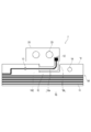
- FIG. 10 is a diagram for explaining a main part of the battery module of the third embodiment.
- the bus bar 27 has a terminal engaging portion 27a that engages with the terminals of the battery 3A to the battery 3L.
- the terminal engaging portion 27a has substantially the same configuration as the bus bar 20 of the first embodiment and the second embodiment, and is a plate-shaped metal member provided with a hole 23.
- the bus bar 27 has a protruding end portion 27b extending from the terminal engaging portion 27a toward the longitudinal extending portion 58.
- the tip portion 27b overlaps the electrode 12 and is electrically conductive with the wiring 11.
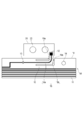
- FIG. 11 is a diagram for explaining a modified example of the battery module of FIG.
- the battery module shown in FIG. 11 is different from the configuration shown in FIG. 10 in that the protruding end portion 27b is arranged under the longitudinal extending portion 58.
- the tip portion 27b is formed of an insulating flexible substrate 10. Therefore, a hole (not shown) is formed in the base film portion of the flexible substrate 10 under the electrode 12 in the tip portion 27b, and the electrode 12 conducts with the tip portion 27b through this hole.
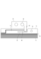
- FIG. 12 (a) and 12 (b) are views for explaining the main parts of the battery module of the fourth embodiment, and FIG. 12 (a) shows the upper surface of the main body portion 68 of the battery module as viewed from above.
- FIG. 12 (b) is a diagram showing the back surface of the main body portion 68 shown in FIG. 12 (a).
- the battery module of the fourth embodiment is configured such that the flexible substrate 10 covers the bus bar 20.
- the flexible substrate 10 since the flexible substrate 10 has an insulating property, it is necessary to form a contact hole at a portion of the connecting portion 38 corresponding to the electrode 12 and electrically connect the wiring 11 and the bus bar 20.
- the flexible substrate 10 maintains the insulation between the flexible substrate 10 and the bus bar 20, and the battery module can be operated normally. Since the battery modules of FIGS. 12 (a) and 12 (b) can increase the degree of freedom in routing the wiring 11, the layout and design of the circuit become easy.
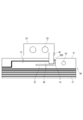
- FIGS. 13 (a) and 13 (b) are views for explaining a modified example of the fourth embodiment
- FIG. 13 (a) is a top view and a view of the main body portion 68 of the modified example as viewed from above.
- 13 (b) is a diagram showing the back surface of the main body portion 68 shown in FIG. 13 (a).
- the bus bar 29 is used instead of the bus bar 20.
- the bus bar 29 is a bus bar having a conductor portion further outside the hole 23 of the bus bar 20.
- the connecting portion 88 is formed by the longitudinal extending portion 88a and the cross extending portion 88b, and the slit 89 is formed on the entire circumference of the connecting portion 88. ..
- a narrow connection in which a plurality of batteries arranged in one direction are connected to each other via a bus bar, and the batteries are a wiring material including a flexible substrate whose arrangement direction is the longitudinal direction, and are connected to the bus bar. It has a portion and a main body portion that is connected to the connection portion and includes a portion wider than the connection portion, and the connection portion protrudes from the main body portion in the longitudinal direction and is along the longitudinal direction. Wiring material with an extending longitudinal extension.
- the flexible substrate has a plurality of the connection portions, has at least one substrate unit for each of the connection portion and a main body portion that is divided corresponding to the connection portion, and the longitudinal extension portion ,
- the wiring material of (1) protruding from the main body portion of the corresponding substrate unit.
- the wiring material of (2), wherein the longitudinal extension portion is arranged in a circumscribed virtual area circumscribing the main body portion of the corresponding substrate unit.
- the wiring material of (3), wherein the longitudinal extending portion is arranged so as to be included in the circumscribed virtual area.
- the connection portion has a cross extension portion that extends from the longitudinal extension portion in a direction intersecting the longitudinal direction and connects to the bus bar, and the length of the longitudinal extension portion is the cross extension. Any one of the wiring materials (1) to (6) that is longer than the protrusion.
- a plurality of batteries arranged in one direction are connected to each other via a bus bar, and a wiring material including a flexible substrate in which the arrangement direction of the batteries is longitudinal is provided, and the wiring material is connected to the bus bar.
- connection portion has a narrow connection portion and a main body portion that is connected to the connection portion and includes a portion wider than the connection portion, and the connection portion protrudes from the main body portion in the longitudinal direction and is in the longitudinal direction.
- the bus bar has a terminal engaging portion that engages with the terminal of the battery and a protruding portion that extends from the terminal engaging portion toward the longitudinal extending portion.
- Battery module (9) The battery module of (8), wherein the flexible substrate covers the bus bar.
Landscapes
- Chemical & Material Sciences (AREA)
- Chemical Kinetics & Catalysis (AREA)
- Electrochemistry (AREA)
- General Chemical & Material Sciences (AREA)
- Engineering & Computer Science (AREA)
- Manufacturing & Machinery (AREA)
- Connection Of Batteries Or Terminals (AREA)
- Battery Mounting, Suspending (AREA)
Abstract
フレキシブル基板の耐震性を確保しつつ、省スペース化に有利な配線材を提供す る。 一方向に配列された複数のバッテリ3A~3Lをバスバー20を介して互いに接続し、バッテリ3A~3Lの配列方向が長手方向のフレキシブル基板10を含む配線材7を、バスバー20と接続する細幅の接続部18と、接続部18と接続されて接続部18より太幅の部分を含む本体部68と、により構成し、接続部18を、本体部68から長手方向に突出し、かつ長手方向に沿って延びる長手延出部18aを有するように構成する。
Description
本発明は、配線材及びバッテリモジュールに関する。
複数のバッテリをケース体に収容したバッテリモジュールがある。バッテリモジュールでは、ケース体内で配線によりバッテリと導電端子(バスバー)とを電気的に接続してバッテリ電圧を監視する。また、バッテリモジュールでは、振動が加わった場合に複数のバッテリ間を接続する配線が切れる、あるいは捩れる等してバッテリ間の電気的な接続に異常が生じることを防ぐため、配線の基板に可撓性を有するフレキシブル基板が用いられる。このとき、配線に耐震性を付与するため、フレキシブル基板は、バッテリと接続する配線下の長さに余裕を持たせ、振動に対して撓むように設計される。このような構成のバッテリモジュールは、例えば、特許文献1、特許文献2に記載されている。
しかしながら、バッテリモジュールは、配置スペース等の関係から小型であることが好ましく、ケース体はバッテリの収容に必要な寸法形状を有するものの、配線の引き回しや配線下のフレキシブル基板の設計が制限されている。上記の特許文献1、特許文献2は、いずれもバスバーと接続するフレキシブル基板の部分(接続部分)がフレキシブル基板の本体から幅方向に突出するため、接続部分が撓み易いようにするにはケース体のサイズが幅方向に大きくなり、バッテリモジュールの小型化に不利であった。
本発明は、このような点に鑑みてなされたものであり、フレキシブル基板の耐震性を確保しつつ、省スペース化に有利な配線材及びバッテリモジュールに関する。
本発明は、このような点に鑑みてなされたものであり、フレキシブル基板の耐震性を確保しつつ、省スペース化に有利な配線材及びバッテリモジュールに関する。
本発明の配線材の一態様は、一方向に配列された複数のバッテリを、バスバーを介して互いに接続し、前記バッテリの配列方向が長手方向のフレキシブル基板を含む配線材であって、前記バスバーと接続する細幅の接続部と、前記接続部と接続されて前記接続部より太幅の部分を含む本体部と、を有し、前記接続部は、前記本体部から前記長手方向に突出し、かつ前記長手方向に沿って延びる長手延出部を有する、配線材。
本発明のバッテリモジュールの一態様は、一方向に配列された複数のバッテリを、バスバーを介して互いに接続し、前記バッテリの配列方向が長手方向のフレキシブル基板を含む配線材を備え、
前記配線材は、前記バスバーと接続する細幅の接続部と、前記接続部と接続されて前記接続部より太幅の部分を含む本体部と、を有し、前記接続部は前記本体部から前記長手方向に突出し、かつ前記長手方向に沿って延びる長手延出部を有し、
前記バスバーは、前記バッテリの端子と係り合う端子係合部と、前記端子係合部から前記長手延出部に向かって延びる突端部と、を有する、バッテリモジュール。
前記配線材は、前記バスバーと接続する細幅の接続部と、前記接続部と接続されて前記接続部より太幅の部分を含む本体部と、を有し、前記接続部は前記本体部から前記長手方向に突出し、かつ前記長手方向に沿って延びる長手延出部を有し、
前記バスバーは、前記バッテリの端子と係り合う端子係合部と、前記端子係合部から前記長手延出部に向かって延びる突端部と、を有する、バッテリモジュール。
本発明は、フレキシブル基板の耐震性を確保しつつ、省スペース化に有利な配線材及びバッテリモジュールを提供することができる。
本発明の第一実施形態から第四実施形態の配線材及びバッテリモジュールを以下に説明する。なお、本実施形態において同一部材は同一の符号を付して示す。また、本実施形態の図面は、本発明の構成、各部材の位置関係や形状を例示するものであって、その具体的な構成を限定するものではなく、また、寸法形状、縦横比を必ずしも正確に示すものではない。
(概要)
図1及び図2は、第一実施形態のバッテリモジュール1及び配線材7を説明するための図である。図1は、第一実施形態のバッテリモジュール1の上面視を示す図である。図2は、図1に示す配線材7の要部を説明するための図である。
バッテリモジュール1は、複数のバッテリ3Aからバッテリ3Lを配線材7によってそれぞれ接続して構成されている。配線材7は、フレキシブル基板10と、フレキシブル基板10上に形成された配線11とを含んでいる。バッテリ3Aからバッテリ3Lの端子33にはバスバー20が機械的、電気的に接続していて、配線11がバスバー20に接続し、さらにコネクタ25に接続されている。バッテリ3Aからバッテリ3Lは直線方向に並べて配置され、各々の端子33から得られた電圧値(信号)がコネクタ25から図示しない基板に形成された図示しない回路に入力される。回路は、例えばバッテリ3Aからバッテリ3Lの電圧値の検知や温度センサ等を構成する。図1に示すバッテリモジュール1は、図中のx方向にバッテリ3Aからバッテリ3Lを並べて配置しており、x方向に長くなるように構成されている。換言すると、フレキシブル基板10は、x方向が長手方向になっている。
図1に示すバッテリモジュール1は、図示しないケース体に収容されて使用される。ケース体内において、配線材7は振動が加わったことによる破断を防ぐために振動を吸収して撓む部分を有している。撓み部分はその長さが長い方が振動の吸収効果が高いことが知られている。しかし、ケース体内部のスペースには制限があり、撓み部分には省スペース化と振動吸収の相反する二つの点が要求される。
本発明の第一実施形態から第四実施形態は、いずれも図2に示すように、フレキシブル基板10に切欠き部100を形成し、切欠き部100内に接続部18の撓み部分として作用する長手延出部18aを配置している。
本発明の第一実施形態から第四実施形態は、いずれも図2に示すように、フレキシブル基板10に切欠き部100を形成し、切欠き部100内に接続部18の撓み部分として作用する長手延出部18aを配置している。
また、第一実施形態から第四実施形態は、いずれも長手延出部18aをフレキシブル基板10の長手方向に沿って延出させて、フレキシブル基板10が幅方向に突出する部分を極力少なくしている。
このようにすれば、配線材7の配置スペース内に長手延出部18aを配置できるので、長手延出部18aの配置スペースを別に設けることがなく、長手延出部18aの長さを充分な耐震性を確保できる程度に長くすることが可能である。
このようにすれば、配線材7の配置スペース内に長手延出部18aを配置できるので、長手延出部18aの配置スペースを別に設けることがなく、長手延出部18aの長さを充分な耐震性を確保できる程度に長くすることが可能である。
[第一実施形態]
以下、第一実施形態のバッテリモジュール1及び配線材7について詳細に説明する。
(バッテリモジュール)
図1に示すように、バッテリモジュール1は、一方向に配列された複数のバッテリ(バッテリ3Aからバッテリ3L)を、バスバー20を介して互いに接続し、3Aからバッテリ3Lの配列方向が長手方向のフレキシブル基板10を含む配線材7と、配線材7と接続されるバスバー20と、を備えている。バスバー20に形成されている孔23は、バッテリ3A等を固定するためのネジが挿通される挿通孔である。配線材7において、バッテリ3Aからバッテリ3Lのうちの少なくとも一部のバッテリを接続するフレキシブル基板10は、バスバー20と接続する細幅の接続部18と、接続部18と接続されて接続部18より太幅の部分を含む本体部68と、を備えている。そして、図2に示すように、接続部18は、本体部68から長手方向に突出し、かつ長手方向に沿って延びる長手延出部18aを有している。
第一実施形態では、フレキシブル基板10が、接続部18を複数有している。フレキシブル基板10は、接続部18と、この接続部18に対応して区分けされる本体部分68aから本体部分68kとをそれぞれ少なくとも一つ含む基板ユニットP1から基板ユニットP11を有している。換言すると、本体部分68a~68kは、本体部68を接続部18に対応つけて区分けされた各部分であり、接続部18と、この接続部18に対応する本体部分の組み合わせが基板ユニット(基板ユニットP1から基板ユニットP11のいずれか一つ)である。
図1に示す配線材7には、基板ユニットP1から基板ユニットP11が含まれている。なお、図1に示した例では、ヒューズ13に向かって屈曲する配線11のパターンに合わせて本体部68を区切って本体部分68a~68kとし、各本体部分と、この本体部分に接続された一つの接続部18とを一つの基板ユニットとしている。
長手延出部18aは、対応する基板ユニットの本体部分から突出する。長手延出部18aと対応する基板ユニットの本体部分とは、長手延出部18aと同一の基板ユニットに含まれる本体部分をいい、例えば、基板ユニットP3の長手延出部18aに対応する本体部分は本体部分68cである。
図1に示す配線材7には、基板ユニットP1から基板ユニットP11が含まれている。なお、図1に示した例では、ヒューズ13に向かって屈曲する配線11のパターンに合わせて本体部68を区切って本体部分68a~68kとし、各本体部分と、この本体部分に接続された一つの接続部18とを一つの基板ユニットとしている。
長手延出部18aは、対応する基板ユニットの本体部分から突出する。長手延出部18aと対応する基板ユニットの本体部分とは、長手延出部18aと同一の基板ユニットに含まれる本体部分をいい、例えば、基板ユニットP3の長手延出部18aに対応する本体部分は本体部分68cである。
図1に示すバッテリモジュール1は、複数の基板ユニットP1から基板ユニットP11によりバッテリ3Bからバッテリ3Lが接続されている。バッテリの両端に配置されたバッテリを接続するフレキシブル基板10の部分は、配線の終端等に適するように任意の形状を有するものであってもよい。図1に示す例では、配線材7の端部eのバスバー21は、バッテリ3A、3Lと直接接続されている。
上記構成において、細幅とは、接続部18の延出方向に直交する方向の長さ(幅)が本体部68に比して短いことをいう。接続部18より太幅の部分を含む本体部68とは、フレキシブル基板10のうちの接続部18の基端と接続されて、かつ接続部18の幅より幅広の部分を含むものであればよい。第一実施形態の本体部68は、具体的には図1に示す幅W以上の幅を有する部位を指す。
(配線材)
図2に示すように、配線材7は、フレキシブル基板10を含んでいる。バッテリ3Aからバッテリ3Lまでを接続するフレキシブル基板10は、接続部18と、本体部68を備えている。また、接続部18は、本体部68からフレキシブル基板10の長手方向(図1中のx方向)に沿って突出し、かつ延びる長手延出部18aを有している。接続部18と本体部68との間には、スリット15が形成されて、接続部18は本体部68に規制されることなく自由に浮き上がる、屈曲する、あるいは捻じれるように変位することができる。本明細書では、このような変位を総称して「撓む」とも記す。
図2に示すように、配線材7は、フレキシブル基板10を含んでいる。バッテリ3Aからバッテリ3Lまでを接続するフレキシブル基板10は、接続部18と、本体部68を備えている。また、接続部18は、本体部68からフレキシブル基板10の長手方向(図1中のx方向)に沿って突出し、かつ延びる長手延出部18aを有している。接続部18と本体部68との間には、スリット15が形成されて、接続部18は本体部68に規制されることなく自由に浮き上がる、屈曲する、あるいは捻じれるように変位することができる。本明細書では、このような変位を総称して「撓む」とも記す。
図2に示す長手延出部18aは、図1に示す外接仮想領域200に配置される。外接仮想領域200は、フレキシブル基板10の本体部分68a~68kの各々に外接する仮想的な領域である。本体部分68a~68kの外接仮想領域200をまとめた全体は、本体部68の配置に必要なスペースと大凡一致している。この点から、第一実施形態では、長手延出部18aを配置するためのスペースを別途設ける必要がないことが分かる。
なお、図1において、外接仮想領域200を示す点線の一部は視認性を考慮して正確に外接する線とわずかにずらして示している。
なお、図1において、外接仮想領域200を示す点線の一部は視認性を考慮して正確に外接する線とわずかにずらして示している。
また、接続部18は、長手延出部18aから長手方向と交差する方向に延出する交差延出部18bを有している。第一実施形態では、長手延出部18aの長さを交差延出部18bより長くし、振動に対して撓む部分を確保しながら接続部18において配線材7の幅方向の配置スペースを小さくしている。第一実施形態においては、交差延出部18bがバスバー20と接続するための最小長さになっていて、配線材7にバスバー20を近接させて配置することができる。
また、フレキシブル基板10上に形成される配線11は、途中にヒューズ13を有し、バッテリモジュール1において過電流が流れることに備えている。配線11の端部には電極12が形成されている。第一実施形態では、電極12を半田材料によりバスバー20に接続している。このため、交差延出部18bのバスバー20と重なる端部には図示しない孔が形成されていて、孔を介して半田材料により配線11とバスバー20とが機械的、電気的に接続される。また、配線11の他方の端部は、コネクタ25(図1)に接続されている。フレキシブル基板10には配線材7をバッテリに接続する際に使用される位置合わせ孔14が形成されている。
ただし、第一実施形態は、配線11とバスバー20とを半田により接続することに限定されるものでなく、半田の他、レーザ溶接、超音波接合、リベット接続等によって配線11をバスバー20に接続してもよい。
フレキシブル基板10は、例えば、薄膜状の絶縁体であるベースフィルム上に配線11を形成して製造される。配線11は端子部や半田付けがされる部分を除いて絶縁体シートにより保護されている。ベースフィルムにはポリイミドやポリエステル(ポリエチレンナフタレート(PEN)、液晶ポリマー(LCP))等のプラスチック樹脂が使用される。導体には銅あるいは銅箔が使用される。接着剤にはエポキシ系の樹脂やアクリル樹脂が使用される。バスバー20は、例えば銅、真鍮、アルミニウム等の導電率の高い材料で形成される。
以上の構成によれば、第一実施形態は、配線材7の配置スペースを小さくすることができる。また、第一実施形態は、小さいスペース内にバッテリ3Aからバッテリ3Lを配置することによって電池容量を高めることに有利である。
また、本体部68から延出する部分を設けたフレキシブル基板10は、振動が加わった場合、本体部68に延出方向の亀裂が生じる可能性がある。このため、例えば交差延出部18bを直接本体部68に接続させた場合、配線11と交差する方向に亀裂が生じて配線11を断線させる可能性がある。一方、長手延出部18aを設けた第一実施形態の配線材7では、長手延出部18aの基端にx方向(図1)の亀裂が生じても、この亀裂が配線11と交差し難く、亀裂によって配線11が断線する範囲を小さくすることができる。
また、本体部68から延出する部分を設けたフレキシブル基板10は、振動が加わった場合、本体部68に延出方向の亀裂が生じる可能性がある。このため、例えば交差延出部18bを直接本体部68に接続させた場合、配線11と交差する方向に亀裂が生じて配線11を断線させる可能性がある。一方、長手延出部18aを設けた第一実施形態の配線材7では、長手延出部18aの基端にx方向(図1)の亀裂が生じても、この亀裂が配線11と交差し難く、亀裂によって配線11が断線する範囲を小さくすることができる。
図3は、第一実施形態の変形例を説明するための図である。図3に示す配線材は、図2に示す配線材7に、さらにジョイント部19a、ジョイント部19bを設けたものである。ジョイント部19a、19bは、接続部18と本体部68とを、接続部18が破断することに要する力よりも小さい力で破断可能な部材である。
「接続部18が破断することに要する力」とは、部材を破断させるために必要な引張荷重または力をいう。引張試験において破断強度と破断荷重は類似している。シート状のフレキシブル基板10では、破断強度が力をシート幅で除算した値(kgf/mm)により表される。
第一実施形態では、ジョイント部19a、19bをいずれも接続部18と同様のフレキシブル基板10により形成しているため、ジョイント部19a、19bの幅を接続部18の幅より細くすることによってジョイント部19a、19bの破断強度を接続部18よりも低くすることができる。
「接続部18が破断することに要する力」とは、部材を破断させるために必要な引張荷重または力をいう。引張試験において破断強度と破断荷重は類似している。シート状のフレキシブル基板10では、破断強度が力をシート幅で除算した値(kgf/mm)により表される。
第一実施形態では、ジョイント部19a、19bをいずれも接続部18と同様のフレキシブル基板10により形成しているため、ジョイント部19a、19bの幅を接続部18の幅より細くすることによってジョイント部19a、19bの破断強度を接続部18よりも低くすることができる。
上記構成によれば、バッテリモジュール1に配線材を組付ける際には接続部18がジョイント部19a、19bにより本体部68に接続されていて、接続部18をバスバー20に接続する作業が容易になる。また、配線材の組付け後、フレキシブル基板10に荷重が加わった場合には接続部18よりも先にジョイント部19a、19bが破断する。ジョイント部19a、19bが破断すると、長手延出部18aが自由に撓むようになって振動を吸収し、接続部18は破断し難くなる。つまり、図3に示すジョイント部19a、19bは、配線材の組み付け作業の効率性と、組付け後の破断の防止とを両立させることができる。
ただし、第一実施形態のジョイント部は、図3に示す構成に限定されるものではない。例えば、ジョイント部は、ジョイント部19a、19bのように一定の幅を有するものに限定されず、さらに破断させたい個所の幅を特に細くするようにしてもよい。また、ジョイント部は、接続部18と同様の部材の幅を細く加工するものに限定されず、接続部18よりも破断強度の低い部材によって接続部18を本体部68に固定しておくものであってもよい。
図4は、第一実施形態の配線材の他の変形例を説明するための図である。図4に示す接続部38は、長手延出部38aは、長手方向に延出すると共に長手方向と交差する方向の凹凸を有するミアンダ形状である。なお、長手延出部38aは、図1中のx方向に沿って延出した後、比較的緩やかにバスバー20に向かい、図1中のy方向に沿って延出する。第一実施形態では、接続部38のうちのy方向に沿う部分を交差延出部38bとし、本体部68から交差延出部38bに至るまでの接続部38の部分を長手延出部38aとする。
図4に示す接続部38は、一定の幅を有し、外縁が湾曲していることによって外縁が直線の接続部18よりも力が非一様に作用する。このため、接続部38は、接続部18よりも撓み易くなって高い破断防止効果を得ることができる。なお、図4に示す配線材は、図3に示す配線材と同様にジョイント部19a、19bを備えていて、バッテリモジュール1への組み付け作業時には長手延出部38aが本体部68に固定されていて、荷重の印加時にはジョイント部19a、19bが切り離されてスリット35により本体部68から離れて撓むようになる。このことにより、ジョイント部19a、19bを備える接続部38は、組付けの作業性と破断防止とを両立させることができる。
[第二実施形態]
次に、第二実施形態の配線材を説明する。図5及び図6は、第二実施形態の配線材を説明するための図である。第二実施形態の配線材は、第一実施形態が長手延出部と交差延出部の両方をフレキシブル基板10により形成しているのに対し、交差延出部を長手延出部と異なる導電性部材により形成する点で第一実施形態と相違する。第二実施形態の例では、導電性部材をウェルディング・プレート(welding plate)42としている。
図5に示す配線材では、長手延出部48に配線11が形成されていて、配線11とバスバー20とをウェルディング・プレート42が電気的、機械的に接続している。バスバー20とウェルディング・プレート42の接続は、溶接によって行われる。交差延出部を長手延出部と別体とする第二実施形態は、長手延出部18aと交差延出部18bとが一体の接続部18を構成するものよりも配線材を組み付ける作業が容易である。
図6は、第二実施形態において、長手延出部48よりも破断強度が低いジョイント部49を設けた配線材を示している。交差延出部を別体のウェルディング・プレート42とする第二実施形態では、ジョイント部49が長手延出部48と本体部68とを接続する。このような構成によれば、配線材の組み付け時には長手延出部48が本体部68に固定されているので作業がし易く、荷重が加わった際にはジョイント部49が破断して長手延出部48が撓むようにすることができる。
また、図5、図6に示す長手延出部48は、第一実施形態の接続部18と同様に、本体部分を内包する外接仮想領域200の内部に設けられている。このとき、図5、図6に示す第二実施形態の長手延出部48は、バスバー20の側の外縁が外接仮想領域200の外縁と一致して長手延出部48の周辺の一部と本体部68との間にスリット15が生じている。しかし、第二実施形態は、このような構成に限定されず、長手延出部48を外接仮想領域200のさらに内側に設けるようにしてもよい。
図7は、第二実施形態の変形例であって、長手延出部48を外接仮想領域200に内包されるように配置した配線材の例を示す図である。図7に示す配線材は、長手延出部48の全周にスリット15が形成されて、長手延出部48とバスバー20との間に配線11が形成された本体部68が配置される。図7に示す配線材は、図5、図6に示す配線材よりも配線11の引き回しの自由度を高めることができて、配線11の設計やレイアウトが容易になる。
図8は、ミアンダ形状の長手延出部58を外接仮想領域200に内包されるように形成した例を示す図である。図8に示す配線材においても、長手延出部58の全周にスリット35が形成される。そして、長手延出部58とバスバー20との間には本体部68が配置され、長手延出部58とバスバー20との間の本体部68に配線11を形成できるようになる。
図8は、ミアンダ形状の長手延出部58を外接仮想領域200に内包されるように形成した例を示す図である。図8に示す配線材においても、長手延出部58の全周にスリット35が形成される。そして、長手延出部58とバスバー20との間には本体部68が配置され、長手延出部58とバスバー20との間の本体部68に配線11を形成できるようになる。
さらに、図7、図8に示すように、長手延出部の全周にスリット35が形成される配線材は、長手延出部の片側にのみスリットが形成されるものよりもスリット35から長手方向の亀裂が生じ易くなる。
図9は、上記の点に考慮して、亀裂防止用の部材を設けた例を示している。図9に示す配線材は、スリット35の近傍にダミーパターン131a、ダミーパターン131bを備えている。第二実施形態では、ダミーパターン131a、131bを形成するにあたり、配線11を形成する工程において配線11と同様の材料により同時に形成することができる。
図9は、上記の点に考慮して、亀裂防止用の部材を設けた例を示している。図9に示す配線材は、スリット35の近傍にダミーパターン131a、ダミーパターン131bを備えている。第二実施形態では、ダミーパターン131a、131bを形成するにあたり、配線11を形成する工程において配線11と同様の材料により同時に形成することができる。
[第三実施形態]
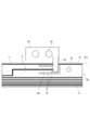
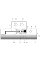
次に、第三実施形態のバッテリモジュールを説明する。図10は、第三実施形態のバッテリモジュールの要部を説明するための図である。図10に示すように、バスバー27は、バッテリ3Aからバッテリ3Lの端子と係り合う端子係合部27aを有している。端子係合部27aは、第一実施形態、第二実施形態のバスバー20と実質的に同様の構成であって、孔23を備える板状の金属部材である。また、バスバー27は、端子係合部27aから長手延出部58に向かって延びる突端部27bを有している。突端部27bは、電極12上に重なって配線11と電気的に導通している。
次に、第三実施形態のバッテリモジュールを説明する。図10は、第三実施形態のバッテリモジュールの要部を説明するための図である。図10に示すように、バスバー27は、バッテリ3Aからバッテリ3Lの端子と係り合う端子係合部27aを有している。端子係合部27aは、第一実施形態、第二実施形態のバスバー20と実質的に同様の構成であって、孔23を備える板状の金属部材である。また、バスバー27は、端子係合部27aから長手延出部58に向かって延びる突端部27bを有している。突端部27bは、電極12上に重なって配線11と電気的に導通している。
図11は、図10のバッテリモジュールの変形例を説明するための図である。図11に示すバッテリモジュールは、長手延出部58の下に突端部27bが配置されている点で図10に示す構成と異なっている。突端部27bは絶縁性のフレキシブル基板10で形成されている。このため、突端部27bのうちの電極12下のフレキシブル基板10のベースフィルムの部分に図示しない孔が形成されており、電極12はこの孔を通して突端部27bと導通する。
[第四実施形態]
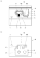
図12(a)、図12(b)は、第四実施形態のバッテリモジュールの要部を説明するための図であって、図12(a)はバッテリモジュールの本体部68を上方からみた上面図、図12(b)は、図12(a)に示す本体部68の裏面を示す図である。第四実施形態のバッテリモジュールは、フレキシブル基板10がバスバー20を覆うように構成される。第四実施形態のバッテリモジュールは、フレキシブル基板10が絶縁性を有するので、接続部38の電極12に当たる部位にコンタクト孔を形成し、配線11とバスバー20とを電気的に接続する必要がある。また、バスバー20上に配線11を引き回してもフレキシブル基板10はフレキシブル基板10とバスバー20との間の絶縁性を保ち、バッテリモジュールを正常に稼動させることができる。
図12(a)、図12(b)のバッテリモジュールは、配線11の引き回しの自由度を高めることができるので、回路のレイアウトや設計が容易になる。
図13(a)、図13(b)は、第四実施形態の変形例を説明するための図であって、図13(a)は変形例の本体部68を上方からみた上面図、図13(b)は、図13(a)に示す本体部68の裏面を示す図である。図13(a)、図13(b)に示すバッテリモジュールでは、バスバー20に代えてバスバー29を使用する。バスバー29は、バスバー20の孔23のさらに外側に導体部分が存在するバスバーである。バスバー29を用いることにより、第四実施形態は、バスバー29をフレキシブル基板10で覆い、バスバー29に対して二方から電極12を接続してバッテリの電位を検知することができる。
また、第四実施形態では、図13に示すバッテリモジュールにおいても長手延出部88aと交差延出部88bとによって接続部88を構成し、接続部88の全周にスリット89を形成している。
また、第四実施形態では、図13に示すバッテリモジュールにおいても長手延出部88aと交差延出部88bとによって接続部88を構成し、接続部88の全周にスリット89を形成している。
上記実施形態は、以下の技術思想を包含するものである。
(1)一方向に配列された複数のバッテリを、バスバーを介して互いに接続し、前記バッテリの配列方向が長手方向のフレキシブル基板を含む配線材であって、前記バスバーと接続する細幅の接続部と、前記接続部と接続されて前記接続部より太幅の部分を含む本体部と、を有し、前記接続部は、前記本体部から前記長手方向に突出し、かつ前記長手方向に沿って延びる長手延出部を有する、配線材。
(2) 前記フレキシブル基板は、前記接続部を複数有し、前記接続部と当該接続部に対応して区分けされる本体部分とをそれぞれ少なくとも一つ基板ユニットを有し、前記長手延出部は、対応する前記基板ユニットの前記本体部分から突出する、(1)の配線材。
(3)前記長手延出部は、対応する前記基板ユニットの前記本体部分に外接する外接仮想領域に配置される、(2)の配線材。
(4)前記長手延出部は、前記外接仮想領域に内包されるように配置される、(3)の配線材。
(5)前記接続部と前記本体部とを、前記接続部が破断することに要する力よりも小さい力により破断可能なジョイント部をさらに備える、(1)から(4)のいずれか一つの配線材。
(6)前記長手延出部は、前記長手方向に延出すると共に前記長手方向と交差する方向の凹凸を有するミアンダ形状である、(1)から(5)のいずれか一つの配線材。
(7)前記接続部は、前記長手延出部から前記長手方向と交差する方向に延出して前記バスバーと接続する交差延出部を有し、前記長手延出部の長さは前記交差延出部より長い、(1)から(6)のいずれか一つの配線材。
(8)一方向に配列された複数のバッテリを、バスバーを介して互いに接続し、前記バッテリの配列方向が長手方向のフレキシブル基板を含む配線材を備え、前記配線材は、前記バスバーと接続する細幅の接続部と、前記接続部と接続されて前記接続部より太幅の部分を含む本体部と、を有し、前記接続部は前記本体部から前記長手方向に突出し、かつ前記長手方向に沿って延びる長手延出部を有し、前記バスバーは、前記バッテリの端子と係り合う端子係合部と、前記端子係合部から前記長手延出部に向かって延びる突端部と、を有する、バッテリモジュール。
(9)前記フレキシブル基板が前記バスバーを覆っている、(8)のバッテリモジュール。
1・・・バッテリモジュール
3A~3L・・・バッテリ
7・・・配線材
10・・・フレキシブル基板
11・・・配線
12・・・電極
13・・・ヒューズ
14・・・位置合わせ孔
15、35、89・・・スリット
18、38・・・接続部
18a、38a、48、58、88a・・・長手延出部
18b、38b、88b・・・交差延出部
19a、19b、49・・・ジョイント部
20、21、27・・・バスバー
23・・・孔
25・・・コネクタ
27a・・・端子係合部
27b・・・突端部
33・・・端子
131a、131b・・・ダミーパターン
42・・・ウェルディング・プレート
68・・・本体部
68a~68k・・・本体部分
100・・・切欠き部
200・・・外接仮想領域
e・・・端部
P1~P11・・・基板ユニット
Claims (9)
- 一方向に配列された複数のバッテリを、バスバーを介して互いに接続し、前記バッテリの配列方向が長手方向のフレキシブル基板を含む配線材であって、
前記バスバーと接続する細幅の接続部と、前記接続部と接続されて前記接続部より太幅の部分を含む本体部と、を有し、
前記接続部は、前記本体部から前記長手方向に突出し、かつ前記長手方向に沿って延びる長手延出部を有する、配線材。 - 前記フレキシブル基板は、前記接続部を複数有し、前記接続部と当該接続部に対応して区分けされる本体部分とをそれぞれ少なくとも一つ基板ユニットを有し、
前記長手延出部は、対応する前記基板ユニットの前記本体部分から突出する、請求項1に記載の配線材。 - 前記長手延出部は、対応する前記基板ユニットの前記本体部分に外接する外接仮想領域に配置される、請求項2に記載の配線材。
- 前記長手延出部は、前記外接仮想領域に内包されるように配置される、請求項3に記載の配線材。
- 前記接続部と前記本体部とを、前記接続部が破断することに要する力よりも小さい力により破断可能なジョイント部をさらに備える、請求項1から4のいずれか一項に記載の配線材。
- 前記長手延出部は、前記長手方向に延出すると共に前記長手方向と交差する方向の凹凸を有するミアンダ形状である、請求項1から5のいずれか一項に記載の配線材。
- 前記接続部は、前記長手延出部から前記長手方向と交差する方向に延出して前記バスバーと接続する交差延出部を有し、前記長手延出部の長さは前記交差延出部より長い、請求項1から6のいずれか一項に記載の配線材。
- 一方向に配列された複数のバッテリを、バスバーを介して互いに接続し、前記バッテリの配列方向が長手方向のフレキシブル基板を含む配線材を備え、
前記配線材は、前記バスバーと接続する細幅の接続部と、前記接続部と接続されて前記接続部より太幅の部分を含む本体部と、を有し、前記接続部は前記本体部から前記長手方向に突出し、かつ前記長手方向に沿って延びる長手延出部を有し、
前記バスバーは、前記バッテリの端子と係り合う端子係合部と、前記端子係合部から前記長手延出部に向かって延びる突端部と、を有する、バッテリモジュール。 - 前記フレキシブル基板が前記バスバーを覆っている、請求項8に記載のバッテリモジュール。
Priority Applications (3)
| Application Number | Priority Date | Filing Date | Title |
|---|---|---|---|
| DE112020002758.9T DE112020002758T5 (de) | 2019-06-07 | 2020-03-18 | Verdrahtungsmaterial und Batteriemodul |
| US17/299,881 US20220077536A1 (en) | 2019-06-07 | 2020-03-18 | Wiring material and battery module |
| CN202080006751.8A CN113169402A (zh) | 2019-06-07 | 2020-03-18 | 布线部件及电池模块 |
Applications Claiming Priority (2)
| Application Number | Priority Date | Filing Date | Title |
|---|---|---|---|
| JP2019107124A JP7403240B2 (ja) | 2019-06-07 | 2019-06-07 | 配線材及びバッテリモジュール |
| JP2019-107124 | 2019-06-07 |
Publications (1)
| Publication Number | Publication Date |
|---|---|
| WO2020246111A1 true WO2020246111A1 (ja) | 2020-12-10 |
Family
ID=73652557
Family Applications (1)
| Application Number | Title | Priority Date | Filing Date |
|---|---|---|---|
| PCT/JP2020/011869 WO2020246111A1 (ja) | 2019-06-07 | 2020-03-18 | 配線材及びバッテリモジュール |
Country Status (5)
| Country | Link |
|---|---|
| US (1) | US20220077536A1 (ja) |
| JP (1) | JP7403240B2 (ja) |
| CN (1) | CN113169402A (ja) |
| DE (1) | DE112020002758T5 (ja) |
| WO (1) | WO2020246111A1 (ja) |
Cited By (2)
| Publication number | Priority date | Publication date | Assignee | Title |
|---|---|---|---|---|
| WO2022158510A1 (ja) * | 2021-01-22 | 2022-07-28 | 株式会社オートネットワーク技術研究所 | 配線モジュール |
| FR3121516A1 (fr) * | 2021-04-02 | 2022-10-07 | Tyco Electronics (Shanghai) Co., Ltd. | Ensemble de connexion électrique et dispositif d'acquisition de signal de bloc-batterie |
Families Citing this family (5)
| Publication number | Priority date | Publication date | Assignee | Title |
|---|---|---|---|---|
| US20220394856A1 (en) * | 2019-10-31 | 2022-12-08 | Autonetworks Technologies, Ltd. | Flexible printed circuit board including terminal, wiring module, and power storage module |
| CN114583401A (zh) * | 2020-12-02 | 2022-06-03 | 莫仕连接器(成都)有限公司 | 电池连接模块 |
| JP7271499B2 (ja) * | 2020-12-21 | 2023-05-11 | プライムプラネットエナジー&ソリューションズ株式会社 | 蓄電モジュール |
| JP2022176478A (ja) * | 2021-05-17 | 2022-11-30 | 株式会社オートネットワーク技術研究所 | 配線モジュール、および蓄電モジュール |
| WO2023159397A1 (zh) * | 2022-02-23 | 2023-08-31 | 宁德时代新能源科技股份有限公司 | 电池的线缆类连接件保护装置、电池以及用电装置 |
Citations (9)
| Publication number | Priority date | Publication date | Assignee | Title |
|---|---|---|---|---|
| JP2013054940A (ja) * | 2011-09-05 | 2013-03-21 | Toyota Motor Corp | 電池接続ユニット及び電源装置 |
| JP2013080621A (ja) * | 2011-10-04 | 2013-05-02 | Auto Network Gijutsu Kenkyusho:Kk | 電池用配線モジュール |
| JP2013098032A (ja) * | 2011-11-01 | 2013-05-20 | Auto Network Gijutsu Kenkyusho:Kk | 電圧検知端子の接続構造 |
| JP2017033646A (ja) * | 2015-07-29 | 2017-02-09 | 株式会社豊田自動織機 | 電池モジュールの製造方法 |
| CN206211098U (zh) * | 2016-12-06 | 2017-05-31 | 泰科电子(上海)有限公司 | 连接件、连接组件及电池模组 |
| US20180019451A1 (en) * | 2016-07-13 | 2018-01-18 | Tyco Electronics Corporation | Connector assembly for a battery system |
| CN108155506A (zh) * | 2016-12-06 | 2018-06-12 | 泰科电子(上海)有限公司 | 连接件、连接组件及电池模组 |
| US20190181418A1 (en) * | 2017-12-11 | 2019-06-13 | Samsung Sdi Co., Ltd. | Battery pack |
| JP2020013765A (ja) * | 2018-07-10 | 2020-01-23 | 矢崎総業株式会社 | 回路体とバスバと電子素子との接続構造 |
Family Cites Families (4)
| Publication number | Priority date | Publication date | Assignee | Title |
|---|---|---|---|---|
| JP5702947B2 (ja) | 2010-04-22 | 2015-04-15 | 矢崎総業株式会社 | 配線材 |
| JP6572304B2 (ja) * | 2015-04-27 | 2019-09-04 | 住友電気工業株式会社 | 電池配線モジュール及びその電池配線モジュールを備えた電源装置 |
| CN109301634B (zh) | 2017-07-24 | 2020-06-19 | 莫仕连接器(成都)有限公司 | 电池连接模块 |
| JP7212504B2 (ja) | 2018-11-22 | 2023-01-25 | 株式会社オートネットワーク技術研究所 | 接続モジュール |
-
2019
- 2019-06-07 JP JP2019107124A patent/JP7403240B2/ja active Active
-
2020
- 2020-03-18 DE DE112020002758.9T patent/DE112020002758T5/de active Pending
- 2020-03-18 WO PCT/JP2020/011869 patent/WO2020246111A1/ja active Application Filing
- 2020-03-18 CN CN202080006751.8A patent/CN113169402A/zh active Pending
- 2020-03-18 US US17/299,881 patent/US20220077536A1/en active Pending
Patent Citations (9)
| Publication number | Priority date | Publication date | Assignee | Title |
|---|---|---|---|---|
| JP2013054940A (ja) * | 2011-09-05 | 2013-03-21 | Toyota Motor Corp | 電池接続ユニット及び電源装置 |
| JP2013080621A (ja) * | 2011-10-04 | 2013-05-02 | Auto Network Gijutsu Kenkyusho:Kk | 電池用配線モジュール |
| JP2013098032A (ja) * | 2011-11-01 | 2013-05-20 | Auto Network Gijutsu Kenkyusho:Kk | 電圧検知端子の接続構造 |
| JP2017033646A (ja) * | 2015-07-29 | 2017-02-09 | 株式会社豊田自動織機 | 電池モジュールの製造方法 |
| US20180019451A1 (en) * | 2016-07-13 | 2018-01-18 | Tyco Electronics Corporation | Connector assembly for a battery system |
| CN206211098U (zh) * | 2016-12-06 | 2017-05-31 | 泰科电子(上海)有限公司 | 连接件、连接组件及电池模组 |
| CN108155506A (zh) * | 2016-12-06 | 2018-06-12 | 泰科电子(上海)有限公司 | 连接件、连接组件及电池模组 |
| US20190181418A1 (en) * | 2017-12-11 | 2019-06-13 | Samsung Sdi Co., Ltd. | Battery pack |
| JP2020013765A (ja) * | 2018-07-10 | 2020-01-23 | 矢崎総業株式会社 | 回路体とバスバと電子素子との接続構造 |
Cited By (4)
| Publication number | Priority date | Publication date | Assignee | Title |
|---|---|---|---|---|
| WO2022158510A1 (ja) * | 2021-01-22 | 2022-07-28 | 株式会社オートネットワーク技術研究所 | 配線モジュール |
| JP7390324B2 (ja) | 2021-01-22 | 2023-12-01 | 株式会社オートネットワーク技術研究所 | 配線モジュール |
| FR3121516A1 (fr) * | 2021-04-02 | 2022-10-07 | Tyco Electronics (Shanghai) Co., Ltd. | Ensemble de connexion électrique et dispositif d'acquisition de signal de bloc-batterie |
| GB2609525A (en) * | 2021-04-02 | 2023-02-08 | Tyco Electronics Shanghai Co Ltd | Electrical connection assembly and battery pack signal acquisition device |
Also Published As
| Publication number | Publication date |
|---|---|
| CN113169402A (zh) | 2021-07-23 |
| JP2020202060A (ja) | 2020-12-17 |
| DE112020002758T5 (de) | 2022-02-17 |
| JP7403240B2 (ja) | 2023-12-22 |
| US20220077536A1 (en) | 2022-03-10 |
Similar Documents
| Publication | Publication Date | Title |
|---|---|---|
| WO2020246111A1 (ja) | 配線材及びバッテリモジュール | |
| KR20190085893A (ko) | 프로브 핀, 검사 지그, 검사 유닛 및 검사 장치 | |
| JP5365389B2 (ja) | 同軸ケーブルハーネス | |
| US9343725B2 (en) | Bus bar module and power supply unit | |
| CN105390648B (zh) | 蓄电装置 | |
| JP6227082B1 (ja) | 接続モジュール | |
| JP2009087542A (ja) | 組電池および組電池用バスバー | |
| CN102570404A (zh) | 电池单元保护电路模块和辅助印刷电路板 | |
| JP5089314B2 (ja) | 二次電池の保護回路モジュール | |
| US20110312213A1 (en) | Flat Cable Wiring Structure | |
| US8628349B2 (en) | Flexible printed circuit board connector | |
| JP2017069098A (ja) | 組電池の保護素子取付用タブおよび組電池 | |
| CN107251659B (zh) | 柔性基板、带柔性基板的部件以及带柔性基板的部件的制造方法 | |
| JP2020013857A (ja) | シャント抵抗器およびシャント抵抗器の実装構造 | |
| CN105430896B (zh) | 柔性电路板及移动终端 | |
| JP4020050B2 (ja) | ケーブル接続部 | |
| CN105578732A (zh) | 软硬结合板及终端 | |
| US20230100503A1 (en) | Fuse device and battery module | |
| US20230095455A1 (en) | Voltage detection device and battery module | |
| US20230100270A1 (en) | Voltage detection device and battery module | |
| EP4246730A1 (en) | Contact connector and electronic device | |
| US20230102106A1 (en) | Battery module | |
| CN111433834A (zh) | 柔性显示屏及柔性设备 | |
| EP4142037A1 (en) | Busbar module | |
| JP5170904B2 (ja) | フラットケーブル |
Legal Events
| Date | Code | Title | Description |
|---|---|---|---|
| 121 | Ep: the epo has been informed by wipo that ep was designated in this application |
Ref document number: 20818316 Country of ref document: EP Kind code of ref document: A1 |
|
| 122 | Ep: pct application non-entry in european phase |
Ref document number: 20818316 Country of ref document: EP Kind code of ref document: A1 |