WO2020241774A1 - 光モジュール、アイソレータ付きレセプタクルおよび光ユニット - Google Patents
光モジュール、アイソレータ付きレセプタクルおよび光ユニット Download PDFInfo
- Publication number
- WO2020241774A1 WO2020241774A1 PCT/JP2020/021180 JP2020021180W WO2020241774A1 WO 2020241774 A1 WO2020241774 A1 WO 2020241774A1 JP 2020021180 W JP2020021180 W JP 2020021180W WO 2020241774 A1 WO2020241774 A1 WO 2020241774A1
- Authority
- WO
- WIPO (PCT)
- Prior art keywords
- ferrule
- optical
- core
- isolator
- optical fiber
- Prior art date
- Legal status (The legal status is an assumption and is not a legal conclusion. Google has not performed a legal analysis and makes no representation as to the accuracy of the status listed.)
- Ceased
Links
Images


Classifications
-
- G—PHYSICS
- G02—OPTICS
- G02B—OPTICAL ELEMENTS, SYSTEMS OR APPARATUS
- G02B6/00—Light guides; Structural details of arrangements comprising light guides and other optical elements, e.g. couplings
- G02B6/24—Coupling light guides
- G02B6/36—Mechanical coupling means
- G02B6/38—Mechanical coupling means having fibre to fibre mating means
- G02B6/3807—Dismountable connectors, i.e. comprising plugs
- G02B6/381—Dismountable connectors, i.e. comprising plugs of the ferrule type, e.g. fibre ends embedded in ferrules, connecting a pair of fibres
- G02B6/3812—Dismountable connectors, i.e. comprising plugs of the ferrule type, e.g. fibre ends embedded in ferrules, connecting a pair of fibres having polarisation-maintaining light guides
-
- G—PHYSICS
- G02—OPTICS
- G02B—OPTICAL ELEMENTS, SYSTEMS OR APPARATUS
- G02B6/00—Light guides; Structural details of arrangements comprising light guides and other optical elements, e.g. couplings
- G02B6/24—Coupling light guides
- G02B6/36—Mechanical coupling means
- G02B6/38—Mechanical coupling means having fibre to fibre mating means
- G02B6/3807—Dismountable connectors, i.e. comprising plugs
- G02B6/3833—Details of mounting fibres in ferrules; Assembly methods; Manufacture
- G02B6/3853—Lens inside the ferrule
-
- G—PHYSICS
- G02—OPTICS
- G02B—OPTICAL ELEMENTS, SYSTEMS OR APPARATUS
- G02B6/00—Light guides; Structural details of arrangements comprising light guides and other optical elements, e.g. couplings
- G02B6/24—Coupling light guides
- G02B6/26—Optical coupling means
- G02B6/27—Optical coupling means with polarisation selective and adjusting means
- G02B6/2746—Optical coupling means with polarisation selective and adjusting means comprising non-reciprocal devices, e.g. isolators, FRM, circulators, quasi-isolators
-
- G—PHYSICS
- G02—OPTICS
- G02B—OPTICAL ELEMENTS, SYSTEMS OR APPARATUS
- G02B6/00—Light guides; Structural details of arrangements comprising light guides and other optical elements, e.g. couplings
- G02B6/24—Coupling light guides
- G02B6/36—Mechanical coupling means
- G02B6/38—Mechanical coupling means having fibre to fibre mating means
- G02B6/3807—Dismountable connectors, i.e. comprising plugs
- G02B6/381—Dismountable connectors, i.e. comprising plugs of the ferrule type, e.g. fibre ends embedded in ferrules, connecting a pair of fibres
- G02B6/3826—Dismountable connectors, i.e. comprising plugs of the ferrule type, e.g. fibre ends embedded in ferrules, connecting a pair of fibres characterised by form or shape
- G02B6/3829—Bent or angled connectors
-
- G—PHYSICS
- G02—OPTICS
- G02B—OPTICAL ELEMENTS, SYSTEMS OR APPARATUS
- G02B6/00—Light guides; Structural details of arrangements comprising light guides and other optical elements, e.g. couplings
- G02B6/24—Coupling light guides
- G02B6/36—Mechanical coupling means
- G02B6/38—Mechanical coupling means having fibre to fibre mating means
- G02B6/3807—Dismountable connectors, i.e. comprising plugs
- G02B6/3833—Details of mounting fibres in ferrules; Assembly methods; Manufacture
- G02B6/3854—Ferrules characterised by materials
-
- G—PHYSICS
- G02—OPTICS
- G02B—OPTICAL ELEMENTS, SYSTEMS OR APPARATUS
- G02B6/00—Light guides; Structural details of arrangements comprising light guides and other optical elements, e.g. couplings
- G02B6/24—Coupling light guides
- G02B6/36—Mechanical coupling means
- G02B6/38—Mechanical coupling means having fibre to fibre mating means
- G02B6/3807—Dismountable connectors, i.e. comprising plugs
- G02B6/3873—Connectors using guide surfaces for aligning ferrule ends, e.g. tubes, sleeves, V-grooves, rods, pins, balls
- G02B6/3885—Multicore or multichannel optical connectors, i.e. one single ferrule containing more than one fibre, e.g. ribbon type
-
- G—PHYSICS
- G02—OPTICS
- G02B—OPTICAL ELEMENTS, SYSTEMS OR APPARATUS
- G02B27/00—Optical systems or apparatus not provided for by any of the groups G02B1/00 - G02B26/00, G02B30/00
- G02B27/30—Collimators
Definitions
- the present disclosure relates to an optical module using a polarization-independent optical isolator, which is used in optical communication and the like and has a function of reducing return light from the outside, a receptacle with an isolator, and an optical unit.
- LD Semiconductor lasers
- a part of the light is reflected and the LD is damaged by the incident of the returned light, which is the reflected light, on the active layer of the LD.
- the collapse of the internal interference state causes problems such as wavelength shift and output fluctuation.
- an optical isolator that has the function of passing forward light and reducing the return light is utilized. There is.
- Optical isolators are roughly classified into polarization-dependent optical isolators and polarization-independent optical isolators, depending on the method of reducing return light.
- the polarization-dependent optical isolator reduces the generation of return light by transmitting polarized light having a specific plane of polarization in the forward direction and rotating the plane of polarization.
- the polarization-independent optical isolator separates polarized light into ordinary light and abnormal light without being affected by the plane of polarization, and utilizes the difference in the optical paths to direct the light of the polarized light component in the forward direction. Transmits and reduces return light.
- the latter polarization-dependent optical isolator has a structure with low insertion loss and high versatility because it is not affected by the plane of polarization.
- An example in which a polarization-independent optical isolator is used in an optical communication system is disclosed in Reference 1 (Japanese Unexamined Patent Publication No. 11-174382).
- the optical module of the present disclosure includes a first ferrule having a first collimator lens and a second ferrule having a second collimator lens, and is a polarization-independent optical isolator between the first ferrule and the second ferrule. To be equipped with.
- the receptacle with an isolator of the present disclosure includes an optical module having the above configuration and a receptacle connected to the optical module.
- the optical unit of the present disclosure includes a receptacle with an isolator having the above configuration and an external substrate connected to the receptacle with an isolator.
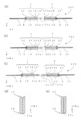
- the disclosed optical module 10 includes a first ferrule 1, a second ferrule 2, and a polarization-independent optical isolator 3.
- the first ferrule 1 has, for example, a cylindrical shape or a square tubular shape.
- the first ferrule 1 has, for example, a diameter of ⁇ 0.3 mm to ⁇ 2.5 mm and a length of 2.0 mm to 10 mm.
- reference numerals 11 and 12 indicate optical fibers.
- the first ferrule 1 has a first end portion 12, a second end portion 13, and a first through hole 10 penetrating the first end portion 12 and the second end portion 13. .
- the path direction of the light is the X-axis direction in FIG. 2, and the light from an external light source such as an LD is incident on the opening located at the first end portion 12 and passes through the first through hole 10. Then, it is emitted from the opening located at the second end portion 13.
- Light from an external light source such as an LD may be directly incident on the first through hole 10 or may be incident on the first through hole 10 via the optical fiber 11.
- the first collimator lens 14 outputs a substantially parallel luminous flux.
- Examples of the material constituting the first ferrule 1 include zirconia ceramics, alumina ceramics, and glass.
- zirconia ceramics are ceramics containing zirconia (ZrO 2 ) as a main component, and the main component is a component containing 80% by mass or more of 100% by mass of all the components constituting the ceramics. is there.
- alumina ceramics The same applies to alumina ceramics.
- the material of the first ferrule 1 is zirconia ceramics, it has high mechanical strength and excellent wear resistance, so that it can be used for a long period of time.
- the material of the first ferrule 1 is glass, it is possible to visually confirm whether or not the first collimator lens 14 or the like located in the first through hole 10 is correctly positioned.
- the first through hole 10 may be concentric with respect to the outer shape and extend linearly when the first ferrule 1 has a cylindrical shape.
- the optical axis can be adjusted without considering the position of the through hole with respect to the outer shape and the extending direction of the through hole. Therefore, the optical axis of the light passing through the first through hole 10 can be adjusted. It's easy.
- an optical fiber 11 When an optical fiber 11 is used when an external light source is incident into the first through hole 10, an optical fiber having an outer diameter of 125 ⁇ m specified by JIS standard or TIA / EIA standard may be used.
- the size of the diameter of the first through hole 10 can be appropriately determined with respect to the numerical value specified in this standard.
- the diameter of the first through hole 10 is, for example, ⁇ 0.08 mm to ⁇ 0.128 mm, and is determined by the diameter of the fiber used.
- Examples of the optical fiber 11 include a quartz optical fiber, a plastic optical fiber, and a multi-component glass optical fiber.
- the optical fiber 11 is inserted into the first through hole 10 from the first end 12 side of the first ferrule 1, and is fixed to the first ferrule 1 by filling the first through hole 10 with the adhesive 8. ..
- an acrylic resin, an epoxy resin, a vinyl resin, an ethylene resin, a silicone resin, a urethane resin, a polyamide resin, a fluorine resin, a polyptazien resin, a polycarbonate resin, or the like is used. Can be done. Further, among the above-mentioned materials, the acrylic resin and the epoxy resin are excellent in moisture resistance, heat resistance, peeling resistance and impact resistance.
- the first end portion 12 of the first ferrule 1 has a tapered shape in which the opening side is wider than the inside of the first ferrule 1 in a cross-sectional view in the X-axis direction. You may. Further, as shown in FIG. 2E, the edge of the opening on the first end 12 side may have a shape with rounded corners. When satisfying such a configuration, the first collimator lens 14 and the optical fiber 11 can be easily inserted into the first through hole 10. Further, it is easy to insert the adhesive 8 for fixing the optical fiber 11. The first collimator lens 14 is inserted into the first through hole 10 after being connected to the optical fiber 11 in advance. Therefore, the inside of the first through hole 10 is located in the order of the optical fiber 11 and the first collimator lens 14 in the light path direction. At this time, the first collimator lens 14 may be located at the opening of the second end portion 13.
- the first surface 13a at the second end 13 of the first ferrule 1 may be, for example, a flat surface as shown in FIG. 2A.
- the first surface 13a is a surface located near the second ferrule 2.
- the first surface 13a may be a plane inclined with respect to the traveling direction of light.
- the plane inclined with respect to the traveling direction of light is, for example, 2 in the cross-sectional view in the X-axis direction with reference to the Z-axis direction, which is the direction perpendicular to the X-axis direction, as shown in FIG. It is a plane inclined in the range of ° to 12 °.
- the optical axis of the reflected light on the first surface 13a is inclined, so that the reflected light on the first surface 13a is the third core of the first optical fiber 11. It is rarely combined with 11a to become return light.
- the first transparent member 15 may be connected to the first collimator lens 14. At this time, in the X-axis direction, the first collimator lens 14 and the first transparent member 15 are located in the first through hole 10 in this order, and the first transparent member 15 is located in the opening of the second end portion 13. May be good.
- the first transparent member 15 is located at the opening of the second end portion 13, when the second end portion 13 is polished to form the first surface 13a, the powder generated by the polishing is the first through hole. Since it is difficult to enter 10 and the absorbed or reflected light is less, the loss of light amount is less likely to occur.
- the first collimator lens 14 and the first transparent member 15 may be connected by an adhesive 8 or may be fused by heat treatment.
- the material of the first transparent member 15 may be glass.
- an acrylic resin or an epoxy resin is used as the adhesive 8
- the refractive index between the glass and the acrylic resin or the epoxy resin is satisfied. Since the values of are close to each other, reflected light is less likely to be generated between the glass and the adhesive 8.
- the first collimator lens 14 is a lens having a property of obtaining a substantially parallel luminous flux, and when it is located in the first through hole 10, for example, a graded index type (GI) multimode optical fiber is used as the first collimator lens. It can be used as 14.
- the GI multimode optical fiber has a continuously changing refractive index, and outputs substantially parallel light from the distribution of the refractive index, so that it functions as a collimator lens. Therefore, if the GI multimode optical fiber is used, the optical module 100 can be downsized as compared with the case where the collimator lens is arranged.
- the reflected light is reflected because the GI multimode optical fiber and the glass have similar refractive index values. Is unlikely to occur, and return light is less likely to occur.
- the second ferrule 2 has a third end portion 22, a fourth end portion 23, and a second through hole 20 penetrating the third end portion 22 and the fourth end portion 23. ..
- the light enters through the opening located at the third end 22, passes through the second through hole, and is emitted from the opening located at the fourth end 23.
- FIGS. 2A to 2C an example in which the second collimator lens 24 is provided near the third end portion 22 in the second through hole 20 is shown.
- the second ferrule 2 has the second collimator lens 24.
- the edge of the opening on the side of the fourth end portion 23 may have a shape with rounded corners.
- the second collimator lens 24 and the optical fiber 21 can be easily inserted into the second through hole 20. Further, it is easy to insert the adhesive 8 for fixing the optical fiber 21.
- the second collimator lens 24 is inserted after being connected to the optical fiber 21 in advance. Therefore, the inside of the second through hole 20 is located in the order of the second collimator lens 24 and the optical fiber 21 in the traveling direction of light. At this time, the second collimator lens 24 may be located at the opening of the third end portion 22.
- the second surface 22a at the third end 22 of the second ferrule 2 may be, for example, a flat surface as shown in FIG. 2A.
- the second surface 22a is a surface located near the first ferrule 1. When it is a flat surface, it is easy to install the polarization-independent optical isolator 4.
- the second surface 22a may be a plane inclined with respect to the traveling direction of light.
- the plane inclined with respect to the traveling direction of light is, for example, 2 in the cross-sectional view in the X-axis direction with reference to the Z-axis direction, which is the direction perpendicular to the X-axis direction, as shown in FIG. It is a plane inclined in the range of ° to 12 °.
- the optical axis of the reflected light on the second surface 22a is inclined, so that the reflected light on the second surface 22a is coupled to the first optical fiber 11. It rarely becomes a return light.
- a second transparent member 25 may be connected to the second collimator lens 24.
- the second transparent member 25 and the second collimator lens 24 are located in the second through hole 20 in this order, and the second transparent member 25 is located in the opening of the third end portion 22. May be good.
- the powder generated by polishing is the second through hole. Since it is difficult to enter 20 and there is little absorption or reflection of light by the powder that has entered, there is little loss of light amount.
- the second collimator lens 24 and the second transparent member 25 may be connected by the adhesive 8 or may be fused by heat treatment.
- the description of the material of the second transparent member 25, the second collimator lens 24, and the optical fiber 21 is the same as the above description regarding the first transparent member 15, the first collimator lens 14, and the optical fiber 11, and thus will be omitted.
- the first ferrule 1 and the second ferrule 2 may be independent of each other. As a result, the light emitted from the opening on the second end 13 side of the first through hole 10 in the first ferrule 1 is centered by moving the second ferrule 2 so as to enter the second through hole 20. Can be done.
- the first surface 13a in the first ferrule 1 and the second surface 22a in the second ferrule 2 may or may not be located in parallel.
- the first through hole 10 in the first ferrule 1 is concentric with respect to the outer shape and extends linearly
- the second through hole 20 in the second ferrule 2 is concentric with respect to the outer shape and linearly extends.
- the first surface 13a in the first ferrule 1 is extended.
- the optical axis can be adjusted by arranging the second surface 22a in the second ferrule 2 so as to be parallel to each other.
- a mixed powder of zirconium oxide powder and yttrium oxide powder is sufficiently mixed and pulverized by a ball mill or the like, and then a binder is added to the pulverized product and then mixed to obtain a molding material.
- the mixed powder is, for example, a mixture of 85 to 99% by mass of zirconium oxide powder and 1 to 15% by mass of yttrium oxide powder in 100% by mass of the mixed powder.
- the mixed powder may be 90 to 99% by mass of zirconium oxide powder and 1 to 10% by mass of yttrium oxide powder, 95 to 99% by mass of zirconium oxide powder, and 1 to 5% by mass of yttrium oxide powder in 100% by mass of the mixed powder. It may be% by mass.
- a molded body having a shape similar to the final shape and having through holes is formed.
- a molded product is obtained by filling the cavity of a molding die having a shape similar to the final shape with a molding material and performing press molding at a predetermined pressure.
- the method for obtaining the molded product is not limited to the above-mentioned press molding, and a method such as injection molding, casting molding, cold hydrostatic molding, or extrusion molding may be adopted.
- a sintered body is obtained by firing the obtained molded body. Specifically, after degreasing by putting the obtained molded product into a degreasing furnace at 500 to 600 ° C. for 2 to 10 hours, the degreased molded product is placed at 1300 to 1500 ° C. in an oxygen atmosphere. A sintered body is obtained by firing for 0.5 to 3 hours.
- the outer peripheral surface of the obtained sintered body and the inner peripheral surface of the through hole are polished to form the first end portion 12, the second end portion 13, and the first through hole 10. Specifically, it is processed by pressing a grindstone in a state where the sintered body is rotated. At this time, if grinding oil is used, polishing can be performed while suppressing an increase in the roughness of the polished surface. As described above, the first ferrule 1 can be manufactured.
- the polarization-independent optical isolator 4 has a prismatic shape, for example.
- the end face may be an inclined flat surface.
- the first through hole 10 in the first ferrule 1 is concentric with respect to the outer shape and extends linearly.
- the first surface 13a of the two end portions 13 is an inclined plane, and the end surface of the polarization-independent optical isolator 4 is inclined so as to be parallel to the first surface 13a. This facilitates the installation of the polarization-independent optical isolator 4 on the first surface 13a.
- the polarization-independent optical isolator 4 has, for example, a size in which the size of the installation surface falls within the range of 0.2 mm to 1.5 mm in length and 0.2 mm to 1.5 mm in width, and has a length in the optical axis direction.
- the size is within the range of 1.0 mm to 2.5 mm.
- the polarization-independent optical isolator 4 includes a first birefringent crystal 41, a Faraday rotator 42, a 1/2 wave plate 43, and a second birefringent crystal 44. Is glued together. At this time, the Faraday rotator 42 and the 1/2 wave plate 43 are sandwiched between the first birefringence crystal 41 and the second birefringence crystal 44, respectively. As for the order of 43, whichever is located first with respect to the path direction of the light. Further, the antireflection material may be located between the first birefringence crystal 41, the Faraday rotator 42, the 1/2 wave plate 43, and the second birefringence crystal 44, respectively. Thereby, the reflected light on the surface (interface) of the boundary between the members can be reduced. The antireflection material is provided at the interface, but is not indicated by a reference numeral in the drawing because the drawing becomes complicated.
- the polarization-independent optical isolator 4 is located on the path of light emitted from the opening on the second end 13 side of the first through hole 10, and is located at the second end 13 of the first ferrule 1 or the second ferrule 2. It is located at the third end 22 of the.
- the polarization-independent optical isolator 4 may be adhered to the second end portion 13 or the third end portion 22 by the adhesive 8. At this time, when the refractive index difference between the adhesive 8 and the polarization-independent optical isolator 4 and the collimator lens and the optical fiber at the opening on the side where the polarization-independent optical isolator 4 is located is close, There is little reflected light at the interface.
- the material may be provided. When such a configuration is satisfied, there is little light reflection.
- the antireflection material for example, titanium dioxide (TiO 2 ), silicon dioxide (SiO 2 ), tantalum pentoxide (Ta 2 O 5 ) or the like can be used.
- the Faraday rotator 42 used in the polarization-independent optical isolator 4 is, for example, a Bi-substituted garnet to which Tb, Gd, and Ho are added, yttrium / iron / garnet (YIG), or a self that does not require a magnet 45 described later. Bias type can be mentioned.
- Examples of the first birefringence crystal 41 and the second birefringence crystal 44 of the polarization-independent optical isolator 4 include rutile, ittrium vanadate (YVO 4 ), calcite (CaCO 3 ), ⁇ -BBO crystal and the like. Be done. Further, examples of the 1/2 wavelength plate 43 include quartz, sapphire and the like. Although the materials have been illustrated so far, the materials are not limited to these, and any material having the same function can be used.
- the polarization-independent optical isolator 4 has a first polarization-independent optical isolator 4a at the second end 13 and a second polarization-independent optical isolator 4 at the third end 2.
- the type optical isolator 4b may be located. At this time, the first polarization-independent optical isolator 4a and the second polarization-independent optical isolator 4b do not have to be in contact with each other.
- the optical fiber is in the direction opposite to the light path direction in which the reflected light travels.
- the distance between the third core 11a of 11 and the light separated into normal light and abnormal light becomes long, and the isolation effect is excellent, so that the optical characteristics are excellent.
- the second polarization-independent optical isolator 4b is preferably arranged with the light separation direction rotated by 90 ° with respect to the first polarization-independent optical isolator 4a.
- ⁇ Manufacturing method of polarization-independent optical isolator> An example of a method for manufacturing the polarization-independent optical isolator 4 will be described below. First, optical adjustment is performed using a large-sized 1/2 wave plate and a birefringent crystal. After that, the substrates can be manufactured by adhering the substrates with an adhesive 8 and performing cutting. As a result, a large number of polarization-independent optical isolators can be easily manufactured.
- a polarization-independent optical isolator with an inclined end face can be manufactured, and the polarization-independent optical isolator is tilted according to the shape of the end face of the ferrule.
- the magnet 45 is located on the outer periphery of the polarization-independent optical isolator 4 along the light path direction in the first through hole 10. You may be.
- the magnet 45 when the magnet 45 is positioned, when the Faraday rotator 42 is not a self-biased type but is composed of a Bi-substituted garnet or YIG, linearly polarized light is transmitted to the substance in the traveling direction parallel to the magnetic field. It can exhibit the Faraday effect that the plane of polarization rotates when it is made to flow. In this way, the magnet 45 applies a magnetic field to the polarization-independent optical isolator 4.
- the magnet 45 may be any as long as it applies a magnetic field to the polarization-independent optical isolator 4, and may be adhered to the second end portion 13 or the third end portion 22 by using an adhesive 8. Further, an adhesive is applied to the inner circumference and end of the first holder 61 that holds the first ferrule 1, which will be described later, the inner circumference and end of the second holder 62 that holds the second ferrule 2, and the inner circumference of the third sleeve 65. It may be adhered using 8.
- the shape of the magnet 45 may be rod-shaped as well as tubular, but when it is tubular, a magnetic field can be applied to the polarization-independent optical isolator 4 from the circumferential direction.
- the magnet 45 is preferably samarium-cobalt (SmCo) -based. If it is an SmCo type, the Curie temperature is high and the heat resistance is high, so that the magnetism of the magnet 45 does not easily decrease even if heat treatment is performed.
- SmCo samarium-cobalt
- the optical module 100 includes a first sleeve 5 having a third through hole 50, and in the third through hole 50, a second end portion 13 of the first ferrule 1 and a second end portion 13
- the polarization-independent optical isolator 4 and the third end 22 of the second ferrule 2 may be located.
- the first through hole 10 in the first ferrule 1 is concentric with respect to the outer shape and extends linearly
- the second through hole 20 in the second ferrule 2 is concentric with respect to the outer shape and linearly extends.
- the outer circumference of the first ferrule 1 is connected to one end of the third through hole 50
- the outer circumference of the second ferrule 2 is connected from the opposite end of the third through hole 50.
- the optical axis can be aligned.
- the adhesive 8 may be used to fit the first ferrule 1 and the second ferrule 2 into the third through hole 50. Further, the adhesive 8 may be used after fitting the first ferrule 1 and the second ferrule 2 into the third through hole 50. Thereby, the connection strength between the third through hole 50 and the first ferrule 1 and the second ferrule 2 can be improved.
- a magnet may be adhered to the outer periphery of the first sleeve 5 by using an adhesive 8, or the first sleeve 5 may be attached.
- the magnet may be adhered to the inner circumference using the adhesive 8.
- Zirconia ceramics or the like is used as the material of the first sleeve 5.
- the material of the first sleeve 5 is zirconia ceramics, it has high mechanical strength and excellent wear resistance, so that it can be used for a long period of time.
- the resin material 51 is located in the third through hole 50 of the first sleeve 5, and in the space between the second end portion 13 and the third end portion 22.
- the resin material 51 include acrylic resin, epoxy resin, vinyl resin, ethylene resin, silicone resin, urethane resin, polyamide resin, fluorine resin, polyptadien resin, polycarbonate resin and the like. .. Further, among the above-mentioned materials, the acrylic resin and the epoxy resin are excellent in moisture resistance, heat resistance, peeling resistance and impact resistance.
- the resin material 51 is located in the region inside the first sleeve 5, for example, since the refractive index is close to that of the second transparent member 25 existing in the traveling direction of light, an antireflection material is provided on the second transparent member 25. Reflection at the interface can be suppressed even if it is not provided.
- the first collimator lens 14 is the first optical fiber 140 having the first core 14a and the first clad 14b
- the second collimator lens 24 is the second core 24a.
- the second optical fiber 240 having the second clad 24b may be used.
- the first optical fiber 140 and the second optical fiber 240 are GI multimode optical fibers.
- the first ferrule 1 further includes an optical fiber 11 (hereinafter, referred to as a third optical fiber in the description of FIG. 4) having a third core 11a located in the first through hole 10. ing.
- the third optical fiber 11 is located in the order of the third optical fiber 11 and the first optical fiber 140 with respect to the light path direction in the first through hole 10.
- the second ferrule 2 further has an optical fiber 21 (hereinafter, referred to as a fourth optical fiber in the description with respect to FIG. 4) having a fourth core 21a located in the second through hole 20. Further, the fourth optical fiber 21 is located in the order of the second optical fiber 240 and the fourth optical fiber 21 with respect to the light path direction in the second through hole 20.
- the core diameter of the third core 11a is smaller than the core diameter of the fourth core 21a ((b) in FIG. 4). Further, at this time, the difference in the refractive index between the first core 14a and the first clad 14b may be larger than the difference in the refractive index between the second core 24a and the second clad 24b.
- the core diameter of the fourth core 21a is smaller than the core diameter of the third core 11a ((a) in FIG. 4). Further, at this time, the difference in the refractive index between the first core 14a and the first clad 14b may be smaller than the difference in the refractive index between the second core 24a and the second clad 24b.
- MFDs mode field diameters
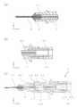
- FIG. 5 is a perspective view of the receptacle with an isolator according to the fourth embodiment.
- FIG. 6 is a cross-sectional view of the receptacle with an isolator according to the fourth embodiment.
- (a) and (b) in FIG. 6 are partial cross-sectional views.
- the isolator-equipped receptacle 6 according to the fourth embodiment includes an optical module 100 and a receptacle 60.
- the receptacle 6 includes a second sleeve 63 having a cylindrical shape and a sleeve case 64 that holds the outer circumference of the second sleeve 63.
- the second sleeve 63 has, for example, a cylindrical shape and is made of zirconia ceramics.
- the sleeve case 64 has a cylindrical shape, for example, and is made of a metal such as stainless steel or a polybutylene terephthalate (PBT) resin.
- the second ferrule 2 When connecting the receptacle 60 and the optical module 100, first, the second ferrule 2 is connected by inserting it into the through hole of the second sleeve 63 from the fourth end 23 side. At this time, if the shape of the fourth end portion 23 is a convex surface, the interference between the end portion of the external optical plug and the fourth end portion 23 is reduced as compared with the case of a shape other than the convex surface, and the physical shape is reduced. As a result, the reliability of the connection between the receptacle 6 with an isolator and the external optical plug is improved. Further, the outer circumference of the second sleeve 63 is connected in contact with the inner circumference of the sleeve case 64.
- the first ferrule 1 is inserted into the through hole of the first holder 61, and is connected to the first holder 61 by contacting the outer circumference of the first ferrule 1 with the inner circumference of the first holder 61.
- the outer circumferences of the second ferrule 2 and the sleeve case 64 are connected in contact with the inner circumference of the second holder 62.
- the receptacle 6 with an isolator is formed.
- it may be bonded by the adhesive 8 or it may be welded by YAG (yttrium aluminum garnet).
- the through holes in the first holder 61 and the second holder 62 are preferably cylindrical from the viewpoint of ease of processing. Further, if the through hole in the first holder 61 has a cylindrical shape and the first ferrule 1 also has a cylindrical shape, the connection strength between the first holder 61 and the first ferrule 1 is increased. Further, by firmly fitting and connecting, the deviation of the optical axis due to the loose connection between the first holder 61 and the first ferrule 1 can be reduced, and the optical reliability of the receptacle 6 with an isolator is enhanced. The same applies to the second holder 62 and the second ferrule 2.
- the first holder 61 and the second holder 62 are made of stainless steel, a metal such as stainless steel, or a resin such as PBT. If stainless steel is used, the first holder 61 and the second holder 62 are deformed by stress received from the outside. Since it is difficult to use, it can be used for a long period of time.
- the third sleeve 65 may be positioned so as to hold the outer circumference of the first holder 61. Further, with respect to the second holder 62, the second ferrule 2 is provided so that the light emitted from the opening on the second end 13 side of the first through hole 10 is incident on the second through hole 20 of the second ferrule 2. May be connected to the end of the second holder 62 by the adhesive 8 after the centering is adjusted. Good light is obtained by moving the second ferrule 2 so that the light emitted from the opening on the second end 13 side of the first through hole 10 is incident on the second through hole 20 and performing optical alignment. It is possible to form a receptacle 6 with an isolator having characteristics.
- the third sleeve 65 is made of stainless steel, a metal such as stainless steel, or a resin such as PBT. If stainless steel is used, the third sleeve 65 is not easily deformed by external stress, so that the third sleeve 65 is not easily deformed over a long period of time. Can be used.
- FIG. 7 is a perspective view of the optical unit according to the fifth embodiment of the present invention.
- the optical unit 7 according to the embodiment of the present invention includes the above-mentioned receptacle 6 with an isolator and an external substrate 70.
- the external substrate 70 in FIG. 7 is made of silicon photonics, and is connected to the receptacle 6 with an isolator by an adhesive 8. At this time, the LD is arranged on the external substrate 70, but the receptacle 6 with an isolator is provided with the optical fiber 11, and the LD is transmitted to the external substrate 70 by being incident on the first through hole 10 through the light of the LD. It can be arranged freely.
- optical module 100 the receptacle 6 with an isolator, and the optical unit 7 provided with the optical module 100 of each embodiment have been described above, the present invention is not limited to the above-described embodiment. That is, various changes and combinations of embodiments may be made without departing from the gist of the present invention.
- Optical module 1 First ferrule 10: First through hole 11: Optical fiber (third optical fiber) 11a: 3rd core 12: 1st end 13: 2nd end 14: 1st collimator lens 14a: 1st core 14b: 1st clad 140; 1st optical fiber 15: 1st transparent member 2: 2nd ferrule 20: Second through hole 21: Optical fiber (fourth optical fiber) 21a: 4th core 22: 3rd end 23: 4th end 24: 2nd collimeter lens 24a: 2nd core 24b: 2nd clad 240: 2nd optical fiber 25: 2nd transparent member 4: no polarization Dependent optical isolator 4a: First polarization-independent optical isolator 4b: Second polarization-independent optical isolator 41: First birefringent crystal 42: Faraday rotator 43: 1/2 wave plate 44: Second duplex Birefringent crystal 45: Magnet 5: First sleeve 50: Third through hole 51:
Landscapes
- Physics & Mathematics (AREA)
- General Physics & Mathematics (AREA)
- Optics & Photonics (AREA)
- Optical Couplings Of Light Guides (AREA)
Priority Applications (3)
| Application Number | Priority Date | Filing Date | Title |
|---|---|---|---|
| US17/613,515 US20220252794A1 (en) | 2019-05-29 | 2020-05-28 | Optical module, receptacle equipped with isolator, and optical unit |
| JP2021522874A JPWO2020241774A1 (https=) | 2019-05-29 | 2020-05-28 | |
| CN202080037910.0A CN113939752A (zh) | 2019-05-29 | 2020-05-28 | 光模块、带隔离器插座以及光组件 |
Applications Claiming Priority (2)
| Application Number | Priority Date | Filing Date | Title |
|---|---|---|---|
| JP2019100407 | 2019-05-29 | ||
| JP2019-100407 | 2019-05-29 |
Publications (1)
| Publication Number | Publication Date |
|---|---|
| WO2020241774A1 true WO2020241774A1 (ja) | 2020-12-03 |
Family
ID=73553769
Family Applications (1)
| Application Number | Title | Priority Date | Filing Date |
|---|---|---|---|
| PCT/JP2020/021180 Ceased WO2020241774A1 (ja) | 2019-05-29 | 2020-05-28 | 光モジュール、アイソレータ付きレセプタクルおよび光ユニット |
Country Status (4)
| Country | Link |
|---|---|
| US (1) | US20220252794A1 (https=) |
| JP (1) | JPWO2020241774A1 (https=) |
| CN (1) | CN113939752A (https=) |
| WO (1) | WO2020241774A1 (https=) |
Citations (6)
| Publication number | Priority date | Publication date | Assignee | Title |
|---|---|---|---|---|
| JPH08194130A (ja) * | 1995-01-13 | 1996-07-30 | Kyocera Corp | 光コネクタ |
| JPH08286150A (ja) * | 1995-04-17 | 1996-11-01 | Sumitomo Electric Ind Ltd | 光アイソレータ |
| US20020186915A1 (en) * | 2001-06-08 | 2002-12-12 | Tai-Cheng Yu | Optical isolator |
| JP2003043294A (ja) * | 2001-05-19 | 2003-02-13 | Lucent Technol Inc | モード変換装置 |
| JP2007010826A (ja) * | 2005-06-29 | 2007-01-18 | Kyocera Corp | 光コネクタ |
| JP2008276204A (ja) * | 2007-03-30 | 2008-11-13 | Kyocera Corp | 光デバイス及びそれを用いた光レセプタクル |
Family Cites Families (7)
| Publication number | Priority date | Publication date | Assignee | Title |
|---|---|---|---|---|
| US5293438A (en) * | 1991-09-21 | 1994-03-08 | Namiki Precision Jewel Co., Ltd. | Microlensed optical terminals and optical system equipped therewith, and methods for their manufacture, especially an optical coupling method and optical coupler for use therewith |
| US5446813A (en) * | 1994-08-08 | 1995-08-29 | Industrial Technology Research Institute | Optical isolator |
| FR2797058A1 (fr) * | 1999-07-29 | 2001-02-02 | Kyocera Corp | Dispositif du type a troncon de fibre et module optique l'utilisant et procede de fabrication d'un dispositif du type a troncon de fibre |
| FR2842915B1 (fr) * | 2002-07-26 | 2004-10-08 | Atmel Grenoble Sa | Procede et dispositif de positionnement d'un composant optique entre deux fibres optiques |
| US7150566B2 (en) * | 2003-12-22 | 2006-12-19 | Kyocera Corporation | Optical device |
| JP2006047951A (ja) * | 2004-06-29 | 2006-02-16 | Kyocera Corp | 光アイソレータ |
| JP4883969B2 (ja) * | 2004-09-27 | 2012-02-22 | 京セラ株式会社 | 光レセプタクルおよびこれを用いた光モジュール |
-
2020
- 2020-05-28 CN CN202080037910.0A patent/CN113939752A/zh active Pending
- 2020-05-28 WO PCT/JP2020/021180 patent/WO2020241774A1/ja not_active Ceased
- 2020-05-28 US US17/613,515 patent/US20220252794A1/en not_active Abandoned
- 2020-05-28 JP JP2021522874A patent/JPWO2020241774A1/ja active Pending
Patent Citations (6)
| Publication number | Priority date | Publication date | Assignee | Title |
|---|---|---|---|---|
| JPH08194130A (ja) * | 1995-01-13 | 1996-07-30 | Kyocera Corp | 光コネクタ |
| JPH08286150A (ja) * | 1995-04-17 | 1996-11-01 | Sumitomo Electric Ind Ltd | 光アイソレータ |
| JP2003043294A (ja) * | 2001-05-19 | 2003-02-13 | Lucent Technol Inc | モード変換装置 |
| US20020186915A1 (en) * | 2001-06-08 | 2002-12-12 | Tai-Cheng Yu | Optical isolator |
| JP2007010826A (ja) * | 2005-06-29 | 2007-01-18 | Kyocera Corp | 光コネクタ |
| JP2008276204A (ja) * | 2007-03-30 | 2008-11-13 | Kyocera Corp | 光デバイス及びそれを用いた光レセプタクル |
Also Published As
| Publication number | Publication date |
|---|---|
| CN113939752A (zh) | 2022-01-14 |
| JPWO2020241774A1 (https=) | 2020-12-03 |
| US20220252794A1 (en) | 2022-08-11 |
Similar Documents
| Publication | Publication Date | Title |
|---|---|---|
| US10191224B2 (en) | Optical receptacle | |
| CN101322059B (zh) | 带有光隔离器的插座及其制造方法 | |
| JP4446596B2 (ja) | 光モジュールの製造方法 | |
| WO2020241774A1 (ja) | 光モジュール、アイソレータ付きレセプタクルおよび光ユニット | |
| US20210026080A1 (en) | Optical receptacle and optical transceiver | |
| JP4883969B2 (ja) | 光レセプタクルおよびこれを用いた光モジュール | |
| US20050169584A1 (en) | Optical device | |
| JP5414568B2 (ja) | 光学素子付光部品及びそれを用いた光学素子付光レセプタクル | |
| JP4658844B2 (ja) | レセプタクルおよび該レセプタクルを備える光モジュール | |
| JP4883927B2 (ja) | レンズ付き光レセプタクルとこれを用いた光モジュール | |
| WO2021039572A1 (ja) | 光モジュールおよび光ユニット | |
| JP4150310B2 (ja) | 光アイソレータ付きレセプタクル | |
| CN219392316U (zh) | 一种具有隔离器功能的准直器组件 | |
| JP2004325606A (ja) | 光アイソレータ付きレセプタクル | |
| JP7071219B2 (ja) | アイソレータ付レセプタクルおよび光学装置 | |
| JP4812342B2 (ja) | 光コネクタ | |
| JP2009205151A (ja) | 光デバイス | |
| JP2007226182A (ja) | 光アイソレータ付き光ファイバ保持部品およびそれを用いた光レセプタクルならびに光モジュール | |
| JPH0949989A (ja) | 多心光アイソレータ | |
| JP2011048268A (ja) | ファイバスタブ型光デバイス | |
| JP2001215447A (ja) | ファイバスタブ型光デバイス及びそれを用いた光モジュール | |
| JP2005215156A (ja) | 光デバイス | |
| JP2004205861A (ja) | 光アイソレータ付き多芯光ファイバ部品およびそれを用いた双方向モジュール | |
| JP2006126477A (ja) | 光アイソレータ付き光ファイバ保持具の製造方法 | |
| JP2011070148A (ja) | ホルダ付きファイバスタブ、ファイバスタブ付き光アイソレータ、光アイソレータ付き光レセプタクル、および光モジュール |
Legal Events
| Date | Code | Title | Description |
|---|---|---|---|
| 121 | Ep: the epo has been informed by wipo that ep was designated in this application |
Ref document number: 20814393 Country of ref document: EP Kind code of ref document: A1 |
|
| ENP | Entry into the national phase |
Ref document number: 2021522874 Country of ref document: JP Kind code of ref document: A |
|
| NENP | Non-entry into the national phase |
Ref country code: DE |
|
| 122 | Ep: pct application non-entry in european phase |
Ref document number: 20814393 Country of ref document: EP Kind code of ref document: A1 |