WO2020241579A1 - 鋼矢板の圧延機のガイド及び鋼矢板の製造方法 - Google Patents
鋼矢板の圧延機のガイド及び鋼矢板の製造方法 Download PDFInfo
- Publication number
- WO2020241579A1 WO2020241579A1 PCT/JP2020/020571 JP2020020571W WO2020241579A1 WO 2020241579 A1 WO2020241579 A1 WO 2020241579A1 JP 2020020571 W JP2020020571 W JP 2020020571W WO 2020241579 A1 WO2020241579 A1 WO 2020241579A1
- Authority
- WO
- WIPO (PCT)
- Prior art keywords
- steel sheet
- guide
- sheet pile
- rolling
- pair
- Prior art date
- Legal status (The legal status is an assumption and is not a legal conclusion. Google has not performed a legal analysis and makes no representation as to the accuracy of the status listed.)
- Ceased
Links
Images



Classifications
-
- B—PERFORMING OPERATIONS; TRANSPORTING
- B21—MECHANICAL METAL-WORKING WITHOUT ESSENTIALLY REMOVING MATERIAL; PUNCHING METAL
- B21B—ROLLING OF METAL
- B21B1/00—Metal-rolling methods or mills for making semi-finished products of solid or profiled cross-section; Sequence of operations in milling trains; Layout of rolling-mill plant, e.g. grouping of stands; Succession of passes or of sectional pass alternations
- B21B1/08—Metal-rolling methods or mills for making semi-finished products of solid or profiled cross-section; Sequence of operations in milling trains; Layout of rolling-mill plant, e.g. grouping of stands; Succession of passes or of sectional pass alternations for rolling structural sections, i.e. work of special cross-section, e.g. angle steel
- B21B1/082—Piling sections having lateral edges specially adapted for interlocking with each other in order to build a wall
-
- B—PERFORMING OPERATIONS; TRANSPORTING
- B21—MECHANICAL METAL-WORKING WITHOUT ESSENTIALLY REMOVING MATERIAL; PUNCHING METAL
- B21B—ROLLING OF METAL
- B21B39/00—Arrangements for moving, supporting, or positioning work, or controlling its movement, combined with or arranged in, or specially adapted for use in connection with, metal-rolling mills
- B21B39/14—Guiding, positioning or aligning work
Definitions
- the present invention relates to a guide for a rolling mill for steel sheet piles and a method for manufacturing steel sheet piles.
- Steel sheet piles such as hat-shaped steel sheet piles are used as earth retaining members for civil engineering work, for example.
- the hat-shaped steel sheet pile has features such as an effective width of 900 mm, a left-right asymmetric joint shape, and a fitting portion at the outermost edge of the wall body.
- 600 width steel sheet pile there are advantages such as shortening of construction period and improvement of rigidity as a wall body, and from 600 width steel sheet pile to hat shaped steel. The replacement of varieties with sheet piles is progressing.
- Patent Document 1 the web is sandwiched between the first guide that contacts the web and the flange and the first guide on each of the entry side and the exit side of the rolling mill.
- a method of stabilizing the biting posture and the way of exiting by arranging the guide 2 and the third guide that restrains the arm portion from above and below is disclosed.
- the present invention has been made by paying attention to the above-mentioned problems, and it is possible to suppress the occurrence of guide clogging and guide flaws, and the guide of the steel sheet pile rolling mill and the steel sheet pile, which are excellent in maintainability, It is intended to provide a manufacturing method.
- a web extending in one direction and a web connected to both ends of the web in the one direction and extending at an angle with respect to the one direction.
- a guide for a rolling mill for steel sheet piles which is provided on the entrance side of a rolling mill having an upper roll and a lower roll in which a hole shape corresponding to the shape of the steel sheet pile is engraved.
- a flat portion corresponding to the flat portion in the material having a web guide that restrains the corresponding web-corresponding portion from one direction in the vertical direction and guides the corresponding portion to the hole shape, and one or more rollers that can rotate in the rolling direction.
- a guide for a rolling mill for steel sheet piles is provided, which comprises a pair of roller guides that restrain the corresponding portion from another direction in the vertical direction and guide the corresponding portion to the hole shape.
- a web extending in one direction and a pair of flanges connected to both sides of the web and extending at an angle with respect to the one direction.
- a method for manufacturing a steel sheet pile in which a guide of the above-mentioned steel sheet pile rolling mill is provided on the entrance side of a rolling mill having a hole shape, and a rolling step of rolling with the above-mentioned rolling mill is provided.
- a guide for a steel sheet pile rolling mill and a method for manufacturing a steel sheet pile which can suppress the occurrence of guide clogging and guide flaws and are excellent in maintainability.
- FIG. 6 is a cross-sectional view taken along the line AA'of FIG. It is a schematic diagram which shows the cross-sectional shape of the U-shaped steel sheet pile.
- the rolling equipment 2 is an equipment for manufacturing a steel sheet pile 1 by rolling a rectangular slab or the like, which is a material, with a plurality of rolling mills.
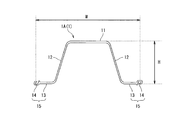
- the manufactured steel sheet pile 1 is a hat-shaped steel sheet pile 1A having a hat-shaped uniform cross-sectional shape orthogonal to the longitudinal direction, as shown in FIG.
- the hat-shaped steel sheet pile 1A has a web 11, a pair of flanges 12, a pair of arm portions 13, and a pair of joint portions 14 as a cross-sectional shape.
- the web 11 is a portion extending in one direction (the left-right direction in FIG.
- the pair of flanges 12 are portions connected to both ends of the web 11 in the left-right direction and extend at an angle with respect to the left-right direction. In the example shown in FIG. 1, the pair of flanges 12 are tilted and extended so that the opposite ends of the web 11 are on the lower side in the vertical direction (the vertical direction in FIG. 1 and the direction orthogonal to the horizontal direction). Exists.
- the pair of arms 13 is a portion connected to the side of the pair of flanges 12 to which the web 11 is not connected and extends in the left-right direction.
- the pair of joint portions 14 is a portion connected to the side where the flanges 12 of the pair of arm portions 13 are not connected, and have a hook-like shape that opens upward or downward in the vertical direction.
- the pair of joint portions 14 are portions used for connecting to another steel sheet pile by fitting into the joint portion of another steel sheet pile.
- the arm portion 13 and the joint portion 14 are collectively referred to as a flat portion 15.
- the flat portion 15 is a portion of the steel sheet pile 1 that is formed by connecting to the end of the flange 12 on the side where the web 11 is not connected and has a flat portion extending in the left-right direction.
- the arm portion 13 is a flat portion in the flat portion 15.
- the distance between the pair of joint portions 14 shown by W in FIG. 1 is referred to as an effective width
- the distance in the vertical direction from the flange 12 shown by H in FIG. 1 to the arm portion 13 is referred to as an effective height.
- the rectangular slab which is a material heated to a predetermined temperature in the heating furnace 3, is subjected to a rough rolling mill (BD) 4, an intermediate rolling mill (SR) 5, and a finishing rolling mill.
- a hat-shaped steel sheet pile 1A is manufactured by rolling in order at (SF) 6.
- the rough rolling mill 4 rough-shapes a rectangular slab heated in a heating furnace 3 into a rough-shaped steel piece having a substantially hat-shaped cross section orthogonal to the longitudinal direction.
- the rough rolling mill 4 has one roll set including an upper roll and a lower roll.
- a plurality of hole types called calibers for example, Box hole type, K8 hole type, and K7 hole type are engraved in this roll set.
- the intermediate rolling mill 5 rolls the material rolled by the rough rolling mill 4, and has two roll sets in which a plurality of hole molds are engraved.
- each roll set of the intermediate rolling mill 5 is engraved with two hole molds, and a total of four hole molds (for example, K6 hole type to K3 hole type) are engraved.
- the Box hole type has a hole shape (shape of a roll gap) when viewed from the rolling direction. Is a substantially square shape, and in the K8 hole type to K3 hole type, the hole shape seen from the rolling direction is a hat shape.
- the roll gap and the shape are set so that the thickness of the material to be rolled becomes thinner and the cross-sectional shape approaches the shape of the product as the hole type is used in the latter half of rolling. To.
- the finish rolling mill 6 rolls the material rolled by the intermediate rolling mill 5, and has one roll set in which two hole molds are engraved. That is, the finishing rolling mill 6 has two hole types, and these hole types are referred to as K2 hole type and K1 hole type.
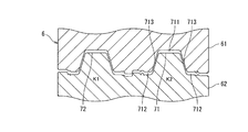
- the finish rolling mill 6 will be described in detail with reference to FIG. As shown in FIG. 3, the finishing rolling mill 6 is a set of rolls and has an upper roll 61 and a lower roll 62 arranged so as to face each other in the vertical direction which is the vertical direction.
- a K2 hole type 71 and a K1 hole type 72 according to the product shape of the hat-shaped steel sheet pile 1A are engraved on the upper roll 61 and the lower roll 62.
- the K2 hole type 71 is a hole type that rolls the cross-sectional shape of the material rolled by the intermediate rolling mill 5 into a plate thickness that is the product thickness.
- the K1 hole type 72 is a hole type in which the joint portion 14 of the material rolled by the K2 hole type 71 is bent and molded.
- the portion where the web 11 of the hat-shaped steel sheet pile 1A is rolled is designated as the first portion 711
- the portion where the arm portion 13 which is the flat portion of the flat portion 15 is rolled is designated as the second portion 712.
- the portion where 12 is rolled is referred to as a third portion 713. That is, the K2 hole type 71 has a first portion 711, a second portion 712, and a third portion 713 as the shape of the roll gap (the gap between the upper roll 61 and the lower roll 62) when viewed from the rolling direction.
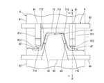
- a guide that guides the material to be rolled to the K2 hole mold 71 on the upstream side of the K2 hole mold 71 of the finish rolling mill 6 (the upstream side in the rolling direction and the entry side where the material enters the finish rolling mill 6). 8 is provided. As shown in FIGS. 4 and 5, the guide 8 includes a pair of roller guides 81, a web guide 82, an upper rest bar 83, and a lower rest bar 84.
- the pair of roller guides 81 each have a guide frame 811 and two rollers 812.
- the pair of roller guides 81 are guides that restrain the portion corresponding to the arm portion, which is a flat portion of the material to be rolled, from the upper side and guide the portion to the K2 hole type 71.
- the pair of roller guides 81 are provided on the upper side of the pair of second portions 712 when viewed from the rolling direction, that is, the first portion 711 in the direction orthogonal to the extending direction of the second portion 712. Each is provided on the side.
- the guide frame 811 is a member that supports the two rollers 812 and is fixed to the upper rest bar 83. As shown in FIG. 5, the guide frame 811 is notched diagonally so that the lower end of the end portion on the upstream side (left side in FIG. 5) in the rolling direction is located on the upper side toward the upstream side in the rolling direction. Has a shape. With such a shape, the material can be guided to the K2 hole type 71 even when the tip of the material to be rolled has a large warp.
- the two rollers 812 are fixed to the guide frame 811 in a state of being rotatable in the rolling direction of the material to be rolled, and are provided side by side in the rolling direction.
- the pair of roller guides 81 are located on the first portion 711 side (the hat-shaped web side and the upper side of FIG. 4) of the second portion 712 of the K2 hole type 71 when viewed from the rolling direction. Be distributed.
- the pair of roller guides 81 need only have the lower ends of the two rollers 812 above the roll gaps between the upper roll 61 and the lower roll 62 when viewed from the rolling direction, and further, the two rollers 812 and K2. It is preferable that a predetermined clearance d2 is provided at the second portion 712 of the hole type 71. As shown in FIG.
- the clearance d2 is the vertical distance between the lower end of the roller 812 and the upper end of the roll gap (lower end of the upper roll 61) of the second portion 712 of the K1 hole type 71 when viewed from the rolling direction. is there.
- the clearance d2 is the distance of the roll gap at the second portion 712 of the K2 hole type 71 as a predetermined distance, and the upper roll 61 and the lower roll 62 at the second portion 712 in the final rolling pass of the K2 hole type 71. It is preferable that it is about the same as the separation distance (distance of the roll gap) from.
- the final rolling pass is the rolling pass that is performed last when multiple passes are performed in the hole mold, and the rolling is performed when only one pass is performed in the hole mold. It is one pass that is rolled. That is, the distance of the roll gap in the final rolling path is the same as the plate thickness of the material to be rolled in the hole mold after rolling. Further, the clearance d2 is preferably a distance of 40% or more and 120% or less of the distance of the roll gap at the second site 712 of the K2 hole type 71, and the roll gap at the second site 712 of the K2 hole type 71. It is preferable that the distance is the same as.
- the roll gap at the second portion 712 of the K2 hole type 71 corresponds to the plate thickness of the arm portion 13 of the product of the hat-shaped steel sheet pile 1A to be rolled.
- the clearance d2 is less than 40% of the distance of the roll gap at the second portion 712 of the K2 hole type 71, the clearance d2 is too small, and there is a high possibility that the material is clogged.
- the clearance d2 is more than 120% of the distance of the roll gap at the second portion 712 of the K2 hole type 71, the material is not guided to the roll gap because the clearance d2 is too large, resulting in poor biting. It can occur.
- the web guide 82 has a shape along the first portion 711 and the third portion 713 of the K2 hole type 71, that is, a friction having a shape along the web 11 and the flange 12 of the hat-shaped steel sheet pile 1A when viewed from the rolling direction. It is a guide.
- the web guide 82 restrains the portion of the material to be rolled corresponding to the web and the flange from the lower side and guides the rolled material to the K2 hole type 71.
- the web guide 82 has a shape in which the end portion on the upstream side in the rolling direction is obliquely cut out so as to be located on the lower side as the upper end becomes the upstream side in the rolling direction. With such a shape, the material can be guided to the K2 hole type 71 even when the tip of the material to be rolled has a large downward warp.
- the web guide 82 is located below the first portion 711 and the third portion 713 of the K2 hole type 71 when viewed from the rolling direction, that is, the second portion 712 side in the direction orthogonal to the extending direction of the first portion 711. It is arranged (on the side of the hat-shaped arm and on the lower side of FIG. 4).
- the web guide 82 only needs to have its upper end below the roll clearance between the upper roll 61 and the lower roll 62 when viewed from the rolling direction, and the web guide 82 and the first portion 711 of the K2 hole type 71 and the K2 hole type 71 It is preferable that predetermined clearances d1 and d3 are provided at the third portion 713, respectively. As shown in FIG.
- the clearance d1 is in the vertical direction between the upper end of the portion of the web guide 82 corresponding to the web and the lower end of the roll gap of the first portion 711 (the upper end of the lower roll 62) when viewed from the rolling direction.
- the clearance d3 is the upper end of the portion corresponding to the flange of the web guide 82 when viewed from the rolling direction (the portion of the upper end which is inclined and extends in the left-right direction when viewed from the rolling direction) and the third portion of the K1 hole type 71. It is the distance in the perpendicular direction of the third portion 713 from the lower end of the roll gap of 713 (the upper end of the lower roll 62).
- the clearance d1 is a distance of 40% or more and 120% or less of the roll gap distance at the first portion 711 of the K2 hole type 71
- the clearance d3 is 60% or more and 180% or more of the roll gap distance at the third portion 713.
- the distance is preferably% or less.
- the roll gaps at the first portion 711 and the third portion 713 of the K2 hole type 71 correspond to the plate thicknesses of the web 11 and the flange 12 of the rolled hat-shaped steel sheet pile 1A, respectively.
- the upper rest bar 83 is a member that supports the pair of roller guides 81, and is provided so as to extend in the left-right direction.
- the upper rest bar 83 is fixedly provided to the housing or chock of the rolling mill in which the guide 8 is provided. Further, the upper rest bar 83 is provided above the K2 hole type 71 when viewed from the rolling direction, and the guide frames 811 of the pair of roller guides 81 are fixed.
- the lower rest bar 84 is a member that supports the web guide 82, and is provided so as to extend in the left-right direction.
- the lower rest bar 84 is fixedly provided to the housing or chock of the rolling mill in which the guide 8 is provided. Further, the lower rest bar 84 is provided below the K2 hole type 71 when viewed from the rolling direction, and the web guide 82 is fixed.
- the rectangular slab heated to a predetermined temperature in the heating furnace 3 is rolled in order by the rough rolling mill 4, the intermediate rolling mill 5, and the finishing rolling mill 6, thereby forming a hat having a cross-sectional shape shown in FIG.
- Manufactures steel sheet pile 1A The process of rolling with each rolling mill is also referred to as a rolling process.
- the material is rolled a plurality of times in each hole type of each rolling mill.
- the rough rolling mill 4 when the Box hole type is used as described above, the width of the rectangular slab is reduced by the Box hole type, and then the slab is bent and thinned by the K9 hole type. Are performed in order.
- the material rolled in the intermediate rolling mill 5 is rolled in the K2 hole mold 71 and then rolled in the K1 hole mold 72. At this time, the number of rolling passes in the K2 hole type 71 and the K1 hole type 72 is 1 pass.
- the material is bitten into the K2 hole type 71 through the guide 8. At this time, the material is restrained from the upper side by the pair of roller guides 81 and is restrained from the lower side by the web guide 82.
- the steel sheet pile 1 is a hat-shaped steel sheet pile 1A, but the present invention is not limited to this example.
- the steel sheet pile 1 may have another cross-sectional shape as long as it includes a web, a flange, and a flat portion which is a flat portion.
- the steel sheet pile 1 may be a U-shaped steel sheet pile 1B having a cross-sectional shape shown in FIG.
- the U-shaped steel sheet pile 1B is a steel sheet pile having a U-shaped cross section, and has a web 11, a pair of flanges 12, and a pair of joints 14 as shown in FIG.
- the web 11 and the pair of flanges 12 are similar to the hat-shaped steel sheet pile 1A.
- the pair of joint portions 14 is a portion of the pair of flanges 12 connected to the side where the web 11 is not connected, and has a flat portion extending in the left-right direction at the lower end as shown in FIG.
- a flat portion (claw bottom portion 142 in FIG. 6) corresponding to the flat portion 15 in the above embodiment is present in the joint portion 14, and the claw bottom portion 142 is the same as the above embodiment.
- the hole-shaped second portion is a portion of a roll gap for rolling the claw bottom portion 142 extending in the left-right direction of the joint portion.
- the cross-sectional shape of the U-shaped steel sheet pile 1B shown by the solid line in FIG. 6 shows the cross-sectional shape after the final rolling (rolling by the K1 hole type), but the rolling one before the final rolling (before the K2 hole type).
- the claw 141 of the joint portion 14 is rolled into a shape that is open to the outside as shown by a broken line. Therefore, by setting the clearance d2 and providing the roller 812 as described above, the claw bottom portion is provided. 142 is guided into a hole shape by rollers 812.
- the roller guide 81 is provided with two rollers 812, but the present invention is not limited to such an example.
- the number of rollers 812 provided on one roller guide 81 may be at least one.
- the web guide 82 is a friction guide, but the present invention is not limited to such an example.
- the web guide 82 may be a roller guide provided with rollers at locations where it comes into contact with the web or flange of the material. In this case, the roller may be similar to the roller 812 in the roller guide 81.
- the direction of the steel sheet pile 1 to be rolled is such that the web 11 is on the upper side in the vertical direction and the flat portion 15 is on the lower side in the vertical direction, but the present invention is not limited to this example.
- the orientation of the rolled steel sheet pile 1 may be opposite to that of the above embodiment. In this case, the direction in which the roller guide 81 and the web guide 82 restrain the material is upside down from the above embodiment.
- the guide 8 is provided in the K2 hole type 71 of the finishing rolling mill 6, but the present invention is not limited to this example.
- the guide may be provided in the K1 hole type 72 of the finish rolling mill 6, or in another hole type of the rough rolling mill 4 or the intermediate rolling mill 5.
- guides 8 are provided on both sides in the transport direction of the roll set. May be good.
- the guide 8 of the rolling mill of the steel sheet pile 1 is connected to the web 11 extending in one direction and both ends in one direction of the web 11 as a cross-sectional shape orthogonal to the longitudinal direction.
- a pair of flat portions that are connected to the end of the pair of flanges 12 on the side where the web 11 of the pair of flanges 12 is not connected and have a flat portion extending in one direction.
- a rolling mill having an upper roll and a lower roll (for example, finish rolling) in which a hole type (for example, K1 hole type 71) corresponding to the shape of the steel sheet pile 1 is engraved.
- a guide 8 for the rolling mill of the steel sheet pile 1 provided on the entrance side of the machine 6), and the web-corresponding portion corresponding to the web 11 in the material to be rolled is restrained from one direction in the vertical direction and guided to the hole shape.
- a pair of rollers having a web guide 82 and one or more rollers 812 that can rotate in the rolling direction, and constraining the flat portion corresponding portion corresponding to the flat portion in the material from the other direction in the vertical direction to guide the flat portion to the hole shape.
- a guide 82 is provided.
- the material to be rolled can be restrained in the vertical direction on the entrance side of the rolling mill. Therefore, even if the material is warped or twisted up and down, the material is sent to the rolling mill in an appropriate biting posture, so that it is possible to prevent the occurrence of poor biting.
- the guide 8 having the configuration of the above (1) has a pair of roller guides 81 that restrain a flat portion from one direction in the vertical direction and a web that restrains the web 11 from the other direction in the vertical direction on the entrance side of the rolling mill. With only the guide 82, the material can be bitten into a hole shape.
- the restraint is not excessive, so that the material is clogged with the guide. It is possible to suppress the occurrence of guide flaws caused by clogging or contact with the guide.
- the configuration in which the guide is restrained can be reduced as compared with the guide of Patent Document 1, so that the maintainability is excellent.
- at least the roller guide 81 is a guide mechanism of a method using a roller. As a result, the configuration of the above (1) is superior in maintainability as compared with the friction type guide mechanism.
- the guide mechanism uses rollers, the occurrence of guide flaws can be further suppressed as compared with the friction type guide mechanism. Further, by stabilizing the biting posture, it is possible to suppress the occurrence of twisting, vertical upside down and other poor appearance during hot rolling, guide flaws and seizure.
- a predetermined clearance d2 is provided between the roller 812 and the upper end or the lower end of the hole shape when viewed from the rolling direction. According to the configuration of (2) above, the occurrence of guide clogging can be further suppressed.
- the clearance d2 is 40% or more and 120% or less of the distance between the roll gaps of the upper roll and the lower roll at the portion where the flat portion corresponding portion is rolled in the hole type. According to the configuration of (3) above, it is possible to further reduce the occurrence of guide clogging and the occurrence of biting failure.
- the steel sheet pile 1 is connected to a pair of flanges 12 as a pair of flat portions 15, and a pair of arm portions 13 extending in one direction.
- a hat-shaped steel sheet pile 1A having a pair of arm portions 13 and a joint portion 14 connected to a side to which the pair of flanges 12 of the pair of arm portions 13 are not connected.
- the pair of flat portions 15 is a pair of arm portions 13. Is.
- the method for manufacturing the steel sheet pile 1 according to one aspect of the present invention has a cross-sectional shape orthogonal to the longitudinal direction, which is connected to the web 11 extending in one direction and both sides of the web 11, with respect to one direction.
- Steel sheet pile 1 having a pair of inclined flanges 12 and a pair of flat portions 15 connected to the side where the web 11 of the pair of flanges 12 is not connected and having a flat portion extending in one direction.
- the guide of the rolling mill for the steel sheet pile 1 according to any one of (1) to (4) above is placed on the entrance side of the rolling mill having a hole shape corresponding to the shape of the steel sheet pile 1 when rolling. It has a rolling process in which it is provided and rolled by a rolling mill. According to the configuration of (5) above, the same effect as the configurations of (1) to (4) above can be obtained.
- a hat-shaped steel sheet pile 1A having an effective width W of 900 mm and an effective height H of 230 mm was manufactured by the rolling mill 2 shown in FIG. 2 in the same manner as in the above embodiment.
- the K2 hole type 71 for rolling down the final thickness is provided with a guide 8 on the entry side in the rolling direction.
- the rollers 812 have a diameter of 170 mm and a width of 60 mm, and the clearances d1 to d3 are set to be the same as the distance of the roll gap at the first portion 711 to the third portion 713.
- Example 1 shows the results of Examples and Comparative Examples 1 and 2.
- rolling order indicates 10 rolled materials.
- ⁇ indicates that each abnormality did not occur
- x indicates that each abnormality occurred
- - indicates that the presence or absence of occurrence could not be confirmed.
- seizure is a shape that occurs when a material bites into a roll, and when the material bites into the roll, a part of the material is peeled off and crimped to the roll, and the crimped part is transferred to the surface of the material. It is a defect.
- poor appearance means that the material is lined out due to bending in the width direction, warping in the vertical direction, twisting, etc., or rolling is stopped because it cannot proceed to the next pass.
- a guide defect is a shape defect that occurs on the surface of the material due to strong contact with the guide. In this embodiment, the next material was rolled after the shape was inspected for each material. When seizure was confirmed by the shape inspection, each roll of the intermediate rolling mill 5 and the finishing rolling mill 6 was inspected, and the rolls were maintained by a grinder.
Landscapes
- Engineering & Computer Science (AREA)
- Mechanical Engineering (AREA)
- Metal Rolling (AREA)
- Reduction Rolling/Reduction Stand/Operation Of Reduction Machine (AREA)
Abstract
Description
しかしながら、上記の超広幅且つ左右非対称形状のハット形鋼矢板を熱間圧延する際には、圧延荷重や幅方向での温度ばらつきが従来の鋼矢板に比べ増加するため、圧延機前面での噛みこみ姿勢の悪化による焼き付きや出方不良のような不安定な現象が生じやすい。ここで焼き付きとは、圧延材がロールに噛み込む際、幅方向または上下方向にずれて噛み込むことで圧延材の一部分がはがれてロールに圧着し、その圧着部分が圧延材の表面に転写されて発生する形状不良のことである。また出方不良とは、圧延材が幅方向に曲がること、上下方向に反るまたは捻じれること等により、圧延材がラインアウトすることまたは、次のパスに進行できない状態となり圧延中止となることである。
図1~図2を参照して本発明の一実施形態に係る圧延設備について説明する。圧延設備2は、素材である矩形スラブ等を、複数の圧延機で圧延することで、鋼矢板1を製造する設備である。本実施形態では、製造される鋼矢板1は、図1に示すように、長手方向に直交する一様な断面形状がハット形となるハット形鋼矢板1Aである。ハット形鋼矢板1Aは、断面形状として、ウェブ11と、一対のフランジ12と、一対の腕部13と、一対の継手部14とを有する。ウェブ11は、一方向(図2の左右方向であり、以下では、「左右方向」とも称する。)に延在する部位である。一対のフランジ12は、ウェブ11の左右方向の両端に接続され、左右方向に対して傾いて延在する部位である。図1に示す例では、一対のフランジ12は、ウェブ11の反対側の端部が上下方向(図1の上下方向であり、左右方向に直交する方向)の下側となるように傾いて延在する。一対の腕部13は、一対のフランジ12のウェブ11が接続されていない側に接続され、左右方向に延在する部位である。一対の継手部14は、一対の腕部13のフランジ12が接続されていない側に接続される部位であり、上下方向の上側または下側に開いた鉤状の形状を有する。一対の継手部14は、鋼矢板として用いられる際に、他の鋼矢板の継手部に嵌合することで、他の鋼矢板との接続に用いられる部位である。なお、本実施形態では、腕部13と継手部14とをまとめて平坦部15ともいう。平坦部15は、鋼矢板1において、フランジ12のウェブ11が接続されていない側の端に接続して形成され、左右方向に延在する平坦箇所を有する部位である。本実施形態では、腕部13が、平坦部15における平坦箇所となる。また、図1のWで示す一対の継手部14間の距離を有効幅といい、図1のHで示すフランジ12から腕部13までの上下方向の距離を有効高さという。
粗圧延機4は、加熱炉3で加熱された矩形スラブを、長手方向に直交する断面が略ハット形の粗形鋼片へと粗造形するものである。粗圧延機4は、上ロールと下ロールとからなる一つのロール組を有する。このロール組には、カリバーと呼ばれる複数の孔型(例えば、Box孔型、K8孔型及びK7孔型)が刻設される。
仕上圧延機6について、図3を参照して、詳細に説明する。図3に示すように、仕上圧延機6は、一つのロール組であり、上下方向である鉛直方向に対向して配される、上ロール61と下ロール62とを有する。上ロール61と下ロール62とには、ハット形鋼矢板1Aの製品形状に応じたK2孔型71と、K1孔型72とが刻設される。K2孔型71は、中間圧延機5で圧延された素材の断面形状を、製品厚となる板厚に圧延する孔型である。K1孔型72は、K2孔型71で圧延された素材の継手部14を曲げ成型する孔型である。なお、K2孔型71において、ハット形鋼矢板1Aのウェブ11を圧延する部位を第1部位711とし、平坦部15の平坦箇所である腕部13を圧延する部位を第2部位712とし、フランジ12を圧延する部位を第3部位713とする。つまり、K2孔型71は、圧延方向からみたロール隙(上ロール61と下ロール62との隙間)の形状として、第1部位711と、第2部位712と、第3部位713とを有する。
一対のローラガイド81は、ガイドフレーム811と、2個のローラ812とをそれぞれ有する。一対のローラガイド81は、圧延される素材の平坦箇所である腕部に応じた部位を、上側から拘束し、K2孔型71へと案内するガイドである。素材の平坦箇所を案内するために、一対のローラガイド81は、圧延方向から見て一対の第2部位712の上側、すなわち、第2部位712の延在方向に直交する方向の第1部位711側に、それぞれ設けられる。
ウェブガイド82は、圧延方向からみて、自身の上端が、上ロール61と下ロール62とのロール隙よりもそれぞれ下側にあればよく、ウェブガイド82とK2孔型71の第1部位711及び第3部位713とに所定のクリアランスd1,d3がそれぞれ設けられることが好ましい。クリアランスd1は、図4に示すように、圧延方向からみて、ウェブガイド82のウェブに対応した箇所の上端と、第1部位711のロール隙の下端(下ロール62の上端)との上下方向の距離である。クリアランスd3は、圧延方向からみて、ウェブガイド82のフランジに対応した箇所の上端(上端のうち圧延方向からみて左右方向に対して傾いて延在する箇所)と、K1孔型71の第3部位713のロール隙の下端(下ロール62の上端)との第3部位713の垂線方向の距離である。さらに、クリアランスd1は、K2孔型71の第1部位711でのロール隙の距離の40%以上120%以下の距離、クリアランスd3は、第3部位713でのロール隙の距離の60%以上180%以下の距離であることがそれぞれ好ましい。なお、このK2孔型71の第1部位711及び第3部位713でのロール隙は、圧延されるハット形鋼矢板1Aの製品のウェブ11及びフランジ12の板厚にそれぞれ相当する。クリアランスd1,d3を、上記の範囲とすることで、クリアランスd2と同様な効果が得られる。
下レストバー84は、ウェブガイド82を支持する部材であり、左右方向に延在して設けられる。下レストバー84は、ガイド8が設けられる圧延機のハウジングやチョックに固定されて設けられる。また、下レストバー84は、圧延方向からみてK2孔型71の下方に設けられ、ウェブガイド82が固定される。
次に、本実施形態に係る鋼矢板1の製造方法について説明する。本実施形態では、加熱炉3で所定の温度まで加熱された矩形スラブを、粗圧延機4、中間圧延機5及び仕上圧延機6で順に圧延することで、図1に示す断面形状のハット形鋼矢板1Aを製造する。なお、各圧延機にて圧延を行う工程を圧延工程ともいう。
粗圧延機4及び中間圧延機5での圧延では、各圧延機の各孔型にて、素材の圧延が複数回行われる。なお、粗圧延機4では、上述のようにBox孔型を用いる場合には、Box孔型にて矩形スラブの幅圧下が行われ、次いで、K9孔型にてスラブの曲げ成形と減厚とが順に行われる。
K2孔型71での圧延では、ガイド8を通じて素材がK2孔型71へと噛み込まれる。このとき、素材は、一対のローラガイド81によって上側から拘束されるとともに、ウェブガイド82によって下側から拘束される。これにより、K2孔型71への素材の噛み込み姿勢を所定の範囲に保つことが可能となり、クリアランスd1よりも大きな上反り、またはクリアランスd3よりも大きな下反りが素材にある場合においても、素材の先端をK2孔型71へと噛み込ませることができる。また、素材は、ウェブガイド82によって左右方向に対して拘束されるため、K2孔型71への噛み込み姿勢が、クリアランスd2に応じた所定の範囲に保たれる。このため、素材に左右方向への曲がりがある場合でも、素材の先端をK2孔型へと噛み込ませることができる。
以上で、特定の実施形態を参照して本発明を説明したが、これら説明によって発明を限定することを意図するものではない。本発明の説明を参照することにより、当業者には、開示された実施形態とともに種々の変形例を含む本発明の別の実施形態も明らかである。従って、特許請求の範囲に記載された発明の実施形態には、本明細書に記載したこれらの変形例を単独または組み合わせて含む実施形態も網羅すると解すべきである。
さらに、上記実施形態では、ウェブガイド82が、フリクションガイドであるとしたが、本発明はかかる例に限定されない。ウェブガイド82は、素材のウェブやフランジと接触する箇所にローラが設けられたローラガイドであってもよい。この場合、ローラは、ローラガイド81におけるローラ812と同様なものとしてもよい。
(1)本発明の一態様に係る鋼矢板1の圧延機のガイド8は、長手方向に直交する断面形状として、一方向に延在するウェブ11と、ウェブ11の一方向の両端に接続され、一方向に対して傾いて延在する一対のフランジ12と、一対のフランジ12のウェブ11が接続されていない側の端に接続され、一方向に延在する平坦箇所を有する一対の平坦部15と、を有する鋼矢板1の圧延において、鋼矢板1の形状に応じた孔型(例えば、K1孔型71)が刻設された上ロールと下ロールとを有する圧延機(例えば、仕上圧延機6)の入側に設けられる、鋼矢板1の圧延機のガイド8であって、圧延される素材においてウェブ11に対応するウェブ対応部を上下方向の一方向から拘束して孔型へ案内するウェブガイド82と、圧延方向に回転可能な1以上のローラ812を有し、素材において平坦部に対応する平坦部対応部を上下方向の他方向から拘束して孔型へ案内する一対のローラガイド82と、を備える。
上記(2)の構成によれば、ガイド詰まりの発生をさらに抑制することができる。
(3)上記(2)の構成において、クリアランスd2は、孔型の内、平坦部対応部を圧延する箇所における上ロール及び下ロールのロール隙の距離の、40%以上120%以下である。
上記(3)の構成によれば、ガイド詰まりの発生と及び噛み込み不良の発生とをより低減することができる。
上記(4)の構成によれば、超広幅且つ左右非対称形状となることから、圧延荷重や幅方向での温度ばらつきによって、噛み込み姿勢が悪化しやすいハット形鋼矢板において、噛み込み姿勢を安定させることができる。
上記(5)の構成によれば、上記(1)~(4)の構成と同様な効果が得られる。
表1には、実施例及び比較例1,2の結果を示す。なお、表1において、「圧延順」は、圧延した10本の素材を示す。また、表1において、異常の発生結果について、「○」は各異常が発生していないもの、「×」は各異常が発生したもの、「-」は発生の有無が確認できなかったものをそれぞれ示す。さらに、焼き付きとは素材がロールに噛み込む際に、幅方向または上下方向にずれて噛み込むことで素材の一部分がはがれロールに圧着し、その圧着部分が素材の表面に転写されて発生する形状不良のことである。また、出方不良とは、素材が幅方向に曲がる・上下方向に反る・捻じれる等によりラインアウトすることまたは、次のパスに進行できない状態となり圧延中止となることである。さらに、ガイド疵とは、ガイドとの強い接触により素材表面に発生する形状不良のことである。本実施例では、素材1本ずつの形状検査した後に次材を圧延した。また、焼き付きが形状検査で確認された場合には、中間圧延機5と仕上圧延機6の各ロールを点検し、グラインダーによるロール手入れを実施した。

これに対して、実施例では、1本目からガイド詰まり、出方不良、焼き付き及びガイド疵の発生なく、改善効果が確認できた。
なお、本発明者らは、中間圧延機5においても、仕上圧延機6と同様なガイドを設けた条件で圧延を行った。その結果、中間圧延機5による圧延においても、ガイド詰まりや、出方不良、焼き付き、ガイド疵といった異常が発生することなく、圧延ができることを確認した。
1A ハット形鋼矢板
1B U形鋼矢板
11 ウェブ
12 フランジ
13 腕部
14 継手部
15 平坦部
2 圧延設備
3 加熱炉
4 粗圧延機
5 中間圧延機
6 仕上圧延機
61 上ロール
62 下ロール
71 K2孔型
711 第1部位
712 第2部位
713 第3部位
8 ガイド
81 ローラガイド
811 ガイドフレーム
812 ローラ
82 ウェブガイド
83 上レストバー
84 下レストバー
Claims (5)
- 長手方向に直交する断面形状として、一方向に延在するウェブと、前記ウェブの前記一方向の両端に接続され、前記一方向に対して傾いて延在する一対のフランジと、前記一対のフランジの前記ウェブが接続されていない側の端に接続され、前記一方向に延在する平坦箇所を有する一対の平坦部と、を有する鋼矢板の圧延において、前記鋼矢板の形状に応じた孔型が刻設された上ロールと下ロールとを有する圧延機の入側に設けられる、鋼矢板の圧延機のガイドであって、
圧延される素材において前記ウェブに対応するウェブ対応部を上下方向の一方向から拘束して前記孔型へ案内するウェブガイドと、
圧延方向に回転可能な1以上のローラを有し、前記素材において前記平坦部に対応する平坦部対応部を上下方向の他方向から拘束して前記孔型へ案内する一対のローラガイドと、
を備える、鋼矢板の圧延機のガイド。 - 前記圧延方向からみて、前記ローラと前記孔型の上端又は下端との間には、所定のクリアランスが設けられる、請求項1に記載の鋼矢板の圧延機のガイド。
- 前記クリアランスは、前記孔型の内、前記平坦部対応部を圧延する箇所における前記上ロール及び前記下ロールのロール隙の距離の、40%以上120%以下である、請求項2に記載の鋼矢板の圧延機のガイド。
- 前記鋼矢板は、前記一対の平坦部として、前記一対のフランジに接続され、前記一方向に延在する一対の腕部と、前記一対の腕部の前記一対のフランジが接続されていない側に接続される継手部と、を有する、ハット形鋼矢板であり、
前記一対の平坦部は、前記一対の腕部である、請求項1~3のいずれか1項に記載の鋼矢板の圧延機のガイド。 - 長手方向に直交する断面形状として、一方向に延在するウェブと、前記ウェブの両側に接続され、前記一方向に対して傾いて延在する一対のフランジと、前記一対のフランジの前記ウェブが接続されていない側に接続され、前記一方向に延在する平坦箇所を有する一対の平坦部と、を有する鋼矢板を圧延する際に、
前記鋼矢板の形状に応じた孔型を有する圧延機の入側に、請求項1~4のいずれか1項に記載の鋼矢板の圧延機のガイドを設け、前記圧延機にて圧延をする圧延工程を有する、鋼矢板の製造方法。
Priority Applications (4)
| Application Number | Priority Date | Filing Date | Title |
|---|---|---|---|
| SG11202112280RA SG11202112280RA (en) | 2019-05-30 | 2020-05-25 | Guide for steel sheet pile rolling mill, and steel sheet pile manufacturing method |
| CN202080040005.0A CN113905831B (zh) | 2019-05-30 | 2020-05-25 | 钢板桩的轧机的引导件及钢板桩的制造方法 |
| KR1020217036283A KR102599706B1 (ko) | 2019-05-30 | 2020-05-25 | 강시판의 압연기의 가이드 및 강시판의 제조 방법 |
| JP2020546520A JP6791466B1 (ja) | 2019-05-30 | 2020-05-25 | 鋼矢板の圧延機のガイド及び鋼矢板の製造方法 |
Applications Claiming Priority (2)
| Application Number | Priority Date | Filing Date | Title |
|---|---|---|---|
| JP2019101617 | 2019-05-30 | ||
| JP2019-101617 | 2019-05-30 |
Publications (1)
| Publication Number | Publication Date |
|---|---|
| WO2020241579A1 true WO2020241579A1 (ja) | 2020-12-03 |
Family
ID=73552761
Family Applications (1)
| Application Number | Title | Priority Date | Filing Date |
|---|---|---|---|
| PCT/JP2020/020571 Ceased WO2020241579A1 (ja) | 2019-05-30 | 2020-05-25 | 鋼矢板の圧延機のガイド及び鋼矢板の製造方法 |
Country Status (2)
| Country | Link |
|---|---|
| TW (1) | TWI736291B (ja) |
| WO (1) | WO2020241579A1 (ja) |
Cited By (1)
| Publication number | Priority date | Publication date | Assignee | Title |
|---|---|---|---|---|
| JP2022142526A (ja) * | 2021-03-16 | 2022-09-30 | 日本製鉄株式会社 | 鋼矢板の製造装置 |
Citations (3)
| Publication number | Priority date | Publication date | Assignee | Title |
|---|---|---|---|---|
| JPS5416093Y2 (ja) * | 1974-12-02 | 1979-06-26 | ||
| JPS55156603A (en) * | 1979-05-24 | 1980-12-05 | Kawasaki Steel Corp | Rolling method for u-shaped sheet pile |
| JP2009119513A (ja) * | 2007-11-16 | 2009-06-04 | Sumitomo Metal Ind Ltd | 鋼矢板の熱間圧延方法及び熱間圧延機 |
Family Cites Families (1)
| Publication number | Priority date | Publication date | Assignee | Title |
|---|---|---|---|---|
| JPH074616B2 (ja) * | 1988-06-30 | 1995-01-25 | 川崎製鉄株式会社 | 形鋼の拘束冷却制御方法 |
-
2020
- 2020-05-25 WO PCT/JP2020/020571 patent/WO2020241579A1/ja not_active Ceased
- 2020-05-28 TW TW109117907A patent/TWI736291B/zh active
Patent Citations (3)
| Publication number | Priority date | Publication date | Assignee | Title |
|---|---|---|---|---|
| JPS5416093Y2 (ja) * | 1974-12-02 | 1979-06-26 | ||
| JPS55156603A (en) * | 1979-05-24 | 1980-12-05 | Kawasaki Steel Corp | Rolling method for u-shaped sheet pile |
| JP2009119513A (ja) * | 2007-11-16 | 2009-06-04 | Sumitomo Metal Ind Ltd | 鋼矢板の熱間圧延方法及び熱間圧延機 |
Cited By (2)
| Publication number | Priority date | Publication date | Assignee | Title |
|---|---|---|---|---|
| JP2022142526A (ja) * | 2021-03-16 | 2022-09-30 | 日本製鉄株式会社 | 鋼矢板の製造装置 |
| JP7648881B2 (ja) | 2021-03-16 | 2025-03-19 | 日本製鉄株式会社 | 鋼矢板の製造装置 |
Also Published As
| Publication number | Publication date |
|---|---|
| TW202042929A (zh) | 2020-12-01 |
| TWI736291B (zh) | 2021-08-11 |
Similar Documents
| Publication | Publication Date | Title |
|---|---|---|
| EP3549687A1 (en) | Method for manufacturing steel sheet piling | |
| JP4222431B1 (ja) | 鋼矢板の熱間圧延方法及び熱間圧延機 | |
| JP6791466B1 (ja) | 鋼矢板の圧延機のガイド及び鋼矢板の製造方法 | |
| TWI736291B (zh) | 鋼板樁之軋製機的導引器以及鋼板樁的製造方法 | |
| JP7343779B2 (ja) | 左右フランジ厚みの異なる非対称h形鋼の製造方法 | |
| JP7074110B2 (ja) | ハット形鋼矢板の圧延方法及び粗圧延機 | |
| JPS59113904A (ja) | 冷間タンデム圧延機列 | |
| JP7544082B2 (ja) | ハット形鋼矢板の製造方法 | |
| JP7556368B2 (ja) | ハット形鋼矢板の製造方法 | |
| JP4167572B2 (ja) | H形鋼の粗圧延方法 | |
| JP3848462B2 (ja) | H形鋼の圧延方法 | |
| JP4811031B2 (ja) | 形鋼のユニバーサル圧延方法 | |
| JP7648881B2 (ja) | 鋼矢板の製造装置 | |
| JP3627703B2 (ja) | フランジを有する形材の圧延方法 | |
| JP7633496B2 (ja) | 鋼矢板の製造方法 | |
| JP4355094B2 (ja) | フランジを有する形鋼の粗ユニバーサル圧延法 | |
| JP7360026B2 (ja) | H形鋼の製造方法 | |
| JP5621243B2 (ja) | T形鋼の圧延設備 | |
| JPH0813362B2 (ja) | フランジを有する形材の熱間圧延方法 | |
| WO2017014047A1 (ja) | 形鋼の製造方法 | |
| JPH04100602A (ja) | フランジを有する形材の圧延方法 | |
| JP2007118024A (ja) | ローラーレベラーによる金属板の矯正方法。 | |
| JP5903826B2 (ja) | 熱間スラブのサイジング圧延方法 | |
| JP2023039815A (ja) | 鋼矢板の製造方法 | |
| JPH0327801A (ja) | H形鋼の圧延方法 |
Legal Events
| Date | Code | Title | Description |
|---|---|---|---|
| ENP | Entry into the national phase |
Ref document number: 2020546520 Country of ref document: JP Kind code of ref document: A |
|
| 121 | Ep: the epo has been informed by wipo that ep was designated in this application |
Ref document number: 20813020 Country of ref document: EP Kind code of ref document: A1 |
|
| ENP | Entry into the national phase |
Ref document number: 20217036283 Country of ref document: KR Kind code of ref document: A |
|
| NENP | Non-entry into the national phase |
Ref country code: DE |
|
| 122 | Ep: pct application non-entry in european phase |
Ref document number: 20813020 Country of ref document: EP Kind code of ref document: A1 |