WO2020235654A1 - 飲料サーバー - Google Patents
飲料サーバー Download PDFInfo
- Publication number
- WO2020235654A1 WO2020235654A1 PCT/JP2020/020188 JP2020020188W WO2020235654A1 WO 2020235654 A1 WO2020235654 A1 WO 2020235654A1 JP 2020020188 W JP2020020188 W JP 2020020188W WO 2020235654 A1 WO2020235654 A1 WO 2020235654A1
- Authority
- WO
- WIPO (PCT)
- Prior art keywords
- beverage
- tank
- pipe
- beverage container
- container
- Prior art date
- Legal status (The legal status is an assumption and is not a legal conclusion. Google has not performed a legal analysis and makes no representation as to the accuracy of the status listed.)
- Ceased
Links
Images

Classifications
-
- B—PERFORMING OPERATIONS; TRANSPORTING
- B67—OPENING, CLOSING OR CLEANING BOTTLES, JARS OR SIMILAR CONTAINERS; LIQUID HANDLING
- B67D—DISPENSING, DELIVERING OR TRANSFERRING LIQUIDS, NOT OTHERWISE PROVIDED FOR
- B67D3/00—Apparatus or devices for controlling flow of liquids under gravity from storage containers for dispensing purposes
- B67D3/0009—Apparatus or devices for controlling flow of liquids under gravity from storage containers for dispensing purposes provided with cooling arrangements
-
- B—PERFORMING OPERATIONS; TRANSPORTING
- B67—OPENING, CLOSING OR CLEANING BOTTLES, JARS OR SIMILAR CONTAINERS; LIQUID HANDLING
- B67D—DISPENSING, DELIVERING OR TRANSFERRING LIQUIDS, NOT OTHERWISE PROVIDED FOR
- B67D3/00—Apparatus or devices for controlling flow of liquids under gravity from storage containers for dispensing purposes
- B67D3/0022—Apparatus or devices for controlling flow of liquids under gravity from storage containers for dispensing purposes provided with heating arrangements
-
- B—PERFORMING OPERATIONS; TRANSPORTING
- B67—OPENING, CLOSING OR CLEANING BOTTLES, JARS OR SIMILAR CONTAINERS; LIQUID HANDLING
- B67D—DISPENSING, DELIVERING OR TRANSFERRING LIQUIDS, NOT OTHERWISE PROVIDED FOR
- B67D3/00—Apparatus or devices for controlling flow of liquids under gravity from storage containers for dispensing purposes
- B67D3/0058—Details
- B67D3/0061—Details of liquid containers, e.g. filling, emptying, closing or opening means
- B67D3/0064—Dip tubes
-
- B—PERFORMING OPERATIONS; TRANSPORTING
- B67—OPENING, CLOSING OR CLEANING BOTTLES, JARS OR SIMILAR CONTAINERS; LIQUID HANDLING
- B67D—DISPENSING, DELIVERING OR TRANSFERRING LIQUIDS, NOT OTHERWISE PROVIDED FOR
- B67D3/00—Apparatus or devices for controlling flow of liquids under gravity from storage containers for dispensing purposes
- B67D3/0058—Details
- B67D3/0061—Details of liquid containers, e.g. filling, emptying, closing or opening means
- B67D3/0067—Details of liquid containers, e.g. filling, emptying, closing or opening means relating to shape or materials, e.g. bag-in-box packages [BIB], pouches
-
- B—PERFORMING OPERATIONS; TRANSPORTING
- B67—OPENING, CLOSING OR CLEANING BOTTLES, JARS OR SIMILAR CONTAINERS; LIQUID HANDLING
- B67D—DISPENSING, DELIVERING OR TRANSFERRING LIQUIDS, NOT OTHERWISE PROVIDED FOR
- B67D3/00—Apparatus or devices for controlling flow of liquids under gravity from storage containers for dispensing purposes
- B67D3/04—Liquid-dispensing taps or cocks adapted to seal and open tapping holes of casks, e.g. for beer
Definitions
- This application relates to a beverage server.
- Patent Documents 1 and 2 Conventionally, a beverage server for supplying beverages is known.
- the beverage server of Patent Document 1 is configured to supply beverages to both a cold water cock and a hot water cock from a common beverage container arranged in a cooling chamber.
- the hot water cock is connected to the beverage container in the cooling chamber via a high temperature tank having a heater.
- the cold water cock is connected to the beverage container either directly or via a cold tank.
- a beverage bottle is connected to each of the three connection portions provided in the cooling chamber.
- the three connections are connected to a cock for cold water, a cock for hot water, and a cock for cold tea, respectively.
- the hot water cock is connected to the beverage bottle in the cooling chamber via a hot water tank having a heater.
- the cold water cock and the cold tea cock are each directly connected to the beverage bottle.
- the hot beverage is first supplied as a cold beverage from a cooled beverage container, and then heated in a tank having a heater.
- the heat from the hot beverage in the tank may be transferred to the cooled beverage container, and the cooling efficiency of the beverage container may decrease.
- An object of the present invention is to provide a beverage server capable of maintaining the cooling efficiency of a beverage container.
- One aspect of the present disclosure is a support portion that supports the beverage container, a cooling device for cooling the beverage container, and a tank arranged below the beverage container, which has a heater for heating the beverage.
- a beverage server comprising a tank and a piping for sending beverage from the beverage container to the tank, the piping having a valve between the tank and the beverage container.
- a valve is provided in the pipe between the beverage container to be cooled and the tank to be heated. Therefore, by closing the valve except when necessary, it is possible to prevent heat from the hot beverage in the tank from being transferred to the beverage container. Therefore, the cooling efficiency of the beverage container can be maintained.
- the beverage server may use a non-shrinkable beverage container as the beverage source, and the piping may have a gas inflow hole that allows the passage of gas and does not allow the passage of beverage.
- the beverage server since the beverage server uses a non-shrinkable beverage container as the beverage source, a configuration for inflowing air into the beverage container when the beverage is replenished from the beverage container to the tank is required.
- the pipe for sending the beverage from the upper beverage container to the lower tank is provided with a gas inflow hole that allows the passage of gas and does not allow the passage of the beverage.
- the weight of the beverage inside the beverage container and the pipe replenishes the beverage from the beverage container to the tank and supplies gas to the beverage container from the gas inflow hole.
- the lower end of the pipe may be arranged inside the tank, and the gas inflow hole may be provided in the pipe at a position inside the tank.
- the beverage container may be pressed by the user when the beverage container is placed on the support during replacement of the beverage container.
- the beverage may be pushed out of the beverage container into the pipe and the beverage may leak through the gas inflow hole.
- the gas inflow hole since the gas inflow hole is located inside the tank, the beverage leaking from the gas inflow hole can be guided to the inside of the tank.
- the beverage server is an air supply pipe for sending gas to the beverage container, which allows the passage of gas and does not allow the passage of beverage.
- An air supply pipe may be further provided.
- the beverage server of this embodiment it is necessary to attach a dedicated cap to the beverage container or to make a hole in each beverage container in order to allow gas to flow into the beverage container when the beverage is replenished from the beverage container to the tank. Do not. Therefore, a non-shrinkable beverage container can be used with a simple configuration.
- the beverage server may include a first cock for hot beverages and a second cock for cold beverages, the first cock being connected to the tank to supply the hot beverage from the tank.
- the second cock may be connected to the beverage container without a tank and may be configured to supply the cold beverage from the beverage container without the tank.
- the beverage server can supply two beverages, including a hot beverage from the first cock and a cold beverage from the second cock.
- the beverage is supplied from the common beverage container to both the tank (first cock) and the second cock.
- the beverage container is cooled by a cooling device. Therefore, it is possible to reduce the microorganisms in the cold beverage supplied to the second cock and in the beverage supplied to the tank.
- a beverage server capable of maintaining the cooling efficiency of the beverage container.
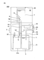
- FIG. 1 is a schematic view showing a beverage server 100 according to an embodiment.
- the beverage server 100 according to the present disclosure is configured to supply hot beverages from the first cock 2A and cold beverages from the second cock 2B.
- the beverage server 100 can use, for example, a shrinkable beverage container or a non-shrinkable beverage container as the beverage container 1.
- the "shrinkable beverage container” may mean a container that contracts as the beverage is poured out.
- the "shrinkable beverage container” can be, for example, a BIB (Bag In Box).
- the BIB can have, for example, a container made of flexible resin in a paper box.
- the "non-shrinkable beverage container” can mean a container that does not shrink with the pouring of the beverage, unlike the shrinkable container.
- the “non-shrinkable beverage container” can be, for example, a plastic bottle made of plastic such as polyethylene terephthalate (PET), polypropylene (PP) or polyethylene (PE).
- PET polyethylene terephthalate
- PP polypropylene
- PE polyethylene
- the beverage container 1 has a mouth portion 11 for pouring out the beverage.
- the mouth portion 11 may be sealed before use.
- the beverage container 1 is supported by the beverage server 100 so that the mouth portion 11 faces downward during use.
- the mouth portion 11 of the beverage container 1 is configured so that the needle N (detailed later) of the beverage server 100 can penetrate.
- the beverage container 1 can contain various beverages (for example, water, coffee, tea, soft drinks, etc.).
- the capacity of the beverage container 1 is, for example, 500 ml to 20 L.
- the beverage container 1 is shown as a simple cylinder in FIG. 1 for ease of understanding, it should be noted that the beverage container 1 may have various shapes such as a general PET bottle shape.
- the beverage server 100 includes a first cock 2A, a second cock 2B, a cooling chamber (support portion) 31, a cooling device 33, a first pipe 41, a second pipe 42, and a third. It includes a pipe 43, a tank 5, a sterilizer heater 6, and a control device 7.
- the beverage server 100 may further have other components.
- the cooling chamber 31 is configured to accommodate and support the beverage container 1.
- the cooling chamber 31 is located above the tank 5, and therefore the beverage container 1 is located above the tank 5.
- the cooling device 33 is provided inside the cooling chamber 31, and the cooling chamber 31 is insulated from the outside.
- the inside of the cooling chamber 31 can be maintained at a low temperature (for example, 10 ° C. or lower), and therefore the beverage inside the beverage container 1 can be kept at a low temperature.
- the first pipe 41 connects the beverage container 1 of the cooling chamber 31 and the tank 5 (details will be described later).
- a needle N is connected to one end (upper end) of the first pipe 41.
- the needle N is configured to penetrate the mouth portion 11 of the beverage container 1. With such a configuration, the beverage inside the beverage container 1 is poured into the first pipe 41 and replenished in the tank 5.
- the second pipe 42 connects the beverage container 1 of the cooling chamber 31 and the second cock 2B.
- the second pipe 42 is connected to the beverage container 1 without going through the tank 5, and is configured to supply the cold beverage from the beverage container 1 to the second cock 2B without going through the tank 5. .. More specifically, the second pipe 42 is connected to the first pipe 41 between the beverage container 1 and the tank 5.
- the sterilization heater 6 is arranged in the second pipe 42. The sterilization heater 6 is configured to heat the beverage inside the second pipe 42.
- the tank 5 stores the beverage from the beverage container 1.
- the tank 5 is arranged below the beverage container 1.
- the tank 5 has a heater 51 for heating the stored beverage.
- the tank 5 has an intake port 52 for taking in a gas from the outside (for example, air around the tank 5).
- the intake port 52 may include a filter (not shown) for removing contaminants from the gas taken in.
- the third pipe 43 connects the tank 5 and the first cock 2A.
- One end (lower end) of the third pipe 43 is designed to be arranged inside the tank 5, more specifically, at a position slightly lower than the liquid level L of the beverage inside the tank 5. It is configured to take in hotter beverages at higher positions.
- the control device 7 is configured to control the components of the beverage server 100.
- the control device 7 may be able to communicate with the first cock 2A, the second cock 2B, and the valve V (details will be described later) by wire or wirelessly, and is configured to control the opening and closing of these. You may be.
- the control device 7 may be able to communicate with the heater 51 and the sterilization heater 6 by wire or wirelessly, and may be configured to control their on / off and temperature.
- the control device 7 may have a hot beverage supply mode, a cold beverage supply mode, a sterilization mode, and a standby mode.
- the control device 7 may have a button for initiating the hot beverage supply mode.
- control device 7 may have a button for initiating the cold beverage supply mode. Further, the control device 7 may be configured to automatically start the sterilization mode at predetermined intervals (for example, several hours, one day or several days, or one week or several weeks). Alternatively or additionally, the control device 7 may have a button for initiating the sterilization mode. The control device 7 may be in the standby mode except when the hot beverage supply mode, the cold beverage supply mode, and the sterilization mode are being executed.
- the control device 7 may include, for example, a processor, a memory, and / or an operation unit.
- the processor can include, for example, one or more CPUs (Central Processing Units). Independent integrated circuits, microprocessors, and / or firmware may be used instead of the processor.
- the memory can include, for example, a ROM (Read Only Memory) such as a flash memory and a storage device such as a RAM (Random Access Memory).
- the memory can store various programs executed by the processor.
- the program is installed in memory from a computer-readable portable recording medium such as a CD-ROM (CompactDiskReadOnlyMemory) or DVD-ROM (DigitalVersatileDiskReadOnlyMemory) using a known setup program or the like. You may.
- the operation unit can have an input function and a display function, and can include, for example, a touch panel. Alternatively or additionally, the operating unit may include other components (eg, a liquid crystal display and / or a button, etc.
- the other end (lower end) of the first pipe 41 is arranged inside the tank 5.
- a flat plate (which may also be referred to as an interfering plate) 41b is attached to the other end of the first pipe 41, and the flat plate 41b is arranged near the bottom of the tank 5.
- the first pipe 41 has a valve V between the beverage container 1 and the tank 5. More specifically, the valve V is provided in the first pipe 41 between the connection portion of the first pipe 41 and the second pipe 42 and the tank 5.
- the valve V can be, for example, a solenoid valve. As described above, the opening and closing of the valve V is controlled by, for example, the control device 7.
- the first pipe 41 has a gas inflow hole 41a for allowing gas (for example, air) G to flow into the beverage container 1.
- gas for example, air
- the gas inflow hole 41a is provided in the first pipe 41 at a position inside the tank 5.
- the gas inflow hole 41a may include one or more holes penetrating the wall surface of the first pipe 41.
- the gas inflow hole 41a is configured to allow the passage of gas, but not to allow the passage of beverages flowing inside the first pipe 41 due to surface tension.
- the first pipe 41 may have an inner diameter of 5 to 10 mm, while the gas inflow hole 41a may have a diameter of 0.5 to 3 mm (for example, about 1 mm in diameter).
- "not allowing the passage of beverages” means that the beverage container 1 is housed in the cooling chamber 31 and no external force is applied to the beverage container 1 from other elements (for example, the user). It can mean that the beverage does not leak from the gas inflow hole 41a to the outside of the first pipe 41. For example, depending on the pressing force applied to the beverage container 1 by the user when the beverage container 1 is replaced, the beverage flows into the gas. Note that it may leak from hole 41a.
- the beverage server 100 may be in the standby mode except when the hot beverage supply mode, the cold beverage supply mode, and the sterilization mode are being executed.
- the beverage server 100 When the beverage server 100 is in standby mode, all of the first cock 2A, the second cock 2B and the valve V are closed. Further, when the beverage server 100 is in the standby mode, the heater 51 is turned on and the sterilizing heater 6 is turned off. In this state, the beverage server 100 does not move the beverage. Further, since the heat from the heater 51 of the tank 5 is also cut off by the valve V, the heat is not transferred from the tank 5 to the beverage container 1.
- the button for starting the hot beverage supply mode may be pressed as described above.
- the control device 7 opens the first cock 2A and the valve V.
- the hot beverage inside the tank 5 is pushed out to the third pipe 43 by the weight of the beverage inside the beverage container 1 and the first pipe 41, and the hot beverage is supplied from the first cock 2A. ..
- the gas G enters the first pipe 41 from the inside of the tank 5 through the gas inflow hole 41a, the gas G flows into the beverage container 1 through the first pipe 41, and the gas G flows from the beverage container 1.
- Beverages are replenished in the tank 5 via the first pipe 41.
- the control device 7 closes the first cock 2A and the valve V again. By this operation, the replenishment of the beverage from the beverage container 1 to the tank 5 is stopped.
- the button for starting the cold beverage supply mode may be pressed as described above.
- the control device 7 opens the second cock 2B and the valve V.
- the cold beverage inside the beverage container 1 is supplied from the second cock 2B via the second pipe 42.
- the gas G enters the first pipe 41 from the inside of the tank 5 through the gas inflow hole 41a, and the gas G flows into the beverage container 1 through the first pipe 41.
- the control device 7 closes the second cock 2B and the valve V again. By this operation, the supply of the beverage from the beverage container 1 to the second cock 2B is stopped.
- the sterilization mode may be executed at predetermined intervals as described above, or when the button for starting the sterilization mode is pressed.
- the control device 7 turns on the sterilization heater 6.
- the heat from the sterilizing heater 6 goes to the needle N via the second pipe 42 and the first pipe 41, and the needle N is sterilized.
- the sterilization mode may be automatically terminated after a predetermined period of time (eg, 1 minute or minutes, or 1 hour or hours).
- a predetermined period of time eg, 1 minute or minutes, or 1 hour or hours.
- a valve V is provided in the first pipe 41 between the beverage container 1 to be cooled and the tank 5 to be heated. Therefore, by closing the valve V except when necessary, it is possible to prevent the heat from the hot beverage in the tank 5 from being transferred to the beverage container 1. Therefore, the cooling efficiency of the beverage container 1 can be maintained.
- the beverage server 100 uses a non-shrinkable beverage container 1 as a beverage source, and the first pipe 41 has a gas inflow hole 41a that allows the passage of gas and does not allow the passage of beverage. ..
- the beverage server 100 uses the non-shrinkable beverage container 1 as the beverage source, when the beverage is replenished from the beverage container 1 to the tank 5, air is introduced into the beverage container 1. Configuration is required.
- a gas inflow hole 41a that allows the passage of gas and does not allow the passage of beverage is provided in the first pipe 41 for sending the beverage from the upper beverage container 1 to the lower tank 5. ..
- the beverage server 100 does not need to attach a dedicated cap to the beverage container 1 or to make a hole in each beverage container 1 in order to allow gas to flow into the beverage container 1. Therefore, the non-shrinkable beverage container 1 can be used with a simple structure.
- the lower end of the first pipe 41 is arranged inside the tank 5, and the gas inflow hole 41a is provided in the first pipe 41 at a position inside the tank 5.
- the beverage container 1 when the beverage container 1 is arranged in the cooling chamber 31 when the beverage container 1 is replaced, the beverage container 1 may be pressed by the user. Depending on the pressing force, the beverage may be pushed out of the beverage container 1 into the first pipe 41, and the beverage may leak from the gas inflow hole 41a.
- the gas inflow hole 41a is located inside the tank 5, the beverage leaking from the gas inflow hole 41a can be guided to the inside of the tank 5.
- the beverage server 100 includes a first cock 2A for hot beverages and a second cock 2B for cold beverages, and the first cock 2A is connected to the tank 5 and starts from the tank 5.
- the second cock 2B is connected to the beverage container 1 without going through the tank 5, and is configured to supply the cold beverage from the beverage container 1 without going through the tank 5. It is configured in. Therefore, the beverage server 100 can supply two beverages including a hot beverage from the first cock 2A and a cold beverage from the second cock 2B. Further, the beverage server 100 supplies beverages from the common beverage container 1 to both the tank 5 (first cock 2A) and the second cock 2B. The beverage container 1 is cooled by the cooling device 33.
- the beverage server 100 can reduce the microorganisms in the beverage supplied to the tank 5, so that the change in the flavor of the hot beverage heated in the tank 5 can be prevented.
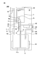
- FIG. 2 is a schematic view showing a beverage server 200 according to another embodiment.
- the beverage server 200 is different from the beverage server 100 in that it includes a fourth pipe (air supply pipe) 44 in place of the gas inflow hole 41a as a configuration for sending gas to the beverage container 1.
- a fourth pipe (air supply pipe) 44 in place of the gas inflow hole 41a as a configuration for sending gas to the beverage container 1.
- the fourth pipe 44 is configured to connect the beverage container 1 and the tank 5 and send gas (for example, air) G from the inside of the tank 5 to the beverage container 1.
- a needle N2 is connected to one end (upper end) of the fourth pipe 44.
- the needle N2 is configured to penetrate the mouth portion 11 of the beverage container 1. With such a configuration, the gas G inside the tank 5 is supplied to the beverage container 1.
- the fourth pipe 44 is connected to the upper part (upper surface) of the tank 5 and is configured to take in the gas in the upper part of the tank 5.
- the fourth pipe 44 is configured to allow the passage of gas but not the ingress of beverages from the needle N2 due to surface tension.
- the first pipe 41 for sending a beverage has an inner diameter of 5 to 10 mm
- the fourth pipe 44 for sending a gas has an inner diameter of 0.5 to 3 mm (for example, about 2 mm in inner diameter). be able to. If the inner diameter of the fourth pipe 44 is too large (for example, if it is larger than 3 mm), water may enter the fourth pipe 44.
- the inner diameter of the fourth pipe 44 is too small (for example, if it is smaller than 0.5 mm), the flow rate of the gas entering the fourth pipe 44 may not be sufficient, and the beverage container 1 to the tank 5 may be insufficient. Beverages may not be supplied to.
- the fourth pipe 44 has a second valve V2 between the tank 5 and the beverage container 1.
- the second valve V2 can be, for example, a solenoid valve.
- the opening and closing of the second valve V2 is controlled by, for example, the control device 7.
- the control device 7 opens the first cock 2A, the valve V, and the second valve V2.
- the hot beverage inside the tank 5 is pushed out to the third pipe 43 by the weight of the beverage inside the beverage container 1 and the first pipe 41, and the hot beverage is supplied from the first cock 2A. ..
- the gas G enters the fourth pipe 44 from the inside of the tank 5, the gas G flows into the beverage container 1 through the fourth pipe 44, and the gas G flows from the beverage container 1 through the first pipe 41.
- the tank 5 is refilled with beverage.
- the control device 7 closes the first cock 2A, the valve V, and the second valve V2 again. By this operation, the inflow of the gas G from the fourth pipe 44 into the beverage container 1 is stopped, and the replenishment of the beverage from the beverage container 1 to the tank 5 is also stopped.
- the control device 7 opens the second cock 2B and the second valve V2. By this operation, the cold beverage inside the beverage container 1 is supplied from the second cock 2B via the second pipe 42. Further, the gas G enters the fourth pipe 44 from the inside of the tank 5, and the gas G flows into the beverage container 1 through the fourth pipe 44.
- the control device 7 closes the second cock 2B and the second valve V2 again. By this operation, the inflow of the gas G from the fourth pipe 44 into the beverage container 1 is stopped, and the supply of the beverage from the beverage container 1 to the second cock 2B is also stopped.
- the control device 7 opens only the valve V. By this operation, heat can be transferred from the tank 5 through the first pipe 41, but since the second valve V2 is closed, the gas G from the fourth pipe 44 to the beverage container 1 can be transferred. The inflow is stopped and therefore the replenishment of the beverage from the beverage container 1 to the tank 5 is also stopped. Therefore, the heat from the heater 51 of the tank 5 efficiently goes to the needle N1 through the first pipe 41. Further, the control device 7 turns on the sterilization heater 6. The heat from the sterilization heater 6 goes to the needle N1 via the second pipe 42 and the first pipe 41. When the sterilization mode ends, the control device 7 closes the valve V again and turns off the sterilization heater 6.
- a valve V is provided in the first pipe 41 between the beverage container 1 to be cooled and the tank 5 to be heated. Therefore, by closing the valve V except when necessary, it is possible to prevent the heat from the hot beverage in the tank 5 from being transferred to the beverage container 1. Therefore, the cooling efficiency of the beverage container 1 can be maintained.
- the beverage server 200 uses a non-shrinkable beverage container 1 as a beverage source, and the beverage server 200 is a fourth pipe 44 for sending gas to the beverage container 1 and allows the passage of gas. Moreover, a fourth pipe 44 that does not allow the passage of beverages is further provided. Therefore, when the beverage is poured out from the tank 5 to the outside of the beverage server 200, the beverage is replenished from the beverage container 1 to the tank 5 by the weight of the beverage inside the beverage container 1 and the first pipe 41, and the first Gas is supplied to the beverage container 1 from the pipe 44 of 4.
- the beverage server 200 attaches a dedicated cap to the beverage container 1 or makes a hole in each beverage container 1 in order to allow gas to flow into the beverage container 1 when the beverage is replenished from the beverage container 1 to the tank 5. I don't need that. Therefore, the non-shrinkable beverage container 1 can be used with a simple structure.
- the beverage server 200 includes a first cock 2A for hot beverages and a second cock 2B for cold beverages, and the first cock 2A is connected to the tank 5 and starts from the tank 5.
- the second cock 2B is connected to the beverage container 1 without going through the tank 5, and is configured to supply the cold beverage from the beverage container 1 without going through the tank 5. It is configured in. Therefore, the beverage server 200 can supply two beverages, including a hot beverage from the first cock 2A and a cold beverage from the second cock 2B. Further, the beverage server 200 supplies beverages from the common beverage container 1 to both the tank 5 (first cock 2A) and the second cock 2B. The beverage container 1 is cooled by the cooling device 33.
- the beverage server 200 can reduce the microorganisms in the beverage supplied to the tank 5, so that the change in the flavor of the hot beverage heated in the tank 5 can be prevented.
- FIG. 3 is a schematic view showing the beverage server 300 according to still another embodiment.
- the fourth pipe 44 is connected to the beverage container 1 from the outside of the tank 5, and the fifth pipe 53 having the intake port 52 extends to the same height as the beverage container 1. In that respect, it differs from the beverage server 200 described above.
- the gas G enters the fourth pipe 44 from the outside of the tank 5. Therefore, the tank 5 can be filled with a beverage. Therefore, the beverage is also contained in the fifth pipe 53, and the liquid level L of the beverage in the fifth pipe 53 is equivalent to the liquid level of the beverage in the beverage container 1.
- a sterilization heater 8 is provided in the fifth pipe 53.
- the sterilization heater 8 may be the same as the sterilization heater 6, for example.
- the control device 7 may be able to communicate with the sterilization heater 8 by wire or wirelessly, and may be configured to control the on / off and temperature of the sterilization heater 8.
- the control device 7 opens the first cock 2A, the valve V, and the second valve V2.
- the hot beverage inside the tank 5 is pushed out to the third pipe 43 by the weight of the beverage inside the beverage container 1 and the first pipe 41, and the hot beverage is supplied from the first cock 2A. ..
- the gas G enters the fourth pipe 44 from the outside of the tank 5, the gas G flows into the beverage container 1 through the fourth pipe 44, and the gas G flows from the beverage container 1 through the first pipe 41.
- the tank 5 is refilled with beverage.
- the control device 7 closes the first cock 2A, the valve V, and the second valve V2 again. By this operation, the inflow of the gas G from the fourth pipe 44 into the beverage container 1 is stopped, and the replenishment of the beverage from the beverage container 1 to the tank 5 is also stopped.
- the control device 7 opens the second cock 2B and the second valve V2. By this operation, the cold beverage inside the beverage container 1 is supplied from the second cock 2B via the second pipe 42. Further, the gas G enters the fourth pipe 44 from the outside of the tank 5, and the gas G flows into the beverage container 1 through the fourth pipe 44. When the cold beverage supply mode ends, the control device 7 closes the second cock 2B and the second valve V2 again. By this operation, the inflow of the gas G from the fourth pipe 44 into the beverage container 1 is stopped, and the supply of the beverage from the beverage container 1 to the second cock 2B is also stopped.
- the control device 7 opens only the valve V, similarly to the beverage server 200 described above. Further, in the sterilization mode, the control device 7 turns on the sterilization heater 6 and the sterilization heater 8. The heat from the sterilization heater 6 goes to the needle N1 via the second pipe 42 and the first pipe 41. Further, the inside of the fifth pipe 53 can be sterilized by the heat from the sterilization heater 8. When the sterilization mode ends, the control device 7 closes the valve V again and turns off the sterilization heater 6 and the sterilization heater 8.
- the beverage server 300 as described above can exert almost the same effect as the above-mentioned effect of the beverage server 200.
- only one beverage container 1 is connected to the tank 5.
- a plurality of beverage containers 1 may be connected to the tank 5.
- a plurality of first pipes 41 may be connected to the tank 5.
- the upper end of the first pipe 41 may be branched into a plurality of parts.
Landscapes
- Engineering & Computer Science (AREA)
- Mechanical Engineering (AREA)
- Devices For Dispensing Beverages (AREA)
Abstract
Description
2A 第1のコック
2B 第2のコック
5 タンク
31 冷却室(支持部)
33 冷却装置
41 第1の配管(配管)
41a 気体流入孔
44 第4の配管(給気管)
51 ヒーター
100 飲料サーバー
200 飲料サーバー
300 飲料サーバー
G 気体
V バルブ
Claims (5)
- 飲料容器を支持する支持部と、
前記飲料容器を冷却するための冷却装置と、
前記飲料容器の下方に配置されるタンクであって、飲料を加熱するためのヒーターを有する、タンクと、
前記飲料容器から前記タンクに飲料を送るための配管と、
を備え、
前記配管は、前記タンクと前記飲料容器との間にバルブを有する、飲料サーバー。 - 当該飲料サーバーは、飲料源として非収縮性の飲料容器を使用し、
前記配管は、気体の通過を許容し且つ前記飲料の通過を許容しない気体流入孔を有する、請求項1に記載の飲料サーバー。 - 前記配管の下端は、前記タンクの内部に配置されており、
前記気体流入孔は、前記タンクの内部の位置において前記配管に設けられている、請求項2に記載の飲料サーバー。 - 当該飲料サーバーは、飲料源として非収縮性の飲料容器を使用し、
当該飲料サーバーは、
前記飲料容器に気体を送るための給気管であって、気体の通過を許容し且つ前記飲料の通過を許容しない、給気管、
を更に備える、請求項1に記載の飲料サーバー。 - 温飲料用の第1のコックと、
冷飲料用の第2のコックと、
を備え、
前記第1のコックは、前記タンクと接続され、前記タンクからの温飲料を供給するように構成されており、
前記第2のコックは、前記タンクを介さずに前記飲料容器と接続され、前記タンクを介さずに前記飲料容器からの冷飲料を供給するように構成されている、請求項1~4のいずれか一項に記載の飲料サーバー。
Priority Applications (3)
| Application Number | Priority Date | Filing Date | Title |
|---|---|---|---|
| KR1020217037550A KR20210150571A (ko) | 2019-05-21 | 2020-05-21 | 음료 서버 |
| JP2021520860A JPWO2020235654A1 (ja) | 2019-05-21 | 2020-05-21 | |
| CN202080049590.0A CN114072353A (zh) | 2019-05-21 | 2020-05-21 | 饮料机 |
Applications Claiming Priority (2)
| Application Number | Priority Date | Filing Date | Title |
|---|---|---|---|
| JP2019-095211 | 2019-05-21 | ||
| JP2019095211 | 2019-05-21 |
Publications (1)
| Publication Number | Publication Date |
|---|---|
| WO2020235654A1 true WO2020235654A1 (ja) | 2020-11-26 |
Family
ID=73458819
Family Applications (1)
| Application Number | Title | Priority Date | Filing Date |
|---|---|---|---|
| PCT/JP2020/020188 Ceased WO2020235654A1 (ja) | 2019-05-21 | 2020-05-21 | 飲料サーバー |
Country Status (4)
| Country | Link |
|---|---|
| JP (1) | JPWO2020235654A1 (ja) |
| KR (1) | KR20210150571A (ja) |
| CN (1) | CN114072353A (ja) |
| WO (1) | WO2020235654A1 (ja) |
Families Citing this family (1)
| Publication number | Priority date | Publication date | Assignee | Title |
|---|---|---|---|---|
| KR102862056B1 (ko) * | 2022-07-15 | 2025-09-18 | 지구환 | 음료용기 냉각 장치 |
Citations (2)
| Publication number | Priority date | Publication date | Assignee | Title |
|---|---|---|---|---|
| JP2014189280A (ja) * | 2013-03-26 | 2014-10-06 | Cosmo Life:Kk | ウォーターサーバー |
| JP2015110434A (ja) * | 2013-12-06 | 2015-06-18 | 株式会社Osgコーポレーション | 飲料水ディスペンサー |
Family Cites Families (8)
| Publication number | Priority date | Publication date | Assignee | Title |
|---|---|---|---|---|
| FR2785600A1 (fr) * | 1998-11-09 | 2000-05-12 | Dietal Sa | Ensemble refroidisseur pour appareil distributeur de boisson |
| JP4349985B2 (ja) | 2004-07-15 | 2009-10-21 | フジテクノ株式会社 | 飲料サーバーおよび飲料サーバー用接続部 |
| JP4464290B2 (ja) * | 2005-02-18 | 2010-05-19 | フジテクノ株式会社 | 飲料サーバー |
| JP5072039B2 (ja) * | 2008-12-16 | 2012-11-14 | フジテクノ株式会社 | 飲料サーバー |
| JP5633018B2 (ja) * | 2010-03-12 | 2014-12-03 | 一雄 古市 | 飲料サーバー |
| JP5904717B2 (ja) * | 2010-05-10 | 2016-04-20 | エア・ウォーター株式会社 | 飲料水サーバ |
| JP2016153308A (ja) * | 2013-06-19 | 2016-08-25 | 興和株式会社 | 飲料水供給装置 |
| JP6271108B1 (ja) * | 2017-07-18 | 2018-01-31 | 優 塩谷 | 飲料サーバー、および飲料サーバー用キャップ |
-
2020
- 2020-05-21 KR KR1020217037550A patent/KR20210150571A/ko not_active Abandoned
- 2020-05-21 WO PCT/JP2020/020188 patent/WO2020235654A1/ja not_active Ceased
- 2020-05-21 JP JP2021520860A patent/JPWO2020235654A1/ja active Pending
- 2020-05-21 CN CN202080049590.0A patent/CN114072353A/zh active Pending
Patent Citations (2)
| Publication number | Priority date | Publication date | Assignee | Title |
|---|---|---|---|---|
| JP2014189280A (ja) * | 2013-03-26 | 2014-10-06 | Cosmo Life:Kk | ウォーターサーバー |
| JP2015110434A (ja) * | 2013-12-06 | 2015-06-18 | 株式会社Osgコーポレーション | 飲料水ディスペンサー |
Also Published As
| Publication number | Publication date |
|---|---|
| JPWO2020235654A1 (ja) | 2020-11-26 |
| KR20210150571A (ko) | 2021-12-10 |
| CN114072353A (zh) | 2022-02-18 |
Similar Documents
| Publication | Publication Date | Title |
|---|---|---|
| CN104755413B (zh) | 饮水机 | |
| JP4335273B2 (ja) | 飲料水用サーバー | |
| JP6084484B2 (ja) | ウォーターサーバー | |
| JP2011046446A (ja) | ウォーターサーバー | |
| JP2010083582A (ja) | 飲料サーバー | |
| JP2001153523A (ja) | 飲料用温水器及び飲料用冷水器及び飲料用温水・冷水器 | |
| JP2005249266A (ja) | 飲料水のディスペンサ | |
| KR20210150571A (ko) | 음료 서버 | |
| JP5633018B2 (ja) | 飲料サーバー | |
| JP2018177285A (ja) | 飲料供給装置 | |
| TW201102028A (en) | A beverage device with a container | |
| WO2020235656A1 (ja) | 飲料サーバー | |
| US738712A (en) | Water-cooler equipment. | |
| JP5728776B2 (ja) | 加熱殺菌のできるディスペンサ | |
| JP2017154807A (ja) | 飲料供給機 | |
| JP4464290B2 (ja) | 飲料サーバー | |
| WO2019131683A1 (ja) | ウォーターサーバー及びウォーターサーバーへの給水方法 | |
| JP2005170432A (ja) | 飲料サーバー | |
| JP2017024724A (ja) | 配管内殺菌方法、配管内殺菌装置、および配管内殺菌装置を備えた飲料水供給装置 | |
| JP6136275B2 (ja) | 飲料供給方法及び飲料サーバー | |
| JP2016199327A (ja) | ウォーターサーバおよびその給水方法 | |
| CN205274217U (zh) | 储液容器 | |
| JP3089451U (ja) | 飲料水供給器 | |
| JP2013086841A (ja) | 容器のエア抜き構造及びそれを用いたウォーターサーバー | |
| KR101632413B1 (ko) | 관로 교체가 용이한 액체저장용기용 디스펜서 |
Legal Events
| Date | Code | Title | Description |
|---|---|---|---|
| 121 | Ep: the epo has been informed by wipo that ep was designated in this application |
Ref document number: 20810513 Country of ref document: EP Kind code of ref document: A1 |
|
| ENP | Entry into the national phase |
Ref document number: 2021520860 Country of ref document: JP Kind code of ref document: A |
|
| ENP | Entry into the national phase |
Ref document number: 20217037550 Country of ref document: KR Kind code of ref document: A |
|
| NENP | Non-entry into the national phase |
Ref country code: DE |
|
| 122 | Ep: pct application non-entry in european phase |
Ref document number: 20810513 Country of ref document: EP Kind code of ref document: A1 |