WO2020235439A1 - レンズ駆動装置 - Google Patents
レンズ駆動装置 Download PDFInfo
- Publication number
- WO2020235439A1 WO2020235439A1 PCT/JP2020/019249 JP2020019249W WO2020235439A1 WO 2020235439 A1 WO2020235439 A1 WO 2020235439A1 JP 2020019249 W JP2020019249 W JP 2020019249W WO 2020235439 A1 WO2020235439 A1 WO 2020235439A1
- Authority
- WO
- WIPO (PCT)
- Prior art keywords
- lens
- yoke
- coil
- magnet
- outer peripheral
- Prior art date
- Legal status (The legal status is an assumption and is not a legal conclusion. Google has not performed a legal analysis and makes no representation as to the accuracy of the status listed.)
- Ceased
Links
Images








Classifications
-
- H—ELECTRICITY
- H01—ELECTRIC ELEMENTS
- H01F—MAGNETS; INDUCTANCES; TRANSFORMERS; SELECTION OF MATERIALS FOR THEIR MAGNETIC PROPERTIES
- H01F7/00—Magnets
- H01F7/02—Permanent magnets [PM]
- H01F7/0273—Magnetic circuits with PM for magnetic field generation
- H01F7/0289—Transducers, loudspeakers, moving coil arrangements
-
- G—PHYSICS
- G02—OPTICS
- G02B—OPTICAL ELEMENTS, SYSTEMS OR APPARATUS
- G02B27/00—Optical systems or apparatus not provided for by any of the groups G02B1/00 - G02B26/00, G02B30/00
- G02B27/64—Imaging systems using optical elements for stabilisation of the lateral and angular position of the image
- G02B27/646—Imaging systems using optical elements for stabilisation of the lateral and angular position of the image compensating for small deviations, e.g. due to vibration or shake
-
- G—PHYSICS
- G02—OPTICS
- G02B—OPTICAL ELEMENTS, SYSTEMS OR APPARATUS
- G02B7/00—Mountings, adjusting means, or light-tight connections, for optical elements
- G02B7/02—Mountings, adjusting means, or light-tight connections, for optical elements for lenses
-
- G—PHYSICS
- G03—PHOTOGRAPHY; CINEMATOGRAPHY; ANALOGOUS TECHNIQUES USING WAVES OTHER THAN OPTICAL WAVES; ELECTROGRAPHY; HOLOGRAPHY
- G03B—APPARATUS OR ARRANGEMENTS FOR TAKING PHOTOGRAPHS OR FOR PROJECTING OR VIEWING THEM; APPARATUS OR ARRANGEMENTS EMPLOYING ANALOGOUS TECHNIQUES USING WAVES OTHER THAN OPTICAL WAVES; ACCESSORIES THEREFOR
- G03B5/00—Adjustment of optical system relative to image or object surface other than for focusing
-
- H—ELECTRICITY
- H01—ELECTRIC ELEMENTS
- H01F—MAGNETS; INDUCTANCES; TRANSFORMERS; SELECTION OF MATERIALS FOR THEIR MAGNETIC PROPERTIES
- H01F7/00—Magnets
- H01F7/06—Electromagnets; Actuators including electromagnets
- H01F7/066—Electromagnets with movable winding
-
- H—ELECTRICITY
- H01—ELECTRIC ELEMENTS
- H01F—MAGNETS; INDUCTANCES; TRANSFORMERS; SELECTION OF MATERIALS FOR THEIR MAGNETIC PROPERTIES
- H01F7/00—Magnets
- H01F7/06—Electromagnets; Actuators including electromagnets
- H01F7/08—Electromagnets; Actuators including electromagnets with armatures
- H01F7/081—Magnetic constructions
-
- G—PHYSICS
- G03—PHOTOGRAPHY; CINEMATOGRAPHY; ANALOGOUS TECHNIQUES USING WAVES OTHER THAN OPTICAL WAVES; ELECTROGRAPHY; HOLOGRAPHY
- G03B—APPARATUS OR ARRANGEMENTS FOR TAKING PHOTOGRAPHS OR FOR PROJECTING OR VIEWING THEM; APPARATUS OR ARRANGEMENTS EMPLOYING ANALOGOUS TECHNIQUES USING WAVES OTHER THAN OPTICAL WAVES; ACCESSORIES THEREFOR
- G03B2205/00—Adjustment of optical system relative to image or object surface other than for focusing
- G03B2205/0007—Movement of one or more optical elements for control of motion blur
-
- G—PHYSICS
- G03—PHOTOGRAPHY; CINEMATOGRAPHY; ANALOGOUS TECHNIQUES USING WAVES OTHER THAN OPTICAL WAVES; ELECTROGRAPHY; HOLOGRAPHY
- G03B—APPARATUS OR ARRANGEMENTS FOR TAKING PHOTOGRAPHS OR FOR PROJECTING OR VIEWING THEM; APPARATUS OR ARRANGEMENTS EMPLOYING ANALOGOUS TECHNIQUES USING WAVES OTHER THAN OPTICAL WAVES; ACCESSORIES THEREFOR
- G03B2205/00—Adjustment of optical system relative to image or object surface other than for focusing
- G03B2205/0007—Movement of one or more optical elements for control of motion blur
- G03B2205/0015—Movement of one or more optical elements for control of motion blur by displacing one or more optical elements normal to the optical axis
-
- G—PHYSICS
- G03—PHOTOGRAPHY; CINEMATOGRAPHY; ANALOGOUS TECHNIQUES USING WAVES OTHER THAN OPTICAL WAVES; ELECTROGRAPHY; HOLOGRAPHY
- G03B—APPARATUS OR ARRANGEMENTS FOR TAKING PHOTOGRAPHS OR FOR PROJECTING OR VIEWING THEM; APPARATUS OR ARRANGEMENTS EMPLOYING ANALOGOUS TECHNIQUES USING WAVES OTHER THAN OPTICAL WAVES; ACCESSORIES THEREFOR
- G03B2205/00—Adjustment of optical system relative to image or object surface other than for focusing
- G03B2205/0053—Driving means for the movement of one or more optical element
- G03B2205/0069—Driving means for the movement of one or more optical element using electromagnetic actuators, e.g. voice coils
Definitions
- the technology of the present disclosure relates to a lens driving device.
- Japanese Patent Laying-Open No. 2018-180285 describes a movable portion having an optical element, a coil having an opening and a surface of the opening arranged parallel to the optical axis of the optical element, and each long side of the coil.
- the first magnet and the second magnet arranged to face each other, the central yoke arranged between the first magnet and the second magnet and partly located at the opening of the coil, the first magnet and the first magnet.
- the outer yoke includes a fixing portion having an outer yoke that supplies the magnetic flux from the two magnets to the central yoke, and the outer yoke is the first outer side that is located on the opposite side of the central yoke with the first magnet in the optical axis direction.
- a yoke and a second outer yoke located on the opposite side of the central yoke with the second magnet sandwiched in the optical axis direction are included, and each of the first outer yoke and the second outer yoke is a first magnet in the optical axis direction.
- a VCM drive device in which the area overlapping the coil is smaller than the area overlapping the second magnet is disclosed.
- the correction optical means is microvibrated at a predetermined frequency higher than the runout frequency.
- the micro-vibration driving means for causing the vibration, the run-out detecting means for detecting the colliorative force generated by the angular velocity of the runout and the movement of the mass of the compensating optical means in the micro-vibration state as the displacement of the compensating optical means due to the runout, and the output of the run-out detecting means Disclosed is a vibration isolation system having an optical axis eccentricity driving means for eccentricizing the optical axis to the correction optical means based on
- a lens for vibration correction is used as compared with a case where the side surface of the yoke of the voice coil motor facing the outer peripheral surface of the lens for vibration correction is a flat surface without a recess.
- a lens driving device that can be brought close to the yoke.
- the first aspect according to the technique of the present disclosure is a holding portion for holding a lens for vibration correction from the outer peripheral side of the lens, a plurality of coil motors arranged along the circumferential direction of the lens with respect to the holding portion, and the like.
- the coil motor is a coil having a magnet, a yoke forming a magnetic flux together with the magnet, and an air core portion, and is fixed to a holding portion and the yoke is inserted through the air core portion to be energized.
- a coil that moves the holding portion in the lens radial direction by generating thrust from the current and magnetic flux, and the yoke is in the direction in which the side surface of the yoke facing the outer peripheral surface of the lens is separated from the optical axis of the lens. It is a lens driving device having a concave portion formed in a concave shape.
- the second aspect according to the technique of the present disclosure is the lens driving device according to the first aspect, wherein the protruding end portion of the recess protrudes from the coil toward the outer peripheral surface side.
- the third aspect according to the technique of the present disclosure is the lens driving device according to the second aspect in which the tip portion protrudes from the coil toward the outer peripheral surface side at the initial position of the coil.
- the fourth aspect according to the technique of the present disclosure is the lens driving device according to the second aspect or the third aspect in which the tip portion protrudes from the coil toward the outer peripheral surface side within the movable range of the coil.
- a fifth aspect according to the technique of the present disclosure is a lens driving device according to any one of the second to fourth aspects, wherein the tip portion is both ends of a recess in the tangential direction of the outer periphery of the lens. is there.
- a sixth aspect according to the technique of the present disclosure is a lens driving device according to any one of the first to fifth aspects, wherein the recess is recessed along the outer peripheral shape of the holding portion.
- the seventh aspect according to the technique of the present disclosure is the lens driving device according to the sixth aspect, wherein the outer peripheral shape is an annular shape or an arc shape, and the concave portion is concave in an arc shape.
- An eighth aspect according to the technique of the present disclosure is that the magnets are on the first magnet provided on the first direction side along the optical axis of the yoke and on the second direction side in the direction opposite to the first direction of the yoke.
- a lens according to any one of the first to seventh aspects which has a second magnet provided, and the first magnet and the second magnet are arranged so that the same magnetic poles face each other with the yoke interposed therebetween. It is a drive device.
- a ninth aspect according to the technique of the present disclosure is a first-direction side yoke provided on the first direction side of the first magnet, a second-direction side yoke provided on the second direction side of the second magnet, and the like.
- the end face on the lens side of the yoke on the first direction side and the end face on the lens side of the yoke on the second direction side are closer to the optical axis than the end point on the lens side in the movable range of the coil.
- the lens driving device according to the eighth aspect located in.
- a tenth aspect according to the technique of the present disclosure is a lens driving device according to any one of the first to ninth aspects, wherein the coil is formed by bending along the outer peripheral shape of the holding portion. ..
- the eleventh aspect according to the technique of the present disclosure is the tenth aspect in which at least one end of both ends of the coil in the tangential direction of the outer circumference of the lens is bent along the outer peripheral shape of the holding portion.
- This is a lens driving device according to the above.
- the twelfth aspect according to the technique of the present disclosure is the lens driving device according to the eleventh aspect, in which at least one end of both ends is bent in a direction approaching the optical axis.
- the thirteenth aspect according to the technique of the present disclosure is from the first aspect in which the magnet and the yoke are fixed to the housing, the coil is fixed to the holding portion, and the holding portion is movably supported with respect to the housing.
- the lens driving device according to any one of the twelfth aspects.
- a fourteenth aspect according to the technique of the present disclosure is a lens driving device according to any one of the first to thirteenth aspects, wherein the coil has a receiving recess for receiving the outer peripheral portion of the holding portion.
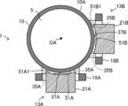
- FIG. 5 is a plan view of the lens driving device according to the first embodiment as viewed from a direction along the optical axis.
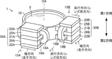
- FIG. 2 is a sectional view taken along the line AA of the lens driving device shown in FIG. It is a side view of the lens driving device which concerns on 1st Embodiment.
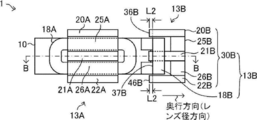
- FIG. 4 is a sectional view taken along line BB of the lens driving device shown in FIG.
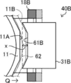
- FIG. 5 is a partial schematic view showing a change in the distance between the holding frame of the lens driving device and the yoke shown in FIG. It is a side view of the lens driving device which concerns on 2nd Embodiment.
- FIG. 1 is a plan view of the lens driving device according to the first embodiment as viewed from a direction along the optical axis.
- FIG. 2 is a sectional view taken along the line AA of the lens driving device shown in FIG. It is a side view of the lens driving device which concerns on 1st Embodiment.
- FIG. 4 is a section
- FIG. 7 is a cross-sectional view taken along the line CC of the lens driving device shown in FIG.
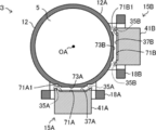
- FIG. 5 is a partial schematic view showing a change in the distance between the holding frame of the lens driving device and the yoke shown in FIG. It is a side view of the lens driving device which concerns on 3rd Embodiment.
- FIG. 10 is a cross-sectional view taken along the line DD of the lens driving device shown in FIG. It is a partial schematic view which shows the change of the distance between the holding frame of a lens driving device and a yoke shown in FIG.
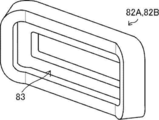
- FIG. 5 is a cross-sectional view showing the coil according to the first embodiment replaced with the coil according to the fourth embodiment shown in FIG. It is a perspective view of the coil which concerns on 5th Embodiment. It is a vertical sectional view of the coil and the holding frame which concerns on 5th Embodiment.
- An imaging device such as a digital camera is provided with a shake correction device for correcting shake due to camera shake or the like.
- a method of correcting the runout there are an optical correction method and an electronic correction method.
- the optical correction method is a method in which a correction lens for vibration correction is arranged in an optical system and the correction lens is moved in a direction for canceling the vibration to correct the vibration.
- the lens driving device that moves the correction lens by the optical correction method is incorporated in the optical system of the imaging device, it is desired to be as small as possible.
- the lens driving device is required to correct the runout (hereinafter, also referred to as “shake correction”) as quickly and accurately as possible.
- shake correction In order to perform the shake correction quickly, it is necessary to increase the thrust for driving the lens driving device, and in order to perform the shake correction accurately, it is necessary to control the position of the correction lens with high accuracy.
- a voice coil motor that is small and can obtain a large thrust is used.
- the thrust of the voice coil motor increases as the coil approaches the magnet and decreases as the coil moves away from the magnet, making it difficult to keep the thrust constant.
- the reason why the thrust changes depending on the positional relationship between the coil and the magnet is that the degree of overlap between the magnetic flux generated from the coil and the magnetic flux generated from the magnet changes depending on the positional relationship between the coil and the magnet.
- the thrust of the voice coil motor changes depending on the positional relationship between the coil and the magnet, in other words, the position of the correction lens, which causes the feedback control that drives the correction lens to correct the runout becomes difficult.
- the position of the correction lens which causes the feedback control that drives the correction lens to correct the runout becomes difficult.
- it is necessary to suppress the change in thrust depending on the position of the correction lens it is necessary to suppress the change in the degree of overlap between the magnetic flux of the coil and the magnetic flux of the magnet depending on the position of the correction lens.
- the meaning of “parallel” includes not only the meaning of perfect matching parallelism but also the meaning of substantially parallelism including errors allowed in design and manufacturing.
- the meaning of “match” includes not only the meaning of perfect match but also the meaning of substantially match including errors allowed in design and manufacturing.
- the meaning of “identical” includes not only the completely identical meaning but also substantially the same meaning including errors allowed in design and manufacturing.
- the lens driving device 1 is arranged and used in the optical system of the imaging device.
- the lens driving device 1 is applicable not only to the optical system of the image pickup device but also to the optical system of the distance measuring device, for example.
- a first direction and a second direction are defined for the lens driving device 1.
- the "first direction” refers to one direction of the optical axis OA (in the example shown in FIG. 1, the direction toward the upper side of the figure along the optical axis OA).
- the “second direction” refers to the other direction of the optical axis OA (in the example shown in FIG. 1, the direction toward the lower side of the figure along the optical axis OA). That is, the second direction means the direction opposite to the first direction.
- the lens driving device 1 has a holding frame 10, a first voice coil motor 13A, and a second voice coil motor 13B.
- the voice coil motor is also referred to as "VCM” (Voice Coil Motor).
- VCM13A and the second VCM13B are examples of “plurality of coil motors” according to the technique of the present disclosure.
- the holding frame 10 holds a lens 5 for vibration correction (hereinafter, simply referred to as "lens 5"). Specifically, the holding frame 10 holds the lens 5 from the outer peripheral side of the lens 5. In the example shown in FIG. 1, the entire outer circumference of the lens 5 is held by the holding frame 10. The holding frame 10 does not necessarily have to hold the entire outer circumference of the lens 5, and may partially hold the outer circumference of the lens 5.
- the holding frame 10 is an example of a "holding portion (holder)" according to the technique of the present disclosure.
- the optical axis OA of the lens 5 coincides with the optical axis of the optical system in which the lens driving device 1 is arranged.
- the initial lens position refers to the position of the lens 5 in a state where movement control for vibration correction is not performed.
- the configuration when the lens 5 is in the initial position of the lens will be described.
- the first VCM 13A and the second VCM 13B are arranged along the circumferential direction of the lens 5 with respect to the holding frame 10.
- the holding frame 10 is movably supported by a housing 100 (see FIG. 2) that holds the optical system in which the lens driving device 1 is arranged so as to be movable in a direction intersecting the optical axis of the optical system.
- the direction intersecting the optical axis of the optical system the direction orthogonal to the optical axis is adopted. Since a known method can be used for the structure that movably supports the lens driving device 1 to the housing 100, detailed description thereof will be omitted in the present specification.
- the first VCM 13A includes a first VCM magnet portion 30A and a first coil 18A.
- the first VCM magnet portion 30A is fixed to the housing 100.
- the first coil 18A is fixed to the holding frame 10.
- the first coil 18A is an example of a "coil" according to the technique of the present disclosure.
- the first VCM magnet portion 30A includes a first upper yoke 20A, a first middle yoke 21A, a first lower yoke 22A, a first upper magnet 25A, and a first lower magnet 26A.
- the first upper yoke 20A, the first middle yoke 21A, and the first lower yoke 22A are examples of "yoke” according to the technique of the present disclosure.
- the first upper yoke 20A is an example of the "first direction side yoke" according to the technique of the present disclosure.
- the first lower yoke 22A is an example of the "second direction side yoke" according to the technique of the present disclosure.
- the first upper magnet 25A and the first lower magnet 26A are examples of "magnets” according to the technique of the present disclosure.
- the first upper magnet 25A is an example of the "first magnet” according to the technique of the present disclosure.
- the first lower magnet 26A is an example of the "second magnet” according to the technique of the present disclosure.
- the first upper yoke 20A, the first middle yoke 21A, and the first lower yoke 22A are arranged in order from the first direction side to the second direction side along the optical axis OA.
- the first upper magnet 25A is provided on the first direction side
- the first lower magnet 26A is provided on the second direction side.
- the first upper yoke 20A is provided on the first direction side of the first upper magnet 25A
- the first lower yoke 22A is provided on the second direction side of the first lower magnet 26A.
- the first upper magnet 25A is interposed between the first upper yoke 20A and the first middle yoke 21A
- the first lower magnet 26A is between the first middle yoke 21A and the first lower yoke 22A.
- the first upper yoke 20A, the first upper magnet 25A, the first middle yoke 21A, the first lower magnet 26A, and the first lower yoke 22A are from the first direction side to the second direction side along the optical axis OA. They are stacked in order.
- the first upper yoke 20A, the first lower yoke 22A, the first upper magnet 25A, and the first lower magnet 26A are all formed in a rectangular parallelepiped shape.
- the first upper yoke 20A and the first lower yoke 22A are formed in the same shape and the same size.
- the first middle yoke 21A is thicker than the first upper yoke 20A and the first lower yoke 22A (see also FIG. 3).
- the first middle yoke 21A, the first upper yoke 20A, and the first lower yoke 22A when the first VCM magnet portion 30A is viewed from the center side of the lens 5, the first middle The yoke 21A, the first upper yoke 20A, and the first lower yoke 22A are the same.
- first upper yoke 20A In the first upper yoke 20A, one side surface (end surface 36A in the example shown in FIG. 3) extending in the longitudinal direction of the side surface of the first upper yoke 20A is directed to the outer peripheral surface side of the lens 5, and the first upper yoke 20A is formed.
- the yoke 20A is arranged so that the thickness direction and the optical axis OA direction coincide with each other.
- the first middle yoke 21A and the first lower yoke 22A are also arranged in the same posture as the first upper yoke 20A.
- the side surface of the lens 5 that is farthest from the outer peripheral surface of the lens 5 is parallel to the optical axis OA and is flush with each other.
- the first upper magnet 25A and the first lower magnet 26A in the depth direction when the first VCM magnet portion 30A is viewed from the center side of the lens 5 are the same. Yes (see also Figure 3).
- the lengths of the first upper magnet 25A and the first lower magnet 26A in the width direction when the first VCM magnet portion 30A is viewed from the center side of the lens 5 are also the same.
- the lengths of the first upper magnet 25A and the first lower magnet 26A in the depth direction are such that the first VCM magnet portion 30A is viewed from the center side of the lens 5. It is shorter than the length of the first middle yoke 21A in the depth direction (see also FIG. 3).
- the side surface of the first upper magnet 25A that is farthest from the outer peripheral surface of the lens 5 and the side surface of the first lower magnet 26A that is farthest from the outer peripheral surface of the lens 5 are on the optical axis OA. They are parallel along the line and are flush with each other (see also FIG. 3).
- the side surface of the first upper magnet 25A that is farthest from the outer peripheral surface of the lens 5 and the side surface of the first lower magnet 26A that is farthest from the outer peripheral surface of the lens 5 are the first.
- the first upper yoke 20A, the first middle yoke 21A, the first lower yoke 22A, the first upper magnet 25A, and the first lower magnet 26A By arranging the first upper yoke 20A, the first middle yoke 21A, the first lower yoke 22A, the first upper magnet 25A, and the first lower magnet 26A in this way, the first upper yoke 20A and the first middle yoke A space is formed between the 21A and the first coil 18A on the outer peripheral surface side of the lens 5 with respect to the first upper magnet 25A. Further, also between the first middle yoke 21A and the first lower yoke 22A, a space where the first coil 18A can be arranged is formed on the outer peripheral surface side of the lens 5 with respect to the first lower magnet 26A.
- the first upper yoke 20A, the first middle yoke 21A, and the first lower yoke 22A are made of a magnetic material, and form a magnetic flux together with the first upper magnet 25A and the first lower magnet 26A.
- the first upper magnet 25A and the first lower magnet 26A are arranged so that the same magnetic poles face each other with the first middle yoke 21A interposed therebetween. That is, the magnetic pole on the side of the first upper magnet 25A in contact with the first middle yoke 21A and the magnetic pole on the side of the first lower magnet 26A in contact with the first middle yoke 21A are the same.
- the first coil 18A has an air core portion 19A.
- the first coil 18A has an air core portion 19A in a direction orthogonal to the optical axis OA, and is arranged so that the longitudinal direction coincides with the tangential direction of the outer circumference of the lens 5.
- the first coil 18A is arranged between the first upper yoke 20A and the first lower yoke 22A with the first middle yoke 21A inserted through the air core portion 19A.
- the second VCM 13B includes a second VCM magnet portion 30B and a second coil 18B.
- the second VCM magnet portion 30B is fixed to the housing 100.
- the second coil 18B is fixed to the holding frame 10.
- the second coil 18B is an example of a "coil" according to the technique of the present disclosure.
- the second VCM magnet portion 30B includes a second upper yoke 20B, a second middle yoke 21B, a second lower yoke 22B, a second upper magnet 25B, and a second lower magnet 26B.
- the second upper yoke 20B, the second middle yoke 21B, and the second lower yoke 22B are examples of the "yoke” according to the technique of the present disclosure.
- the second upper yoke 20B is an example of the "first direction side yoke" according to the technique of the present disclosure.
- the second lower yoke 22B is an example of the "second direction side yoke" according to the technique of the present disclosure.
- the second upper magnet 25B and the second lower magnet 26B are examples of "magnets" according to the technique of the present disclosure.
- the second upper magnet 25B is an example of the "first magnet” according to the technique of the present disclosure.
- the second lower magnet 26B is an example of the "second magnet” according to the technique of the present disclosure.
- the second upper yoke 20B, the second middle yoke 21B, and the second lower yoke 22B are arranged in order from the first direction side to the second direction side along the optical axis OA.
- the second upper magnet 25B is provided on the first direction side
- the second lower magnet 26B is provided on the second direction side.
- the second upper yoke 20B is provided on the first direction side of the second upper magnet 25B
- the second lower yoke 22B is provided on the second direction side of the second lower magnet 26B.
- the second upper magnet 25B is interposed between the second upper yoke 20B and the second middle yoke 21B
- the second lower magnet 26B is between the second middle yoke 21B and the second lower yoke 22B.
- the second upper yoke 20B, the second upper magnet 25B, the second middle yoke 21B, the second lower magnet 26B, and the second lower yoke 22B are from the first direction side to the second direction side along the optical axis OA. They are stacked in order.
- the second upper yoke 20B, the second lower yoke 22B, the second upper magnet 25B, and the second lower magnet 26B are all formed in a rectangular parallelepiped shape.
- the second upper yoke 20B and the second lower yoke 22B are formed in the same shape and the same size.
- the second middle yoke 21B is thicker than the second upper yoke 20B and the second lower yoke 22B (see also FIG. 4).
- the second middle yoke 21B, the second upper yoke 20B, and the second lower yoke 22B are the same.
- one side surface (end surface 36B in the example shown in FIG. 4) extending in the longitudinal direction of the side surface of the second upper yoke 20B is directed to the outer peripheral surface side of the lens 5, and the second upper yoke 20B
- the yoke 20B is arranged so that the thickness direction and the optical axis OA direction coincide with each other.
- the second middle yoke 21B and the second lower yoke 22B are also arranged in the same posture as the second upper yoke 20B.
- the side surface of the lens 5 that is farthest from the outer peripheral surface of the lens 5 is parallel to the optical axis OA and is flush with each other (see also FIG. 4).
- the lengths of the second upper magnet 25B and the second lower magnet 26B in the depth direction when the second VCM magnet portion 30B is viewed from the center side of the lens 5 are the same for the second upper magnet 25B and the second lower magnet 26B. Yes (see also Figure 4).
- the lengths of the second upper magnet 25B and the second lower magnet 26B in the width direction when the second VCM magnet portion 30B is viewed from the center side of the lens 5 are also the same.
- the length of the second upper magnet 25B and the second lower magnet 26B in the depth direction when the second VCM magnet portion 30B is viewed from the center side of the lens 5 is such that the second VCM magnet portion 30B is viewed from the center side of the lens 5. It is shorter than the length of the second middle yoke 21B in the depth direction (see also FIG. 4).
- the side surface of the second upper magnet 25B that is farthest from the outer peripheral surface of the lens 5 and the side surface of the second lower magnet 26B that is farthest from the outer peripheral surface of the lens 5 are on the optical axis OA. They are parallel along the line and are flush with each other (see also FIG. 4).
- the side surface of the second upper magnet 25B that is farthest from the outer peripheral surface of the lens 5 and the side surface of the second lower magnet 26B that is farthest from the outer peripheral surface of the lens 5 are the second.
- the second upper yoke 20B, the second middle yoke 21B, the second lower yoke 22B, the second upper magnet 25B, and the second lower magnet 26B are arranged.
- a space is formed between the 21B and the second coil 18B on the outer peripheral surface side of the lens 5 with respect to the second upper magnet 25B.
- a space where the second coil 18B can be arranged is formed on the outer peripheral surface side of the lens 5 with respect to the second lower magnet 26B.
- the second upper yoke 20B, the second middle yoke 21B, and the second lower yoke 22B are made of a magnetic material, and form a magnetic flux together with the second upper magnet 25B and the second lower magnet 26B.
- the second upper magnet 25B and the second lower magnet 26B are arranged so that the same magnetic poles face each other with the second middle yoke 21B interposed therebetween. That is, the magnetic pole on the side of the second upper magnet 25B in contact with the second middle yoke 21B and the magnetic pole on the side of the second lower magnet 26B in contact with the second middle yoke 21B are the same.
- the second coil 18B has an air core portion 19B.
- the second coil 18B has an air core portion 19B in a direction orthogonal to the optical axis OA, and is arranged so that the longitudinal direction coincides with the tangential direction of the outer circumference of the lens 5.
- the second coil 18B is arranged between the second upper yoke 20B and the second lower yoke 22B with the second middle yoke 21B inserted through the air core portion 19B.
- the first VCM13A and the second VCM13B are arranged so that the angle seen from the center side of the lens 5 is a right angle (90 degrees in the example shown in FIG. 2).
- the holding frame 10 receives the power generated by the first VCM 13A and / or the second VCM 13B in the plane intersecting the optical axis OA of the lens 5. It moves in the radial direction of the lens 5 (hereinafter, also referred to as “lens radial direction”).
- the first coil 18A is energized.
- the first coil 18A generates thrust from the energized current and magnetic flux.
- the magnetic flux that contributes to the generation of thrust in the first coil 18A includes a magnetic flux generated from the first coil 18A when energized and a magnetic flux generated from the first upper magnet 25A and the first lower magnet 26A. Thrust is generated from these magnetic fluxes.
- the first coil 18A moves the holding frame 10 in the Y direction (hereinafter, also simply referred to as “Y direction”) shown in FIG. 2 by applying the generated thrust to the holding frame 10.
- the Y direction is orthogonal to the optical axis OA.
- the "Y direction” referred to here is an example of the "lens radial direction" according to the technique of the present disclosure.
- the second coil 18B is energized.
- the second coil 18B generates thrust from the energized current and magnetic flux.
- the magnetic flux that contributes to the generation of thrust in the second coil 18B includes a magnetic flux generated from the second coil 18B when energized and a magnetic flux generated from the second upper magnet 25B and the second lower magnet 26B. Thrust is generated from these magnetic fluxes.
- the second coil 18B applies the generated thrust to the holding frame 10 to move the holding frame 10 in the X direction (hereinafter, also simply referred to as “X direction”) shown in FIG.
- the X direction is orthogonal to the optical axis OA and is also orthogonal to the Y direction.
- the "X direction” referred to here is an example of the lens radial direction according to the technique of the present disclosure.
- the size of the first upper yoke 20A in the lens radial direction will be described.
- the end face 36A on the lens 5 side of the first upper yoke 20A is on the optical axis OA by a distance L1 from the end face 37A on the lens 5 side of the first coil 18A. It is located on the near side.
- the end surface 37A is the surface of the first coil 18A that is closest to the lens 5.
- the end face 46A on the lens 5 side of the first lower yoke 22A is located closer to the optical axis OA by a distance L1 than the end face 37A.
- the distance L1 refers to a distance equal to or greater than the maximum movable distance of the holding frame 10 in the state where the lens 5 is arranged at the initial position of the lens in the direction away from the first VCM magnet portion 30A. That is, even when the first coil 18A moves to the maximum in the direction away from the first VCM magnet portion 30A, the end face 37A does not move to the optical axis OA side of the end face 36A and the end face 46A. That is, the end face 36A and the end face 46A are located closer to the optical axis OA than the end point on the lens 5 side in the movable range of the first coil 18A.
- the size of the second upper yoke 20B in the lens radial direction will be described.
- the end face 36B on the lens 5 side of the second upper yoke 20B is on the optical axis OA by a distance L2 from the end face 37B on the lens 5 side of the second coil 18B. It is located on the near side.
- the end surface 37B is the surface of the second coil 18B closest to the lens 5.
- the end face 46B on the lens 5 side of the second lower yoke 22B is located closer to the optical axis OA by a distance L2 than the end face 37B.
- the distance L2 refers to a distance greater than or equal to the distance at which the holding frame 10 in a state where the lens 5 is arranged at the initial position of the lens can move maximum in the direction away from the second VCM magnet portion 30B. That is, even when the second coil 18B moves to the maximum in the direction away from the second VCM magnet portion 30B, the end face 37B does not move to the optical axis OA side of the end face 36B and the end face 46B. That is, the end face 36B and the end face 46B are located closer to the optical axis OA than the end point on the lens 5 side in the movable range of the second coil 18B.
- L1 L2.
- the first middle yoke 21A has a recess 51A1.
- the side surface 51A of the first middle yoke 21A facing the outer peripheral surface of the lens 5 is an example of a “recess” according to the technique of the present disclosure.
- the side surface 51A is formed as a recess 51A1.
- the side surface 51A is formed as a recess 51A1 by being formed in a concave shape in a direction away from the optical axis OA.
- the side surface 51A is recessed along the outer peripheral shape of the holding frame 10.
- the entire surface of the side surface 51A is formed in a concave shape.
- the shape of the side surface 51A is not limited to this.
- the side surface 51A may be partially formed in a concave shape.
- facing the outer peripheral surface of the lens 5" can be rephrased as "facing the outer peripheral surface 10A of the holding frame 10 that holds the lens 5.” This is because if the outer peripheral surface of the lens 5 at the portion where the side surface 51A faces is not held by the holding frame 10, the side surface 51A directly faces the outer peripheral surface of the lens 5, but the lens 5 at the portion where the side surface 51A faces faces. This is because if the outer peripheral surface is held by the holding frame 10, the side surface 51A directly faces the holding frame 10.
- the shape of the outer circumference of the holding frame 10 is an annular shape, and the side surface 51A is recessed in an arc shape complementary to the outer peripheral surface 10A of the opposing holding frame 10.
- the shape of the outer circumference of the holding frame 10 is illustrated as an annular shape, but the shape is not limited to this, and the shape of the outer circumference of the holding frame 10 may be arcuate.
- "complementary" means, for example, one having a convex portion and the other having a concave portion. The convex and concave parts do not have to have a shape that fits snugly.
- the side surface 51A of the first middle yoke 21A has two tip portions 35A.
- the two protruding ends 35A are both ends of the recess 51A1 in the tangential direction of the outer circumference of the lens 5.
- the tangential direction of the outer circumference of the lens 5 is the width direction.
- the two tip portions 35A project from the first coil 18A toward the outer peripheral surface side of the lens 5 at the initial position of the first coil.
- the "initial position of the first coil” referred to here refers to the position of the first coil 18A when the lens 5 is not controlled to move for vibration correction.
- the technique of the present disclosure is not limited to this. .. Even if the first coil 18A is at a position other than the initial position of the first coil, the two tip portions 35A may protrude from the first coil 18A toward the outer peripheral surface side of the lens 5.
- the tip portion 35A is formed at both ends of the side surface 51A, but the technique of the present disclosure is not limited to this.
- the tip 35A may be formed only at one end of the side surface 51A.
- the two tip portions 35A project from the first coil 18A toward the outer peripheral surface side of the lens 5 even within the movable range of the first coil 18A.
- the second middle yoke 21B has a recess 51B1.
- the side surface 51B of the second middle yoke 21B facing the outer peripheral surface of the lens 5 is an example of a “recess” according to the technique of the present disclosure.
- the side surface 51B is formed as a recess 51B1.
- the side surface 51B is formed as a recess 51B1 by forming the side surface 51B in a concave shape in a direction away from the optical axis OA.
- the side surface 51B is recessed along the outer peripheral shape of the holding frame 10.
- the side surface 51B is formed in a concave shape as a whole.
- the shape of the side surface 51B is not limited to this.
- the side surface 51B may be partially formed in a concave shape.
- the holding frame 10 moves in the direction of arrow Q, that is, in the direction of the second middle yoke 21B
- the holding frame 10 shown by the solid line moves to the position shown by the dotted line.
- the shape of the second middle yoke 21B is a rectangular parallelepiped
- the holding frame 10 collides with the virtual side surface 52 inside the second middle yoke 21B, so that the movement in the arrow Q direction is restricted.
- the side surface 51B of the second middle yoke 21B according to the first embodiment is formed as a recess 51B1
- the holding frame 10, that is, the lens 5 is held by a distance x, as compared with the case where the second middle yoke 21B is a rectangular parallelepiped. 2
- the middle yoke 21B can be approached. The same can be said for the first VCM13A.
- the side surface 51B of the second middle yoke 21B has two tip portions 35B.
- the two tip portions 35B are both ends of the recess 51B1 in the tangential direction of the outer circumference of the lens 5.
- the two tip portions 35B project from the second coil 18B toward the outer peripheral surface side of the lens 5 at the initial position of the second coil.
- the "initial position of the second coil” referred to here refers to the position of the second coil 18B when the lens is not controlled for movement for vibration correction.
- the technique of the present disclosure is not limited to this. .. Even if the second coil 18B is at a position other than the initial position of the second coil, the two tip portions 35B may protrude from the second coil 18B toward the outer peripheral surface side of the lens 5.
- the tip portion 35B is formed at both ends of the side surface 51B, but the technique of the present disclosure is not limited to this.
- the tip 35B may be formed only at one end of the side surface 51B.
- the two tip portions 35B project from the second coil 18B toward the outer peripheral surface side of the lens 5 even within the movable range of the second coil 18B.
- the lens driving device 1 including the first VCM 13A and the second VCM 13B having the above configuration can correct the runout by moving the lens 5 together with the holding frame 10 in the radial direction of the lens 5.
- the lens driving device 1 As compared with the case where the side surface 51A of the first middle yoke 21A of the first VCM 13A facing the outer peripheral surface of the lens 5 is a flat surface without denting. At the initial position of the lens, the lens 5 can be brought close to the first middle yoke 21A. Therefore, the lens driving device 1 can be miniaturized as compared with the case where the side surface of the first middle yoke 21A is not recessed.
- the two tip portions 35A of the side surface 51A of the first middle yoke 21A are formed at both ends of the side surface 51A in the tangential direction of the outer circumference of the lens 5. Both of the two tip portions 35A project from the first coil 18A toward the outer peripheral surface side of the lens 5 at the initial position of the first coil of the first coil 18A.
- any one of the two tip portions 35A may be configured to have the above-mentioned characteristics.
- the tip portion 35A protrudes from the first coil 18A toward the outer peripheral surface side of the lens 5.
- the side surface 51A is recessed along the outer peripheral shape of the holding frame 10.
- the side surface 51A of the first middle yoke 21A facing the outer peripheral surface of the lens 5 is not recessed in the direction away from the optical axis OA, for example, as compared with the case where it is a straight flat surface.
- the middle yoke 21A and the lens 5 can be brought close to each other.
- the outer peripheral shape of the holding frame 10 is arcuate, and the side surface 51A is recessed in an arcuate shape complementary to the arcuate outer peripheral surface 10A of the opposing holding frame 10.
- the first middle yoke 21A and the holding frame 10 can be brought closer to each other as compared with the case where the outer peripheral shape of the holding frame 10 is arcuate and the side surface 51A is non-arc-shaped.
- first upper magnet 25A and the first lower magnet 26A are arranged so that the same magnetic poles face each other with the first middle yoke 21A interposed therebetween.
- the magnetic flux density in each yoke can be increased as compared with the case where the first upper magnet 25A and the first lower magnet 26A face each other with different magnetic poles sandwiching the first middle yoke 21A.
- the end surface 36A of the first upper yoke 20A and the end surface 46A of the first lower yoke 22A are located closer to the optical axis OA than the end point on the lens 5 side in the movable range of the first coil 18A.
- the magnetic fluxes of the first upper magnet 25A and the first lower magnet 26A are first in the movable range of the first coil 18A as compared with the case where the end face 36A and the end face 46A are on the side farther from the optical axis than the end point. Since the region overlapping the magnetic flux of the coil 18A becomes large, a large thrust can be generated. Further, for the same reason, the change in thrust due to the position of the holding frame 10 can be reduced in the movable range of the first coil 18A.
- the configuration of the second VCM 13B and the second coil 18B is the same as the above configuration, and therefore the same effect can be obtained.
- the number of voice coil motors is two.
- the number of voice coil motors is not limited.
- the number of voice coil motors may be three or four.
- the number of voice coil motors is preferably two.
- the first VCM magnet portion 30A In the first embodiment described above, in the first VCM magnet portion 30A, the first upper yoke 20A, the first upper magnet 25A, the first middle yoke 21A, the first lower magnet 26A, and the first lower yoke 22A are laminated. There is. However, the first VCM magnet portion 30A may be configured by laminating the first middle yoke 21A and any of the first upper magnet 25A and the first lower magnet 26A. The configuration of the first middle yoke 21A is as described in the first embodiment. A similar modification can be applied to the second VCM magnet portion 30B.
- the lens driving device 2 according to the second embodiment will be described with reference to the drawings.
- the elements having the same configuration as the lens driving device 1 of the first embodiment are designated by the same reference numerals, and the description thereof will be omitted.
- the lens driving device 2 has a holding frame 11 for holding the lens 5, a first VCM 14A, and a second VCM 14B.
- the first VCM 14A includes a first VCM magnet portion 40A and a first coil 18A.
- the first VCM magnet portion 40A includes a first upper yoke 20A, a first upper magnet 25A, a first middle yoke 31A, a first lower magnet 26A, and a first lower yoke 22A.
- the first upper yoke 20A, the first upper magnet 25A, the first lower magnet 26A, the first lower yoke 22A, and the first coil 18A of the first VCM magnet portion 40A are the same as the corresponding elements of the lens driving device 1. Is.
- the second VCM 14B includes a magnet portion 40B for the second VCM and a second coil 18B.
- the second VCM magnet portion 40B includes a second upper yoke 20B, a second upper magnet 25B, a second middle yoke 31B, a second lower magnet 26B, and a second lower yoke 22B.
- the second upper yoke 20B, the second upper magnet 25B, the second lower magnet 26B, the second lower yoke 22B, and the second coil 18B of the second VCM magnet portion 40B are the same as the corresponding elements of the lens driving device 1. Is.
- the first VCM magnet portion 40A and the second VCM magnet portion 40B are fixed to the housing 100.
- the first coil 18A and the second coil 18B are fixed to the holding frame 11.
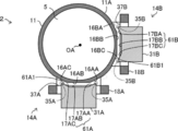
- the first middle yoke 31A has a recess 61A1.
- the side surface 61A of the first middle yoke 31A facing the outer peripheral surface of the lens 5 is an example of a “recess” according to the technique of the present disclosure.
- the side surface 61A is formed as a recess 61A1 by being formed in a concave shape in a direction away from the optical axis OA.
- a part of the outer peripheral surface 11A of the holding frame 11 is composed of three planes 16AA, 16AB, 16AC cut out in a plane.
- the side surface 61A is formed in a concave shape composed of three planes 17AA, 17AB, 17AC, which is complementary to the shape formed by the three planes 16AA, 16AB, 16AC.
- a part of the outer peripheral surface 11A of the holding frame 11 is composed of three planes 16BA, 16BB, and 16BC cut out in a plane.
- the side surface 61B is formed in a concave shape composed of three planes 17BA, 17BB and 17BC, which is complementary to the shape formed by the three planes 16BA, 16BB and 16BC.
- the holding frame 11 moves in the direction of arrow Q, that is, in the direction of the second middle yoke 31B
- the holding frame 11 shown by the solid line moves to the position shown by the dotted line.
- the shape of the second middle yoke 31B is a rectangular parallelepiped
- the holding frame 11 collides with the virtual side surface 62 inside the second middle yoke 31B, so that the movement in the arrow Q direction is restricted.
- the holding frame 11, that is, the lens 5 is separated by a distance x from the case where the second middle yoke 31B is a rectangular parallelepiped. It can be brought close to the second middle yoke 31B. The same can be said for the first VCM14A.
- the side surface 61A of the first middle yoke 31A has two tip portions 35A.
- the two tip portions 35A are both ends of the recess 61A1 in the tangential direction of the outer circumference of the lens 5.
- the two tip portions 35A project from the first coil 18A toward the outer peripheral surface side of the lens 5 at the initial position of the first coil.
- the technique of the present disclosure is limited to this. Not done. Even if the first coil 18A is at a position other than the initial position of the first coil, the two tip portions 35A may protrude from the first coil 18A toward the outer peripheral surface side of the lens 5. Further, although an example in which the tip portion 35A is formed at both ends of the side surface 61A is given here, the technique of the present disclosure is not limited to this. The tip 35A may be formed only at one end of the side surface 61A. In the second embodiment, the two tip portions 35A project from the first coil 18A toward the outer peripheral surface side of the lens 5 even within the movable range of the first coil 18A.
- the side surface 61B of the second middle yoke 31B has two tip portions 35B.
- the two tip portions 35B are both end portions of the recess 61B1 in the tangential direction of the outer circumference of the lens 5.
- the two tip portions 35A project from the second coil 18B toward the outer peripheral surface side of the lens 5 at the initial position of the second coil.
- the two tip portions 35B project from the second coil 18B toward the outer peripheral surface side of the lens 5, but the technique of the present disclosure is limited to this. Not done. Even if the second coil 18B is at a position other than the initial position of the second coil, the two tip portions 35B may protrude from the second coil 18B toward the outer peripheral surface side of the lens 5. Further, although an example in which the tip portion 35B is formed at both ends of the side surface 61B is given here, the technique of the present disclosure is not limited to this. The tip 35B may be formed only at one end of the side surface 61B. In the second embodiment, the two tip portions 35B project from the second coil 18B toward the outer peripheral surface side of the lens 5 even within the movable range of the second coil 18B.
- the lens driving device 2 according to the second embodiment With the configuration of the lens driving device 2 according to the second embodiment described above, the same effect as that of the lens driving device 1 according to the first embodiment can be obtained. Further, the modification applicable to the first embodiment is also applicable to the second embodiment.
- the lens driving device 3 according to the third embodiment will be described with reference to the drawings.
- the elements having the same configuration as the lens driving device 1 of the first embodiment are designated by the same reference numerals and the description thereof will be omitted.
- the lens driving device 3 has a holding frame 12 for holding the lens 5, a first VCM 15A, and a second VCM 15B.
- the first VCM 15A includes a magnet portion 50A for the first VCM and a first coil 18A.
- the first VCM magnet portion 50A includes a first upper yoke 20A, a first upper magnet 25A, a first middle yoke 41A, a first lower magnet 26A, and a first lower yoke 22A.
- the first upper yoke 20A, the first upper magnet 25A, the first lower magnet 26A, the first lower yoke 22A, and the first coil 18A of the first VCM magnet portion 50A are the same as the corresponding elements of the lens driving device 1. Is.
- the second VCM 15B includes a magnet portion 50B for the second VCM and a second coil 18B.
- the second VCM magnet portion 50B includes a second upper yoke 20B, a second upper magnet 25B, a second middle yoke 41B, a second lower magnet 26B, and a second lower yoke 22B.
- the second upper yoke 20B, the second upper magnet 25B, the second lower magnet 26B, the second lower yoke 22B, and the second coil 18B of the second VCM magnet portion 50B are the same as the corresponding elements of the lens driving device 1. Is.
- the first VCM magnet portion 50A and the second VCM magnet portion 50B are fixed to the housing 100.
- the first coil 18A and the second coil 18B are fixed to the holding frame 12.
- the first middle yoke 41A has a recess 71A1.
- the side surface 71A of the first middle yoke 41A facing the outer peripheral surface of the lens 5 is an example of a “recess” according to the technique of the present disclosure.
- the side surface 71A is formed as a recess 71A1.
- the side surface 71A is formed as a recess 71A1 by being formed in a concave shape in a direction away from the optical axis OA.
- the side surface 71A is recessed along the outer peripheral shape of the holding frame 12.
- the outer peripheral surface 12A of the holding frame 12 has a convex portion 73A configured in a stepped shape.
- the side surface 71A is formed as a concave portion 71A1 complementary to the convex portion 73A.
- the second middle yoke 41B has a recess 71B1.
- the side surface 71B of the second middle yoke 41B facing the outer peripheral surface of the lens 5 is an example of a “recess” according to the technique of the present disclosure.
- the side surface 71B is formed as a recess 71B1.
- the side surface 71B is formed as a recess 71B1 by being formed in a concave shape in a direction away from the optical axis OA.
- the side surface 71B is recessed along the outer peripheral shape of the holding frame 12.
- the outer peripheral surface 12A of the holding frame 12 has a convex portion 73B configured in a stepped shape.
- the side surface 71B is formed as a concave portion 71B1 complementary to the convex portion 73B.
- the holding frame 12 moves in the direction of arrow Q, that is, in the direction of the second middle yoke 41B
- the holding frame 12 shown by the solid line moves to the position shown by the dotted line.
- the shape of the second middle yoke 41B is a rectangular parallelepiped
- the holding frame 12 collides with the virtual side surface 72 inside the second middle yoke 41B, so that the movement in the arrow Q direction is restricted.
- the side surface 71B of the second middle yoke 41B according to the third embodiment is formed as the recess 71B1
- the holding frame 12, that is, the lens 5 is separated by a distance x from the case where the second middle yoke 41B is a rectangular parallelepiped. It can be approached to the second middle yoke 41B. The same can be said for the first VCM15A.
- the side surface 71A of the first middle yoke 41A has two tip portions 35A.
- the two protruding ends 35A are both ends of the recess 71A1 in the tangential direction of the outer circumference of the lens 5.
- the two tip portions 35A project from the first coil 18A toward the outer peripheral surface side of the lens 5 at the initial position of the first coil.
- two projecting tip portions 35A project from the first coil 18A toward the outer peripheral surface side of the lens 5 at the initial position of the first coil, but the technique of the present disclosure is limited to this. Not done. Even if the first coil 18A is at a position other than the initial position of the first coil, the two tip portions 35A may protrude from the first coil 18A toward the outer peripheral surface side of the lens 5. Further, although an example in which the tip portion 35A is formed at both ends of the side surface 71A is given here, the technique of the present disclosure is not limited to this. The tip 35A may be formed only at one end of the side surface 71A. In the third embodiment, the two tip portions 35A project from the first coil 18A toward the outer peripheral surface side of the lens 5 even within the movable range of the first coil 18A.
- the side surface 71B of the second middle yoke 41B has two tip portions 35B.
- the two tip portions 35B are both end portions of the recess 71B1 in the tangential direction of the outer circumference of the lens 5.
- the two tip portions 35A project from the second coil 18B toward the outer peripheral surface side of the lens 5 at the initial position of the second coil.
- the two tip portions 35B project from the second coil 18B toward the outer peripheral surface side of the lens 5, but the technique of the present disclosure is limited to this. Not done. Even if the second coil 18B is at a position other than the initial position of the second coil, the two tip portions 35B may protrude from the second coil 18B toward the outer peripheral surface side of the lens 5. Further, although an example in which the tip portion 35B is formed at both ends of the side surface 71B is given here, the technique of the present disclosure is not limited to this. The tip 35B may be formed only at one end of the side surface 71B. In the third embodiment, the two tip portions 35B project from the second coil 18B toward the outer peripheral surface side of the lens 5 even within the movable range of the second coil 18B.
- the lens driving device 3 according to the third embodiment With the configuration of the lens driving device 3 according to the third embodiment described above, the same effect as that of the lens driving device 1 according to the first embodiment can be obtained. Further, the modification applicable to the first embodiment is also applicable to the third embodiment.
- the lens driving device 4 according to the fourth embodiment will be described with reference to the drawings.
- the shapes of the first coil 80A and the second coil 80B are different from the shapes of the first coil 18A and the second coil 18B shown in the first embodiment. ..
- Other configurations are the same as those of the lens driving device 1 described in the first embodiment.
- the first coil 80A and the second coil 80B of the lens driving device 4 are formed by bending along the outer peripheral shape of the holding frame 10.
- at least one end of both ends of the first coil 80A and the second coil 80B in the tangential direction of the outer circumference of the lens 5 is formed by bending along the outer peripheral shape of the holding frame 10. Bending along the outer peripheral shape includes, for example, bending in a direction approaching the optical axis OA.
- both ends of the first coil 80A and the second coil 80B are bent.
- the voice coil motor In order to increase the thrust of the voice coil motor, it is effective to increase the length of the coil in the longitudinal direction. However, when the coil is lengthened, it is necessary to increase the size of the lens driving device so that both ends of the coil do not interfere with the housing.
- the outermost part of the first coil 80A and the second coil 80B is from the center of the lens 5. The distance to can be reduced. Therefore, the diameter of the lens driving device 4 can be reduced.
- the thrust for driving the holding frame 10 can be generated. This is the part that does not contribute. Therefore, even if the lens is bent in the direction closer to the holding frame 10, the thrust of the lens driving device 4 does not decrease as compared with the case where the lens driving device 4 is not bent.
- each coil 82A, 82B has a receiving recess 83 that receives the outer peripheral portion of the holding frame 10X.
- the receiving recess 83 is an example of a “dent” according to the technique of the present disclosure.
- each of the coils 82A and 82B is formed by bending both ends of the outer circumference of the lens 5 in the tangential direction along the outer peripheral shape of the holding frame 10X, as shown in the fourth embodiment. Has been done.
- the outer peripheral surface of the holding frame 10X to which the coils 82A and 82B are attached has a convex portion 85 received by the receiving concave portion 83.
- the receiving recess 83 of each of the coils 82A and 82B is formed in a concave shape that matches the convex portion 85.
- Other configurations are the same as those of the lens driving device 1 described in the first embodiment.
- the receiving recess 83 By providing the receiving recess 83, it becomes easier to attach the coils 82A and 82B to the holding frame 10X as compared with the case where the receiving recess 83 is not provided. Further, as described above, the coils 82A and 82B are arranged at intervals of 90 °, but the holding frames 10X have convex portions 85 arranged at intervals of 90 °, so that the coils 82A and 82B are positioned. Becomes easier. Further, the coils 82A and 82B can be brought into close contact with the holding frame 10X. Therefore, the lens driving device can be made smaller than the case where the receiving recess 83 is not provided.
- the coil is fixed to the holding frame of the lens 5, and the magnet portion is fixed to the housing 100.
- the coil may be fixed to the housing and the magnet portion may be fixed to the holding frame.
- the magnet portion is larger in size and heavier than the coil, it is necessary to increase the thrust of the holding frame when the magnet portion is fixed to the holding frame, and the size of the driving portion is increased. Therefore, it is preferable that the coil is fixed to the holding frame of the lens 5 and the magnet portion is fixed to the housing in terms of miniaturization of the lens driving device.
- the lens driving device can be applied to, for example, an imaging device such as a digital camera and a digital video camera, and an imaging module mounted on an electronic endoscope and a mobile phone with a camera.
- a and / or B is synonymous with "at least one of A and B". That is, “A and / or B” means that it may be only A, only B, or a combination of A and B. Further, in the present specification, when three or more matters are connected by “and / or", the same concept as “A and / or B" is applied.
Landscapes
- Physics & Mathematics (AREA)
- Electromagnetism (AREA)
- General Physics & Mathematics (AREA)
- Optics & Photonics (AREA)
- Engineering & Computer Science (AREA)
- Power Engineering (AREA)
- Adjustment Of Camera Lenses (AREA)
- Lens Barrels (AREA)
- Reciprocating, Oscillating Or Vibrating Motors (AREA)
Priority Applications (2)
| Application Number | Priority Date | Filing Date | Title |
|---|---|---|---|
| JP2021520743A JP7203965B2 (ja) | 2019-05-21 | 2020-05-14 | レンズ駆動装置 |
| US17/455,269 US20220075201A1 (en) | 2019-05-21 | 2021-11-17 | Lens drive device |
Applications Claiming Priority (2)
| Application Number | Priority Date | Filing Date | Title |
|---|---|---|---|
| JP2019095095 | 2019-05-21 | ||
| JP2019-095095 | 2019-05-21 |
Related Child Applications (1)
| Application Number | Title | Priority Date | Filing Date |
|---|---|---|---|
| US17/455,269 Continuation US20220075201A1 (en) | 2019-05-21 | 2021-11-17 | Lens drive device |
Publications (1)
| Publication Number | Publication Date |
|---|---|
| WO2020235439A1 true WO2020235439A1 (ja) | 2020-11-26 |
Family
ID=73459294
Family Applications (1)
| Application Number | Title | Priority Date | Filing Date |
|---|---|---|---|
| PCT/JP2020/019249 Ceased WO2020235439A1 (ja) | 2019-05-21 | 2020-05-14 | レンズ駆動装置 |
Country Status (3)
| Country | Link |
|---|---|
| US (1) | US20220075201A1 (https=) |
| JP (1) | JP7203965B2 (https=) |
| WO (1) | WO2020235439A1 (https=) |
Cited By (2)
| Publication number | Priority date | Publication date | Assignee | Title |
|---|---|---|---|---|
| CN112904641A (zh) * | 2021-05-06 | 2021-06-04 | 新思考电机有限公司 | 抖动补偿装置、照相装置以及电子设备 |
| WO2025104996A1 (ja) * | 2023-11-14 | 2025-05-22 | キヤノン株式会社 | レンズ駆動装置 |
Citations (3)
| Publication number | Priority date | Publication date | Assignee | Title |
|---|---|---|---|---|
| JPH11344739A (ja) * | 1998-06-02 | 1999-12-14 | Tochigi Nikon:Kk | ブレ補正装置及びブレ補正カメラ |
| JP2015011108A (ja) * | 2013-06-27 | 2015-01-19 | キヤノン株式会社 | 像振れ補正装置、レンズ鏡筒、光学機器、および撮像装置 |
| JP2017116663A (ja) * | 2015-12-22 | 2017-06-29 | オリンパス株式会社 | ブレ補正装置 |
Family Cites Families (3)
| Publication number | Priority date | Publication date | Assignee | Title |
|---|---|---|---|---|
| JP2004191453A (ja) * | 2002-12-09 | 2004-07-08 | Sony Corp | レンズ駆動装置および撮像装置 |
| JP5821120B2 (ja) * | 2011-10-07 | 2015-11-24 | 株式会社タムロン | 防振アクチュエータ、及びそれを備えたレンズユニット、カメラ |
| JP2017173756A (ja) * | 2016-03-25 | 2017-09-28 | Hoya株式会社 | 撮像装置 |
-
2020
- 2020-05-14 JP JP2021520743A patent/JP7203965B2/ja active Active
- 2020-05-14 WO PCT/JP2020/019249 patent/WO2020235439A1/ja not_active Ceased
-
2021
- 2021-11-17 US US17/455,269 patent/US20220075201A1/en not_active Abandoned
Patent Citations (3)
| Publication number | Priority date | Publication date | Assignee | Title |
|---|---|---|---|---|
| JPH11344739A (ja) * | 1998-06-02 | 1999-12-14 | Tochigi Nikon:Kk | ブレ補正装置及びブレ補正カメラ |
| JP2015011108A (ja) * | 2013-06-27 | 2015-01-19 | キヤノン株式会社 | 像振れ補正装置、レンズ鏡筒、光学機器、および撮像装置 |
| JP2017116663A (ja) * | 2015-12-22 | 2017-06-29 | オリンパス株式会社 | ブレ補正装置 |
Cited By (3)
| Publication number | Priority date | Publication date | Assignee | Title |
|---|---|---|---|---|
| CN112904641A (zh) * | 2021-05-06 | 2021-06-04 | 新思考电机有限公司 | 抖动补偿装置、照相装置以及电子设备 |
| CN112904641B (zh) * | 2021-05-06 | 2021-08-13 | 新思考电机有限公司 | 抖动补偿装置、照相装置以及电子设备 |
| WO2025104996A1 (ja) * | 2023-11-14 | 2025-05-22 | キヤノン株式会社 | レンズ駆動装置 |
Also Published As
| Publication number | Publication date |
|---|---|
| US20220075201A1 (en) | 2022-03-10 |
| JPWO2020235439A1 (https=) | 2020-11-26 |
| JP7203965B2 (ja) | 2023-01-13 |
Similar Documents
| Publication | Publication Date | Title |
|---|---|---|
| KR102002718B1 (ko) | 회전식 볼-가이드 음성 코일 모터 | |
| CN104820272B (zh) | 透镜驱动装置、自动对焦相机及带照相机的移动终端装置 | |
| US9897774B2 (en) | Lens unit and imaging device | |
| JP2018010295A (ja) | レンズ駆動モジュール | |
| KR20150113675A (ko) | 듀얼 카메라 모듈 | |
| KR102432247B1 (ko) | 카메라 액추에이터 및 이를 포함하는 광 굴절식 카메라 모듈 | |
| WO2010067550A1 (ja) | レンズ駆動装置 | |
| JP5899089B2 (ja) | 光学装置及びこれを備える撮像装置 | |
| EP4024841B1 (en) | Photographing module and mobile terminal | |
| CN114721119A (zh) | 光学元件驱动机构 | |
| WO2020235439A1 (ja) | レンズ駆動装置 | |
| JP6099924B2 (ja) | 光学機器およびそれを備えた撮像装置 | |
| JP2017146571A (ja) | 振れ補正機能付き光学ユニット | |
| US12489977B2 (en) | Camera module | |
| WO2011034001A1 (ja) | レンズ駆動装置 | |
| WO2013073190A1 (ja) | レンズ鏡筒 | |
| JP5245256B2 (ja) | カメラ | |
| JP5378887B2 (ja) | レンズ駆動装置 | |
| JP5817265B2 (ja) | 光学装置及びカメラ | |
| JP2010191143A (ja) | レンズ駆動装置 | |
| CN117908247A (zh) | 一种混合磁阻力直驱精密偏摆镜及方法 | |
| KR20220074675A (ko) | 카메라 액추에이터 및 이를 포함하는 광 굴절식 카메라 모듈 | |
| JP2014228625A (ja) | ブレ補正装置、レンズ鏡筒および撮影装置 | |
| CN116802536A (zh) | 音圈马达和镜头镜筒 | |
| CN221782500U (zh) | 透镜驱动装置和相机模块 |
Legal Events
| Date | Code | Title | Description |
|---|---|---|---|
| 121 | Ep: the epo has been informed by wipo that ep was designated in this application |
Ref document number: 20808280 Country of ref document: EP Kind code of ref document: A1 |
|
| ENP | Entry into the national phase |
Ref document number: 2021520743 Country of ref document: JP Kind code of ref document: A |
|
| NENP | Non-entry into the national phase |
Ref country code: DE |
|
| 122 | Ep: pct application non-entry in european phase |
Ref document number: 20808280 Country of ref document: EP Kind code of ref document: A1 |