WO2020235400A1 - Dispositif de traitement d'image, procédé de traitement d'image et programme - Google Patents
Dispositif de traitement d'image, procédé de traitement d'image et programme Download PDFInfo
- Publication number
- WO2020235400A1 WO2020235400A1 PCT/JP2020/019019 JP2020019019W WO2020235400A1 WO 2020235400 A1 WO2020235400 A1 WO 2020235400A1 JP 2020019019 W JP2020019019 W JP 2020019019W WO 2020235400 A1 WO2020235400 A1 WO 2020235400A1
- Authority
- WO
- WIPO (PCT)
- Prior art keywords
- image
- pattern
- output
- correction
- viewing
- Prior art date
Links
Images


Classifications
-
- H—ELECTRICITY
- H04—ELECTRIC COMMUNICATION TECHNIQUE
- H04N—PICTORIAL COMMUNICATION, e.g. TELEVISION
- H04N9/00—Details of colour television systems
- H04N9/12—Picture reproducers
- H04N9/31—Projection devices for colour picture display, e.g. using electronic spatial light modulators [ESLM]
-
- H—ELECTRICITY
- H04—ELECTRIC COMMUNICATION TECHNIQUE
- H04N—PICTORIAL COMMUNICATION, e.g. TELEVISION
- H04N9/00—Details of colour television systems
- H04N9/12—Picture reproducers
- H04N9/31—Projection devices for colour picture display, e.g. using electronic spatial light modulators [ESLM]
- H04N9/3179—Video signal processing therefor
- H04N9/3185—Geometric adjustment, e.g. keystone or convergence
-
- H—ELECTRICITY
- H04—ELECTRIC COMMUNICATION TECHNIQUE
- H04N—PICTORIAL COMMUNICATION, e.g. TELEVISION
- H04N5/00—Details of television systems
- H04N5/74—Projection arrangements for image reproduction, e.g. using eidophor
-
- H—ELECTRICITY
- H04—ELECTRIC COMMUNICATION TECHNIQUE
- H04N—PICTORIAL COMMUNICATION, e.g. TELEVISION
- H04N9/00—Details of colour television systems
- H04N9/12—Picture reproducers
- H04N9/31—Projection devices for colour picture display, e.g. using electronic spatial light modulators [ESLM]
- H04N9/3102—Projection devices for colour picture display, e.g. using electronic spatial light modulators [ESLM] using two-dimensional electronic spatial light modulators
- H04N9/312—Driving therefor
- H04N9/3123—Driving therefor using pulse width modulation
-
- H—ELECTRICITY
- H04—ELECTRIC COMMUNICATION TECHNIQUE
- H04N—PICTORIAL COMMUNICATION, e.g. TELEVISION
- H04N9/00—Details of colour television systems
- H04N9/12—Picture reproducers
- H04N9/31—Projection devices for colour picture display, e.g. using electronic spatial light modulators [ESLM]
- H04N9/3191—Testing thereof
- H04N9/3194—Testing thereof including sensor feedback
Definitions
- the present disclosure relates to an image processing apparatus, an image processing method, and a program. More specifically, the present invention relates to an image processing apparatus for performing correction of a projected image by a projector, an image processing method, and a program.
- the image When projecting an image on the screen using a projector, if the projector cannot be placed in front of the screen, the image may be projected diagonally to the right or diagonally to the left of the screen. However, when the image is projected from an oblique direction, the image on the screen becomes a distorted image. By executing a correction process for eliminating such image distortion inside the projector and projecting the image, it is possible to display an image without distortion.
- Patent Document 1 International Publication WO2017 / 104447
- a predetermined pattern image for calculating correction parameters is projected on a screen, a pattern image displayed on the screen is photographed by a camera, and a distortion mode is analyzed using the photographed pattern image, and the analysis result is obtained.
- the display of the viewing image is temporarily stopped and the pattern is displayed again. It is necessary to perform processing such as displaying an image and taking a picture with a camera, calculating a new correction parameter based on the shot pattern image, and applying the parameter to perform image correction. During this time, the display of the viewing image has to be interrupted. Such interruption of the viewing image is troublesome for the viewer who views the viewing image.
- the present disclosure has been made in view of the above problems, for example, by calculating the parameters of distortion correction of the projected image by the projector without interrupting the presentation of the viewing image to the viewer, and the image based on the calculated parameters. It is an object of the present invention to provide an image processing apparatus capable of performing correction, an image processing method, and a program.
- the first aspect of the disclosure is An image projection unit that executes image projection processing by the pulse width modulation (PWM) method, and An output image control unit that sets a part of the one-frame output period of the viewing image as the output period of the pattern image used to calculate the image correction parameters.
- a correction parameter calculation unit that calculates image correction parameters using a shooting pattern image taken by a camera during the output period of the pattern image, and a correction parameter calculation unit.
- the image processing apparatus has an image correction unit that executes correction processing of the viewing image by using the image correction parameter calculated by the correction parameter calculation unit.
- the second aspect of the present disclosure is This is an image processing method executed in an image processing device.
- the image processing apparatus has an image projection unit that executes image projection processing by a pulse width modulation (PWM) method.
- the output image control unit An output image control step that sets a part of the one-frame output period of the viewing image as the output period of the pattern image used to calculate the image correction parameters, and A correction parameter calculation step in which the correction parameter calculation unit calculates an image correction parameter using a shooting pattern image taken by a camera during the output period of the pattern image.
- the image correction unit executes an image correction step of executing the correction processing of the viewing image by using the image correction parameter calculated by the correction parameter calculation unit.
- the third aspect of the present disclosure is A program that executes image processing in an image processing device.
- the image processing apparatus has an image projection unit that executes image projection processing by a pulse width modulation (PWM) method.
- PWM pulse width modulation
- the program An output image control step that causes the output image control unit to set a part of the one-frame output period of the viewing image as the output period of the pattern image used for calculating the image correction parameter.
- the program of the present disclosure is, for example, a program that can be provided by a storage medium or a communication medium that is provided in a computer-readable format to an information processing device or a computer system that can execute various program codes.
- a program that can be provided by a storage medium or a communication medium that is provided in a computer-readable format to an information processing device or a computer system that can execute various program codes.
- system is a logical set configuration of a plurality of devices, and the devices having each configuration are not limited to those in the same housing.
- a device and a method of capturing a pattern image, calculating correction parameters, and performing image correction are realized without interrupting the presentation of the viewing image projected by the projector.
- an image projection unit that executes image projection processing by a pulse width modulation (PWM) method, and a pattern image output that uses a part of the one-frame output period of the viewing image for calculating image correction parameters.
- PWM pulse width modulation
- the output image control unit controls, for example, the pattern image output period so that the pixel value of the pattern image is in the range from the lowest pixel value of the viewing image to less than the lowest significant pixel value.
- FIG. 1 shows an example of a projected image by a projector, which is an example of the image processing apparatus of the present disclosure.
- FIG. 1A is an example in which an image processing device (projector) 100 is arranged at a position in front of the screen 10 and an image is projected and displayed on the screen 10. In this case, the projected image is not distorted.
- projector image processing device
- FIG. 1B is an example in which the projected image of the image processing device (projector) 100 is displayed from an oblique direction with respect to the screen 10.
- the projected image is distorted.
- image distortion can be corrected by applying geometric correction such as keystone correction to the projection image.
- a distortion-free image can be projected and displayed on the screen 10 by performing correction processing on the projection image and projecting the corrected image in the image processing device (projector) 100. That is, as shown in FIG. 2C, even if the projected image of the image processing device (projector) 100 is displayed from an oblique direction with respect to the screen 10, it is possible to display an image without distortion.
- This correction process can be performed manually by the operator who operates the projector, but it requires complicated work and is difficult for an inexperienced user.
- a process of projecting a specific pattern image, shooting the projected pattern image with a camera, and calculating the correction parameter from the shot pattern image is known.
- a pattern image 20 as shown in FIG. 3 is displayed, the pattern image is photographed by a camera, and the photographed image is analyzed to calculate a parameter (correction parameter) required for distortion correction.
- the correction parameter calculation process by projecting such a pattern image is a known technique described in, for example, Patent Document 1 (International Publication WO2017 / 104447) described above.
- the display of the viewing image is temporarily stopped and the pattern is displayed again. It is necessary to perform processing such as displaying an image and taking a picture with a camera, calculating a new correction parameter based on the shot pattern image, and applying the parameter to perform image correction. During this time, the display of the viewing image has to be interrupted. Such interruption of the viewing image is troublesome for the viewer who views the viewing image.
- the present disclosure makes it possible to calculate the distortion correction parameters of the projected image by the projector and perform the image correction by the calculated parameters without interrupting the presentation of the viewing image to the viewer.
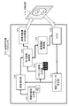
- FIG. 4 is a diagram showing a configuration example of the image processing device (projector) 100 of the present disclosure.
- the image processing device 100 includes a viewing image output unit 101, an image correction unit 102, an output image control unit 103, an image projection unit 104, a pattern image output unit 105, a camera 106, and a correction parameter calculation unit 107.
- the viewing image output unit 101 outputs a viewing image, for example, an image of a movie or the like.
- a viewing image for example, an image stored in a storage unit (not shown), or video data such as a movie input from an external server or the like via an external playback device or communication unit can be used.
- the image correction unit 102 corrects an image input from the viewing image output unit 101. That is, correction processing such as geometric correction is performed to enable distortion-free image display. Image correction processing is performed to enable projection of a distortion-free image as described with reference to FIG.
- the correction parameter applied to this correction process is input from the correction parameter calculation unit 107.
- the output image control unit 103 selects either the viewing image corrected by the image correction unit 102 or the pattern image output from the pattern image output unit 105 as an output image and outputs it to the image projection unit 104.
- the image projection unit 104 projects either a corrected viewing image or a pattern image selected by the output image control unit 103. For example, the projected image 110 shown in the figure is displayed on the screen.
- the image projection unit 104 projects an image by a pulse width modulation (PWM) method.
- PWM pulse width modulation
- the PWM method is an image output method that expresses the brightness and color of each pixel by controlling the output time of each pixel for each frame constituting the image. The details of this PWM method will be described later.
- the pattern image output unit 105 outputs a pattern image for calculating the correction parameters applied to the distortion correction of the viewing image to the output image control unit 103.
- the pattern image is, for example, the pattern image 20 described above with reference to FIG.
- the camera 106 takes an image at the timing when the pattern image is projected through the image projection unit 104.
- the image shooting control unit 108 executes the timing control of the image shooting.
- the projection pattern image taken by the camera 106 is output to the correction parameter calculation unit 107.
- the correction parameter calculation unit 107 analyzes the projection pattern image captured by the camera 106 and calculates the parameters (correction parameters) required for distortion correction. Since this correction parameter calculation process is a known process described in, for example, Patent Document 1 (International Publication WO2017 / 104447), detailed description thereof will be omitted.
- the image shooting control unit 108 controls the shooting timing of the projected image by the camera 106.
- the image shooting control unit 108 inputs pattern image output timing information from the output image control unit 103, and causes the camera 106 to perform image shooting at this timing. By this process, the camera 106 can take a projected image of the pattern image.
- the image projection unit 104 of the image processing device (projector) 100 shown in FIG. 4 performs image projection by a pulse width modulation (PWM) method.
- the PWM method is an image output method that expresses the brightness and color of each pixel by controlling the output time of each pixel for each frame constituting the image.
- FIG. 5 shows (A) Vertical sync signal (Vsync) (B) Pixel unit PWM output Each of these data is shown.
- the two pulse intervals of the vertical synchronization signal (Vsync) correspond to the output period of one frame of the image.
- the pixel with the highest brightness (255) is set to the output (light emission) state (ON) for the entire period of one frame period.
- the pixel with the lowest brightness (0) is in the output (light emission) stop state (OFF) for the entire period of one frame period.
- the pixels having the intermediate brightness (128) are set to the output (light emission) state (ON) for the first half of the one frame period. Only the (1/2 frame) shown in the figure is set to the output (light emission) state (ON). Further, a pixel having a brightness level of 1/4 (64) is set to an output (light emission) state (ON) for a quarter period of one frame period. Only the (1/4 frame) shown in the figure is set to the output (light emission) state (ON).
- the luminance value of each pixel can be expressed by the gradation of 0 to 255. It will be possible. That is, a grayscale image can be displayed as a projected image.
- FIG. 6 is a diagram showing an output (light emission) period control example corresponding to each gradation of gradations 0 to 255. In this way, it is possible to control the brightness value of each pixel by controlling the output (light emission) period within one frame period for each pixel.
- the image projection unit 104 of the image processing apparatus 100 of the present disclosure performs image projection by a pulse width modulation (PWM) method. By this process, grayscale image projection can be performed.
- PWM pulse width modulation
- a color image can be output by projecting an image for each RGB output by a pulse width modulation (PWM) method.
- PWM pulse width modulation
- the image projection unit 104 of the image processing apparatus 100 of the present disclosure can also project a color image by a pulse width modulation (PWM) method.
- the image processing device 100 of the present disclosure enables calculation of correction parameters based on the pattern image and correction of the viewing image without interrupting the presentation of the viewing image to the viewer. is there.
- details of the pattern image projection and the correction processing of the viewing image executed by the image processing apparatus 100 of the present disclosure will be described.
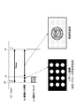
- FIG. 7 shows an example of an image projected by the image processing apparatus 100 of the present disclosure.
- FIG. 7 shows an example of each of the following images. (1) Viewing image (2) Pattern image
- the viewing image is, for example, an image for viewing a movie or the like.
- the pattern image is an image projected to calculate the correction parameters applied to the correction process for displaying the viewing image as a normal image without distortion.
- the "(2) pattern image” shown in the figure is an example.
- the "(2) pattern image” shown in the figure is a pattern image in which dots are arranged in a grid pattern, that is, dots are arranged at intersections of a grid composed of horizontal and vertical lines.
- a pattern image for calculating correction parameters Not limited to such a pattern image, various images can be used. A plurality of specific examples of other pattern images will be described later.
- the image processing device (projector) 100 of the present disclosure projects, for example, a pattern image in which the dots shown in the figure are arranged at the intersections of a grid composed of horizontal lines and vertical lines, and is photographed by the camera 106.
- the image processing device (projector) 100 does not face the screen, the dots of the pattern image captured by the camera are displayed deviated from the intersection position of the grid composed of the horizontal lines and the vertical lines.
- the correction parameter calculation unit 107 analyzes the arrangement of each dot in the pattern image captured by the camera 106. This analysis makes it possible to analyze, for example, the position on which each of the constituent pixels of the projected image is displayed on the screen. Using this analysis result, a correction parameter for eliminating the distortion of the display image on the screen is calculated.
- the correction parameter calculated by the correction parameter calculation unit 107 is input to the image correction unit 102, and the image correction unit 102 applies this correction parameter to execute correction processing such as geometric transformation of the viewing image.
- correction processing it is possible to project the viewing image as a distortion-free image as in the state where the image processing device (projector) 100 faces the screen.
- the image processing device 100 of the present disclosure does not interrupt the presentation of the viewing image to the viewer.
- A Pattern image display processing
- B Camera shooting process of pattern image
- C Correction parameter calculation process
- D Image correction processing for viewing
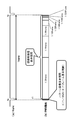
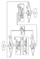
- FIG. 8 shows each of the following data as time series data.
- A Vertical sync signal (Vsync)
- B Image output period
- c Shooting timing
- the two pulse intervals of the vertical synchronization signal (Vsync) correspond to the output period of one frame of the image. Let the time tx to ty be the output period of one image frame.
- time tx to ty two images, a pattern image and a viewing image, are output (projected) by dividing the time.
- the time tx to t1 is defined as the pattern image output period
- the subsequent time t1 to ty is defined as the viewing image display period.
- This display switching control is executed by the output image control unit 103 of the image processing device 100 shown in FIG.
- the pattern image output period (tx to t1) is shown long for the sake of clarity in the figure, but for example, it is several hundredths of the one-frame output period (tx to ty), specifically, for example, 1 /. It is a very short time of about 300.
- the shooting timing is the shooting timing of the camera 106 that shoots the projected image.
- the shooting timing is set between the times tx and t1.
- the entire section of time tx to t1 is shown as the shooting timing, but the projected image may be shot at any timing within this period.
- the control of the image capturing timing is executed by the image capturing control unit 108.
- the image shooting control unit 108 inputs the pattern image output timing information from the output image control unit 103, and causes the camera 106 to perform image shooting at this timing. By this process, the camera 106 can take a projected image of the pattern image.
- the image shooting control unit 108 is between the pattern image display start time (tx) and the pattern image display end time (t1). The shooting start timing of the camera 106 is controlled so that the shooting is completed.
- the image processing apparatus 100 of the present disclosure has two images, that is, two images during the display period of one frame.
- Pattern image display period: tx to t1
- Viewing image display period: t1 to ty
- the output image control unit 103 of the image processing apparatus 100 of the present disclosure sets the pattern image output period (tx to t1) to be a very short time, for example, about 1/300 of the one frame output period (tx to ty). To control.
- the pattern image output period (tx to t1) is set to one frame output period (tx).
- the time is 1/256 or less of ⁇ ty).
- the output image control unit 103 sets the pattern so that the pixel values of the constituent pixels of the pattern image are set in the range from the minimum pixel value (0) to the minimum significant pixel value (1) of the viewing image. Controls the image output period.
- the pattern image displayed during this period is an image composed of pixel values equal to or less than the minimum significant pixel value (1) of the normal image, and the possibility of being detected by the viewer is extremely low. .. That is, the pattern image is an almost invisible image that is not noticed by the viewer.
- the pattern image projected and displayed during the time tx to t1 is captured by the camera 106, and the captured projection pattern image is output to the correction parameter calculation unit 107.
- the correction parameter calculation unit 107 analyzes the projection pattern image captured by the camera 106 and calculates the parameters (correction parameters) required for distortion correction.
- the correction parameters calculated by the correction parameter calculation unit 107 are input to the image correction unit 102.
- the image correction unit 102 applies the correction parameters calculated by the correction parameter calculation unit 107 to perform correction processing for the image input from the viewing image output unit 101. That is, correction processing such as geometric correction is performed to make the projected image a normal image without distortion.
- the image after this correction process is projected from the image projection unit 104 via the output image control unit 103.
- processing that does not stop the display of the viewing image is realized. That is, the image processing device 100 of the present disclosure does not interrupt the presentation of the viewing image to the viewer.
- D) Image correction processing for viewing It is possible to execute these series of processes.
- the frame for displaying the pattern image may be the entire display frame of the viewing image, or may be a part of the viewing image display frame. For example, only one frame may be set as the pattern image display frame every several tens of seconds to several minutes, and the pattern image may not be displayed in the other frames, and only the normal viewing image may be displayed.
- the pattern image output period (tx to t1) is set to, for example, 1/256 or less of the one-frame output period (tx to ty). Was there. This time may not always be sufficient for camera shooting.
- FIG. 10 is a diagram illustrating a process of generating a composite image to be displayed in an image display period other than the pattern image display period during the one-frame display period (tx to ty).
- the composite image is an image generated according to the following (Equation 1).
- Composite image (viewing image)-(((pattern image display period) / (viewing image display period)) x (pattern image)) ... (Equation 1)
- the viewing image display period is a one-frame display period.
- the pattern image display period is a pattern image display period set within one frame period.
- the composite image calculated by the above (Equation 1) is an image obtained by subtracting the value obtained by multiplying the pattern image by the ratio of the 1-frame image display period and the pattern display period from the viewing image.
- the pattern image is, for example, an image expressed at a level from 0 to 255.
- the composite image is a composite image in which the integrated pixel value of the pattern image and the composite image output in one frame output period of the viewing image is set to be substantially equal to the pixel value of the viewing image.
- each of the following data is shown as time-series data in the same manner as described above with reference to FIG.
- the two pulse intervals of the vertical synchronization signal (Vsync) correspond to the output period of one frame of the image. Let the time tx to ty be the output period of one image frame.
- the visual recognition image By switching and displaying these two images within one frame period, the image observed by the viewer, that is, the visual recognition image becomes an image substantially equal to the viewing image as shown in the figure.
- the visual recognition image corresponds to an image calculated by the following calculation formula (Equation 2).
- Visual recognition image (pattern image) x ((pattern image display period) / (viewing image display period)) + (composite image) x (((viewing image display period)-(pattern image display period)) / ( Image display period for viewing)))) ⁇ ⁇ ⁇ (Equation 2)
- the period of the pattern image display period (tx to t2) can be set to various periods. That is, the pattern image display period can be set to be long, and the camera shooting time can be lengthened.
- the shooting timing is the shooting timing of the camera 106 that shoots the projected image.
- the shooting timing is set between the times tx and t2.
- the control of the image capturing timing is executed by the image capturing control unit 108.
- a composite image calculated according to (Equation 1) described with reference to FIG. 10 is generated, and the pattern image and the composite image are switched and displayed within one frame display period to display the pattern image.
- the period of the period (tx to t2) can be set to various periods. That is, the pattern image display period can be set to be long, and the camera shooting time can be lengthened.
- the camera 106 of the image processing device 100 shown in FIG. 4 captures an image within the projection period of the pattern image.
- the captured image of the camera 106 also includes an image around the projected pattern image.
- the captured image includes the screen and various objects around the screen.
- the correction parameter calculation unit 107 needs to perform signal processing for removing an image unrelated to the pattern from the captured image in which such various objects are reflected from the image to be analyzed. This signal processing takes more time as the number of non-analyzed image areas other than the pattern image included in the captured image increases.
- the embodiment described below has a configuration in which such an image region not to be analyzed can be easily removed.
- the removal process of the image region not to be analyzed and the subsequent correction parameter calculation process by pattern analysis are executed by the correction parameter calculation unit 107.
- each of the following data is shown as time series data.
- the two pulse intervals of the vertical synchronization signal (Vsync) correspond to the output period of one frame of the image. Let the time tx to ty be the output period of one image frame. The figure shows the output periods (tx to ty, ty to tz) of two consecutive frames.
- the pattern image a is output within one preceding image frame output period (tx to ty). Further, the pattern image b is output within the next image frame output period (ty to tz). The pattern image b is an inverted image of the pattern image.
- the camera 106 takes an image within the pattern image output period of each frame. As a result, the photographed image a and the photographed image b shown in the lower part of FIG. 12 are photographed. Not only the pattern image but also various surrounding objects are reflected in each photographed image.
- the correction parameter calculation unit 107 inputs the captured images a and b corresponding to these two continuous frames.
- the correction parameter calculation unit 107 calculates an analysis image from the captured images a and b corresponding to these two continuous frames according to the following equation (Equation 3).
- Image for analysis (photographed image a)-(photographed image b) ... (Equation 3)
- Equation 3 is an equation for calculating the difference between (captured image a) and (captured image b) and calculating this difference image as an analysis image.
- This difference calculation process all the same pixel values included in (captured image a) and (captured image b) are canceled. That is, the stationary subject is not included in the difference image (analysis image), and only the pattern of the pattern image remains.
- the correction parameter calculation unit 107 uses this analysis image to execute a correction parameter calculation process applied to the distortion correction. By performing such processing, it is possible to reduce the time required for the detection and exclusion processing of the non-analysis target image area other than the pattern image included in the captured image, and the processing speed can be increased.
- the examples described below are examples in the case where a rolling shutter camera is used as the camera 106 of the image processing apparatus 100 shown in FIG.
- the rolling shutter camera (Rolling Shutter Camera) has a configuration in which exposure is sequentially performed downward from the uppermost line of the image captured by the camera, and the exposure timing differs depending on the vertical position of the imaging pixel.
- each of the following data is shown as time series data.
- the two pulse intervals of the vertical synchronization signal (Vsync) correspond to the output period of one frame of the image.
- the time tx to ty be the output period of one image frame.
- two images, a pattern image and a viewing image are output (projected) by dividing the time.
- the time tx to t1 is defined as the pattern image output period
- the subsequent time t1 to ty is defined as the viewing image display period.
- This display switching control is executed by the output image control unit 103 of the image processing device 100 shown in FIG.
- the shooting timing is the shooting timing of the camera 106 that shoots the projected image.
- the camera 106 is a rolling shutter camera (Rolling Shutter Camera), and has a configuration in which exposure is sequentially performed downward from the top line of the image, depending on the vertical position of the shooting pixel. The exposure timing is different.
- the captured image of the camera becomes an image similar to the captured image shown in the figure.
- the pattern image is captured only in the middle region of the image whose exposure period matches the pattern image display period of time tx to t1, and the pattern image is not captured and the viewing image is captured in the other upper and lower regions. There is.
- the image shooting control unit 108 acquires the output timing information of the pattern image from the output image control unit 103 and executes the control of the shooting start timing in each frame.
- the correction parameter calculation unit 107 synthesizes a plurality of captured images a to c shown in FIG. 14 to generate an analysis image, and executes a correction parameter calculation process using the analysis image.
- pattern image to be applied to the correction parameter calculation an example using a pattern image in which dots are arranged in a grid pattern, that is, dots are arranged at intersections of a grid composed of horizontal lines and vertical lines has been described.
- the pattern image for calculating the correction parameter is not limited to such a pattern image, and various images can be used.
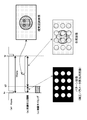
- Pattern image example 1 is a pattern image in which marks are arranged at four corners of the image.
- the deformation (distortion) of the image is a deformation mode that can be expressed by the affine conversion, correction is possible if the positions of the four corners of the image are known, and this FIG. 15 (1) pattern image example 1
- the pattern image shown in is available. Since the pattern image shown in the pattern image example 1 has few detection points, the processing is reduced.
- Pattern image example 2 is a pattern image having two rectangular areas, a peripheral area and an internal area of the pattern image. This pattern image is intended to detect four sides forming a rectangle (quadrangle), and is an example of an effective pattern image when correction is performed so as to match the image with the edge of the screen, for example.
- Pattern image example 3 is an example of using a plurality of patterns having different dot densities.
- the pattern image example 3a is composed of low-density dots
- the pattern image example 3b is composed of high-density dots.
- the pattern image of the pattern image example 3a composed of dots having low density is applied to calculate the correction parameter corresponding to the entire image.
- the deformation area of the projected image is a deformation of a part of the image, that is, a local deformation
- the pattern image of the pattern image example 3b composed of dense dots is applied to correspond to the part of the image area. Calculate the correction parameters.
- FIG. 17 (4) pattern image example 4 is a pattern image in which dots having different brightness or different colors are arranged.
- FIG. 17 (5) pattern image example 5 is a pattern image in which dots having different shapes are arranged. Similar to the above (4) pattern image example 4, it is possible to easily determine the positional relationship of each dot in the pattern image in which dots having different shapes are arranged in this way, and the correction parameter calculation process is efficiently executed. It becomes possible.
- FIG. 13 By using a pattern image in which the positional relationship of each dot can be easily identified as in the pattern image examples 4 and 5 shown in 17, it is possible to execute the composition processing of a plurality of images with high accuracy and in a short time without fail. It will be possible.
- FIG. 18 is a diagram showing a flowchart illustrating a sequence of processes executed by the image processing apparatus 100 of the present disclosure.
- the process according to the flow shown in FIG. 18 is executed under the control of a control unit such as a CPU having a program execution function according to a program stored in the storage unit of the image processing device 100, for example.
- a control unit such as a CPU having a program execution function according to a program stored in the storage unit of the image processing device 100, for example.
- the processing of each step of the flow shown in FIG. 18 will be sequentially described.
- Step S101 the image processing device 100 determines in step S101 whether or not it is the output timing of the pattern image.
- the output timing of the pattern image is predetermined. For example, as described above with reference to FIGS. 6 and 7, at the start timing of one image frame, the pattern image output period is, for example, 1/256 or less of the one frame output period.
- step S101 the output image control unit 103 shown in FIG. 4 determines whether or not it is the output timing of the pattern image.
- the frame for displaying the pattern image may be the entire display frame of the viewing image, or may be a part of the display frame of the viewing image. For example, only one frame may be set as the pattern image display frame every several tens of seconds to several minutes, and the pattern image may not be displayed in the other frames, and only the normal viewing image may be displayed.
- the output image control unit 103 determines that it is the frame start timing of the pattern image display frame defined in advance, the output image control unit 103 proceeds to step S102.
- Step S102 When it is determined in step S101 that it is the frame start timing of the pattern image display frame defined in advance, the output image control unit 103 shown in FIG. 4 inputs a pattern image from the pattern image output unit 105 in step S102. It is output via the image projection unit 104.
- the camera 106 executes the pattern image shooting process.
- the image shooting control process of the camera 106 is executed by the image shooting control unit 108.
- the image shooting control unit 108 inputs the pattern image output timing information from the output image control unit 103, and causes the camera 106 to perform image shooting at this timing. By this process, the camera 106 can take a projected image of the pattern image.
- Step S103 Next, in step S103, a parameter (correction parameter) required for distortion correction of the projected image is calculated using the pattern image captured by the camera 106. This process is a process executed by the correction parameter calculation unit 107.
- the correction parameter calculation unit 107 analyzes the projection pattern image captured by the camera 106 and calculates the parameters (correction parameters) required for distortion correction.
- the correction parameter calculation unit 107 analyzes, for example, the arrangement of dots in the pattern image captured by the camera 106. This analysis makes it possible to analyze, for example, the position on which each of the constituent pixels of the projected image is displayed on the screen. Using this analysis result, a correction parameter for eliminating the distortion of the display image on the screen is calculated.
- the correction parameters calculated by the correction parameter calculation unit 107 are input to the image correction unit 102.
- step S104 the correction process of the viewing image using the correction parameter calculated by the correction parameter calculation unit 107 in step S103 is executed.
- This process is a process executed by the image correction unit 102.
- the image correction unit 102 applies the correction parameters calculated by the correction parameter calculation unit 107 to execute correction processing such as geometric transformation of the viewing image.
- correction processing it is possible to project the viewing image as a distortion-free image as in the state where the image processing device (projector) 100 faces the screen.
- step S105 it is determined whether or not the projection process of the viewing image is completed. If it is not completed, the process of step S101 and subsequent steps is repeated.
- This iterative processing for example, even if the orientation of the image processing device (projector) 100 changes during image projection, new correction parameters are calculated according to the orientation of the image processing device (projector) 100 after the change. , The image correction process to which the calculated correction parameters are applied is executed, and it becomes possible to continuously display the viewing image without distortion. If it is determined in step S105 that the projection process of the viewing image is completed, the process is terminated.
- the image processing apparatus 100 of the present disclosure executes processing in a sequence according to the flow shown in FIG. By executing the processing according to the sequence according to this flow, the image processing apparatus 100 of the present disclosure does not interrupt the presentation of the viewing image to the viewer.
- A Pattern image display processing
- B Camera shooting process of pattern image
- C Correction parameter calculation process
- D Image correction processing for viewing
- the sequence described with reference to FIG. 18 is a basic processing sequence of processing executed by the image processing apparatus 100 of the present disclosure.
- Steps S201 to S203 The processes of steps S201 to S203 are the same as the processes of steps S101 to S103 of the flow described above with reference to FIG.
- the image processing device 100 determines in step S201 whether or not it is the output timing of the pattern image.
- the output image control unit 103 determines that it is the frame start timing of the pattern image display frame defined in advance, the output image control unit 103 proceeds to step S202.
- step S202 the output image control unit 103 inputs a pattern image from the pattern image output unit 105 and outputs it via the image projection unit 104. Further, at this pattern image output timing, the camera 106 executes the pattern image shooting process.
- step S203 the pattern image captured by the camera 106 is used to execute a calculation process of parameters (correction parameters) required for distortion correction of the projected image.
- This process is a process executed by the correction parameter calculation unit 107.
- the correction parameter calculation unit 107 analyzes the projection pattern image captured by the camera 106 and calculates the parameters (correction parameters) required for distortion correction. However, the correction parameter may not be calculated depending on the distortion mode of the image distortion.
- Step S204 it is determined whether or not the calculation of the correction parameter in step S203 was successful. This process is also a process executed by the correction parameter calculation unit 107.
- step S205 If it is determined that the calculation of the correction parameter is successful, the process proceeds to step S205. On the other hand, if it is determined that the calculation of the correction parameter has failed, the process proceeds to step S211.
- Step S211 If it is determined in step S204 that the calculation of the correction parameter has failed, the process proceeds to step S211.
- step S211 the pattern image is changed. This process is executed by the pattern image output unit 105.
- the correction parameter calculation unit 107 determines that the calculation of the correction parameter has failed, it outputs control information (command) for changing the pattern image to be output to the pattern image output unit 105.
- the pattern image output unit 105 changes the pattern image to be output in response to the input of control information (command) from the correction parameter calculation unit 107.
- step S204 the process returns to step S201, and the processes of steps S201 to S204 are executed using the changed pattern image. If it is finally determined in step S204 that the calculation of the correction parameter is successful, the process proceeds to step S205.
- step S205 correction processing of the viewing image using the correction parameter calculated by the correction parameter calculation unit 107 in step S203 is executed.
- This process is a process executed by the image correction unit 102.
- the image correction unit 102 applies the correction parameters calculated by the correction parameter calculation unit 107 to execute correction processing such as geometric transformation of the viewing image.
- correction processing it is possible to project the viewing image as a distortion-free image as in the state where the image processing device (projector) 100 faces the screen.
- step S206 it is determined whether or not the projection process of the viewing image is completed. If it is not completed, the process of step S201 and subsequent steps is repeated.
- This iterative processing for example, even if the orientation of the image processing device (projector) 100 changes during image projection, new correction parameters are calculated according to the orientation of the image processing device (projector) 100 after the change. , The image correction process to which the calculated correction parameters are applied is executed, and it becomes possible to continuously display the viewing image without distortion. If it is determined in step S206 that the projection process of the viewing image is completed, the process is terminated.
- the image processing device 100 of the present disclosure does not interrupt the presentation of the viewing image to the viewer.
- A Pattern image display processing
- B Camera shooting process of pattern image
- C Correction parameter calculation process
- D Image correction processing for viewing
- FIG. 20 is a diagram showing a specific hardware configuration of the image processing apparatus of the present disclosure. The components of the hardware configuration shown in FIG. 20 will be described.
- the CPU (Central Processing Unit) 301 functions as a data processing unit that executes various processes according to a program stored in the ROM (Read Only Memory) 302 or the storage unit 308. For example, the process according to the sequence described in the above-described embodiment is executed.
- the RAM (Random Access Memory) 303 stores programs and data executed by the CPU 301. These CPU 301, ROM 302, and RAM 303 are connected to each other by a bus 304.
- the CPU 301 is connected to the input / output interface 305 via the bus 304, and the input / output interface 305 has an input unit 306 composed of various switches, a keyboard, a touch panel, a mouse, a microphone, a camera, etc. Is connected.
- the output unit 307 includes a projector that executes PWM image output.
- the CPU 301 inputs commands, status data, and the like input from the input unit 306, executes various processes, and outputs the process results to, for example, the output unit 307.
- the storage unit 308 connected to the input / output interface 305 is composed of, for example, a hard disk or the like, and stores a program executed by the CPU 301 and various data.
- the communication unit 309 functions as a transmission / reception unit for data communication via a network such as the Internet or a local area network, and communicates with an external device.
- the drive 310 connected to the input / output interface 305 drives a removable medium 311 such as a magnetic disk, an optical disk, a magneto-optical disk, or a semiconductor memory such as a memory card, and records or reads data.
- a removable medium 311 such as a magnetic disk, an optical disk, a magneto-optical disk, or a semiconductor memory such as a memory card
- the technology disclosed in the present specification can have the following configuration.
- An image projection unit that executes image projection processing by the pulse width modulation (PWM) method, and An output image control unit that sets a part of the one-frame output period of the viewing image as the output period of the pattern image used to calculate the image correction parameters.
- a correction parameter calculation unit that calculates image correction parameters using a shooting pattern image taken by a camera during the output period of the pattern image, and a correction parameter calculation unit.
- An image processing device having an image correction unit that executes correction processing of the viewing image by using the image correction parameter calculated by the correction parameter calculation unit.
- the output image control unit is The image processing apparatus according to (1), wherein output control is executed in which a part of the one-frame output period of the viewing image is set as the output period of the pattern image and the remaining period is set as the output period of the viewing image.
- the image processing device further A camera that captures the pattern image and The image processing apparatus according to (1) or (2), which has an image shooting control unit that executes image shooting by the camera during the output period of the pattern image.
- the output image control unit is 4. The method according to any one of (1) to (3), wherein the output period of the pattern image is controlled so that the pixel value of the pattern image is in the range from the lowest pixel value of the viewing image to less than the lowest significant pixel value.
- Image processing device 4.
- the output image control unit is When the pixel value of the constituent pixels of the viewing image is an image in which an 8-bit pixel value in the range of 0 to 255 is set, The output period of the pattern image is controlled from (1) to (4) so that the pixel value of the pattern image is in the range from the lowest pixel value (0) of the viewing image to less than the lowest significant pixel value (1). )
- the image processing apparatus according to any one.
- the output image control unit is Output control in which a part of the one-frame output period of the viewing image is the output period of the pattern image, and the remaining period is the output period of the composite image generated by the compositing process of the viewing image and the pattern image.
- the composite image is a composite image in which the integrated pixel value of the pattern image and the composite image output in one frame output period of the viewing image is set to be substantially equal to the pixel value of the viewing image (6). ).
- the image processing apparatus The image processing apparatus.
- the output image control unit is The output period of the pattern image is set in the 1-frame output period of the preceding viewing image, and the output period of the inverted image of the pattern image is set in the 1-frame output period of the subsequent viewing image.
- the correction parameter calculation unit The image according to (1), wherein the correction parameter calculation process is executed using the difference image between the captured image of the pattern image captured during the preceding frame output period and the inverted image of the pattern image captured during the subsequent frame output period. Processing equipment.
- the output image control unit is The image processing apparatus according to any one of (1) to (8), which switches and outputs a plurality of different pattern images.
- the image processing apparatus has an image projection unit that executes image projection processing by a pulse width modulation (PWM) method.
- the output image control unit An output image control step that sets a part of the one-frame output period of the viewing image as the output period of the pattern image used to calculate the image correction parameters, and A correction parameter calculation step in which the correction parameter calculation unit calculates an image correction parameter using a shooting pattern image taken by a camera during the output period of the pattern image.
- An image processing method in which an image correction unit executes an image correction step of executing the correction processing of the viewing image by using the image correction parameter calculated by the correction parameter calculation unit.
- a program that executes image processing in an image processing device has an image projection unit that executes image projection processing by a pulse width modulation (PWM) method.
- the program An output image control step that causes the output image control unit to set a part of the one-frame output period of the viewing image as the output period of the pattern image used for calculating the image correction parameter.
- the program to be executed.
- the series of processes described in the specification can be executed by hardware, software, or a composite configuration of both.
- executing processing by software install the program that records the processing sequence in the memory in the computer built in the dedicated hardware and execute it, or execute the program on a general-purpose computer that can execute various processing. It can be installed and run.
- the program can be pre-recorded on a recording medium.
- LAN Local Area Network
- the various processes described in the specification are not only executed in chronological order according to the description, but may also be executed in parallel or individually as required by the processing capacity of the device that executes the processes.
- the system is a logical set configuration of a plurality of devices, and the devices having each configuration are not limited to those in the same housing.
- a device that captures a pattern image, calculates correction parameters, and corrects the image without interrupting the presentation of the viewing image projected by the projector.
- the method is realized. Specifically, for example, an image projection unit that executes image projection processing by a pulse width modulation (PWM) method and a pattern image output that uses a part of the one-frame output period of the viewing image for calculating image correction parameters.
- PWM pulse width modulation
- the output image control unit controls, for example, the pattern image output period so that the pixel value of the pattern image is in the range from the lowest pixel value of the viewing image to less than the lowest significant pixel value.
Landscapes
- Engineering & Computer Science (AREA)
- Multimedia (AREA)
- Signal Processing (AREA)
- Physics & Mathematics (AREA)
- Geometry (AREA)
- Projection Apparatus (AREA)
- Controls And Circuits For Display Device (AREA)
- Transforming Electric Information Into Light Information (AREA)
Abstract
L'invention concerne un dispositif et un procédé permettant de photographier une image de motif et d'effectuer un calcul de paramètre de correction et une correction d'image sans interrompre la présentation d'une image pour une visualisation qui est projetée par un projecteur. La présente invention comprend : une unité de projection d'image pour exécuter un processus de projection d'image par un schéma de modulation d'impulsions en durée (PWM) ; une unité de commande d'image de sortie pour sélectionner une période partielle de la période de sortie de trame unique d'une image pour une visualisation en tant que période de sortie d'image de motif utilisée pour calculer un paramètre de correction d'image ; une unité de calcul de paramètre de correction pour calculer un paramètre de correction d'image à l'aide d'une image de motif photographiée ayant été photographiée par une caméra dans la période de sortie d'image de motif ; et une unité de correction d'image pour exécuter un processus de correction pour l'image pour une visualisation à l'aide du paramètre de correction d'image. L'unité de commande d'image de sortie commande la période de sortie d'image de motif de telle sorte que, par exemple, la valeur de pixel de l'image de motif tombe dans une plage allant de la valeur de pixel la plus basse de l'image pour une visualisation de moins d'une valeur de pixel significative la plus faible.
Priority Applications (1)
| Application Number | Priority Date | Filing Date | Title |
|---|---|---|---|
| US17/609,875 US11785188B2 (en) | 2019-05-20 | 2020-05-12 | Image processing apparatus and image processing method |
Applications Claiming Priority (2)
| Application Number | Priority Date | Filing Date | Title |
|---|---|---|---|
| JP2019-094285 | 2019-05-20 | ||
| JP2019094285 | 2019-05-20 |
Publications (1)
| Publication Number | Publication Date |
|---|---|
| WO2020235400A1 true WO2020235400A1 (fr) | 2020-11-26 |
Family
ID=73458464
Family Applications (1)
| Application Number | Title | Priority Date | Filing Date |
|---|---|---|---|
| PCT/JP2020/019019 WO2020235400A1 (fr) | 2019-05-20 | 2020-05-12 | Dispositif de traitement d'image, procédé de traitement d'image et programme |
Country Status (2)
| Country | Link |
|---|---|
| US (1) | US11785188B2 (fr) |
| WO (1) | WO2020235400A1 (fr) |
Citations (3)
| Publication number | Priority date | Publication date | Assignee | Title |
|---|---|---|---|---|
| JP2005151418A (ja) * | 2003-11-19 | 2005-06-09 | Nec Viewtechnology Ltd | プロジェクタ |
| WO2016002510A1 (fr) * | 2014-07-01 | 2016-01-07 | ソニー株式会社 | Dispositif et procédé de traitement d'image |
| JP2017047794A (ja) * | 2015-09-02 | 2017-03-09 | カルソニックカンセイ株式会社 | ヘッドアップディスプレイの歪補正方法とそれを用いたヘッドアップディスプレイの歪補正装置 |
Family Cites Families (8)
| Publication number | Priority date | Publication date | Assignee | Title |
|---|---|---|---|---|
| US8061854B2 (en) * | 2003-11-01 | 2011-11-22 | Silicon Quest Kabushiki-Kaisha | Projection display system with varying light source |
| JP5521855B2 (ja) * | 2009-09-10 | 2014-06-18 | 株式会社リコー | 投影画像領域検出装置 |
| JP6019859B2 (ja) * | 2012-07-17 | 2016-11-02 | セイコーエプソン株式会社 | プロジェクター、及び、プロジェクターにおける発光制御方法 |
| JP6398185B2 (ja) * | 2013-12-18 | 2018-10-03 | セイコーエプソン株式会社 | プロジェクター、及び、プロジェクターの制御方法 |
| JP2015126340A (ja) * | 2013-12-26 | 2015-07-06 | ソニー株式会社 | 画像処理方法並びに画像投影装置 |
| KR20180094878A (ko) | 2015-12-18 | 2018-08-24 | 소니 주식회사 | 화상 처리 장치 및 방법, 데이터, 그리고 기록 매체 |
| JP6798108B2 (ja) * | 2016-01-20 | 2020-12-09 | セイコーエプソン株式会社 | 画像投射システム、及び、画像投射システムの制御方法 |
| US10536676B2 (en) * | 2017-08-10 | 2020-01-14 | Canon Kabushiki Kaisha | Projection apparatus, control method, and storage medium |
-
2020
- 2020-05-12 WO PCT/JP2020/019019 patent/WO2020235400A1/fr active Application Filing
- 2020-05-12 US US17/609,875 patent/US11785188B2/en active Active
Patent Citations (3)
| Publication number | Priority date | Publication date | Assignee | Title |
|---|---|---|---|---|
| JP2005151418A (ja) * | 2003-11-19 | 2005-06-09 | Nec Viewtechnology Ltd | プロジェクタ |
| WO2016002510A1 (fr) * | 2014-07-01 | 2016-01-07 | ソニー株式会社 | Dispositif et procédé de traitement d'image |
| JP2017047794A (ja) * | 2015-09-02 | 2017-03-09 | カルソニックカンセイ株式会社 | ヘッドアップディスプレイの歪補正方法とそれを用いたヘッドアップディスプレイの歪補正装置 |
Also Published As
| Publication number | Publication date |
|---|---|
| US20220224867A1 (en) | 2022-07-14 |
| US11785188B2 (en) | 2023-10-10 |
Similar Documents
| Publication | Publication Date | Title |
|---|---|---|
| JP5521855B2 (ja) | 投影画像領域検出装置 | |
| JP4165540B2 (ja) | 投写画像の位置調整方法 | |
| US10134118B2 (en) | Information processing apparatus and method of obtaining information about a projection surface on which a target is projected | |
| EP2525561B1 (fr) | Dispositif, procédé ainsi que programme de génération de données, et support d'enregistrement | |
| US9521383B2 (en) | Image processing apparatus, projector, and image processing method | |
| JP2006121240A (ja) | 画像投射方法、プロジェクタ、及びコンピュータプログラム | |
| US8290261B2 (en) | Image processing apparatus and image processing method | |
| JP2017147634A (ja) | 投影装置、投影方法及び投影システム | |
| KR101225063B1 (ko) | 투사되는 영상을 은닉적으로 보정하는 방법 및 이를 위한장치 | |
| JP2017212638A (ja) | 表示装置、表示装置の制御方法、及びプログラム | |
| WO2015087772A1 (fr) | Dispositif et procédé de traitement d'image, programme et support de stockage | |
| JP2007271771A (ja) | 画像表示システム及びその制御方法 | |
| WO2020235400A1 (fr) | Dispositif de traitement d'image, procédé de traitement d'image et programme | |
| JP2006033672A (ja) | 曲面マルチスクリーン投射方法及び曲面マルチスクリーン投射装置 | |
| JP5676924B2 (ja) | 投影装置及び投影方法 | |
| US20160127704A1 (en) | Display control apparatus, method of controlling the same, and non-transitory computer-readable storage medium | |
| JP2005275765A (ja) | 画像処理装置、画像処理方法、画像処理プログラムおよびそのプログラムを記録した記録媒体 | |
| JP6727917B2 (ja) | 投影装置、電子機器及び画像処理方法 | |
| JP2002152769A (ja) | 色むら補正装置、その方法及びそのプログラムを記録した記録媒体 | |
| JP2006109088A (ja) | マルチプロジェクションシステムにおける幾何補正方法 | |
| JP2012113244A (ja) | 画像処理装置、画像処理方法及びプログラム | |
| JP2019114888A (ja) | 投影装置、投影方法、投影システム | |
| US11388341B2 (en) | Image processing apparatus, image processing method, and storage medium | |
| JP6040217B2 (ja) | 投影装置及び投影方法 | |
| JP2009147584A (ja) | 画像処理装置、プロジェクタ、画像処理方法および画像処理プログラム |
Legal Events
| Date | Code | Title | Description |
|---|---|---|---|
| 121 | Ep: the epo has been informed by wipo that ep was designated in this application |
Ref document number: 20809901 Country of ref document: EP Kind code of ref document: A1 |
|
| NENP | Non-entry into the national phase |
Ref country code: DE |
|
| 122 | Ep: pct application non-entry in european phase |
Ref document number: 20809901 Country of ref document: EP Kind code of ref document: A1 |
|
| NENP | Non-entry into the national phase |
Ref country code: JP |