WO2020235400A1 - Image processing device, image processing method, and program - Google Patents
Image processing device, image processing method, and program Download PDFInfo
- Publication number
- WO2020235400A1 WO2020235400A1 PCT/JP2020/019019 JP2020019019W WO2020235400A1 WO 2020235400 A1 WO2020235400 A1 WO 2020235400A1 JP 2020019019 W JP2020019019 W JP 2020019019W WO 2020235400 A1 WO2020235400 A1 WO 2020235400A1
- Authority
- WO
- WIPO (PCT)
- Prior art keywords
- image
- pattern
- output
- correction
- viewing
- Prior art date
Links
Images


Classifications
-
- H—ELECTRICITY
- H04—ELECTRIC COMMUNICATION TECHNIQUE
- H04N—PICTORIAL COMMUNICATION, e.g. TELEVISION
- H04N9/00—Details of colour television systems
- H04N9/12—Picture reproducers
- H04N9/31—Projection devices for colour picture display, e.g. using electronic spatial light modulators [ESLM]
-
- H—ELECTRICITY
- H04—ELECTRIC COMMUNICATION TECHNIQUE
- H04N—PICTORIAL COMMUNICATION, e.g. TELEVISION
- H04N9/00—Details of colour television systems
- H04N9/12—Picture reproducers
- H04N9/31—Projection devices for colour picture display, e.g. using electronic spatial light modulators [ESLM]
- H04N9/3179—Video signal processing therefor
- H04N9/3185—Geometric adjustment, e.g. keystone or convergence
-
- H—ELECTRICITY
- H04—ELECTRIC COMMUNICATION TECHNIQUE
- H04N—PICTORIAL COMMUNICATION, e.g. TELEVISION
- H04N5/00—Details of television systems
- H04N5/74—Projection arrangements for image reproduction, e.g. using eidophor
-
- H—ELECTRICITY
- H04—ELECTRIC COMMUNICATION TECHNIQUE
- H04N—PICTORIAL COMMUNICATION, e.g. TELEVISION
- H04N9/00—Details of colour television systems
- H04N9/12—Picture reproducers
- H04N9/31—Projection devices for colour picture display, e.g. using electronic spatial light modulators [ESLM]
- H04N9/3102—Projection devices for colour picture display, e.g. using electronic spatial light modulators [ESLM] using two-dimensional electronic spatial light modulators
- H04N9/312—Driving therefor
- H04N9/3123—Driving therefor using pulse width modulation
-
- H—ELECTRICITY
- H04—ELECTRIC COMMUNICATION TECHNIQUE
- H04N—PICTORIAL COMMUNICATION, e.g. TELEVISION
- H04N9/00—Details of colour television systems
- H04N9/12—Picture reproducers
- H04N9/31—Projection devices for colour picture display, e.g. using electronic spatial light modulators [ESLM]
- H04N9/3191—Testing thereof
- H04N9/3194—Testing thereof including sensor feedback
Definitions
- the present disclosure relates to an image processing apparatus, an image processing method, and a program. More specifically, the present invention relates to an image processing apparatus for performing correction of a projected image by a projector, an image processing method, and a program.
- the image When projecting an image on the screen using a projector, if the projector cannot be placed in front of the screen, the image may be projected diagonally to the right or diagonally to the left of the screen. However, when the image is projected from an oblique direction, the image on the screen becomes a distorted image. By executing a correction process for eliminating such image distortion inside the projector and projecting the image, it is possible to display an image without distortion.
- Patent Document 1 International Publication WO2017 / 104447
- a predetermined pattern image for calculating correction parameters is projected on a screen, a pattern image displayed on the screen is photographed by a camera, and a distortion mode is analyzed using the photographed pattern image, and the analysis result is obtained.
- the display of the viewing image is temporarily stopped and the pattern is displayed again. It is necessary to perform processing such as displaying an image and taking a picture with a camera, calculating a new correction parameter based on the shot pattern image, and applying the parameter to perform image correction. During this time, the display of the viewing image has to be interrupted. Such interruption of the viewing image is troublesome for the viewer who views the viewing image.
- the present disclosure has been made in view of the above problems, for example, by calculating the parameters of distortion correction of the projected image by the projector without interrupting the presentation of the viewing image to the viewer, and the image based on the calculated parameters. It is an object of the present invention to provide an image processing apparatus capable of performing correction, an image processing method, and a program.
- the first aspect of the disclosure is An image projection unit that executes image projection processing by the pulse width modulation (PWM) method, and An output image control unit that sets a part of the one-frame output period of the viewing image as the output period of the pattern image used to calculate the image correction parameters.
- a correction parameter calculation unit that calculates image correction parameters using a shooting pattern image taken by a camera during the output period of the pattern image, and a correction parameter calculation unit.
- the image processing apparatus has an image correction unit that executes correction processing of the viewing image by using the image correction parameter calculated by the correction parameter calculation unit.
- the second aspect of the present disclosure is This is an image processing method executed in an image processing device.
- the image processing apparatus has an image projection unit that executes image projection processing by a pulse width modulation (PWM) method.
- the output image control unit An output image control step that sets a part of the one-frame output period of the viewing image as the output period of the pattern image used to calculate the image correction parameters, and A correction parameter calculation step in which the correction parameter calculation unit calculates an image correction parameter using a shooting pattern image taken by a camera during the output period of the pattern image.
- the image correction unit executes an image correction step of executing the correction processing of the viewing image by using the image correction parameter calculated by the correction parameter calculation unit.
- the third aspect of the present disclosure is A program that executes image processing in an image processing device.
- the image processing apparatus has an image projection unit that executes image projection processing by a pulse width modulation (PWM) method.
- PWM pulse width modulation
- the program An output image control step that causes the output image control unit to set a part of the one-frame output period of the viewing image as the output period of the pattern image used for calculating the image correction parameter.
- the program of the present disclosure is, for example, a program that can be provided by a storage medium or a communication medium that is provided in a computer-readable format to an information processing device or a computer system that can execute various program codes.
- a program that can be provided by a storage medium or a communication medium that is provided in a computer-readable format to an information processing device or a computer system that can execute various program codes.
- system is a logical set configuration of a plurality of devices, and the devices having each configuration are not limited to those in the same housing.
- a device and a method of capturing a pattern image, calculating correction parameters, and performing image correction are realized without interrupting the presentation of the viewing image projected by the projector.
- an image projection unit that executes image projection processing by a pulse width modulation (PWM) method, and a pattern image output that uses a part of the one-frame output period of the viewing image for calculating image correction parameters.
- PWM pulse width modulation
- the output image control unit controls, for example, the pattern image output period so that the pixel value of the pattern image is in the range from the lowest pixel value of the viewing image to less than the lowest significant pixel value.
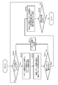
- FIG. 1 shows an example of a projected image by a projector, which is an example of the image processing apparatus of the present disclosure.
- FIG. 1A is an example in which an image processing device (projector) 100 is arranged at a position in front of the screen 10 and an image is projected and displayed on the screen 10. In this case, the projected image is not distorted.
- projector image processing device
- FIG. 1B is an example in which the projected image of the image processing device (projector) 100 is displayed from an oblique direction with respect to the screen 10.
- the projected image is distorted.
- image distortion can be corrected by applying geometric correction such as keystone correction to the projection image.
- a distortion-free image can be projected and displayed on the screen 10 by performing correction processing on the projection image and projecting the corrected image in the image processing device (projector) 100. That is, as shown in FIG. 2C, even if the projected image of the image processing device (projector) 100 is displayed from an oblique direction with respect to the screen 10, it is possible to display an image without distortion.
- This correction process can be performed manually by the operator who operates the projector, but it requires complicated work and is difficult for an inexperienced user.
- a process of projecting a specific pattern image, shooting the projected pattern image with a camera, and calculating the correction parameter from the shot pattern image is known.
- a pattern image 20 as shown in FIG. 3 is displayed, the pattern image is photographed by a camera, and the photographed image is analyzed to calculate a parameter (correction parameter) required for distortion correction.
- the correction parameter calculation process by projecting such a pattern image is a known technique described in, for example, Patent Document 1 (International Publication WO2017 / 104447) described above.
- the display of the viewing image is temporarily stopped and the pattern is displayed again. It is necessary to perform processing such as displaying an image and taking a picture with a camera, calculating a new correction parameter based on the shot pattern image, and applying the parameter to perform image correction. During this time, the display of the viewing image has to be interrupted. Such interruption of the viewing image is troublesome for the viewer who views the viewing image.
- the present disclosure makes it possible to calculate the distortion correction parameters of the projected image by the projector and perform the image correction by the calculated parameters without interrupting the presentation of the viewing image to the viewer.
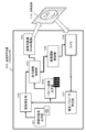
- FIG. 4 is a diagram showing a configuration example of the image processing device (projector) 100 of the present disclosure.
- the image processing device 100 includes a viewing image output unit 101, an image correction unit 102, an output image control unit 103, an image projection unit 104, a pattern image output unit 105, a camera 106, and a correction parameter calculation unit 107.
- the viewing image output unit 101 outputs a viewing image, for example, an image of a movie or the like.
- a viewing image for example, an image stored in a storage unit (not shown), or video data such as a movie input from an external server or the like via an external playback device or communication unit can be used.
- the image correction unit 102 corrects an image input from the viewing image output unit 101. That is, correction processing such as geometric correction is performed to enable distortion-free image display. Image correction processing is performed to enable projection of a distortion-free image as described with reference to FIG.
- the correction parameter applied to this correction process is input from the correction parameter calculation unit 107.
- the output image control unit 103 selects either the viewing image corrected by the image correction unit 102 or the pattern image output from the pattern image output unit 105 as an output image and outputs it to the image projection unit 104.
- the image projection unit 104 projects either a corrected viewing image or a pattern image selected by the output image control unit 103. For example, the projected image 110 shown in the figure is displayed on the screen.
- the image projection unit 104 projects an image by a pulse width modulation (PWM) method.
- PWM pulse width modulation
- the PWM method is an image output method that expresses the brightness and color of each pixel by controlling the output time of each pixel for each frame constituting the image. The details of this PWM method will be described later.
- the pattern image output unit 105 outputs a pattern image for calculating the correction parameters applied to the distortion correction of the viewing image to the output image control unit 103.
- the pattern image is, for example, the pattern image 20 described above with reference to FIG.
- the camera 106 takes an image at the timing when the pattern image is projected through the image projection unit 104.
- the image shooting control unit 108 executes the timing control of the image shooting.
- the projection pattern image taken by the camera 106 is output to the correction parameter calculation unit 107.
- the correction parameter calculation unit 107 analyzes the projection pattern image captured by the camera 106 and calculates the parameters (correction parameters) required for distortion correction. Since this correction parameter calculation process is a known process described in, for example, Patent Document 1 (International Publication WO2017 / 104447), detailed description thereof will be omitted.
- the image shooting control unit 108 controls the shooting timing of the projected image by the camera 106.
- the image shooting control unit 108 inputs pattern image output timing information from the output image control unit 103, and causes the camera 106 to perform image shooting at this timing. By this process, the camera 106 can take a projected image of the pattern image.
- the image projection unit 104 of the image processing device (projector) 100 shown in FIG. 4 performs image projection by a pulse width modulation (PWM) method.
- the PWM method is an image output method that expresses the brightness and color of each pixel by controlling the output time of each pixel for each frame constituting the image.
- FIG. 5 shows (A) Vertical sync signal (Vsync) (B) Pixel unit PWM output Each of these data is shown.
- the two pulse intervals of the vertical synchronization signal (Vsync) correspond to the output period of one frame of the image.
- the pixel with the highest brightness (255) is set to the output (light emission) state (ON) for the entire period of one frame period.
- the pixel with the lowest brightness (0) is in the output (light emission) stop state (OFF) for the entire period of one frame period.
- the pixels having the intermediate brightness (128) are set to the output (light emission) state (ON) for the first half of the one frame period. Only the (1/2 frame) shown in the figure is set to the output (light emission) state (ON). Further, a pixel having a brightness level of 1/4 (64) is set to an output (light emission) state (ON) for a quarter period of one frame period. Only the (1/4 frame) shown in the figure is set to the output (light emission) state (ON).
- the luminance value of each pixel can be expressed by the gradation of 0 to 255. It will be possible. That is, a grayscale image can be displayed as a projected image.
- FIG. 6 is a diagram showing an output (light emission) period control example corresponding to each gradation of gradations 0 to 255. In this way, it is possible to control the brightness value of each pixel by controlling the output (light emission) period within one frame period for each pixel.
- the image projection unit 104 of the image processing apparatus 100 of the present disclosure performs image projection by a pulse width modulation (PWM) method. By this process, grayscale image projection can be performed.
- PWM pulse width modulation
- a color image can be output by projecting an image for each RGB output by a pulse width modulation (PWM) method.
- PWM pulse width modulation
- the image projection unit 104 of the image processing apparatus 100 of the present disclosure can also project a color image by a pulse width modulation (PWM) method.
- the image processing device 100 of the present disclosure enables calculation of correction parameters based on the pattern image and correction of the viewing image without interrupting the presentation of the viewing image to the viewer. is there.
- details of the pattern image projection and the correction processing of the viewing image executed by the image processing apparatus 100 of the present disclosure will be described.
- FIG. 7 shows an example of an image projected by the image processing apparatus 100 of the present disclosure.
- FIG. 7 shows an example of each of the following images. (1) Viewing image (2) Pattern image
- the viewing image is, for example, an image for viewing a movie or the like.
- the pattern image is an image projected to calculate the correction parameters applied to the correction process for displaying the viewing image as a normal image without distortion.
- the "(2) pattern image” shown in the figure is an example.
- the "(2) pattern image” shown in the figure is a pattern image in which dots are arranged in a grid pattern, that is, dots are arranged at intersections of a grid composed of horizontal and vertical lines.
- a pattern image for calculating correction parameters Not limited to such a pattern image, various images can be used. A plurality of specific examples of other pattern images will be described later.
- the image processing device (projector) 100 of the present disclosure projects, for example, a pattern image in which the dots shown in the figure are arranged at the intersections of a grid composed of horizontal lines and vertical lines, and is photographed by the camera 106.
- the image processing device (projector) 100 does not face the screen, the dots of the pattern image captured by the camera are displayed deviated from the intersection position of the grid composed of the horizontal lines and the vertical lines.
- the correction parameter calculation unit 107 analyzes the arrangement of each dot in the pattern image captured by the camera 106. This analysis makes it possible to analyze, for example, the position on which each of the constituent pixels of the projected image is displayed on the screen. Using this analysis result, a correction parameter for eliminating the distortion of the display image on the screen is calculated.
- the correction parameter calculated by the correction parameter calculation unit 107 is input to the image correction unit 102, and the image correction unit 102 applies this correction parameter to execute correction processing such as geometric transformation of the viewing image.
- correction processing it is possible to project the viewing image as a distortion-free image as in the state where the image processing device (projector) 100 faces the screen.
- the image processing device 100 of the present disclosure does not interrupt the presentation of the viewing image to the viewer.
- A Pattern image display processing
- B Camera shooting process of pattern image
- C Correction parameter calculation process
- D Image correction processing for viewing
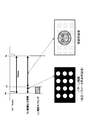
- FIG. 8 shows each of the following data as time series data.
- A Vertical sync signal (Vsync)
- B Image output period
- c Shooting timing
- the two pulse intervals of the vertical synchronization signal (Vsync) correspond to the output period of one frame of the image. Let the time tx to ty be the output period of one image frame.
- time tx to ty two images, a pattern image and a viewing image, are output (projected) by dividing the time.
- the time tx to t1 is defined as the pattern image output period
- the subsequent time t1 to ty is defined as the viewing image display period.
- This display switching control is executed by the output image control unit 103 of the image processing device 100 shown in FIG.
- the pattern image output period (tx to t1) is shown long for the sake of clarity in the figure, but for example, it is several hundredths of the one-frame output period (tx to ty), specifically, for example, 1 /. It is a very short time of about 300.
- the shooting timing is the shooting timing of the camera 106 that shoots the projected image.
- the shooting timing is set between the times tx and t1.
- the entire section of time tx to t1 is shown as the shooting timing, but the projected image may be shot at any timing within this period.
- the control of the image capturing timing is executed by the image capturing control unit 108.
- the image shooting control unit 108 inputs the pattern image output timing information from the output image control unit 103, and causes the camera 106 to perform image shooting at this timing. By this process, the camera 106 can take a projected image of the pattern image.
- the image shooting control unit 108 is between the pattern image display start time (tx) and the pattern image display end time (t1). The shooting start timing of the camera 106 is controlled so that the shooting is completed.
- the image processing apparatus 100 of the present disclosure has two images, that is, two images during the display period of one frame.
- Pattern image display period: tx to t1
- Viewing image display period: t1 to ty
- the output image control unit 103 of the image processing apparatus 100 of the present disclosure sets the pattern image output period (tx to t1) to be a very short time, for example, about 1/300 of the one frame output period (tx to ty). To control.
- the pattern image output period (tx to t1) is set to one frame output period (tx).
- the time is 1/256 or less of ⁇ ty).
- the output image control unit 103 sets the pattern so that the pixel values of the constituent pixels of the pattern image are set in the range from the minimum pixel value (0) to the minimum significant pixel value (1) of the viewing image. Controls the image output period.
- the pattern image displayed during this period is an image composed of pixel values equal to or less than the minimum significant pixel value (1) of the normal image, and the possibility of being detected by the viewer is extremely low. .. That is, the pattern image is an almost invisible image that is not noticed by the viewer.
- the pattern image projected and displayed during the time tx to t1 is captured by the camera 106, and the captured projection pattern image is output to the correction parameter calculation unit 107.
- the correction parameter calculation unit 107 analyzes the projection pattern image captured by the camera 106 and calculates the parameters (correction parameters) required for distortion correction.
- the correction parameters calculated by the correction parameter calculation unit 107 are input to the image correction unit 102.
- the image correction unit 102 applies the correction parameters calculated by the correction parameter calculation unit 107 to perform correction processing for the image input from the viewing image output unit 101. That is, correction processing such as geometric correction is performed to make the projected image a normal image without distortion.
- the image after this correction process is projected from the image projection unit 104 via the output image control unit 103.
- processing that does not stop the display of the viewing image is realized. That is, the image processing device 100 of the present disclosure does not interrupt the presentation of the viewing image to the viewer.
- D) Image correction processing for viewing It is possible to execute these series of processes.
- the frame for displaying the pattern image may be the entire display frame of the viewing image, or may be a part of the viewing image display frame. For example, only one frame may be set as the pattern image display frame every several tens of seconds to several minutes, and the pattern image may not be displayed in the other frames, and only the normal viewing image may be displayed.
- the pattern image output period (tx to t1) is set to, for example, 1/256 or less of the one-frame output period (tx to ty). Was there. This time may not always be sufficient for camera shooting.
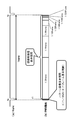
- FIG. 10 is a diagram illustrating a process of generating a composite image to be displayed in an image display period other than the pattern image display period during the one-frame display period (tx to ty).
- the composite image is an image generated according to the following (Equation 1).
- Composite image (viewing image)-(((pattern image display period) / (viewing image display period)) x (pattern image)) ... (Equation 1)
- the viewing image display period is a one-frame display period.
- the pattern image display period is a pattern image display period set within one frame period.
- the composite image calculated by the above (Equation 1) is an image obtained by subtracting the value obtained by multiplying the pattern image by the ratio of the 1-frame image display period and the pattern display period from the viewing image.
- the pattern image is, for example, an image expressed at a level from 0 to 255.
- the composite image is a composite image in which the integrated pixel value of the pattern image and the composite image output in one frame output period of the viewing image is set to be substantially equal to the pixel value of the viewing image.
- each of the following data is shown as time-series data in the same manner as described above with reference to FIG.
- the two pulse intervals of the vertical synchronization signal (Vsync) correspond to the output period of one frame of the image. Let the time tx to ty be the output period of one image frame.
- the visual recognition image By switching and displaying these two images within one frame period, the image observed by the viewer, that is, the visual recognition image becomes an image substantially equal to the viewing image as shown in the figure.
- the visual recognition image corresponds to an image calculated by the following calculation formula (Equation 2).
- Visual recognition image (pattern image) x ((pattern image display period) / (viewing image display period)) + (composite image) x (((viewing image display period)-(pattern image display period)) / ( Image display period for viewing)))) ⁇ ⁇ ⁇ (Equation 2)
- the period of the pattern image display period (tx to t2) can be set to various periods. That is, the pattern image display period can be set to be long, and the camera shooting time can be lengthened.
- the shooting timing is the shooting timing of the camera 106 that shoots the projected image.
- the shooting timing is set between the times tx and t2.
- the control of the image capturing timing is executed by the image capturing control unit 108.
- a composite image calculated according to (Equation 1) described with reference to FIG. 10 is generated, and the pattern image and the composite image are switched and displayed within one frame display period to display the pattern image.
- the period of the period (tx to t2) can be set to various periods. That is, the pattern image display period can be set to be long, and the camera shooting time can be lengthened.
- the camera 106 of the image processing device 100 shown in FIG. 4 captures an image within the projection period of the pattern image.
- the captured image of the camera 106 also includes an image around the projected pattern image.
- the captured image includes the screen and various objects around the screen.
- the correction parameter calculation unit 107 needs to perform signal processing for removing an image unrelated to the pattern from the captured image in which such various objects are reflected from the image to be analyzed. This signal processing takes more time as the number of non-analyzed image areas other than the pattern image included in the captured image increases.
- the embodiment described below has a configuration in which such an image region not to be analyzed can be easily removed.
- the removal process of the image region not to be analyzed and the subsequent correction parameter calculation process by pattern analysis are executed by the correction parameter calculation unit 107.
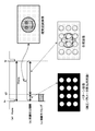
- each of the following data is shown as time series data.
- the two pulse intervals of the vertical synchronization signal (Vsync) correspond to the output period of one frame of the image. Let the time tx to ty be the output period of one image frame. The figure shows the output periods (tx to ty, ty to tz) of two consecutive frames.
- the pattern image a is output within one preceding image frame output period (tx to ty). Further, the pattern image b is output within the next image frame output period (ty to tz). The pattern image b is an inverted image of the pattern image.
- the camera 106 takes an image within the pattern image output period of each frame. As a result, the photographed image a and the photographed image b shown in the lower part of FIG. 12 are photographed. Not only the pattern image but also various surrounding objects are reflected in each photographed image.
- the correction parameter calculation unit 107 inputs the captured images a and b corresponding to these two continuous frames.
- the correction parameter calculation unit 107 calculates an analysis image from the captured images a and b corresponding to these two continuous frames according to the following equation (Equation 3).
- Image for analysis (photographed image a)-(photographed image b) ... (Equation 3)
- Equation 3 is an equation for calculating the difference between (captured image a) and (captured image b) and calculating this difference image as an analysis image.
- This difference calculation process all the same pixel values included in (captured image a) and (captured image b) are canceled. That is, the stationary subject is not included in the difference image (analysis image), and only the pattern of the pattern image remains.
- the correction parameter calculation unit 107 uses this analysis image to execute a correction parameter calculation process applied to the distortion correction. By performing such processing, it is possible to reduce the time required for the detection and exclusion processing of the non-analysis target image area other than the pattern image included in the captured image, and the processing speed can be increased.
- the examples described below are examples in the case where a rolling shutter camera is used as the camera 106 of the image processing apparatus 100 shown in FIG.
- the rolling shutter camera (Rolling Shutter Camera) has a configuration in which exposure is sequentially performed downward from the uppermost line of the image captured by the camera, and the exposure timing differs depending on the vertical position of the imaging pixel.
- each of the following data is shown as time series data.
- the two pulse intervals of the vertical synchronization signal (Vsync) correspond to the output period of one frame of the image.
- the time tx to ty be the output period of one image frame.
- two images, a pattern image and a viewing image are output (projected) by dividing the time.
- the time tx to t1 is defined as the pattern image output period
- the subsequent time t1 to ty is defined as the viewing image display period.
- This display switching control is executed by the output image control unit 103 of the image processing device 100 shown in FIG.
- the shooting timing is the shooting timing of the camera 106 that shoots the projected image.
- the camera 106 is a rolling shutter camera (Rolling Shutter Camera), and has a configuration in which exposure is sequentially performed downward from the top line of the image, depending on the vertical position of the shooting pixel. The exposure timing is different.
- the captured image of the camera becomes an image similar to the captured image shown in the figure.
- the pattern image is captured only in the middle region of the image whose exposure period matches the pattern image display period of time tx to t1, and the pattern image is not captured and the viewing image is captured in the other upper and lower regions. There is.
- the image shooting control unit 108 acquires the output timing information of the pattern image from the output image control unit 103 and executes the control of the shooting start timing in each frame.
- the correction parameter calculation unit 107 synthesizes a plurality of captured images a to c shown in FIG. 14 to generate an analysis image, and executes a correction parameter calculation process using the analysis image.
- pattern image to be applied to the correction parameter calculation an example using a pattern image in which dots are arranged in a grid pattern, that is, dots are arranged at intersections of a grid composed of horizontal lines and vertical lines has been described.
- the pattern image for calculating the correction parameter is not limited to such a pattern image, and various images can be used.
- Pattern image example 1 is a pattern image in which marks are arranged at four corners of the image.
- the deformation (distortion) of the image is a deformation mode that can be expressed by the affine conversion, correction is possible if the positions of the four corners of the image are known, and this FIG. 15 (1) pattern image example 1
- the pattern image shown in is available. Since the pattern image shown in the pattern image example 1 has few detection points, the processing is reduced.
- Pattern image example 2 is a pattern image having two rectangular areas, a peripheral area and an internal area of the pattern image. This pattern image is intended to detect four sides forming a rectangle (quadrangle), and is an example of an effective pattern image when correction is performed so as to match the image with the edge of the screen, for example.
- Pattern image example 3 is an example of using a plurality of patterns having different dot densities.
- the pattern image example 3a is composed of low-density dots
- the pattern image example 3b is composed of high-density dots.
- the pattern image of the pattern image example 3a composed of dots having low density is applied to calculate the correction parameter corresponding to the entire image.
- the deformation area of the projected image is a deformation of a part of the image, that is, a local deformation
- the pattern image of the pattern image example 3b composed of dense dots is applied to correspond to the part of the image area. Calculate the correction parameters.
- FIG. 17 (4) pattern image example 4 is a pattern image in which dots having different brightness or different colors are arranged.
- FIG. 17 (5) pattern image example 5 is a pattern image in which dots having different shapes are arranged. Similar to the above (4) pattern image example 4, it is possible to easily determine the positional relationship of each dot in the pattern image in which dots having different shapes are arranged in this way, and the correction parameter calculation process is efficiently executed. It becomes possible.
- FIG. 13 By using a pattern image in which the positional relationship of each dot can be easily identified as in the pattern image examples 4 and 5 shown in 17, it is possible to execute the composition processing of a plurality of images with high accuracy and in a short time without fail. It will be possible.
- FIG. 18 is a diagram showing a flowchart illustrating a sequence of processes executed by the image processing apparatus 100 of the present disclosure.
- the process according to the flow shown in FIG. 18 is executed under the control of a control unit such as a CPU having a program execution function according to a program stored in the storage unit of the image processing device 100, for example.
- a control unit such as a CPU having a program execution function according to a program stored in the storage unit of the image processing device 100, for example.
- the processing of each step of the flow shown in FIG. 18 will be sequentially described.
- Step S101 the image processing device 100 determines in step S101 whether or not it is the output timing of the pattern image.
- the output timing of the pattern image is predetermined. For example, as described above with reference to FIGS. 6 and 7, at the start timing of one image frame, the pattern image output period is, for example, 1/256 or less of the one frame output period.
- step S101 the output image control unit 103 shown in FIG. 4 determines whether or not it is the output timing of the pattern image.
- the frame for displaying the pattern image may be the entire display frame of the viewing image, or may be a part of the display frame of the viewing image. For example, only one frame may be set as the pattern image display frame every several tens of seconds to several minutes, and the pattern image may not be displayed in the other frames, and only the normal viewing image may be displayed.
- the output image control unit 103 determines that it is the frame start timing of the pattern image display frame defined in advance, the output image control unit 103 proceeds to step S102.
- Step S102 When it is determined in step S101 that it is the frame start timing of the pattern image display frame defined in advance, the output image control unit 103 shown in FIG. 4 inputs a pattern image from the pattern image output unit 105 in step S102. It is output via the image projection unit 104.
- the camera 106 executes the pattern image shooting process.
- the image shooting control process of the camera 106 is executed by the image shooting control unit 108.
- the image shooting control unit 108 inputs the pattern image output timing information from the output image control unit 103, and causes the camera 106 to perform image shooting at this timing. By this process, the camera 106 can take a projected image of the pattern image.
- Step S103 Next, in step S103, a parameter (correction parameter) required for distortion correction of the projected image is calculated using the pattern image captured by the camera 106. This process is a process executed by the correction parameter calculation unit 107.
- the correction parameter calculation unit 107 analyzes the projection pattern image captured by the camera 106 and calculates the parameters (correction parameters) required for distortion correction.
- the correction parameter calculation unit 107 analyzes, for example, the arrangement of dots in the pattern image captured by the camera 106. This analysis makes it possible to analyze, for example, the position on which each of the constituent pixels of the projected image is displayed on the screen. Using this analysis result, a correction parameter for eliminating the distortion of the display image on the screen is calculated.
- the correction parameters calculated by the correction parameter calculation unit 107 are input to the image correction unit 102.
- step S104 the correction process of the viewing image using the correction parameter calculated by the correction parameter calculation unit 107 in step S103 is executed.
- This process is a process executed by the image correction unit 102.
- the image correction unit 102 applies the correction parameters calculated by the correction parameter calculation unit 107 to execute correction processing such as geometric transformation of the viewing image.
- correction processing it is possible to project the viewing image as a distortion-free image as in the state where the image processing device (projector) 100 faces the screen.
- step S105 it is determined whether or not the projection process of the viewing image is completed. If it is not completed, the process of step S101 and subsequent steps is repeated.
- This iterative processing for example, even if the orientation of the image processing device (projector) 100 changes during image projection, new correction parameters are calculated according to the orientation of the image processing device (projector) 100 after the change. , The image correction process to which the calculated correction parameters are applied is executed, and it becomes possible to continuously display the viewing image without distortion. If it is determined in step S105 that the projection process of the viewing image is completed, the process is terminated.
- the image processing apparatus 100 of the present disclosure executes processing in a sequence according to the flow shown in FIG. By executing the processing according to the sequence according to this flow, the image processing apparatus 100 of the present disclosure does not interrupt the presentation of the viewing image to the viewer.
- A Pattern image display processing
- B Camera shooting process of pattern image
- C Correction parameter calculation process
- D Image correction processing for viewing
- the sequence described with reference to FIG. 18 is a basic processing sequence of processing executed by the image processing apparatus 100 of the present disclosure.
- Steps S201 to S203 The processes of steps S201 to S203 are the same as the processes of steps S101 to S103 of the flow described above with reference to FIG.
- the image processing device 100 determines in step S201 whether or not it is the output timing of the pattern image.
- the output image control unit 103 determines that it is the frame start timing of the pattern image display frame defined in advance, the output image control unit 103 proceeds to step S202.
- step S202 the output image control unit 103 inputs a pattern image from the pattern image output unit 105 and outputs it via the image projection unit 104. Further, at this pattern image output timing, the camera 106 executes the pattern image shooting process.
- step S203 the pattern image captured by the camera 106 is used to execute a calculation process of parameters (correction parameters) required for distortion correction of the projected image.
- This process is a process executed by the correction parameter calculation unit 107.
- the correction parameter calculation unit 107 analyzes the projection pattern image captured by the camera 106 and calculates the parameters (correction parameters) required for distortion correction. However, the correction parameter may not be calculated depending on the distortion mode of the image distortion.
- Step S204 it is determined whether or not the calculation of the correction parameter in step S203 was successful. This process is also a process executed by the correction parameter calculation unit 107.
- step S205 If it is determined that the calculation of the correction parameter is successful, the process proceeds to step S205. On the other hand, if it is determined that the calculation of the correction parameter has failed, the process proceeds to step S211.
- Step S211 If it is determined in step S204 that the calculation of the correction parameter has failed, the process proceeds to step S211.
- step S211 the pattern image is changed. This process is executed by the pattern image output unit 105.
- the correction parameter calculation unit 107 determines that the calculation of the correction parameter has failed, it outputs control information (command) for changing the pattern image to be output to the pattern image output unit 105.
- the pattern image output unit 105 changes the pattern image to be output in response to the input of control information (command) from the correction parameter calculation unit 107.
- step S204 the process returns to step S201, and the processes of steps S201 to S204 are executed using the changed pattern image. If it is finally determined in step S204 that the calculation of the correction parameter is successful, the process proceeds to step S205.
- step S205 correction processing of the viewing image using the correction parameter calculated by the correction parameter calculation unit 107 in step S203 is executed.
- This process is a process executed by the image correction unit 102.
- the image correction unit 102 applies the correction parameters calculated by the correction parameter calculation unit 107 to execute correction processing such as geometric transformation of the viewing image.
- correction processing it is possible to project the viewing image as a distortion-free image as in the state where the image processing device (projector) 100 faces the screen.
- step S206 it is determined whether or not the projection process of the viewing image is completed. If it is not completed, the process of step S201 and subsequent steps is repeated.
- This iterative processing for example, even if the orientation of the image processing device (projector) 100 changes during image projection, new correction parameters are calculated according to the orientation of the image processing device (projector) 100 after the change. , The image correction process to which the calculated correction parameters are applied is executed, and it becomes possible to continuously display the viewing image without distortion. If it is determined in step S206 that the projection process of the viewing image is completed, the process is terminated.
- the image processing device 100 of the present disclosure does not interrupt the presentation of the viewing image to the viewer.
- A Pattern image display processing
- B Camera shooting process of pattern image
- C Correction parameter calculation process
- D Image correction processing for viewing
- FIG. 20 is a diagram showing a specific hardware configuration of the image processing apparatus of the present disclosure. The components of the hardware configuration shown in FIG. 20 will be described.
- the CPU (Central Processing Unit) 301 functions as a data processing unit that executes various processes according to a program stored in the ROM (Read Only Memory) 302 or the storage unit 308. For example, the process according to the sequence described in the above-described embodiment is executed.
- the RAM (Random Access Memory) 303 stores programs and data executed by the CPU 301. These CPU 301, ROM 302, and RAM 303 are connected to each other by a bus 304.
- the CPU 301 is connected to the input / output interface 305 via the bus 304, and the input / output interface 305 has an input unit 306 composed of various switches, a keyboard, a touch panel, a mouse, a microphone, a camera, etc. Is connected.
- the output unit 307 includes a projector that executes PWM image output.
- the CPU 301 inputs commands, status data, and the like input from the input unit 306, executes various processes, and outputs the process results to, for example, the output unit 307.
- the storage unit 308 connected to the input / output interface 305 is composed of, for example, a hard disk or the like, and stores a program executed by the CPU 301 and various data.
- the communication unit 309 functions as a transmission / reception unit for data communication via a network such as the Internet or a local area network, and communicates with an external device.
- the drive 310 connected to the input / output interface 305 drives a removable medium 311 such as a magnetic disk, an optical disk, a magneto-optical disk, or a semiconductor memory such as a memory card, and records or reads data.
- a removable medium 311 such as a magnetic disk, an optical disk, a magneto-optical disk, or a semiconductor memory such as a memory card
- the technology disclosed in the present specification can have the following configuration.
- An image projection unit that executes image projection processing by the pulse width modulation (PWM) method, and An output image control unit that sets a part of the one-frame output period of the viewing image as the output period of the pattern image used to calculate the image correction parameters.
- a correction parameter calculation unit that calculates image correction parameters using a shooting pattern image taken by a camera during the output period of the pattern image, and a correction parameter calculation unit.
- An image processing device having an image correction unit that executes correction processing of the viewing image by using the image correction parameter calculated by the correction parameter calculation unit.
- the output image control unit is The image processing apparatus according to (1), wherein output control is executed in which a part of the one-frame output period of the viewing image is set as the output period of the pattern image and the remaining period is set as the output period of the viewing image.
- the image processing device further A camera that captures the pattern image and The image processing apparatus according to (1) or (2), which has an image shooting control unit that executes image shooting by the camera during the output period of the pattern image.
- the output image control unit is 4. The method according to any one of (1) to (3), wherein the output period of the pattern image is controlled so that the pixel value of the pattern image is in the range from the lowest pixel value of the viewing image to less than the lowest significant pixel value.
- Image processing device 4.
- the output image control unit is When the pixel value of the constituent pixels of the viewing image is an image in which an 8-bit pixel value in the range of 0 to 255 is set, The output period of the pattern image is controlled from (1) to (4) so that the pixel value of the pattern image is in the range from the lowest pixel value (0) of the viewing image to less than the lowest significant pixel value (1). )
- the image processing apparatus according to any one.
- the output image control unit is Output control in which a part of the one-frame output period of the viewing image is the output period of the pattern image, and the remaining period is the output period of the composite image generated by the compositing process of the viewing image and the pattern image.
- the composite image is a composite image in which the integrated pixel value of the pattern image and the composite image output in one frame output period of the viewing image is set to be substantially equal to the pixel value of the viewing image (6). ).
- the image processing apparatus The image processing apparatus.
- the output image control unit is The output period of the pattern image is set in the 1-frame output period of the preceding viewing image, and the output period of the inverted image of the pattern image is set in the 1-frame output period of the subsequent viewing image.
- the correction parameter calculation unit The image according to (1), wherein the correction parameter calculation process is executed using the difference image between the captured image of the pattern image captured during the preceding frame output period and the inverted image of the pattern image captured during the subsequent frame output period. Processing equipment.
- the output image control unit is The image processing apparatus according to any one of (1) to (8), which switches and outputs a plurality of different pattern images.
- the image processing apparatus has an image projection unit that executes image projection processing by a pulse width modulation (PWM) method.
- the output image control unit An output image control step that sets a part of the one-frame output period of the viewing image as the output period of the pattern image used to calculate the image correction parameters, and A correction parameter calculation step in which the correction parameter calculation unit calculates an image correction parameter using a shooting pattern image taken by a camera during the output period of the pattern image.
- An image processing method in which an image correction unit executes an image correction step of executing the correction processing of the viewing image by using the image correction parameter calculated by the correction parameter calculation unit.
- a program that executes image processing in an image processing device has an image projection unit that executes image projection processing by a pulse width modulation (PWM) method.
- the program An output image control step that causes the output image control unit to set a part of the one-frame output period of the viewing image as the output period of the pattern image used for calculating the image correction parameter.
- the program to be executed.
- the series of processes described in the specification can be executed by hardware, software, or a composite configuration of both.
- executing processing by software install the program that records the processing sequence in the memory in the computer built in the dedicated hardware and execute it, or execute the program on a general-purpose computer that can execute various processing. It can be installed and run.
- the program can be pre-recorded on a recording medium.
- LAN Local Area Network
- the various processes described in the specification are not only executed in chronological order according to the description, but may also be executed in parallel or individually as required by the processing capacity of the device that executes the processes.
- the system is a logical set configuration of a plurality of devices, and the devices having each configuration are not limited to those in the same housing.
- a device that captures a pattern image, calculates correction parameters, and corrects the image without interrupting the presentation of the viewing image projected by the projector.
- the method is realized. Specifically, for example, an image projection unit that executes image projection processing by a pulse width modulation (PWM) method and a pattern image output that uses a part of the one-frame output period of the viewing image for calculating image correction parameters.
- PWM pulse width modulation
- the output image control unit controls, for example, the pattern image output period so that the pixel value of the pattern image is in the range from the lowest pixel value of the viewing image to less than the lowest significant pixel value.
Abstract
Provided are a device and method for photographing a pattern image and performing correction parameter calculation and image correction without interrupting the presentation of an image for viewing that is projected by a projector. The present invention comprises: an image projection unit for executing an image projection process by a pulse with modulation (PWM) scheme; an output image control unit for selecting a partial period of the one-frame output period of an image for viewing as a pattern image output period utilized for calculating an image correction parameter; a correction parameter calculation unit for calculating an image correction parameter utilizing a photographed pattern image having been photographed by a camera in the pattern image output period; and an image correction unit for executing a correction process for the image for viewing utilizing the image correction parameter. The output image control unit controls the pattern image output period so that, for example, the pixel value of the pattern image falls within a range from the lowest pixel value of the image for viewing to less than a lowest significant pixel value.
Description
本開示は、画像処理装置、および画像処理方法、並びにプログラムに関する。さらに詳細には、プロジェクタによる投影画像の補正を実行する画像処理装置、および画像処理方法、並びにプログラムに関する。
The present disclosure relates to an image processing apparatus, an image processing method, and a program. More specifically, the present invention relates to an image processing apparatus for performing correction of a projected image by a projector, an image processing method, and a program.
プロジェクタを用いてスクリーンに画像を投影する際、スクリーンの正面にプロジェクタを配置できない場合、スクリーンの右斜め方向や左斜め方向から画像投影を行うことがある。しかし、斜め方向から画像投影を行うとスクリーンの画像は歪んだ画像となる。このような画像歪みを解消する補正処理をプロジェクタ内部で実行して画像投影を行うことで歪みのない画像を表示することが可能となる。
When projecting an image on the screen using a projector, if the projector cannot be placed in front of the screen, the image may be projected diagonally to the right or diagonally to the left of the screen. However, when the image is projected from an oblique direction, the image on the screen becomes a distorted image. By executing a correction process for eliminating such image distortion inside the projector and projecting the image, it is possible to display an image without distortion.
このような画像歪みの補正処理について開示した従来技術として、例えば特許文献1(国際公開WO2017/104447号公報)がある。
この文献は、予め規定した補正パラメータ算出用のパターン画像をスクリーンに投影して、スクリーンに表示されたパターン画像をカメラで撮影し、撮影したパターン画像を利用して歪み態様を解析し、解析結果に基づいて投影画像の補正処理を行う構成を開示している。 As a prior art disclosed regarding such image distortion correction processing, for example, Patent Document 1 (International Publication WO2017 / 104447) is available.
In this document, a predetermined pattern image for calculating correction parameters is projected on a screen, a pattern image displayed on the screen is photographed by a camera, and a distortion mode is analyzed using the photographed pattern image, and the analysis result is obtained. Discloses a configuration in which a projection image correction process is performed based on the above.
しかし、この文献に記載の構成では、視聴用画像の表示を停止して補正パラメータを算出するための専用パターン画像を一定時間、表示することが必要となる。すなわち、パターン画像の表示期間は、視聴用画像の表示を停止しなければならない。
However, in the configuration described in this document, it is necessary to stop the display of the viewing image and display the dedicated pattern image for calculating the correction parameter for a certain period of time. That is, the display of the viewing image must be stopped during the display period of the pattern image.
従って、例えば、視聴用画像の表示開始後、プロジェクタに人が触れて投影方向が変化して投影画像に歪みが発生した場合には、視聴用画像の表示を一旦、停止して、再度、パターン画像の表示とカメラ撮影を行い、撮影したパターン画像に基づく新たな補正パラメータを算出して、そのパラメータを適用して画像補正を行うといった処理を行わなければならない。この間、視聴用画像の表示は中断せざる得ないことになる。
このような視聴用画像の中断は、視聴用画像を視聴する視聴者にとって煩わしいものである。 Therefore, for example, when a person touches the projector after the display of the viewing image is started and the projection direction changes and the projected image is distorted, the display of the viewing image is temporarily stopped and the pattern is displayed again. It is necessary to perform processing such as displaying an image and taking a picture with a camera, calculating a new correction parameter based on the shot pattern image, and applying the parameter to perform image correction. During this time, the display of the viewing image has to be interrupted.
Such interruption of the viewing image is troublesome for the viewer who views the viewing image.
本開示は、例えば上記問題点に鑑みてなされたものであり、視聴者に対する視聴用画像の提示を中断することなく、プロジェクタによる投影画像の歪み補正のパラメータを算出して、算出したパラメータによる画像補正を行うことを可能とした画像処理装置、および画像処理方法、並びにプログラムを提供することを目的とする。
The present disclosure has been made in view of the above problems, for example, by calculating the parameters of distortion correction of the projected image by the projector without interrupting the presentation of the viewing image to the viewer, and the image based on the calculated parameters. It is an object of the present invention to provide an image processing apparatus capable of performing correction, an image processing method, and a program.
本開示の第1の側面は、
パルス幅変調(PWM:Pulse Width Modulation)方式による画像投影処理を実行する画像投影部と、
視聴用画像の1フレーム出力期間の一部期間を画像補正パラメータの算出に利用するパターン画像の出力期間として設定する出力画像制御部と、
前記パターン画像の出力期間にカメラ撮影された撮影パターン画像を利用して画像補正パラメータを算出する補正パラメータ算出部と、
前記補正パラメータ算出部が算出した画像補正パラメータを利用して前記視聴用画像の補正処理を実行する画像補正部を有する画像処理装置にある。 The first aspect of the disclosure is
An image projection unit that executes image projection processing by the pulse width modulation (PWM) method, and
An output image control unit that sets a part of the one-frame output period of the viewing image as the output period of the pattern image used to calculate the image correction parameters.
A correction parameter calculation unit that calculates image correction parameters using a shooting pattern image taken by a camera during the output period of the pattern image, and a correction parameter calculation unit.
The image processing apparatus has an image correction unit that executes correction processing of the viewing image by using the image correction parameter calculated by the correction parameter calculation unit.
さらに、本開示の第2の側面は、
画像処理装置において実行する画像処理方法であり、
前記画像処理装置は、パルス幅変調(PWM:Pulse Width Modulation)方式による画像投影処理を実行する画像投影部を有し、
出力画像制御部が、
視聴用画像の1フレーム出力期間の一部期間を画像補正パラメータの算出に利用するパターン画像の出力期間として設定する出力画像制御ステップと、
補正パラメータ算出部が、前記パターン画像の出力期間にカメラ撮影された撮影パターン画像を利用して画像補正パラメータを算出する補正パラメータ算出ステップと、
画像補正部が、前記補正パラメータ算出部が算出した画像補正パラメータを利用して前記視聴用画像の補正処理を実行する画像補正ステップを実行する画像処理方法にある。 Further, the second aspect of the present disclosure is
This is an image processing method executed in an image processing device.
The image processing apparatus has an image projection unit that executes image projection processing by a pulse width modulation (PWM) method.
The output image control unit
An output image control step that sets a part of the one-frame output period of the viewing image as the output period of the pattern image used to calculate the image correction parameters, and
A correction parameter calculation step in which the correction parameter calculation unit calculates an image correction parameter using a shooting pattern image taken by a camera during the output period of the pattern image.
In the image processing method, the image correction unit executes an image correction step of executing the correction processing of the viewing image by using the image correction parameter calculated by the correction parameter calculation unit.
さらに、本開示の第3の側面は、
画像処理装置において画像処理を実行させるプログラムであり、
前記画像処理装置は、パルス幅変調(PWM:Pulse Width Modulation)方式による画像投影処理を実行する画像投影部を有し、
前記プログラムは、
前記出力画像制御部に、視聴用画像の1フレーム出力期間の一部期間を画像補正パラメータの算出に利用するパターン画像の出力期間として設定させる出力画像制御ステップと、
補正パラメータ算出部に、前記パターン画像の出力期間にカメラ撮影された撮影パターン画像を利用して画像補正パラメータを算出させる補正パラメータ算出ステップと、
画像補正部に、前記補正パラメータ算出部が算出した画像補正パラメータを利用して前記視聴用画像の補正処理を実行させる画像補正ステップを、
実行させるプログラムにある。 Further, the third aspect of the present disclosure is
A program that executes image processing in an image processing device.
The image processing apparatus has an image projection unit that executes image projection processing by a pulse width modulation (PWM) method.
The program
An output image control step that causes the output image control unit to set a part of the one-frame output period of the viewing image as the output period of the pattern image used for calculating the image correction parameter.
A correction parameter calculation step of causing the correction parameter calculation unit to calculate an image correction parameter using a shooting pattern image taken by a camera during the output period of the pattern image.
An image correction step of causing the image correction unit to execute the correction process of the viewing image by using the image correction parameter calculated by the correction parameter calculation unit.
It is in the program to be executed.
なお、本開示のプログラムは、例えば、様々なプログラム・コードを実行可能な情報処理装置やコンピュータ・システムに対して、コンピュータ可読な形式で提供する記憶媒体、通信媒体によって提供可能なプログラムである。このようなプログラムをコンピュータ可読な形式で提供することにより、情報処理装置やコンピュータ・システム上でプログラムに応じた処理が実現される。
The program of the present disclosure is, for example, a program that can be provided by a storage medium or a communication medium that is provided in a computer-readable format to an information processing device or a computer system that can execute various program codes. By providing such a program in a computer-readable format, processing according to the program can be realized on an information processing device or a computer system.
本開示のさらに他の目的、特徴や利点は、後述する本開示の実施例や添付する図面に基づくより詳細な説明によって明らかになるであろう。なお、本明細書においてシステムとは、複数の装置の論理的集合構成であり、各構成の装置が同一筐体内にあるものには限らない。
Still other objectives, features and advantages of the present disclosure will be clarified by more detailed description based on the examples of the present disclosure and the accompanying drawings described below. In the present specification, the system is a logical set configuration of a plurality of devices, and the devices having each configuration are not limited to those in the same housing.
本開示の一実施例の構成によれば、プロジェクタが投影する視聴用画像の提示を中断することなく、パターン画像を撮影して補正パラメータ算出と画像補正を行う装置、方法が実現される。
具体的には、例えば、パルス幅変調(PWM)方式による画像投影処理を実行する画像投影部と、視聴用画像の1フレーム出力期間の一部期間を画像補正パラメータの算出に利用するパターン画像出力期間とする出力画像制御部と、パターン画像出力期間にカメラ撮影された撮影パターン画像を利用して画像補正パラメータを算出する補正パラメータ算出部と、画像補正パラメータを利用して視聴用画像の補正処理を実行する画像補正部を有する。出力画像制御部は、例えば、パターン画像の画素値が視聴用画像の最低画素値から最低有意画素値未満の範囲となるようにパターン画像出力期間を制御する。
本構成により、プロジェクタが投影する視聴用画像の提示を中断することなく、パターン画像を撮影して補正パラメータ算出と画像補正を行う装置、方法が実現される。
なお、本明細書に記載された効果はあくまで例示であって限定されるものではなく、また付加的な効果があってもよい。 According to the configuration of one embodiment of the present disclosure, a device and a method of capturing a pattern image, calculating correction parameters, and performing image correction are realized without interrupting the presentation of the viewing image projected by the projector.
Specifically, for example, an image projection unit that executes image projection processing by a pulse width modulation (PWM) method, and a pattern image output that uses a part of the one-frame output period of the viewing image for calculating image correction parameters. An output image control unit for the period, a correction parameter calculation unit that calculates image correction parameters using the shooting pattern image taken by the camera during the pattern image output period, and a viewing image correction process using the image correction parameters. It has an image correction unit that executes the above. The output image control unit controls, for example, the pattern image output period so that the pixel value of the pattern image is in the range from the lowest pixel value of the viewing image to less than the lowest significant pixel value.
With this configuration, a device and a method for capturing a pattern image, calculating correction parameters, and performing image correction are realized without interrupting the presentation of the viewing image projected by the projector.
It should be noted that the effects described in the present specification are merely exemplary and not limited, and may have additional effects.
以下、図面を参照しながら本開示の画像処理装置、および画像処理方法、並びにプログラムの詳細について説明する。なお、説明は以下の項目に従って行なう。
1.プロジェクタによる投影画像の歪みと補正処理の概要について
2.本開示の画像処理装置の構成例について
3.パルス幅変調(PWM:Pulse Width Modulation)方式による画像投影処理について
4.本開示の画像処理装置の実行するパターン画像投影と視聴用画像の補正処理の詳細について
5.その他の実施例について
5-1.カメラ撮影時間(露光時間)を長くすることを可能とした実施例
5-2.パターン検出、解析を容易にすることを可能とした実施例について
5-3.パターン画像の撮影カメラとしてローリングシャッターカメラを用いた実施例について
5-4.その他のパターン画像の例について
6.画像処理装置の実行する処理のシーケンスについて
7.画像処理装置のハードウェア構成例について
8.本開示の構成のまとめ Hereinafter, the details of the image processing apparatus, the image processing method, and the program of the present disclosure will be described with reference to the drawings. The explanation will be given according to the following items.
1. 1. Outline of distortion and correction processing of projected image by projector 2. Regarding the configuration example of the image processing apparatus of the present disclosure. Image projection processing by pulse width modulation (PWM)method 4. 5. Details of pattern image projection and image correction processing for viewing executed by the image processing apparatus of the present disclosure. About other examples 5-1. Example 5-2 which made it possible to lengthen the camera shooting time (exposure time). Examples that made it possible to facilitate pattern detection and analysis 5-3. Example of using a rolling shutter camera as a pattern image shooting camera 5-4. Examples of other pattern images 6. About the sequence of processing executed by the image processing device 7. About the hardware configuration example of the image processing device 8. Summary of the structure of this disclosure
1.プロジェクタによる投影画像の歪みと補正処理の概要について
2.本開示の画像処理装置の構成例について
3.パルス幅変調(PWM:Pulse Width Modulation)方式による画像投影処理について
4.本開示の画像処理装置の実行するパターン画像投影と視聴用画像の補正処理の詳細について
5.その他の実施例について
5-1.カメラ撮影時間(露光時間)を長くすることを可能とした実施例
5-2.パターン検出、解析を容易にすることを可能とした実施例について
5-3.パターン画像の撮影カメラとしてローリングシャッターカメラを用いた実施例について
5-4.その他のパターン画像の例について
6.画像処理装置の実行する処理のシーケンスについて
7.画像処理装置のハードウェア構成例について
8.本開示の構成のまとめ Hereinafter, the details of the image processing apparatus, the image processing method, and the program of the present disclosure will be described with reference to the drawings. The explanation will be given according to the following items.
1. 1. Outline of distortion and correction processing of projected image by projector 2. Regarding the configuration example of the image processing apparatus of the present disclosure. Image projection processing by pulse width modulation (PWM)
[1.プロジェクタによる投影画像の歪みと補正処理の概要について]
まず、図1以下を参照してプロジェクタによる投影画像の歪みと補正処理の概要について説明する。 [1. Outline of distortion and correction processing of projected image by projector]
First, the outline of the distortion and correction processing of the projected image by the projector will be described with reference to FIGS. 1 and 1 and below.
まず、図1以下を参照してプロジェクタによる投影画像の歪みと補正処理の概要について説明する。 [1. Outline of distortion and correction processing of projected image by projector]
First, the outline of the distortion and correction processing of the projected image by the projector will be described with reference to FIGS. 1 and 1 and below.
図1には本開示の画像処理装置の一例であるプロジェクタによる投影画像の例を示している。
図1(a)は、スクリーン10の正面位置に画像処理装置(プロジェクタ)100を配置して、スクリーン10に画像を投影表示した例である。
この場合、投影画像には歪みが発生しない。 FIG. 1 shows an example of a projected image by a projector, which is an example of the image processing apparatus of the present disclosure.
FIG. 1A is an example in which an image processing device (projector) 100 is arranged at a position in front of the screen 10 and an image is projected and displayed on the screen 10.
In this case, the projected image is not distorted.
一方、図1(b)は、スクリーン10に対して斜め方向から画像処理装置(プロジェクタ)100の投影画像を表示した例である。
この場合、投影画像には歪みが発生する。
このような画像歪みは、例えば台形補正等の幾何補正を投影用画像に施すことで修正することができる。 On the other hand, FIG. 1B is an example in which the projected image of the image processing device (projector) 100 is displayed from an oblique direction with respect to the screen 10.
In this case, the projected image is distorted.
Such image distortion can be corrected by applying geometric correction such as keystone correction to the projection image.
すなわち、画像処理装置(プロジェクタ)100内で、投影用画像に対して補正処理を施して補正後の画像を投影することで歪みのない画像をスクリーン10上に投影表示することができる。
すなわち、図2(c)に示すように、スクリーン10に対して斜め方向から画像処理装置(プロジェクタ)100の投影画像を表示しても歪みの無い画像を表示することが可能となる。 That is, a distortion-free image can be projected and displayed on the screen 10 by performing correction processing on the projection image and projecting the corrected image in the image processing device (projector) 100.
That is, as shown in FIG. 2C, even if the projected image of the image processing device (projector) 100 is displayed from an oblique direction with respect to the screen 10, it is possible to display an image without distortion.
この補正処理は、プロジェクタを操作する操作者の手動により行うことも可能であるが、煩雑な作業が必要であり、また不慣れなユーザにとっては困難な作業となる。
This correction process can be performed manually by the operator who operates the projector, but it requires complicated work and is difficult for an inexperienced user.
この画像歪み補正のためのパラメータを算出する処理として、特定のパターン画像を投影して、投影されたパターン画像をカメラで撮影して、撮影されたパターン画像から補正パラメータを算出する処理が知られている。
例えば図3に示すようなパターン画像20を表示し、このパターン画像をカメラで撮影し、撮影画像を解析することで歪み補正に必要となるパラメータ(補正パラメータ)を算出することができる。
なお、このようなパターン画像の投影による補正パラメータ算出処理は、例えば前述の特許文献1(国際公開WO2017/104447号公報)にも記載された公知技術である。 As a process of calculating the parameter for this image distortion correction, a process of projecting a specific pattern image, shooting the projected pattern image with a camera, and calculating the correction parameter from the shot pattern image is known. ing.
For example, a pattern image 20 as shown in FIG. 3 is displayed, the pattern image is photographed by a camera, and the photographed image is analyzed to calculate a parameter (correction parameter) required for distortion correction.
The correction parameter calculation process by projecting such a pattern image is a known technique described in, for example, Patent Document 1 (International Publication WO2017 / 104447) described above.
しかし、前述したように、特許文献1に記載の構成では、視聴用画像の表示を停止してパターン画像の表示を行って補正パラメータを求める処理が必要となる。
すなわち、パターン画像の表示期間は、視聴用画像の表示を停止しなければならない。 However, as described above, in the configuration described inPatent Document 1, it is necessary to stop the display of the viewing image, display the pattern image, and obtain the correction parameter.
That is, the display of the viewing image must be stopped during the display period of the pattern image.
すなわち、パターン画像の表示期間は、視聴用画像の表示を停止しなければならない。 However, as described above, in the configuration described in
That is, the display of the viewing image must be stopped during the display period of the pattern image.
従って、例えば、視聴用画像の表示開始後、プロジェクタに人が触れて投影方向が変化して投影画像に歪みが発生した場合には、視聴用画像の表示を一旦、停止して、再度、パターン画像の表示とカメラ撮影を行い、撮影したパターン画像に基づく新たな補正パラメータを算出して、そのパラメータを適用して画像補正を行うといった処理を行わなければならない。この間、視聴用画像の表示は中断せざる得ないことになる。
このような視聴用画像の中断は、視聴用画像を視聴する視聴者にとって煩わしいものである。 Therefore, for example, when a person touches the projector after the display of the viewing image is started and the projection direction changes and the projected image is distorted, the display of the viewing image is temporarily stopped and the pattern is displayed again. It is necessary to perform processing such as displaying an image and taking a picture with a camera, calculating a new correction parameter based on the shot pattern image, and applying the parameter to perform image correction. During this time, the display of the viewing image has to be interrupted.
Such interruption of the viewing image is troublesome for the viewer who views the viewing image.
このような視聴用画像の中断は、視聴用画像を視聴する視聴者にとって煩わしいものである。 Therefore, for example, when a person touches the projector after the display of the viewing image is started and the projection direction changes and the projected image is distorted, the display of the viewing image is temporarily stopped and the pattern is displayed again. It is necessary to perform processing such as displaying an image and taking a picture with a camera, calculating a new correction parameter based on the shot pattern image, and applying the parameter to perform image correction. During this time, the display of the viewing image has to be interrupted.
Such interruption of the viewing image is troublesome for the viewer who views the viewing image.
本開示は、視聴者に対する視聴用画像の提示を中断することなく、プロジェクタによる投影画像の歪み補正用パラメータを算出して、算出したパラメータによる画像補正を行うことを可能とするものである。
The present disclosure makes it possible to calculate the distortion correction parameters of the projected image by the projector and perform the image correction by the calculated parameters without interrupting the presentation of the viewing image to the viewer.
[2.本開示の画像処理装置の構成例について]
次に、本開示の画像処理装置の構成例について説明する。
図4は、本開示の画像処理装置(プロジェクタ)100の構成例を示す図である。
図4に示すように、画像処理装置100は、視聴用画像出力部101、画像補正部102、出力画像制御部103、画像投影部104、パターン画像出力部105、カメラ106、補正パラメータ算出部107、画像撮影制御部108を有する。 [2. About the configuration example of the image processing apparatus of the present disclosure]
Next, a configuration example of the image processing apparatus of the present disclosure will be described.
FIG. 4 is a diagram showing a configuration example of the image processing device (projector) 100 of the present disclosure.
As shown in FIG. 4, the image processing device 100 includes a viewingimage output unit 101, an image correction unit 102, an output image control unit 103, an image projection unit 104, a pattern image output unit 105, a camera 106, and a correction parameter calculation unit 107. , Has an imaging control unit 108.
次に、本開示の画像処理装置の構成例について説明する。
図4は、本開示の画像処理装置(プロジェクタ)100の構成例を示す図である。
図4に示すように、画像処理装置100は、視聴用画像出力部101、画像補正部102、出力画像制御部103、画像投影部104、パターン画像出力部105、カメラ106、補正パラメータ算出部107、画像撮影制御部108を有する。 [2. About the configuration example of the image processing apparatus of the present disclosure]
Next, a configuration example of the image processing apparatus of the present disclosure will be described.
FIG. 4 is a diagram showing a configuration example of the image processing device (projector) 100 of the present disclosure.
As shown in FIG. 4, the image processing device 100 includes a viewing
視聴用画像出力部101は、視聴用画像、例えば映画等の画像を出力する。なお、視聴用画像は、例えば図示しない記憶部に格納された画像、あるいは外部の再生装置や通信部を介して外部サーバ等から入力する映画等の映像データ等が利用可能である。
The viewing image output unit 101 outputs a viewing image, for example, an image of a movie or the like. As the viewing image, for example, an image stored in a storage unit (not shown), or video data such as a movie input from an external server or the like via an external playback device or communication unit can be used.
画像補正部102は、視聴用画像出力部101から入力する画像の補正処理を行う。すなわち、歪みのない画像表示を可能とするための幾何補正等の補正処理を行う。
図2を参照して説明したような歪みのない画像を投影可能とするための画像補正処理を行う。なお、この補正処理に適用する補正パラメータは、補正パラメータ算出部107から入力する。 Theimage correction unit 102 corrects an image input from the viewing image output unit 101. That is, correction processing such as geometric correction is performed to enable distortion-free image display.
Image correction processing is performed to enable projection of a distortion-free image as described with reference to FIG. The correction parameter applied to this correction process is input from the correctionparameter calculation unit 107.
図2を参照して説明したような歪みのない画像を投影可能とするための画像補正処理を行う。なお、この補正処理に適用する補正パラメータは、補正パラメータ算出部107から入力する。 The
Image correction processing is performed to enable projection of a distortion-free image as described with reference to FIG. The correction parameter applied to this correction process is input from the correction
出力画像制御部103は、画像補正部102が補正した視聴用画像、または、パターン画像出力部105から出力されるパターン画像のいずれかを出力画像として選択して画像投影部104に出力する。
The output image control unit 103 selects either the viewing image corrected by the image correction unit 102 or the pattern image output from the pattern image output unit 105 as an output image and outputs it to the image projection unit 104.
画像投影部104は、出力画像制御部103が選択した補正済みの視聴用画像、または、パターン画像のいずれかを投影する。
例えば図に示す投影画像110がスクリーンに表示される。 Theimage projection unit 104 projects either a corrected viewing image or a pattern image selected by the output image control unit 103.
For example, the projected image 110 shown in the figure is displayed on the screen.
例えば図に示す投影画像110がスクリーンに表示される。 The
For example, the projected image 110 shown in the figure is displayed on the screen.
なお、画像投影部104は、パルス幅変調(PWM:Pulse Width Modulation)方式による画像投影を行う。
PWM方式は、映像を構成するフレーム単位で各画素の出力時間を制御して各画素の輝度や色を表現する画像出力方式である。
なお、このPWM方式の詳細については後段で説明する。 Theimage projection unit 104 projects an image by a pulse width modulation (PWM) method.
The PWM method is an image output method that expresses the brightness and color of each pixel by controlling the output time of each pixel for each frame constituting the image.
The details of this PWM method will be described later.
PWM方式は、映像を構成するフレーム単位で各画素の出力時間を制御して各画素の輝度や色を表現する画像出力方式である。
なお、このPWM方式の詳細については後段で説明する。 The
The PWM method is an image output method that expresses the brightness and color of each pixel by controlling the output time of each pixel for each frame constituting the image.
The details of this PWM method will be described later.
パターン画像出力部105は、視聴用画像の歪み補正に適用する補正パラメータを算出するためのパターン画像を出力画像制御部103に出力する。パターン画像は、例えば先に図3を参照して説明したパターン画像20である。
The pattern image output unit 105 outputs a pattern image for calculating the correction parameters applied to the distortion correction of the viewing image to the output image control unit 103. The pattern image is, for example, the pattern image 20 described above with reference to FIG.
カメラ106は、パターン画像が画像投影部104を介して投影されたタイミングで画像撮影を行う。
この画像撮影のタイミング制御は、画像撮影制御部108が実行する。
カメラ106によって撮影された投影パターン画像は、補正パラメータ算出部107に出力される。 Thecamera 106 takes an image at the timing when the pattern image is projected through the image projection unit 104.
The imageshooting control unit 108 executes the timing control of the image shooting.
The projection pattern image taken by thecamera 106 is output to the correction parameter calculation unit 107.
この画像撮影のタイミング制御は、画像撮影制御部108が実行する。
カメラ106によって撮影された投影パターン画像は、補正パラメータ算出部107に出力される。 The
The image
The projection pattern image taken by the
補正パラメータ算出部107は、カメラ106によって撮影された投影パターン画像を解析して、歪み補正に必要となるパラメータ(補正パラメータ)を算出する。
なお、この補正パラメータ算出処理は、例えば前述の特許文献1(国際公開WO2017/104447号公報)にも記載された公知の処理であるため、詳細な説明は省略する。 The correctionparameter calculation unit 107 analyzes the projection pattern image captured by the camera 106 and calculates the parameters (correction parameters) required for distortion correction.
Since this correction parameter calculation process is a known process described in, for example, Patent Document 1 (International Publication WO2017 / 104447), detailed description thereof will be omitted.
なお、この補正パラメータ算出処理は、例えば前述の特許文献1(国際公開WO2017/104447号公報)にも記載された公知の処理であるため、詳細な説明は省略する。 The correction
Since this correction parameter calculation process is a known process described in, for example, Patent Document 1 (International Publication WO2017 / 104447), detailed description thereof will be omitted.
画像撮影制御部108は、カメラ106による投影画像の撮影タイミングを制御する。
画像撮影制御部108は、出力画像制御部103から、パターン画像出力タイミング情報を入力し、このタイミングでカメラ106による画像撮影を実行させる。この処理により、カメラ106は、パターン画像の投影画像を撮影することができる。 The imageshooting control unit 108 controls the shooting timing of the projected image by the camera 106.
The imageshooting control unit 108 inputs pattern image output timing information from the output image control unit 103, and causes the camera 106 to perform image shooting at this timing. By this process, the camera 106 can take a projected image of the pattern image.
画像撮影制御部108は、出力画像制御部103から、パターン画像出力タイミング情報を入力し、このタイミングでカメラ106による画像撮影を実行させる。この処理により、カメラ106は、パターン画像の投影画像を撮影することができる。 The image
The image
[3.パルス幅変調(PWM:Pulse Width Modulation)方式による画像投影処理について]
次に、パルス幅変調(PWM:Pulse Width Modulation)方式による画像投影処理について説明する。 [3. Image projection processing by pulse width modulation (PWM) method]
Next, the image projection process by the pulse width modulation (PWM) method will be described.
次に、パルス幅変調(PWM:Pulse Width Modulation)方式による画像投影処理について説明する。 [3. Image projection processing by pulse width modulation (PWM) method]
Next, the image projection process by the pulse width modulation (PWM) method will be described.
前述したように、図4に示す画像処理装置(プロジェクタ)100の画像投影部104は、パルス幅変調(PWM:Pulse Width Modulation)方式による画像投影を行う。
PWM方式は、映像を構成するフレーム単位で各画素の出力時間を制御して各画素の輝度や色を表現する画像出力方式である。 As described above, theimage projection unit 104 of the image processing device (projector) 100 shown in FIG. 4 performs image projection by a pulse width modulation (PWM) method.
The PWM method is an image output method that expresses the brightness and color of each pixel by controlling the output time of each pixel for each frame constituting the image.
PWM方式は、映像を構成するフレーム単位で各画素の出力時間を制御して各画素の輝度や色を表現する画像出力方式である。 As described above, the
The PWM method is an image output method that expresses the brightness and color of each pixel by controlling the output time of each pixel for each frame constituting the image.
図5以下を参照してPWM方式を適用した画像投影処理の詳細について説明する。
図5には、
(a)垂直同期信号(Vsync)
(b)画素単位PWM出力
これらの各データを示している。 The details of the image projection process to which the PWM method is applied will be described with reference to FIG. 5 and below.
FIG. 5 shows
(A) Vertical sync signal (Vsync)
(B) Pixel unit PWM output Each of these data is shown.
図5には、
(a)垂直同期信号(Vsync)
(b)画素単位PWM出力
これらの各データを示している。 The details of the image projection process to which the PWM method is applied will be described with reference to FIG. 5 and below.
FIG. 5 shows
(A) Vertical sync signal (Vsync)
(B) Pixel unit PWM output Each of these data is shown.
(a)垂直同期信号(Vsync)の2つのパルス間隔が画像の1フレームの出力期間に相当する。
(b)画素単位PWM出力は、投影画像の各画素単位の出力制御態様を説明するものである。
視聴用画像の各画素の輝度値として8bit信号が割り当てられているものとする。この場合、各画素の輝度値は輝度値=0~255の256階調で表現される。 (A) The two pulse intervals of the vertical synchronization signal (Vsync) correspond to the output period of one frame of the image.
(B) The pixel-based PWM output describes an output control mode for each pixel of the projected image.
It is assumed that an 8-bit signal is assigned as the brightness value of each pixel of the viewing image. In this case, the brightness value of each pixel is represented by 256 gradations of brightness value = 0 to 255.
最高輝度(255)の画素は、1フレーム期間の全期間、出力(発光)状態(ON)とする。
最低輝度(0)の画素は、1フレーム期間の全期間、出力(発光)停止状態(OFF)とする。 The pixel with the highest brightness (255) is set to the output (light emission) state (ON) for the entire period of one frame period.
The pixel with the lowest brightness (0) is in the output (light emission) stop state (OFF) for the entire period of one frame period.
さらに、中間輝度(128)の画素は、1フレーム期間の前半期間、出力(発光)状態(ON)とする。図に示す(1/2フレーム)のみ出力(発光)状態(ON)とする。
また、輝度レベルが1/4(64)の画素は、1フレーム期間の1/4期間、出力(発光)状態(ON)とする。図に示す(1/4フレーム)のみ出力(発光)状態(ON)とする。 Further, the pixels having the intermediate brightness (128) are set to the output (light emission) state (ON) for the first half of the one frame period. Only the (1/2 frame) shown in the figure is set to the output (light emission) state (ON).
Further, a pixel having a brightness level of 1/4 (64) is set to an output (light emission) state (ON) for a quarter period of one frame period. Only the (1/4 frame) shown in the figure is set to the output (light emission) state (ON).
このように各画素の輝度値(0~255)に応じて、1フレーム期間内の出力(発光)期間を制御することで、各画素の輝度値を0~255の階調で表現することが可能となる。すなわちグレースケールの画像を投影画像として表示することができる。
By controlling the output (light emission) period within one frame period according to the luminance value (0 to 255) of each pixel in this way, the luminance value of each pixel can be expressed by the gradation of 0 to 255. It will be possible. That is, a grayscale image can be displayed as a projected image.
図6は、階調0~255の各階調に対応する出力(発光)期間制御例を示す図である。
このように、各画素単位で1フレーム期間内の出力(発光)期間を制御することで各画素の輝度値を制御することが可能となる。 FIG. 6 is a diagram showing an output (light emission) period control example corresponding to each gradation ofgradations 0 to 255.
In this way, it is possible to control the brightness value of each pixel by controlling the output (light emission) period within one frame period for each pixel.
このように、各画素単位で1フレーム期間内の出力(発光)期間を制御することで各画素の輝度値を制御することが可能となる。 FIG. 6 is a diagram showing an output (light emission) period control example corresponding to each gradation of
In this way, it is possible to control the brightness value of each pixel by controlling the output (light emission) period within one frame period for each pixel.
このように本開示の画像処理装置100の画像投影部104は、パルス幅変調(PWM:Pulse Width Modulation)方式による画像投影を行う。
この処理により、グレースケールの画像投影を行うことができる。 As described above, theimage projection unit 104 of the image processing apparatus 100 of the present disclosure performs image projection by a pulse width modulation (PWM) method.
By this process, grayscale image projection can be performed.
この処理により、グレースケールの画像投影を行うことができる。 As described above, the
By this process, grayscale image projection can be performed.
なお、RGBの各出力についても同様の制御が可能であり、RGBの各出力についてパルス幅変調(PWM)方式による画像投影を行えばカラー画像を出力できる。
本開示の画像処理装置100の画像投影部104は、パルス幅変調(PWM)方式によるカラー画像の投影も行うことが可能である。 Similar control is possible for each RGB output, and a color image can be output by projecting an image for each RGB output by a pulse width modulation (PWM) method.
Theimage projection unit 104 of the image processing apparatus 100 of the present disclosure can also project a color image by a pulse width modulation (PWM) method.
本開示の画像処理装置100の画像投影部104は、パルス幅変調(PWM)方式によるカラー画像の投影も行うことが可能である。 Similar control is possible for each RGB output, and a color image can be output by projecting an image for each RGB output by a pulse width modulation (PWM) method.
The
[4.本開示の画像処理装置の実行するパターン画像投影と視聴用画像の補正処理の詳細について]
次に、本開示の画像処理装置の実行するパターン画像投影と視聴用画像の補正処理の詳細について説明する。 [4. Details of pattern image projection and image correction processing for viewing performed by the image processing apparatus of the present disclosure]
Next, the details of the pattern image projection and the correction processing of the viewing image executed by the image processing apparatus of the present disclosure will be described.
前述したように、本開示の画像処理装置100は、視聴者に対する視聴用画像の提示を中断することなく、パターン画像に基づく補正パラメータの算出、および視聴用画像の補正を実行可能とするものである。
以下、本開示の画像処理装置100が実行するパターン画像投影と視聴用画像の補正処理の詳細について説明する。 As described above, the image processing device 100 of the present disclosure enables calculation of correction parameters based on the pattern image and correction of the viewing image without interrupting the presentation of the viewing image to the viewer. is there.
Hereinafter, details of the pattern image projection and the correction processing of the viewing image executed by the image processing apparatus 100 of the present disclosure will be described.
図7に、本開示の画像処理装置100が投影する画像の例を示す。
図7には、以下の各画像の例を示している。
(1)視聴用画像
(2)パターン画像 FIG. 7 shows an example of an image projected by the image processing apparatus 100 of the present disclosure.
FIG. 7 shows an example of each of the following images.
(1) Viewing image (2) Pattern image
図7には、以下の各画像の例を示している。
(1)視聴用画像
(2)パターン画像 FIG. 7 shows an example of an image projected by the image processing apparatus 100 of the present disclosure.
FIG. 7 shows an example of each of the following images.
(1) Viewing image (2) Pattern image
(1)視聴用画像は、例えば映画等の視聴用の画像である。
(2)パターン画像は、視聴用画像を歪みのない正常な画像として表示するための補正処理に適用する補正パラメータを算出するために投影する画像である。 (1) The viewing image is, for example, an image for viewing a movie or the like.
(2) The pattern image is an image projected to calculate the correction parameters applied to the correction process for displaying the viewing image as a normal image without distortion.
なお、図に示す「(2)パターン画像」は一例である。図に示す「(2)パターン画像」はドットを格子状、すなわちドットを水平線と垂直線によって構成される格子の交点位置に配置したパターン画像であるが、補正パラメータ算出用のパターン画像としては、このようなパターン画像に限らず、様々な画像が利用可能である。
なお、この他のパターン画像の複数の具体例については、後段で説明する。 The "(2) pattern image" shown in the figure is an example. The "(2) pattern image" shown in the figure is a pattern image in which dots are arranged in a grid pattern, that is, dots are arranged at intersections of a grid composed of horizontal and vertical lines. However, as a pattern image for calculating correction parameters, Not limited to such a pattern image, various images can be used.
A plurality of specific examples of other pattern images will be described later.
本開示の画像処理装置(プロジェクタ)100は、例えば、図に示すドットを水平線と垂直線によって構成される格子の交点位置に配置したパターン画像を投影し、カメラ106で撮影する。
画像処理装置(プロジェクタ)100がスクリーンに正対していない場合、カメラで撮影されるパターン画像のドットは、水平線と垂直線によって構成される格子の交点位置からずれて表示される。 The image processing device (projector) 100 of the present disclosure projects, for example, a pattern image in which the dots shown in the figure are arranged at the intersections of a grid composed of horizontal lines and vertical lines, and is photographed by thecamera 106.
When the image processing device (projector) 100 does not face the screen, the dots of the pattern image captured by the camera are displayed deviated from the intersection position of the grid composed of the horizontal lines and the vertical lines.
画像処理装置(プロジェクタ)100がスクリーンに正対していない場合、カメラで撮影されるパターン画像のドットは、水平線と垂直線によって構成される格子の交点位置からずれて表示される。 The image processing device (projector) 100 of the present disclosure projects, for example, a pattern image in which the dots shown in the figure are arranged at the intersections of a grid composed of horizontal lines and vertical lines, and is photographed by the
When the image processing device (projector) 100 does not face the screen, the dots of the pattern image captured by the camera are displayed deviated from the intersection position of the grid composed of the horizontal lines and the vertical lines.
補正パラメータ算出部107は、カメラ106で撮影されたパターン画像の各ドットの配置等を解析する。この解析により例えば、投影画像の構成画素各々が、スクリーン上のどの位置に表示されるかを解析することが可能となる。この解析結果を利用して、スクリーン上の表示画像の歪みを解消するための補正パラメータを算出する。
The correction parameter calculation unit 107 analyzes the arrangement of each dot in the pattern image captured by the camera 106. This analysis makes it possible to analyze, for example, the position on which each of the constituent pixels of the projected image is displayed on the screen. Using this analysis result, a correction parameter for eliminating the distortion of the display image on the screen is calculated.
補正パラメータ算出部107の算出した補正パラメータは、画像補正部102に入力され、画像補正部102は、この補正パラメータを適用して視聴用画像の幾何変換等の補正処理を実行する。この補正処理により、視聴用画像を、画像処理装置(プロジェクタ)100がスクリーンに正対した状態と同様、歪のない画像として投影することが可能となる。
The correction parameter calculated by the correction parameter calculation unit 107 is input to the image correction unit 102, and the image correction unit 102 applies this correction parameter to execute correction processing such as geometric transformation of the viewing image. By this correction processing, it is possible to project the viewing image as a distortion-free image as in the state where the image processing device (projector) 100 faces the screen.
本開示の画像処理装置100は、視聴者に対する視聴用画像の提示を中断することなく、
(a)パターン画像の表示処理、
(b)パターン画像のカメラ撮影処理、
(c)補正パラメータ算出処理、
(d)視聴用画像の補正処理、
これら一連の処理を実行する。 The image processing device 100 of the present disclosure does not interrupt the presentation of the viewing image to the viewer.
(A) Pattern image display processing,
(B) Camera shooting process of pattern image,
(C) Correction parameter calculation process,
(D) Image correction processing for viewing,
A series of these processes are executed.
図8を参照して、本開示の画像処理装置100が実行するパターン画像の表示処理とカメラ撮影処理の実行シーケンスについて説明する。
図8には、以下の各データを時系列データとして示している。
(a)垂直同期信号(Vsync)
(b)画像出力期間
(c)撮影タイミング With reference to FIG. 8, the execution sequence of the pattern image display process and the camera shooting process executed by the image processing device 100 of the present disclosure will be described.
FIG. 8 shows each of the following data as time series data.
(A) Vertical sync signal (Vsync)
(B) Image output period (c) Shooting timing
(a)垂直同期信号(Vsync)の2つのパルス間隔が画像の1フレームの出力期間に相当する。
時間tx~tyを1つの画像フレームの出力期間とする。 (A) The two pulse intervals of the vertical synchronization signal (Vsync) correspond to the output period of one frame of the image.
Let the time tx to ty be the output period of one image frame.
時間tx~tyを1つの画像フレームの出力期間とする。 (A) The two pulse intervals of the vertical synchronization signal (Vsync) correspond to the output period of one frame of the image.
Let the time tx to ty be the output period of one image frame.
この時間tx~tyの1つの画像フレーム出力期間内に、パターン画像と視聴用画像の2つの画像を、時間を区切って出力(投影)する。
(b)画像出力期間に示すように、時間tx~t1をパターン画像出力期間とし、その後の時間t1~tyを視聴用画像表示期間とする。
この表示切り替え制御は、図4に示す画像処理装置100の出力画像制御部103が実行する。 Within this one image frame output period of time tx to ty, two images, a pattern image and a viewing image, are output (projected) by dividing the time.
(B) As shown in the image output period, the time tx to t1 is defined as the pattern image output period, and the subsequent time t1 to ty is defined as the viewing image display period.
This display switching control is executed by the outputimage control unit 103 of the image processing device 100 shown in FIG.
(b)画像出力期間に示すように、時間tx~t1をパターン画像出力期間とし、その後の時間t1~tyを視聴用画像表示期間とする。
この表示切り替え制御は、図4に示す画像処理装置100の出力画像制御部103が実行する。 Within this one image frame output period of time tx to ty, two images, a pattern image and a viewing image, are output (projected) by dividing the time.
(B) As shown in the image output period, the time tx to t1 is defined as the pattern image output period, and the subsequent time t1 to ty is defined as the viewing image display period.
This display switching control is executed by the output
なお、パターン画像出力期間(tx~t1)は、図では分かりやすくするため、長く示しているが、例えば1フレーム出力期間(tx~ty)の数100分の1、具体的には例えば1/300程度のごく短い時間である。
The pattern image output period (tx to t1) is shown long for the sake of clarity in the figure, but for example, it is several hundredths of the one-frame output period (tx to ty), specifically, for example, 1 /. It is a very short time of about 300.
(c)撮影タイミングは、投影画像を撮影するカメラ106の撮影タイミングである。撮影タイミングは時間tx~t1の間に設定する。図では、(c)撮影タイミングとして、時間tx~t1の全区間を示しているが、この期間内のいずれかのタイミングで投影画像を撮影すればよい。
この画像撮影タイミングの制御は、画像撮影制御部108によって実行される。 (C) The shooting timing is the shooting timing of thecamera 106 that shoots the projected image. The shooting timing is set between the times tx and t1. In the figure, (c) the entire section of time tx to t1 is shown as the shooting timing, but the projected image may be shot at any timing within this period.
The control of the image capturing timing is executed by the image capturingcontrol unit 108.
この画像撮影タイミングの制御は、画像撮影制御部108によって実行される。 (C) The shooting timing is the shooting timing of the
The control of the image capturing timing is executed by the image capturing
先に図4を参照して説明したように、画像撮影制御部108は、出力画像制御部103から、パターン画像出力タイミング情報を入力し、このタイミングでカメラ106による画像撮影を実行させる。この処理により、カメラ106は、パターン画像の投影画像を撮影することができる。
As described above with reference to FIG. 4, the image shooting control unit 108 inputs the pattern image output timing information from the output image control unit 103, and causes the camera 106 to perform image shooting at this timing. By this process, the camera 106 can take a projected image of the pattern image.
なお、カメラ106として全画素、同一タイミングで露光可能なグローバルシャッターカメラを使用する場合、画像撮影制御部108は、パターン画像の表示開始時間(tx)から、パターン画像表示終了時間(t1)の間に撮影が完了するようにカメラ106の撮影開始タイミングの制御を実行する。
When a global shutter camera capable of exposing all pixels at the same timing is used as the camera 106, the image shooting control unit 108 is between the pattern image display start time (tx) and the pattern image display end time (t1). The shooting start timing of the camera 106 is controlled so that the shooting is completed.
このように、本開示の画像処理装置100は、1フレームの表示期間の間に2つの画像、すなわち、
(1)パターン画像(表示期間:tx~t1)
(2)視聴用画像(表示期間:t1~ty)
これらの2つの画像をシーケンシャルに表示する。視聴者は、この2つの画像が順次、表示された画像を観察することになる。 As described above, the image processing apparatus 100 of the present disclosure has two images, that is, two images during the display period of one frame.
(1) Pattern image (display period: tx to t1)
(2) Viewing image (display period: t1 to ty)
These two images are displayed sequentially. The viewer observes the images in which these two images are displayed in sequence.
パターン画像の表示期間が長いと、視聴者は、パターン画像を検知してしまう。
しかし、本開示の画像処理装置100の出力画像制御部103は、パターン画像出力期間(tx~t1)を、例えば1フレーム出力期間(tx~ty)の1/300程度のごく短い時間とするように制御する。 If the display period of the pattern image is long, the viewer will detect the pattern image.
However, the outputimage control unit 103 of the image processing apparatus 100 of the present disclosure sets the pattern image output period (tx to t1) to be a very short time, for example, about 1/300 of the one frame output period (tx to ty). To control.
しかし、本開示の画像処理装置100の出力画像制御部103は、パターン画像出力期間(tx~t1)を、例えば1フレーム出力期間(tx~ty)の1/300程度のごく短い時間とするように制御する。 If the display period of the pattern image is long, the viewer will detect the pattern image.
However, the output
すなわち、図9に示すように、例えば、視聴用画像が8bit(0~255)の画素値が設定された画像であるとき、パターン画像出力期間(tx~t1)を、1フレーム出力期間(tx~ty)の1/256以下の時間に設定する。
このように、出力画像制御部103は、パターン画像の構成画素の画素値が、視聴用画像の最低画素値(0)~最低有意画素値(1)未満の範囲に設定されるように、パターン画像の出力期間を制御する。 That is, as shown in FIG. 9, for example, when the viewing image is an image in which a pixel value of 8 bits (0 to 255) is set, the pattern image output period (tx to t1) is set to one frame output period (tx). Set the time to 1/256 or less of ~ ty).
In this way, the outputimage control unit 103 sets the pattern so that the pixel values of the constituent pixels of the pattern image are set in the range from the minimum pixel value (0) to the minimum significant pixel value (1) of the viewing image. Controls the image output period.
このように、出力画像制御部103は、パターン画像の構成画素の画素値が、視聴用画像の最低画素値(0)~最低有意画素値(1)未満の範囲に設定されるように、パターン画像の出力期間を制御する。 That is, as shown in FIG. 9, for example, when the viewing image is an image in which a pixel value of 8 bits (0 to 255) is set, the pattern image output period (tx to t1) is set to one frame output period (tx). Set the time to 1/256 or less of ~ ty).
In this way, the output
このような設定とすれば、この期間に表示するパターン画像は、通常画像の最低有意画素値(1)以下の画素値によって構成される画像となり、視聴者によって検知される可能性は極めて低くなる。すなわちパターン画像は、視聴者に気づかれない、ほぼ不可視の画像となる。
With such a setting, the pattern image displayed during this period is an image composed of pixel values equal to or less than the minimum significant pixel value (1) of the normal image, and the possibility of being detected by the viewer is extremely low. .. That is, the pattern image is an almost invisible image that is not noticed by the viewer.
時間tx~t1の間に投影表示されたパターン画像は、カメラ106によって撮影され、撮影された投影パターン画像は、補正パラメータ算出部107に出力される。
補正パラメータ算出部107は、カメラ106によって撮影された投影パターン画像を解析して、歪み補正に必要となるパラメータ(補正パラメータ)を算出する。 The pattern image projected and displayed during the time tx to t1 is captured by thecamera 106, and the captured projection pattern image is output to the correction parameter calculation unit 107.
The correctionparameter calculation unit 107 analyzes the projection pattern image captured by the camera 106 and calculates the parameters (correction parameters) required for distortion correction.
補正パラメータ算出部107は、カメラ106によって撮影された投影パターン画像を解析して、歪み補正に必要となるパラメータ(補正パラメータ)を算出する。 The pattern image projected and displayed during the time tx to t1 is captured by the
The correction
補正パラメータ算出部107が算出した補正パラメータは、画像補正部102に入力される。
画像補正部102は、補正パラメータ算出部107が算出した補正パラメータを適用して、視聴用画像出力部101から入力する画像の補正処理を行う。すなわち、投影画像を歪みのない正常画像とするための幾何補正等の補正処理を行う。 The correction parameters calculated by the correctionparameter calculation unit 107 are input to the image correction unit 102.
Theimage correction unit 102 applies the correction parameters calculated by the correction parameter calculation unit 107 to perform correction processing for the image input from the viewing image output unit 101. That is, correction processing such as geometric correction is performed to make the projected image a normal image without distortion.
画像補正部102は、補正パラメータ算出部107が算出した補正パラメータを適用して、視聴用画像出力部101から入力する画像の補正処理を行う。すなわち、投影画像を歪みのない正常画像とするための幾何補正等の補正処理を行う。 The correction parameters calculated by the correction
The
この補正処理後の画像が、出力画像制御部103を介して画像投影部104から投影される。
これらの一連の処理により、視聴用画像の表示を停止することのない処理が実現される。すなわち、本開示の画像処理装置100は視聴者に対する視聴用画像の提示を中断することなく、
(a)パターン画像の表示処理、
(b)パターン画像のカメラ撮影処理、
(c)補正パラメータ算出処理、
(d)視聴用画像の補正処理、
これら一連の処理を実行することが可能となる。 The image after this correction process is projected from theimage projection unit 104 via the output image control unit 103.
Through these series of processes, processing that does not stop the display of the viewing image is realized. That is, the image processing device 100 of the present disclosure does not interrupt the presentation of the viewing image to the viewer.
(A) Pattern image display processing,
(B) Camera shooting process of pattern image,
(C) Correction parameter calculation process,
(D) Image correction processing for viewing,
It is possible to execute these series of processes.
これらの一連の処理により、視聴用画像の表示を停止することのない処理が実現される。すなわち、本開示の画像処理装置100は視聴者に対する視聴用画像の提示を中断することなく、
(a)パターン画像の表示処理、
(b)パターン画像のカメラ撮影処理、
(c)補正パラメータ算出処理、
(d)視聴用画像の補正処理、
これら一連の処理を実行することが可能となる。 The image after this correction process is projected from the
Through these series of processes, processing that does not stop the display of the viewing image is realized. That is, the image processing device 100 of the present disclosure does not interrupt the presentation of the viewing image to the viewer.
(A) Pattern image display processing,
(B) Camera shooting process of pattern image,
(C) Correction parameter calculation process,
(D) Image correction processing for viewing,
It is possible to execute these series of processes.
なお、パターン画像の表示を実行するフレームは、視聴用画像の表示フレームの全フレームとしてもよいし、視聴用画像の表示フレームの一部としてもよい。例えば数十秒~数分に1フレームのみをパターン画像表示フレームとして設定し、その他のフレームではパターン画像表示を行わず、通常の視聴用画像のみの表示を行う構成としてもよい。
The frame for displaying the pattern image may be the entire display frame of the viewing image, or may be a part of the viewing image display frame. For example, only one frame may be set as the pattern image display frame every several tens of seconds to several minutes, and the pattern image may not be displayed in the other frames, and only the normal viewing image may be displayed.
[5.その他の実施例について]
次に、その他の実施例について説明する。 [5. About other examples]
Next, other examples will be described.
次に、その他の実施例について説明する。 [5. About other examples]
Next, other examples will be described.
(5-1.カメラ撮影時間(露光時間)を長くすることを可能とした実施例)
まず、カメラ撮影時間(露光時間)を長くすることを可能とした実施例について説明する。
先に図9を参照して説明したように、上述した実施例では、パターン画像出力期間(tx~t1)を、例えば1フレーム出力期間(tx~ty)の1/256以下の時間に設定していた。
この時間は、必ずしもカメラ撮影に十分な時間でない可能性もある。 (5-1. Example in which the camera shooting time (exposure time) can be lengthened)
First, an example in which the camera shooting time (exposure time) can be lengthened will be described.
As described above with reference to FIG. 9, in the above-described embodiment, the pattern image output period (tx to t1) is set to, for example, 1/256 or less of the one-frame output period (tx to ty). Was there.
This time may not always be sufficient for camera shooting.
以下に説明する実施例は、この問題を解決するものであり、カメラ撮影時間(露光時間)を長くすることを可能とした実施例である。
図10以下を参照してこの実施例について説明する。 The embodiment described below solves this problem and enables the camera shooting time (exposure time) to be lengthened.
This embodiment will be described with reference to FIG. 10 and below.
図10以下を参照してこの実施例について説明する。 The embodiment described below solves this problem and enables the camera shooting time (exposure time) to be lengthened.
This embodiment will be described with reference to FIG. 10 and below.
図10は、1フレーム表示期間(tx~ty)中、パターン画像の表示期間以外の画像表示期間に表示する合成画像の生成処理を説明する図である。
図10に示すように、合成画像は以下の(式1)に従って生成される画像である。
合成画像=(視聴用画像)-(((パターン画像表示期間)/(視聴用画像表示期間))×(パターン画像))・・・(式1) FIG. 10 is a diagram illustrating a process of generating a composite image to be displayed in an image display period other than the pattern image display period during the one-frame display period (tx to ty).
As shown in FIG. 10, the composite image is an image generated according to the following (Equation 1).
Composite image = (viewing image)-(((pattern image display period) / (viewing image display period)) x (pattern image)) ... (Equation 1)
視聴用画像表示期間は、1フレームの表示期間である。
パターン画像表示期間は、1フレーム期間内に設定されるパターン画像表示期間である。 The viewing image display period is a one-frame display period.
The pattern image display period is a pattern image display period set within one frame period.
パターン画像表示期間は、1フレーム期間内に設定されるパターン画像表示期間である。 The viewing image display period is a one-frame display period.
The pattern image display period is a pattern image display period set within one frame period.
上記(式1)によって算出される合成画像は、視聴用画像から、パターン画像に1フレーム画像表示期間とパターン表示期間の比率をかけた値を差し引いた画像である。
なお、パターン画像は視聴用画像と同様、例えば0~255までのレベルで表現された画像とする。
1つの画像フレーム表示期間(tx~ty)に、パターン画像と、上記(式1)によって算出される合成画像を連続して投影すると、1フレーム内の積算した輝度値として、パターン画像の寄与分がキャンセルされ、視覚的に不可視とすることができる。 The composite image calculated by the above (Equation 1) is an image obtained by subtracting the value obtained by multiplying the pattern image by the ratio of the 1-frame image display period and the pattern display period from the viewing image.
As with the viewing image, the pattern image is, for example, an image expressed at a level from 0 to 255.
When the pattern image and the composite image calculated by the above (Equation 1) are continuously projected in one image frame display period (tx to ty), the contribution of the pattern image is obtained as the integrated luminance value in one frame. Can be canceled and visually invisible.
すなわち、合成画像は、視聴用画像の1フレーム出力期間において出力されるパターン画像と合成画像の積算画素値が視聴用画像の画素値にほぼ等しくなる設定の合成画像である
That is, the composite image is a composite image in which the integrated pixel value of the pattern image and the composite image output in one frame output period of the viewing image is set to be substantially equal to the pixel value of the viewing image.
図11を参照して具体例について説明する。
図11には、先に図8を参照して説明したと同様、以下の各データを時系列データとして示している。
(a)垂直同期信号(Vsync)
(b)画像出力期間
(c)撮影タイミング A specific example will be described with reference to FIG.
In FIG. 11, each of the following data is shown as time-series data in the same manner as described above with reference to FIG.
(A) Vertical sync signal (Vsync)
(B) Image output period (c) Shooting timing
(a)垂直同期信号(Vsync)の2つのパルス間隔が画像の1フレームの出力期間に相当する。
時間tx~tyを1つの画像フレームの出力期間とする。 (A) The two pulse intervals of the vertical synchronization signal (Vsync) correspond to the output period of one frame of the image.
Let the time tx to ty be the output period of one image frame.
時間tx~tyを1つの画像フレームの出力期間とする。 (A) The two pulse intervals of the vertical synchronization signal (Vsync) correspond to the output period of one frame of the image.
Let the time tx to ty be the output period of one image frame.
この時間tx~tyの1つの画像フレーム出力期間内に、パターン画像と、図10を参照して説明した算出式に従って生成した合成画像の2つの画像を、時間を区切って出力(投影)する。
(b)画像出力期間に示すように、時間tx~t2をパターン画像出力期間とし、その後の時間t2~tyを合成画像表示期間とする。
この表示切り替え制御は、図4に示す画像処理装置100の出力画像制御部103が実行する。 Within this one image frame output period of time tx to ty, two images, a pattern image and a composite image generated according to the calculation formula described with reference to FIG. 10, are output (projected) by dividing the time.
(B) As shown in the image output period, the time tx to t2 is defined as the pattern image output period, and the subsequent time t2 to ty is defined as the composite image display period.
This display switching control is executed by the outputimage control unit 103 of the image processing device 100 shown in FIG.
(b)画像出力期間に示すように、時間tx~t2をパターン画像出力期間とし、その後の時間t2~tyを合成画像表示期間とする。
この表示切り替え制御は、図4に示す画像処理装置100の出力画像制御部103が実行する。 Within this one image frame output period of time tx to ty, two images, a pattern image and a composite image generated according to the calculation formula described with reference to FIG. 10, are output (projected) by dividing the time.
(B) As shown in the image output period, the time tx to t2 is defined as the pattern image output period, and the subsequent time t2 to ty is defined as the composite image display period.
This display switching control is executed by the output
これらの2つの画像を1フレーム期間内で切り替え表示することで、視聴者に観察される画像、すなわち視覚認識画像は図に示すように、ほぼ視聴用画像に等しい画像となる。なお、視覚認識画像は、以下の算出式(式2)によって算出される画像に相当する。
視覚認識画像=(パターン画像)×((パターン画像表示期間)/(視聴用画像表示期間))+(合成画像)×(((視聴用画像表示期間)-(パターン画像表示期間))/(視聴用画像表示期間)))・・・(式2) By switching and displaying these two images within one frame period, the image observed by the viewer, that is, the visual recognition image becomes an image substantially equal to the viewing image as shown in the figure. The visual recognition image corresponds to an image calculated by the following calculation formula (Equation 2).
Visual recognition image = (pattern image) x ((pattern image display period) / (viewing image display period)) + (composite image) x (((viewing image display period)-(pattern image display period)) / ( Image display period for viewing))) ・ ・ ・ (Equation 2)
このように合成画像を生成して表示することで、パターン画像表示期間(tx~t2)の期間は、様々な期間に設定することが可能となる。すなわちパターン画像表示期間を長い設定とすることが可能となり、カメラ撮影時間を長くすることが可能となる。
By generating and displaying the composite image in this way, the period of the pattern image display period (tx to t2) can be set to various periods. That is, the pattern image display period can be set to be long, and the camera shooting time can be lengthened.
(c)撮影タイミングは、投影画像を撮影するカメラ106の撮影タイミングである。撮影タイミングは時間tx~t2の間に設定する。図では、(c)撮影タイミングとして、時間tx~t2の全区間を示しているが、この期間内のいずれかのタイミングで投影画像を撮影すればよい。
この画像撮影タイミングの制御は、画像撮影制御部108によって実行される。 (C) The shooting timing is the shooting timing of thecamera 106 that shoots the projected image. The shooting timing is set between the times tx and t2. In the figure, (c) the entire section of time tx to t2 is shown as the shooting timing, but the projected image may be shot at any timing within this period.
The control of the image capturing timing is executed by the image capturingcontrol unit 108.
この画像撮影タイミングの制御は、画像撮影制御部108によって実行される。 (C) The shooting timing is the shooting timing of the
The control of the image capturing timing is executed by the image capturing
本実施例は、図10を参照して説明した(式1)に従って算出される合成画像を生成して、1フレーム表示期間内にパターン画像と合成画像を切り替えて表示することで、パターン画像表示期間(tx~t2)の期間を、様々な期間に設定することが可能となる。すなわちパターン画像表示期間を長い設定とすることが可能となり、カメラ撮影時間を長くすることが可能となる。
In this embodiment, a composite image calculated according to (Equation 1) described with reference to FIG. 10 is generated, and the pattern image and the composite image are switched and displayed within one frame display period to display the pattern image. The period of the period (tx to t2) can be set to various periods. That is, the pattern image display period can be set to be long, and the camera shooting time can be lengthened.
(5-2.パターン検出、解析を容易にすることを可能とした実施例について)
次に、投影されたパターン画像のパターン検出、解析を容易にすることを可能とした実施例について説明する。 (5-2. Examples that made it possible to facilitate pattern detection and analysis)
Next, an example that makes it possible to facilitate pattern detection and analysis of the projected pattern image will be described.
次に、投影されたパターン画像のパターン検出、解析を容易にすることを可能とした実施例について説明する。 (5-2. Examples that made it possible to facilitate pattern detection and analysis)
Next, an example that makes it possible to facilitate pattern detection and analysis of the projected pattern image will be described.
図4に示す画像処理装置100のカメラ106は、パターン画像の投影期間内に画像を撮影する。
しかし、カメラ106の撮影画像には、投影されたパターン画像の周囲の画像も含まれることになる。例えばスクリーンやスクリーン周囲の様々なオブジェクトが撮影画像に含まれる。 Thecamera 106 of the image processing device 100 shown in FIG. 4 captures an image within the projection period of the pattern image.
However, the captured image of thecamera 106 also includes an image around the projected pattern image. For example, the captured image includes the screen and various objects around the screen.
しかし、カメラ106の撮影画像には、投影されたパターン画像の周囲の画像も含まれることになる。例えばスクリーンやスクリーン周囲の様々なオブジェクトが撮影画像に含まれる。 The
However, the captured image of the
補正パラメータ算出部107は、まず、このような様々なオブジェクトの写りこんでいる撮影画像から、パターンと無関係な画像を解析対象画像から除去する信号処理を行う必要がある。
この信号処理は、撮影画像に含まれるパターン画像以外の解析対象外画像領域が多いほど時間を要する処理となる。 First, the correctionparameter calculation unit 107 needs to perform signal processing for removing an image unrelated to the pattern from the captured image in which such various objects are reflected from the image to be analyzed.
This signal processing takes more time as the number of non-analyzed image areas other than the pattern image included in the captured image increases.
この信号処理は、撮影画像に含まれるパターン画像以外の解析対象外画像領域が多いほど時間を要する処理となる。 First, the correction
This signal processing takes more time as the number of non-analyzed image areas other than the pattern image included in the captured image increases.
以下に説明する実施例は、このような解析対象外画像領域を容易に除去可能とした構成である。
なお、この解析対象外画像領域の除去処理や、その後のパターン解析による補正パラメータ算出処理は、補正パラメータ算出部107において実行される。 The embodiment described below has a configuration in which such an image region not to be analyzed can be easily removed.
The removal process of the image region not to be analyzed and the subsequent correction parameter calculation process by pattern analysis are executed by the correctionparameter calculation unit 107.
なお、この解析対象外画像領域の除去処理や、その後のパターン解析による補正パラメータ算出処理は、補正パラメータ算出部107において実行される。 The embodiment described below has a configuration in which such an image region not to be analyzed can be easily removed.
The removal process of the image region not to be analyzed and the subsequent correction parameter calculation process by pattern analysis are executed by the correction
図12を参照して、本実施例の処理の具体例について説明する。
図12には、以下の各データを時系列データとして示している。
(a)垂直同期信号(Vsync)
(b)画像出力期間
(c)撮影タイミング A specific example of the processing of this embodiment will be described with reference to FIG.
In FIG. 12, each of the following data is shown as time series data.
(A) Vertical sync signal (Vsync)
(B) Image output period (c) Shooting timing
(a)垂直同期信号(Vsync)の2つのパルス間隔が画像の1フレームの出力期間に相当する。
時間tx~tyを1つの画像フレームの出力期間とする。
図には、2つの連続フレームの出力期間(tx~ty,ty~tz)を示している。 (A) The two pulse intervals of the vertical synchronization signal (Vsync) correspond to the output period of one frame of the image.
Let the time tx to ty be the output period of one image frame.
The figure shows the output periods (tx to ty, ty to tz) of two consecutive frames.
まず、先行する1つの画像フレーム出力期間(tx~ty)内に、パターン画像aを出力する。さらに、次の画像フレーム出力期間(ty~tz)内に、パターン画像bを出力する。
パターン画像bは、パターン画像の反転画像とする。 First, the pattern image a is output within one preceding image frame output period (tx to ty). Further, the pattern image b is output within the next image frame output period (ty to tz).
The pattern image b is an inverted image of the pattern image.
パターン画像bは、パターン画像の反転画像とする。 First, the pattern image a is output within one preceding image frame output period (tx to ty). Further, the pattern image b is output within the next image frame output period (ty to tz).
The pattern image b is an inverted image of the pattern image.
カメラ106は、各フレームのパターン画像出力期間内に画像撮影を実行する。
この結果、図12の下部に示す撮影画像aと撮影画像bが撮影される。
各撮影画像には、パターン画像のみならず周囲の様々なオブジェクトが写りこんでいる。 Thecamera 106 takes an image within the pattern image output period of each frame.
As a result, the photographed image a and the photographed image b shown in the lower part of FIG. 12 are photographed.
Not only the pattern image but also various surrounding objects are reflected in each photographed image.
この結果、図12の下部に示す撮影画像aと撮影画像bが撮影される。
各撮影画像には、パターン画像のみならず周囲の様々なオブジェクトが写りこんでいる。 The
As a result, the photographed image a and the photographed image b shown in the lower part of FIG. 12 are photographed.
Not only the pattern image but also various surrounding objects are reflected in each photographed image.
補正パラメータ算出部107は、この2枚の連続フレーム対応の撮影画像a,bを入力する。
補正パラメータ算出部107は、この2枚の連続フレーム対応の撮影画像a,bから、以下の式(式3)に従って解析用画像を算出する。
解析用画像=(撮影画像a)-(撮影画像b)・・・(式3) The correctionparameter calculation unit 107 inputs the captured images a and b corresponding to these two continuous frames.
The correctionparameter calculation unit 107 calculates an analysis image from the captured images a and b corresponding to these two continuous frames according to the following equation (Equation 3).
Image for analysis = (photographed image a)-(photographed image b) ... (Equation 3)
補正パラメータ算出部107は、この2枚の連続フレーム対応の撮影画像a,bから、以下の式(式3)に従って解析用画像を算出する。
解析用画像=(撮影画像a)-(撮影画像b)・・・(式3) The correction
The correction
Image for analysis = (photographed image a)-(photographed image b) ... (Equation 3)
上記(式3)は、(撮影画像a)と(撮影画像b)の差分を算出し、この差分画像を解析用画像として算出する式である。
この差分算出処理により、(撮影画像a)と(撮影画像b)に含まれる同じ画素値はすべてキャンセルされる。
すなわち静止した被写体は、差分画像(解析用画像)には含まれず、パターン画像のパターンのみが残存した画像となる。 The above (Equation 3) is an equation for calculating the difference between (captured image a) and (captured image b) and calculating this difference image as an analysis image.
By this difference calculation process, all the same pixel values included in (captured image a) and (captured image b) are canceled.
That is, the stationary subject is not included in the difference image (analysis image), and only the pattern of the pattern image remains.
補正パラメータ算出部107は、この解析用画像を用いて、歪み補正に適用する補正パラメータの算出処理を実行する。
このような処理を行うことで、撮影画像に含まれるパターン画像以外の解析対象外画像領域の検出、排除処理に要する時間を削減することが可能となり、処理の高速化が実現される。 The correctionparameter calculation unit 107 uses this analysis image to execute a correction parameter calculation process applied to the distortion correction.
By performing such processing, it is possible to reduce the time required for the detection and exclusion processing of the non-analysis target image area other than the pattern image included in the captured image, and the processing speed can be increased.
このような処理を行うことで、撮影画像に含まれるパターン画像以外の解析対象外画像領域の検出、排除処理に要する時間を削減することが可能となり、処理の高速化が実現される。 The correction
By performing such processing, it is possible to reduce the time required for the detection and exclusion processing of the non-analysis target image area other than the pattern image included in the captured image, and the processing speed can be increased.
(5-3.パターン画像の撮影カメラとしてローリングシャッターカメラを用いた実施例について)
次に、パターン画像の撮影カメラとしてローリングシャッターカメラを用いた実施例について説明する。 (5-3. Example of using a rolling shutter camera as a pattern image shooting camera)
Next, an example in which a rolling shutter camera is used as a pattern image capturing camera will be described.
次に、パターン画像の撮影カメラとしてローリングシャッターカメラを用いた実施例について説明する。 (5-3. Example of using a rolling shutter camera as a pattern image shooting camera)
Next, an example in which a rolling shutter camera is used as a pattern image capturing camera will be described.
以下において説明する実施例は、図4に示す画像処理装置100のカメラ106としてローリングシャッターカメラ(Rolling Shutter Camera)を用いた場合の実施例である。
ローリングシャッターカメラ(Rolling Shutter Camera)は、カメラ撮影画像の最上段ラインから順次、下方向に向かって露光を行う構成であり、撮影画素の垂直位置に依存して露光タイミングが異なる。 The examples described below are examples in the case where a rolling shutter camera is used as thecamera 106 of the image processing apparatus 100 shown in FIG.
The rolling shutter camera (Rolling Shutter Camera) has a configuration in which exposure is sequentially performed downward from the uppermost line of the image captured by the camera, and the exposure timing differs depending on the vertical position of the imaging pixel.
ローリングシャッターカメラ(Rolling Shutter Camera)は、カメラ撮影画像の最上段ラインから順次、下方向に向かって露光を行う構成であり、撮影画素の垂直位置に依存して露光タイミングが異なる。 The examples described below are examples in the case where a rolling shutter camera is used as the
The rolling shutter camera (Rolling Shutter Camera) has a configuration in which exposure is sequentially performed downward from the uppermost line of the image captured by the camera, and the exposure timing differs depending on the vertical position of the imaging pixel.
図13を参照して、本実施例の処理について説明する。
図13には、以下の各データを時系列データとして示している。
(a)垂直同期信号(Vsync)
(b)画像出力期間
(c)撮影タイミング The processing of this embodiment will be described with reference to FIG.
In FIG. 13, each of the following data is shown as time series data.
(A) Vertical sync signal (Vsync)
(B) Image output period (c) Shooting timing
図13には、以下の各データを時系列データとして示している。
(a)垂直同期信号(Vsync)
(b)画像出力期間
(c)撮影タイミング The processing of this embodiment will be described with reference to FIG.
In FIG. 13, each of the following data is shown as time series data.
(A) Vertical sync signal (Vsync)
(B) Image output period (c) Shooting timing
(a)垂直同期信号(Vsync)の2つのパルス間隔が画像の1フレームの出力期間に相当する。
時間tx~tyを1つの画像フレームの出力期間とする。
この時間tx~tyの1つの画像フレーム出力期間内に、パターン画像と視聴用画像の2つの画像を、時間を区切って出力(投影)する。
(b)画像出力期間に示すように、時間tx~t1をパターン画像出力期間とし、その後の時間t1~tyを視聴用画像表示期間とする。
この表示切り替え制御は、図4に示す画像処理装置100の出力画像制御部103が実行する。 (A) The two pulse intervals of the vertical synchronization signal (Vsync) correspond to the output period of one frame of the image.
Let the time tx to ty be the output period of one image frame.
Within this one image frame output period of time tx to ty, two images, a pattern image and a viewing image, are output (projected) by dividing the time.
(B) As shown in the image output period, the time tx to t1 is defined as the pattern image output period, and the subsequent time t1 to ty is defined as the viewing image display period.
This display switching control is executed by the outputimage control unit 103 of the image processing device 100 shown in FIG.
時間tx~tyを1つの画像フレームの出力期間とする。
この時間tx~tyの1つの画像フレーム出力期間内に、パターン画像と視聴用画像の2つの画像を、時間を区切って出力(投影)する。
(b)画像出力期間に示すように、時間tx~t1をパターン画像出力期間とし、その後の時間t1~tyを視聴用画像表示期間とする。
この表示切り替え制御は、図4に示す画像処理装置100の出力画像制御部103が実行する。 (A) The two pulse intervals of the vertical synchronization signal (Vsync) correspond to the output period of one frame of the image.
Let the time tx to ty be the output period of one image frame.
Within this one image frame output period of time tx to ty, two images, a pattern image and a viewing image, are output (projected) by dividing the time.
(B) As shown in the image output period, the time tx to t1 is defined as the pattern image output period, and the subsequent time t1 to ty is defined as the viewing image display period.
This display switching control is executed by the output
(c)撮影タイミングは、投影画像を撮影するカメラ106の撮影タイミングである。本実施例では、カメラ106は、ローリングシャッターカメラ(Rolling Shutter Camera)であり、画像の最上段のラインから順次、下方向に向かって露光を行う構成であり、撮影画素の垂直位置に依存して露光タイミングが異なる。
(C) The shooting timing is the shooting timing of the camera 106 that shoots the projected image. In this embodiment, the camera 106 is a rolling shutter camera (Rolling Shutter Camera), and has a configuration in which exposure is sequentially performed downward from the top line of the image, depending on the vertical position of the shooting pixel. The exposure timing is different.
この結果、カメラの撮影画像は、図に示す撮影画像のような画像となる。時間tx~t1のパターン画像表示期間に露光期間が一致する画像の中段領域にのみパターン画像が撮影され、それ以外の上段領域と下段領域は、パターン画像が撮影されず視聴用画像が撮影されている。
As a result, the captured image of the camera becomes an image similar to the captured image shown in the figure. The pattern image is captured only in the middle region of the image whose exposure period matches the pattern image display period of time tx to t1, and the pattern image is not captured and the viewing image is captured in the other upper and lower regions. There is.
このようにローリングシャッターカメラ(Rolling Shutter Camera)を用いた場合、極めて短い時間のパターン画像表示期間内で完全なパターン画像の撮影を行うのが困難になる場合がある。
When a rolling shutter camera (Rolling Shutter Camera) is used in this way, it may be difficult to take a complete pattern image within a pattern image display period of an extremely short time.
しかし、一回の撮影でパターン画像全体を撮影(露光)するのは困難であるが、例えば図14に示すように、連続フレームにおいて、それぞれ異なるタイミングで複数回のパターン画像の撮影処理を実行し、これら複数の撮影画像を合成することで、パターン画像全体を含む解析用画像を生成することが可能である。
However, although it is difficult to capture (expose) the entire pattern image in one shot, for example, as shown in FIG. 14, a plurality of pattern image shooting processes are executed at different timings in continuous frames. By synthesizing these plurality of captured images, it is possible to generate an analysis image including the entire pattern image.
なお、この各フレームでの撮影開始タイミングの制御は、画像撮影制御部108が、出力画像制御部103からパターン画像の出力タイミング情報を取得して実行する。
補正パラメータ算出部107は、図14に示す複数の撮影画像a~cを合成して解析用画像を生成し、この解析用画像を用いて補正パラメータの算出処理を実行する。 The imageshooting control unit 108 acquires the output timing information of the pattern image from the output image control unit 103 and executes the control of the shooting start timing in each frame.
The correctionparameter calculation unit 107 synthesizes a plurality of captured images a to c shown in FIG. 14 to generate an analysis image, and executes a correction parameter calculation process using the analysis image.
補正パラメータ算出部107は、図14に示す複数の撮影画像a~cを合成して解析用画像を生成し、この解析用画像を用いて補正パラメータの算出処理を実行する。 The image
The correction
(5-4.その他のパターン画像の例について)
上述した実施例では、補正パラメータ算出に適用するパターン画像として、ドットを格子状、すなわちドットを水平線と垂直線によって構成される格子の交点位置に配置したパターン画像を利用した例について説明した。
先に説明したように、補正パラメータ算出用のパターン画像としては、このようなパターン画像に限らず、様々な画像が利用可能である。 (5-4. Examples of other pattern images)
In the above-described embodiment, as a pattern image to be applied to the correction parameter calculation, an example using a pattern image in which dots are arranged in a grid pattern, that is, dots are arranged at intersections of a grid composed of horizontal lines and vertical lines has been described.
As described above, the pattern image for calculating the correction parameter is not limited to such a pattern image, and various images can be used.
パターン画像のその他の例について、図15以下を参照して説明する。
図15(1)パターン画像例1は、画像の4つのコーナーにマークを配置したパターン画像である。
画像の変形(歪み)がアフィン(Afine)変換で表現できる変形態様である場合、このような、画像の4つのコーナーの位置が解れば補正が可能となり、この図15(1)パターン画像例1に示すパターン画像を利用することができる。
このパターン画像例1に示すパターン画像は、検出点が少ないので、処理が軽減される。 Other examples of the pattern image will be described with reference to FIGS. 15 and below.
FIG. 15 (1) Pattern image example 1 is a pattern image in which marks are arranged at four corners of the image.
When the deformation (distortion) of the image is a deformation mode that can be expressed by the affine conversion, correction is possible if the positions of the four corners of the image are known, and this FIG. 15 (1) pattern image example 1 The pattern image shown in is available.
Since the pattern image shown in the pattern image example 1 has few detection points, the processing is reduced.
図15(2)パターン画像例2は、パターン画像の周辺部領域と内部領域の2つの矩形(四角形)領域を持つパターン画像である。このパターン画像は、矩形(四角形)を構成する4辺の検出を狙ったものであり、例えば、スクリーンのエッジなどに画像を合わせるように補正を行う場合に有効なパターン画像の一例である。
FIG. 15 (2) Pattern image example 2 is a pattern image having two rectangular areas, a peripheral area and an internal area of the pattern image. This pattern image is intended to detect four sides forming a rectangle (quadrangle), and is an example of an effective pattern image when correction is performed so as to match the image with the edge of the screen, for example.
図16(3)パターン画像例3は、ドットの密度を変えた複数のパターンを利用する例である。
パターン画像例3aは密度の低いドットによって構成され、パターン画像例3bは、密度の高いドットによって構成されている。 FIG. 16 (3) Pattern image example 3 is an example of using a plurality of patterns having different dot densities.
The pattern image example 3a is composed of low-density dots, and the pattern image example 3b is composed of high-density dots.
例えば、投影画像の変形領域が画像全体の変形、すなわちグローバル変形である場合、密度の低いドットによって構成されたパターン画像例3aのパターン画像を適用して、画像全体に対応する補正パラメータを算出する。
一方、投影画像の変形領域が画像の一部領域の変形、すなわちローカル変形である場合、密度の高いドットによって構成されたパターン画像例3bのパターン画像を適用して、一部画像領域に対応する補正パラメータを算出する。 For example, when the deformation region of the projected image is the deformation of the entire image, that is, the global deformation, the pattern image of the pattern image example 3a composed of dots having low density is applied to calculate the correction parameter corresponding to the entire image. ..
On the other hand, when the deformation area of the projected image is a deformation of a part of the image, that is, a local deformation, the pattern image of the pattern image example 3b composed of dense dots is applied to correspond to the part of the image area. Calculate the correction parameters.
図17(4)パターン画像例4は、異なる輝度、あるいは異なる色を持つドットを配置したパターン画像である。
このように異なる輝度、あるいは異なる色を持つドットを配置したパターン画像を利用することで、各ドットの位置関係を容易に判定することが可能となり、補正パラメータ算出処理を効率的に実行することが可能となる。 FIG. 17 (4) pattern image example 4 is a pattern image in which dots having different brightness or different colors are arranged.
By using a pattern image in which dots having different brightness or different colors are arranged in this way, it is possible to easily determine the positional relationship of each dot, and it is possible to efficiently execute the correction parameter calculation process. It will be possible.
図17(5)パターン画像例5は、異なる形状を有するドットを配置したパターン画像である。
このように異なる形状のドットを配置したパターン画像も、上記(4)パターン画像例4と同様、各ドットの位置関係を容易に判定することが可能となり、補正パラメータ算出処理を効率的に実行することが可能となる。 FIG. 17 (5) pattern image example 5 is a pattern image in which dots having different shapes are arranged.
Similar to the above (4) pattern image example 4, it is possible to easily determine the positional relationship of each dot in the pattern image in which dots having different shapes are arranged in this way, and the correction parameter calculation process is efficiently executed. It becomes possible.
なお、先に図13、図14を参照して説明したローリングシャッターカメラ(Rolling Shutter Camera)を使用した場合、複数のパターン撮影画像を合成する処理が必要となる場合があるが、この場合、図17に示すパターン画像例4,5のように各ドットの位置関係が容易に識別可能なパターン画像を利用することで、複数画像の合成処理を間違いなく高精度にかつ短時間で実行することが可能となる。
When the rolling shutter camera (Rolling Shutter Camera) described above with reference to FIGS. 13 and 14 is used, it may be necessary to combine a plurality of pattern-captured images. In this case, FIG. By using a pattern image in which the positional relationship of each dot can be easily identified as in the pattern image examples 4 and 5 shown in 17, it is possible to execute the composition processing of a plurality of images with high accuracy and in a short time without fail. It will be possible.
[6.画像処理装置の実行する処理のシーケンスについて]
次に、本開示の画像処理装置100が実行する処理のシーケンスについて説明する。 [6. About the sequence of processing executed by the image processing device]
Next, a sequence of processing executed by the image processing apparatus 100 of the present disclosure will be described.
次に、本開示の画像処理装置100が実行する処理のシーケンスについて説明する。 [6. About the sequence of processing executed by the image processing device]
Next, a sequence of processing executed by the image processing apparatus 100 of the present disclosure will be described.
図18は、本開示の画像処理装置100が実行する処理のシーケンスについて説明するフローチャートを示す図である。
なお、図18に示すフローに従った処理は、例えば、画像処理装置100の記憶部に格納されたプログラムに従って、プログラム実行機能を有するCPU等の制御部の制御の下で実行される。
以下、図18に示すフローの各ステップの処理について、順次、説明する。 FIG. 18 is a diagram showing a flowchart illustrating a sequence of processes executed by the image processing apparatus 100 of the present disclosure.
The process according to the flow shown in FIG. 18 is executed under the control of a control unit such as a CPU having a program execution function according to a program stored in the storage unit of the image processing device 100, for example.
Hereinafter, the processing of each step of the flow shown in FIG. 18 will be sequentially described.
(ステップS101)
まず、画像処理装置100は、ステップS101において、パターン画像の出力タイミングであるか否かを判定する。
なお、パターン画像の出力タイミングは予め規定されている。例えば先に図6、図7を参照して説明したように、1つの画像フレームの開始タイミングで、パターン画像出力期間は、例えば1フレーム出力期間の1/256以下の期間とされている。 (Step S101)
First, the image processing device 100 determines in step S101 whether or not it is the output timing of the pattern image.
The output timing of the pattern image is predetermined. For example, as described above with reference to FIGS. 6 and 7, at the start timing of one image frame, the pattern image output period is, for example, 1/256 or less of the one frame output period.
図4に示す出力画像制御部103は、ステップS101において、パターン画像の出力タイミングであるか否かを判定する。
なお、前述したように、パターン画像の表示を実行するフレームは、視聴用画像の表示フレームの全フレームとしてもよいし、視聴用画像の表示フレームの一部としてもよい。例えば数十秒~数分に1フレームのみをパターン画像表示フレームとして設定し、その他のフレームではパターン画像表示を行わず、通常の視聴用画像のみの表示を行う構成としてもよい。
出力画像制御部103は、予め規定されたパターン画像表示フレームのフレーム開始タイミングであると判定した場合、ステップS102に進む。 In step S101, the outputimage control unit 103 shown in FIG. 4 determines whether or not it is the output timing of the pattern image.
As described above, the frame for displaying the pattern image may be the entire display frame of the viewing image, or may be a part of the display frame of the viewing image. For example, only one frame may be set as the pattern image display frame every several tens of seconds to several minutes, and the pattern image may not be displayed in the other frames, and only the normal viewing image may be displayed.
When the outputimage control unit 103 determines that it is the frame start timing of the pattern image display frame defined in advance, the output image control unit 103 proceeds to step S102.
なお、前述したように、パターン画像の表示を実行するフレームは、視聴用画像の表示フレームの全フレームとしてもよいし、視聴用画像の表示フレームの一部としてもよい。例えば数十秒~数分に1フレームのみをパターン画像表示フレームとして設定し、その他のフレームではパターン画像表示を行わず、通常の視聴用画像のみの表示を行う構成としてもよい。
出力画像制御部103は、予め規定されたパターン画像表示フレームのフレーム開始タイミングであると判定した場合、ステップS102に進む。 In step S101, the output
As described above, the frame for displaying the pattern image may be the entire display frame of the viewing image, or may be a part of the display frame of the viewing image. For example, only one frame may be set as the pattern image display frame every several tens of seconds to several minutes, and the pattern image may not be displayed in the other frames, and only the normal viewing image may be displayed.
When the output
(ステップS102)
ステップS101において、予め規定されたパターン画像表示フレームのフレーム開始タイミングであると判定した場合、図4に示す出力画像制御部103は、ステップS102において、パターン画像出力部105からパターン画像を入力して画像投影部104を介して出力する。 (Step S102)
When it is determined in step S101 that it is the frame start timing of the pattern image display frame defined in advance, the outputimage control unit 103 shown in FIG. 4 inputs a pattern image from the pattern image output unit 105 in step S102. It is output via the image projection unit 104.
ステップS101において、予め規定されたパターン画像表示フレームのフレーム開始タイミングであると判定した場合、図4に示す出力画像制御部103は、ステップS102において、パターン画像出力部105からパターン画像を入力して画像投影部104を介して出力する。 (Step S102)
When it is determined in step S101 that it is the frame start timing of the pattern image display frame defined in advance, the output
さらに、このパターン画像出力タイミングにおいてカメラ106によるパターン画像の撮影処理を実行する。
カメラ106の画像撮影制御処理は画像撮影制御部108が実行する。 Further, at this pattern image output timing, thecamera 106 executes the pattern image shooting process.
The image shooting control process of thecamera 106 is executed by the image shooting control unit 108.
カメラ106の画像撮影制御処理は画像撮影制御部108が実行する。 Further, at this pattern image output timing, the
The image shooting control process of the
先に図4を参照して説明したように、画像撮影制御部108は、出力画像制御部103から、パターン画像出力タイミング情報を入力し、このタイミングでカメラ106による画像撮影を実行させる。この処理により、カメラ106は、パターン画像の投影画像を撮影することができる。
As described above with reference to FIG. 4, the image shooting control unit 108 inputs the pattern image output timing information from the output image control unit 103, and causes the camera 106 to perform image shooting at this timing. By this process, the camera 106 can take a projected image of the pattern image.
(ステップS103)
次に、ステップS103において、カメラ106の撮影したパターン画像を利用して、投影画像の歪み補正に必要となるパラメータ(補正パラメータ)を算出する。
この処理は、補正パラメータ算出部107が実行する処理である。 (Step S103)
Next, in step S103, a parameter (correction parameter) required for distortion correction of the projected image is calculated using the pattern image captured by thecamera 106.
This process is a process executed by the correctionparameter calculation unit 107.
次に、ステップS103において、カメラ106の撮影したパターン画像を利用して、投影画像の歪み補正に必要となるパラメータ(補正パラメータ)を算出する。
この処理は、補正パラメータ算出部107が実行する処理である。 (Step S103)
Next, in step S103, a parameter (correction parameter) required for distortion correction of the projected image is calculated using the pattern image captured by the
This process is a process executed by the correction
補正パラメータ算出部107は、カメラ106によって撮影された投影パターン画像を解析して、歪み補正に必要となるパラメータ(補正パラメータ)を算出する。
補正パラメータ算出部107は、例えば、カメラ106で撮影されたパターン画像の各ドットの配置等を解析する。この解析により例えば、投影画像の構成画素各々が、スクリーン上のどの位置に表示されるかを解析することが可能となる。この解析結果を利用して、スクリーン上の表示画像の歪みを解消するための補正パラメータを算出する。
補正パラメータ算出部107の算出した補正パラメータは、画像補正部102に入力される。 The correctionparameter calculation unit 107 analyzes the projection pattern image captured by the camera 106 and calculates the parameters (correction parameters) required for distortion correction.
The correctionparameter calculation unit 107 analyzes, for example, the arrangement of dots in the pattern image captured by the camera 106. This analysis makes it possible to analyze, for example, the position on which each of the constituent pixels of the projected image is displayed on the screen. Using this analysis result, a correction parameter for eliminating the distortion of the display image on the screen is calculated.
The correction parameters calculated by the correctionparameter calculation unit 107 are input to the image correction unit 102.
補正パラメータ算出部107は、例えば、カメラ106で撮影されたパターン画像の各ドットの配置等を解析する。この解析により例えば、投影画像の構成画素各々が、スクリーン上のどの位置に表示されるかを解析することが可能となる。この解析結果を利用して、スクリーン上の表示画像の歪みを解消するための補正パラメータを算出する。
補正パラメータ算出部107の算出した補正パラメータは、画像補正部102に入力される。 The correction
The correction
The correction parameters calculated by the correction
(ステップS104)
次に、ステップS104において、ステップS103で補正パラメータ算出部107の算出した補正パラメータを利用した視聴用画像の補正処理を実行する。
この処理は、画像補正部102が実行する処理である。 (Step S104)
Next, in step S104, the correction process of the viewing image using the correction parameter calculated by the correctionparameter calculation unit 107 in step S103 is executed.
This process is a process executed by theimage correction unit 102.
次に、ステップS104において、ステップS103で補正パラメータ算出部107の算出した補正パラメータを利用した視聴用画像の補正処理を実行する。
この処理は、画像補正部102が実行する処理である。 (Step S104)
Next, in step S104, the correction process of the viewing image using the correction parameter calculated by the correction
This process is a process executed by the
画像補正部102は、補正パラメータ算出部107の算出した補正パラメータを適用して視聴用画像の幾何変換等の補正処理を実行する。この補正処理により、視聴用画像を、画像処理装置(プロジェクタ)100がスクリーンに正対した状態と同様、歪のない画像として投影することが可能となる。
The image correction unit 102 applies the correction parameters calculated by the correction parameter calculation unit 107 to execute correction processing such as geometric transformation of the viewing image. By this correction processing, it is possible to project the viewing image as a distortion-free image as in the state where the image processing device (projector) 100 faces the screen.
(ステップS105)
最後に、ステップS105において、視聴用画像の投影処理が終了したか否かを判定する。
終了していない場合は、ステップS101以下の処理を繰り返して実行する。
この繰り返し処理により、例えば画像投影途中で画像処理装置(プロジェクタ)100の向き等が変化した場合などにおいても、変化した後の画像処理装置(プロジェクタ)100の向きに応じた新たな補正パラメータの算出、算出した補正パラメータを適用した画像補正処理が実行され、歪みのない視聴用画像を継続して表示することが可能となる。
ステップS105において、視聴用画像の投影処理が終了したと判定した場合は処理を終了する。 (Step S105)
Finally, in step S105, it is determined whether or not the projection process of the viewing image is completed.
If it is not completed, the process of step S101 and subsequent steps is repeated.
By this iterative processing, for example, even if the orientation of the image processing device (projector) 100 changes during image projection, new correction parameters are calculated according to the orientation of the image processing device (projector) 100 after the change. , The image correction process to which the calculated correction parameters are applied is executed, and it becomes possible to continuously display the viewing image without distortion.
If it is determined in step S105 that the projection process of the viewing image is completed, the process is terminated.
本開示の画像処理装置100は、この図18に示すフローに従ったシーケンスで処理を実行する。このフローにシーケンス従って処理を実行することで、本開示の画像処理装置100は、視聴者に対する視聴用画像の提示を中断することなく、
(a)パターン画像の表示処理、
(b)パターン画像のカメラ撮影処理、
(c)補正パラメータ算出処理、
(d)視聴用画像の補正処理、
これら一連の処理を実行することができる。 The image processing apparatus 100 of the present disclosure executes processing in a sequence according to the flow shown in FIG. By executing the processing according to the sequence according to this flow, the image processing apparatus 100 of the present disclosure does not interrupt the presentation of the viewing image to the viewer.
(A) Pattern image display processing,
(B) Camera shooting process of pattern image,
(C) Correction parameter calculation process,
(D) Image correction processing for viewing,
A series of these processes can be executed.
なお、図18を参照して説明したシーケンスは、本開示の画像処理装置100が実行する処理の基本的な処理シーケンスである。
この他、例えば、複数の異なるパターン画像を利用して処理を行うことも可能である。 The sequence described with reference to FIG. 18 is a basic processing sequence of processing executed by the image processing apparatus 100 of the present disclosure.
In addition, for example, it is also possible to perform processing using a plurality of different pattern images.
先に図15~図17を参照して説明したように画像歪みを補正するための補正パラメータ算出に適用可能なパターン画像は様々な種類があり、歪みの態様に応じて最適なパターン画像は異なるものとなる。
例えば1つのパターン画像を用いても最適な補正パラメータが算出できない場合があり得る。このような場合には、パターン画像を切り替えて処理を行う。
このようなパターン画像の切り替え処理を含む処理シーケンスについて、図19に示すフローチャートを参照して説明する。
以下、図19に示すフローの各ステップの処理について、順次、説明する。 As described above with reference to FIGS. 15 to 17, there are various types of pattern images that can be applied to the calculation of correction parameters for correcting image distortion, and the optimum pattern image differs depending on the mode of distortion. It becomes a thing.
For example, even if one pattern image is used, the optimum correction parameter may not be calculated. In such a case, the pattern image is switched and the process is performed.
A processing sequence including such a pattern image switching process will be described with reference to the flowchart shown in FIG.
Hereinafter, the processing of each step of the flow shown in FIG. 19 will be sequentially described.
(ステップS201~S203)
ステップS201~S203の処理は、先に図18を参照して説明したフローのステップS101~S103の処理と同様の処理である。 (Steps S201 to S203)
The processes of steps S201 to S203 are the same as the processes of steps S101 to S103 of the flow described above with reference to FIG.
ステップS201~S203の処理は、先に図18を参照して説明したフローのステップS101~S103の処理と同様の処理である。 (Steps S201 to S203)
The processes of steps S201 to S203 are the same as the processes of steps S101 to S103 of the flow described above with reference to FIG.
まず、画像処理装置100は、ステップS201において、パターン画像の出力タイミングであるか否かを判定する。
出力画像制御部103は、予め規定されたパターン画像表示フレームのフレーム開始タイミングであると判定した場合、ステップS202に進む。 First, the image processing device 100 determines in step S201 whether or not it is the output timing of the pattern image.
When the outputimage control unit 103 determines that it is the frame start timing of the pattern image display frame defined in advance, the output image control unit 103 proceeds to step S202.
出力画像制御部103は、予め規定されたパターン画像表示フレームのフレーム開始タイミングであると判定した場合、ステップS202に進む。 First, the image processing device 100 determines in step S201 whether or not it is the output timing of the pattern image.
When the output
出力画像制御部103は、ステップS202において、パターン画像出力部105からパターン画像を入力して画像投影部104を介して出力する。
さらに、このパターン画像出力タイミングにおいてカメラ106によるパターン画像の撮影処理を実行する。 In step S202, the outputimage control unit 103 inputs a pattern image from the pattern image output unit 105 and outputs it via the image projection unit 104.
Further, at this pattern image output timing, thecamera 106 executes the pattern image shooting process.
さらに、このパターン画像出力タイミングにおいてカメラ106によるパターン画像の撮影処理を実行する。 In step S202, the output
Further, at this pattern image output timing, the
次に、ステップS203において、カメラ106の撮影したパターン画像を利用して、投影画像の歪み補正に必要となるパラメータ(補正パラメータ)の算出処理を実行する。
この処理は、補正パラメータ算出部107が実行する処理である。 Next, in step S203, the pattern image captured by thecamera 106 is used to execute a calculation process of parameters (correction parameters) required for distortion correction of the projected image.
This process is a process executed by the correctionparameter calculation unit 107.
この処理は、補正パラメータ算出部107が実行する処理である。 Next, in step S203, the pattern image captured by the
This process is a process executed by the correction
補正パラメータ算出部107は、カメラ106によって撮影された投影パターン画像を解析して、歪み補正に必要となるパラメータ(補正パラメータ)を算出する。
しかし、画像歪みの歪み態様に応じて補正パラメータが算出できない場合がある。 The correctionparameter calculation unit 107 analyzes the projection pattern image captured by the camera 106 and calculates the parameters (correction parameters) required for distortion correction.
However, the correction parameter may not be calculated depending on the distortion mode of the image distortion.
しかし、画像歪みの歪み態様に応じて補正パラメータが算出できない場合がある。 The correction
However, the correction parameter may not be calculated depending on the distortion mode of the image distortion.
(ステップS204)
ステップS204では、ステップS203における補正パラメータの算出に成功したか否かを判定する。
この処理も、補正パラメータ算出部107が実行する処理である。 (Step S204)
In step S204, it is determined whether or not the calculation of the correction parameter in step S203 was successful.
This process is also a process executed by the correctionparameter calculation unit 107.
ステップS204では、ステップS203における補正パラメータの算出に成功したか否かを判定する。
この処理も、補正パラメータ算出部107が実行する処理である。 (Step S204)
In step S204, it is determined whether or not the calculation of the correction parameter in step S203 was successful.
This process is also a process executed by the correction
補正パラメータの算出に成功したと判定した場合は、ステップS205に進む。
一方、補正パラメータの算出に失敗したと判定した場合は、ステップS211に進む。 If it is determined that the calculation of the correction parameter is successful, the process proceeds to step S205.
On the other hand, if it is determined that the calculation of the correction parameter has failed, the process proceeds to step S211.
一方、補正パラメータの算出に失敗したと判定した場合は、ステップS211に進む。 If it is determined that the calculation of the correction parameter is successful, the process proceeds to step S205.
On the other hand, if it is determined that the calculation of the correction parameter has failed, the process proceeds to step S211.
(ステップS211)
ステップS204において、補正パラメータの算出に失敗したと判定した場合は、ステップS211に進む。
ステップS211では、パターン画像を変更する。
この処理は、パターン画像出力部105が実行する。 (Step S211)
If it is determined in step S204 that the calculation of the correction parameter has failed, the process proceeds to step S211.
In step S211 the pattern image is changed.
This process is executed by the patternimage output unit 105.
ステップS204において、補正パラメータの算出に失敗したと判定した場合は、ステップS211に進む。
ステップS211では、パターン画像を変更する。
この処理は、パターン画像出力部105が実行する。 (Step S211)
If it is determined in step S204 that the calculation of the correction parameter has failed, the process proceeds to step S211.
In step S211 the pattern image is changed.
This process is executed by the pattern
補正パラメータ算出部107は、補正パラメータの算出に失敗したと判定した場合は、パターン画像出力部105に出力するパターン画像を変更するための制御情報(コマンド)を出力する。
パターン画像出力部105は、補正パラメータ算出部107からの制御情報(コマンド)の入力に応じて出力するパターン画像を変更する。 When the correctionparameter calculation unit 107 determines that the calculation of the correction parameter has failed, it outputs control information (command) for changing the pattern image to be output to the pattern image output unit 105.
The patternimage output unit 105 changes the pattern image to be output in response to the input of control information (command) from the correction parameter calculation unit 107.
パターン画像出力部105は、補正パラメータ算出部107からの制御情報(コマンド)の入力に応じて出力するパターン画像を変更する。 When the correction
The pattern
その後、ステップS201に戻り、変更されたパターン画像を用いてステップS201~S204の処理を実行する。
最終的にステップS204で、補正パラメータの算出に成功したと判定した場合は、ステップS205に進む。 After that, the process returns to step S201, and the processes of steps S201 to S204 are executed using the changed pattern image.
If it is finally determined in step S204 that the calculation of the correction parameter is successful, the process proceeds to step S205.
(ステップS205)
次に、ステップS205において、ステップS203で補正パラメータ算出部107の算出した補正パラメータを利用した視聴用画像の補正処理を実行する。
この処理は、画像補正部102が実行する処理である。 (Step S205)
Next, in step S205, correction processing of the viewing image using the correction parameter calculated by the correctionparameter calculation unit 107 in step S203 is executed.
This process is a process executed by theimage correction unit 102.
次に、ステップS205において、ステップS203で補正パラメータ算出部107の算出した補正パラメータを利用した視聴用画像の補正処理を実行する。
この処理は、画像補正部102が実行する処理である。 (Step S205)
Next, in step S205, correction processing of the viewing image using the correction parameter calculated by the correction
This process is a process executed by the
画像補正部102は、補正パラメータ算出部107の算出した補正パラメータを適用して視聴用画像の幾何変換等の補正処理を実行する。この補正処理により、視聴用画像を、画像処理装置(プロジェクタ)100がスクリーンに正対した状態と同様、歪のない画像として投影することが可能となる。
The image correction unit 102 applies the correction parameters calculated by the correction parameter calculation unit 107 to execute correction processing such as geometric transformation of the viewing image. By this correction processing, it is possible to project the viewing image as a distortion-free image as in the state where the image processing device (projector) 100 faces the screen.
(ステップS206)
最後に、ステップS206において、視聴用画像の投影処理が終了したか否かを判定する。
終了していない場合は、ステップS201以下の処理を繰り返して実行する。
この繰り返し処理により、例えば画像投影途中で画像処理装置(プロジェクタ)100の向き等が変化した場合などにおいても、変化した後の画像処理装置(プロジェクタ)100の向きに応じた新たな補正パラメータの算出、算出した補正パラメータを適用した画像補正処理が実行され、歪みのない視聴用画像を継続して表示することが可能となる。
ステップS206において、視聴用画像の投影処理が終了したと判定した場合は処理を終了する。 (Step S206)
Finally, in step S206, it is determined whether or not the projection process of the viewing image is completed.
If it is not completed, the process of step S201 and subsequent steps is repeated.
By this iterative processing, for example, even if the orientation of the image processing device (projector) 100 changes during image projection, new correction parameters are calculated according to the orientation of the image processing device (projector) 100 after the change. , The image correction process to which the calculated correction parameters are applied is executed, and it becomes possible to continuously display the viewing image without distortion.
If it is determined in step S206 that the projection process of the viewing image is completed, the process is terminated.
この図19に示すフローに従ったシーケンスを実行することで、様々な異なる態様の歪みの発生した画像に対応する最適なパターン画像を適用して最適な補正パラメータの算出が可能となり、様々な歪の発生した画像に対して高精度な補正処理を行うことができる。
By executing the sequence according to the flow shown in FIG. 19, it is possible to calculate the optimum correction parameters by applying the optimum pattern image corresponding to the distorted images of various different modes, and various distortions. It is possible to perform high-precision correction processing on the image in which the above is generated.
なお、図19に示すフローにシーケンス従って処理を実行する場合も、本開示の画像処理装置100は、視聴者に対する視聴用画像の提示を中断することなく、
(a)パターン画像の表示処理、
(b)パターン画像のカメラ撮影処理、
(c)補正パラメータ算出処理、
(d)視聴用画像の補正処理、
これら一連の処理を実行することができる。 Even when the processing is executed according to the sequence according to the flow shown in FIG. 19, the image processing device 100 of the present disclosure does not interrupt the presentation of the viewing image to the viewer.
(A) Pattern image display processing,
(B) Camera shooting process of pattern image,
(C) Correction parameter calculation process,
(D) Image correction processing for viewing,
A series of these processes can be executed.
[7.画像処理装置のハードウェア構成例について]
次に、本開示の画像処理装置の具体的なハードウェア構成例について説明する。
図20は、本開示の画像処理装置の具体的なハードウェアの一構成を示す図である。
図20に示すハードウェア構成の構成要素について説明する。 [7. About hardware configuration example of image processing device]
Next, a specific hardware configuration example of the image processing apparatus of the present disclosure will be described.
FIG. 20 is a diagram showing a specific hardware configuration of the image processing apparatus of the present disclosure.
The components of the hardware configuration shown in FIG. 20 will be described.
CPU(Central Processing Unit)301は、ROM(Read Only Memory)302、または記憶部308に記憶されているプログラムに従って各種の処理を実行するデータ処理部として機能する。例えば、上述した実施例において説明したシーケンスに従った処理を実行する。RAM(Random Access Memory)303には、CPU301が実行するプログラムやデータなどが記憶される。これらのCPU301、ROM302、およびRAM303は、バス304により相互に接続されている。
The CPU (Central Processing Unit) 301 functions as a data processing unit that executes various processes according to a program stored in the ROM (Read Only Memory) 302 or the storage unit 308. For example, the process according to the sequence described in the above-described embodiment is executed. The RAM (Random Access Memory) 303 stores programs and data executed by the CPU 301. These CPU 301, ROM 302, and RAM 303 are connected to each other by a bus 304.
CPU301はバス304を介して入出力インタフェース305に接続され、入出力インタフェース305には、各種スイッチ、キーボード、タッチパネル、マウス、マイクロホン、カメラなどよりなる入力部306、ディスプレイ、スピーカなどよりなる出力部307が接続されている。
なお、出力部307には、PWM方式の画像出力を実行するプロジェクタが含まれる。 TheCPU 301 is connected to the input / output interface 305 via the bus 304, and the input / output interface 305 has an input unit 306 composed of various switches, a keyboard, a touch panel, a mouse, a microphone, a camera, etc. Is connected.
Theoutput unit 307 includes a projector that executes PWM image output.
なお、出力部307には、PWM方式の画像出力を実行するプロジェクタが含まれる。 The
The
CPU301は、入力部306から入力される指令や状況データ等を入力し、各種の処理を実行し、処理結果を例えば出力部307に出力する。
入出力インタフェース305に接続されている記憶部308は、例えばハードディスク等からなり、CPU301が実行するプログラムや各種のデータを記憶する。通信部309は、インターネットやローカルエリアネットワークなどのネットワークを介したデータ通信の送受信部として機能し、外部の装置と通信する。 TheCPU 301 inputs commands, status data, and the like input from the input unit 306, executes various processes, and outputs the process results to, for example, the output unit 307.
Thestorage unit 308 connected to the input / output interface 305 is composed of, for example, a hard disk or the like, and stores a program executed by the CPU 301 and various data. The communication unit 309 functions as a transmission / reception unit for data communication via a network such as the Internet or a local area network, and communicates with an external device.
入出力インタフェース305に接続されている記憶部308は、例えばハードディスク等からなり、CPU301が実行するプログラムや各種のデータを記憶する。通信部309は、インターネットやローカルエリアネットワークなどのネットワークを介したデータ通信の送受信部として機能し、外部の装置と通信する。 The
The
入出力インタフェース305に接続されているドライブ310は、磁気ディスク、光ディスク、光磁気ディスク、あるいはメモリカード等の半導体メモリなどのリムーバブルメディア311を駆動し、データの記録あるいは読み取りを実行する。
The drive 310 connected to the input / output interface 305 drives a removable medium 311 such as a magnetic disk, an optical disk, a magneto-optical disk, or a semiconductor memory such as a memory card, and records or reads data.
[8.本開示の構成のまとめ]
以上、特定の実施例を参照しながら、本開示の実施例について詳解してきた。しかしながら、本開示の要旨を逸脱しない範囲で当業者が実施例の修正や代用を成し得ることは自明である。すなわち、例示という形態で本発明を開示してきたのであり、限定的に解釈されるべきではない。本開示の要旨を判断するためには、特許請求の範囲の欄を参酌すべきである。 [8. Summary of the structure of this disclosure]
As described above, the examples of the present disclosure have been described in detail with reference to the specific examples. However, it is self-evident that a person skilled in the art may modify or substitute the examples without departing from the gist of the present disclosure. That is, the present invention has been disclosed in the form of an example, and should not be construed in a limited manner. In order to judge the gist of this disclosure, the column of claims should be taken into consideration.
なお、本明細書において開示した技術は、以下のような構成をとることができる。
(1) パルス幅変調(PWM:Pulse Width Modulation)方式による画像投影処理を実行する画像投影部と、
視聴用画像の1フレーム出力期間の一部期間を画像補正パラメータの算出に利用するパターン画像の出力期間として設定する出力画像制御部と、
前記パターン画像の出力期間にカメラ撮影された撮影パターン画像を利用して画像補正パラメータを算出する補正パラメータ算出部と、
前記補正パラメータ算出部が算出した画像補正パラメータを利用して前記視聴用画像の補正処理を実行する画像補正部を有する画像処理装置。 The technology disclosed in the present specification can have the following configuration.
(1) An image projection unit that executes image projection processing by the pulse width modulation (PWM) method, and
An output image control unit that sets a part of the one-frame output period of the viewing image as the output period of the pattern image used to calculate the image correction parameters.
A correction parameter calculation unit that calculates image correction parameters using a shooting pattern image taken by a camera during the output period of the pattern image, and a correction parameter calculation unit.
An image processing device having an image correction unit that executes correction processing of the viewing image by using the image correction parameter calculated by the correction parameter calculation unit.
(2) 前記出力画像制御部は、
前記視聴用画像の1フレーム出力期間の一部期間を前記パターン画像の出力期間とし、残り期間を前記視聴用画像の出力期間とする出力制御を実行する(1)に記載の画像処理装置。 (2) The output image control unit is
The image processing apparatus according to (1), wherein output control is executed in which a part of the one-frame output period of the viewing image is set as the output period of the pattern image and the remaining period is set as the output period of the viewing image.
(3) 前記画像処理装置は、さらに、
前記パターン画像の撮影を実行するカメラと、
前記パターン画像の出力期間に前記カメラによる画像撮影を実行させる画像撮影制御部を有する(1)または(2)に記載の画像処理装置。 (3) The image processing device further
A camera that captures the pattern image and
The image processing apparatus according to (1) or (2), which has an image shooting control unit that executes image shooting by the camera during the output period of the pattern image.
(4) 前記出力画像制御部は、
前記パターン画像の画素値が、前記視聴用画像の最低画素値から最低有意画素値未満の範囲となるように、前記パターン画像の出力期間を制御する(1)~(3)いずれかに記載の画像処理装置。 (4) The output image control unit is
4. The method according to any one of (1) to (3), wherein the output period of the pattern image is controlled so that the pixel value of the pattern image is in the range from the lowest pixel value of the viewing image to less than the lowest significant pixel value. Image processing device.
(5) 前記出力画像制御部は、
前記視聴用画像の構成画素の画素値が0~255の範囲の8ビット画素値が設定された画像である場合、
前記パターン画像の画素値を、前記視聴用画像の最低画素値(0)から最低有意画素値(1)未満の範囲となるように、前記パターン画像の出力期間を制御する(1)~(4)いずれかに記載の画像処理装置。 (5) The output image control unit is
When the pixel value of the constituent pixels of the viewing image is an image in which an 8-bit pixel value in the range of 0 to 255 is set,
The output period of the pattern image is controlled from (1) to (4) so that the pixel value of the pattern image is in the range from the lowest pixel value (0) of the viewing image to less than the lowest significant pixel value (1). ) The image processing apparatus according to any one.
(6) 前記出力画像制御部は、
前記視聴用画像の1フレーム出力期間の一部期間を前記パターン画像の出力期間とし、残り期間を、前記視聴用画像と前記パターン画像との合成処理によって生成した合成画像の出力期間とする出力制御を実行する(1)に記載の画像処理装置。 (6) The output image control unit is
Output control in which a part of the one-frame output period of the viewing image is the output period of the pattern image, and the remaining period is the output period of the composite image generated by the compositing process of the viewing image and the pattern image. The image processing apparatus according to (1).
(7) 前記合成画像は、前記視聴用画像の1フレーム出力期間において出力されるパターン画像と合成画像の積算画素値が視聴用画像の画素値にほぼ等しくなる設定とした合成画像である(6)に記載の画像処理装置。
(7) The composite image is a composite image in which the integrated pixel value of the pattern image and the composite image output in one frame output period of the viewing image is set to be substantially equal to the pixel value of the viewing image (6). ). The image processing apparatus.
(8) 前記出力画像制御部は、
先行する視聴用画像の1フレーム出力期間に前記パターン画像の出力期間を設定し、後続する視聴用画像の1フレーム出力期間に前記パターン画像の反転画像の出力期間を設定し、
前記補正パラメータ算出部は、
先行フレーム出力期間に撮影した前記パターン画像の撮影画像と、後続フレーム出力期間に撮影した前記パターン画像の反転画像の差分画像を利用して補正パラメータの算出処理を実行する(1)に記載の画像処理装置。 (8) The output image control unit is
The output period of the pattern image is set in the 1-frame output period of the preceding viewing image, and the output period of the inverted image of the pattern image is set in the 1-frame output period of the subsequent viewing image.
The correction parameter calculation unit
The image according to (1), wherein the correction parameter calculation process is executed using the difference image between the captured image of the pattern image captured during the preceding frame output period and the inverted image of the pattern image captured during the subsequent frame output period. Processing equipment.
(9) 前記出力画像制御部は、
複数の異なるパターン画像を切り替えて出力する(1)~(8)いずれかに記載の画像処理装置。 (9) The output image control unit is
The image processing apparatus according to any one of (1) to (8), which switches and outputs a plurality of different pattern images.
複数の異なるパターン画像を切り替えて出力する(1)~(8)いずれかに記載の画像処理装置。 (9) The output image control unit is
The image processing apparatus according to any one of (1) to (8), which switches and outputs a plurality of different pattern images.
(10) 画像処理装置において実行する画像処理方法であり、
前記画像処理装置は、パルス幅変調(PWM:Pulse Width Modulation)方式による画像投影処理を実行する画像投影部を有し、
出力画像制御部が、
視聴用画像の1フレーム出力期間の一部期間を画像補正パラメータの算出に利用するパターン画像の出力期間として設定する出力画像制御ステップと、
補正パラメータ算出部が、前記パターン画像の出力期間にカメラ撮影された撮影パターン画像を利用して画像補正パラメータを算出する補正パラメータ算出ステップと、
画像補正部が、前記補正パラメータ算出部が算出した画像補正パラメータを利用して前記視聴用画像の補正処理を実行する画像補正ステップを実行する画像処理方法。 (10) An image processing method executed in an image processing apparatus.
The image processing apparatus has an image projection unit that executes image projection processing by a pulse width modulation (PWM) method.
The output image control unit
An output image control step that sets a part of the one-frame output period of the viewing image as the output period of the pattern image used to calculate the image correction parameters, and
A correction parameter calculation step in which the correction parameter calculation unit calculates an image correction parameter using a shooting pattern image taken by a camera during the output period of the pattern image.
An image processing method in which an image correction unit executes an image correction step of executing the correction processing of the viewing image by using the image correction parameter calculated by the correction parameter calculation unit.
(11) 画像処理装置において画像処理を実行させるプログラムであり、
前記画像処理装置は、パルス幅変調(PWM:Pulse Width Modulation)方式による画像投影処理を実行する画像投影部を有し、
前記プログラムは、
前記出力画像制御部に、視聴用画像の1フレーム出力期間の一部期間を画像補正パラメータの算出に利用するパターン画像の出力期間として設定させる出力画像制御ステップと、
補正パラメータ算出部に、前記パターン画像の出力期間にカメラ撮影された撮影パターン画像を利用して画像補正パラメータを算出させる補正パラメータ算出ステップと、
画像補正部に、前記補正パラメータ算出部が算出した画像補正パラメータを利用して前記視聴用画像の補正処理を実行させる画像補正ステップを、
実行させるプログラム。 (11) A program that executes image processing in an image processing device.
The image processing apparatus has an image projection unit that executes image projection processing by a pulse width modulation (PWM) method.
The program
An output image control step that causes the output image control unit to set a part of the one-frame output period of the viewing image as the output period of the pattern image used for calculating the image correction parameter.
A correction parameter calculation step of causing the correction parameter calculation unit to calculate an image correction parameter using a shooting pattern image taken by a camera during the output period of the pattern image.
An image correction step of causing the image correction unit to execute the correction process of the viewing image by using the image correction parameter calculated by the correction parameter calculation unit.
The program to be executed.
また、明細書中において説明した一連の処理はハードウェア、またはソフトウェア、あるいは両者の複合構成によって実行することが可能である。ソフトウェアによる処理を実行する場合は、処理シーケンスを記録したプログラムを、専用のハードウェアに組み込まれたコンピュータ内のメモリにインストールして実行させるか、あるいは、各種処理が実行可能な汎用コンピュータにプログラムをインストールして実行させることが可能である。例えば、プログラムは記録媒体に予め記録しておくことができる。記録媒体からコンピュータにインストールする他、LAN(Local Area Network)、インターネットといったネットワークを介してプログラムを受信し、内蔵するハードディスク等の記録媒体にインストールすることができる。
In addition, the series of processes described in the specification can be executed by hardware, software, or a composite configuration of both. When executing processing by software, install the program that records the processing sequence in the memory in the computer built in the dedicated hardware and execute it, or execute the program on a general-purpose computer that can execute various processing. It can be installed and run. For example, the program can be pre-recorded on a recording medium. In addition to installing on a computer from a recording medium, it is possible to receive a program via a network such as LAN (Local Area Network) or the Internet and install it on a recording medium such as a built-in hard disk.
なお、明細書に記載された各種の処理は、記載に従って時系列に実行されるのみならず、処理を実行する装置の処理能力あるいは必要に応じて並列的にあるいは個別に実行されてもよい。また、本明細書においてシステムとは、複数の装置の論理的集合構成であり、各構成の装置が同一筐体内にあるものには限らない。
The various processes described in the specification are not only executed in chronological order according to the description, but may also be executed in parallel or individually as required by the processing capacity of the device that executes the processes. Further, in the present specification, the system is a logical set configuration of a plurality of devices, and the devices having each configuration are not limited to those in the same housing.
以上、説明したように、本開示の一実施例の構成によれば、プロジェクタが投影する視聴用画像の提示を中断することなく、パターン画像を撮影して補正パラメータ算出と画像補正を行う装置、方法が実現される。
具体的には、例えば、パルス幅変調(PWM)方式による画像投影処理を実行する画像投影部と、視聴用画像の1フレーム出力期間の一部期間を画像補正パラメータの算出に利用するパターン画像出力期間とする出力画像制御部と、パターン画像出力期間にカメラ撮影された撮影パターン画像を利用して画像補正パラメータを算出する補正パラメータ算出部と、画像補正パラメータを利用して視聴用画像の補正処理を実行する画像補正部を有する。出力画像制御部は、例えば、パターン画像の画素値が視聴用画像の最低画素値から最低有意画素値未満の範囲となるようにパターン画像出力期間を制御する。
本構成により、プロジェクタが投影する視聴用画像の提示を中断することなく、パターン画像を撮影して補正パラメータ算出と画像補正を行う装置、方法が実現される。 As described above, according to the configuration of one embodiment of the present disclosure, a device that captures a pattern image, calculates correction parameters, and corrects the image without interrupting the presentation of the viewing image projected by the projector. The method is realized.
Specifically, for example, an image projection unit that executes image projection processing by a pulse width modulation (PWM) method and a pattern image output that uses a part of the one-frame output period of the viewing image for calculating image correction parameters. An output image control unit for the period, a correction parameter calculation unit that calculates image correction parameters using the shooting pattern image taken by the camera during the pattern image output period, and a correction process for viewing images using the image correction parameters. It has an image correction unit that executes the above. The output image control unit controls, for example, the pattern image output period so that the pixel value of the pattern image is in the range from the lowest pixel value of the viewing image to less than the lowest significant pixel value.
With this configuration, a device and a method for capturing a pattern image, calculating correction parameters, and performing image correction without interrupting the presentation of the viewing image projected by the projector are realized.
10 スクリーン
100 画像処理装置
101 視聴用画像出力部
102 画像補正部
103 出力画像制御部
104 画像投影部
105 パターン画像出力部
106 カメラ
107 補正パラメータ算出部
108 画像撮影制御部
110 投影画像
301 CPU
302 ROM
303 RAM
304 バス
305 入出力インタフェース
306 入力部
307 出力部
308 記憶部
309 通信部
310 ドライブ
311 リムーバブルメディア 10 Screen 100Image processing device 101 Viewing image output unit 102 Image correction unit 103 Output image control unit 104 Image projection unit 105 Pattern image output unit 106 Camera 107 Correction parameter calculation unit 108 Image capture control unit 110 Projected image 301 CPU
302 ROM
303 RAM
304 Bus 305 Input / output interface 306 Input unit 307 Output unit 308 Storage unit 309 Communication unit 310 Drive 311 Removable media
100 画像処理装置
101 視聴用画像出力部
102 画像補正部
103 出力画像制御部
104 画像投影部
105 パターン画像出力部
106 カメラ
107 補正パラメータ算出部
108 画像撮影制御部
110 投影画像
301 CPU
302 ROM
303 RAM
304 バス
305 入出力インタフェース
306 入力部
307 出力部
308 記憶部
309 通信部
310 ドライブ
311 リムーバブルメディア 10 Screen 100
302 ROM
303 RAM
Claims (11)
- パルス幅変調(PWM:Pulse Width Modulation)方式による画像投影処理を実行する画像投影部と、
視聴用画像の1フレーム出力期間の一部期間を画像補正パラメータの算出に利用するパターン画像の出力期間として設定する出力画像制御部と、
前記パターン画像の出力期間にカメラ撮影された撮影パターン画像を利用して画像補正パラメータを算出する補正パラメータ算出部と、
前記補正パラメータ算出部が算出した画像補正パラメータを利用して前記視聴用画像の補正処理を実行する画像補正部を有する画像処理装置。 An image projection unit that executes image projection processing by the pulse width modulation (PWM) method, and
An output image control unit that sets a part of the one-frame output period of the viewing image as the output period of the pattern image used to calculate the image correction parameters.
A correction parameter calculation unit that calculates image correction parameters using a shooting pattern image taken by a camera during the output period of the pattern image, and a correction parameter calculation unit.
An image processing device having an image correction unit that executes correction processing of the viewing image by using the image correction parameter calculated by the correction parameter calculation unit. - 前記出力画像制御部は、
前記視聴用画像の1フレーム出力期間の一部期間を前記パターン画像の出力期間とし、残り期間を前記視聴用画像の出力期間とする出力制御を実行する請求項1に記載の画像処理装置。 The output image control unit
The image processing apparatus according to claim 1, wherein a part of the one-frame output period of the viewing image is set as the output period of the pattern image, and the remaining period is set as the output period of the viewing image. - 前記画像処理装置は、さらに、
前記パターン画像の撮影を実行するカメラと、
前記パターン画像の出力期間に前記カメラによる画像撮影を実行させる画像撮影制御部を有する請求項1に記載の画像処理装置。 The image processing device further
A camera that captures the pattern image and
The image processing apparatus according to claim 1, further comprising an image shooting control unit that executes image shooting by the camera during the output period of the pattern image. - 前記出力画像制御部は、
前記パターン画像の画素値が、前記視聴用画像の最低画素値から最低有意画素値未満の範囲となるように、前記パターン画像の出力期間を制御する請求項1に記載の画像処理装置。 The output image control unit
The image processing apparatus according to claim 1, wherein the output period of the pattern image is controlled so that the pixel value of the pattern image is in the range from the lowest pixel value of the viewing image to less than the lowest significant pixel value. - 前記出力画像制御部は、
前記視聴用画像の構成画素の画素値が0~255の範囲の8ビット画素値が設定された画像である場合、
前記パターン画像の画素値を、前記視聴用画像の最低画素値(0)から最低有意画素値(1)未満の範囲となるように、前記パターン画像の出力期間を制御する請求項1に記載の画像処理装置。 The output image control unit
When the pixel value of the constituent pixels of the viewing image is an image in which an 8-bit pixel value in the range of 0 to 255 is set,
The first aspect of the present invention, wherein the output period of the pattern image is controlled so that the pixel value of the pattern image is in the range from the lowest pixel value (0) of the viewing image to less than the lowest significant pixel value (1). Image processing device. - 前記出力画像制御部は、
前記視聴用画像の1フレーム出力期間の一部期間を前記パターン画像の出力期間とし、残り期間を、前記視聴用画像と前記パターン画像との合成処理によって生成した合成画像の出力期間とする出力制御を実行する請求項1に記載の画像処理装置。 The output image control unit
Output control in which a part of the one-frame output period of the viewing image is the output period of the pattern image, and the remaining period is the output period of the composite image generated by the compositing process of the viewing image and the pattern image. The image processing apparatus according to claim 1. - 前記合成画像は、前記視聴用画像の1フレーム出力期間において出力されるパターン画像と合成画像の積算画素値が視聴用画像の画素値にほぼ等しくなる設定とした合成画像である請求項6に記載の画像処理装置。 The composite image according to claim 6, wherein the composite image is a composite image in which the integrated pixel value of the pattern image and the composite image output in one frame output period of the viewing image is set to be substantially equal to the pixel value of the viewing image. Image processing equipment.
- 前記出力画像制御部は、
先行する視聴用画像の1フレーム出力期間に前記パターン画像の出力期間を設定し、後続する視聴用画像の1フレーム出力期間に前記パターン画像の反転画像の出力期間を設定し、
前記補正パラメータ算出部は、
先行フレーム出力期間に撮影した前記パターン画像の撮影画像と、後続フレーム出力期間に撮影した前記パターン画像の反転画像の差分画像を利用して補正パラメータの算出処理を実行する請求項1に記載の画像処理装置。 The output image control unit
The output period of the pattern image is set in the 1-frame output period of the preceding viewing image, and the output period of the inverted image of the pattern image is set in the 1-frame output period of the subsequent viewing image.
The correction parameter calculation unit
The image according to claim 1, wherein a correction parameter calculation process is executed using a captured image of the pattern image captured during the preceding frame output period and a difference image of the inverted image of the pattern image captured during the subsequent frame output period. Processing equipment. - 前記出力画像制御部は、
複数の異なるパターン画像を切り替えて出力する請求項1に記載の画像処理装置。 The output image control unit
The image processing apparatus according to claim 1, wherein a plurality of different pattern images are switched and output. - 画像処理装置において実行する画像処理方法であり、
前記画像処理装置は、パルス幅変調(PWM:Pulse Width Modulation)方式による画像投影処理を実行する画像投影部を有し、
出力画像制御部が、
視聴用画像の1フレーム出力期間の一部期間を画像補正パラメータの算出に利用するパターン画像の出力期間として設定する出力画像制御ステップと、
補正パラメータ算出部が、前記パターン画像の出力期間にカメラ撮影された撮影パターン画像を利用して画像補正パラメータを算出する補正パラメータ算出ステップと、
画像補正部が、前記補正パラメータ算出部が算出した画像補正パラメータを利用して前記視聴用画像の補正処理を実行する画像補正ステップを実行する画像処理方法。 This is an image processing method executed in an image processing device.
The image processing apparatus has an image projection unit that executes image projection processing by a pulse width modulation (PWM) method.
The output image control unit
An output image control step that sets a part of the one-frame output period of the viewing image as the output period of the pattern image used to calculate the image correction parameters, and
A correction parameter calculation step in which the correction parameter calculation unit calculates an image correction parameter using a shooting pattern image taken by a camera during the output period of the pattern image.
An image processing method in which an image correction unit executes an image correction step of executing the correction processing of the viewing image by using the image correction parameter calculated by the correction parameter calculation unit. - 画像処理装置において画像処理を実行させるプログラムであり、
前記画像処理装置は、パルス幅変調(PWM:Pulse Width Modulation)方式による画像投影処理を実行する画像投影部を有し、
前記プログラムは、
前記出力画像制御部に、視聴用画像の1フレーム出力期間の一部期間を画像補正パラメータの算出に利用するパターン画像の出力期間として設定させる出力画像制御ステップと、
補正パラメータ算出部に、前記パターン画像の出力期間にカメラ撮影された撮影パターン画像を利用して画像補正パラメータを算出させる補正パラメータ算出ステップと、
画像補正部に、前記補正パラメータ算出部が算出した画像補正パラメータを利用して前記視聴用画像の補正処理を実行させる画像補正ステップを、
実行させるプログラム。 A program that executes image processing in an image processing device.
The image processing apparatus has an image projection unit that executes image projection processing by a pulse width modulation (PWM) method.
The program
An output image control step that causes the output image control unit to set a part of the one-frame output period of the viewing image as the output period of the pattern image used for calculating the image correction parameter.
A correction parameter calculation step of causing the correction parameter calculation unit to calculate an image correction parameter using a shooting pattern image taken by a camera during the output period of the pattern image.
An image correction step of causing the image correction unit to execute the correction process of the viewing image by using the image correction parameter calculated by the correction parameter calculation unit.
The program to be executed.
Priority Applications (1)
| Application Number | Priority Date | Filing Date | Title |
|---|---|---|---|
| US17/609,875 US11785188B2 (en) | 2019-05-20 | 2020-05-12 | Image processing apparatus and image processing method |
Applications Claiming Priority (2)
| Application Number | Priority Date | Filing Date | Title |
|---|---|---|---|
| JP2019094285 | 2019-05-20 | ||
| JP2019-094285 | 2019-05-20 |
Publications (1)
| Publication Number | Publication Date |
|---|---|
| WO2020235400A1 true WO2020235400A1 (en) | 2020-11-26 |
Family
ID=73458464
Family Applications (1)
| Application Number | Title | Priority Date | Filing Date |
|---|---|---|---|
| PCT/JP2020/019019 WO2020235400A1 (en) | 2019-05-20 | 2020-05-12 | Image processing device, image processing method, and program |
Country Status (2)
| Country | Link |
|---|---|
| US (1) | US11785188B2 (en) |
| WO (1) | WO2020235400A1 (en) |
Citations (3)
| Publication number | Priority date | Publication date | Assignee | Title |
|---|---|---|---|---|
| JP2005151418A (en) * | 2003-11-19 | 2005-06-09 | Nec Viewtechnology Ltd | Projector |
| WO2016002510A1 (en) * | 2014-07-01 | 2016-01-07 | ソニー株式会社 | Image processing device and method |
| JP2017047794A (en) * | 2015-09-02 | 2017-03-09 | カルソニックカンセイ株式会社 | Distortion correction method for head-up display and distortion correction device for head-up display using the same |
Family Cites Families (8)
| Publication number | Priority date | Publication date | Assignee | Title |
|---|---|---|---|---|
| US8061854B2 (en) * | 2003-11-01 | 2011-11-22 | Silicon Quest Kabushiki-Kaisha | Projection display system with varying light source |
| JP5521855B2 (en) * | 2009-09-10 | 2014-06-18 | 株式会社リコー | Projection image area detection device |
| JP6019859B2 (en) * | 2012-07-17 | 2016-11-02 | セイコーエプソン株式会社 | Projector and light emission control method in projector |
| JP6398185B2 (en) * | 2013-12-18 | 2018-10-03 | セイコーエプソン株式会社 | Projector and projector control method |
| JP2015126340A (en) * | 2013-12-26 | 2015-07-06 | ソニー株式会社 | Image processing method and image projection device |
| CN108369091B (en) | 2015-12-18 | 2021-04-30 | 索尼公司 | Image processing apparatus and method, data and recording medium |
| JP6798108B2 (en) * | 2016-01-20 | 2020-12-09 | セイコーエプソン株式会社 | Image projection system and control method of image projection system |
| US10536676B2 (en) * | 2017-08-10 | 2020-01-14 | Canon Kabushiki Kaisha | Projection apparatus, control method, and storage medium |
-
2020
- 2020-05-12 WO PCT/JP2020/019019 patent/WO2020235400A1/en active Application Filing
- 2020-05-12 US US17/609,875 patent/US11785188B2/en active Active
Patent Citations (3)
| Publication number | Priority date | Publication date | Assignee | Title |
|---|---|---|---|---|
| JP2005151418A (en) * | 2003-11-19 | 2005-06-09 | Nec Viewtechnology Ltd | Projector |
| WO2016002510A1 (en) * | 2014-07-01 | 2016-01-07 | ソニー株式会社 | Image processing device and method |
| JP2017047794A (en) * | 2015-09-02 | 2017-03-09 | カルソニックカンセイ株式会社 | Distortion correction method for head-up display and distortion correction device for head-up display using the same |
Also Published As
| Publication number | Publication date |
|---|---|
| US11785188B2 (en) | 2023-10-10 |
| US20220224867A1 (en) | 2022-07-14 |
Similar Documents
| Publication | Publication Date | Title |
|---|---|---|
| JP5521855B2 (en) | Projection image area detection device | |
| JP4165540B2 (en) | How to adjust the position of the projected image | |
| US10134118B2 (en) | Information processing apparatus and method of obtaining information about a projection surface on which a target is projected | |
| EP2525561B1 (en) | Data-generating device, data-generating method, data-generating program, and recording medium | |
| US9521383B2 (en) | Image processing apparatus, projector, and image processing method | |
| JP2006121240A (en) | Image projection method, projector, and computer program | |
| US8290261B2 (en) | Image processing apparatus and image processing method | |
| JP2017147634A (en) | Projection device, projection method, and projection system | |
| KR101225063B1 (en) | Unobtrusive calibration method for projected image compensation and apparatus for the same | |
| JP2019220887A (en) | Image processing system, image processing method, and program | |
| JP2017212638A (en) | Display device, control method for display device, and program | |
| US20180278905A1 (en) | Projection apparatus that reduces misalignment between printed image and projected image projected on the printed image, control method therefor, and storage medium | |
| WO2015087772A1 (en) | Image processing device and method, program and storage medium | |
| JP2007271771A (en) | Image display system and control method therefor | |
| WO2020235400A1 (en) | Image processing device, image processing method, and program | |
| JP2006033672A (en) | Curved surface multi-screen projection method, and its device | |
| JP5676924B2 (en) | Projection apparatus and projection method | |
| US20160127704A1 (en) | Display control apparatus, method of controlling the same, and non-transitory computer-readable storage medium | |
| JP2006109088A (en) | Geometric correction method in multi-projection system | |
| JP2005275765A (en) | Image processor, image processing method, image processing program and recording medium recording the program | |
| JP6727917B2 (en) | Projection device, electronic device, and image processing method | |
| JP2002152769A (en) | Color unevenness correction device, its method, and recording medium with its program recorded thereon | |
| JP2012113244A (en) | Image processor, image processing method and program | |
| JP2019114888A (en) | Projection apparatus, projection method, projection system | |
| US11388341B2 (en) | Image processing apparatus, image processing method, and storage medium |
Legal Events
| Date | Code | Title | Description |
|---|---|---|---|
| 121 | Ep: the epo has been informed by wipo that ep was designated in this application |
Ref document number: 20809901 Country of ref document: EP Kind code of ref document: A1 |
|
| NENP | Non-entry into the national phase |
Ref country code: DE |
|
| 122 | Ep: pct application non-entry in european phase |
Ref document number: 20809901 Country of ref document: EP Kind code of ref document: A1 |
|
| NENP | Non-entry into the national phase |
Ref country code: JP |