WO2020235113A1 - 駆動装置、および電動パワーステアリング装置 - Google Patents
駆動装置、および電動パワーステアリング装置 Download PDFInfo
- Publication number
- WO2020235113A1 WO2020235113A1 PCT/JP2019/025774 JP2019025774W WO2020235113A1 WO 2020235113 A1 WO2020235113 A1 WO 2020235113A1 JP 2019025774 W JP2019025774 W JP 2019025774W WO 2020235113 A1 WO2020235113 A1 WO 2020235113A1
- Authority
- WO
- WIPO (PCT)
- Prior art keywords
- bus bar
- power
- power module
- bent portion
- terminal
- Prior art date
Links
- 239000003990 capacitor Substances 0.000 claims abstract description 62
- 238000009499 grossing Methods 0.000 claims abstract description 60
- 238000004804 winding Methods 0.000 claims description 116
- 238000001816 cooling Methods 0.000 claims description 2
- 230000002093 peripheral effect Effects 0.000 description 12
- 230000017525 heat dissipation Effects 0.000 description 11
- 230000005856 abnormality Effects 0.000 description 8
- 239000011347 resin Substances 0.000 description 5
- 229920005989 resin Polymers 0.000 description 5
- 239000004020 conductor Substances 0.000 description 4
- 238000010586 diagram Methods 0.000 description 4
- 239000004065 semiconductor Substances 0.000 description 4
- 238000005452 bending Methods 0.000 description 3
- 239000000470 constituent Substances 0.000 description 3
- 230000000694 effects Effects 0.000 description 3
- 238000000034 method Methods 0.000 description 3
- 238000003860 storage Methods 0.000 description 3
- 238000003466 welding Methods 0.000 description 3
- 238000013459 approach Methods 0.000 description 2
- 238000004891 communication Methods 0.000 description 2
- 238000001514 detection method Methods 0.000 description 2
- 230000020169 heat generation Effects 0.000 description 2
- RYGMFSIKBFXOCR-UHFFFAOYSA-N Copper Chemical compound [Cu] RYGMFSIKBFXOCR-UHFFFAOYSA-N 0.000 description 1
- 230000004323 axial length Effects 0.000 description 1
- 230000033228 biological regulation Effects 0.000 description 1
- 229910052802 copper Inorganic materials 0.000 description 1
- 239000010949 copper Substances 0.000 description 1
- 238000013461 design Methods 0.000 description 1
- 238000004519 manufacturing process Methods 0.000 description 1
- 238000002844 melting Methods 0.000 description 1
- 230000008018 melting Effects 0.000 description 1
- 238000012986 modification Methods 0.000 description 1
- 230000004048 modification Effects 0.000 description 1
- 238000000465 moulding Methods 0.000 description 1
- 230000000149 penetrating effect Effects 0.000 description 1
- 238000012545 processing Methods 0.000 description 1
Images


Classifications
-
- B—PERFORMING OPERATIONS; TRANSPORTING
- B62—LAND VEHICLES FOR TRAVELLING OTHERWISE THAN ON RAILS
- B62D—MOTOR VEHICLES; TRAILERS
- B62D5/00—Power-assisted or power-driven steering
- B62D5/04—Power-assisted or power-driven steering electrical, e.g. using an electric servo-motor connected to, or forming part of, the steering gear
- B62D5/0403—Power-assisted or power-driven steering electrical, e.g. using an electric servo-motor connected to, or forming part of, the steering gear characterised by constructional features, e.g. common housing for motor and gear box
- B62D5/0406—Power-assisted or power-driven steering electrical, e.g. using an electric servo-motor connected to, or forming part of, the steering gear characterised by constructional features, e.g. common housing for motor and gear box including housing for electronic control unit
-
- B—PERFORMING OPERATIONS; TRANSPORTING
- B62—LAND VEHICLES FOR TRAVELLING OTHERWISE THAN ON RAILS
- B62D—MOTOR VEHICLES; TRAILERS
- B62D5/00—Power-assisted or power-driven steering
- B62D5/04—Power-assisted or power-driven steering electrical, e.g. using an electric servo-motor connected to, or forming part of, the steering gear
- B62D5/0457—Power-assisted or power-driven steering electrical, e.g. using an electric servo-motor connected to, or forming part of, the steering gear characterised by control features of the drive means as such
- B62D5/046—Controlling the motor
- B62D5/0463—Controlling the motor calculating assisting torque from the motor based on driver input
-
- H—ELECTRICITY
- H02—GENERATION; CONVERSION OR DISTRIBUTION OF ELECTRIC POWER
- H02K—DYNAMO-ELECTRIC MACHINES
- H02K11/00—Structural association of dynamo-electric machines with electric components or with devices for shielding, monitoring or protection
- H02K11/30—Structural association with control circuits or drive circuits
- H02K11/33—Drive circuits, e.g. power electronics
-
- H—ELECTRICITY
- H02—GENERATION; CONVERSION OR DISTRIBUTION OF ELECTRIC POWER
- H02K—DYNAMO-ELECTRIC MACHINES
- H02K5/00—Casings; Enclosures; Supports
- H02K5/04—Casings or enclosures characterised by the shape, form or construction thereof
- H02K5/22—Auxiliary parts of casings not covered by groups H02K5/06-H02K5/20, e.g. shaped to form connection boxes or terminal boxes
- H02K5/225—Terminal boxes or connection arrangements
-
- H—ELECTRICITY
- H02—GENERATION; CONVERSION OR DISTRIBUTION OF ELECTRIC POWER
- H02M—APPARATUS FOR CONVERSION BETWEEN AC AND AC, BETWEEN AC AND DC, OR BETWEEN DC AND DC, AND FOR USE WITH MAINS OR SIMILAR POWER SUPPLY SYSTEMS; CONVERSION OF DC OR AC INPUT POWER INTO SURGE OUTPUT POWER; CONTROL OR REGULATION THEREOF
- H02M7/00—Conversion of ac power input into dc power output; Conversion of dc power input into ac power output
- H02M7/003—Constructional details, e.g. physical layout, assembly, wiring or busbar connections
-
- H—ELECTRICITY
- H02—GENERATION; CONVERSION OR DISTRIBUTION OF ELECTRIC POWER
- H02K—DYNAMO-ELECTRIC MACHINES
- H02K2203/00—Specific aspects not provided for in the other groups of this subclass relating to the windings
- H02K2203/09—Machines characterised by wiring elements other than wires, e.g. bus rings, for connecting the winding terminations
-
- H—ELECTRICITY
- H02—GENERATION; CONVERSION OR DISTRIBUTION OF ELECTRIC POWER
- H02K—DYNAMO-ELECTRIC MACHINES
- H02K2211/00—Specific aspects not provided for in the other groups of this subclass relating to measuring or protective devices or electric components
- H02K2211/03—Machines characterised by circuit boards, e.g. pcb
-
- H—ELECTRICITY
- H02—GENERATION; CONVERSION OR DISTRIBUTION OF ELECTRIC POWER
- H02M—APPARATUS FOR CONVERSION BETWEEN AC AND AC, BETWEEN AC AND DC, OR BETWEEN DC AND DC, AND FOR USE WITH MAINS OR SIMILAR POWER SUPPLY SYSTEMS; CONVERSION OF DC OR AC INPUT POWER INTO SURGE OUTPUT POWER; CONTROL OR REGULATION THEREOF
- H02M1/00—Details of apparatus for conversion
- H02M1/32—Means for protecting converters other than automatic disconnection
- H02M1/325—Means for protecting converters other than automatic disconnection with means for allowing continuous operation despite a fault, i.e. fault tolerant converters
-
- H—ELECTRICITY
- H02—GENERATION; CONVERSION OR DISTRIBUTION OF ELECTRIC POWER
- H02M—APPARATUS FOR CONVERSION BETWEEN AC AND AC, BETWEEN AC AND DC, OR BETWEEN DC AND DC, AND FOR USE WITH MAINS OR SIMILAR POWER SUPPLY SYSTEMS; CONVERSION OF DC OR AC INPUT POWER INTO SURGE OUTPUT POWER; CONTROL OR REGULATION THEREOF
- H02M7/00—Conversion of ac power input into dc power output; Conversion of dc power input into ac power output
- H02M7/42—Conversion of dc power input into ac power output without possibility of reversal
- H02M7/44—Conversion of dc power input into ac power output without possibility of reversal by static converters
- H02M7/48—Conversion of dc power input into ac power output without possibility of reversal by static converters using discharge tubes with control electrode or semiconductor devices with control electrode
- H02M7/53—Conversion of dc power input into ac power output without possibility of reversal by static converters using discharge tubes with control electrode or semiconductor devices with control electrode using devices of a triode or transistor type requiring continuous application of a control signal
- H02M7/537—Conversion of dc power input into ac power output without possibility of reversal by static converters using discharge tubes with control electrode or semiconductor devices with control electrode using devices of a triode or transistor type requiring continuous application of a control signal using semiconductor devices only, e.g. single switched pulse inverters
- H02M7/5387—Conversion of dc power input into ac power output without possibility of reversal by static converters using discharge tubes with control electrode or semiconductor devices with control electrode using devices of a triode or transistor type requiring continuous application of a control signal using semiconductor devices only, e.g. single switched pulse inverters in a bridge configuration
Definitions
- the present application relates to a drive device for driving a driven body and an electric power steering device.
- the conventional drive device disclosed in Patent Document 1 employs a so-called vertical arrangement method of main components in which the power module and the control board are arranged upright in parallel with the axial direction of the motor, and the power module and the outside are arranged.
- a bus bar unit holding a bus bar for electrically connecting the connector is installed adjacent to the surface of the heat sink.
- the degree of freedom in layout design is increased, so that the bus bar and terminals can be made shorter, and the heat generation of a plurality of semiconductor elements can be suitably suppressed.
- the outer diameter of the control unit can be kept within the regulation for mounting on the vehicle.
- Patent Document 1 does not mention the structure of the bus bar.
- the inductance in the power supply path to the motor increases, and the surge current or surge voltage in multiple semiconductor elements of the power module, etc.
- the surge current or surge voltage in multiple semiconductor elements of the power module etc.
- the surface area of the bus bar is increased without changing the outer diameter of the control unit, the volume of the heat sink must be reduced in order to secure the wiring path, and there is a concern that the heat dissipation performance of the power module may deteriorate. ..
- the present application discloses a technique for solving the above-mentioned problems, and an object of the present application is to provide a drive device that can be miniaturized and has high heat dissipation performance.
- Another object of the present application is to provide an electric power steering device having a drive device that can be miniaturized and has high heat dissipation performance.
- the drive device disclosed in the present application is A motor unit that generates a driving force to drive the driven body, A control unit that is arranged so that the extending direction of the axial center coincides with the extending direction of the axial center of the motor unit and is fixed to the axial end on the opposite output side of the motor unit.
- the control unit A power module having a plurality of switching elements that supply current to the motor unit, and A smoothing capacitor that smoothes the current, An arithmetic circuit that outputs a control signal to the power module, A control board on which the arithmetic circuit is mounted and A bus bar unit having a terminal for electrically connecting the power module and an external connector, At least a heat sink that cools the power module, With The bus bar unit
- the power bus bar connected to the positive side of the power supply and A grounded bus bar connected to the negative electrode side of the power supply,
- An extension terminal connected to the output terminal of the power module and A bus bar holder that holds the power bus bar, the ground bus bar, and the extension terminal, With
- the power bus bar and the grounded bus bar are The terminal part connected to the output terminal of the power module and A bent portion bent in the direction perpendicular to the first surface of the bus bar holder, and a bent portion. Have, The bent portion is arranged between the smoothing capacitor and the power module.
- the drive device disclosed in the present application is A motor unit that has a first armature winding and a second armature winding that are independent of each other and generates a driving force for driving a driven body.
- a control unit that is arranged so that the extending direction of the axial center coincides with the extending direction of the axial center of the motor unit and is fixed to the axial end on the opposite output side of the motor unit.
- the control unit A first control unit that controls the current flowing through the first armature winding, and A second control unit that controls the current flowing through the second armature winding, and With
- the first control unit is A first power module having a plurality of switching elements for supplying a current to the first armature winding, and A first smoothing capacitor that smoothes the current of the first armature winding, A first arithmetic circuit that outputs a control signal to the first power module, and A first control board on which the first arithmetic circuit is mounted and A first bus bar unit having a terminal for electrically connecting the first power module and an external connector, With
- the first bus bar unit is The first power bus bar connected to the positive side of the power supply, A first grounded bus bar connected to the negative electrode side of the power supply and A first extension terminal connected to the output terminal of the first power module, The first power bus bar, the first grounded bus bar, and the first bus bar holder holding the first extension terminal.
- the first power bus bar and the first grounded bus bar are respectively.
- the first terminal portion connected to the output terminal of the first power module and It has a bent portion that is bent in a direction perpendicular to the first surface of the first bus bar holder.
- the bent portion is arranged between the first smoothing capacitor and the first power module.
- the first power bus bar and the first ground bus bar are arranged so as to face each other.
- the second control unit is A second power module having a plurality of switching elements for supplying current to the second armature winding, and A second smoothing capacitor that smoothes the current of the second armature winding, A second arithmetic circuit that outputs a control signal to the second power module, and A second control board on which the second arithmetic circuit is mounted and A second bus bar unit having a terminal for electrically connecting the second power module and an external connector, and With The second bus bar unit is A second power bus bar connected to the positive side of the power supply, A second ground bus bar connected to the negative electrode side of the power supply and A second extension terminal connected to the output terminal of the second power module, and A second bus bar holder that holds the second power bus bar, the second ground bus bar, and the second extension terminal.
- the second power bus bar and the second grounded bus bar are respectively.
- the second terminal portion connected to the output terminal of the second power module, and It has a bent portion that is bent in a direction perpendicular to the first surface of the second bus bar holder.
- the bent portion is arranged between the second smoothing capacitor and the second power module.
- the second power bus bar and the second ground bus bar are arranged so as to face each other. It comprises at least a heat sink for cooling the first power module and the second power module. It is characterized by that.
- the electric power steering device disclosed in the present application is: A drive device of any of the above drive devices is provided.
- the drive device generates an assist torque corresponding to the steering torque applied to the steering shaft by the driver of the vehicle. It is configured to apply the generated assist torque to the steering shaft. It is characterized by that.
- the drive device disclosed in the present application it is possible to obtain a drive device that can be miniaturized and has high heat dissipation performance.
- the electric power steering device disclosed in the present application it is possible to obtain an electric power steering device which can be miniaturized and has a drive device having high heat dissipation performance.
- FIG. FIG. 5 is a perspective view of a main part of the drive device and the electric power steering device according to the first embodiment as viewed from the power connector side. It is a perspective view of the bus bar unit in the drive device and the electric power steering device according to the first embodiment.
- FIG. 5 is a perspective view of a power bus bar in the drive device and the electric power steering device according to the first embodiment. It is a perspective view of the grounding bus bar in the drive device and the electric power steering device according to the first embodiment. It is an overall circuit diagram of the drive device and the electric power steering device according to the second embodiment.
- FIG. It is sectional drawing of the drive device and the electric power steering device by Embodiment 2.
- FIG. It is a perspective view of the main part seen from the power connector side of the drive device and the electric power steering device according to the second embodiment. It is a perspective view of the bus bar unit in the drive device and the electric power steering device according to the third embodiment.
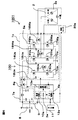
- FIG. 1 is an overall circuit diagram of the drive device and the electric power steering device according to the first embodiment.
- the drive device 1001 according to the first embodiment is provided in the electric power steering device 100, and is configured to drive a steering shaft (not shown) as a driven body.
- the electric power steering device 100 includes a drive device 1001 and sensors 11 such as a torque sensor that detects the steering torque applied to the steering shaft by the driver.
- the electric power steering device 100 detects the steering torque applied to the steering shaft by the driver of the vehicle by the torque sensor in the sensors 11, and generates the assist torque corresponding to the detected steering torque by the drive device 1001. Is configured to assist the driver's steering by adding to the steering shaft.
- the drive device 1001 includes a control unit 1, a motor unit 2 that generates an assist torque as a driving force applied to a steering shaft as a driven body, a first rotation sensor 20a, and a second rotation sensor 20b. ..
- the motor unit 2 includes a first armature winding 2a and a second armature winding 2b that are independent of each other.
- the control unit 1 is composed of a first control unit 1a that controls the current of the first armature winding 2a and a second control unit 1b that controls the current of the second armature winding 2b. There is.
- the circles in the figure indicate the connection terminals provided on the first control unit 1a and the second control unit 1b.
- the first control unit 1a constitutes a first control board 4a as a first control circuit and a first inverter circuit for supplying a current to the first armature winding 2a of the motor unit 2.
- the power module 5a, the first power relay switching element 6a, and the first filter 7a are provided.
- the first power module 5a includes a U-phase upper arm switching element 14Ua and a U-phase lower arm switching element 15Ua connected in series, a V-phase upper arm switching element 14V and a V-phase lower arm switching element 15V connected in series, and a series.
- a three-phase bridge circuit including a connected W-phase upper arm switching element 14Wa and a W-phase lower arm switching element 15Wa is provided.
- the first power module 5a includes a U-phase motor relay switching element 16Ua, a V-phase motor relay switching element 16Va, a W-phase motor relay switching element 16Wa, a U-phase shunt resistor 17Ua, and a V-phase shunt. It includes a resistor 17Va, a W-phase shunt resistor 17Wa, a U-phase smoothing capacitor 18Ua, a V-phase smoothing capacitor 18Va, and a W-phase smoothing capacitor 18Wa.
- the first power module 5a may be entirely molded with a resin, or may be divided into a plurality of modules and each of them may be molded with a resin.
- the switching element 16Ua for the U-phase motor relay, the switching element 16Va for the V-phase motor relay, and the switching for the W-phase motor relay are instructed by the first CPU 3a described later. At least one of the element 16W is turned off, and the connection between the first power module 5a and the first armature winding 2a is disconnected.
- the first control circuit 4a as the first control board is an analog input from the first CPU (Central Processing Unit) 3a as the first arithmetic circuit, the first rotation sensor 20a, and the sensors 11.
- a first input circuit 12a that converts a signal into a digital signal and inputs it to the first CPU 3a, and a first that generates a power supply voltage in the first control board 4a from a battery voltage input from an external battery 8.
- a power supply circuit 10a and a first drive circuit 13a are provided.
- the first drive circuit 13a generates a drive signal based on a command from the first CPU 3a, and includes a U-phase upper arm switching element 14Ua, a U-phase lower arm switching element 15Ua, and a V-phase upper arm switching element 14Va.
- the generated drive signal is given to the V-phase lower arm switching element 15Va, the W-phase upper arm switching element 14Wa, and the W-phase lower arm switching element 15Wa, and the switching elements such as these are opened / closed and controlled to open and close the first power.
- PWM Pulse Width Modulation
- the first filter 7a absorbs noise generated during switching of each switching element of the first power module 5a.
- the first power relay switching element 6a can be used from the first CPU 3a when the first power module 5a fails, when the first armature winding 2a in the motor unit 2 fails, or when the battery 8 fails. It is turned off by the command of, and the connection between the battery 8 and the first power module 5a is cut off.
- the second control unit 1b constitutes a second control board 4b as a second control board and a second inverter circuit that supplies a current to the second armature winding 2b of the motor unit 2.
- the power module 5b, the second power relay switching element 6b, and the second filter 7b are provided.
- the second power module 5b includes a U-phase upper arm switching element 14Ub and a U-phase lower arm switching element 15Ub connected in series, a V-phase upper arm switching element 14Vb and a V-phase lower arm switching element 15Vb connected in series, and a series.
- a three-phase bridge circuit including a connected W-phase upper arm switching element 14Wb and a W-phase lower arm switching element 15Wb is provided.
- the second power module 5b includes a U-phase motor relay switching element 16Ub, a V-phase motor relay switching element 16Vb, a W-phase motor relay switching element 17Wb, a U-phase shunt resistor 17Ub, and a V-phase shunt. It includes a resistor 17Vb, a W-phase shunt resistor 17Wb, a U-phase smoothing capacitor 18Ub, a V-phase smoothing capacitor 18Vb, and a W-phase smoothing capacitor 18Wb.
- the second power module 5b may be entirely molded with a resin, or may be divided into a plurality of modules and each of them may be molded with a resin.
- the switching element 16Ub for the U-phase motor relay, the switching element 16Vb for the V-phase motor relay, and the switching for the W-phase motor relay are instructed by the second CPU 3b described later. At least one of the element 16Wb is turned off, and the connection between the second power module 5b and the second armature winding 2b is disconnected.
- the second control board 4b as the second control board converts the analog signal input from the second CPU 3b as the second arithmetic circuit, the second rotation sensor 20b, and the sensors 11 into a digital signal.
- the drive circuit 13b of 2 is provided.
- the second drive circuit 13b generates a drive signal based on a command from the second CPU 3b, and includes a U-phase upper arm switching element 14Ub, a U-phase lower arm switching element 15Ub, and a V-phase upper arm switching element 14Vb.
- V-phase lower arm switching element 15Vb, W-phase upper arm switching element 14Wb, and W-phase lower arm switching element 15Wb are given a generated drive signal to open / close control of these switching elements to obtain a second power.
- the module 5b by, for example, PWM, the current supplied to the second armature winding 2b of the motor unit 2 is controlled.
- the second filter 7b absorbs noise generated during switching of each switching element of the second power module 5b.
- the second power relay switching element 6b can be used from the second CPU 3b when the second power module 5b fails, when the second armature winding 2b in the motor unit 2 fails, or when the battery 8 fails. It is turned off by the command of, and the connection between the battery 8 and the second power module 5b is cut off.
- the power source + B from the battery 8 mounted on the vehicle is connected to the ground contact portion corresponding to the ground potential of the vehicle.
- the ignition switch 9 By closing the ignition switch 9, power is turned on to the first control unit 1a via the first power supply circuit 10a of the first control board 4a, and at the same time, the second power supply board of the second control circuit 4b is turned on. The power is turned on to the second control unit 1b via the 10b.
- information such as a torque sensor for detecting steering torque mounted near the handle and a speed sensor for detecting the traveling speed of the vehicle is transmitted from the sensors 11 to the first input circuit 12a of the first control unit 1a. Each is input to the second input circuit 12b of the second control unit 1b.
- the information from the sensors 11 is transmitted to the first CPU 3a via the first input circuit 12a of the first control board 4a.
- the first CPU 3a calculates and outputs a current value, which is a control amount for rotating the motor unit 2, from the information.
- the output signal from the first CPU 3a is transmitted to the first power module 5a as the first inverter circuit via the first drive circuit 13a constituting the output circuit. That is, the first drive circuit 13a as an output circuit receives the command signal of the first CPU 3a and outputs the drive signal for driving each switching element of the first power module 5a to each switching element.
- the first power module 5a has the same circuit configuration as the three-phase U-phase winding U1, V-phase winding V1, and W-phase winding W1 of the first armature winding 2a of the motor unit 2. Therefore, the current can be supplied to each phase winding independently.
- the first drive circuit 13a is mounted on the first control board 4a because only a small current flows, but it can also be arranged on the first power module 5a as the first inverter circuit.
- the potential difference between the U-phase shunt resistor 17Ua, the V-phase shunt resistor 17Ba, the W-phase shunt resistor 17Wa, and the voltage of the motor winding terminal are also transmitted to the first input circuit 12a.
- the information is also input to the first CPU 3a.
- the first CPU 3a calculates the difference between the current value calculated based on these input information and the detected value, and performs so-called feedback control to obtain a desired motor current in the first armature winding 2a. It supplies to and assists the steering force.
- the first CPU 3a also outputs a drive signal of the first power relay switching element 6a that operates as a relay that connects or disconnects the power supply + B from the battery 8 and the first power module 5a.
- the current supply to the motor itself can be cut off by the first power relay switching element 6a.
- the U-phase motor relay switching element 16Ua, the V-phase motor relay switching element 16Va, and the W-phase motor relay switching element 16Wa are arranged in the first power module 5a, and the like. Each phase can be cut off by the switching element for the motor relay of.
- the first power supply relay switching element 6a Since the first power supply relay switching element 6a generates heat because a large current flows through it, it can be included in the first power module 5a and configured as a power module as a whole.
- the noise emitted by the PWM control of the first power module 5a can be suppressed by the power supply + B from the battery 8 and the first filter 7a composed of a capacitor and a coil arranged in the vicinity of the ground terminal.
- the first CPU 3a has an abnormality detection function that detects abnormalities in the sensors 11, the first drive circuit 13a, the first power module 5a, the first armature winding 2a, and the like from the input information.
- abnormalities for example, in order to cut off the current supply of only a predetermined phase, the upper arm switching element and the lower arm switching element of the relevant phase and the switching element for the motor relay are detected. Turn off.
- the information from the sensors 11 is transmitted to the second CPU 3b via the second input circuit 12b of the second control circuit 4b.
- the second CPU 3b calculates and outputs a current value, which is a control amount for rotating the motor unit 2, from the information.
- This output signal is transmitted to the second power module 5b as the second inverter circuit via the second drive circuit 13b constituting the output circuit. That is, the second drive circuit 13b as an output circuit receives the command signal of the second CPU 3b and outputs the drive signal for driving each switching element of the second power module 5b to each switching element.
- the second power module 5b has the same circuit configuration for the three-phase U-phase winding U1, V-phase winding V1, and W-phase winding W1 of the motor unit 2, and each phase winding has the same circuit configuration.
- the current can be supplied independently.
- the second drive circuit 13b allows only a small current to flow, it is mounted on the second control circuit 4b, but it can also be arranged on the second power module 5b as the second inverter circuit.
- the potential difference between the U-phase shunt resistor 17Ub, the V-phase shunt resistor 17Vb, the W-phase shunt resistor 17Wb, and the voltage of the motor winding terminal are also transmitted to the second input circuit 12b.
- the information is also input to the second CPU 3b.
- the second CPU 3b calculates the difference between the current value calculated based on these input information and the detected value, and performs so-called feedback control to obtain a desired motor current in the second armature winding 2b. It supplies to and assists the steering force.
- the second CPU 3b also outputs a drive signal of the second power relay switching element 6b that operates as a relay that connects or disconnects the power supply + B from the battery 8 and the second power module 5b.
- the current supply to the motor itself can be cut off by the second power relay switching element 6b.
- the switching element 16Ub for the U-phase motor relay, the switching element 16Vb for the V-phase motor relay, and the switching element 16Wb for the W-phase motor relay are arranged in the second power module 5b. Each phase can be cut off by the switching element for the motor relay of.
- the second power supply relay switching element 6b Since the second power supply relay switching element 6b generates heat because a large current flows through it, it can be included in the second power module 5b and configured as a power module as a whole.
- the noise emitted by the PWM control of the second power module 5b can be suppressed by the power supply + B from the battery 8 and the second filter 7b composed of a capacitor and a coil arranged in the vicinity of the ground terminal.
- the second CPU 3b has an abnormality detection function that detects abnormalities in the sensors 11, the second drive circuit 13b, the second power module 5b, the second armature winding 2b, and the like from the input information.
- an abnormality such as this is detected, for example, in order to cut off the current supply of only a predetermined phase, the upper arm switching element and the lower arm switching element of the phase and the switching for the motor relay Turn off the element.
- the first CPU 3a and the second CPU 3b are connected by a communication line 19 so that information can be exchanged with each other, and when an abnormality is detected, the content of the abnormality is also transmitted to the other party.
- the motor unit 2 is a brushless motor in which two independent first armature windings 2a and a second armature winding 2b of three phases are delta-connected. Since the motor unit 2 is a brushless motor in this way, a first rotation sensor 20a and a second rotation sensor 20b for detecting the rotation position of the rotor are mounted on the drive device 1001. As described above, two sensors, a first rotation sensor 20a and a second rotation sensor 20b, are mounted in order to secure a redundant system, and the rotation information from the first rotation sensor 20a is the first. The rotation information from the second rotation sensor 20b is transmitted to the first input circuit 12a of the control board 4a of 1, and the rotation information from the second rotation sensor 20b is transmitted to the second input circuit 12b of the second control board 4b.
- the motor unit 2 may not be a brushless motor with a three-phase delta connection, may be a star connection, or may be a two-pole, two-pair brushed motor. Further, as for the winding specifications, distributed winding and centralized winding can be adopted as in the conventional device. Further, it may be a tandem motor having so-called two stators. However, the configuration may be such that the desired motor rotation speed and torque can be output regardless of whether the armature winding is only one or the two armature windings cooperate.
- the drive device and the electric power steering device have a configuration in which the network, the connector, the sensor, and the like all have two independent control systems, and are configured to ensure redundancy. Has been done.
- FIG. 2 is a cross-sectional view of the drive device and the electric power steering device according to the first embodiment.
- the drive device 1001 and the electric power steering device 100 according to the first embodiment are roughly classified into a control unit 1 and a motor unit 2.
- the motor unit 2 is a brushless motor in which two independent first armature windings 2a and 2b of three phases are delta-connected, and is a multi-phase winding motor. Is.
- the control unit 1 is arranged so that the extending direction of the axial center of the control unit 1 coincides with the extending direction of the axial center of the motor unit 1, and is fixed to the axial end of the motor unit 2 on the opposite output side. More specifically, the motor unit 2 and the control unit 1 have the same outer diameter dimension, are arranged so as to be aligned on the same axis, are connected to each other, and are integrated.
- the maximum outer diameter of the control unit 2 needs to be formed to be the same as or smaller than the maximum outer diameter of the motor unit 2. Therefore, in the first embodiment, a so-called vertical arrangement structure is adopted in which the main constituent members of the control unit 1 are upright in the direction in which the axis extends, that is, in the direction in which the output shaft of the motor unit 1 extends. ing.
- the motor unit 2 has an output shaft 22 built in a cylindrical motor case 21, a rotor 23 fixed to the output shaft 22, and an inner peripheral surface facing the outer peripheral surface of the rotor 23 via an air gap. It is mainly composed of a stator 24 having a stator 24.
- the first armature winding 2a and the second armature winding 2b described above are wound and arranged on the stator 24.
- the annular wiring portion 26 arranged near the upper part of the drawing with respect to the first armature winding 2a and the second armature winding 2b is a first armature winding 2a and a second armature winding. It is connected to the end of wire 2b.
- the first winding end portion 27a and the second winding end portion 27b penetrate the frame 28 described later and the heat sink 34 described later in the direction in which the axes of the motor unit 1 and the control unit 1 extend from the annular wiring portion 26. It extends.
- first winding end portion 27a is connected to the winding end portion of the first armature winding 2a via the annular wiring portion 26, and the second winding end portion 27b is the annular wiring portion. It is connected to the winding end of the second armature winding 2b via 26.
- the first winding end portion 27a is a winding end portion of the U-phase winding U1 of the first armature winding 2a, a winding end portion of the V-phase winding V1, and a winding of the W-phase winding W1.
- Three conductors, each connected to the end of the wire, are assembled together.
- the second winding end portion 27b is a winding end portion of the U-phase winding U2 of the second armature winding 2b, a winding end portion of the V-phase winding V2, and a winding of the W-phase winding W2.
- Three conductors, each connected to the end of the wire, are assembled together.
- the first winding end portion 27a and the second winding end portion 27b are extended to the vicinity of the outer periphery inside the housing 31 of the control unit 1.
- the rotor 23 has a plurality of pairs of permanent magnets (not shown) constituting field poles arranged on its peripheral surface. Further, a pair of first bearings 29a and a second bearing 29b that rotatably support the output shaft 22 are arranged in the upper portion and the lower portion in the drawing with respect to the rotor 23, respectively.
- the first bearing 29a is arranged in the center of the frame 28 in the vicinity of the control unit 1.
- the frame 28 forms a boundary wall between the motor unit 2 and the control unit 1, and serves as a lid that closes the inside of the motor unit 2.
- the second bearing 29b is fixed to the structure 50 on the output side of the motor unit 2.
- a sensor rotor 30, which will be described later, is fixed to the end of the output shaft 22 on the opposite output side.
- the first rotation sensor 20a and the second rotation sensor 20b are fixed to the inside of the motor case 21 of the motor unit 2 via a gap on the axial end surface of the sensor rotor 30.
- the outside of the control unit 1 is covered with a cylindrical housing 31.
- One end of the housing 31 in the axial direction is coupled to one end in the axial direction on the opposite output side of the motor case 21, and the other end in the axial direction is closed by a disc-shaped housing end wall 311.
- the inner end face and the outer end face of the housing end wall 311 are arranged perpendicular to the axis passing through the axis of the output shaft 22 of the motor unit 2, and the outer end face thereof is connected to the battery 8 as an external power source.
- a first power connector 32a having a first power line 43a and a second power connector 32b having a second power line 43b, and a first signal line 44a connected to the sensors 11 are provided.
- a second signal connector 33b with a first signal connector 33a and a second signal line 44b is provided.
- first filter 7a and a second filter 7b which are relatively large parts, are mounted on the outer end surface of the housing end wall 311.
- the first power supply connector 32a and the second power supply connector 32b are connectors through which a relatively large current of the power supply system flows, and the first signal connector 33a and the second signal connector 33b are relatively small signal systems. It is a connector through which current flows.
- the first power connector 32a and the second power connector 32b of the power supply system, and the first signal connector 33a and the second signal connector 33b of the signal system are put together into one and the outer end surface of the housing end wall 311.
- the power supply system and the signal system may be branched inside the housing 31.
- FIG. 3 is a perspective view of a main part of the drive device and the electric power steering device according to the first embodiment as viewed from the power connector side, and is rotated 90 degrees counterclockwise with respect to FIG. It is shown in the state of.
- a pillar portion 341 having a rectangular columnar cross section in the heat sink 34 is arranged in the central portion inside the housing 31, and as will be described later, in the peripheral portion of the pillar portion 341.
- a first control board 4a, a second control board 4b, a first power module 5a forming a first inverter circuit, a second power module 5b forming a second inverter circuit, and the like are arranged.
- the heat sink 34 is composed of the above-mentioned pillar portion 341 and an annular base portion 342 fixed to one end of the pillar portion 341 in the length direction.
- the pillar portion 341 of the heat sink 34 is arranged in the central portion of the housing 31 so that the length direction is along the axis of the housing 31 of the control unit 1.
- the outer peripheral surface of the base portion 342 of the heat sink 34 is inscribed in the inner peripheral surface of the motor case 21 and is supported by the motor case 21. That is, the heat sink 34 is arranged so that the base portion 342 is fixed to the motor case 21 and the pillar portion 341 cantilevered and supported by the base portion 342 projects into the internal space of the housing 31.
- a sensor rotor 30 fixed to the axial end on the opposite output side of the output shaft 22 is arranged in the inner space of the base portion 342 of the heat sink 34 formed in an annular shape.
- the first rotation sensor 20a and the second rotation sensor 20b mounted on the circuit board 35 are arranged so as to face each other on the surface of the sensor rotor 30 via a gap, and are arranged in a space inside the base portion 342 of the heat sink 34. Has been done.
- the sensor rotor 30 includes one pair or a plurality of pairs of permanent magnets.
- the first rotation sensor 20a and the second rotation sensor 20b which are arranged separately, independently detect a change in the magnetic field from the permanent magnet of the sensor rotor 30 that rotates with the rotation of the output shaft 22, and generate an electric signal. Convert.
- the first rotation sensor 20a and the second rotation sensor 20b may be built in one package.
- FIG. 2 shows a configuration in which the first rotation sensor 20a and the second rotation sensor 20b are incorporated in one package.
- the power supply lines and signal lines of the first rotation sensor 20a and the second rotation sensor 20b are divided into a first control board 4a and a second control board 4b, respectively, via a wiring pattern of the circuit board 35. Be connected.
- the circuit board 35 is arranged so as to be wrapped in the inner peripheral surface of the hollow portion formed in the base portion 342 of the heat sink 34, and is fixed to the base portion 342 of the heat sink 34. Therefore, the surface area of the circuit board 35 is formed smaller than the surface areas of the first control board 4a and the second control board 4b.
- the sensor rotor 30, the first rotation sensor 20a, and the second rotation sensor 20b have been described as being of the magnetic sensor type, they may be other than the magnetic sensor type, for example, a resolver. , Or it may be a hall sensor.
- the first control board 4a is vertically arranged along one side surface of the pillar portion 341 of the heat sink 34 on the long side side.
- the second control board 4b is vertically arranged along the other side surface of the pillar portion 341 of the heat sink 34 on the long side side.
- the first control board 4a and the second control board 4b are vertically arranged so as to face each other via the pillar portion 341 of the heat sink 34.
- the first control board 4a includes the first CPU 3a, the first input circuit 12a, and the first power supply circuit 10a.
- the first drive circuit 13a is mounted, and the second CPU 3b, the second input circuit 12b, the second power supply circuit 10b, and the second drive circuit 13b are mounted on the second control board 4b. ing.
- the U-phase smoothing capacitor 18Ua, the V-phase smoothing capacitor 18Va, and the W-phase smoothing capacitor 18Wa in the first power module 5a are radially outside the control unit 1 with respect to the first control board 4a and are the first. It is arranged vertically in parallel with the control board 4a.
- the W-phase smoothing capacitor 18Wa, the V-phase smoothing capacitor 18Va, and the U-phase smoothing capacitor 18Ua are sequentially stacked vertically from the motor unit 2 side with an interval in the axial direction of the control unit 1 and are arranged vertically with the first power connector 32a. It is arranged so as to sequentially approach the first signal connector 33a.
- the U-phase smoothing capacitor 18Ub, the V-phase smoothing capacitor 18Vb, and the W-phase smoothing capacitor 18Wb in the second power module 5b are radially outside the control unit 1 with respect to the second control board 4b and are second. It is arranged vertically in parallel with the control board 4b.
- the W-phase smoothing capacitor 18Wb, the V-phase smoothing capacitor 18Vb, and the U-phase smoothing capacitor 18Ub are sequentially stacked vertically from the motor unit 2 side with an interval in the axial direction of the control unit 1 and are arranged vertically with the second power connector 32b. It is arranged so as to approach the second signal connector 33b in sequence.
- the pillar portion 341 of the heat sink 34 is arranged at the central portion in the radial direction of the housing 31 of the control unit 1, and the first control board 4a is the length of the pillar portion 341 of the heat sink 34 as described above.
- the second control board 4b is vertically arranged along one side surface on the side side, and the second control board 4b is vertically arranged along the other side surface on the long side side of the pillar portion 341 of the heat sink 34.
- the first power module 5a is vertically arranged along one side surface of the pillar portion 341 of the heat sink 34 on the short side side
- the second power module 5a is arranged along the other side surface of the pillar portion 341 of the heat sink 34 on the short side side.
- Power modules 5b are arranged vertically. Therefore, the first power module 5a and the second power module 5b are arranged so as to face each other via the pillar portion 341 of the heat sink 34.
- first control board 4a and the second control board 4b are arranged as described above, they are separated from each other, and the first power module 5a and the second power module 5b are arranged as described above. Because it is, they are separated from each other.
- the first control board 4a has a shape extending in the radial direction of the control unit 1 from one side surface of the pillar portion 341 of the facing heat sink 34. The reason is that the signal terminal 36a of the first power module 5a and the first control board 4a are connected. Similarly, in order to connect the signal terminal 36b of the second power module 5b and the second control board 4b, the second control board 4b is a control unit from the other side surface of the pillar portion 341 of the facing heat sink 34. It has a shape extending in the direction opposite to that of the first control board 4a on the radial side of 1.
- the first control board 4a and the second control board 4b are arranged point-symmetrically with respect to the radial center of the control unit 1, and the first power is arranged with respect to the radial center of the control unit 1.
- the module 5a and the second power module 5b are arranged point-symmetrically. Therefore, the first winding end portion 27a and the second winding end portion 27b of the motor unit 2 are a set of the first control board 4a and the first power module 5a, and the second control board 4b and the second. It is possible to selectively connect to any set of the two power modules 5b.
- the first winding end portion 27a is connected to the assembly side of the first control board 4a and the first power module 5a, and the second winding end portion 27b is the second. It is connected to the assembly side of the control board 4b and the second power module 5b.
- the first bus bar unit 39a is vertically arranged and attached to one side surface of the pillar portion 341 of the heat sink 34 to which the first control board 4a is attached.
- the first bus bar unit 39a is arranged so as to face the surface of the second control board 4b on the anti-heat sink side.
- the second bus bar unit 39b is arranged so as to face the surface of the first control board 4a on the anti-heat sink side.
- FIG. 4 is a perspective view of the bus bar unit in the drive device and the electric power steering device according to the first embodiment.
- the first bus bar unit 39a and the second bus bar unit 39b are formed in the same shape, and are vertically arranged and attached to one side surface of the pillar portion 341 of the heat sink 34 to which the second control board 4b is attached. As a result, it becomes the first bus bar unit 39a, and when the first control board 4a is vertically arranged and attached to the other side surface of the pillar portion 341 of the heat sink 34, it becomes the second bus bar unit 39b.
- the first bus bar unit 39a includes a first power bus bar 40a, a first grounded bus bar 41a, a first extension terminal 37a, a first power bus bar 40a, and a first grounded bus bar 41a. It is composed of a first bus bar holder 42a for burying and holding a part of the first extension terminal 37a.
- FIG. 5A is a perspective view of the power bus bar in the drive device and the electric power steering device according to the first embodiment.
- a part of the first power bus bar 40a is embedded in the first bus bar holder 42a, and the anti-heat sink side at right angles to the buried portion 400, that is, the first bus bar holder.
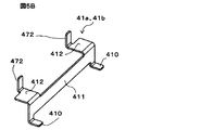
- FIG. 5B is a perspective view of the ground bus bar in the drive device and the electric power steering device according to the first embodiment.
- a part of the grounded bus bar 41a is embedded in the first bus bar holder 42a, and the first grounded bus bar 41a is perpendicular to the heat sink side, that is, the opposite of the bus bar holder 42a.
- a first bent portion 411 that is bent perpendicular to the first surface 45 that is a surface on the heat sink side, and a second bent portion that is bent at a right angle from the first bent portion 411 to the anti-busbar holder side. It has a 412 and a terminal portion 472 that is bent at a right angle from the second bent portion 412 to the anti-heat sink side.
- the side surface of the second bent portion 412 of the first ground bus bar 41a faces the side surface of the second bent portion 402 of the first power bus bar 40a. Further, the side surface of the terminal portion 472 of the first grounded bus bar 41a faces the side surface of the terminal portion 471 of the first power supply bus bar 40a.
- the first extension terminal 37a is composed of three independent conductors, each of which is bent at a right angle in the edgewise direction at the central portion and embedded in the bus bar holder 42a.
- the three conductors of the first extension terminal 37a are from one side of the short side of the bus bar holder 42a to the anti-heat sink side from the embedded central portion, that is, with respect to the first surface 45 of the first bus bar holder 42a.
- extension terminal terminal portion 373 that is bent at a right angle to the anti-heat sink side after being extended from one side surface of the bus bar holder 42a on the long side.
- the side surface of the extension terminal terminal portion 373 of the first extension terminal 37a faces the side surface of the terminal portion 471 of the first power bus bar 40a.
- the first bus bar holder 42a formed of the insulating resin has a W-phase smoothing capacitor 18Wb, a V-phase smoothing capacitor 18Vb, and a U of the first power module 5a on the first surface 45, which is the surface on the anti-heat sink side. It is provided with three storage recesses 46 for arranging the phase smoothing capacitor 18Ub, respectively.
- the second bus bar unit 39b has the same configuration as the first bus bar unit 39a described above, and as shown in FIG. 4, the second power bus bar 40b, the second grounded bus bar 41b, and the second extension terminal. It is composed of 37b, a second power bus bar 40b, a second grounded bus bar 41b, and a second bus bar holder 42b for embedding and holding a part of the second extension terminal 37b.
- the first bus bar unit 39a configured as described above is vertically arranged on the anti-heat sink side of the second control board 4b and fixed to the pillar portion 341 of the heat sink 34.
- the positive electrode side line of the first power supply line 43a from the first power supply connector 32a is connected to the positive electrode side of the first filter 7a (see FIG. 1), and then the first power supply bus bar in the first bus bar unit 39a. It is connected to 40a.
- the terminal portion 471 of the first power bus bar 40a is connected to the positive electrode terminal of the plurality of output terminals 38a of the first power module 5a.
- the terminal portion 472 of the first grounded bus bar 41a in the first bus bar unit 39a is connected to the ground terminal of the plurality of output terminals 38a of the first power module 5a.
- the signal line 44a from the first signal connector 33a is directly connected to the first input circuit 12a of the first control board 4a.
- the three first extension terminals 37a in the first bus bar unit 39a are connected to the U-phase terminal, the V-phase terminal, and the W-phase terminal of the plurality of output terminals 38a of the first power module 5a, respectively.
- the second bent portion 372 of the three first extension terminals 37a is a U-phase winding terminal and a V-phase winding at the first winding end portion 27a extending through the base portion 342 of the heat sink 34. It is connected to the terminal and the W-phase winding terminal respectively.
- the first winding end portion 27a and the second winding end portion 27b, which consist of U-phase, V-phase, and W-phase terminals, are control units for the first control board 4a and the second control board 4b, respectively.
- the output terminals 38a and 38b of the first power module 5a and the second power module 5b are arranged outside the radial direction of the first power module 5a and via the first extension terminal 37a and the second extension terminal 37b, respectively. Be connected.
- the U-phase smoothing capacitor 18Ua, the V-phase smoothing capacitor 18V, and the W-phase smoothing capacitor 18Wa in the first power module 5a are mounted and fixed to the three storage recesses 46 of the first bus bar holder 42a, respectively.
- the width of the first bent portion 401 provided in the first power bus bar 40a and the second power bus bar 40b, respectively, is provided in the first power bus bar 40a and the second power bus bar 40b, respectively. It is formed larger than the width of the terminal portion 471. Further, the widths of the first bent portions 411 provided on the first ground bus bar 41a and the second ground bus bar 41b are provided on the first ground bus bar 41a and the second ground bus bar 41b, respectively. It is formed larger than the width of the terminal portion 472.
- first bent portion 401 of the first power bus bar 40a and the first bent portion 411 of the first grounded bus bar 41a include a U-phase smoothing capacitor 18Ua, a V-phase smoothing capacitor 18V, and a W-phase smoothing capacitor 18Wa.
- a U-phase smoothing capacitor 18Ua Arranged between the first power module 5a and, as is well shown in FIG. 4, the surface of the first bent portion 401 of the first power bus bar 40a and the first ground bus bar 41a.
- the surfaces of the first bent portion 411 are arranged so as to face each other.
- first bent portion 401 of the second power bus bar 40b and the first bent portion 411 of the second grounded bus bar 41b include a U-phase smoothing capacitor 18Ub, a V-phase smoothing capacitor 18Vb, and a W-phase smoothing capacitor 18Wb.
- the surface of the first bent portion 401 of the second power bus bar 40b and the surface of the first bent portion 411 of the second ground bus bar 41b are arranged between the second power module 5b and the second power bus bar 40b. They are arranged so as to face each other.
- first power bus bar 40a and the first ground bus bar 41a either of them may be arranged on the first power module 5a side, and in FIG. 4, the first power bus bar 40a is the first power module 5a. It shows the case where it is arranged on the side.
- first power bus bar 40a is the first power module 5a. It shows the case where it is arranged on the side.
- second power bus bar 40b and the second ground bus bar 41b may be arranged on the second power module 5b side, and in FIG. 4, the second power bus bar 40b is the second power module 5b. It shows the case where it is arranged on the side.
- first bus bar unit 39a including a first power bus bar 40a, a first ground bus bar 41a, and a first bus bar holder 42a is created, and a second power bus bar 40b and a second ground bus bar 41b are formed.
- the production of the second bus bar unit 39b including the second bus bar holder 42b can be performed by using integral molding, press fitting, snap fitting, or the like.
- FIG. 4 shows a case where each copper member is integrally molded and fixed to the first bus bar holder 42a and the second bus bar holder 42b.
- the arrangement and connection relationship of the constituent members of the first control system including the first armature winding 2a and the first control unit 1a in the redundant system have been described above, but the second armature winding has been described.
- the arrangement and connection relationship of the constituent members of the second control system including the 2b and the second control unit 1b are the same as those of the first control system.
- the effects obtained by the drive device 1001 and the electric power steering device 100 according to the first embodiment configured as described above will be described.
- the first control system when the inductance of the first bus bar unit 39a, the first power supply bus bar 40a, and the first grounded bus bar 41a in the drive power supply path to the motor unit 2 increases, the first There is a concern that noise such as surge current or surge voltage may be generated in a plurality of semiconductor elements of the power module 5a, resulting in increased heat generation. Therefore, the surface areas of the first power bus bar 40a and the first ground bus bar 41a are large, and between the first power bus bar 40a and the first ground bus bar 41a and the output terminal 38a of the first power module 5a. The distance needs to be short and wired. The same applies to the second control system.
- the first power bus bar 40a is provided with the first bent portion 401, and the first grounded bus bar 41a is provided with the first bent portion 411.
- the first bent portions 401 and 411 facing each other and embedding a part of the first extension terminal 37a in the first bus bar holder 42a, the first bus bar holder 42a is placed on the first surface 45. It is possible to provide a space in. The same applies to the second control system.
- the U-phase smoothing capacitors 18Ua and V of the first power module can be effectively utilized by effectively utilizing the above-mentioned spaces on the first surface 45 of the first bus bar holder 42a and the first surface 45 of the second bus bar holder 42b.
- the phase smoothing capacitor 18V and the W phase smoothing capacitor 18W, and the U phase smoothing capacitor 18Ub, the V phase smoothing capacitor 18Vb, and the W phase smoothing capacitor 18Wb of the second power module on the outer peripheral side inside the housing 31, It is possible to reduce the size of the product, especially the radial area of the control unit.
- a first bent portion 401 having a width larger than the width of the terminal portion 471 of the first power bus bar 40a is provided, and a first having a width larger than the width of the terminal portion 472 of the first ground bus bar 41a is provided.
- the bent portion 411 By providing the bent portion 411, the surface areas of the first power bus bar 40a and the second power bus bar 40b, and the first ground bus bar 41a and the second ground bus bar 41b are increased, and the inductance of these bus bars is reduced. It becomes possible.
- the first control system by arranging the first power supply bus bar 40a and the first grounded bus bar 41a in the vicinity of the output terminal 38a of the first power module 5a, the U-phase smoothing capacitor 18Ua and the V-phase are arranged.
- the smoothing capacitor 18Va and the W-phase smoothing capacitor 18Wa are arranged on the outer peripheral side inside the housing 31 and arranging the second control system in the same manner, it is possible to increase the thickness of the heat sink 34 and improve the heat dissipation performance. improves.
- the first bent portion 401 of the first power bus bar 40a and the first bent portion 411 of the first ground bus bar 41a are combined with the first control board 4a and the first power module.
- it is mounted on the first control board 4a and the second control board 4b. It is possible to expand the mountable area of the component to be mounted.
- the bending direction of the first bent portions 401 and 411 is set to the anti-heat sink 34 side, so that the radial area of the control unit 1 can be reduced and the first power module 5a can be reduced. It is possible to secure a space for forming a tool required for welding the output terminal 38a of the above and the terminal portions 471, 472, 373 of the first bus bar unit 39a, for example, a chuck tool for arc welding. The same applies to the second control system.
- the electric power steering device is provided with two independent control systems such as the armature winding of the motor and the control unit, but in the second embodiment, the armature winding of the motor There is only one control system such as a wire and a control unit.
- FIG. 6 is an overall circuit diagram of the drive device and the electric power steering device according to the second embodiment.
- the motor unit 2 is a brushless motor in which three-phase armature windings 2a are delta-connected.
- the control unit 1 includes only one control system, has the same configuration as the first control unit 1a or the second control unit 1b of FIG. 1 in the first embodiment, and its operation is also shown in FIG. The operation is almost the same as that of the first control unit 1a or the second control unit 1b.
- the components corresponding to the first control system of FIG. 1 are designated by the reference numerals “a” as in FIG.
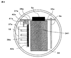
- FIG. 7 is a cross-sectional view of the drive device and the electric power steering device according to the second embodiment.
- the components corresponding to the first system of FIG. 2 are designated by the reference numeral “a” as in FIG.
- other components corresponding to FIG. 2 are designated by the same reference numerals as those in FIG.
- the motor unit 2 includes an armature winding 2a.
- the outer peripheral portion of the control unit 1 is covered with a housing 31, and a power connector 32a for connecting to the battery 8 as an external power source and a plurality of signal connectors 33a for connecting to the sensors 11 are arranged on the axial end surface on the opposite output side.
- a filter 7a or the like which is a relatively large component, is mounted on a surface in the direction perpendicular to the output shaft 22, which is the same surface on which the power connector 32a and the signal connector 33a are arranged.
- a pillar portion 341 of the heat sink 34 is arranged in the center, and a control board 4a, a power module 5a forming an inverter circuit, and the like are arranged around the pillar portion 341.
- the base 342 of the heat sink 34 has a circular shape inscribed in the motor case 21.
- a sensor rotor 30 fixed to the counter-output side end of the output shaft 22 is mounted in the hollow portion at the center of the base portion 342 as in FIG.
- the first power supply line 43a and various first signal lines 44a are also electrically connected to the bus bar and the smoothing capacitors 18Ua, 18Va, 18Wa as in FIG. 2.
- FIG. 8 is a perspective view of a main part as viewed from the power connector side of the drive device and the electric power steering device according to the second embodiment.
- the components corresponding to the first system of FIG. 3 are designated by the reference numerals “a” as in FIG. Further, the parts of the other components corresponding to FIG. 3 are designated by the same reference numerals as those in FIG.
- a pillar portion 341 forming a substantially rectangular parallelepiped of the heat sink 34 is arranged at the center in the radial direction
- a control board 4a is vertically arranged along the peripheral portion thereof, and one side of the pillar portion 341 adjacent thereto is arranged vertically.
- the power module 5a is arranged in close contact with the power module 5a.
- the bus bar unit 39a is arranged on the surface facing the control board 4a via the pillar portion 341.
- the configuration of the bus bar unit 39a is the same as the configuration shown in FIG. 4 described above.
- the terminals U, V, and W of the winding end portion 27 are arranged on the outer peripheral portion in the radial direction with respect to the control board 4a, and are connected to the output terminal 38a of the power module 5a via the bus bar unit 39a.
- the circuit board 35 is arranged in a hollow portion penetrating the base portion 342 of the heat sink 34.
- the power bus bar 40a is provided with the first bent portion 401
- the ground bus bar 41a is provided with the first bent portion 411
- the bent portions 401 and 411 are arranged so as to face each other. Therefore, by effectively utilizing the empty space on the first surface 45 of the bus bar holder 42a and arranging a smoothing capacitor such as a smoothing capacitor 18Ua, the product can be miniaturized, particularly the radial area of the control unit can be miniaturized. Is possible.
- a first bent portion 401 having a width larger than the width of the terminal portion 471 of the power bus bar 40a is provided, and a first bent portion 411 having a width larger than the width of the terminal portion 472 of the ground bus bar 41a is provided.
- the bending direction of the first bent portion 401 of the power bus bar 40a and the first bent portion 411 of the grounding bus bar 41a can be reduced. , It is possible to secure a space for forming a tool necessary for welding the output terminal 38a of the power module 5a and the terminal portions 471, 472, 373 of the bus bar unit 39a.
- the radial area of the control unit 1 can be reduced and the area can be reduced. It is possible to provide a device having high heat dissipation performance.
- FIG. 9 is a perspective view of the bus bar unit in the drive device and the electric power steering device according to the third embodiment.
- the bent portion 49 of the extension terminal 37c of the bus bar unit 39c faces the first bent portion 401 of the power bus bar 40a and the first bent portion 411 of the grounded bus bar 41a. It is characterized in that it is arranged in a manner.
- the extension terminal 37c is not embedded in the busbar holder 42c.
- the busbar unit according to the third embodiment can be used in place of the busbar unit according to the first embodiment or the second embodiment.
- the order of the power bus bar 40a, the ground bus bar 41a, and the extension terminal 37c is not limited to FIG. 9, and can be arbitrarily configured.
- the effects obtained by the drive device equipped with the bus bar unit configured as described above and the electric power steering device are as follows. That is, in the third embodiment, since the extension terminal 37c is not embedded in the bus bar holder 42c, the thickness of the bus bar holder 42c can be reduced and the thickness of the heat sink 34 can be increased accordingly, and the heat dissipation performance is improved. To do. Further, since the contact area between the extension terminal 37c through which a large current flows and the bus bar holder 42c becomes small, it is possible to suppress melting of the bus bar holder 42c when energized.
Landscapes
- Engineering & Computer Science (AREA)
- Power Engineering (AREA)
- Chemical & Material Sciences (AREA)
- Combustion & Propulsion (AREA)
- Transportation (AREA)
- Mechanical Engineering (AREA)
- Microelectronics & Electronic Packaging (AREA)
- Power Steering Mechanism (AREA)
- Inverter Devices (AREA)
Abstract
駆動装置(1001)に設けられた電源バスバー(40a、40b)と接地バスバー(41a、41b)は、パワーモジュール(5a、5b)の出力端子に接続される端子部(471、472)と、バスバーホルダ(42a、42b、42c)の第1の面に対して垂直方向に折り曲げられた折り曲げ部(401、411)とを有し、折り曲げ部(401、411)は、平滑コンデンサ(18Ua、18Va、18Wa)とパワーモジュール(5a、5b)との間に配置され、電源バスバー(40a、40b)と接地バスバー(41a、41b)は、対向して配置されている。
Description
本願は、被駆動体を駆動する駆動装置、および電動パワーステアリング装置に関する。
従来、モータユニットと制御ユニットとが、モータの出力軸に同軸状に軸方向に結合されて一体化された駆動装置があった。このような一体型の駆動装置は、例えば電動パワーステアリング装置の駆動装置として車両に搭載される場合、駆動装置の軸方向の長さは比較的裕度が高いが、車両への取り付け上の規制などにより外径の大きさは制限されることが多く、駆動装置の外径が大きくなると、車両への搭載が困難となることがある。従って、特に、モータに独立した2つの電機子巻線を備えるとともに、制御ユニットにも独立した2つの制御系を備えた電動パワーステアリング装置の場合、パワーモジュール、平滑コンデンサなどの大型部品を制御ユニットの外径を拡大せずに収納するためには、それらを接続するバスバーの形状と配置に工夫を加える必要がある。
特許文献1に開示された従来の駆動装置は、パワーモジュールと制御基板とをモータの軸方向に平行に直立して配置した、いわゆる主要構成部材の縦置き配置方式を採用し、パワーモジュールと外部コネクタとを電気的に接続するためのバスバーを保持したバスバーユニットを、ヒートシンクの面に隣接して設置するように構成している。このように構成された従来の駆動装置によれば、レイアウト設計の自由度が高められるのでバスバーと端子などをより短くすることができ、複数の半導体素子の発熱を好適に抑えることができる。その結果、制御ユニットの外径を車両への取付け上の規制の範囲内に収めることができるとされる。
特許文献1には、バスバーの構造については言及されていない。制御ユニットの小型化、ひいては駆動装置の小型化のためにバスバーの表面積を小さくした場合、モータへの電力の供給路におけるインダクタンスが増大し、パワーモジュールの複数の半導体素子におけるサージ電流若しくはサージ電圧などのノイズの発生を高める原因となり、且つパワーモジュールの複数の半導体素子の発熱が大きくなる懸念がある。一方で、制御ユニットの外径を変えずにバスバーの表面積を大きくした場合、配線経路を確保するために、ヒートシンクの容積を小さくせざるを得ず、パワーモジュールの放熱性能が悪化する懸念がある。
本願は、前述のような課題を解決するための技術を開示するものであり、小型化が可能で、高い放熱性能を備えた駆動装置を提供することを目的とする。
また、本願は、小型化が可能で、高い放熱性能を備えた駆動装置を有する電動パワーステアリング装置を提供することを目的とする。
本願に開示される駆動装置は、
被駆動体を駆動するための駆動力を発生するモータユニットと、
軸心の延びる方向が前記モータユニットの軸心の延びる方向と一致するように配置され、前記モータユニットの反出力側の軸方向端部に固定される制御ユニットと、
を備えた駆動装置であって、
前記制御ユニットは、
前記モータユニットへ電流を供給する複数のスイッチング素子を有するパワーモジュールと、
前記電流を平滑化する平滑コンデンサと、
前記パワーモジュールへの制御信号を出力する演算回路と、
前記演算回路を搭載する制御基板と、
前記パワーモジュールと外部コネクタとを電気的に接続する端子を有するバスバーユニットと、
少なくとも前記パワーモジュールを冷却するヒートシンクと、
を備え、
前記バスバーユニットは、
電源の正極側に接続される電源バスバーと、
前記電源の負極側に接続される接地バスバーと、
前記パワーモジュールの出力端子に接続される延長ターミナルと、
前記電源バスバーと前記接地バスバーと前記延長ターミナルを保持するバスバーホルダと、
を備え、
前記電源バスバーと、前記接地バスバーは、それぞれ、
前記パワーモジュールの出力端子に接続される端子部と、
前記バスバーホルダの第1の面に対して垂直方向に折り曲げられた折り曲げ部と、
を有し、
前記折り曲げ部は、前記平滑コンデンサと前記パワーモジュールとの間に配置され、
前記電源バスバーと、前記接地バスバーは、対向して配置されている、
ことを特徴とするものである。
また、本願に開示される駆動装置は、
互いに独立した第1の電機子巻線と第2の電機子巻線を備え、被駆動体を駆動するための駆動力を発生するモータユニットと、
軸心の延びる方向が前記モータユニットの軸心の延びる方向と一致するように配置され、前記モータユニットの反出力側の軸方向端部に固定された制御ユニットと、
を備えた駆動装置であって、
前記制御ユニットは、
前記第1の電機子巻線に流れる電流を制御する第1の制御ユニットと、
前記第2の電機子巻線に流れる電流を制御する第2の制御ユニットと、
を備え、
前記第1の制御ユニットは、
前記第1の電機子巻線へ電流を供給する複数のスイッチング素子を有する第1のパワーモジュールと、
前記第1の電機子巻線の電流を平滑化する第1の平滑コンデンサと、
前記第1のパワーモジュールへの制御信号を出力する第1の演算回路と、
前記第1の演算回路を搭載する第1の制御基板と、
前記第1のパワーモジュールと外部コネクタとを電気的に接続する端子を有する第1のバスバーユニットと、
を備え、
前記第1のバスバーユニットは、
電源の正極側に接続される第1の電源バスバーと、
前記電源の負極側に接続される第1の接地バスバーと、
前記第1のパワーモジュールの出力端子に接続される第1の延長ターミナルと、
前記第1の電源バスバーと、前記第1の接地バスバーと、前記第1の延長ターミナルを保持する第1のバスバーホルダと、
を備え、
前記第1の電源バスバーと、前記第1の接地バスバーは、それぞれ、
前記第1のパワーモジュールの出力端子に接続される第1の端子部と、
前記第1のバスバーホルダの第1の面に対して垂直方向に折り曲げられた折り曲げ部と、を有し、
前記折り曲げ部は、前記第1の平滑コンデンサと前記第1のパワーモジュールとの間に配置され、
前記第1の電源バスバーと前記第1の接地バスバーは、対向して配置され、
前記第2の制御ユニットは、
前記第2の電機子巻線へ電流を供給する複数のスイッチング素子を有する第2のパワーモジュールと、
前記第2の電機子巻線の電流を平滑化する第2の平滑コンデンサと、
前記第2のパワーモジュールへの制御信号を出力する第2の演算回路と、
前記第2の演算回路を搭載する第2の制御基板と、
前記第2のパワーモジュールと外部コネクタとを電気的に接続する端子を有する第2のバスバーユニットと、
を備え、
前記第2のバスバーユニットは、
電源の正極側に接続される第2の電源バスバーと、
前記電源の負極側に接続される第2の接地バスバーと、
前記第2のパワーモジュールの出力端子に接続される第2の延長ターミナルと、
前記第2の電源バスバーと前記第2の接地バスバーと前記第2の延長ターミナルを保持する第2のバスバーホルダと、
を備え、
前記第2の電源バスバーと、前記第2の接地バスバーは、それぞれ、
前記第2のパワーモジュールの出力端子に接続される第2の端子部と、
前記第2のバスバーホルダの第1の面に対して垂直方向に折り曲げられた折り曲げ部と、を有し、
前記折り曲げ部は、前記第2の平滑コンデンサと前記第2のパワーモジュールとの間に配置され、
前記第2の電源バスバーと前記第2の接地バスバーは、対向して配置され、
少なくとも前記第1のパワーモジュールと前記第2のパワーモジュールを冷却するヒートシンクを備えている、
ことを特徴とするものである。
さらに、本願に開示される電動パワーステアリング装置は、
前記駆動装置のうちの何れかの駆動装置を備え、
車両の運転者がステアリングシャフトに加えるステアリングトルクに対応するアシストトルクを前記駆動装置により発生し、
前記発生したアシストトルクを前記ステアリングシャフトに加えるように構成されている、
ことを特徴とするものである。
前記駆動装置のうちの何れかの駆動装置を備え、
車両の運転者がステアリングシャフトに加えるステアリングトルクに対応するアシストトルクを前記駆動装置により発生し、
前記発生したアシストトルクを前記ステアリングシャフトに加えるように構成されている、
ことを特徴とするものである。
本願に開示される駆動装置によれば、小型化が可能で、高い放熱性能を備えた駆動装置を得ることができる。
また、本願に開示される電動パワーステアリング装置によれば、小型化が可能で、高い放熱性能を備えた駆動装置を有する電動パワーステアリング装置を得ることができる。
以下、本願の実施の形態1および実施の形態2による駆動装置、および電動パワーステアリング装置について、図を参照にして説明する。尚、各図において同一または同様の構成部分については同じ符号を付している。
実施の形態1.
図1は、実施の形態1による駆動装置、および電動パワーステアリング装置の全体回路図である。図1において、実施の形態1による駆動装置1001は、電動パワーステアリング装置100に設けられており、被駆動体としてのステアリングシャフト(図示せず)を駆動するように構成されている。電動パワーステアリング装置100は、駆動装置1001と、運転者がステアリングシャフトに加える操舵トルクを検出するトルクセンサなどのセンサ類11とを備えている。電動パワーステアリング装置100は、車両の運転者がステアリングシャフトに加える操舵トルクをセンサ類11におけるトルクセンサにより検出し、検出した操舵トルクに対応するアシストトルクを駆動装置1001により発生し、発生したアシストトルクをステアリングシャフトに加えることで、運転者の操舵をアシストするように構成されている。
図1は、実施の形態1による駆動装置、および電動パワーステアリング装置の全体回路図である。図1において、実施の形態1による駆動装置1001は、電動パワーステアリング装置100に設けられており、被駆動体としてのステアリングシャフト(図示せず)を駆動するように構成されている。電動パワーステアリング装置100は、駆動装置1001と、運転者がステアリングシャフトに加える操舵トルクを検出するトルクセンサなどのセンサ類11とを備えている。電動パワーステアリング装置100は、車両の運転者がステアリングシャフトに加える操舵トルクをセンサ類11におけるトルクセンサにより検出し、検出した操舵トルクに対応するアシストトルクを駆動装置1001により発生し、発生したアシストトルクをステアリングシャフトに加えることで、運転者の操舵をアシストするように構成されている。
駆動装置1001は、制御ユニット1と、被駆動体としてのステアリングシャフトに加える駆動力としてのアシストトルクを発生するモータユニット2と、第1の回転センサ20aと第2の回転センサ20bを備えている。モータユニット2は、互いに独立した第1の電機子巻線2aと第2の電機子巻線2bを備えている。制御ユニット1は、第1の電機子巻線2aの電流を制御する第1の制御ユニット1aと、第2の電機子巻線2bの電流を制御する第2の制御ユニット1bとにより構成されている。なお図中○印は、第1の制御ユニット1aと、第2の制御ユニット1bに設けられた接続端子を示す。
第1の制御ユニット1aは、第1の制御回路としての第1の制御基板4aと、モータユニット2の第1の電機子巻線2aへ電流を供給する第1のインバータ回路を構成する第1のパワーモジュール5aと、第1の電源リレー用スイッチング素子6aと、第1のフィルタ7aを備えている。
第1のパワーモジュール5aは、直列接続されたU相上アームスイッチング素子14UaとU相下アームスイッチング素子15Ua、直列接続されたV相上アームスイッチング素子14VaとV相下アームスイッチング素子15Va、および直列接続されたW相上アームスイッチング素子14WaとW相下アームスイッチング素子15Wa、からなる三相ブリッジ回路を備えている。
また、第1のパワーモジュール5aは、U相モータリレー用スイッチング素子16Uaと、V相モータリレー用スイッチング素子16Vaと、W相モータリレー用スイッチング素子16Waと、U相シャント抵抗17Uaと、V相シャント抵抗17Vaと、W相シャント抵抗17Waと、U相平滑コンデンサ18Uaと、V相平滑コンデンサ18Vaと、W相平滑コンデンサ18Waと、を備えている。第1のパワーモジュール5aは、全体が樹脂によりモールディングされていてもよく、或いは複数個に分割されてそれぞれが樹脂によりモールディングされていてもよい。
第1の電機子巻線2aのU相巻線U1とV相巻線V1とW相巻線W1とのうちの何れかに短絡故障若しくは断線故障などの故障が生じた場合、又は第1のパワーモジュール5aに何らかの故障が発生した場合には、後述する第1のCPU3aからの指令により、U相モータリレー用スイッチング素子16Uaと、V相モータリレー用スイッチング素子16Vaと、W相モータリレー用スイッチング素子16Waと、のうちの少なくとも何れかをオフとし、第1のパワーモジュール5aと第1の電機子巻線2aとの接続が切り離なされる。
第1の制御基板としての第1の制御回路4aは、第1の演算回路としての第1のCPU(Central Processing Unit)3aと、第1の回転センサ20aとセンサ類11とから入力されたアナログ信号をデジタル信号に変換して第1のCPU3aに入力する第1の入力回路12aと、外部のバッテリ8から入力されたバッテリ電圧から第1の制御基板4a内の電源電圧を生成する第1の電源回路10aと、第1の駆動回路13aを備える。
第1の駆動回路13aは、第1のCPU3aからの指令に基づいて駆動信号を生成し、U相上アームスイッチング素子14Uaと、U相下アームスイッチング素子15Uaと、V相上アームスイッチング素子14Vaと、V相下アームスイッチング素子15Vaと、W相上アームスイッチング素子14Waと、W相下アームスイッチング素子15Waとに、生成した駆動信号を与え、これなどのスイッチング素子を開閉制御し、第1のパワーモジュール5aを、例えばPWM(Pulse Width Modulation)制御することで、モータユニット2の第1の電機子巻線2aに供給する電流を制御する。
第1のフィルタ7aは、第1のパワーモジュール5aの各スイッチング素子のスイッチング時に発生するノイズを吸収する。第1の電源リレー用スイッチング素子6aは、第1のパワーモジュール5aの故障時、若しくはモータユニット2における第1の電機子巻線2aの故障時、或いはバッテリ8の故障時に、第1のCPU3aからの指令によりオフとなり、バッテリ8と第1のパワーモジュール5aとの接続を遮断する。
第2の制御ユニット1bは、第2の制御基板としての第2の制御基板4bと、モータユニット2の第2の電機子巻線2bへ電流を供給する第2のインバータ回路を構成する第2のパワーモジュール5bと、第2の電源リレー用スイッチング素子6bと、第2のフィルタ7bを備えている。
第2のパワーモジュール5bは、直列接続されたU相上アームスイッチング素子14UbとU相下アームスイッチング素子15Ub、直列接続されたV相上アームスイッチング素子14VbとV相下アームスイッチング素子15Vb、および直列接続されたW相上アームスイッチング素子14WbとW相下アームスイッチング素子15Wb、からなる三相ブリッジ回路を備えている。
また、第2のパワーモジュール5bは、U相モータリレー用スイッチング素子16Ubと、V相モータリレー用スイッチング素子16Vbと、W相モータリレー用スイッチング素子17Wbと、U相シャント抵抗17Ubと、V相シャント抵抗17Vbと、W相シャント抵抗17Wbと、U相平滑コンデンサ18Ubと、V相平滑コンデンサ18Vbと、W相平滑コンデンサ18Wbと、を備えている。第2のパワーモジュール5bは、全体が樹脂によりモールディングされていてもよく、或いは複数個に分割されてそれぞれが樹脂によりモールディングされていてもよい。
第2の電機子巻線2bのU相巻線U2とV相巻線V2とW相巻線W2とのうちの何れかに短絡故障若しくは断線故障などの故障が生じた場合、又は第2のパワーモジュール5bに何らかの故障が発生した場合には、後述する第2のCPU3bからの指令により、U相モータリレー用スイッチング素子16Ubと、V相モータリレー用スイッチング素子16Vbと、W相モータリレー用スイッチング素子16Wbと、のうちの少なくとも何れかをオフとし、第2のパワーモジュール5bと第2の電機子巻線2bとの接続が切り離なされる。
第2の制御基板としての第2の制御基板4bは、第2の演算回路としての第2のCPU3bと、第2の回転センサ20bとセンサ類11とから入力されたアナログ信号をデジタル信号に変換して第2のCPU3bに入力する第2の入力回路12bと、外部のバッテリ8から入力されたバッテリ電圧から第2の制御基板4b内の電源電圧を生成する第2の電源回路10bと、第2の駆動回路13bを備える。
第2の駆動回路13bは、第2のCPU3bからの指令に基づいて駆動信号を生成し、U相上アームスイッチング素子14Ubと、U相下アームスイッチング素子15Ubと、V相上アームスイッチング素子14Vbと、V相下アームスイッチング素子15Vbと、W相上アームスイッチング素子14Wbと、W相下アームスイッチング素子15Wbとに、生成した駆動信号を与え、これなどのスイッチング素子を開閉制御し、第2のパワーモジュール5bを、例えばPWM制御することで、モータユニット2の第2の電機子巻線2bに供給する電流を制御する。
第2のフィルタ7bは、第2のパワーモジュール5bの各スイッチング素子のスイッチング時に発生するノイズを吸収する。第2の電源リレー用スイッチング素子6bは、第2のパワーモジュール5bの故障時、若しくはモータユニット2における第2の電機子巻線2bの故障時、或いはバッテリ8の故障時に、第2のCPU3bからの指令によりオフとなり、バッテリ8と第2のパワーモジュール5bとの接続を遮断する。
以上のように構成された実施の形態1による駆動装置1001を備えた電動パワーステアリング装置100において、車両に搭載されたバッテリ8からの電源+Bと、車両の接地電位に相当する接地部位に接続される。イグニッションスイッチ9を閉じることにより、第1の制御基板4aの第1の電源回路10aを介して第1の制御ユニット1aに電源が投入され、同時に、第2の制御回路4bの第2の電源基板10bを介して第2の制御ユニット1bに電源が投入される。
さらに、例えばハンドルの近傍に搭載された操舵トルクを検出するトルクセンサ、車両の走行速度を検出する速度センサなどの情報がセンサ類11から、第1の制御ユニット1aの第1の入力回路12aと第2の制御ユニット1bの第2の入力回路12bに、それぞれ入力される。
センサ類11からの情報は、第1の制御基板4aの第1の入力回路12aを介して第1のCPU3aに伝達される。第1のCPU3aは、それらの情報からモータユニット2を回転させるための制御量である電流値を演算して出力する。第1のCPU3aからの出力信号は出力回路を構成する第1の駆動回路13aを介し第1のインバータ回路としての第1のパワーモジュール5aへ伝達される。すなわち、出力回路としての第1の駆動回路13aは、第1のCPU3aの指令信号を受け、第1のパワーモジュール5aの各スイッチング素子を駆動する駆動信号を各スイッチング素子へ出力する。第1のパワーモジュール5aは、モータユニット2の第1の電機子巻線2aの3相のU相巻線U1、V相巻線V1、W相巻線W1に対して同一の回路構成を有しており、各相巻線に独立に電流供給を行なうことができる。
第1の駆動回路13aは小電流しか流れないため第1の制御基板4aに装着されているが、第1のインバータ回路としての第1のパワーモジュール5aに配置することもできる。
また、U相シャント抵抗17Uaと、V相シャント抵抗17Vaと、W相シャント抵抗17Waの両端間の電位差、及び、例えばモータ巻線端子の電圧なども第1の入力回路12aに伝達され、これらの情報も第1のCPU3aに入力される。第1のCPU3aは、入力されたこれらの情報に基づいて演算した電流値と検出値との差異を演算し、いわゆるフィードバック制御を行うことで、所望のモータ電流を第1の電機子巻線2aに供給し、操舵力をアシストする。さらに、第1のCPU3aは、バッテリ8からの電源+Bと第1のパワーモジュール5aとの接続又は遮断を行なうリレーとして作動する第1の電源リレー用スイッチング素子6aの駆動信号も出力しており、この第1の電源リレー用スイッチング素子6aによりモータ自体への電流供給を遮断することができる。
さらに、前述したようにU相モータリレー用スイッチング素子16Uaと、V相モータリレー用スイッチング素子16Vaと、W相モータリレー用スイッチング素子16Waが第1のパワーモジュール5aに配設されており、これなどのモータリレー用スイッチング素子により各相をそれぞれ遮断することができる。
なお、第1の電源リレー用スイッチング素子6aは、大電流が流れるため発熱を伴うので、第1のパワーモジュール5aに包含させて、全体としてパワーモジュールとして構成することもできる。第1のパワーモジュール5aのPWM制御により放出されるノイズは、バッテリ8からの電源+Bと接地端子の近傍に配置されたコンデンサとコイルからなる第1のフィルタ7aにより抑制することができる。
第1のCPU3aは、入力された各情報から、センサ類11のほか、第1の駆動回路13a、第1のパワーモジュール5a、第1の電機子巻線2aなどの異常を検出する異常検出機能を有し、これらの異常を検出した場合、その異常に応じて、例えば所定の相のみの電流供給を遮断するために、当該相の上アームスイッチング素子及び下アームスイッチング素子とモータリレー用スイッチング素子をオフにする。あるいは、電源自体を元から遮断するために第1の電源リレー用スイッチング素子6aをオフすることも可能である。
一方、センサ類11からの情報は、第2の制御回路4bの第2の入力回路12bを介して第2のCPU3bに伝達される。第2のCPU3bは、それらの情報からモータユニット2を回転させるための制御量である電流値を演算して出力する。この出力信号は出力回路を構成する第2の駆動回路13bを介し第2のインバータ回路としての第2のパワーモジュール5bへ伝達される。すなわち、出力回路としての第2の駆動回路13bは、第2のCPU3bの指令信号を受け、第2のパワーモジュール5bの各スイッチング素子を駆動する駆動信号を各スイッチング素子へ出力する。第2のパワーモジュール5bは、モータユニット2の3相のU相巻線U1、V相巻線V1、W相巻線W1に対して同一の回路構成を有しており、各相巻線に独立に電流供給を行なうことができる。
第2の駆動回路13bは小電流しか流れないため、第2の制御回路4bに装着されているが、第2のインバータ回路としての第2のパワーモジュール5bに配置することもできる。
また、U相シャント抵抗17Ubと、V相シャント抵抗17Vbと、W相シャント抵抗17Wbの両端間の電位差、及び、例えばモータ巻線端子の電圧なども第2の入力回路12bに伝達され、これらの情報も第2のCPU3bに入力される。第2のCPU3bは、入力されたこれらの情報に基づいて演算した電流値と検出値との差異を演算し、いわゆるフィードバック制御を行うことで、所望のモータ電流を第2の電機子巻線2bに供給し、操舵力をアシストする。さらに、第2のCPU3bは、バッテリ8からの電源+Bと第2のパワーモジュール5bとの接続又は遮断を行なうリレーとして作動する第2の電源リレー用スイッチング素子6bの駆動信号も出力しており、この第2の電源リレー用スイッチング素子6bによりモータ自体への電流供給を遮断することができる。
さらに、前述したようにU相モータリレー用スイッチング素子16Ubと、V相モータリレー用スイッチング素子16Vbと、W相モータリレー用スイッチング素子16Wbが第2のパワーモジュール5bに配設されており、これなどのモータリレー用スイッチング素子により各相をそれぞれ遮断することができる。
なお、第2の電源リレー用スイッチング素子6bは、大電流が流れるため発熱を伴うので、第2のパワーモジュール5bに包含させて、全体としてパワーモジュールとして構成することもできる。第2のパワーモジュール5bのPWM制御により放出されるノイズは、バッテリ8からの電源+Bと接地端子の近傍に配置されたコンデンサとコイルからなる第2のフィルタ7bにより抑制することができる。
第2のCPU3bは、入力された各情報から、センサ類11のほか、第2の駆動回路13b、第2のパワーモジュール5b、第2の電機子巻線2bなどの異常を検出する異常検出機能を有し、これなどの異常を検出した場合、その異常に応じて、例えば所定の相のみの電流供給を遮断するために、当該相の上アームスイッチング素子及び下アームスイッチング素子とモータリレー用スイッチング素子をオフにする。あるいは、電源自体を元から遮断するために第2の電源リレー用スイッチング素子6bをオフすることも可能である。
第1のCPU3aと第2のCPU3bは,互いに情報を授受できるように通信ライン19により接続されており、異常検出した場合、その異常の内容も含めて相手方に送信するように構成されている。
モータユニット2は、3相の2つの独立した第1の電機子巻線2aと第2の電機子巻線2bがそれぞれデルタ結線されたブラシレスモータである。モータユニット2が、このようにブラシレスモータであるため、ロータの回転位置を検出するための第1の回転センサ20aと第2の回転センサ20bが駆動装置1001に搭載されている。冗長系を確保するために、前述したように、第1の回転センサ20aと第2の回転センサ20bの2つのセンサがそれぞれ搭載されており、第1の回転センサ20aからの回転情報は、第1の制御基板4aの第1の入力回路12aに伝達され、第2の回転センサ20bからの回転情報は、第2の制御基板4bの第2の入力回路12bに伝達される。
なお、モータユニット2は、3相デルタ結線のブラシレスモータでなくても、スター結線であってもよく、あるいは2極2対のブラシ付きモータであってもよい。また、巻線仕様は従来の装置と同様に、分布巻き、集中巻きも採用することができる。さらに、いわゆる2個のステータを有するタンデムモータであってもよい。ただし、1つの電機子巻線のみであっても、2つ電機子巻線の協働であっても、所望のモータ回転数、トルクを出力できる構成であればよい。
以上述べたように、実施の形態1による駆動装置、および電動パワーステアリング装置は、回路網、コネクタ、センサなどがすべて独立した2つの制御系を有する構成であり、冗長性を確保するように構成されている。
図2は、実施の形態1による駆動装置、および電動パワーステアリング装置の断面図である。図2において、実施の形態1による駆動装置1001、および電動パワーステアリング装置100は、大別すると、制御ユニット1と、モータユニット2とから構成されている。モータユニット2は、前述のように、3相の2つの独立した第1の電機子巻線2aと第2の電機子巻線2bがそれぞれデルタ結線されたブラシレスモータであり、多相巻線モータである。制御ユニット1は、その軸心の延びる方向がモータユニット1の軸心の延びる方向と一致するように配置され、モータユニット2の反出力側の軸方向端部に固定されている。より具体的には、モータユニット2と制御ユニット1は、同一の外径寸法を有し、且つ同一の軸線上に整列するように配置されて相互に結合されて一体化されている。
このようにモータユニット2と制御ユニット1とを一体化した駆動装置1001では、制御ユニット2の最大外形は、モータユニット2の最大外径と同などか、又は小さく形成されている必要がある。そこで、実施の形態1では、制御ユニット1の主要な構成部材を、軸心の延びる方向、すなわちモータユニット1の出力軸の延びる方向と平行に直立させた、いわゆる縦置き配置の構造を採用している。
まず、モータユニット2の構成について図2を用いて説明する。モータユニット2は、円筒形状のモータケース21に内蔵された出力軸22と、出力軸22に固定されたロータ23と、ロータ23の外周面に対してエアギャップを介して対向する内周面を有するステータ24とから主に構成されている。
ステータ24には、前述の第1の電機子巻線2aと第2の電機子巻線2bが巻装されて配置される。第1の電機子巻線2aと第2の電機子巻線2bに対して図の上部の近傍に配置された環状配線部26は、第1の電機子巻線2aと第2の電機子巻線2bの端部に接続されている。第1の巻線端部27aと第2の巻線端部27bは、環状配線部26からモータユニット1および制御ユニット1の軸線の延びる方向に、後述のフレーム28と後述のヒートシンク34を貫通して延びている。ここで、第1の巻線端部27aは、環状配線部26を介して第1の電機子巻線2aの巻線端部に接続され、第2の巻線端部27bは、環状配線部26を介して第2の電機子巻線2bの巻線端部に接続されている。
第1の巻線端部27aは、第1の電機子巻線2aのU相巻線U1の巻線端部と、V相巻線V1の巻線端部と、W相巻線W1の巻線端部とに夫々接続された3本の導体がまとめられて構成されている。第2の巻線端部27bは、第2の電機子巻線2bのU相巻線U2の巻線端部と、V相巻線V2の巻線端部と、W相巻線W2の巻線端部とに夫々接続された3本の導体がまとめられて構成されている。第1の巻線端部27aと第2の巻線端部27bは、制御ユニット1のハウジング31の内部の外周付近へ延伸されている。
ロータ23は、その周面に界磁極を構成する永久磁石(図示せず)が複数対配置されている。また、出力軸22を回転自在に支持する一対の第1の軸受29aと第2の軸受29bが、ロータ23に対して図の上方部と下方部にそれぞれ配置されている。第1の軸受29aは制御ユニット1の近傍でフレーム28の中央部に配置されている。フレーム28は、モータユニット2と制御ユニット1との境界壁をなし、モータユニット2の内部を閉塞する蓋の役目をなしている。第2の軸受29bは、モータユニット2の出力側の構造体50に固定されている。
出力軸22の反出力側の端部には、後述するセンサロータ30が固定されている。センサロータ30の軸方向の端面にギャップを介して第1の回転センサ20aと第2の回転センサ20bがモータユニット2のモータケース21の内部に固定されている。
次に、制御ユニット1の構成について説明する。制御ユニット1は、外側を円筒形のハウジング31で覆われている。ハウジング31は、軸方向の一端がモータケース21の反出力側の軸方向の一端に結合され、軸方向の他端が円板状のハウジング端壁311により閉塞されている。ハウジング端壁311の内側端面と外側端面は、モータユニット2の出力軸22の軸心を通る軸線に対して垂直に配置されており、その外側端面には、外部電源としてのバッテリ8に接続される第1の電源ライン43aを備えた第1の電源コネクタ32aおよび第2の電源ライン43bを備えた第2の電源コネクタ32bと、センサ類11に接続される第1の信号ライン44aを備えた第1の信号コネクタ33aおよび第2の信号ライン44bを備えた第2の信号コネクタ33bが設けられている。
また、ハウジング端壁311の外側端面には、比較的大型部品である第1のフィルタ7aと、第2のフィルタ7bが搭載されている。第1の電源コネクタ32aと、第2の電源コネクタ32bは、電源系の比較的大電流が流れるコネクタであり、第1の信号コネクタ33aと第2の信号コネクタ33bは、信号系の比較的小電流が流れるコネクタである。なお、電源系の第1の電源コネクタ32aと第2の電源コネクタ32b、および信号系の第1の信号コネクタ33aと第2の信号コネクタ33bを、1つにまとめてハウジング端壁311の外側端面に配置し、ハウジング31の内部で電源系と信号系を分岐するようにしてもよい。
図3は、実施の形態1による駆動装置、および電動パワーステアリング装置を電源コネクタ側から見た要部透視図であって、図2に対して軸心を中心として反時計方向に90度回転させた状態で示している。図2及び図3に示すように、ハウジング31の内部の中央部に、ヒートシンク34における断面が長方形の柱状に形成された柱部341が配置され、柱部341の周辺部に、後述するように第1の制御基板4a、第2の制御基板4b、第1のインバータ回路をなす第1のパワーモジュール5a、第2のインバータ回路をなす第2のパワーモジュール5bなどが配置されている。
ヒートシンク34は、前述の柱部341と、この柱部341の長さ方向の一方の端部に固定された環状の基部342とから構成されている。ヒートシンク34の柱部341は、長さ方向が制御ユニット1のハウジング31の軸線に沿うように、ハウジング31の中央部に配置されている。ヒートシンク34の基部342は、その外周面がモータケース21の内周面に内接してモータケース21に支持されている。すなわち、ヒートシンク34は、その基部342がモータケース21に固定され、基部342に片持ち支持された柱部341がハウジング31の内部空間に突出するように配置されている。
環状に形成されたヒートシンク34の基部342の内側空間部には、前述の出力軸22の反出力側の軸方向の端部に固定されたセンサロータ30が配置されている。回路基板35に搭載された第1の回転センサ20aと第2の回転センサ20bは、センサロータ30の表面に間隙を介して対向して配置され、ヒートシンク34の基部342の内側の空間部に配置されている。
センサロータ30は、1対、又は複数対の永久磁石を備えている。分離して配置された第1の回転センサ20aと第2の回転センサ20bは、出力軸22の回転とともに回転するセンサロータ30の永久磁石からの磁界の変化をそれぞれ独立に検出して電気信号に変換する。なお、第1の回転センサ20aと第2の回転センサ20bは、1つのパッケージに内蔵されていてもよい。図2は、第1の回転センサ20aと第2の回転センサ20bが、1つのパッケージに内蔵された構成を示している。
第1の回転センサ20aと第2の回転センサ20bのそれぞれの電源ラインおよび信号ラインは、回路基板35の配線パターンを介して、第1の制御基板4aと第2の制御基板4bにそれぞれ分かれて接続される。回路基板35は、ヒートシンク34の基部342に形成された中空部の内周面に包み込まれるように配置されて、ヒートシンク34の基部342に固定される。そのため、回路基板35の表面積は、第1の制御基板4aと第2の制御基板4bの表面積と比較して小さく形成されている。
なお、センサロータ30と、第1の回転センサ20aと、第2の回転センサ20bは、磁気センサタイプであるとして説明したが、磁気センサタイプ以外であってもよく、例えばレゾルバであってもよく、あるいはホールセンサであってもよい。
第1の制御基板4aは、ヒートシンク34の柱部341の長辺側の一方の側面に沿って縦置き配置されている。第2の制御基板4bは、ヒートシンク34の柱部341の長辺側の他方の側面に沿って縦置き配置されている。このように、第1の制御基板4aと第2の制御基板4bは、ヒートシンク34の柱部341を介して対向するように縦置き配置されている。なお、図2と図3には図示されていないが、第1の制御基板4aには前述したように、第1のCPU3aと、第1の入力回路12aと、第1の電源回路10aと、第1の駆動回路13aが搭載され、第2の制御基板4bには、第2のCPU3bと、第2の入力回路12bと、第2の電源回路10bと、第2の駆動回路13bが搭載されている。
第1のパワーモジュール5aにおける、U相平滑コンデンサ18Uaと、V相平滑コンデンサ18Vaと、W相平滑コンデンサ18Waは、第1の制御基板4aに対して制御ユニット1の径方向外側で且つ第1の制御基板4aと平行に縦置き配置されている。W相平滑コンデンサ18Waと、V相平滑コンデンサ18Vaと、U相平滑コンデンサ18Uaは、制御ユニット1の軸方向に間隔を介してモータユニット2側から順次縦積み配置され、第1の電源コネクタ32aと第1の信号コネクタ33aに順次近づくように配置されている。
第2のパワーモジュール5bにおける、U相平滑コンデンサ18Ubと、V相平滑コンデンサ18Vbと、W相平滑コンデンサ18Wbは、第2の制御基板4bに対して制御ユニット1の径方向外側で且つ第2の制御基板4bと平行に縦置き配置されている。W相平滑コンデンサ18Wbと、V相平滑コンデンサ18Vbと、U相平滑コンデンサ18Ubは、制御ユニット1の軸方向に間隔を介してモータユニット2側から順次縦積み配置され、第2の電源コネクタ32bと第2の信号コネクタ33bに順次近づくように配置されている。
図3に示すように、制御ユニット1のハウジング31の径方向の中央部に、ヒートシンク34の柱部341が配置され、前述のように第1の制御基板4aがヒートシンク34の柱部341の長辺側の一方の側面に沿って縦置き配置され、第2の制御基板4bがヒートシンク34の柱部341の長辺側の他方の側面に沿って縦置き配置されている。そして、ヒートシンク34の柱部341の短辺側の一方の側面に沿って第1のパワーモジュール5aが縦置き配置され、ヒートシンク34の柱部341の短辺側の他方の側面に沿って第2のパワーモジュール5bが縦置き配置されている。したがって、第1のパワーモジュール5aと第2のパワーモジュール5bは、ヒートシンク34の柱部341を介して対向するように配置されている。
第1の制御基板4aと第2の制御基板4bは、前述のように配置されているので互いに分離独立され、また第1のパワーモジュール5aと第2のパワーモジュール5bは、前述のように配置されているので互いに分離独立されている。
第1の制御基板4aは、対向するヒートシンク34の柱部341の一方の側面から制御ユニット1の径方向側に延びた形状を有している。その理由は、第1のパワーモジュール5aの信号端子36aと第1の制御基板4aとを接続するためである。同様に、第2のパワーモジュール5bの信号端子36bと第2の制御基板4bとを接続するために、第2の制御基板4bは、対向するヒートシンク34の柱部341の他方の側面から制御ユニット1の径方向側に、第1の制御基板4aとは逆方向に延びた形状を有している。
制御ユニット1の径方向の中心に対して、第1の制御基板4aと第2の制御基板4bは点対称に配置され、また、制御ユニット1の径方向の中心に対して、第1のパワーモジュール5aと第2のパワーモジュール5bは点対称に配置されている。したがって、モータユニット2の第1の巻線端部27aと第2の巻線端部27bは、第1の制御基板4aと第1のパワーモジュール5aの組と、第2の制御基板4bと第2のパワーモジュール5bの組との、何れの組にも選択的に接続することが可能である。ただし、実施の形態1では、第1の巻線端部27aは第1の制御基板4aと第1のパワーモジュール5aの組側に接続され、第2の巻線端部27bは、第2の制御基板4bと第2のパワーモジュール5bの組側に接続されている。
第1のバスバーユニット39aは、第1の制御基板4aが取り付けられたヒートシンク34の柱部341の一方の側面に縦置き配置されて取り付けられている。第1のバスバーユニット39aは、第2の制御基板4bの反ヒートシンク側の表面に対向して配置されている。また、第2のバスバーユニット39bは、第1の制御基板4aの反ヒートシンク側の表面に対向して配置されている。
図4は、実施の形態1による駆動装置、および電動パワーステアリング装置における、バスバーユニットの斜視図である。第1のバスバーユニット39aと第2のバスバーユニット39bは、同一形状に形成されており、第2の制御基板4bが取り付けられたヒートシンク34の柱部341の一方の側面に縦置き配置されて取り付けられることで第1のバスバーユニット39aとなり、第1の制御基板4aが取り付けられたヒートシンク34の柱部341の他方の側面に縦置き配置されて取り付けられることで第2のバスバーユニット39bとなる。
図4において、第1のバスバーユニット39aは、第1の電源バスバー40aと、第1の接地バスバー41aと、第1の延長ターミナル37aと、第1の電源バスバー40aと第1の接地バスバー41aと第1の延長ターミナル37aの一部の部位を埋設してこれらを保持する第1のバスバーホルダ42aとから構成されている。
図5Aは、実施の形態1による駆動装置、および電動パワーステアリング装置における、電源バスバーの斜視図である。図4および図5Aにおいて、第1の電源バスバー40aは、一部の部位400が第1のバスバーホルダ42aに埋設され、この埋設された部位400から直角に反ヒートシンク側、即ち第1のバスバーホルダ42aの反ヒートシンク側の面である第1の面45に対して垂直に折り曲げられた第1の折り曲げ部401と、この第1の折り曲げ部401から直角に反バスバーホルダ側に折り曲げられた第2の折り曲げ部402と、この第2の折り曲げ部402から直角に反ヒートシンク側に折り曲げられた端子部471を有する。
図5Bは、実施の形態1による駆動装置、および電動パワーステアリング装置における、接地バスバーの斜視図である。図4および図5Bにおいて、第1の接地バスバー41aは、一部の部位410が第1のバスバーホルダ42aに埋設され、この埋設された部位410から直角に反ヒートシンク側、即ちバスバーホルダ42aの反ヒートシンク側に面である第1の面45に対して垂直に折り曲げられた第1の折り曲げ部411と、この第1の折り曲げ部411から直角に反バスバーホルダ側に折り曲げられた第2の折り曲げ部412と、この第2の折り曲げ部412から直角に反ヒートシンク側に折り曲げられた端子部472を有する。
第1の接地バスバー41aの第2の折り曲げ部412の側面が、第1の電源バスバー40aの第2の折り曲げ部402の側面と対向している。また、第1の接地バスバー41aの端子部472の側面が、第1の電源バスバー40aの端子部471の側面と対向している。
第1の延長ターミナル37aは、3本の独立した導体からなり、これなどの3本の導体はそれぞれ中央部で直角にエッジワイズ方向に折り曲げられてバスバーホルダ42aに埋設されている。第1の延長ターミナル37aの3本の導体は、埋設された中央部からバスバーホルダ42aの短辺側の一方の側面から反ヒートシンク側、即ち第1のバスバーホルダ42aの第1の面45に対して垂直に折り曲げられた第1の折り曲げ部371と、この第1の折り曲げ部371から第1のバスバーホルダ42a側に直角に折り曲げられた第2の折り曲げ部372と、埋設された中央部から第1のバスバーホルダ42aの長辺側の一方の側面から延出された後に、反ヒートシンク側に直角に折り曲げられた延長ターミナル端子部373とを有する。第1の延長ターミナル37aの延長ターミナル端子部373の側面は、第1の電源バスバー40aの端子部471の側面と対向している。
絶縁樹脂により形成された第1のバスバーホルダ42aは、反ヒートシンク側の表面である第1の面45に、第1のパワーモジュール5aのW相平滑コンデンサ18Wbと、V相平滑コンデンサ18Vbと、U相平滑コンデンサ18Ubとを夫々配置させるための3個の収納凹部46を備えている。
第2のバスバーユニット39bは、前述の第1のバスバーユニット39aと同一構成であり、図4に示すように、第2の電源バスバー40bと、第2の接地バスバー41bと、第2の延長ターミナル37bと、第2の電源バスバー40bと第2の接地バスバー41bと第2の延長ターミナル37bの一部の部位を埋設してこれらを保持する第2のバスバーホルダ42bとから構成されている。
以上のように構成された第1のバスバーユニット39aは、図2及び図3に示すように、第2の制御基板4bの反ヒートシンク側に縦置き配置されてヒートシンク34の柱部341に固定される。第1の電源コネクタ32aからの第1の電源ライン43aの正極側ラインは、第1のフィルタ7a(図1参照)の正極側に接続され後、第1のバスバーユニット39aにおける第1の電源バスバー40aに接続される。第1の電源バスバー40aの端子部471は、第1のパワーモジュール5aの複数の出力端子38aのうちの正極端子に接続される。第1のバスバーユニット39aにおける第1の接地バスバー41aの端子部472は、第1のパワーモジュール5aの複数の出力端子38aのうちの接地端子に接続される。第1の信号コネクタ33aからの信号ライン44aは、第1の制御基板4aの第1の入力回路12aに直接接続される。
第1のバスバーユニット39aにおける3本の第1の延長ターミナル37aは、第1のパワーモジュール5aの複数の出力端子38aのうちのU相端子とV相端子とW相端子にそれぞれ接続される。3本の第1の延長ターミナル37aの第2の折り曲げ部372は、ヒートシンク34の基部342を貫通して延出された第1の巻線端部27aにおけるU相巻線端子とV相巻線端子とW相巻線端子に夫々接続される。U相、V相、W相の端子からなる第1の巻線端部27aと第2の巻線端部27bは、それぞれ第1の制御基板4aと第2の制御基板4bに対して制御ユニット1の径方向の外側に配置されており、それぞれ第1の延長ターミナル37aと第2の延長ターミナル37bを介して、第1のパワーモジュール5aと第2のパワーモジュール5bの出力端子38a、38bと接続される。
第1のパワーモジュール5aにおける、U相平滑コンデンサ18Uaと、V相平滑コンデンサ18Vaと、W相平滑コンデンサ18Waは、第1のバスバーホルダ42aの3つの収納凹部46にそれぞれ搭載されて固定される。
ここで、第1の電源バスバー40aと第2の電源バスバー40bとにそれぞれ設けられた第1の折り曲げ部401の幅は、第1の電源バスバー40aと第2の電源バスバー40bとにそれぞれ設けられた端子部471の幅よりも大きく形成されている。また、第1の接地バスバー41aと第2の接地バスバー41bとにそれぞれ設けられた第1の折り曲げ部411の幅は、第1の接地バスバー41aと第2の接地バスバー41bとにそれぞれ設けられた端子部472の幅よりも大きく形成されている。
また、第1の電源バスバー40aにおける第1の折り曲げ部401と第1の接地バスバー41aの第1の折り曲げ部411は、U相平滑コンデンサ18UaとV相平滑コンデンサ18VaとW相平滑コンデンサ18Waと、第1のパワーモジュール5aとの間に配置され、且つ、図4に良く示されているように、第1の電源バスバー40aにおける第1の折り曲げ部401の面と、第1の接地バスバー41aの第1の折り曲げ部411の面は、対向するように配置されている。
同様に、第2の電源バスバー40bにおける第1の折り曲げ部401と第2の接地バスバー41bの第1の折り曲げ部411は、U相平滑コンデンサ18UbとV相平滑コンデンサ18VbとW相平滑コンデンサ18Wbと、第2のパワーモジュール5bとの間に配置され、且つ、第2の電源バスバー40bにおける第1の折り曲げ部401の面と、第2の接地バスバー41bの第1の折り曲げ部411の面は、対向するように配置されている。
なお、第1の電源バスバー40aと第1の接地バスバー41aのうち、何れが第1のパワーモジュール5a側に配置されても良く、図4では第1の電源バスバー40aが第1のパワーモジュール5a側に配置されている場合を示している。同様に、第2の電源バスバー40bと第2の接地バスバー41bのうち、どちらが第2のパワーモジュール5b側に配置されても良く、図4では第2の電源バスバー40bが第2のパワーモジュール5b側に配置されている場合を示している。
また、第1の電源バスバー40aと第1の接地バスバー41aと第1のバスバーホルダ42aとからなる第1のバスバーユニット39aの作成、および、第2の電源バスバー40bと第2の接地バスバー41bと第2のバスバーホルダ42bとからなる第2のバスバーユニット39bの作成は、一体成形、圧入、スナップフィットなどを用いて行うことができる。図4は、第1のバスバーホルダ42a、および第2のバスバーホルダ42bに、各銅製部材を一体成形で固定して作成した場合を示す。
以上、冗長系システムにおける、第1の電機子巻線2aと第1の制御ユニット1aとからなる第1の制御系の構成部材の配置と接続関係について述べたが、第2の電機子巻線2bと第2の制御ユニット1bとからなる第2の制御系の構成部材の配置と接続関係は、第1の制御系と同様である。
次に、以上のように構成された実施の形態1による駆動装置1001、および電動パワーステアリング装置100により得られる効果を説明する。第1の制御系において、第1のバスバーユニット39aと、第1の電源バスバー40aと、第1の接地バスバー41aの、モータユニット2への駆動電力の供給路におけるインダクタンスが増大すると、第1のパワーモジュール5aの複数の半導体素子におけるサージ電流若しくはサージ電圧などのノイズの発生が高まり、発熱が大きくなる懸念がある。そのため、第1の電源バスバー40aと、第1の接地バスバー41aの表面積は大きく、かつ第1の電源バスバー40a、および第1の接地バスバー41aと、第1のパワーモジュール5aの出力端子38a間の距離は短く配線する必要がある。第2の制御系においても同様である。
この実施の形態1では、第1の制御系において、第1の電源バスバー40aに第1の折り曲げ部401を設け、且つ第1の接地バスバー41aに第1の折り曲げ部411を設け、これなどの第1の折り曲げ部401、411を対向して配置するとともに、第1の延長ターミナル37aの一部分を第1のバスバーホルダ42aに埋設することで、第1のバスバーホルダ42aの第1の面45上にスペースを設けることが可能となる。第2の制御系においても同様である。
第1のバスバーホルダ42aの第1の面45、および第2のバスバーホルダ42bの第1の面45における前述のスペースを有効に活用して、第1のパワーモジュールのU相平滑コンデンサ18UaとV相平滑コンデンサ18VaとW相平滑コンデンサ18Wa、および第2のパワーモジュールのU相平滑コンデンサ18UbとV相平滑コンデンサ18VbとW相平滑コンデンサ18Wbを、ハウジング31の内部における外周側に配置することで、製品の小型化、特に制御ユニットの径方向面積を小型化することが可能となる。
また、第1の電源バスバー40aの端子部471の幅よりも大きい幅を持つ第1の折り曲げ部401を設け、第1の接地バスバー41aの端子部472の幅よりも大きい幅を持つ第1の折り曲げ部411を設けることで、第1の電源バスバー40aと第2の電源バスバー40b、および第1の接地バスバー41aと第2の接地バスバー41bの表面積を大きくとり、これなどのバスバーのインダクタンスを下げることが可能となる。
また、第1の制御系において、第1のパワーモジュール5aの出力端子38aの近傍に、第1の電源バスバー40aと第1の接地バスバー41aを配置することで、U相平滑コンデンサ18UaとV相平滑コンデンサ18VaとW相平滑コンデンサ18Waを、ハウジング31の内部における外周側に配置し、第2の制御系も同様に配置することで、ヒートシンク34の厚みを大きくとることが可能となり、放熱性能が向上する。
さらに、第1の制御系において、第1の電源バスバー40aの第1の折り曲げ部401と第1の接地バスバー41aの第1の折り曲げ部411を、第1の制御基板4aと第1のパワーモジュール5aの間に配置して第1の制御基板4aの上方に空間を確保し、第2の制御系の同様の構成とすることで、第1の制御基板4aと第2の制御基板4bに実装される部品の実装可能な領域を拡大することが可能となる。
さらに、第1の制御系において、第1の折り曲げ部401、411の曲げ方向を反ヒートシンク34側とすることで、制御ユニット1の径方向の面積を小型化するとともに、第1のパワーモジュール5aの出力端子38aと第1のバスバーユニット39aの端子部471、472、373とを溶接する際に必要なツール、例えばアーク溶接のチャックツールを構成するスペースを確保することが可能となる。第2の制御系に於いても同様である。
このように、モータの電機子巻線と制御ユニットなどの制御系をともに独立して2つずつ備えた電動パワーステアリング装置の場合において、制御ユニットの径方向の面積を小型化し、かつ放熱性能の高い装置を提供することが可能となる。
実施の形態2.
次に、実施の形態2による駆動装置と電動パワーステアリング装置を、図に基づいて説明する。実施の形態1では、モータの電機子巻線と制御ユニットなどの制御系をともに独立して2つ備えた電動パワーステアリング装置の場合であったが、実施の形態2では、モータの電機子巻線と制御ユニットなどの制御系を1系統のみとしたものである。
次に、実施の形態2による駆動装置と電動パワーステアリング装置を、図に基づいて説明する。実施の形態1では、モータの電機子巻線と制御ユニットなどの制御系をともに独立して2つ備えた電動パワーステアリング装置の場合であったが、実施の形態2では、モータの電機子巻線と制御ユニットなどの制御系を1系統のみとしたものである。
図6は、実施の形態2による駆動装置、および電動パワーステアリング装置の全体回路図である。図6に於いて、モータユニット2は、3相の電機子巻線2aがデルタ結線されたブラシレスモータである。制御ユニット1は、1系統の制御系のみを備えており、実施の形態1における図1の第1の制御ユニット1a又は第2の制御ユニット1bと同一の構成であり、その動作も図1の第1の制御ユニット1a又は第2の制御ユニット1bの動作とほぼ同一である。図6では、図1の第1の制御系統に対応する構成要素に、図1と同様に符号「a」を付している。
図7は、実施の形態2による駆動装置、および電動パワーステアリング装置の断面図である。図6では、図2の第1の系統に対応する構成要素に、図2と同様に符号「a」を付している。又、その他の構成要素で図2に対応する部分には図2と同一の符号を付してある。図7において、モータユニット2は、電機子巻線2aを備えている。制御ユニット1は、外周部をハウジング31で覆い、反出力側の軸方向の端面には、外部電源としてのバッテリ8と接続する電源コネクタ32a及びセンサ類11と接続する複数の信号コネクタ33aが配置されている。また、電源コネクタ32a及び信号コネクタ33aが配置された面と同一の出力軸22と垂直方向の面には、比較的大型部品であるフィルタ7aなどが搭載されている。
ハウジング31の内部には、中央にヒートシンク34の柱部341が配置され、その周辺に制御基板4a、インバータ回路をなすパワーモジュール5aなどが配置されている。ヒートシンク34の基部342は、モータケース21に内接する円形をなす。この基部342の中央部の中空部には出力軸22の反出力側端に固定されたセンサロータ30が図2と同様に装着されている。また、第1の電源ライン43a、及び各種の第1の信号ライン44aについても図2と同様にバスバー及び平滑コンデンサ18Ua、18Va、18Waに電気的に接続されている。
図8は、実施の形態2による駆動装置、および電動パワーステアリング装置の電源コネクタ側から見た要部透視図である。図8では、図3の第1の系統に対応する構成要素に、図3と同様に符号「a」を付している。又、その他の構成要素で図3に対応する部分には図3と同一の符号を付してある。図8において、径方向の中央には、ヒートシンク34の略直方体をなす柱部341が配置され、その周辺部に沿って制御基板4aが縦置き配置され、さらにそれと隣り合う柱部341の1辺に密着してパワーモジュール5aが配置されている。柱部341を介して制御基板4aに対向する面にバスバーユニット39aが配置されている。
バスバーユニット39aの構成は、前述の図4に示す構成と同様である。巻線端部27の各端子U、V、Wは、制御基板4aに対して径方向の外周部に配置されており、バスバーユニット39aを介してパワーモジュール5aの出力端子38aと接続される。また回路基板35はヒートシンク34の基部342を貫通した中空部に配置されている。
以上のように実施の形態2による駆動装置、および電動パワーステアリング装置により得られる効果を説明する。実施の形態1の場合と同様に、電源バスバー40aに第1の折り曲げ部401を設け、接地バスバー41aに第1の折り曲げ部411を設け、それらの折り曲げ部401、411を対向して配置することで、バスバーホルダ42aの第1の面45上の空いた空間を有効に活用して平滑コンデンサ18Uaなどの平滑コンデンサを配置することにより、製品の小型化、特に制御ユニットの径方向面積を小型化することが可能となる。
また、電源バスバー40aの端子部471の幅よりも大きい幅を持つ第1の折り曲げ部401を設け、接地バスバー41aの端子部472の幅よりも大きい幅を持つ第1の折り曲げ部411を設けることで、電源バスバー40aと接地バスバー41aの表面積を大きくとり、バスバーのインダクタンスを下げるとともに、パワーモジュール5aの出力端子38a側に電源バスバー40aと接地バスバー41aを寄せて配置することで、平滑コンデンサ18の下のヒートシンク34の厚みを大きくとることが可能となり、放熱性能が向上する。
また、電源バスバー40aの第1の折り曲げ部401と、接地バスバー41aの第1の折り曲げ部411の折り曲げ方向を、反ヒートシンク側とすることで、制御ユニット1の径方向の面積を小型化するとともに、パワーモジュール5aの出力端子38aとバスバーユニット39aの端子部471、472、373とを溶接する際に必要なツールを構成するスペースを確保することが可能となる。
このように、モータユニットの電機子巻線と制御ユニットなどの制御系を1つのみ備えた駆動装置、および電動パワーステアリング装置の場合においても、制御ユニット1の径方向の面積を小型化し、かつ放熱性能の高い装置を提供することが可能となる。
実施の形態3.
実施の形態3は、実施の形態1及び実施の形態2の変形例であり、パワーモジュール5aの放熱性能をさらに向上させるものである。図9は、実施の形態3による駆動装置、および電動パワーステアリング装置における、バスバーユニットの斜視図である。実施の形態3では、図9に示すように、バスバーユニット39cの延長ターミナル37cの折り曲げ部49が、電源バスバー40aの第1の折り曲げ部401と、接地バスバー41aの第1の折り曲げ部411に対向して配置されていることを特徴とする。延長ターミナル37cはバスバーホルダ42cに埋設されていない。実施の形態3によるバスバーユニットは、実施の形態1又は実施の形態2によるバスバーユニットに代えて使用することができる。
実施の形態3は、実施の形態1及び実施の形態2の変形例であり、パワーモジュール5aの放熱性能をさらに向上させるものである。図9は、実施の形態3による駆動装置、および電動パワーステアリング装置における、バスバーユニットの斜視図である。実施の形態3では、図9に示すように、バスバーユニット39cの延長ターミナル37cの折り曲げ部49が、電源バスバー40aの第1の折り曲げ部401と、接地バスバー41aの第1の折り曲げ部411に対向して配置されていることを特徴とする。延長ターミナル37cはバスバーホルダ42cに埋設されていない。実施の形態3によるバスバーユニットは、実施の形態1又は実施の形態2によるバスバーユニットに代えて使用することができる。
なお、電源バスバー40a、接地バスバー41a、延長ターミナル37cの並び順は、図9に限られるものではなく、任意に構成することが可能である。
以上のように構成されたバスバーユニットを備えた駆動装置、及び電動パワーステアリング装置により得られる効果は次の通りである。即ち、実施の形態3では、バスバーホルダ42cに延長ターミナル37cが埋設されていないため、バスバーホルダ42cの厚みを小さくし、その分、ヒートシンク34の厚みを大きくとることが可能となり、放熱性能が向上する。また、大電流が流れる延長ターミナル37cとバスバーホルダ42cの接触面積が小さくなることから、通電時のバスバーホルダ42cの溶融を抑制することが可能となる。
本願は、様々な例示的な実施の形態及び実施例が記載されているが、1つ、または複数の実施の形態に記載された様々な特徴、態様、及び機能は特定の実施の形態の適用に限られるのではなく、単独で、または様々な組み合わせで実施の形態に適用可能である。
従って、例示されていない無数の変形例が、本願に開示される技術の範囲内において想定される。例えば、少なくとも1つの構成要素を変形する場合、追加する場合または省略する場合、さらには、少なくとも1つの構成要素を抽出し、他の実施の形態の構成要素と組み合わせる場合が含まれるものとする。
従って、例示されていない無数の変形例が、本願に開示される技術の範囲内において想定される。例えば、少なくとも1つの構成要素を変形する場合、追加する場合または省略する場合、さらには、少なくとも1つの構成要素を抽出し、他の実施の形態の構成要素と組み合わせる場合が含まれるものとする。
1 制御ユニット、1a 第1の制御ユニット、1b 第2の制御ユニット、2 モータユニット、2a 第1の電機子巻線、2b 第2の電機子巻線、3a 第1のCPU、3b 第2のCPU、4a 第1の制御基板、4b 第2の制御基板、5a 第1のパワーモジュール、5b 第2のパワーモジュール、6a 第1の電源リレー用スイッチング素子、6b 第2の電源リレー用スイッチング素子、7a 第1のフィルタ、7b 第2のフィルタ、8 バッテリ、9 イグニッションスイッチ、10a 第1の電源回路、10b 第2の電源回路、11 センサ類、12a 第1の入力回路、12b 第2の入力回路、13a 第1の駆動回路、13b 第2の駆動回路、14Ua、14Ub U相上アームスイッチング素子、14Va、14Vb V相上アームスイッチング素子、14Wa、14Wb W相上アームスイッチング素子、15Ua、15Ub U相下アームスイッチング素子、15Va、15Vb V相下アームスイッチング素子、15Wa、15Wb W相下アームスイッチング素子、16Ua、16Ub U相モータリレー用スイッチング素子、16Va、16Vb V相モータリレー用スイッチング素子,16Wa、16Wb W相モータリレー用スイッチング素子、17Ua、17Ub U相シャント抵抗、17Va、17Vb V相シャント抵抗、17Wa、17Wb W相シャント抵抗、18Ua、18Ub U相平滑コンデンサ、18Va、18Vb V相平滑コンデンサ、18Wa、18Wb W相平滑コンデンサ、19 通信ライン、20a 第1の回転センサ、20b 第2の回転センサ、21 モータケース、22 出力軸、23 ロータ、24 ステータ、26 環状配線部、27a 第1の巻線端部、27b 第2の巻線端部、28 フレーム、29a 第1の軸受、29b 第2の軸受、30 センサロータ、31 ハウジング、32a 第1の電源コネクタ、32b 第2の電源コネクタ、33a 第1の信号コネクタ、33b 第2の信号コネクタ、34 ヒートシンク、341 柱部、342 基部、 35 回路基板、36a、36b 信号端子、37a 第1の延長ターミナル、37b 第2の延長ターミナル、37c 延長ターミナル、38a、38b 出力端子、39a 第1のバスバーユニット、39b 第2のバスバーユニット、39c バスバーユニット、40a 第1の電源バスバー、40b 第2の電源バスバー、41a 第1の接地バスバー、41b 第2の接地バスバー、42a、42b、42c バスバーホルダ、43a 第1の電源ライン、43b 第2の電源ライン、44a 第1の信号ライン、44b 第2の信号ライン、45 第1の面、46 収納凹部、471、472 端子部、373 延長ターミナル端子部、401、411、49 折り曲げ部、100 電動パワーステアリング装置、1001 駆動装置
Claims (13)
- 被駆動体を駆動するための駆動力を発生するモータユニットと、
軸心の延びる方向が前記モータユニットの軸心の延びる方向と一致するように配置され、前記モータユニットの反出力側の軸方向端部に固定される制御ユニットと、
を備えた駆動装置であって、
前記制御ユニットは、
前記モータユニットへ電流を供給する複数のスイッチング素子を有するパワーモジュールと、
前記電流を平滑化する平滑コンデンサと、
前記パワーモジュールへの制御信号を出力する演算回路と、
前記演算回路を搭載する制御基板と、
前記パワーモジュールと外部コネクタとを電気的に接続する端子を有するバスバーユニットと、
少なくとも前記パワーモジュールを冷却するヒートシンクと、
を備え、
前記バスバーユニットは、
電源の正極側に接続される電源バスバーと、
前記電源の負極側に接続される接地バスバーと、
前記パワーモジュールの出力端子に接続される延長ターミナルと、
前記電源バスバーと前記接地バスバーと前記延長ターミナルを保持するバスバーホルダと、
を備え、
前記電源バスバーと、前記接地バスバーは、それぞれ、
前記パワーモジュールの出力端子に接続される端子部と、
前記バスバーホルダの第1の面に対して垂直方向に折り曲げられた折り曲げ部と、
を有し、
前記折り曲げ部は、前記平滑コンデンサと前記パワーモジュールとの間に配置され、
前記電源バスバーと、前記接地バスバーは、対向して配置されている、
ことを特徴とする駆動装置。 - 前記延長ターミナルは、前記バスバーホルダに少なくとも一部分が埋設されている、
ことを特徴とする請求項1に記載の駆動装置。 - 前記電源バスバーと前記接地バスバーの折り曲げ部は、反ヒートシンク側に折り曲げられている、
ことを特徴とする請求項1又は2に記載の駆動装置。 - 前記電源バスバーと前記接地バスバーの折り曲げ部は、前記パワーモジュールと前記制御基板との間に配置されている、
ことを特徴とする請求項1から3のうちの何れか一項に記載の駆動装置。 - 前記電源バスバーの折り曲げ部の幅は、前記電源バスバーの端子部の幅よりも大きく設定されている、
ことを特徴とする請求項1から4のうちの何れか一項に記載の駆動装置。 - 前記延長ターミナルは、折り曲げ部を有し、
前記折り曲げ部は、前記電源バスバーと前記接地バスバーの折り曲げ部に対向して配置されている、
ことを特徴とする請求項1から5のうちの何れか一項に記載の駆動装置。 - 互いに独立した第1の電機子巻線と第2の電機子巻線を備え、被駆動体を駆動するための駆動力を発生するモータユニットと、
軸心の延びる方向が前記モータユニットの軸心の延びる方向と一致するように配置され、前記モータユニットの反出力側の軸方向端部に固定された制御ユニットと、
を備えた駆動装置であって、
前記制御ユニットは、
前記第1の電機子巻線に流れる電流を制御する第1の制御ユニットと、
前記第2の電機子巻線に流れる電流を制御する第2の制御ユニットと、
を備え、
前記第1の制御ユニットは、
前記第1の電機子巻線へ電流を供給する複数のスイッチング素子を有する第1のパワーモジュールと、
前記第1の電機子巻線の電流を平滑化する第1の平滑コンデンサと、
前記第1のパワーモジュールへの制御信号を出力する第1の演算回路と、
前記第1の演算回路を搭載する第1の制御基板と、
前記第1のパワーモジュールと外部コネクタとを電気的に接続する端子を有する第1のバスバーユニットと、
を備え、
前記第1のバスバーユニットは、
電源の正極側に接続される第1の電源バスバーと、
前記電源の負極側に接続される第1の接地バスバーと、
前記第1のパワーモジュールの出力端子に接続される第1の延長ターミナルと、
前記第1の電源バスバーと、前記第1の接地バスバーと、前記第1の延長ターミナルを保持する第1のバスバーホルダと、
を備え、
前記第1の電源バスバーと、前記第1の接地バスバーは、それぞれ、
前記第1のパワーモジュールの出力端子に接続される第1の端子部と、
前記第1のバスバーホルダの第1の面に対して垂直方向に折り曲げられた折り曲げ部と、を有し、
前記折り曲げ部は、前記第1の平滑コンデンサと前記第1のパワーモジュールとの間に配置され、
前記第1の電源バスバーと前記第1の接地バスバーは、対向して配置され、
前記第2の制御ユニットは、
前記第2の電機子巻線へ電流を供給する複数のスイッチング素子を有する第2のパワーモジュールと、
前記第2の電機子巻線の電流を平滑化する第2の平滑コンデンサと、
前記第2のパワーモジュールへの制御信号を出力する第2の演算回路と、
前記第2の演算回路を搭載する第2の制御基板と、
前記第2のパワーモジュールと外部コネクタとを電気的に接続する端子を有する第2のバスバーユニットと、
を備え、
前記第2のバスバーユニットは、
電源の正極側に接続される第2の電源バスバーと、
前記電源の負極側に接続される第2の接地バスバーと、
前記第2のパワーモジュールの出力端子に接続される第2の延長ターミナルと、
前記第2の電源バスバーと前記第2の接地バスバーと前記第2の延長ターミナルを保持する第2のバスバーホルダと、
を備え、
前記第2の電源バスバーと、前記第2の接地バスバーは、それぞれ、
前記第2のパワーモジュールの出力端子に接続される第2の端子部と、
前記第2のバスバーホルダの第1の面に対して垂直方向に折り曲げられた折り曲げ部と、を有し、
前記折り曲げ部は、前記第2の平滑コンデンサと前記第2のパワーモジュールとの間に配置され、
前記第2の電源バスバーと前記第2の接地バスバーは、対向して配置され、
少なくとも前記第1のパワーモジュールと前記第2のパワーモジュールを冷却するヒートシンクを備えている、
ことを特徴とする駆動装置。 - 前記第1の延長ターミナルは、前記第1のバスバーホルダに少なくとも一部分が埋設され、
前記第2の延長ターミナルは、前記第2のバスバーホルダに少なくとも一部分が埋設されている、
ことを特徴とする請求項7に記載の駆動装置。 - 前記第2の電源バスバーと前記第2の接地バスバーの前記折り曲げ部は、反ヒートシンク側に折り曲げられている、
ことを特徴とする請求項7又は8に記載の駆動装置。 - 前記第1の電源バスバーと前記第1の接地バスバーの前記折り曲げ部は、前記第1のパワーモジュールと前記第1の制御基板との間に配置され、
前記第2の電源バスバーと前記第2の接地バスバーの前記折り曲げ部は、前記第2のパワーモジュールと前記第2の制御基板との間に配置されている、
ことを特徴とする請求項7から9のうちの何れか一項に記載の駆動装置。 - 前記第1の電源バスバーの前記折り曲げ部の幅は、前記第1の電源バスバーの端子部の幅よりも大きく構成され、
前記第1の接地バスバーの前記折り曲げ部の幅は、前記第1の接地バスバーの端子部の幅よりも大きく構成され、
前記第2の電源バスバーの前記折り曲げ部の幅は、前記第2の電源バスバーの端子部の幅よりも大きく構成され、
前記第2の接地バスバーの前記折り曲げ部の幅は、前記第2の接地バスバーの端子部の幅よりも大きく構成されている、
ことを特徴とする請求項7から10のうちの何れか一項に記載の駆動装置。 - 前記第1の延長ターミナルと前記第2の延長ターミナルは、それぞれ折り曲げ部を有し、
前記折り曲げ部は、前記第1の電源バスバーと前記第1の接地バスバーの前記折り曲げ部に対向して配置され、
前記折り曲げ部は、前記第2の電源バスバーと前記第2の接地バスバーの前記折り曲げ部に対向して配置されている、
ことを特徴とする請求項7から11のうちの何れか一項に記載の駆動装置。 - 請求項1から12のうちの何れか一項に記載の駆動装置を備え、
車両の運転者がステアリングシャフトに加えるステアリングトルクに対応するアシストトルクを前記駆動装置により発生し、
前記発生したアシストトルクを前記ステアリングシャフトに加えるように構成されている、
ことを特徴とする電動パワーステアリング装置。
Priority Applications (3)
| Application Number | Priority Date | Filing Date | Title |
|---|---|---|---|
| EP19929799.5A EP3972096A4 (en) | 2019-05-17 | 2019-06-28 | DRIVE DEVICE AND POWER STEERING DEVICE |
| US17/425,784 US20220185363A1 (en) | 2019-05-17 | 2019-06-28 | Driving apparatus and electric power steering apparatus |
| CN201980096395.0A CN113853730A (zh) | 2019-05-17 | 2019-06-28 | 驱动装置以及电动助力转向装置 |
Applications Claiming Priority (2)
| Application Number | Priority Date | Filing Date | Title |
|---|---|---|---|
| JP2019-093369 | 2019-05-17 | ||
| JP2019093369A JP6608555B1 (ja) | 2019-05-17 | 2019-05-17 | 駆動装置、および電動パワーステアリング装置 |
Publications (1)
| Publication Number | Publication Date |
|---|---|
| WO2020235113A1 true WO2020235113A1 (ja) | 2020-11-26 |
Family
ID=68613382
Family Applications (1)
| Application Number | Title | Priority Date | Filing Date |
|---|---|---|---|
| PCT/JP2019/025774 WO2020235113A1 (ja) | 2019-05-17 | 2019-06-28 | 駆動装置、および電動パワーステアリング装置 |
Country Status (5)
| Country | Link |
|---|---|
| US (1) | US20220185363A1 (ja) |
| EP (1) | EP3972096A4 (ja) |
| JP (1) | JP6608555B1 (ja) |
| CN (1) | CN113853730A (ja) |
| WO (1) | WO2020235113A1 (ja) |
Families Citing this family (7)
| Publication number | Priority date | Publication date | Assignee | Title |
|---|---|---|---|---|
| JP7361797B2 (ja) * | 2020-01-16 | 2023-10-16 | 三菱電機株式会社 | 回転電機装置および電動パワーステアリング装置 |
| JP7441072B2 (ja) * | 2020-02-25 | 2024-02-29 | 株式会社Subaru | ステータ |
| CN111446825B (zh) * | 2020-03-16 | 2022-07-22 | 宝武装备智能科技有限公司 | 大型直流电机汇流环绝缘撑块修复方法 |
| EP4131736A4 (en) * | 2020-03-27 | 2023-05-10 | Mitsubishi Electric Corporation | ELECTRIC ROTARY MACHINE DEVICE AND ELECTRIC POWER STEERING DEVICE |
| KR102470353B1 (ko) * | 2020-08-13 | 2022-11-23 | 효성중공업 주식회사 | 부품 접지 시스템 |
| JP7357802B2 (ja) * | 2020-08-17 | 2023-10-06 | 三菱電機株式会社 | 回転電機装置および電動パワーステアリング装置 |
| WO2023234045A1 (ja) * | 2022-06-02 | 2023-12-07 | 三菱電機株式会社 | 回転電機ユニット |
Citations (7)
| Publication number | Priority date | Publication date | Assignee | Title |
|---|---|---|---|---|
| JP2011010409A (ja) * | 2009-06-24 | 2011-01-13 | Denso Corp | 駆動装置 |
| JP2012239255A (ja) * | 2011-05-10 | 2012-12-06 | Denso Corp | 電力変換装置 |
| WO2014171023A1 (ja) * | 2013-04-16 | 2014-10-23 | 三菱電機株式会社 | インバータ装置及びインバータ一体化型電動機 |
| JP2015116095A (ja) * | 2013-12-13 | 2015-06-22 | 日本精工株式会社 | 電子制御ユニット、電動パワーステアリング装置及び車両 |
| JP2016163416A (ja) | 2015-02-27 | 2016-09-05 | 株式会社ジェイテクト | モータユニット |
| WO2018062511A1 (ja) * | 2016-09-30 | 2018-04-05 | 日本電産エレシス株式会社 | モータ駆動装置及び電動パワーステアリングシステム |
| WO2018070004A1 (ja) * | 2016-10-13 | 2018-04-19 | 三菱電機株式会社 | 電動パワーステアリング装置 |
Family Cites Families (7)
| Publication number | Priority date | Publication date | Assignee | Title |
|---|---|---|---|---|
| JP6271968B2 (ja) * | 2012-12-28 | 2018-01-31 | 株式会社ミツバ | 電動モータおよび電動ポンプ |
| EP3081457B1 (en) * | 2013-12-13 | 2019-04-10 | NSK Ltd. | Electronic control unit, electric power steering device, and vehicle |
| US20160254732A1 (en) * | 2015-02-27 | 2016-09-01 | Jtekt Corporation | Motor unit |
| FR3040744B1 (fr) * | 2015-09-09 | 2017-09-01 | Valeo Systemes De Controle Moteur | Compresseur de suralimentation electrique |
| CN207200518U (zh) * | 2017-08-22 | 2018-04-06 | 深圳市高科润电子有限公司 | 一种汽车助力转向电机控制器及其控制系统 |
| WO2019064423A1 (ja) * | 2017-09-28 | 2019-04-04 | 三菱電機株式会社 | 電動パワーステアリング装置 |
| CN111183570B (zh) * | 2017-10-13 | 2022-07-08 | 三菱电机株式会社 | 电动助力转向装置 |
-
2019
- 2019-05-17 JP JP2019093369A patent/JP6608555B1/ja active Active
- 2019-06-28 CN CN201980096395.0A patent/CN113853730A/zh active Pending
- 2019-06-28 WO PCT/JP2019/025774 patent/WO2020235113A1/ja active Application Filing
- 2019-06-28 US US17/425,784 patent/US20220185363A1/en active Pending
- 2019-06-28 EP EP19929799.5A patent/EP3972096A4/en active Pending
Patent Citations (7)
| Publication number | Priority date | Publication date | Assignee | Title |
|---|---|---|---|---|
| JP2011010409A (ja) * | 2009-06-24 | 2011-01-13 | Denso Corp | 駆動装置 |
| JP2012239255A (ja) * | 2011-05-10 | 2012-12-06 | Denso Corp | 電力変換装置 |
| WO2014171023A1 (ja) * | 2013-04-16 | 2014-10-23 | 三菱電機株式会社 | インバータ装置及びインバータ一体化型電動機 |
| JP2015116095A (ja) * | 2013-12-13 | 2015-06-22 | 日本精工株式会社 | 電子制御ユニット、電動パワーステアリング装置及び車両 |
| JP2016163416A (ja) | 2015-02-27 | 2016-09-05 | 株式会社ジェイテクト | モータユニット |
| WO2018062511A1 (ja) * | 2016-09-30 | 2018-04-05 | 日本電産エレシス株式会社 | モータ駆動装置及び電動パワーステアリングシステム |
| WO2018070004A1 (ja) * | 2016-10-13 | 2018-04-19 | 三菱電機株式会社 | 電動パワーステアリング装置 |
Also Published As
| Publication number | Publication date |
|---|---|
| EP3972096A4 (en) | 2022-07-13 |
| JP6608555B1 (ja) | 2019-11-20 |
| JP2020188638A (ja) | 2020-11-19 |
| US20220185363A1 (en) | 2022-06-16 |
| EP3972096A1 (en) | 2022-03-23 |
| CN113853730A (zh) | 2021-12-28 |
Similar Documents
| Publication | Publication Date | Title |
|---|---|---|
| WO2020235113A1 (ja) | 駆動装置、および電動パワーステアリング装置 | |
| CN109070933B (zh) | 电动助力转向装置 | |
| US8415845B2 (en) | Motor | |
| US11565741B2 (en) | Electric power steering device | |
| JP5067679B2 (ja) | 半導体モジュール、および、それを用いた駆動装置 | |
| US7663277B2 (en) | Inner-rotor-type brushless motor having built-in bus bar | |
| JP5201171B2 (ja) | 半導体モジュール、および、それを用いた駆動装置 | |
| US9124155B2 (en) | Drive apparatus including motor | |
| JP5327646B2 (ja) | 電子回路内蔵型モータ | |
| JP7094371B2 (ja) | 電動パワーステアリング装置 | |
| JP6862570B2 (ja) | 電動パワーステアリング装置 | |
| CN111971880B (zh) | 电动助力转向装置 | |
| KR20190007907A (ko) | 모터 | |
| JP2019103354A (ja) | 回転電機 | |
| JP2009071953A (ja) | 駆動装置 | |
| JP2020145856A (ja) | モータ制御ユニットおよびモータ | |
| JP6818903B2 (ja) | 電動パワーステアリング装置 |
Legal Events
| Date | Code | Title | Description |
|---|---|---|---|
| 121 | Ep: the epo has been informed by wipo that ep was designated in this application |
Ref document number: 19929799 Country of ref document: EP Kind code of ref document: A1 |
|
| NENP | Non-entry into the national phase |
Ref country code: DE |
|
| WWE | Wipo information: entry into national phase |
Ref document number: 2019929799 Country of ref document: EP |