WO2020230508A1 - 電子機器 - Google Patents
電子機器 Download PDFInfo
- Publication number
- WO2020230508A1 WO2020230508A1 PCT/JP2020/016665 JP2020016665W WO2020230508A1 WO 2020230508 A1 WO2020230508 A1 WO 2020230508A1 JP 2020016665 W JP2020016665 W JP 2020016665W WO 2020230508 A1 WO2020230508 A1 WO 2020230508A1
- Authority
- WO
- WIPO (PCT)
- Prior art keywords
- step surface
- wall
- case
- lower step
- electronic device
- Prior art date
- Legal status (The legal status is an assumption and is not a legal conclusion. Google has not performed a legal analysis and makes no representation as to the accuracy of the status listed.)
- Ceased
Links
Images


Classifications
-
- G—PHYSICS
- G06—COMPUTING OR CALCULATING; COUNTING
- G06F—ELECTRIC DIGITAL DATA PROCESSING
- G06F1/00—Details not covered by groups G06F3/00 - G06F13/00 and G06F21/00
- G06F1/16—Constructional details or arrangements
- G06F1/1613—Constructional details or arrangements for portable computers
- G06F1/1615—Constructional details or arrangements for portable computers with several enclosures having relative motions, each enclosure supporting at least one I/O or computing function
- G06F1/1616—Constructional details or arrangements for portable computers with several enclosures having relative motions, each enclosure supporting at least one I/O or computing function with folding flat displays, e.g. laptop computers or notebooks having a clamshell configuration, with body parts pivoting to an open position around an axis parallel to the plane they define in closed position
-
- G—PHYSICS
- G06—COMPUTING OR CALCULATING; COUNTING
- G06F—ELECTRIC DIGITAL DATA PROCESSING
- G06F1/00—Details not covered by groups G06F3/00 - G06F13/00 and G06F21/00
- G06F1/16—Constructional details or arrangements
- G06F1/1613—Constructional details or arrangements for portable computers
- G06F1/1633—Constructional details or arrangements of portable computers not specific to the type of enclosures covered by groups G06F1/1615 - G06F1/1626
- G06F1/1656—Details related to functional adaptations of the enclosure, e.g. to provide protection against EMI, shock, water, or to host detachable peripherals like a mouse or removable expansions units like PCMCIA cards, or to provide access to internal components for maintenance or to removable storage supports like CDs or DVDs, or to mechanically mount accessories
Definitions
- the present disclosure relates to an electronic device including a housing.
- Patent Document 1 discloses an electronic device including a housing composed of two cases.
- a recess for accommodating packing is formed on the end face of the outer wall of one case, and the end face of the outer wall of one case and the packing are in contact with the end face of the outer wall of the other case.
- a liquid casing that passes between the end faces of the outer walls without using a sealing member such as packing.
- the task is to suppress the invasion into the body.
- a housing with an upper case and a lower case It has an electronic component housed in the housing and
- the end surface of the outer wall of the upper case includes a first upper step surface and a second upper step surface at a high position and an inner position with respect to the first upper step surface.
- the end surface of the outer wall of the lower case includes the first lower step surface, the second lower step surface at a higher position and the inner position with respect to the first lower step surface, and the second lower step surface.
- Including the third lower step surface which is located higher and inside with respect to the lower step surface.
- the first upper step surface is at a lower position with respect to the second lower step surface and faces the first lower step surface.
- An electronic device is provided in which the second upper step surface is located lower than the third lower step surface and faces the second lower step surface.
- a liquid casing that passes between the end faces of the outer walls without using a sealing member such as packing. It can suppress the invasion into the body.
- FIG. 1 Perspective view of the electronic device according to the embodiment of the present disclosure.
- Partial sectional view of the housing of the electronic device Enlarged sectional view of region A shown in FIG. Step view showing the gap between the end face of the outer wall of the upper case and the end face of the outer wall of the lower case in the housing of the comparative example.
- FIG. 1 is a diagram showing an electronic device according to an embodiment of the present disclosure.
- the XYZ coordinate system shown in the figure is for facilitating the understanding of the embodiment, and does not limit the embodiment.
- the X-axis direction is the width direction of the electronic device
- the Y-axis direction is the depth direction
- the Z-axis direction is the thickness direction.
- the electronic device 10 is a so-called notebook personal computer, and has a housing 12 and a display 14 rotatably attached to the housing 12. ..
- a keyboard 16 and a touch pad 18 are provided on the upper surface 12a of the housing 12 of the electronic device 10.
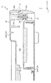
- FIG. 2 is a partial cross-sectional view of the housing of the electronic device
- FIG. 3 is an enlarged cross-sectional view of the region A shown in FIG.
- the housing 12 of the electronic device 10 includes an upper case 20 and a lower case 22, which are configured to face each other in the vertical direction (Z-axis direction).
- Electronic components such as a CPU (Central Processing Unit), a storage device, and a circuit board are housed in a space 12b formed between the upper case 20 and the lower case 22.
- CPU Central Processing Unit
- the upper case 20 and the lower case 22 are made of, for example, a magnesium alloy material or a resin material, for example, using a mold.
- the upper case 20 is roughly composed of a top surface 20a forming the upper surface 12a of the housing 12 and an outer wall 20b extending downward from the outer peripheral edge of the top surface 20a.
- the lower case 22 is roughly composed of a bottom surface 22a forming the lower surface 12c of the housing 12, and an outer wall 22b extending upward from the outer peripheral edge of the bottom surface 22a.
- the housing 12 of the electronic device 10 is configured by arranging the upper case 20 and the lower case 22 so as to face each other so that the end surface of the outer wall 20b and the end surface of the outer wall 22b face each other.
- the end face of the outer wall 20b of the upper case 20 and the end face of the outer wall 22b of the lower case 22 are not in contact with each other and are spaced apart from each other in the vertical direction (Z-axis direction). ) Is facing.
- a plurality of boss portions 20c provided in the upper case 20 and projecting downward an example of the upper boss portion
- a plurality of boss portions 20c provided in the lower case 22 and projecting upward A plurality of boss portions 22c (an example of a lower boss portion) are in contact with each other.
- the boss portions 20c and 22c that come into contact with each other are fixed to each other by screws 24. Note that FIG. 2 shows one boss portion 20c and one boss portion 22c.
- the boss portion 22c of the lower case 22 supports the boss portion 20c of the upper case 20, so that the end surface of the outer wall 20b of the upper case 20 and the end surface of the outer wall 22b of the lower case 22 face each other with a gap. Fit.
- the reason is that when the boss portions 20c and 22c are fixed to each other by screws 24 in a state where the end surface of the outer wall 20b of the upper case 20 and the end surface of the outer wall 22b of the lower case 22 are in contact with each other, the upper case 20 and the lower case 22 are fixed. This is because at least one of them can be deformed.
- the end face of the outer wall 20b of the upper case 20 and the end face of the outer wall 22b of the lower case 22 face each other with a gap. Therefore, foreign matter, particularly a liquid such as water, may enter between the end faces.
- the end face of the outer wall 20b of the upper case 20 and the end face of the outer wall 22b of the lower case 22 are provided with a multi-stage structure as a waterproof structure.
- the end surface of the outer wall 20b of the upper case 20 includes a first upper step surface 20d and a second upper step surface 20e.
- the first upper step surface 20d and the second upper step surface 20e extend substantially in the horizontal direction (X-axis direction and Y-axis direction). It should be noted that these two stepped surfaces may be parallel to each other or may not be parallel to each other.
- the second upper step surface 20e is located at a position higher than the first upper step surface 20d (that is, a position close to the top surface 20a of the upper case 20) and is inside the first upper step surface 20d. It is located at the position (that is, the inner side of the housing 12).
- first upper step surface 20d and the second upper step surface 20e on the end surface of the outer wall 20b of the upper case 20 are connected by a connection surface 20f extending substantially in the Y-axis direction and the Z-axis direction. .. Further, the first upper step surface 20d is connected to the outer surface 20g of the outer wall 20b, and the second upper step surface 20e is connected to the inner side surface 20h of the outer wall 20b.
- the end surface of the outer wall 22b of the lower case 22 includes a first lower step surface 22d, a second lower step surface 22e, and a third lower step surface 22f.
- the first lower step surface 22d, the second lower step surface 22e, and the third lower step surface 22f extend substantially in the horizontal direction (X-axis direction and Y-axis direction).
- these three step planes may be parallel to each other, and any one step plane may be non-parallel to the other step planes.
- the second lower step surface 22e is located at a position higher than the first lower step surface 22d (that is, a position close to the top surface 20a of the upper case 20) and is located on the first lower step surface 22d. On the other hand, it is located in the inner position (that is, the inner side of the housing 12).
- the third lower step surface 22f is located at a position higher than the second lower step surface 22e (that is, a position close to the top surface 20a of the upper case 20) and is located on the second lower step surface 22e. On the other hand, it is located in the inner position (that is, the inner side of the housing 12).
- first lower step surface 22d and the second lower step surface 22e on the end surface of the outer wall 22b of the lower case 22 are connected by a connection surface 22g extending substantially in the Y-axis direction and the Z-axis direction.
- second lower step surface 22e and the third lower step surface 22f are connected by a connection surface 22h extending substantially in the Y-axis direction and the Z-axis direction.
- the first lower step surface 22d is connected to the outer surface 22j of the outer wall 22b
- the third lower step surface 22f is connected to the inner side surface 22k of the outer wall 22b.
- the first upper step surface 20d on the end face of the outer wall 20b of the upper case 20 is located at a lower position and outside than the second lower step surface 22e on the end face of the outer wall 22b of the lower case 22. It is in a position (that is, on the outer side of the housing 12) and faces the first lower step surface 22d.
- the first upper step surface 20d and the first lower step surface 22d face each other with a first distance L1 substantially in the vertical direction (Z-axis direction).
- the second upper step surface 20e on the end surface of the outer wall 20b of the upper case 20 is located at a lower position and an outer position than the third lower step surface 22f on the end face of the outer wall 22b of the lower case 22. It faces the second lower step surface 22e.
- the second upper step surface 20e and the second lower step surface 22e face each other with a second distance L2 substantially in the vertical direction (Z-axis direction).
- first distance L1 and the second distance L2 when there is a manufacturing variation between the upper case 20 and the lower case 22, especially when the heights of the outer walls 20b and 22b vary within an allowable range. , Can change. However, even if such a variation occurs, between the first upper step surface 20d and the first lower step surface 22d and between the second upper step surface 20e and the second lower step surface 22e.
- the first distance L1 and the second distance L2 are set to the distances at which contact does not occur in both of the above.
- connection surface 20f on the end surface of the outer wall 20b of the upper case 20 is substantially in the width direction (X-axis direction) with respect to the connection surface 22g on the end surface of the outer wall 22b of the lower case 22.
- a third distance L3 is left between the two.
- the connecting surface 22h at the end surface of the outer wall 22b of the lower case 22 is substantially in the width direction (X-axis direction) with respect to the inner surface 20h of the outer wall 20b of the upper case 20. They face each other with a fourth distance L4.
- the housing 12 passes through the gap between these end faces and enters the housing 12. It has a simple waterproof function against possible liquids.
- the housing 12 has a waterproof function equivalent to IP (International Protection) X3. This will be described with reference to comparative examples.
- FIG. 4 is a cross-sectional view showing a gap between the end surface of the outer wall of the upper case and the end surface of the outer wall of the lower case in the housing of the comparative example.
- the end surface of the outer wall 120b of the upper case is a second position higher and inner than the first upper step surface 120d and the first upper step surface 120d. It includes an upper step surface 120e.
- the end surface of the outer wall 122b of the lower case includes the first lower step surface 122d and the second lower step surface 122e located higher and inside the first lower step surface 122d. I'm out.
- the first upper step surface 120d is located at a position lower than the height position of the second lower step surface 122e and faces the first lower step surface 122d.
- the second upper step surface 120e faces the second lower step surface 122e.
- first upper step surface 120d and the second upper step surface 120e on the end surface of the outer wall 120b of the upper case are connected by the connection surface 120f
- first upper step surface 120d is the outer surface 120g of the outer wall 120b.
- the second upper step surface 120e is connected to the inner side surface 120h of the outer wall 120b, respectively.
- the first lower step surface 122d and the second lower step surface 122e on the end surface of the outer wall 122b of the lower case are connected by a connecting surface 122g
- the first lower step surface 122d is the outer surface 122j of the outer wall 122b.
- the second lower step surface 122e is connected to the inner surface 122k of the outer wall 122b, respectively.
- the water droplets that have entered between the first upper step surface 120d and the first lower step surface 122d reach the second lower step surface 122e as they are. It flows on the second lower step surface 122e and flows into the housing.
- water droplets that have entered between the first upper step surface 20d and the first lower step surface 22d are the second lower step. Even if the surface 22e is reached, it is unlikely that the water droplets that have reached the surface 22e will get over the third lower stage surface 22f (compared to the comparative example).
- a water droplet that is, a water droplet corresponding to IPX3 that has entered between the first upper step surface 20d and the first lower step surface 22d at an angle of 60 degrees with respect to the vertical direction (Z-axis direction) is. It is not possible to get over the third lower step surface 22f.
- the housing 12 of the present embodiment has higher waterproof performance than the housing of the comparative example shown in FIG.
- the second distance L2 is larger than the third distance L3.
- the liquid that has passed between the connecting surface 20f at the end surface of the outer wall 20b of the upper case 20 and the connecting surface 22g at the end surface of the outer wall 22b of the lower case 22 is transferred to the second upper step surface 20e and the second lower surface.
- the pressure is reduced as soon as it enters between the side stage surface 22e. Due to the depressurization, the possibility that the invading liquid gets over the third lower step surface 22f of the lower case 22 can be further reduced.
- the outer contour of the outer wall 20b of the upper case 20 that is, the outer edge of the first upper step surface 20d
- the outer contour of the end surface of the outer wall 22b of 22 overlaps in the vertical direction (Z-axis direction).
- the outer surface 20g of the outer wall 20b of the upper case 20 and the outer surface 22j of the outer wall 22b of the lower case 22 form substantially one flat surface or curved surface with high design. That is, the housing 12 of the present embodiment is as described above without providing a waterproof structure on the outer surface 20g of the outer wall 20b of the upper case 20 and the outer surface 22j of the outer wall 22b of the lower case 22. It has a waterproof function.
- the thickness direction (that is, the width direction (X-axis direction) in the electronic device 10) connecting the outside and the inside of the outer wall 20b of the upper case 20 is the first.
- the size W1 of the upper step surface 20d of 1 is larger than the size W2 of the second upper step surface 20e. This is to prevent the outer wall 20b from being damaged when an external force is applied due to, for example, the housing 12 falling.
- the size of the first upper step surface 20d in the X-axis direction is smaller than the size of the second upper step surface 20e, that is, when the wall thickness of the tip of the outer wall 20b is thin, an external force is applied to the tip.
- the tip When added, a crack is generated between the connecting surface 20f and the second upper step surface 20e, and in some cases, the tip may be missing.
- the case where the thickness direction connecting the outside and the inside of the outer wall 20b of the upper case 20 is the width direction (X-axis direction) of the electronic device 10 is taken as an example, but the outer wall 20b
- the thickness direction of the electronic device 10 may be the depth direction (Y-axis direction) of the electronic device 10.
- the end faces of the outer walls of each of the two cases face each other to form a housing
- the end faces of the outer walls are not used, and the end faces of the outer walls are not used. It is possible to suppress the intrusion of the liquid into the housing through the space.
- the electronic device is a notebook personal computer, but the embodiment of the present disclosure is not limited to this.
- the embodiment of the present disclosure does not require waterproof performance against submersion, that is, it may be an electronic device having sufficient waterproof performance of IPX3.
- the electronic device includes a housing including an upper case and a lower case, and electronic components housed in the housing, and the electronic device of the upper case.
- the end face of the outer wall includes a first upper step surface and a second upper step surface at a high position and an inner position with respect to the first upper step surface
- the end face of the outer wall of the lower case is: A first lower step surface, a second lower step surface at a high position and an inner position with respect to the first lower step surface, and a high position with respect to the second lower step surface.
- the first upper step surface is lower than the second lower step surface and includes the third lower step surface at the inner position, and the first lower step surface is included.
- the second upper step surface is at a lower position with respect to the third lower step surface and faces the second lower step surface.
- the present disclosure is applicable to an electronic device in which a housing is composed of an upper case and a lower case, and electronic components are housed in the housing.
Landscapes
- Engineering & Computer Science (AREA)
- Computer Hardware Design (AREA)
- Theoretical Computer Science (AREA)
- General Engineering & Computer Science (AREA)
- Physics & Mathematics (AREA)
- Human Computer Interaction (AREA)
- General Physics & Mathematics (AREA)
- Mathematical Physics (AREA)
- Casings For Electric Apparatus (AREA)
Priority Applications (2)
| Application Number | Priority Date | Filing Date | Title |
|---|---|---|---|
| JP2021519315A JP7603211B2 (ja) | 2019-05-16 | 2020-04-16 | 電子機器 |
| US17/520,677 US11934232B2 (en) | 2019-05-16 | 2021-11-07 | Electronic apparatus |
Applications Claiming Priority (2)
| Application Number | Priority Date | Filing Date | Title |
|---|---|---|---|
| JP2019093053 | 2019-05-16 | ||
| JP2019-093053 | 2019-05-16 |
Related Child Applications (1)
| Application Number | Title | Priority Date | Filing Date |
|---|---|---|---|
| US17/520,677 Continuation US11934232B2 (en) | 2019-05-16 | 2021-11-07 | Electronic apparatus |
Publications (1)
| Publication Number | Publication Date |
|---|---|
| WO2020230508A1 true WO2020230508A1 (ja) | 2020-11-19 |
Family
ID=73289033
Family Applications (1)
| Application Number | Title | Priority Date | Filing Date |
|---|---|---|---|
| PCT/JP2020/016665 Ceased WO2020230508A1 (ja) | 2019-05-16 | 2020-04-16 | 電子機器 |
Country Status (3)
| Country | Link |
|---|---|
| US (1) | US11934232B2 (https=) |
| JP (1) | JP7603211B2 (https=) |
| WO (1) | WO2020230508A1 (https=) |
Families Citing this family (3)
| Publication number | Priority date | Publication date | Assignee | Title |
|---|---|---|---|---|
| USD981408S1 (en) * | 2018-12-20 | 2023-03-21 | Panasonic Intellectual Property Management Co., Ltd. | Portable computer |
| USD978137S1 (en) * | 2018-12-20 | 2023-02-14 | Panasonic Intellectual Property Management Co., Ltd. | Portable computer |
| USD1078726S1 (en) * | 2024-01-24 | 2025-06-10 | Getac Technology Corporation | Laptop computer |
Citations (4)
| Publication number | Priority date | Publication date | Assignee | Title |
|---|---|---|---|---|
| JPS59104583U (ja) * | 1982-12-29 | 1984-07-13 | 松下電器産業株式会社 | キヤビネツト装置 |
| JPH0967456A (ja) * | 1995-09-01 | 1997-03-11 | Inoac Corp | 防水構造及び防水性容器 |
| JP2009182553A (ja) * | 2008-01-30 | 2009-08-13 | Kyocera Corp | 電子機器 |
| WO2010119663A1 (ja) * | 2009-04-15 | 2010-10-21 | 日本電気株式会社 | 防水構造 |
Family Cites Families (14)
| Publication number | Priority date | Publication date | Assignee | Title |
|---|---|---|---|---|
| JP3023013B2 (ja) * | 1991-07-08 | 2000-03-21 | クラリオン株式会社 | ケースの組立構造 |
| JP3106964B2 (ja) | 1996-06-27 | 2000-11-06 | 住友電装株式会社 | ケースの防水構造 |
| EP1677587B1 (en) * | 2004-12-30 | 2008-10-08 | Sony Ericsson Mobile Communications AB | A sealed chassis, a seal and a method of assembling and disassembling a sealed chassis |
| JP4542944B2 (ja) * | 2005-04-28 | 2010-09-15 | 株式会社東芝 | 電子機器 |
| GB2438247B (en) | 2006-05-11 | 2011-11-02 | Nokia Corp | Improvements in or relating to liquid sensitive electronic products |
| US7760289B2 (en) * | 2007-06-27 | 2010-07-20 | Epson Imaging Devices Corporation | Electro-optic device, method of manufacturing electro-optic device and electronic equipment |
| JP5341626B2 (ja) * | 2009-06-11 | 2013-11-13 | 矢崎総業株式会社 | 防水ボックス |
| JP4714296B1 (ja) * | 2009-12-25 | 2011-06-29 | 株式会社東芝 | 電子機器 |
| CN103562825B (zh) * | 2011-05-30 | 2016-08-17 | Nlt科技股份有限公司 | 显示设备 |
| JP2013187129A (ja) * | 2012-03-09 | 2013-09-19 | Toshiba Corp | 電子機器 |
| JP6024549B2 (ja) | 2013-03-25 | 2016-11-16 | 富士通株式会社 | 電子装置 |
| JP6221065B2 (ja) * | 2013-12-26 | 2017-11-01 | パナソニックIpマネジメント株式会社 | 電子機器 |
| US9977467B2 (en) * | 2014-08-19 | 2018-05-22 | Apple Inc. | Electronic device with an enclosure stiffener |
| US20180081400A1 (en) * | 2016-09-21 | 2018-03-22 | Apple Inc. | Electronic devices with sealing elements having embedded sensors |
-
2020
- 2020-04-16 JP JP2021519315A patent/JP7603211B2/ja active Active
- 2020-04-16 WO PCT/JP2020/016665 patent/WO2020230508A1/ja not_active Ceased
-
2021
- 2021-11-07 US US17/520,677 patent/US11934232B2/en active Active
Patent Citations (4)
| Publication number | Priority date | Publication date | Assignee | Title |
|---|---|---|---|---|
| JPS59104583U (ja) * | 1982-12-29 | 1984-07-13 | 松下電器産業株式会社 | キヤビネツト装置 |
| JPH0967456A (ja) * | 1995-09-01 | 1997-03-11 | Inoac Corp | 防水構造及び防水性容器 |
| JP2009182553A (ja) * | 2008-01-30 | 2009-08-13 | Kyocera Corp | 電子機器 |
| WO2010119663A1 (ja) * | 2009-04-15 | 2010-10-21 | 日本電気株式会社 | 防水構造 |
Also Published As
| Publication number | Publication date |
|---|---|
| JPWO2020230508A1 (https=) | 2020-11-19 |
| JP7603211B2 (ja) | 2024-12-20 |
| US11934232B2 (en) | 2024-03-19 |
| US20220057842A1 (en) | 2022-02-24 |
Similar Documents
| Publication | Publication Date | Title |
|---|---|---|
| US11934232B2 (en) | Electronic apparatus | |
| CN102291954B (zh) | 复合壳体结构 | |
| JP6990879B2 (ja) | 保護部材、保護部材付きコネクタ、及び保護部材の取付構造 | |
| KR102415361B1 (ko) | 기판 유닛과 기판 어셈블리 및 그것을 이용한 카메라 모듈 | |
| CN102404959A (zh) | 电子装置及该电子装置的金属壳体的制造方法 | |
| TWI516184B (zh) | 保護結構及其電子裝置 | |
| US8139375B2 (en) | Electronic apparatus | |
| US9336968B2 (en) | Keyboard and method for assembling keyboard and portable electronic device | |
| CN103718662A (zh) | 单元安装装置、电子设备系统及单元安装装置的制造方法 | |
| US8767390B2 (en) | Electronic apparatus | |
| US8441785B2 (en) | Electronic apparatus and personal computer | |
| JP5905510B2 (ja) | 電子機器ユニットと制御盤筐体のシールド構造 | |
| US10019030B2 (en) | Electronic device | |
| US20100300739A1 (en) | Electronic apparatus and reinforcing component | |
| CN111665959A (zh) | 触控式电子设备及其触摸板装置 | |
| US20110141676A1 (en) | Cover assembly for industrial computer | |
| TWI597555B (zh) | 攝像模組保護結構 | |
| TWI700976B (zh) | 電子裝置及其殼體結構 | |
| CN106304733A (zh) | 电子元器件的保护结构及移动终端 | |
| TWI603304B (zh) | 顯示裝置 | |
| US12006967B2 (en) | Welding structure for connection of two objects | |
| JP3210561U (ja) | 撮影モジュール保護構造 | |
| JP7623533B1 (ja) | 電子機器及び筐体部材 | |
| TWI604668B (zh) | Pci-e連接器外罩與pci-e連接器模組 | |
| JP2021159985A (ja) | 板金加工品、筐体、及び、車載用電子機器 |
Legal Events
| Date | Code | Title | Description |
|---|---|---|---|
| 121 | Ep: the epo has been informed by wipo that ep was designated in this application |
Ref document number: 20805682 Country of ref document: EP Kind code of ref document: A1 |
|
| ENP | Entry into the national phase |
Ref document number: 2021519315 Country of ref document: JP Kind code of ref document: A |
|
| NENP | Non-entry into the national phase |
Ref country code: DE |
|
| 122 | Ep: pct application non-entry in european phase |
Ref document number: 20805682 Country of ref document: EP Kind code of ref document: A1 |