WO2020228064A1 - 马达的振动控制系统、方法以及电子设备 - Google Patents
马达的振动控制系统、方法以及电子设备 Download PDFInfo
- Publication number
- WO2020228064A1 WO2020228064A1 PCT/CN2019/089216 CN2019089216W WO2020228064A1 WO 2020228064 A1 WO2020228064 A1 WO 2020228064A1 CN 2019089216 W CN2019089216 W CN 2019089216W WO 2020228064 A1 WO2020228064 A1 WO 2020228064A1
- Authority
- WO
- WIPO (PCT)
- Prior art keywords
- motor
- formula
- current
- difference
- module
- Prior art date
- Legal status (The legal status is an assumption and is not a legal conclusion. Google has not performed a legal analysis and makes no representation as to the accuracy of the status listed.)
- Ceased
Links
Images


Classifications
-
- H—ELECTRICITY
- H02—GENERATION; CONVERSION OR DISTRIBUTION OF ELECTRIC POWER
- H02P—CONTROL OR REGULATION OF ELECTRIC MOTORS, ELECTRIC GENERATORS OR DYNAMO-ELECTRIC CONVERTERS; CONTROLLING TRANSFORMERS, REACTORS OR CHOKE COILS
- H02P7/00—Arrangements for regulating or controlling the speed or torque of electric DC motors
- H02P7/06—Arrangements for regulating or controlling the speed or torque of electric DC motors for regulating or controlling an individual DC dynamo-electric motor by varying field or armature current
- H02P7/18—Arrangements for regulating or controlling the speed or torque of electric DC motors for regulating or controlling an individual DC dynamo-electric motor by varying field or armature current by master control with auxiliary power
- H02P7/24—Arrangements for regulating or controlling the speed or torque of electric DC motors for regulating or controlling an individual DC dynamo-electric motor by varying field or armature current by master control with auxiliary power using discharge tubes or semiconductor devices
- H02P7/28—Arrangements for regulating or controlling the speed or torque of electric DC motors for regulating or controlling an individual DC dynamo-electric motor by varying field or armature current by master control with auxiliary power using discharge tubes or semiconductor devices using semiconductor devices
- H02P7/282—Arrangements for regulating or controlling the speed or torque of electric DC motors for regulating or controlling an individual DC dynamo-electric motor by varying field or armature current by master control with auxiliary power using discharge tubes or semiconductor devices using semiconductor devices controlling field supply only
Definitions
- the invention relates to the field of micro-motor control, and specifically includes a motor vibration control system, method and electronic equipment.
- LRA linear resonance exciter
- the excitation voltage is often preset to excite the motor to produce the expected vibration effect.
- the preset vibration effect may be distorted, which may not achieve the desired effect of the user.
- the present invention provides a vibration control system, method and electronic device for a motor in order to solve the problem of distortion of the vibration effect.
- the present invention provides a motor vibration control system, the system includes: a conversion module, an equalization module, a first conversion module, a second conversion module, an error calculation module, and an adaptive adjustment module;
- the conversion module is configured to obtain a preset excitation electrical signal output to the motor, and calculate the preset excitation electrical signal to obtain a desired displacement signal according to a transfer function from the excitation electrical signal to a displacement signal conversion;
- the equalization module is electrically connected to the conversion module, and is used to calculate the desired displacement and current parameters of the motor to obtain a drive signal;
- the first conversion module is configured to perform digital-to-analog conversion on the driving signal and output it to the motor to drive the motor;
- the second conversion module is configured to obtain the actual voltage and actual current of the motor under the current driving signal and perform analog-to-digital conversion of the actual voltage and actual current;
- the adaptive adjustment module is used to calculate the actual voltage and the current motor parameters to obtain a predicted current
- the error calculation module is used to calculate the difference between the predicted current and the actual current
- the adaptive adjustment module performs parameter iteration based on the difference to obtain motor update parameters
- the equalization module recalculates the drive signal according to the motor update parameter and the expected displacement signal.
- the transfer function is expressed by a first formula, and the first formula is:
- H(z) is the z-transformation of the transfer function of the preset excitation electrical signal change to the displacement signal
- ⁇ 0 is the resonance frequency of the motor
- f s is the sampling rate of the analog-to-digital conversion of the conversion module
- Q is the quality factor of the conversion module
- k d is the stiffness coefficient of the motor
- ⁇ is the damping coefficient of the motor
- ⁇ 0 is the electromagnetic force coefficient
- Reb is the motor resistance.
- the adaptive adjustment module uses a second formula to calculate the predicted current for the actual voltage and the current motor parameters, and the second formula is:
- i cm [n] is the actual current
- u d [n] is the mechanical velocity of the vibrator.
- the error calculation module uses a third formula to calculate the difference between the predicted current and the actual current to obtain the difference between the predicted current and the actual current, and the third formula is:
- ⁇ oei [n] is the difference function, which represents the difference of motor parameters.
- the motor update parameter includes a motor resistance update parameter for updating the motor resistance and an electromagnetic force update coefficient for updating the electromagnetic force coefficient, wherein the adaptive adjustment module uses a fourth formula to calculate the difference Get the updated motor parameters of the motor resistance, the fourth formula is:
- the adaptive adjustment module uses a fifth formula to calculate the difference to obtain the motor update parameters of the electromagnetic force coefficient.
- the fifth formula is:
- ⁇ u is the front coefficient of the adaptive filter.
- the equalization module uses a sixth formula to calculate the expected displacement and motor update parameters to obtain a drive signal, and the sixth formula is:
- ⁇ d and Q d is the equilibrium modules desired resonant frequency and quality factor
- ⁇ c is the gain factor
- ⁇ c is the gain coefficient obtained from the following expression:
- the present invention provides a vibration control method of a motor, the method includes:
- the desired displacement and the current parameters of the motor are calculated to obtain a drive signal
- the driving signal performs digital-to-analog conversion to drive the motor
- the drive signal is recalculated according to the motor update parameter and the expected displacement signal.
- the adaptive adjustment module performs parameter iteration to obtain motor update parameters according to the difference.
- the specific method includes:
- the compensation amount is obtained according to the difference.
- the transfer function is identified by a first formula, and the first formula is:
- H(z) is the z-transformation of the transfer function of the preset excitation electrical signal change to the displacement signal
- ⁇ 0 is the resonance frequency of the motor
- f s is the sampling rate of the analog-to-digital conversion of the conversion module
- Q is the quality factor of the conversion module
- k d is the stiffness coefficient of the motor
- ⁇ is the damping coefficient of the motor
- ⁇ 0 is the electromagnetic force coefficient
- Reb is the motor resistance.
- the calculating the predicted current according to the drive signal and the motor resistance specifically includes using a second formula to calculate the predicted current for the actual voltage and the current motor parameters, and the second formula is
- i cm [n] is the actual current
- u d [n] is the mechanical velocity of the vibrator.
- the calculating the difference between the predicted current and the actual current specifically includes using a third formula to calculate the difference between the predicted current and the actual current, and the third formula is:
- ⁇ oei [n] is the difference function, which represents the difference of motor parameters.
- the motor update parameter includes a motor resistance update parameter for updating the motor resistance and an electromagnetic force update coefficient for updating the electromagnetic force coefficient, wherein the adaptive adjustment module uses a fourth formula to calculate the difference Get the updated motor parameters of the motor resistance, the fourth formula is:
- the adaptive adjustment module uses a fifth formula to calculate the difference to obtain the motor update parameters of the electromagnetic force coefficient.
- the fifth formula is:
- ⁇ u is the front coefficient of the adaptive filter.
- the recalculating the drive signal according to the motor update parameter and the expected displacement signal specifically includes: calculating the motor update parameter and the expected displacement signal according to a sixth formula to obtain a new drive Signal, the sixth formula is: calculated according to the following expression,
- ⁇ d and Q d is the equilibrium modules desired resonant frequency and quality factor
- ⁇ c is the gain factor
- ⁇ c is the gain coefficient obtained from the following expression:
- the present invention also provides an electronic device including a motor and a vibration control system of the above-mentioned motor.
- the present invention provides a motor vibration control system, which obtains motor update parameters according to the motor closed-loop control technology of actual voltage and actual current detection, and obtains new driving signals through the calculation of the equalization module to achieve The purpose of reducing the distortion of the vibration effect and improving the user experience.
- Fig. 1 is a schematic diagram of the structure of the vibration control system of the motor of the present invention.
- Fig. 2 is a schematic flow chart of a vibration control method of a motor.
- Figure 3 is a schematic diagram of the structure of the electronic device of the present invention.
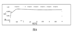
- Fig. 4 is a graph showing the change of a1 in the embodiment of the present invention.
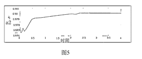
- Fig. 5 is a graph showing the change of a2 in the embodiment of the present invention.
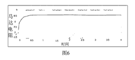
- Fig. 6 is a graph showing the variation of motor resistance Reb in an embodiment of the present invention.
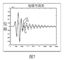
- Figure 7 is a vibration waveform diagram of the motor of the present invention.
- Embodiments of the present invention provide a motor vibration control system, method, and electronic equipment.
- the drive signal that drives the motor vibration is adjusted by the conversion module and the equalization module to drive the motor to vibrate.
- the adaptive adjustment module calculates the compensation amount according to the actual voltage and current of the motor, and sends it to the equalization module to continue adjusting and driving.
- the signal forms a closed-loop system, which makes the vibration of the motor more stable, avoids the distortion of the vibration effect, and improves the user experience.
- the vibration control system of the motor is mainly applied to electronic devices equipped with motors, which include but are not limited to smart phones, tablet computers and wearable devices.
- a vibration control system for a motor of the present invention includes: a conversion module 10, an equalization module 20, a first conversion module 30, a second conversion module 40, an error calculation module 50, and an adaptive adjustment module 60.
- the conversion module 10 is connected to a signal source of the excitation electrical signal, and is used to obtain a preset excitation electrical signal v n output to the motor 70, and perform a conversion on the preset excitation electrical signal according to the transfer function from the excitation electrical signal v n to the displacement signal. Calculate the desired displacement signal.
- the preset excitation electrical signal v n is set according to the vibration effect desired by the user.
- the transfer function is expressed by a first formula, and the first formula is
- ⁇ 0 is the resonance frequency of the motor
- f s is the sampling rate of analog-to-digital conversion in the conversion module 10
- Q is the quality factor of the motor
- k d is the stiffness coefficient of the motor.
- the equalization module 20 is electrically connected to the conversion module 10, and is used to calculate the desired displacement and the current parameters of the motor to obtain a driving signal; the motor parameters include motor resistance, electromagnetic force coefficient, and the like.
- the equalization module 20 uses a sixth formula to calculate the expected displacement and motor update parameters to obtain a drive signal, and the sixth formula is:
- ⁇ d and Q d are the expected resonant frequency and quality factor of the equalization module 20, and ⁇ d and Q d can be configured directly.
- ⁇ c is the gain coefficient, where ⁇ c is the gain coefficient obtained according to the following expression
- Reb and ⁇ 0 are the current resistance and electromagnetic force coefficient of the motor 70, respectively.
- Is the stiffness coefficient, k d is obtained mainly through the following formula:
- md is the mass of the motor vibrator
- ⁇ 0 is obtained by the following formula
- a 1 and a 2 are the parameters of the second-order model.
- the first conversion module 30 is configured to perform digital-to-analog conversion on the driving signal and output it to the motor 70 to drive the motor.
- the driving signal of the driving motor 70 is transmitted from the equalization module 20 to the first conversion module 30, and the first conversion module 30 is a digital-to-analog converter.
- the driving signal output by the equalization module 20 can be output to the motor 70 to drive the motor after digital-to-analog conversion.
- a signal amplifier 80 is further included for amplifying the driving signal to better drive the motor 70.
- the second conversion module 40 is configured to obtain the actual voltage v cm and the actual current i cm of the motor under the current driving signal, and perform analog-to-digital conversion of the actual voltage v cm and the actual current i cm .
- the second conversion module 40 includes an analog-to-digital converter 40a and an analog-to-digital converter 40b.
- the analog-to-digital converter 40a is used to collect the actual current i cm
- the analog-to-digital converter 40b is used to collect the driving signal of the motor 70.
- the actual voltage v cm a voltage divider
- the analog-to-digital converter 40a at one end of the actual current i cm is connected to the two ends of the high-sensitive resistor 402, and the high-sensitive resistor 402 is connected in series with one end of the motor 70 to function as a voltage divider to avoid the excessively high external voltage of the electronic equipment causing the two ends of the motor 70.
- the problem of insufficient terminal voltage is also conducive to the detection of the actual current i cm .
- the error calculation module 50 is used to calculate the difference between the predicted current i cp and the actual current i cm .
- the error calculation module 50 using the third prediction formula and the actual current CP currents i i i cm & lt calculating CP derive predicted current and the actual current i cm & lt difference between, the third formula is:
- ⁇ oei [n] is a difference function, which represents the difference between the predicted current i cp and the actual current i cm .
- the adaptive adjustment module 60 is configured to calculate the predicted current i cp according to the actual voltage and current motor parameters, and transmit the predicted current i cp to the error calculation module 50 to calculate the difference function.
- the predicted current i cp is obtained by calculation by the adaptive adjustment module 60.
- the adaptive adjustment module 60 uses the second formula to calculate the predicted current for the actual voltage and the current motor parameters.
- the second formula is the specific calculation formula as follows:
- Reb is the motor resistance
- ⁇ 0 is the electromagnetic force coefficient
- u d [n] is the mechanical velocity of the vibrator
- the product of the electromagnetic force and the velocity is the back electromotive force EMF caused by the mechanical motion on the electric circuit part.
- displacement x d [n] and velocity u d [n] are modeled by classical second-order model, and the expression is as follows:
- x d [n] ⁇ x f cp [n-1]-a 3 x d [n-1]-a 4 x d [n-2]
- u d [n] ⁇ u f cp [n]- ⁇ u f cp [n-2]-a 1 u d [n-1]-a 2 u d [n-2]
- ⁇ u , ⁇ x and a 1 , a 2 are the parameters of the second-order model
- the adaptive adjustment module 60 also performs parameter iteration to obtain the motor update parameters according to the difference, and transmits the iterated motor update parameters to the equalization module 20 to update the motor parameters in the equalization module 20 to adjust the output driving signal.
- the adaptive adjustment module 60 is a recursive filter, and the adaptive adjustment module 60 uses the difference between the predicted current and the actual current in combination with LMS (Least Mean Square) to obtain motor update parameters.
- the motor update parameters include the updated motor resistance and the updated electromagnetic force coefficient, wherein the adaptive adjustment module uses a fourth formula to calculate the difference to obtain the motor resistance update parameter of the motor resistance, and the fourth formula is :
- the adaptive adjustment module uses a fifth formula to calculate the difference between the electromagnetic force coefficient and the motor electromagnetic force coefficient update parameter.
- the fifth formula is:
- ⁇ u is the front coefficient of the adaptive filter
- the adaptive adjustment module 60 When the adaptive adjustment module 60 performs parameter iteration based on the difference to obtain the motor update parameter Reb [n+1] of the motor resistance and the motor update parameter ⁇ 0 [n+1] of the electromagnetic force coefficient, then R eb [n+1] And ⁇ 0 [n+1] as the current resistance and electromagnetic force coefficient to adjust the output drive signal.
- the equalization module 20 adjusts the expected displacement according to the motor update parameters, so that the vibration effect of the motor 70 It is more in line with the needs of users and reduces the influence of external factors on the vibration effect.
- FIG. 2 is a schematic flowchart of a method for controlling vibration of a motor.
- the motor vibration control method is applied to the above motor vibration control system, and the specific method includes:
- Step 101 Obtain a preset excitation electrical signal output to the motor, and perform calculations on the preset excitation electrical signal according to a transfer function from the excitation electrical signal to a displacement signal to obtain a desired displacement signal.
- the transfer function is identified by a first formula, and the first formula is:
- H(z) is the z-transformation of the transfer function that presets the change of the excitation electrical signal to the displacement signal.
- the transfer function is used to characterize the linear time-invariant system that controls the vibration of the motor.
- the transfer function It is the z transformation of the unit impulse response of the excitation electrical signal input by the system, so z is used as a variable for characterization. among them
- ⁇ 0 is the resonance frequency of the motor
- f s is the sampling rate of the analog-to-digital conversion in the conversion module
- Q is the quality factor of the motor
- k d is the stiffness coefficient of the motor.
- Step S102 The expected displacement and the current parameters of the motor are calculated to obtain a drive signal.
- a new drive signal is obtained by calculating the motor update parameter and the expected displacement signal according to the sixth formula, and the sixth formula is: calculated according to the following expression,
- ⁇ d and Q d are the expected resonant frequency and quality factor of the equalization module, where ⁇ d and Q d can be directly configured, ⁇ c is the gain coefficient, where ⁇ c is the gain coefficient obtained according to the following expression
- R ed and ⁇ 0 are the current resistance and electromagnetic force coefficient of the motor respectively.
- k d is the stiffness coefficient. In the process of calculating the compensation amount in the adaptive adjustment module, it will affect k d and obtain a new value of k d .
- Step S103 The driving signal performs digital-to-analog conversion to drive the motor.
- Step S104 Obtain the actual voltage and actual current of the motor under the current driving signal, and perform analog-to-digital conversion on the actual voltage and actual current.
- Step S105 Calculate the predicted current according to the actual voltage and the current motor parameters.
- i cp is the predicted current
- the second formula is used to calculate the predicted current for the actual voltage and the current motor parameters.
- the second formula is:
- Reb is the motor resistance
- ⁇ 0 is the electromagnetic force coefficient
- u d [n] is the mechanical velocity of the vibrator
- the product of the electromagnetic force and the velocity is the back electromotive force EMF caused by the mechanical motion on the electric circuit part.
- displacement x d [n] and velocity u d [n] are modeled by classical second-order model, and the expression is as follows:
- x d [n] ⁇ x f cp [n-1]-a 1 x d [n-1]- ⁇ 2 x d [n-2]
- u d [n] ⁇ u f cp [n]- ⁇ u f cp [n-2]-a 1 u d [n-1]-a 2 u d [n-2]
- ⁇ u , ⁇ x and a 1 , a 2 are the parameters of the second-order model
- f cp [n] is the electromagnetic force, which can be expressed as
- Step S106 Calculate the difference between the predicted current and the actual current.
- a third formula is used to calculate the difference between the predicted current and the actual current, and the third formula is:
- ⁇ oei [n] is a difference function, which represents the difference between the predicted current and the actual current.
- Step S107 Perform parameter iteration based on the difference to obtain motor update parameters.
- the adaptive adjustment module 60 is a recursive filter, and the adaptive adjustment module 60 uses the difference between the predicted current and the actual current in combination with LMS (Least Mean Square, Least Mean Square) Find motor update parameters.
- the motor update parameter includes a motor resistance update parameter for updating the motor resistance and an electromagnetic force update coefficient for updating the electromagnetic force coefficient, wherein the adaptive adjustment module uses a fourth formula to calculate the difference to obtain the motor resistance of the motor Update the parameters, the fourth formula is:
- the adaptive adjustment module uses a fifth formula to calculate the difference to obtain the motor update parameters of the electromagnetic force coefficient.
- the fifth formula is:
- ⁇ u is the front coefficient of the adaptive filter.
- Step S108 recalculate the drive signal according to the updated parameters of the motor and the expected displacement signal. Perform parameter iteration based on the difference to obtain the motor update parameter Reb [n+1] of the motor resistance and the motor update parameter ⁇ 0 [n+1] of the electromagnetic force coefficient, and then combine Reb [n+1] and ⁇ 0 [n+1] ] As the current resistance and electromagnetic force coefficient, adjust the output drive signal.
- FIG. 3 is a schematic structural diagram of an electronic device of the present invention.
- the electronic device 100 includes a motor 70 and the motor vibration control system 200 of the above-mentioned embodiment.
- FIG. 4 is a graph of the change of a1 in the embodiment of the present invention.
- FIG. 5 is a graph showing the change of a2 in the embodiment of the present invention.
- FIG. 6 is a graph showing the variation of motor resistance Reb in an embodiment of the present invention.
- Figure 7 shows the vibration waveform of the motor.
- S1 is a vibration waveform diagram of the expected motor vibration
- S2 is a vibration waveform diagram of a system motor using the embodiment of the present invention
- S3 is a vibration waveform diagram of a motor vibration not using the system of the present invention. It can be seen that the vibration waveform diagram of the system provided by the embodiment of the present invention almost overlaps with the expected vibration waveform diagram of motor vibration, which is very different from the vibration waveform of the system without using the present invention. Therefore, the use of the system of the present invention can make the motor vibration closer to the expected vibration.
- the above embodiments provide a motor vibration control system, a motor vibration control method, and electronic equipment.
- the motor update parameters are obtained through the motor closed-loop control technology that detects the actual voltage and actual current, and the new parameters are obtained through the calculation of the equalization module.
- the vibration control system of the motor is more robust and the user experience is improved.
Landscapes
- Engineering & Computer Science (AREA)
- Power Engineering (AREA)
- Control Of Electric Motors In General (AREA)
Abstract
本发明提供了一种马达的振动控制系统,系统包括:变换模块、均衡模块、第一转化模块、第二转化模块、误差计算模块以及自适应调节模块。预设激励电信号变换为期望的位移进行运算得到驱动信号驱动马达振动;自适应调节模块根据驱动信号和马达电阻计算出预测电流;根据差异运算出马达参数更新量;所述均衡模块根据所述马达更新参数和所述期望的位移信号重新运算出所述驱动信号,以调整输出给马达的驱动信号。本发明还提供一种马达的振动控制方法和电子设备。自适应调节模块根据实际电压和实际电流检测的马达闭环控制技术来获取马达更新参数,并通过均衡模块的来抵消参数的变化,以达到减少振动效果畸变的目的。
Description
本发明涉微电机控制领域,具体包括马达的振动控制系统、方法以及电子设备。
目前,智能手机、平板电脑等便携设备应用的越来越普及。在便携设备中设置触觉反馈已成为提升用户体验的一种有效方法。通常,这些便携设备中通过放置线性谐振激励器(LRA,简称马达)来实现振动功能,而往往预先设置好激励电压来激励马达产生预期的振动效果。然而,由于马达单体差异、设备所处环境、设备握持方式等的差异,可能会使预设的振动效果产生畸变,从而达不到用户预期的效果。
【发明内容】
本发明针对解决振动效果产生畸变的问题,而提供一种马达的振动控制系统、方法以及电子设备。
为实现上述目的,本发明提供了一种马达的振动控制系统,所述系统包括:变换模块、均衡模块、第一转化模块、第二转化模块、误差计算模块以及自适应调节模块;
所述变换模块用于获取输出至所述马达的预设激励电信号,并根据激励电信号至位移信号变换的传递函数对所述预设激励电信号进行运算得到期望的位移信号;
所述均衡模块电连接至所述变换模块,用于对所述期望的位移和马达当前参数进行运算得到驱动信号;
所述第一转化模块用于对所述驱动信号进行数模转换后输出给所述马达以驱动所述马达;
所述第二转换模块用于获取所述马达在当前驱动信号下的实际电压和实际电流并将所述实际电压和实际电流进行模数转换;
所述自适应调节模块用于对所述实际电压以及所述当前马达参数进行运算 得出预测电流;
所述误差计算模块用于计算所述预测电流和所述实际电流之间的差异;
所述自适应调节模块根据所述差异进行参数迭代得到马达更新参数;
所述均衡模块根据所述马达更新参数和所述期望的位移信号重新运算出所述驱动信号。
进一步地,所述传递函数用第一公式表示,所述第一公式为:

H(z)为预设激励电信号变化为位移信号的传递函数的z变换,其中,


Ω
0为所述马达的谐振频率,f
s为所述变换模块模数转换的采样率,Q为变换模块的品质因子,k
d为所述马达的劲度系数,ζ为马达的阻尼系数,φ
0为电磁力系数,R
eb为马达电阻。
进一步地,所述自适应调节模块利用第二公式对所述实际电压以及所述当前马达参数计算出预测电流,所述第二公式为:

i
cp为预测电流,i
cm[n]为实际电流,u
d[n]为振子机械速度。
进一步地,所述误差计算模块利用第三公式对所述预测电流和所述实际电流运算得出所述预测电流和所述实际电流之间的差异,所述第三公式为,
ε
oei[n]=i
cm[n]-i
cp[n]
其中,ε
oei[n]为差异函数,表示马达参数的差异。
进一步地,所述马达更新参数包括对马达电阻进行更新的马达电阻更新参数和对电磁力系数进行更新的电磁力更新系数,其中,所述自适应调节模块利用第四公式对所述差异进行运算得到马达电阻的马达更新参数,第四公式为:

所述自适应调节模块利用第五公式对所述差异进行运算得到电磁力系数的马达更新参数,第五公式为:

其中,


进一步地,所述均衡模块利用第六公式对所述期望的位移和马达更新参数进行运算得到驱动信号,所述第六公式为:

其中,
b
1-a=a
1,b
2-a=a
2,


其中,Ω
d和Q
d为均衡模块的期望谐振频率和品质因子,σ
c为增益系数,其中,σ
c为增益系数根据以下表达式获得:

本发明提供了一种马达的振动控制方法,所述方法包括:
获取输出至马达的预设激励电信号,并根据激励电信号至位移信号变换的传递函数对所述预设激励电信号进行运算得到期望的位移信号;
所述期望的位移和马达当前参数进行运算得到驱动信号;
所述驱动信号进行数模转换驱动所述马达;
获取所述马达在当前驱动信号下的实际电压和实际电流并将所述实际电压 和实际电流进行模数转换;
根据所述实际电压以及所述当前马达参数进行运算得出预测电流;
计算所述预测电流和所述实际电流之间的差异;
根据所述差异进行参数迭代得到马达更新参数;
根据所述马达更新参数和所述期望的位移信号重新运算出所述驱动信号。
进一步地,所述自适应调节模块根据所述差异进行参数迭代得到马达更新参数,具体方法包括,
根据LMS最小均方算法,根据所述差异获取所述补偿量。
进一步地,所述传递函数用第一公式标识,所述第一公式为:

H(z)为预设激励电信号变化为位移信号的传递函数的z变换,其中,


Ω
0为所述马达的谐振频率,f
s为所述变换模块模数转换的采样率,Q为变换模块的品质因子,k
d为所述马达的劲度系数,ζ为马达的阻尼系数,φ
0为电磁力系数,R
eb为马达电阻。
进一步地,所述根据驱动信号和马达电阻计算出预测电流,具体包括利用第二公式对实际电压以及所述当前马达参数计算出预测电流,所述第二公式为

i
cp为预测电流,i
cm[n]为实际电流,u
d[n]为振子机械速度。
进一步地,所述计算所述预测电流和所述实际电流之间的差异,具体包括利用第三公式对预测电流和所述实际电流运算得到差异,所述第三公式为:
ε
oei[n]=i
cm[n]-i
cp[n]
其中,ε
oei[n]为差异函数,表示马达参数的差异。
进一步地,所述马达更新参数包括对马达电阻进行更新的马达电阻更新参数和对电磁力系数进行更新的电磁力更新系数,其中,所述自适应调节模块利用第四公式对所述差异进行运算得到马达电阻的马达更新参数,第四公式为:

所述自适应调节模块利用第五公式对所述差异进行运算得到电磁力系数的马达更新参数,第五公式为:

其中,


进一步地,所述根据所述马达更新参数和所述期望的位移信号重新运算出所述驱动信号,具体包括,根据第六公式对马达更新参数和所述期望的位移信号进行运算得到新的驱动信号,所述第六公式为:,根据以下表达式计算得到,

其中,
b
1-a=a
1,b
2-a=a
2,


其中,Ω
d和Q
d为均衡模块的期望谐振频率和品质因子,σ
c为增益系数,其中,σ
c为增益系数根据以下表达式获得:

本发明还提供一种电子设备,包括马达和上述马达的振动控制系统。
本发明的有益效果是:本发明提供一种马达的振动控制系统,根据实际电压和实际电流检测的马达闭环控制技术来获取马达更新参数,并通过均衡模块的运算获得新的驱动信号,以达到减少振动效果畸变的目的,提高用户的使用体验。
图1是本发明马达的振动控制系统的结构示意图。
图2为马达的振动控制方法的流程示意图。
图3为本发明电子设备的结构示意图。
图4为本发明实施例中a1的变化曲线图。
图5为本发明实施例中a2的变化曲线图。
图6为本发明实施例中马达电阻Reb的变化曲线图。
图7为本发明马达的振动波形图。
为了使本发明实施方式的目的、技术方案和优点更加清楚,下面将结合附图对本发明的各个实施方式进行详细的阐述。然而,本领域的普通技术人员可以理解,在本发明各实施方式中,为了使读者更好理解本发明而提出了许多技术细节。但是,即使没有这些技术细节和基于以下各实施方式的种种变化和修改,也可以实现本发明所要求保护的技术方案。
本发明实施例的提供了马达的振动控制系统、方法以及电子设备。马达的振动控制系统中,驱动马达振动的驱动信号经过变换模块和均衡模块调整后驱动马达振动,同时由自适应调节模块根据马达的实际电压和电流,计算补偿量,发送至均衡模块继续调整驱动信号,形成了闭环系统,使马达的振动更稳定,避免了振动效果产生畸变,提高了用户的体验。该马达的振动控制系统主要应用于装配有马达的电子设备,电子设备包括但不限于智能手机、平板电脑和可穿戴设备。
请参看图1,图1为马达的振动控制系统的结构示意图。本发明的一种马达的振动控制系统,所述系统包括:变换模块10、均衡模块20、第一转化模块30、第二转化模块40、误差计算模块50以及自适应调节模块60。
变换模块10连接激励电信号的信号源,用于获取输出至马达70的预设激励 电信号v
n,并根据激励电信号v
n至位移信号变换的传递函数对所述预设激励电信号进行运算得到期望的位移信号。所述预设激励电信号v
n是根据用户期望的振动效果进行设置。
具体的,所述传递函数用第一公式表示,所述第一公式为

其中


Ω
0为所述马达的谐振频率,f
s为所述变换模块10中模数转换的采样率,Q为所述马达的品质因子,k
d为所述马达的劲度系数。
均衡模块20电连接至变换模块10,用于对期望的位移和马达当前参数进行运算得到驱动信号;马达参数包括马达电阻、电磁力系数等。
具体的,所述均衡模块20利用第六公式对所述期望的位移和马达更新参数进行运算得到驱动信号,所述第六公式为,

其中,
b
1-a=a
1,b
2-a=a
2,


其中,Ω
d和Q
d为均衡模块20的期望谐振频率和品质因子,其中Ω
d和Q
d直 接配置即可。σ
c为增益系数,其中,σ
c为增益系数根据以下表达式获得

其中,R
eb、φ
0分别是马达70的当前的电阻和电磁力系数。为劲度系数,k
d的获得主要通过以下公式获得:
k
d=ω
0*ω
0*md
其中,md为马达振子质量,ω
0由以下公式获得

a
1、a
2为二阶模型的参数,。
第一转化模块30用于对驱动信号进行数模转换后输出给马达70以驱动所述马达。
具体的,驱动马达70的驱动信号由均衡模块20传输至第一转换模块30,第一转换模块30为数模转换器。均衡模块20输出的驱动信号进行数模转换后,才能输出给马达70以驱动所述马达。在本实施例中,还包括信号放大器80,用于放大驱动信号,以更好驱动马达70。
第二转换模块40用于获取所述马达在当前驱动信号下的实际电压v
cm和实际电流i
cm并将实际电压v
cm和实际电流i
cm进行模数转换。
具体的,第二转化模块40包括模数转换器40a和模数转换其40b,模数转换器40a用于采集实际电流i
cm,模数转换其40b用于采集马达70在驱动信号驱动下的实际电压v
cm。其中,测量实际电流i
cm一端的模数转换器40a连接在高敏电阻402两端,该高敏电阻402串联于马达70一端,起分压作用,以避免电子设备的外加电压过高造成马达70两端电压不足问题,也有利于实际电流i
cm的检测。
误差计算模块50用于计算预测电流i
cp和实际电流i
cm之间的差异。
具体的,误差计算模块50利用第三公式对预测电流i
cp和实际电流i
cm运算得出预测电流i
cp和实际电流i
cm之间的差异,所述第三公式为:
ε
oei[n]=i
cm[n]-i
cp[n]
其中,ε
oei[n]为差异函数,表示所述预测电流i
cp和所述实际电流i
cm之间的 差异。
整理可得第三公式变换式为:

自适应调节模块60用于根据实际电压以及当前马达参数进行运算得出预测电流i
cp,并将预测电流i
cp传输给误差计算模块50,计算差异函数。
具体的,预测电流i
cp通过自适应调节模块60的计算获得,自适应调节模块60利用第二公式对实际电压以当前马达参数计算出预测电流,第二公式为具体计算公式如下:

具体的,Reb为马达电阻,φ
0为电磁力系数,u
d[n]为振子机械速度,电磁力和速度的乘积为机械运动对电回路部分带来的反向电动势EMF。位移x
d[n]和速度u
d[n]均进行经典的二阶模型建模,表达式如下:
x
d[n]=σ
xf
cp[n-1]-a
3x
d[n-1]-a
4x
d[n-2]
u
d[n]=σ
uf
cp[n]-σ
uf
cp[n-2]-a
1u
d[n-1]-a
2u
d[n-2]
其中,σ
u、σ
x和a
1、a
2为二阶模型的参数,f
cp[n]为电磁力,可以表示为f
cp[n]=φ
0i
cm[n]。
自适应调节模块60还根据差异进行参数迭代得到马达更新参数,并将迭代的马达更新参数传输给均衡模块20,以对均衡模块20里的马达参数进行更新,从而调整输出的驱动信号。
具体的,自适应调节模块60为递归滤波器,自适应调节模块60利用所述预测电流和所述实际电流之间的差异结合LMS(Least mean square,最小均方算法)求取马达更新参数。马达更新参数包括对更新后的马达电阻及更新后的电磁力系数,其中,所述自适应调节模块利用第四公式对所述差异进行运算得到马达电阻的马达阻值更新参数,第四公式为:

所述自适应调节模块利用第五公式对所述差异进行运算得到电磁力系数的马达电磁力系数更新参数,第五公式为:

其中,


当自适应调节模块60根据差异进行参数迭代得到马达电阻的马达更新参数R
eb[n+1]和电磁力系数的马达更新参数φ
0[n+1],则将R
eb[n+1]和φ
0[n+1]作为当前的电阻和电磁力系数,调整输出的驱动信号。
通过采集马达70的实际电压v
cm和实际电流i
cm,反馈至自适应调节模块60获取得到马达更新参数,均衡模块20根据马达更新参数对期望的位移做出调整,能够使马达70的振动效果更符合用户的需求,减少外界因素对振动效果的影响。
请参看图2,图2为马达的振动控制方法的流程示意图。该马达的振动控制方法应用于上述的马达的振动控制系统,具体方法包括:
步骤101:获取输出至马达的预设激励电信号,并根据激励电信号至位移信号变换的传递函数对所述预设激励电信号进行运算得到期望的位移信号。
具体的,所述传递函数用第一公式标识,所述第一公式为:

H(z)为预设激励电信号变化为位移信号的传递函数的z变换,在本实施中,使用传递函数来表征控制马达的振动的线性时不变系统,在离散域中,该传递函数就是系统输入的激励电信号单位脉冲响应的z变换,所以采用z为变量进行表征。其中


Ω
0为所述马达的谐振频率,f
s为所述变换模块中模数转换的采样率,Q为所述马达的品质因子,k
d为所述马达的劲度系数。
步骤S102:所述期望的位移和马达当前参数进行运算得到驱动信号。
具体的,根据第六公式对马达更新参数和所述期望的位移信号进行运算得到新的驱动信号,所述第六公式为:,根据以下表达式计算得到,

其中,
b
1-a=a
1,b
2-a=a
2,


其中,Ω
d和Q
d为均衡模块的期望谐振频率和品质因子,其中Ω
d和Q
d直接配置即可,σ
c为增益系数,其中,σ
c为增益系数根据以下表达式获得

其中,R
ed、φ
0分别是马达的当前电阻和电磁力系数。k
d为劲度系数,在自适应调整模块计算补偿量过程,会对k
d影响,获得新的k
d值。
步骤S103:所述驱动信号进行数模转换驱动所述马达。
步骤S104:获取所述马达在当前驱动信号下的实际电压和实际电流并将所述实际电压和实际电流进行模数转换。
步骤S105:根据所述实际电压以及所述当前马达参数进行运算得出预测电流。
具体的,i
cp为预测电流,利用第二公式对实际电压以及所述当前马达参数计算出预测电流,所述第二公式为:

具体的,Reb为马达电阻,φ
0为电磁力系数,u
d[n]为振子机械速度,电磁 力和速度的乘积为机械运动对电回路部分带来的反向电动势EMF。位移x
d[n]和速度u
d[n]均进行经典的二阶模型建模,表达式如下:
x
d[n]=σ
xf
cp[n-1]-a
1x
d[n-1]-σ
2x
d[n-2]
u
d[n]=σ
uf
cp[n]-σ
uf
cp[n-2]-a
1u
d[n-1]-a
2u
d[n-2]
其中,σ
u、σ
x和a
1、a
2为二阶模型的参数,f
cp[n]为电磁力,可以表示为
f
cp[n]=φ
0i
cm[n]
步骤S106:计算所述预测电流和所述实际电流之间的差异。
具体的,利用第三公式对预测电流和所述实际电流运算得到差异,所述第三公式为,
ε
oei[n]=i
cm[n]-i
cp[n]
其中,ε
oei[n]为差异函数,表示所述预测电流和所述实际电流之间的差异。
整理可得第三公式的变形式:

步骤S107:根据所述差异进行参数迭代得到马达更新参数。
具体的,在本实施例中,自适应调节模块60为递归滤波器,自适应调节模块60利用所述预测电流和所述实际电流之间的差异结合LMS(Least mean square,最小均方算法)求取马达更新参数。马达更新参数包括对马达电阻进行更新的马达电阻更新参数和对电磁力系数进行更新的电磁力更新系数,其中,所述自适应调节模块利用第四公式对所述差异进行运算得到马达电阻的马达更新参数,第四公式为:

所述自适应调节模块利用第五公式对所述差异进行运算得到电磁力系数的马达更新参数,第五公式为:

其中,


通过上述公式,计算获得迭代的马达更新参数R
ed[n+1]、φ
0[n+1]。
步骤S108:根据所述马达更新参数和所述期望的位移信号重新运算出所述驱动信号。根据差异进行参数迭代得到马达电阻的马达更新参数R
eb[n+1]和电磁力系数的马达更新参数φ
0[n+1],将R
eb[n+1]和φ
0[n+1]作为当前的电阻和电磁力系数,调整输出的驱动信号。
请参看图3,图3为本发明电子设备的结构示意图,该电子设备100包括马达70和上述实施例的马达的振动控制系统200。
请参看图4,图4为本发明实施例中a1的变化曲线图。
请参看图5,图5为本发明实施例中a2的变化曲线图。
请参看图6,图6为本发明实施例中马达电阻Reb的变化曲线图。
如上述附图4-6所示,可以看出,使用本发明的马达的振动控制系统,能够快速调节马达参数,使马达快速恢复至期望的振动效果。
请参看图7,图7为马达的振动波形图。其中S1为期待的马达振动的振动波形图,S2为使用本发明实施例系统马达的振动波形图,S3为不使用本发明系统马达振动的振动波形图。可以看出,本发明实施例提供的系统的振动波形图与期待的马达振动的振动波形图几乎重叠,与不使用本发明系统的振动波形相差甚大。因此,使用本发明系统的能够使马达振动更接近期待振动。
上述实施例,提供了一种马达的振动控制系统和马达的振动控制方法以及电子设备,通过检测实际电压和实际电流的马达闭环控制技术来获取马达更新参数,并通过均衡模块的来运算获得新的驱动信号,以达到减少振动效果畸变的目的,使马达的振动控制系统更稳健,提高用户的使用体验。
以上所述的仅是本发明的实施方式,在此应当指出,对于本领域的普通技术人员来说,在不脱离本发明创造构思的前提下,还可以做出改进,但这些均属于本发明的保护范围。
Claims (14)
- 一种马达的振动控制系统,其特征在于,所述系统包括:变换模块、均衡模块、第一转化模块、第二转化模块、误差计算模块以及自适应调节模块;所述变换模块用于获取输出至所述马达的预设激励电信号,并根据激励电信号至位移信号变换的传递函数对所述预设激励电信号进行运算得到期望的位移信号;所述均衡模块电连接至所述变换模块,用于对所述期望的位移和马达当前参数进行运算得到驱动信号;所述第一转化模块用于对所述驱动信号进行数模转换后输出给所述马达以驱动所述马达;所述第二转换模块用于获取所述马达在当前驱动信号下的实际电压和实际电流并将所述实际电压和实际电流进行模数转换;所述自适应调节模块用于对所述实际电压以及所述当前马达参数进行运算得出预测电流;所述误差计算模块用于计算所述预测电流和所述实际电流之间的差异;所述自适应调节模块根据所述差异进行参数迭代得到马达更新参数;所述均衡模块根据所述马达更新参数和所述期望的位移信号重新运算出所述驱动信号。
- 根据权利要求1所述马达的振动控制系统,其特征在于,所述传递函数用第一公式表示,所述第一公式为:
 H(z)为预设激励电信号变化为位移信号的传递函数的z变换,其中,

 Ω 0为所述马达的谐振频率,f s为所述变换模块模数转换的采样率,Q为变换模块的品质因子,k d为所述马达的劲度系数,ζ为马达的阻尼系数,φ 0为电磁力系数,R eb为马达电阻。
 - 根据权利要求2所述的马达的振动控制系统,其特征在于,所述自适应调节模块利用第二公式对所述实际电压以及所述当前马达参数计算出预测电流,所述第二公式为:
 i cp为预测电流,i cm[n]为实际电流,u d[n]为振子机械速度。
 - 根据权利要求3所述的马达的振动控制系统,其特征在于,所述误差计算模块利用第三公式对所述预测电流和所述实际电流运算得出所述预测电流和所述实际电流之间的差异,所述第三公式为,ε oei[n]=i cm[n]-i cp[n]其中,ε oei[n]为差异函数,表示马达参数的差异。
- 根据权利要求4所述的马达的振动控制系统,其特征在于,所述马达更新参数包括对马达电阻进行更新的马达电阻更新参数和对电磁力系数进行更新的电磁力更新系数,其中,所述自适应调节模块利用第四公式对所述差异进行运算得到马达电阻的马达更新参数,第四公式为:
 所述自适应调节模块利用第五公式对所述差异进行运算得到电磁力系数的马达更新参数,第五公式为:
 其中,
其中, 均为迭代的步长,σ u为自适应滤波器前项系数。
- 根据权利要求5所述的马达的振动控制系统,其特征在于,所述均衡模块利用第六公式对所述期望的位移和马达更新参数进行运算得到驱动信号,所 述第六公式为:
 其中,b 1-a=a 1,b 2-a=a 2,

 其中,Ω d和Q d为均衡模块的期望谐振频率和品质因子,σ c为增益系数,其中,σ c为增益系数根据以下表达式获得:
- 一种马达的振动控制方法,其特征在于,所述方法包括:获取输出至马达的预设激励电信号,并根据激励电信号至位移信号变换的传递函数对所述预设激励电信号进行运算得到期望的位移信号;所述期望的位移和马达当前参数进行运算得到驱动信号;所述驱动信号进行数模转换驱动所述马达;获取所述马达在当前驱动信号下的实际电压和实际电流并将所述实际电压和实际电流进行模数转换;根据所述实际电压以及所述当前马达参数进行运算得出预测电流;计算所述预测电流和所述实际电流之间的差异;根据所述差异进行参数迭代得到马达更新参数;根据所述马达更新参数和所述期望的位移信号重新运算出所述驱动信号。
- 根据权利要求7所述的马达的振动控制方法,其特征在于,自适应调节模块根据所述差异进行参数迭代得到马达更新参数,具体方法包括,根据LMS最小均方算法,根据所述差异获取补偿量。
- 根据权利要求7所述马达的振动控制方法,其特征在于,所述传递函数用第一公式标识,所述第一公式为:
 H(z)为预设激励电信号变化为位移信号的传递函数的z变换,其中,


 Ω 0为所述马达的谐振频率,f s为所述变换模块模数转换的采样率,Q为变换模块的品质因子,k d为所述马达的劲度系数,ζ为马达的阻尼系数,φ 0为电磁力系数,R eb为马达电阻。
 - 根据权利要求9所述的马达的振动控制方法,其特征在于,所述根据驱动信号和马达电阻计算出预测电流,具体包括利用第二公式对实际电压以及所述当前马达参数计算出预测电流,所述第二公式为
 i cp为预测电流,i cm[n]为实际电流,u d[n]为振子机械速度。
 - 根据权利要求10所述的马达的振动控制方法,其特征在于,所述计算所述预测电流和所述实际电流之间的差异,具体包括利用第三公式对预测电流和所述实际电流运算得到差异,所述第三公式为:ε oei[n]=i cm[n]-i cp[n]其中,ε oei[n]为差异函数,表示马达参数的差异。
- 根据权利要求11所述的马达的振动控制方法,其特征在于,所述马达更新参数包括对马达阻值进行更新的马达电阻更新参数和对电磁力系数进行更新的电磁力更新系数,其中,自适应调节模块利用第四公式对所述差异进行运算得到马达电阻的马达阻值更新参数,第四公式为:
 所述自适应调节模块利用第五公式对所述差异进行运算得到电磁力系数的马达电磁力系数更新参数,第五公式为:
 其中,
其中, 均为迭代的步长,σ u为自适应滤波器前项系数。
- 根据权利要求12所述的马达的振动控制方法,其特征在于,所述根据所述马达更新参数和所述期望的位移信号重新运算出所述驱动信号,具体包括,根据第六公式对马达更新参数和所述期望的位移信号进行运算得到新的驱动信号,所述第六公式为:根据以下表达式计算得到,
 其中,b 1-a=a 1,b 2-a=a 2,

 其中,Ω d和Q d为均衡模块的期望谐振频率和品质因子,σ c为增益系数,其中,σ c为增益系数根据以下表达式获得:
- 一种电子设备,其特征在于,包括马达和上述权利要求1-6任意一种马达的振动控制系统。
Applications Claiming Priority (2)
| Application Number | Priority Date | Filing Date | Title |
|---|---|---|---|
| CN201910397617.4 | 2019-05-14 | ||
| CN201910397617.4A CN110266223B (zh) | 2019-05-14 | 2019-05-14 | 马达的振动控制系统、方法以及电子设备 |
Publications (1)
| Publication Number | Publication Date |
|---|---|
| WO2020228064A1 true WO2020228064A1 (zh) | 2020-11-19 |
Family
ID=67914643
Family Applications (1)
| Application Number | Title | Priority Date | Filing Date |
|---|---|---|---|
| PCT/CN2019/089216 Ceased WO2020228064A1 (zh) | 2019-05-14 | 2019-05-30 | 马达的振动控制系统、方法以及电子设备 |
Country Status (2)
| Country | Link |
|---|---|
| CN (1) | CN110266223B (zh) |
| WO (1) | WO2020228064A1 (zh) |
Cited By (3)
| Publication number | Priority date | Publication date | Assignee | Title |
|---|---|---|---|---|
| CN113282115A (zh) * | 2021-05-31 | 2021-08-20 | 华中科技大学 | 相移广义积分扩张状态观测器、振动抑制方法及系统 |
| CN113655713A (zh) * | 2021-06-17 | 2021-11-16 | 中国人民解放军海军工程大学 | 一种振动主动控制系统抗冲击优化方法 |
| CN113949325A (zh) * | 2021-10-29 | 2022-01-18 | 歌尔股份有限公司 | 线性马达的控制方法、控制装置、设备以及介质 |
Families Citing this family (10)
| Publication number | Priority date | Publication date | Assignee | Title |
|---|---|---|---|---|
| WO2021120057A1 (zh) * | 2019-12-18 | 2021-06-24 | 瑞声声学科技(深圳)有限公司 | 一种信号制作方法、信号制作装置、振动马达及触屏设备 |
| CN111552371B (zh) * | 2019-12-25 | 2023-11-03 | 瑞声科技(新加坡)有限公司 | 激励电压生成方法、装置、设备及介质、测试方法及系统 |
| WO2021128077A1 (zh) * | 2019-12-25 | 2021-07-01 | 瑞声声学科技(深圳)有限公司 | 激励电压生成方法、装置、设备及介质、测试方法及系统 |
| CN111220263A (zh) * | 2020-01-15 | 2020-06-02 | 上海艾为电子技术股份有限公司 | 一种检测马达谐振频率的方法和系统 |
| CN111782444B (zh) * | 2020-06-09 | 2024-12-31 | 北京小米移动软件有限公司 | 一种马达测试系统及方法、计算机存储介质 |
| CN111694436B (zh) * | 2020-06-18 | 2022-09-02 | 瑞声科技(新加坡)有限公司 | 一种触觉效果的实现方法及设备、计算机可读存储介质 |
| CN111957543B (zh) * | 2020-07-24 | 2021-04-16 | 中国飞机强度研究所 | 一种激振器输出力控制方法及控制模型 |
| CN113325311B (zh) * | 2021-05-31 | 2022-06-21 | 歌尔股份有限公司 | 振动电机特性参数获取方法、设备及存储介质 |
| CN113283152B (zh) * | 2021-06-01 | 2023-05-02 | 上海艾为电子技术股份有限公司 | 驱动电信号的调整方法、驱动方法及驱动电路、电子设备 |
| CN113992104B (zh) * | 2021-10-22 | 2025-07-25 | 上海艾为电子技术股份有限公司 | 马达的传递函数确定、驱动方法和系统、电子设备 |
Citations (4)
| Publication number | Priority date | Publication date | Assignee | Title |
|---|---|---|---|---|
| CN101895241A (zh) * | 2009-05-22 | 2010-11-24 | 台达电子工业股份有限公司 | 双电源马达控制系统及其马达控制装置 |
| JP2012222950A (ja) * | 2011-04-08 | 2012-11-12 | Panasonic Corp | 圧縮機モータ制御装置 |
| CN103345037A (zh) * | 2013-07-04 | 2013-10-09 | 聚辰半导体(上海)有限公司 | 相机音圈马达执行器的整形信号控制方法 |
| CN109274308A (zh) * | 2018-08-13 | 2019-01-25 | 瑞声科技(新加坡)有限公司 | 马达参数控制系统及马达参数控制方法 |
Family Cites Families (4)
| Publication number | Priority date | Publication date | Assignee | Title |
|---|---|---|---|---|
| CN100562823C (zh) * | 2007-09-13 | 2009-11-25 | 暨南大学 | 一种复杂轨迹的轮廓控制方法 |
| JP2012070604A (ja) * | 2010-09-27 | 2012-04-05 | On Semiconductor Trading Ltd | モータ駆動回路 |
| CN108415556B (zh) * | 2018-01-29 | 2021-04-20 | 瑞声科技(新加坡)有限公司 | 马达振动控制方法及装置 |
| CN109194238B (zh) * | 2018-08-09 | 2022-06-14 | 瑞声科技(新加坡)有限公司 | 一种基于电流反馈信号的马达控制系统及方法 |
-
2019
- 2019-05-14 CN CN201910397617.4A patent/CN110266223B/zh active Active
- 2019-05-30 WO PCT/CN2019/089216 patent/WO2020228064A1/zh not_active Ceased
Patent Citations (4)
| Publication number | Priority date | Publication date | Assignee | Title |
|---|---|---|---|---|
| CN101895241A (zh) * | 2009-05-22 | 2010-11-24 | 台达电子工业股份有限公司 | 双电源马达控制系统及其马达控制装置 |
| JP2012222950A (ja) * | 2011-04-08 | 2012-11-12 | Panasonic Corp | 圧縮機モータ制御装置 |
| CN103345037A (zh) * | 2013-07-04 | 2013-10-09 | 聚辰半导体(上海)有限公司 | 相机音圈马达执行器的整形信号控制方法 |
| CN109274308A (zh) * | 2018-08-13 | 2019-01-25 | 瑞声科技(新加坡)有限公司 | 马达参数控制系统及马达参数控制方法 |
Cited By (5)
| Publication number | Priority date | Publication date | Assignee | Title |
|---|---|---|---|---|
| CN113282115A (zh) * | 2021-05-31 | 2021-08-20 | 华中科技大学 | 相移广义积分扩张状态观测器、振动抑制方法及系统 |
| CN113655713A (zh) * | 2021-06-17 | 2021-11-16 | 中国人民解放军海军工程大学 | 一种振动主动控制系统抗冲击优化方法 |
| CN113655713B (zh) * | 2021-06-17 | 2023-08-29 | 中国人民解放军海军工程大学 | 一种振动主动控制系统抗冲击优化方法 |
| CN113949325A (zh) * | 2021-10-29 | 2022-01-18 | 歌尔股份有限公司 | 线性马达的控制方法、控制装置、设备以及介质 |
| CN113949325B (zh) * | 2021-10-29 | 2024-04-09 | 歌尔股份有限公司 | 线性马达的控制方法、控制装置、设备以及介质 |
Also Published As
| Publication number | Publication date |
|---|---|
| CN110266223A (zh) | 2019-09-20 |
| CN110266223B (zh) | 2021-12-21 |
Similar Documents
| Publication | Publication Date | Title |
|---|---|---|
| WO2020228064A1 (zh) | 马达的振动控制系统、方法以及电子设备 | |
| CN113678091B (zh) | 用于改进换能器动力学特性的方法和系统 | |
| US11509292B2 (en) | Identifying mechanical impedance of an electromagnetic load using least-mean-squares filter | |
| KR102600718B1 (ko) | 열 보호 및 저항 추정을 위한 트랜듀서의 열 모델 | |
| CN103780997B (zh) | 音频电源管理系统及其方法 | |
| CN110350828B (zh) | 马达参数追踪方法及系统 | |
| CN105916079B (zh) | 一种扬声器非线性补偿方法及装置 | |
| CN109274308B (zh) | 马达参数控制系统及马达参数控制方法 | |
| JP6299363B2 (ja) | 駆動装置 | |
| KR102811085B1 (ko) | 자속에 기반한 음향 변환기에 대한 비선형 거동의 보상 시스템 및 방법 | |
| WO2007013622A1 (ja) | スピーカ装置 | |
| WO2023071641A1 (zh) | 线性马达的控制方法、控制装置、设备以及介质 | |
| JP2007081815A (ja) | スピーカ装置 | |
| US11228284B2 (en) | Controlling parameters of an amplifier system based on a measured physical quantity | |
| CN116154801A (zh) | 一种电声换能器自适应宽带匹配控制方法及装置 | |
| CN111885475A (zh) | 用于补偿声换能器的非线性行为的系统和方法 | |
| CN111130375B (zh) | 精确调节虚拟阻抗的方法与单机逆变器、逆变器并联系统 | |
| CN112420012A (zh) | 家电设备的主动降噪装置、控制方法及家电设备 | |
| CN209488798U (zh) | 一种音频装置及电子设备 | |
| TW201626814A (zh) | 揚聲器之頻率響應補償系統 | |
| CN108768237B (zh) | 一种基于状态空间的永磁电机比例谐振控制器设计方法 | |
| TWI828909B (zh) | 藉由預測可用的電源供應能量來避免聲頻電源傳輸削波 | |
| CN103872988B (zh) | 一种频率失调下的前馈式窄带主动控制系统 | |
| US20230170854A1 (en) | Modulator feedforward compensation | |
| CN103636231B (zh) | 用于扬声器保护的前置滤波 |
Legal Events
| Date | Code | Title | Description |
|---|---|---|---|
| 121 | Ep: the epo has been informed by wipo that ep was designated in this application |
Ref document number: 19928388 Country of ref document: EP Kind code of ref document: A1 |
|
| NENP | Non-entry into the national phase |
Ref country code: DE |
|
| 122 | Ep: pct application non-entry in european phase |
Ref document number: 19928388 Country of ref document: EP Kind code of ref document: A1 |