US11228284B2 - Controlling parameters of an amplifier system based on a measured physical quantity - Google Patents
Controlling parameters of an amplifier system based on a measured physical quantity Download PDFInfo
- Publication number
- US11228284B2 US11228284B2 US16/272,215 US201916272215A US11228284B2 US 11228284 B2 US11228284 B2 US 11228284B2 US 201916272215 A US201916272215 A US 201916272215A US 11228284 B2 US11228284 B2 US 11228284B2
- Authority
- US
- United States
- Prior art keywords
- amplifier
- amplifier system
- estimated
- parameters
- response
- Prior art date
- Legal status (The legal status is an assumption and is not a legal conclusion. Google has not performed a legal analysis and makes no representation as to the accuracy of the status listed.)
- Active, expires
Links
Images


Classifications
-
- H—ELECTRICITY
- H03—ELECTRONIC CIRCUITRY
- H03F—AMPLIFIERS
- H03F1/00—Details of amplifiers with only discharge tubes, only semiconductor devices or only unspecified devices as amplifying elements
- H03F1/30—Modifications of amplifiers to reduce influence of variations of temperature or supply voltage or other physical parameters
-
- G—PHYSICS
- G01—MEASURING; TESTING
- G01R—MEASURING ELECTRIC VARIABLES; MEASURING MAGNETIC VARIABLES
- G01R27/00—Arrangements for measuring resistance, reactance, impedance, or electric characteristics derived therefrom
- G01R27/02—Measuring real or complex resistance, reactance, impedance, or other two-pole characteristics derived therefrom, e.g. time constant
- G01R27/08—Measuring resistance by measuring both voltage and current
-
- G—PHYSICS
- G01—MEASURING; TESTING
- G01R—MEASURING ELECTRIC VARIABLES; MEASURING MAGNETIC VARIABLES
- G01R27/00—Arrangements for measuring resistance, reactance, impedance, or electric characteristics derived therefrom
- G01R27/02—Measuring real or complex resistance, reactance, impedance, or other two-pole characteristics derived therefrom, e.g. time constant
- G01R27/26—Measuring inductance or capacitance; Measuring quality factor, e.g. by using the resonance method; Measuring loss factor; Measuring dielectric constants ; Measuring impedance or related variables
- G01R27/2605—Measuring capacitance
-
- G—PHYSICS
- G01—MEASURING; TESTING
- G01R—MEASURING ELECTRIC VARIABLES; MEASURING MAGNETIC VARIABLES
- G01R27/00—Arrangements for measuring resistance, reactance, impedance, or electric characteristics derived therefrom
- G01R27/02—Measuring real or complex resistance, reactance, impedance, or other two-pole characteristics derived therefrom, e.g. time constant
- G01R27/26—Measuring inductance or capacitance; Measuring quality factor, e.g. by using the resonance method; Measuring loss factor; Measuring dielectric constants ; Measuring impedance or related variables
- G01R27/2611—Measuring inductance
-
- H—ELECTRICITY
- H03—ELECTRONIC CIRCUITRY
- H03F—AMPLIFIERS
- H03F13/00—Amplifiers using amplifying element consisting of two mechanically- or acoustically-coupled transducers, e.g. telephone-microphone amplifier
-
- H—ELECTRICITY
- H03—ELECTRONIC CIRCUITRY
- H03F—AMPLIFIERS
- H03F3/00—Amplifiers with only discharge tubes or only semiconductor devices as amplifying elements
- H03F3/181—Low frequency amplifiers, e.g. audio preamplifiers
- H03F3/183—Low frequency amplifiers, e.g. audio preamplifiers with semiconductor devices only
- H03F3/187—Low frequency amplifiers, e.g. audio preamplifiers with semiconductor devices only in integrated circuits
-
- H—ELECTRICITY
- H03—ELECTRONIC CIRCUITRY
- H03F—AMPLIFIERS
- H03F3/00—Amplifiers with only discharge tubes or only semiconductor devices as amplifying elements
- H03F3/45—Differential amplifiers
- H03F3/45071—Differential amplifiers with semiconductor devices only
- H03F3/45076—Differential amplifiers with semiconductor devices only characterised by the way of implementation of the active amplifying circuit in the differential amplifier
- H03F3/45475—Differential amplifiers with semiconductor devices only characterised by the way of implementation of the active amplifying circuit in the differential amplifier using IC blocks as the active amplifying circuit
-
- H—ELECTRICITY
- H03—ELECTRONIC CIRCUITRY
- H03F—AMPLIFIERS
- H03F2200/00—Indexing scheme relating to amplifiers
- H03F2200/03—Indexing scheme relating to amplifiers the amplifier being designed for audio applications
Definitions
- the present disclosure relates in general to a mobile device, and more particularly, to controlling parameters of an amplifier system based on a measured physical quantity.
- Audio systems often include an amplifier driving a vibrational transducer.
- a vibrational transducer may include, without limitation, a loudspeaker that includes a magnetic voice-coil transducer, a magnetic voice-coil transducer that mechanically vibrates a surface (e.g., a screen of a smartphone, tablet, personal computer, or other device), and a piezoelectric actuator that mechanically vibrates a surface.
- the vibrational transducer may, in response to an input signal received by the vibrational transducer, generate vibrational energy to vibrate the loudspeaker or surface to generate sound.
- properties of the vibrational transducer may change as a function of temperature and/or other environmental factors, or there may be changes from one device to another due to variations in manufacturing tolerances which in turn affect a frequency response of the audio system.
- Other properties that may change include an elasticity/compliance of a vibrational transducer and a coupling factor that may determine how efficiently electrical energy is converted into mechanical stress or strain in the vibrational transducer.
- FIG. 7 illustrates a graph depicting a variation in frequency response of a piezoelectric transducer for three values of a dielectric constant corresponding to three different operating temperatures, as is known in the art.
- Systems and methods are desired which maintain a stable audio performance and frequency response of a system comprising a vibrational transducer despite changes in temperature and other environmental conditions and variation due to manufacturing tolerances.
- the disadvantages and problems associated with minimizing variation in an audio system response to changes in temperature and environment and variations in manufacturing process may be reduced or eliminated.
- a method for controlling one or more parameters of an amplifier system may include receiving an indication of a physical quantity associated with the amplifier system, determining one or more parameters of the amplifier system in response to the indication, and causing the amplifier system to operate in accordance with the one or more parameters.
- an apparatus for controlling one or more parameters of an amplifier system may include at least one input configured to receive an indication of a physical quantity associated with the amplifier system and a controller configured to determine one or more parameters of the amplifier system in response to the indication and cause the amplifier system to operate in accordance with the one or more parameters.
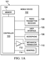
- FIG. 1A illustrates a block diagram of selected components of an example mobile device, in accordance with embodiments of the present disclosure
- FIG. 1B illustrates an exploded perspective view of selected components of an example mobile device, in accordance with embodiments of the present disclosure
- FIG. 2A illustrates a circuit diagram of an example amplifier and piezoelectric transducer for generating acoustical sound via a screen surface, in accordance with embodiments of the present disclosure
- FIG. 2B illustrates a circuit diagram of an example amplifier and coil-based dynamic transducer for generating acoustical sound via a screen surface, in accordance with embodiments of the present disclosure
- FIG. 3 illustrates selected portions of a mobile device including detail of selected components of a controller wherein a frequency response of an amplifier system is varied as a function of an estimated temperature associated with the amplifier system, in accordance with embodiments of the present disclosure
- FIG. 5A illustrates a block diagram of selected components of an impedance estimator for estimating capacitance of a load driven by an amplifier, in accordance with embodiments of the present disclosure
- FIG. 5B illustrates a block diagram of selected components of another impedance estimator for estimating capacitance of a load driven by an amplifier, in accordance with embodiments of the present disclosure
- FIG. 6 illustrates selected portions of a mobile device including detail of selected components of a controller wherein a selected amplifier configuration of an amplifier system may be selected based on an estimated impedance of a load driven by the amplifier system, in accordance with embodiments of the present disclosure
- FIG. 7 illustrates a graph depicting a variation in frequency response of a piezoelectric transducer for three values of a dielectric constant corresponding to three different operating temperatures, as is known in the art.
- FIG. 1A illustrates a block diagram of selected components of an example mobile device 102 , in accordance with embodiments of the present disclosure.
- mobile device 102 may comprise an enclosure 101 , a controller 103 , a memory 104 , a user interface 105 , a microphone 106 , a radio transmitter/receiver 108 , a mechanical transducer 110 , an amplifier 112 , and one or more sensors 114 .
- Enclosure 101 may comprise any suitable housing, casing, or other enclosure for housing the various components of mobile device 102 .
- Enclosure 101 may be constructed from plastic, metal, and/or any other suitable materials.
- enclosure 101 may be adapted (e.g., sized and shaped) such that mobile device 102 is readily transported on a person of a user of mobile device 102 .
- mobile device 102 may include but is not limited to a smart phone, a tablet computing device, a handheld computing device, a personal digital assistant, a notebook computer, or any other device that may be readily transported on a person of a user of mobile device 102 .
- Controller 103 is housed within enclosure 101 and may include any system, device, or apparatus configured to interpret and/or execute program instructions and/or process data, and may include, without limitation, a microprocessor, microcontroller, digital signal processor (DSP), application specific integrated circuit (ASIC), or any other digital or analog circuitry configured to interpret and/or execute program instructions and/or process data.
- controller 103 may interpret and/or execute program instructions and/or process data stored in memory 104 and/or other computer-readable media accessible to controller 103 .
- Memory 104 may be housed within enclosure 101 , may be communicatively coupled to controller 103 , and may include any system, device, or apparatus configured to retain program instructions and/or data for a period of time (e.g., computer-readable media).
- Memory 104 may include random access memory (RAM), electrically erasable programmable read-only memory (EEPROM), a Personal Computer Memory Card International Association (PCMCIA) card, flash memory, magnetic storage, opto-magnetic storage, or any suitable selection and/or array of volatile or non-volatile memory that retains data after power to mobile device 102 is turned off.
- RAM random access memory
- EEPROM electrically erasable programmable read-only memory
- PCMCIA Personal Computer Memory Card International Association
- User interface 105 may be housed at least partially within enclosure 101 , may be communicatively coupled to controller 103 , and may comprise any instrumentality or aggregation of instrumentalities by which a user may interact with mobile device 102 .
- user interface 105 may permit a user to input data and/or instructions into mobile device 102 (e.g., via a keypad and/or touch screen), and/or otherwise manipulate mobile device 102 and its associated components.
- User interface 105 may also permit mobile device 102 to communicate data to a user, e.g., by way of a display device.
- Microphone 106 may be housed at least partially within enclosure 101 , may be communicatively coupled to controller 103 , and may comprise any system, device, or apparatus configured to convert sound incident at microphone 106 to an electrical signal that may be processed by controller 103 , wherein such sound is converted to an electrical signal using a diaphragm or membrane having an electrical capacitance that varies as based on sonic vibrations received at the diaphragm or membrane.
- Microphone 106 may include an electrostatic microphone, a condenser microphone, an electret microphone, a microelectromechanical systems (MEMS) microphone, or any other suitable capacitive microphone.
- MEMS microelectromechanical systems
- Radio transmitter/receiver 108 may be housed within enclosure 101 , may be communicatively coupled to controller 103 , and may include any system, device, or apparatus configured to, with the aid of an antenna, generate and transmit radio-frequency signals as well as receive radio-frequency signals and convert the information carried by such received signals into a form usable by controller 103 .
- Radio transmitter/receiver 108 may be configured to transmit and/or receive various types of radio-frequency signals, including without limitation, cellular communications (e.g., 2G, 3G, 4G, LTE, etc.), short-range wireless communications (e.g., BLUETOOTH), commercial radio signals, television signals, satellite radio signals (e.g., GPS), Wireless Fidelity, etc.
- cellular communications e.g., 2G, 3G, 4G, LTE, etc.
- short-range wireless communications e.g., BLUETOOTH
- commercial radio signals e.g., television signals, satellite radio signals (e.g., GPS),
- Mechanical transducer 110 may be housed at least partially within enclosure 101 or may be external to enclosure 101 , may be communicatively coupled to controller 103 (e.g., via a respective amplifier 112 ), and may comprise any system, device, or apparatus made with one or more materials configured to generate electric potential or voltage when mechanical strain is applied to mechanical transducer 110 , or conversely to undergo mechanical displacement or change in size or shape (e.g., change dimensions along a particular plane) when a voltage is applied to mechanical transducer 110 .
- a mechanical transducer may comprise a piezoelectric transducer made with one or more materials configured to, in accordance with the piezoelectric effect, generate electric potential or voltage when mechanical strain is applied to mechanical transducer 110 , or conversely to undergo mechanical displacement or change in size or shape (e.g., change dimensions along a particular plane) when a voltage is applied to mechanical transducer 110 .
- mechanical transducer 110 may comprise a voice coil structure similar to a dynamic loudspeaker, which employs a lightweight diaphragm mechanically coupled to a rigid frame via a flexible suspension that constrains a voice coil to move axially through a cylindrical magnetic gap.
- a dynamic loudspeaker which employs a lightweight diaphragm mechanically coupled to a rigid frame via a flexible suspension that constrains a voice coil to move axially through a cylindrical magnetic gap.
- a magnetic field is created by the electric current in the voice coil, making it a variable electromagnet.
- the coil and the driver's magnetic system interact, generating a mechanical force that causes the coil (and thus, the attached cone) to move back and forth, thereby reproducing sound under the control of the applied electrical signal coming from an amplifier.
- mechanical transducer 110 may comprise a voice coil structure similar to a dynamic loudspeaker, but without a diaphragm, such that that voice coil drives mechanical vibration of a surface of mobile device 102 .
- a sensor 114 may comprise any suitable system, device, or apparatus configured to sense a physical quantity within mobile device 102 and generate a signal indicative of such physical quantity.
- a sensor 114 may comprise a temperature sensor 114 (e.g., a thermometer, thermistor, etc.) configured to sense a temperature within mobile device 102 (e.g., proximate to amplifier 112 ) and communicate a signal to controller 103 indicative of such temperature.
- a sensor 114 may comprise a voltage sensor configured to sense a voltage associated with mechanical transducer 110 (e.g., a voltage across terminals of mechanical transducer 110 ).
- a sensor may comprise a current sensor configured to sense a current associated with mechanical transducer 110 (e.g., a current delivered from amplifier 112 and/or flowing through a terminal of mechanical transducer 110 ).
- a mobile device 102 in accordance with this disclosure may comprise one or more components not specifically enumerated above.
- FIG. 1B illustrates an exploded perspective view of selected components of example mobile device 102 , in accordance with embodiments of the present disclosure.
- enclosure 101 may include a main body 120 , a mechanical transducer assembly 116 , and a cover assembly 130 , such that when constructed, mechanical transducer assembly 116 is interfaced between main body 120 and cover assembly 130 .
- Main body 120 may house a number of electronics, including controller 103 , memory 104 , radio transmitter/receiver 108 , and/or microphone 106 , as well as a display (e.g., a liquid crystal display) of user interface 105 .
- a display e.g., a liquid crystal display
- Mechanical transducer assembly 116 may comprise a frame 124 configured to hold and provide mechanical structure for one or more mechanical transducers 110 (which may be coupled to controller 103 ) and transparent film 128 .
- Cover assembly 130 may comprise a frame 132 configured to hold and provide mechanical structure for transparent cover 134 .
- Transparent cover 134 may be made from any suitable material (e.g., ceramic) that allows visibility through transparent cover 134 , protection of mechanical transducer 110 and display 122 , and/or user interaction with display 122 .
- FIG. 1B illustrates mechanical transducer assembly 116 being situated between cover assembly 130 and display 122
- mechanical transducer assembly 116 may reside “behind” display 122 , such that display 122 is situated between cover 130 and mechanical transducer assembly 116 .
- FIG. 1B illustrates mechanical transducer 110 located at the edge of mechanical transducer assembly 116 (and thus, at or near the edge of display 122 ), mechanical transducer 110 may be located at any suitable location below transparent cover 134 and/or display 122 .
- Mechanical transducers including piezoelectric transducers and coil-based dynamic transducers, are typically used to convert electric signals into mechanical force.
- one or more mechanical transducers 110 may cause vibration on a surface of transparent cover 134 , which in turn may produce pressure waves in air, generating human-audible sound.
- one or more mechanical transducers 110 may be driven by respective amplifiers 112 under the control of controller 103 in order to generate acoustical sound by vibrating the surface of transparent cover 134 .
- a mechanical transducer 110 in a mobile device 102
- the systems and methods disclosed in this application may be applied generally to any other suitable vibrational transducer, including without limitation a traditional microspeaker independent of a mobile device, a standalone loudspeaker, and a loudspeaker integral to a device other than a mobile device (e.g., a television or radio).
- FIG. 2A illustrates a circuit diagram of an example amplifier 112 A and a mechanical transducer implemented as a piezoelectric transducer 110 A for generating acoustical sound via a screen surface, in accordance with embodiments of the present disclosure.
- amplifier 112 A which may be configured as a voltage-controlled voltage source, may receive an input signal and generate an appropriate output signal based on the input signal in order to drive piezoelectric transducer 110 A directly, or in some cases such as when a Class D or switching amplifier is used, via a matching/filter network.
- piezoelectric transducer 110 A may be mechanically coupled to a screen (e.g., display 122 and/or transparent cover 134 ), and may cause mechanical movement/vibration of such screen in order to generate acoustical sound.
- a screen e.g., display 122 and/or transparent cover 134
- FIG. 2B illustrates a circuit diagram of an example amplifier 112 B and a mechanical transducer implemented as a coil-based dynamic transducer 110 B for generating acoustical sound via a screen surface, in accordance with embodiments of the present disclosure.
- amplifier 112 B which may be configured as a voltage-controlled voltage source, may receive an input signal and generate an appropriate output signal based on the input signal in order to drive coil-based dynamic transducer 110 B directly, or in some cases such as when a Class D or switching amplifier is used, via a matching/filter network.
- coil-based dynamic transducer 110 B may be mechanically coupled to a screen (e.g., display 122 and/or transparent cover 134 ), and may cause mechanical movement/vibration of such screen in order to generate acoustical sound.
- a screen e.g., display 122 and/or transparent cover 134
- amplifier 112 is depicted driving a mechanical transducer 110 , in some embodiments of the present disclosure, amplifier 112 may drive a suitable load other than a mechanical transducer.
- processor 103 may receive an indication of a physical quantity associated with the amplifier system comprising amplifier 112 and one or more other components of mobile device 102 . In response to the indication, processor 103 may determine one or more parameters for operation of the amplifier system and cause the amplifier system to operate in accordance with the one or more parameters.
- such physical quantity may comprise an estimated temperature associated with the amplifier system and the one or more parameters may comprise a frequency response of the amplifier system, as set forth in greater detail below with respect to FIGS. 3-5B below.
- such physical quantity may comprise an estimated impedance associated with the amplifier system and the one or more parameters may comprise a selected amplifier configuration associated with the amplifier system, as set forth in greater detail below with respect to FIG. 6 .
- FIG. 3 illustrates selected portions of mobile device 102 including detail of selected components of controller 103 wherein a frequency response of an amplifier system comprising amplifier 112 is varied as a function of an estimated temperature associated with the amplifier system, in accordance with embodiments of the present disclosure.
- mobile device 102 may include a signal path for driving a load 110 (which may or may not comprise a mechanical transducer) wherein the signal path comprises amplifier 112 and a filter 302 (e.g., implemented by controller 103 ) having a variable frequency response, wherein the filter 302 may filter an input signal INPUT and output a filtered version of input signal INPUT to amplifier 112 .
- Controller 103 may also implement a frequency response selector 304 .
- Frequency response selector 304 may be configured to receive an electrical signal indicative of an estimated temperature sensed by sensor 114 and based on the estimated temperature, determine a selected frequency response of filter 302 , such that the selected frequency response of filter 302 varies as a function of the estimated temperature. Accordingly, filter 302 effectively serves as an equalization filter that may equalize frequency response variations of the amplifier system caused by variances in temperature.
- a desired reference stable frequency response for the audio system of mobile device 102 may be defined.
- filter 302 in connection with frequency response selector 304 may apply an inverse filter which when applied to input signal INPUT results in the desired reference response when the system is at the temperature associated with such inverse filter.
- the response of this filter may be a negative difference in decibels across frequency between the measured frequency response at the selected temperature (e.g., shown in FIG. 7 ) and the desired reference frequency response.
- frequency response selector 304 may be configured to calculate the selected frequency response as a function of estimated temperature.
- a component of mobile device 102 e.g., memory 104
- frequency response selector 304 may select the selected frequency response from the plurality of stored frequency responses based on the estimated temperature (e.g., via a look-up table, which may also be stored in memory 104 or another component of mobile device 102 ).
- not every estimated temperature may map directly to a stored frequency response, in which case frequency response selector 304 may select two frequency responses corresponding to the estimated temperature from the plurality of stored frequency responses and interpolate between the two selected frequency responses to set the selected frequency response.
- controller 103 may determine an estimated temperature by monitoring one or more physical quantities of load 110 .
- FIG. 4 illustrates selected portions of mobile device 102 including detail of selected components of controller 103 wherein a frequency response of an amplifier system comprising amplifier 112 is varied as a function of an estimated temperature associated with the amplifier system, with the estimated temperature based on an estimated impedance of load 110 driven by the amplifier system, in accordance with embodiments of the present disclosure.
- the embodiments represented by FIG. 4 may be similar in many respects to the embodiments represented by FIG. 3 , and thus, only the main differences between FIG. 3 and FIG. 4 may be described below. In particular, the embodiments represented by FIG.
- an impedance estimator 402 configured to receive a current monitoring signal I MON indicative of a current associated with load 110 (as sensed by a sensor 114 implemented as a current sensor) and a voltage monitoring signal V MON indicative of a voltage associated with load 110 (as sensed by a sensor 114 implemented as a voltage sensor) and based on such signals may determine an estimated impedance Z of load 110 . If the impedance of load 110 varies monotonically with temperature, estimated impedance Z may serve as a proxy of an estimated temperature such that frequency response selector 304 may select a selected frequency response based on the estimated impedance, wherein the estimated impedance is indicative of an estimated temperature.
- FIGS. 5A and 5B depict examples of impedance estimator 402 in which impedance estimator 402 estimates a capacitance of load 110 .
- impedance estimator 402 may include a differentiator 502 to calculate a derivative with respect to time of voltage monitoring signal V MON , shown as dV/dt in FIG. 5A .
- Impedance estimator 402 may also include a divider 506 configured to divide current monitoring signal I MON by the time-derivative of voltage monitoring signal V MON and a smoothing filter 508 to smooth the result of divider 506 in order to calculate an estimated capacitance C.
- impedance estimator 402 may include an integrator 504 to calculate an integral with respect to time of current monitoring signal I MON , shown as SI in FIG. 5B .
- Impedance estimator 402 may also include a divider 506 configured to divide the time-integral of current monitoring signal I MON by voltage monitoring signal V MON and a smoothing filter 508 to smooth the result of divider 506 in order to calculate an estimated capacitance C.
- impedance estimator 402 may include an adaptive impedance model, for example implemented with an infinite impulse response filter, state-variable filter, or other appropriate filter, whose parameters are determined by least-squares or other system identification techniques based on voltage monitoring signal V MON and current monitoring signal I MON .
- impedance estimator 402 may be replaced with a frequency response estimator that may estimate a physical frequency response from voltage monitoring signal V MON and current monitoring signal I MON and adjusts frequency response selector 304 as appropriate to conform the audio system of mobile device 102 to a desired frequency response.
- FIG. 6 illustrates selected portions of mobile device 102 including detail of selected components of controller 103 wherein a selected amplifier configuration of an amplifier system comprising amplifier 112 may be selected based on an estimated impedance of load 110 driven by the amplifier system, in accordance with embodiments of the present disclosure.
- mobile device 102 may include a signal path for driving load 110 (which may or may not comprise a mechanical transducer) wherein the signal path comprises amplifier 112 and input signal processing 606 .
- Input signal processing 606 may include any suitable processing for conditioning an input signal INPUT for amplification by amplifier 112 .
- Controller 103 may also implement an impedance estimator 602 and an amplifier configuration selector 604 .
- Impedance estimator 602 may be configured to receive a current monitoring signal I MON indicative of a current associated with load 110 (as sensed by a sensor 114 implemented as a current sensor) and a voltage monitoring signal V MON indicative of a voltage associated with load 110 (as sensed by a sensor 114 implemented as a voltage sensor) and based on such signals may determine an estimated impedance Z of load 110 .
- estimated impedance Z may be given as a resistance, impedance, capacitance, or complex impedance comprising non-reactive and reactive components.
- such estimated impedance Z may be given as coefficients of a filter model such as an infinite impulse response filter, state-variable filter, or other suitable filter.
- Amplifier configuration selector 604 may be configured to receive an electrical signal indicative of an estimated impedance and based on the estimated impedance, determine a selected amplifier configuration associated with the amplifier system comprising amplifier 112 .
- a component of mobile device 102 may store a plurality of amplifier configurations and amplifier configuration selector 604 may select the selected amplifier configuration from the plurality of selected amplifier configurations based on the estimated impedance (e.g., via a look-up table, which may also be stored in memory 104 or another component of mobile device 102 ).
- the estimated impedance e.g., via a look-up table, which may also be stored in memory 104 or another component of mobile device 102 .
- not every estimated impedance may map directly to a stored amplifier configuration, in which case amplifier configuration selector 604 may select two frequency responses corresponding to the estimated impedance from the plurality of stored amplifier configurations and interpolate between the two selected amplifier configurations to set the selected amplifier configuration.
- the selected amplifier configuration may define one or more of a boost headroom associated with the amplifier system, an amplifier gain of amplifier 112 , amplifier compensation network parameters for amplifier 112 , and a frequency response of the amplifier system (e.g., either via a filter internal to amplifier 112 or input signal processing 606 ).
- an amplifier configuration may be implemented by coefficients of an equalization filter internal or external (e.g., within input signal processing 606 ) to amplifier 112 , wherein a response of such equalization filter is applied to an audio signal being amplified by amplifier 112 .
- the estimated impedance may comprise an estimated resistance of load 110 , and amplifier configuration selector 604 may vary an amplifier gain of amplifier 112 as a function of the estimated resistance.
- the estimated impedance may comprise an estimated inductance of load 110 , and amplifier configuration selector 604 may vary a frequency response of the amplifier system as a function of the estimated inductance.
- the estimated capacitance may include an estimated inductance of the transducer, and amplifier configuration selector 604 may vary a frequency response of the amplifier system as a function of the estimated capacitance.
- references in the appended claims to an apparatus or system or a component of an apparatus or system being adapted to, arranged to, capable of, configured to, enabled to, operable to, or operative to perform a particular function encompasses that apparatus, system, or component, whether or not it or that particular function is activated, turned on, or unlocked, as long as that apparatus, system, or component is so adapted, arranged, capable, configured, enabled, operable, or operative. Accordingly, modifications, additions, or omissions may be made to the systems, apparatuses, and methods described herein without departing from the scope of the disclosure. For example, the components of the systems and apparatuses may be integrated or separated.
- each refers to each member of a set or each member of a subset of a set.
Abstract
Description
Claims (28)
Priority Applications (1)
| Application Number | Priority Date | Filing Date | Title |
|---|---|---|---|
| US16/272,215 US11228284B2 (en) | 2018-02-20 | 2019-02-11 | Controlling parameters of an amplifier system based on a measured physical quantity |
Applications Claiming Priority (4)
| Application Number | Priority Date | Filing Date | Title |
|---|---|---|---|
| US201862632755P | 2018-02-20 | 2018-02-20 | |
| US201862632793P | 2018-02-20 | 2018-02-20 | |
| US201862632765P | 2018-02-20 | 2018-02-20 | |
| US16/272,215 US11228284B2 (en) | 2018-02-20 | 2019-02-11 | Controlling parameters of an amplifier system based on a measured physical quantity |
Publications (2)
| Publication Number | Publication Date |
|---|---|
| US20190260333A1 US20190260333A1 (en) | 2019-08-22 |
| US11228284B2 true US11228284B2 (en) | 2022-01-18 |
Family
ID=67617066
Family Applications (1)
| Application Number | Title | Priority Date | Filing Date |
|---|---|---|---|
| US16/272,215 Active 2039-02-21 US11228284B2 (en) | 2018-02-20 | 2019-02-11 | Controlling parameters of an amplifier system based on a measured physical quantity |
Country Status (1)
| Country | Link |
|---|---|
| US (1) | US11228284B2 (en) |
Cited By (1)
| Publication number | Priority date | Publication date | Assignee | Title |
|---|---|---|---|---|
| US20230199384A1 (en) * | 2021-12-21 | 2023-06-22 | Cirrus Logic International Semiconductor Ltd. | Selective acoustic optimization for thermally or power limited speaker systems |
Families Citing this family (2)
| Publication number | Priority date | Publication date | Assignee | Title |
|---|---|---|---|---|
| US11644494B1 (en) * | 2021-11-08 | 2023-05-09 | Cirrus Logic, Inc. | Parameter estimation in driver circuitry |
| EP4246806A1 (en) * | 2022-03-15 | 2023-09-20 | INVENTVM Semiconductor SRL | Adaptive control of capacitive load |
Citations (2)
| Publication number | Priority date | Publication date | Assignee | Title |
|---|---|---|---|---|
| US6683494B2 (en) * | 2001-03-26 | 2004-01-27 | Harman International Industries, Incorporated | Digital signal processor enhanced pulse width modulation amplifier |
| US10390156B2 (en) * | 2016-05-09 | 2019-08-20 | Subpac, Inc. | Tactile sound device having active feedback system |
-
2019
- 2019-02-11 US US16/272,215 patent/US11228284B2/en active Active
Patent Citations (2)
| Publication number | Priority date | Publication date | Assignee | Title |
|---|---|---|---|---|
| US6683494B2 (en) * | 2001-03-26 | 2004-01-27 | Harman International Industries, Incorporated | Digital signal processor enhanced pulse width modulation amplifier |
| US10390156B2 (en) * | 2016-05-09 | 2019-08-20 | Subpac, Inc. | Tactile sound device having active feedback system |
Non-Patent Citations (2)
| Title |
|---|
| Islam, Mohammad et al., Hysteresis Independent On-Line Capacitance Measurement for Piezoelectric Stack Actuators, IEEE CCECE 2011, pp. 001149-001153. |
| Islam, Mohammad et al., Real Time Temperature Measurement for Multilayered Piezoelectric Stack Actuators, IEEE CCECE 2011, pp. 001194-001197. |
Cited By (1)
| Publication number | Priority date | Publication date | Assignee | Title |
|---|---|---|---|---|
| US20230199384A1 (en) * | 2021-12-21 | 2023-06-22 | Cirrus Logic International Semiconductor Ltd. | Selective acoustic optimization for thermally or power limited speaker systems |
Also Published As
| Publication number | Publication date |
|---|---|
| US20190260333A1 (en) | 2019-08-22 |
Similar Documents
| Publication | Publication Date | Title |
|---|---|---|
| US11545951B2 (en) | Methods and systems for detecting and managing amplifier instability | |
| CN111886083B (en) | Method and apparatus for driving a transducer | |
| US11933822B2 (en) | Methods and systems for in-system estimation of actuator parameters | |
| US10991499B2 (en) | Drive waveform adjustments to compensate for transducer resonant frequency | |
| CN110134363B (en) | Apparatus and method for using speaker as microphone in mobile device | |
| US10225653B2 (en) | Systems and methods for using a piezoelectric speaker as a microphone in a mobile device | |
| US11228284B2 (en) | Controlling parameters of an amplifier system based on a measured physical quantity | |
| WO2020021234A1 (en) | Audio circuitry | |
| WO2013106369A1 (en) | Integrated loudspeaker assemblies | |
| US11154905B2 (en) | Adaptive localization of vibrational energy in a system with multiple vibrational transducers | |
| US10785567B1 (en) | Fabrication of piezoelectric transducer including integrated temperature sensor | |
| WO2019135204A1 (en) | High performance sealed-gap capacitive microphone with various gap geometries | |
| US11641546B2 (en) | Frequency-domain haptic waveform compensation for haptic transducers | |
| US10771021B2 (en) | Thermal protection of an amplifier driving a capacitive load | |
| US11812218B1 (en) | Concurrent audio and haptics from a single mechanical transducer | |
| US11051112B2 (en) | Multiple audio transducers driving a display to establish localized quiet zones | |
| WO2022265825A1 (en) | Methods and systems for in-system estimation of actuator parameters | |
| GB2590549A (en) | Methods and systems for detecting and managing amplifier instability |
Legal Events
| Date | Code | Title | Description |
|---|---|---|---|
| FEPP | Fee payment procedure |
Free format text: ENTITY STATUS SET TO UNDISCOUNTED (ORIGINAL EVENT CODE: BIG.); ENTITY STATUS OF PATENT OWNER: LARGE ENTITY |
|
| AS | Assignment |
Owner name: CIRRUS LOGIC INTERNATIONAL SEMICONDUCTOR LTD., UNITED KINGDOM Free format text: ASSIGNMENT OF ASSIGNORS INTEREST;ASSIGNORS:LINDEMANN, ERIC;TYAGI, ITISHA;SIGNING DATES FROM 20190319 TO 20190329;REEL/FRAME:048899/0714 Owner name: CIRRUS LOGIC INTERNATIONAL SEMICONDUCTOR LTD., UNI Free format text: ASSIGNMENT OF ASSIGNORS INTEREST;ASSIGNORS:LINDEMANN, ERIC;TYAGI, ITISHA;SIGNING DATES FROM 20190319 TO 20190329;REEL/FRAME:048899/0714 |
|
| STPP | Information on status: patent application and granting procedure in general |
Free format text: RESPONSE TO NON-FINAL OFFICE ACTION ENTERED AND FORWARDED TO EXAMINER |
|
| STPP | Information on status: patent application and granting procedure in general |
Free format text: FINAL REJECTION MAILED |
|
| STPP | Information on status: patent application and granting procedure in general |
Free format text: RESPONSE AFTER FINAL ACTION FORWARDED TO EXAMINER |
|
| STPP | Information on status: patent application and granting procedure in general |
Free format text: RESPONSE TO NON-FINAL OFFICE ACTION ENTERED AND FORWARDED TO EXAMINER |
|
| STPP | Information on status: patent application and granting procedure in general |
Free format text: FINAL REJECTION MAILED |
|
| STCV | Information on status: appeal procedure |
Free format text: NOTICE OF APPEAL FILED |
|
| STPP | Information on status: patent application and granting procedure in general |
Free format text: RESPONSE TO NON-FINAL OFFICE ACTION ENTERED AND FORWARDED TO EXAMINER |
|
| STPP | Information on status: patent application and granting procedure in general |
Free format text: NOTICE OF ALLOWANCE MAILED -- APPLICATION RECEIVED IN OFFICE OF PUBLICATIONS |
|
| AS | Assignment |
Owner name: CIRRUS LOGIC, INC., TEXAS Free format text: ASSIGNMENT OF ASSIGNORS INTEREST;ASSIGNOR:CIRRUS LOGIC INTERNATIONAL SEMICONDUCTOR LTD.;REEL/FRAME:057707/0342 Effective date: 20150407 |
|
| STPP | Information on status: patent application and granting procedure in general |
Free format text: PUBLICATIONS -- ISSUE FEE PAYMENT RECEIVED |
|
| STPP | Information on status: patent application and granting procedure in general |
Free format text: AWAITING TC RESP, ISSUE FEE PAYMENT VERIFIED |
|
| STPP | Information on status: patent application and granting procedure in general |
Free format text: PUBLICATIONS -- ISSUE FEE PAYMENT VERIFIED |
|
| STCF | Information on status: patent grant |
Free format text: PATENTED CASE |