WO2020225985A1 - 単結晶引き上げ装置及び単結晶引き上げ方法 - Google Patents
単結晶引き上げ装置及び単結晶引き上げ方法 Download PDFInfo
- Publication number
- WO2020225985A1 WO2020225985A1 PCT/JP2020/012164 JP2020012164W WO2020225985A1 WO 2020225985 A1 WO2020225985 A1 WO 2020225985A1 JP 2020012164 W JP2020012164 W JP 2020012164W WO 2020225985 A1 WO2020225985 A1 WO 2020225985A1
- Authority
- WO
- WIPO (PCT)
- Prior art keywords
- single crystal
- magnetic field
- axis
- superconducting
- coil
- Prior art date
- Legal status (The legal status is an assumption and is not a legal conclusion. Google has not performed a legal analysis and makes no representation as to the accuracy of the status listed.)
- Ceased
Links
Images






Classifications
-
- C—CHEMISTRY; METALLURGY
- C30—CRYSTAL GROWTH
- C30B—SINGLE-CRYSTAL GROWTH; UNIDIRECTIONAL SOLIDIFICATION OF EUTECTIC MATERIAL OR UNIDIRECTIONAL DEMIXING OF EUTECTOID MATERIAL; REFINING BY ZONE-MELTING OF MATERIAL; PRODUCTION OF A HOMOGENEOUS POLYCRYSTALLINE MATERIAL WITH DEFINED STRUCTURE; SINGLE CRYSTALS OR HOMOGENEOUS POLYCRYSTALLINE MATERIAL WITH DEFINED STRUCTURE; AFTER-TREATMENT OF SINGLE CRYSTALS OR A HOMOGENEOUS POLYCRYSTALLINE MATERIAL WITH DEFINED STRUCTURE; APPARATUS THEREFOR
- C30B15/00—Single-crystal growth by pulling from a melt, e.g. Czochralski method
- C30B15/20—Controlling or regulating
-
- C—CHEMISTRY; METALLURGY
- C30—CRYSTAL GROWTH
- C30B—SINGLE-CRYSTAL GROWTH; UNIDIRECTIONAL SOLIDIFICATION OF EUTECTIC MATERIAL OR UNIDIRECTIONAL DEMIXING OF EUTECTOID MATERIAL; REFINING BY ZONE-MELTING OF MATERIAL; PRODUCTION OF A HOMOGENEOUS POLYCRYSTALLINE MATERIAL WITH DEFINED STRUCTURE; SINGLE CRYSTALS OR HOMOGENEOUS POLYCRYSTALLINE MATERIAL WITH DEFINED STRUCTURE; AFTER-TREATMENT OF SINGLE CRYSTALS OR A HOMOGENEOUS POLYCRYSTALLINE MATERIAL WITH DEFINED STRUCTURE; APPARATUS THEREFOR
- C30B15/00—Single-crystal growth by pulling from a melt, e.g. Czochralski method
- C30B15/30—Mechanisms for rotating or moving either the melt or the crystal
- C30B15/305—Stirring of the melt
-
- C—CHEMISTRY; METALLURGY
- C30—CRYSTAL GROWTH
- C30B—SINGLE-CRYSTAL GROWTH; UNIDIRECTIONAL SOLIDIFICATION OF EUTECTIC MATERIAL OR UNIDIRECTIONAL DEMIXING OF EUTECTOID MATERIAL; REFINING BY ZONE-MELTING OF MATERIAL; PRODUCTION OF A HOMOGENEOUS POLYCRYSTALLINE MATERIAL WITH DEFINED STRUCTURE; SINGLE CRYSTALS OR HOMOGENEOUS POLYCRYSTALLINE MATERIAL WITH DEFINED STRUCTURE; AFTER-TREATMENT OF SINGLE CRYSTALS OR A HOMOGENEOUS POLYCRYSTALLINE MATERIAL WITH DEFINED STRUCTURE; APPARATUS THEREFOR
- C30B29/00—Single crystals or homogeneous polycrystalline material with defined structure characterised by the material or by their shape
- C30B29/02—Elements
- C30B29/06—Silicon
-
- C—CHEMISTRY; METALLURGY
- C30—CRYSTAL GROWTH
- C30B—SINGLE-CRYSTAL GROWTH; UNIDIRECTIONAL SOLIDIFICATION OF EUTECTIC MATERIAL OR UNIDIRECTIONAL DEMIXING OF EUTECTOID MATERIAL; REFINING BY ZONE-MELTING OF MATERIAL; PRODUCTION OF A HOMOGENEOUS POLYCRYSTALLINE MATERIAL WITH DEFINED STRUCTURE; SINGLE CRYSTALS OR HOMOGENEOUS POLYCRYSTALLINE MATERIAL WITH DEFINED STRUCTURE; AFTER-TREATMENT OF SINGLE CRYSTALS OR A HOMOGENEOUS POLYCRYSTALLINE MATERIAL WITH DEFINED STRUCTURE; APPARATUS THEREFOR
- C30B30/00—Production of single crystals or homogeneous polycrystalline material with defined structure characterised by the action of electric or magnetic fields, wave energy or other specific physical conditions
- C30B30/04—Production of single crystals or homogeneous polycrystalline material with defined structure characterised by the action of electric or magnetic fields, wave energy or other specific physical conditions using magnetic fields
Definitions
- the present invention relates to a single crystal pulling device and a single crystal pulling method using the same.
- Semiconductors such as silicon and gallium arsenide are composed of single crystals and are used for memory of computers from small to large, and there is a demand for larger capacity, lower cost, and higher quality of storage devices.
- a magnetic field is applied to a molten semiconductor material (molten liquid, melt) housed in a crucible. Therefore, a method (generally referred to as a magnetic field applied Czochralski (MCZ) method) for producing a semiconductor having a large diameter and high quality by suppressing thermal convection generated in the melt is known.
- MZ magnetic field applied Czochralski
- the single crystal pulling device 100 of FIG. 11 is provided with a pulling furnace 101 whose upper surface can be opened and closed, and has a configuration in which a crucible 102 is built in the pulling furnace 101.
- a heating heater 103 for heating and melting the semiconductor material in the pit 102 is provided around the pit 102 inside the pulling furnace 101, and a pair (two) of superconducting coils is provided outside the pulling furnace 101.
- the semiconductor material 106 is placed in the crucible 102 and heated by the heater 103 to melt the semiconductor material 106.
- a seed crystal (not shown) is inserted into the melt from above the central portion of the crucible 102, for example, and the seed crystal is pulled up in the pulling direction 108 at a predetermined speed by a pulling mechanism (not shown).
- a pulling mechanism (not shown).
- crystals grow in the solid-liquid boundary layer, and single crystals are generated.
- the fluid motion of the molten liquid induced by the heating of the heater 103 that is, thermal convection occurs, the single crystal to be pulled up is likely to be dislocated, and the yield of single crystal formation is lowered.
- the superconducting coil 104 of the superconducting magnet 130 is used as a countermeasure. That is, the semiconductor material 106 of the molten liquid receives an operation restraining force by the magnetic field lines 107 generated by energizing the superconducting coil 104, and the growing single crystal slowly grows as the seed crystal is pulled up without convection in the crucible 102. It is pulled upward and is manufactured as a solid single crystal 109.
- a pulling mechanism for pulling the single crystal 109 along the crucible central axis 110 is provided above the pulling furnace 101.
- the superconducting magnet 130 has a configuration in which superconducting coils 104 (104a, 104b) are housed in a cylindrical vacuum container 119 via a cylindrical refrigerant container.
- a pair of superconducting coils 104a and 104b facing each other via a central portion in the vacuum vessel 119 are housed.
- These pairs of superconducting coils 104a and 104b are Helmholtz-type magnetic field coils that generate magnetic fields along the same lateral direction, and as shown in FIG. 11, with respect to the central axis 110 of the pulling furnace 101 and the vacuum vessel 119.
- the symmetrical magnetic field lines 107 are generated (the position of the central axis 110 is referred to as the magnetic field center).
- the superconducting magnet 130 includes a current lead 111 that introduces a current into the two superconducting coils 104a and 104b, a first radiation shield 117 housed inside the cylindrical refrigerant container 105, and the like.
- a small helium refrigerator 112 for cooling the second radiation shield 118, a gas discharge pipe 113 for discharging helium gas in the cylindrical refrigerant container 105, a service port 114 having a supply port for replenishing liquid helium, and the like are provided.
- the pulling furnace 101 shown in FIG. 11 is arranged in the bore 115 of the superconducting magnet 130 (the inner diameter of the bore is represented by D).
- FIG. 13 shows the magnetic field distribution of the above-mentioned conventional superconducting magnet 130.
- the conventional superconducting magnet 130 since a pair of superconducting coils 104a and 104b facing each other are arranged, they face both sides in each coil arrangement direction (X direction in FIG. 13).
- the magnetic field gradually increases, and in the direction orthogonal to this (Y direction in FIG. 13), the magnetic field gradually decreases in the vertical direction.
- the magnetic field gradient in the range within the bore 115 is too large, so that the thermal convection inhibition generated in the molten single crystal material (melt) is imbalanced. And the magnetic field efficiency is poor.
- the magnetic field uniformity is not good in the region near the central magnetic field (that is, in FIG. 13, it has an elongated cross shape in the vertical and horizontal directions. ) Therefore, there is a problem that the effect of suppressing heat convection is low and a high-quality single crystal cannot be pulled up.
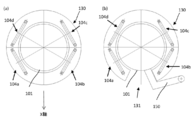
- Patent Document 1 discloses a technique for solving the above problems. The technique disclosed in Patent Document 1 will be described with reference to FIG. FIG. 14B shows a cross section taken along the line AA of FIG. 14A.
- the number of superconducting coils 104 is 4 or more (for example, 104a, 104b, 104c, 104d). 4), and arrange them on a flat surface in a tubular container coaxially provided around the pulling furnace, and set each superconducting coil arranged so as to face each other via the axis of the tubular container.
- the arrangement angle ⁇ see FIG.
- d is the diameter (inner diameter) of the superconducting coil
- l is the distance between the pair of coils.
- the magnetic field distribution applied to the molten single crystal material is made uniform and the unbalanced electromagnetic force is suppressed, so that thermal convection is suppressed even at a lower magnetic flux density as compared with the conventional technique using two coils. It came to be done.
- the convection suppression force due to the electromagnetic force is weakened in the upper part of the molten semiconductor material, and the cross section parallel to the X axis (cross section parallel to the magnetic field line) and the cross section perpendicular to the X axis (magnetic force line) Comparing the cross section perpendicular to the X-axis, the convection is stronger in the cross section perpendicular to the X-axis (in the cross section perpendicular to the magnetic field line).
- the magnetic flux density distribution on the X-axis is convex upward when the magnetic field line direction in the central axis of the pulling furnace is the X-axis in the horizontal plane including the coil axis of the superconducting coil.
- the magnetic flux density in the central axis in the horizontal plane is set as the magnetic flux density set value
- the magnetic flux density on the X-axis is 80% or less of the magnetic flux density set value in the wall of the wall, and at the same time, the horizontal plane.
- the magnetic flux density distribution on the Y-axis that is orthogonal to the X-axis and passes through the central axis is a downwardly convex distribution, and the magnetic flux density on the Y-axis is 140% or more of the magnetic flux density set value on the wall.
- two pairs of superconducting coils arranged so as to face each other are provided in the magnetic flux generator so that the respective coil shafts are included in the same horizontal plane, and the coil shafts are provided.
- the central angle ⁇ sandwiching the X-axis between them was set to 100 degrees or more and 120 degrees or less.
- the flow velocity of the molten single crystal material can be reduced even in the cross section perpendicular to the X axis where the convection suppression force due to the electromagnetic force is insufficient, and the flow velocity of the molten single crystal material in the cross section parallel to the X axis.
- the flow velocity in the cross section of the molten single crystal material perpendicular to the X axis can be balanced. Further, even in the cross section perpendicular to the X-axis, by reducing the flow velocity of the molten single crystal material, the time until the oxygen eluted from the crucible wall reaches the single crystal becomes longer, and the molten single crystal material becomes longer.
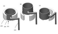
- a notch 131 is provided in the cylindrical container 105 on both or either side, and the chamber of the pulling furnace 101 is provided. Even if it can be raised and swiveled, the chamber of the pulling furnace 101 and the large graphite member must be raised so as to avoid the superconducting magnet 130 (magnet) and then taken out, resulting in poor work efficiency and poor work efficiency. Raising a heavy object to a high place (using the arm 150, see Fig. 16) takes time and effort, and it is also necessary to ensure safety. Therefore, it is necessary to lower the magnetic field generator before disassembling and setting. was there.
- the present invention has been made in view of the above problems, and it is not necessary to move the magnetic field generator at the time of disassembling and setting the single crystal pulling device, the oxygen concentration in the single crystal to be grown can be reduced, and the growing single crystal can be grown. It is an object of the present invention to provide a single crystal pulling device capable of suppressing growth fringes in a single crystal. Another object of the present invention is to provide a single crystal pulling method using such a single crystal pulling device.
- the present invention provides a pulling furnace having a central axis in which a heater and a pit containing a molten single crystal material are arranged, and a superconducting coil and the superconducting coil provided around the pulling furnace.
- a magnetic field generator having a cryostat with a built-in coil is provided, and a horizontal magnetic field is applied to the molten single crystal material by energizing the superconducting coil to suppress convection of the molten single crystal material in the pit.
- the single crystal pulling device for pulling a single crystal, the magnetic field generator has four superconducting coils, and all the coil shafts of the four superconducting coils are arranged so as to be contained in a single horizontal plane.
- the direction of the magnetic field line in the central axis in the horizontal plane is the X axis
- two each are divided into a first region and a second region divided by a cross section including the X axis and the central axis of the pulling furnace.
- the superconducting coils are arranged, the four superconducting coils are arranged line-symmetrically with respect to the cross section, and all of the four superconducting coils have the coil shafts of the X in the horizontal plane.
- the two superconducting coils provide a single crystal pulling device characterized in that the directions of the generated magnetic field lines are opposite.
- the superconducting coil can be arranged so that the magnetic field generator does not need to be moved when the single crystal pulling device is disassembled and set. Further, in the case of a single crystal pulling device provided with a magnetic field generator having such an arrangement of superconducting coils, the molten single crystal material is formed even in a cross section perpendicular to the X axis where the convection suppression force due to electromagnetic force is insufficient. The flow velocity of the molten single crystal material in the cross section parallel to the X axis and the flow velocity of the molten single crystal material in the cross section perpendicular to the X axis can be balanced.
- the magnetic field generator includes, as the cryostat, a U-shaped cryostat containing all the four superconducting coils, or the first region. It is preferable that the cryostats containing the two superconducting coils are provided in each of the second region and the second region, and the two cryostats have a structure in which they are structurally connected.
- the height of the superconducting coil in the vertical direction can be longer than the width of the superconducting coil seen from above in the vertical direction.
- the magnetic flux density in the central axis of the pulling furnace can be increased in the horizontal plane including the coil axis even if the width of the coil seen from above is narrow.
- the present invention also provides a single crystal pulling method characterized by pulling a silicon single crystal using any of the above single crystal pulling devices.
- the superconducting coil can be arranged so that the magnetic field generator does not need to be moved when the single crystal pulling device is disassembled and set.
- the single crystal pulling device of the present invention is a single crystal pulling device capable of significantly reducing the oxygen concentration taken into the single crystal and suppressing growth fringes in the growing single crystal. be able to. Further, according to the single crystal pulling method of the present invention, it is possible to grow a single crystal in which the oxygen concentration taken in is significantly reduced and the growth fringes are suppressed.
- (A) is a schematic view showing the result of magnetic field analysis by simulation in Example 1
- (b) is a schematic view showing the arrangement of superconducting coils in Example 1.
- (a) shows the velocity vector of the melt in the cross section perpendicular to a magnetic field
- (b) is perpendicular to a magnetic field.
- the oxygen concentration of the melt in the cross section is shown
- (c) shows the velocity vector of the melt in the cross section parallel to the magnetic field
- (d) shows the oxygen concentration of the melt in the cross section parallel to the magnetic field.
- (A) is a diagram showing the result of magnetic field analysis by simulation in Comparative Example 1
- (b) is a diagram showing the arrangement of superconducting coils in Comparative Example 1. It is a figure which shows the 3D melt convection analysis result which considered the magnetic field distribution by the simulation in Comparative Example 1, (a) shows the velocity vector of the melt in the cross section perpendicular to a magnetic field, and (b) is perpendicular to a magnetic field. The oxygen concentration of the melt in the cross section is shown, (c) shows the velocity vector of the melt in the cross section parallel to the magnetic field, and (d) shows the oxygen concentration of the melt in the cross section parallel to the magnetic field. ing.
- (A) is a diagram showing the result of magnetic field analysis by simulation in Comparative Example 2
- (b) is a diagram showing the arrangement of superconducting coils in Comparative Example 2.
- (a) shows the velocity vector of the melt in the cross section perpendicular to a magnetic field
- (b) is perpendicular to a magnetic field.
- the oxygen concentration of the melt in the cross section is shown
- (c) shows the velocity vector of the melt in the cross section parallel to the magnetic field
- (d) shows the oxygen concentration of the melt in the cross section parallel to the magnetic field.
- FIG. It is a schematic perspective view which shows an example of the superconducting magnet in the conventional single crystal pulling apparatus. It is a figure which shows the conventional magnetic flux density distribution. It is a schematic perspective view and the schematic cross-sectional view which shows the superconducting magnet of Patent Document 1.
- FIG. It is a schematic cross-sectional view which shows the superconducting magnet of Patent Document 2, (a) shows the case of a cylindrical container, and (b) shows the case where a part of a cylindrical container has a notch.
- the single crystal pulling device 21 of FIG. 1A is a pulling device having a central axis 20 in which a heating heater 13 and a magnetic field 12 containing a molten single crystal material (hereinafter, also simply referred to as “melt”) 16 are arranged.
- a magnetic field generator 30 having a furnace 11 and a superconducting coil provided around the pulling furnace 11 and a cryostat incorporating the superconducting coil is provided, and a horizontal magnetic field is applied to the melt 16 by energizing the superconducting coil.
- the single crystal 19 is pulled up in the pulling direction 18 while suppressing the convection of the melt 16 in the pit 12.
- the superconducting coil is arranged as shown in FIG. 1 (b).
- the magnetic field generator 30 has four superconducting coils.
- all the coil shafts of the four superconducting coils 14a, 14b, 14c, and 14d are arranged so as to be included in a single horizontal plane (horizontal plane 22 including the coil shaft shown in FIG. 1A). ..
- the direction of the magnetic field line 17 on the central axis 20 in the horizontal plane 22 is defined as the X axis
- the first region and the second region divided by the cross section including the X axis and the central axis 20 of the pulling furnace are respectively. Two superconducting coils are arranged. In FIG.
- the superconducting coil 14a and the superconducting coil 14d are arranged in the first region. ..
- a superconducting coil 14b and a superconducting coil 14c are arranged in the second region.
- the four superconducting coils 14a, 14b, 14c, and 14d are arranged line-symmetrically with respect to the cross section.
- FIG. 1B shows a state in which two superconducting coils arranged in each of the first region and the second region are arranged side by side in parallel with the X-axis.
- the directions of the lines of magnetic force generated by the four superconducting coils 14a, 14b, 14c, and 14d are line-symmetric with respect to the above cross section, as shown in FIG. 1 (b).
- the directions of the lines of magnetic force generated by the two superconducting coils are opposite to each other.
- the four superconducting coils 14a, 14b, 14c, and 14d are all more than -30 ° and less than 30 ° with respect to the Y axis whose coil axis is perpendicular to the X axis in the horizontal plane 22. It needs to be arranged so that it is within the range of angles.
- FIG. 2 shows an example of the coil arrangement (viewed from above) of the single crystal pulling device of the present invention.
- FIG. 2A shows a case where the coil axis is 0 ° with respect to the Y axis in the horizontal plane 22.
- the four superconducting coils 14a, 14b, 14c, 14d are parallel to the X axis, and the coil axis and the Y axis are parallel.
- FIG. 2B shows a case where the coil axis is 25 ° with respect to the Y axis in the horizontal plane 22.
- FIG. 2C shows a case where the coil axis is ⁇ 25 ° with respect to the Y axis in the horizontal plane 22.
- the coil axis and the Y axis intersect on the opposite side of the X axis of the superconducting coil, it is defined as a negative angle.
- the coil shaft is arranged so as to have an angle range of more than -30 ° and less than 30 ° with respect to the Y axis, it is possible to generate a predetermined magnetic field distribution.
- the flow velocity of the molten single crystal material can be reduced even in a cross section perpendicular to the X-axis, where the convection suppression force due to the electromagnetic force is conventionally insufficient.
- the flow velocity in the cross section of the molten single crystal material parallel to the X axis and the flow velocity in the cross section of the molten single crystal material perpendicular to the X axis can be balanced.
- the time until the oxygen eluted from the crucible wall reaches the single crystal becomes longer, and the molten single crystal material becomes longer.
- a single crystal pulling device capable of significantly reducing the oxygen concentration taken into the single crystal.
- the coil axis is arranged so as to have an angle range of more than -30 ° and less than 30 ° with respect to the Y axis, it is not necessary to move the magnetic field generator when disassembling and setting the single crystal pulling device. Can be an arrangement. If the coil axis is -30 ° or less or 30 ° or more with respect to the Y axis, the width of the cryostat containing the superconducting coil becomes large, or the distance between the superconducting coils becomes large. Is shortened, and it becomes necessary to raise and lower the magnetic field generator to disassemble and set the graphite parts as in the conventional case, which becomes a problem.
- the angle of the coil axis is preferably -5 ° or less with respect to the Y axis.
- the cryostat for creating a superconducting state has a U-shape containing all four superconducting coils 14a, 14b, 14c, and 14d as shown in FIG. 3A.
- a cryostat 31 can be provided.
- a cryostat containing two superconducting coils in each of the first region and the second region may be provided, and the two cryostats may have a structure in which they are structurally connected.
- FIG. 3 (b) An example of a cryostat of this aspect is shown in FIG. 3 (b).
- two superconducting coils 14a and 14d are incorporated in the first cryostat 32 in the first region, and two superconducting coils 14b and 14c are incorporated in the second cryostat 33 in the second region.
- first cryostat 32 and the second cryostat 33 are structurally connected by a structural member 34.
- the height of the superconducting coil in the vertical direction is longer than the width of the superconducting coil seen from above in the vertical direction.
- FIGS. 4A and 4B show this superconducting coil.
- FIG. 4A shows a cross section of the superconducting coil
- FIG. 4B shows a state in which FIG. 4A is turned sideways
- the height of the superconducting coil is indicated by H.
- the direction of H is up and down in the vertical direction.
- R is the radius of curvature of the curved portion (arc) of the superconducting coil.
- the silicon single crystal can be pulled up by using the single crystal pulling device of the present invention. With such a single crystal pulling method, it is possible to grow a silicon single crystal in which the oxygen concentration taken in is significantly reduced and the growth fringes are suppressed.
- Example 1 It has two pairs (4) of coils with a vertical arc radius of 250 mm and a height of 1000 mm, and the direction of the magnetic field line in the horizontal plane including the coil axes of the two pairs (4) superconducting coils is defined as the X axis.
- two superconducting coils, one pair each on the left and right (first region and second region), are arranged parallel to the X-axis with respect to the cross section including the X-axis and the central axis of the hoisting furnace.
- a magnetic field analysis and a 3D melt convection analysis were performed on the magnetic field generating ground device arranged line-symmetrically with respect to the cross section, and then the silicon single crystal was pulled up using this device.
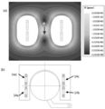
- FIG. 5A shows the result of magnetic field analysis by ANSYS-Maxwell3D. After adjusting and analyzing the coil current ⁇ number of turns so that the magnetic flux density on the central axis is 1000 gauss (0.1 tesla), the magnetic flux This is a display of the density distribution.
- FIG. 5B is a schematic view showing the arrangement of the four superconducting coils 14a, 14b, 14c, and 14d at this time.
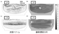
- 6 (a) and 6 (c) are velocity vectors in the melt obtained from the results (FIG. 6 (a) is a cross section perpendicular to the magnetic field, and FIG. 6 (c) is a cross section parallel to the magnetic field.
- 6 (b) and (d) show the oxygen concentration distribution in the melt (FIG. 6 (b) is a cross section perpendicular to the magnetic field, and FIG. 6 (d) is a cross section parallel to the magnetic field. ).
- the calculation conditions at that time were a charge amount of 400 kg, a 32 inch (1 inch is 25.4 mm) crucible, a silicon crystal with a diameter of 306 mm, a crystal rotation of 9 rpm, a crucible rotation of 0.4 rpm, and a pulling speed of 0.4 mm / min. ..
- Example 1 In the magnetic field of Example 1, similarly to Comparative Example 2 described later, the convection inhibition force is strong even in the cross section perpendicular to the magnetic field line, and a relatively active flow can be seen only under the crystal edge, and oxygen in the melt is observed. The concentration is also low.
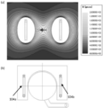
- FIG. 7A shows the result of magnetic field analysis by ANSYS-Maxwell3D. After adjusting and analyzing the coil current ⁇ number of turns so that the magnetic flux density on the central axis is 1000 gauss (0.1 tesla), the magnetic flux This is a display of the density distribution. Note that FIG. 7B is a schematic view showing the arrangement of the two superconducting coils 104a and 104b at this time.
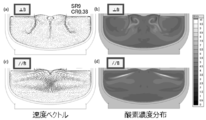
- FIGS. 8 (b) and 8 (d) show the oxygen concentration distribution in the melt (FIG. 8 (b) is a cross section perpendicular to the magnetic field, and FIG. 8 (d) is a cross section parallel to the magnetic field. It is.).
- a vigorous vortex flow with a weak convective inhibition force is generated in a cross section perpendicular to the magnetic field line, and the oxygen concentration in the melt is also high.
- FIG. 9A shows the result of magnetic field analysis by ANSYS-Maxwell3D. After adjusting and analyzing the coil current ⁇ number of turns so that the magnetic flux density on the central axis is 1000 gauss (0.1 tesla), the magnetic flux This is a display of the density distribution.
- FIG. 9B is a schematic view showing the arrangement of the four superconducting coils 104a, 104b, 104c, and 104d at this time.
- FIGS. 10 (b) and 10 (d) show the oxygen concentration distribution in the melt (FIG. 10 (b) is a cross section perpendicular to the magnetic field, and FIG. 10 (d) is a cross section parallel to the magnetic field. .).
- Example 1 The calculation conditions at that time were the same as in Example 1 and Comparative Example 1, with a charge amount of 400 kg, a crucible of 32 inches (1 inch is 25.4 mm), a silicon crystal having a diameter of 306 mm, a crystal rotation of 9 rpm, and a crucible rotation of 0.4 rpm. It was calculated assuming a pulling speed of 0.4 mm / min.
- the present invention is not limited to the above embodiment.
- the above embodiment is an example, and any one having substantially the same configuration as the technical idea described in the claims of the present invention and exhibiting the same effect and effect is the present invention. It is included in the technical scope of the invention.
Landscapes
- Chemical & Material Sciences (AREA)
- Engineering & Computer Science (AREA)
- Crystallography & Structural Chemistry (AREA)
- Materials Engineering (AREA)
- Metallurgy (AREA)
- Organic Chemistry (AREA)
- Crystals, And After-Treatments Of Crystals (AREA)
Abstract
Description
上下円弧の半径が250mm、高さ1000mmのコイルを2対(4個)有し、該2対(4個)の超電導コイルのコイル軸を含む水平面内の前記中心軸における磁力線方向をX軸としたときに、このX軸と引き上げ炉の中心軸を含む断面に対して、左右(第1の領域及び第2の領域)にそれぞれ一対各々2個の超電導コイルをX軸と平行に並べ、該断面に対して線対称に配置した磁場発生地装置について、磁場解析と3D融液対流解析を行った後、この装置を用いてシリコン単結晶の引き上げを行った。
外径1100mmの一対(2個)のコイルを引上げ機の中心軸に対して左右対称に配置した磁場発生装置について、磁場解析と3D融液対流解析を行った後、この装置を用いてシリコン単結晶の引き上げを行った。
コイル軸を含む水平面内において、引上げ機の中心軸における磁力線方向をX軸としたときに、対向配置された直径900mmのコイルの対をそれぞれのコイル軸が同じ水平面内に含まれるように2対(4個)設けるとともに、前記X軸を挟むコイル軸間角度αを120度として円筒容器内に配置した磁場発生装置について、磁場解析と3D融液対流解析を行った後、この装置を用いてシリコン単結晶の引き上げを行った。
Claims (4)
- 加熱ヒーター及び溶融した単結晶材料が収容される坩堝が配置され中心軸を有する引き上げ炉と、
前記引き上げ炉の周囲に設けられ、超電導コイルと該超電導コイルを内蔵するクライオスタットを有する磁場発生装置とを備え、
前記超電導コイルへの通電により前記溶融した単結晶材料に水平磁場を印加して、前記溶融した単結晶材料の前記坩堝内での対流を抑制する単結晶引き上げ装置であって、
前記磁場発生装置は、前記超電導コイルを4個有し、前記4個の超電導コイルの全てのコイル軸が単一の水平面内に含まれるように配置されており、
前記水平面内の前記中心軸における磁力線方向をX軸としたときに、該X軸と前記引き上げ炉の中心軸を含む断面で分けられる第1の領域及び第2の領域に、それぞれ2個ずつの前記超電導コイルが配置されており、
前記4個の超電導コイルは、前記断面に対して線対称に配置されており、
前記4個の超電導コイルは、いずれもコイル軸が前記水平面内において前記X軸と垂直なY軸に対して-30°超30°未満の角度の範囲となるよう配置されており、
前記4個の超電導コイルが発生する磁力線の方向は、前記断面に対して線対称であり、
前記第1の領域及び第2の領域のそれぞれにおいて、2個の前記超電導コイルは、発生する磁力線の方向が逆であることを特徴とする単結晶引き上げ装置。 - 前記磁場発生装置は、前記クライオスタットとして、前記4個の超電導コイルを全て内蔵するコの字型形状のクライオスタットを備えるか、又は、前記第1の領域及び第2の領域のそれぞれにおいて2個の前記超電導コイルを内蔵するクライオスタットを備え、該2個のクライオスタットが構造的に連結された構造を有するものであることを特徴とする請求項1に記載の単結晶引き上げ装置。
- 前記超電導コイルは、鉛直方向上方から見た該超電導コイルの幅よりも、該超電導コイルの鉛直方向の高さの方が長いものであることを特徴とする請求項1又は請求項2に記載の単結晶引き上げ装置。
- 請求項1から請求項3に記載の単結晶引き上げ装置を用いて、シリコン単結晶を引き上げることを特徴とする単結晶引き上げ方法。
Priority Applications (4)
| Application Number | Priority Date | Filing Date | Title |
|---|---|---|---|
| KR1020217035490A KR102808358B1 (ko) | 2019-05-08 | 2020-03-19 | 단결정 인상장치 및 단결정 인상방법 |
| DE112020001801.6T DE112020001801B4 (de) | 2019-05-08 | 2020-03-19 | Einkristall-Zieh-Vorrichtung und Einkristall-Zieh-Verfahren |
| US17/605,399 US12227872B2 (en) | 2019-05-08 | 2020-03-19 | Single-crystal pulling apparatus and single-crystal pulling method |
| CN202080033333.8A CN113811642A (zh) | 2019-05-08 | 2020-03-19 | 单晶提拉装置及单晶提拉方法 |
Applications Claiming Priority (2)
| Application Number | Priority Date | Filing Date | Title |
|---|---|---|---|
| JP2019-088473 | 2019-05-08 | ||
| JP2019088473A JP7070500B2 (ja) | 2019-05-08 | 2019-05-08 | 単結晶引き上げ装置及び単結晶引き上げ方法 |
Publications (1)
| Publication Number | Publication Date |
|---|---|
| WO2020225985A1 true WO2020225985A1 (ja) | 2020-11-12 |
Family
ID=73044562
Family Applications (1)
| Application Number | Title | Priority Date | Filing Date |
|---|---|---|---|
| PCT/JP2020/012164 Ceased WO2020225985A1 (ja) | 2019-05-08 | 2020-03-19 | 単結晶引き上げ装置及び単結晶引き上げ方法 |
Country Status (6)
| Country | Link |
|---|---|
| US (1) | US12227872B2 (ja) |
| JP (1) | JP7070500B2 (ja) |
| KR (1) | KR102808358B1 (ja) |
| CN (1) | CN113811642A (ja) |
| DE (1) | DE112020001801B4 (ja) |
| WO (1) | WO2020225985A1 (ja) |
Cited By (1)
| Publication number | Priority date | Publication date | Assignee | Title |
|---|---|---|---|---|
| WO2023100539A1 (ja) * | 2021-11-30 | 2023-06-08 | 株式会社Sumco | 単結晶の製造装置用磁石、単結晶の製造装置および単結晶の製造方法 |
Families Citing this family (3)
| Publication number | Priority date | Publication date | Assignee | Title |
|---|---|---|---|---|
| JP7548081B2 (ja) * | 2021-03-15 | 2024-09-10 | 信越半導体株式会社 | 単結晶引上げ装置および単結晶引上げ方法 |
| JP7683468B2 (ja) * | 2021-11-30 | 2025-05-27 | 株式会社Sumco | 単結晶の製造方法 |
| CN116759188B (zh) * | 2023-08-15 | 2023-11-03 | 苏州八匹马超导科技有限公司 | 一种超导磁体 |
Citations (5)
| Publication number | Priority date | Publication date | Assignee | Title |
|---|---|---|---|---|
| JP2000182823A (ja) * | 1998-12-14 | 2000-06-30 | Mitsubishi Electric Corp | 電磁石装置 |
| JP2004051475A (ja) * | 2002-05-31 | 2004-02-19 | Toshiba Corp | 単結晶引上げ装置、超電導磁石および単結晶引上げ方法 |
| JP2005123313A (ja) * | 2003-10-15 | 2005-05-12 | Sumitomo Heavy Ind Ltd | 単結晶引上げ装置用超電導磁石装置における冷凍機の装着構造及び冷凍機のメンテナンス方法 |
| US20140053771A1 (en) * | 2012-08-21 | 2014-02-27 | Babcock Noell Gmbh | Generating a Homogeneous Magnetic Field While Pulling a Single Crystal from Molten Semiconductor Material |
| WO2017047008A1 (ja) * | 2015-09-18 | 2017-03-23 | 信越半導体株式会社 | 単結晶引き上げ装置及び単結晶引き上げ方法 |
Family Cites Families (4)
| Publication number | Priority date | Publication date | Assignee | Title |
|---|---|---|---|---|
| JP3592467B2 (ja) * | 1996-11-14 | 2004-11-24 | 株式会社東芝 | 単結晶引上げ装置用超電導磁石 |
| EP1224671A1 (en) * | 1999-09-21 | 2002-07-24 | Magnetic Solutions ( Holdings) Limited | A device for generating a variable magnetic field |
| JP5057941B2 (ja) | 2007-11-22 | 2012-10-24 | 株式会社東芝 | 超電導マグネット装置 |
| JP2010100474A (ja) | 2008-10-23 | 2010-05-06 | Covalent Materials Corp | シリコン単結晶引上げ水平磁場の最適化方法およびシリコン単結晶の製造方法 |
-
2019
- 2019-05-08 JP JP2019088473A patent/JP7070500B2/ja active Active
-
2020
- 2020-03-19 US US17/605,399 patent/US12227872B2/en active Active
- 2020-03-19 KR KR1020217035490A patent/KR102808358B1/ko active Active
- 2020-03-19 DE DE112020001801.6T patent/DE112020001801B4/de active Active
- 2020-03-19 WO PCT/JP2020/012164 patent/WO2020225985A1/ja not_active Ceased
- 2020-03-19 CN CN202080033333.8A patent/CN113811642A/zh active Pending
Patent Citations (5)
| Publication number | Priority date | Publication date | Assignee | Title |
|---|---|---|---|---|
| JP2000182823A (ja) * | 1998-12-14 | 2000-06-30 | Mitsubishi Electric Corp | 電磁石装置 |
| JP2004051475A (ja) * | 2002-05-31 | 2004-02-19 | Toshiba Corp | 単結晶引上げ装置、超電導磁石および単結晶引上げ方法 |
| JP2005123313A (ja) * | 2003-10-15 | 2005-05-12 | Sumitomo Heavy Ind Ltd | 単結晶引上げ装置用超電導磁石装置における冷凍機の装着構造及び冷凍機のメンテナンス方法 |
| US20140053771A1 (en) * | 2012-08-21 | 2014-02-27 | Babcock Noell Gmbh | Generating a Homogeneous Magnetic Field While Pulling a Single Crystal from Molten Semiconductor Material |
| WO2017047008A1 (ja) * | 2015-09-18 | 2017-03-23 | 信越半導体株式会社 | 単結晶引き上げ装置及び単結晶引き上げ方法 |
Cited By (4)
| Publication number | Priority date | Publication date | Assignee | Title |
|---|---|---|---|---|
| WO2023100539A1 (ja) * | 2021-11-30 | 2023-06-08 | 株式会社Sumco | 単結晶の製造装置用磁石、単結晶の製造装置および単結晶の製造方法 |
| JP2023081196A (ja) * | 2021-11-30 | 2023-06-09 | 株式会社Sumco | 単結晶の製造装置用磁石、単結晶の製造装置および単結晶の製造方法 |
| TWI822373B (zh) * | 2021-11-30 | 2023-11-11 | 日商Sumco股份有限公司 | 單結晶的製造裝置用磁石、單結晶的製造裝置及單結晶的製造方法 |
| JP7786165B2 (ja) | 2021-11-30 | 2025-12-16 | 株式会社Sumco | 単結晶の製造装置用磁石、単結晶の製造装置および単結晶の製造方法 |
Also Published As
| Publication number | Publication date |
|---|---|
| KR102808358B1 (ko) | 2025-05-16 |
| US12227872B2 (en) | 2025-02-18 |
| CN113811642A (zh) | 2021-12-17 |
| DE112020001801B4 (de) | 2026-03-12 |
| US20230175166A1 (en) | 2023-06-08 |
| DE112020001801T5 (de) | 2022-01-20 |
| JP2020183334A (ja) | 2020-11-12 |
| JP7070500B2 (ja) | 2022-05-18 |
| KR20220006513A (ko) | 2022-01-17 |
Similar Documents
| Publication | Publication Date | Title |
|---|---|---|
| JP6436031B2 (ja) | 単結晶引き上げ装置、及び単結晶引き上げ方法 | |
| JP7070500B2 (ja) | 単結晶引き上げ装置及び単結晶引き上げ方法 | |
| US11578423B2 (en) | Magnet coil for magnetic czochralski single crystal growth and magnetic czochralski single crystal growth method | |
| JP2004051475A (ja) | 単結晶引上げ装置、超電導磁石および単結晶引上げ方法 | |
| JP6620670B2 (ja) | 単結晶引き上げ装置及び単結晶引き上げ方法 | |
| US20240141548A1 (en) | Single crystal pulling apparatus and method for pulling single crystal | |
| JP7439900B2 (ja) | 単結晶引上げ装置および単結晶引上げ方法 | |
| JP7160006B2 (ja) | 単結晶引上げ装置および単結晶引上げ方法 | |
| JP7230781B2 (ja) | 単結晶引き上げ装置及び単結晶引き上げ方法 | |
| JP3585731B2 (ja) | 磁界印加式単結晶製造装置 | |
| WO2022163091A1 (ja) | 単結晶引上げ装置および単結晶引上げ方法 | |
| JPS6270286A (ja) | 単結晶製造装置 | |
| JPS6278184A (ja) | 単結晶育成装置 |
Legal Events
| Date | Code | Title | Description |
|---|---|---|---|
| 121 | Ep: the epo has been informed by wipo that ep was designated in this application |
Ref document number: 20802119 Country of ref document: EP Kind code of ref document: A1 |
|
| ENP | Entry into the national phase |
Ref document number: 20217035490 Country of ref document: KR Kind code of ref document: A |
|
| WWE | Wipo information: entry into national phase |
Ref document number: 112020001801 Country of ref document: DE |
|
| 122 | Ep: pct application non-entry in european phase |
Ref document number: 20802119 Country of ref document: EP Kind code of ref document: A1 |
|
| WWC | Wipo information: continuation of processing after refusal or withdrawal |
Ref document number: 1020217035490 Country of ref document: KR |
|
| WWG | Wipo information: grant in national office |
Ref document number: 112020001801 Country of ref document: DE |