WO2020218243A1 - 低硫黄石炭の製造方法 - Google Patents
低硫黄石炭の製造方法 Download PDFInfo
- Publication number
- WO2020218243A1 WO2020218243A1 PCT/JP2020/017060 JP2020017060W WO2020218243A1 WO 2020218243 A1 WO2020218243 A1 WO 2020218243A1 JP 2020017060 W JP2020017060 W JP 2020017060W WO 2020218243 A1 WO2020218243 A1 WO 2020218243A1
- Authority
- WO
- WIPO (PCT)
- Prior art keywords
- coal
- hydrogen peroxide
- sulfur
- chemical
- producing low
- Prior art date
- Legal status (The legal status is an assumption and is not a legal conclusion. Google has not performed a legal analysis and makes no representation as to the accuracy of the status listed.)
- Ceased
Links
Images


Classifications
-
- C—CHEMISTRY; METALLURGY
- C10—PETROLEUM, GAS OR COKE INDUSTRIES; TECHNICAL GASES CONTAINING CARBON MONOXIDE; FUELS; LUBRICANTS; PEAT
- C10L—FUELS NOT OTHERWISE PROVIDED FOR; NATURAL GAS; SYNTHETIC NATURAL GAS OBTAINED BY PROCESSES NOT COVERED BY SUBCLASSES C10G OR C10K; LIQUIFIED PETROLEUM GAS; USE OF ADDITIVES TO FUELS OR FIRES; FIRE-LIGHTERS
- C10L5/00—Solid fuels
- C10L5/02—Solid fuels such as briquettes consisting mainly of carbonaceous materials of mineral or non-mineral origin
- C10L5/04—Raw material of mineral origin to be used; Pretreatment thereof
-
- C—CHEMISTRY; METALLURGY
- C10—PETROLEUM, GAS OR COKE INDUSTRIES; TECHNICAL GASES CONTAINING CARBON MONOXIDE; FUELS; LUBRICANTS; PEAT
- C10B—DESTRUCTIVE DISTILLATION OF CARBONACEOUS MATERIALS FOR PRODUCTION OF GAS, COKE, TAR, OR SIMILAR MATERIALS
- C10B57/00—Other carbonising or coking processes; Features of destructive distillation processes in general
- C10B57/08—Non-mechanical pretreatment of the charge, e.g. desulfurization
-
- C—CHEMISTRY; METALLURGY
- C10—PETROLEUM, GAS OR COKE INDUSTRIES; TECHNICAL GASES CONTAINING CARBON MONOXIDE; FUELS; LUBRICANTS; PEAT
- C10L—FUELS NOT OTHERWISE PROVIDED FOR; NATURAL GAS; SYNTHETIC NATURAL GAS OBTAINED BY PROCESSES NOT COVERED BY SUBCLASSES C10G OR C10K; LIQUIFIED PETROLEUM GAS; USE OF ADDITIVES TO FUELS OR FIRES; FIRE-LIGHTERS
- C10L9/00—Treating solid fuels to improve their combustion
- C10L9/02—Treating solid fuels to improve their combustion by chemical means
- C10L9/06—Treating solid fuels to improve their combustion by chemical means by oxidation
-
- C—CHEMISTRY; METALLURGY
- C10—PETROLEUM, GAS OR COKE INDUSTRIES; TECHNICAL GASES CONTAINING CARBON MONOXIDE; FUELS; LUBRICANTS; PEAT
- C10L—FUELS NOT OTHERWISE PROVIDED FOR; NATURAL GAS; SYNTHETIC NATURAL GAS OBTAINED BY PROCESSES NOT COVERED BY SUBCLASSES C10G OR C10K; LIQUIFIED PETROLEUM GAS; USE OF ADDITIVES TO FUELS OR FIRES; FIRE-LIGHTERS
- C10L2290/00—Fuel preparation or upgrading, processes or apparatus therefore, comprising specific process steps or apparatus units
- C10L2290/44—Deacidification step, e.g. in coal enhancing
Definitions
- the present invention relates to a method for producing low sulfur coal.
- coal When coal is used as a reducing agent for iron ore in the steelmaking process, some sulfur contained in the coal dissolves in the iron obtained by reducing the iron ore. Since residual sulfur deteriorates the toughness and workability of steel materials, great efforts have been made to remove sulfur from iron. In addition, when coal is used as a heat source, sulfur oxides are mixed in the exhaust gas, and therefore, from the viewpoint of preventing air pollution, great efforts are required to remove sulfur from the exhaust gas.
- an object of the present invention is to provide a method for producing low-sulfur coal having an excellent desulfurization effect.
- the present invention provides the following [1] to [16].
- [1] A method for producing low-sulfur coal, which removes sulfur in the coal by contacting the coal with a chemical which is a mixed solution of hydrogen peroxide and acetic acid.
- [2] The method for producing low-sulfur coal according to the above [1], wherein the molar ratio of the acetic acid to the hydrogen peroxide (acetic acid / hydrogen peroxide) is 1.2 or more and 60.0 or less.
- the acetic acid and the hydrogen peroxide are mixed.
- the method for producing low-sulfur coal of the present invention removes sulfur in the coal by contacting the coal with a chemical which is a mixed solution of hydrogen peroxide and acetic acid. It is a method for producing low-sulfur coal to be removed. Further, the method of the present invention is a method for producing low-sulfur coal, which removes sulfur in the coal by contacting the coal with a chemical which is an aqueous solution of peracetic acid. Further, the method of the present invention is a method for producing low-sulfur coal, which removes sulfur in the coal by contacting the coal with a chemical which is a mixed solution of hydrogen peroxide and formic acid.
- Sulfur in coal is roughly classified into inorganic sulfur (inorganic sulfur content) and organic sulfur (organic sulfur content).
- FeS 2 is a typical example of inorganic sulfur.
- organic sulfur include aromatic sulfur compounds in which sulfur is present inside the aromatic ring such as dibenzothiophene; and aliphatic sulfur compounds such as mercaptan; Of these, sulfur existing inside the aromatic ring constituting coal is known to be particularly difficult to remove.
- peracetic acid effectively acts on thiophene-like sulfur, which is a particularly difficult component of organic sulfur in coal, thereby converting sulfur into a form that can or is easily removed from coal.
- thiophene sulfur is oxidized to, for example, sulfone sulfur or sulfide sulfur, and the bond between carbon and sulfur is relatively weakened and the bond is easily broken, so that sulfur is easily desorbed. Will be done.
- peracetic acid CH 3 COO 2 H
- H 2 O 2 hydrogen peroxide
- CH 3 COOH acetic acid
- such a mixed solution or an aqueous solution of peracetic acid is used as a drug, and the drug is brought into contact with coal.
- the easily removable inorganic sulfur dissolves and leaches into the drug in the form of, for example, sulfate ions.
- some organic sulfur is also oxidized and leached into the drug in the form of sulfate ions and the like.
- the coal is desulfurized (ie, the sulfur in the coal is removed) to give a low sulfurized coal (low sulfur coal).
- a mixed solution of hydrogen peroxide and formic acid (hereinafter, also simply referred to as “mixed solution”) is used as a drug.
- the mixed solution produces performic acid (HCOO 2 H), which is a reaction product of hydrogen peroxide (H 2 O 2 ) and formic acid (HCOOH), by a reaction represented by the following formula (II).
- Such a mixed solution is brought into contact with coal.
- ⁇ Mole ratio (acetic acid / hydrogen peroxide) When a mixed solution of acetic acid and hydrogen peroxide is used as the drug, the molar ratio of acetic acid to hydrogen peroxide (acetic acid / hydrogen peroxide) in the drug is such that the reaction product peracetic acid is an appropriate amount and the desulfurization effect is more effective. For the reason of superiority, 1.2 or more is preferable, and 5.0 or more is more preferable. Further, when the molar ratio (acetic acid / hydrogen peroxide) is in this range, it is possible to suppress the excess of acetic acid with respect to hydrogen peroxide and the residual hydrogen peroxide in the mixed solution (as will be described later). Hydrogen peroxide reduces the carbon yield of coal).
- the molar ratio (acetic acid / hydrogen peroxide) is preferably 60.0 or less, more preferably 20.0 or less.
- the amount of peracetic acid, which is a reaction product becomes appropriate as described above, and the desulfurization effect is more excellent. Furthermore, it is suppressed that the produced peracetic acid is diluted with excess acetic acid.
- Li Amount of i aqueous solution [g / h]
- Ci Concentration of i aqueous solution [mass%]
- Mi Molecular weight of i [g / mol]
- i represents acetic acid when it is 1, and hydrogen peroxide when it is 2.
- the molecular weight of acetic acid is 60, and the molecular weight of hydrogen peroxide is 34.
- the amount Li of the aqueous solution is adjusted so that the desired molar ratio (acetic acid / hydrogen peroxide) is obtained.
- the molar ratio of formic acid to hydrogen peroxide (formic acid / hydrogen peroxide) in the drug is preferably 1.2 or more, more preferably 5.0 or more. .. On the other hand, 60.0 or less is preferable, and 20.0 or less is more preferable. The reason is the same as when a mixed solution of acetic acid and hydrogen peroxide is used as a drug.
- the two substances that react are 1 mol each. Therefore, the molar amount (molar ratio) of the reactant required for the production of performic acid is the same.
- the method for determining the molar ratio (formic acid / hydrogen peroxide) is described in the above formulas (a) and (b). Replace "acetic acid” with "formic acid”.
- Formic acid has a molecular weight of 46.
- the elapsed time after mixing acetic acid and hydrogen peroxide is more preferably 45 minutes or more, and even more preferably 60 minutes or more. On the other hand, 120 minutes or less is preferable, and 80 minutes or less is more preferable.
- the reaction of the above formula (II) (forward reaction) is faster than the reaction of the above formula (I). Therefore, the time elapsed after mixing and before contacting with coal may be shorter than that in the case of mixing acetic acid and hydrogen peroxide.
- the elapsed time after mixing the formic acid and hydrogen peroxide is preferably 5 minutes or more, more preferably 6 minutes or more. On the other hand, 90 minutes or less is preferable, and 60 minutes or less is more preferable.
- the content of peracetic acid in the drug is preferably 1.0% by mass or more, preferably 5.0% by mass or more, because the desulfurization effect is more excellent. More preferably, 10.0% by mass or more.
- the content of peracetic acid in the drug (peracetic acid aqueous solution) is preferably 25.0% by mass or less.
- Peracetic acid has a risk of ignition on the high concentration side, but within this range, it can be safely and sufficiently desulfurized.
- FIG. 1 is a graph showing the desulfurization rate with respect to the mass ratio of chemicals and coal (drugs / coal). As shown in the graph of FIG. 1, when the amount of the chemical is larger than the amount of coal, the desulfurization rate is high and the desulfurization effect is more excellent. Therefore, the mass ratio (drug / coal) is preferably 0.5 or more, more preferably 1.0 or more.
- the mass ratio (drug / coal) is preferably 100.0 or less, more preferably 50.0 or less.
- the desulfurization rate [mass%] is W 1 [kg] for the mass of coal (solid content) before desulfurization,% S 1 [mass%] for the sulfur content of coal (solid content) before desulfurization, and after desulfurization.
- W 2 [kg] and the sulfur content of coal (solid content) after desulfurization is% S 2 [mass%]
- Desulfurization rate [mass%] 100 ⁇ ⁇ 1- (W 2 ⁇ % S 2 ) / (W 1 ⁇ % S 1 ) ⁇ ... (1)
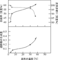
- FIG. 2 is a graph (lower) showing the amount of peracetic acid produced with respect to the temperature of the drug, and a graph (upper) showing the desulfurization rate (solid line) and carbon yield (broken line) with respect to the temperature of the drug.
- the amount of peracetic acid produced is an index with the calculated value of 1.0 when the reaction contributing substances (hydrogen peroxide and acetic acid) have completely reacted.
- the temperature of the drug is preferably 5 ° C. or higher, more preferably 10 ° C. or higher, further preferably 20 ° C. or higher, and particularly preferably 50 ° C. or higher.
- the temperature of the drug does not become too high in order to maintain the carbon yield high.
- 65 ° C. or lower is preferable, 60 ° C. or lower is more preferable, and 55 ° C. or lower is further preferable, because the carbon yield is excellent.
- Carbon yield [mass%] 100 ⁇ (W 2 ⁇ % C 2 ) / (W 1 ⁇ % C 1 )... (2)
- the coal used in the present invention is not particularly limited, and a wide variety of coals can be used, but it is preferable to include coal having a moderate degree of coalification such as subbituminous coal, more preferably to contain subbituminous coal, and subbituminous coal. Is more preferable.
- the desulfurization effect tends to be superior to that when coal with a high degree of coalification such as anthracite is used, and when coal with a low degree of coalification such as lignite is used. It tends to have excellent carbon yield.
- the particle size (average particle size) of coal used in the present invention is not particularly limited. For example, even if the particle size of coal is about several millimeters, there is no significant change in desulfurization performance. If the grain size of the coal is larger than this, a light pulverization treatment may be performed, if necessary.
- the primary treatment (chemical treatment) for desulfurizing coal has been described above.
- two types of secondary treatments will be described as treatments for further removing sulfur remaining in the coal desulfurized by the primary treatment.
- the heat treatment temperature is preferably 150 ° C. or higher, more preferably 250 ° C. or higher, and even more preferably 350 ° C. or higher.
- hydrocarbon-containing hydrocarbon-containing gas derived from coal generated by the heat treatment can be recovered and used as a part of the gaseous fuel in the steelmaking process.
- heat treatment using waste heat generated in a factory such as a steel mill, heat treatment at a temperature of up to several hundred ° C. is preferable.
- the heat treatment temperature in the coke oven is about 1000 to 1200 ° C., and some operations are performed at 1200 ° C. or higher.
- Coal desulfurized in contact with a chemical may be introduced into a coke oven to produce low sulfur coke.
- a hydrocarbon gas and a sulfur-containing gas are generated, but the sulfur-containing gas may be removed separately.
- the generated gas after removing the sulfur-containing gas can be reused as a fuel gas.
- the highest temperature is considered to be substantially the coke manufacturing process.
- the heat treatment temperature is, for example, 1300 ° C. or lower.
- Coal heat-treated at about 600 ° C is generally called semi-coke.
- Coal desulfurized in contact with chemicals can also be used in the production of semi-coke.
- Semi-coke is generally inferior in strength to coke, so it is difficult to use as blast furnace coke, but it can be used for other purposes.
- semi-coke containing a small amount of sulfur is useful as, for example, a heating agent (carbonizing material) used for raising the temperature in a converter.
- the rate of temperature rise when raising the temperature of coal in contact with the chemical to the heat treatment temperature is high.
- the sulfur compound that has been transformed into a form that is easy to desulfurize by the action of peracetic acid or performic acid may be resynthesized into thiophene sulfur, which is difficult to desulfurize under heating, and this resynthesis is suppressed. is there.
- the rate of temperature rise is preferably 10 ° C./min or higher, more preferably 20 ° C./min or higher.
- the upper limit of the temperature rise rate is not particularly limited, but it is technically and industrially (cost-wise) difficult to realize a temperature rise rate that is too fast. Therefore, the rate of temperature rise is, for example, 100 ° C./min or less.
- the temperature of the hydrogen peroxide solution is preferably 50 ° C. or lower, more preferably 40 ° C. or lower. Hydrogen peroxide gradually increases its oxidizing power as the temperature rises, and tends to reduce not only the desulfurization effect but also the carbon yield. When the temperature of the hydrogen peroxide solution is within the above range, the desulfurization effect is further excellent and the carbon yield is also good.
- the lower limit is not particularly limited, and the temperature of the hydrogen peroxide solution is, for example, 5 ° C. or higher.
- the concentration of the hydrogen peroxide solution (content of hydrogen peroxide in the hydrogen peroxide solution) is preferably 2.0% by mass or more, more preferably 3.0% by mass or more, because the desulfurization effect is further excellent.
- concentration of the hydrogen peroxide solution is 3.0% by mass or more, the obtained effect is almost constant regardless of the concentration of the hydrogen peroxide solution. Therefore, the upper limit is not particularly limited, but for example, the concentration of the hydrogen peroxide solution is preferably 35.0% by mass or less. Since hydrogen peroxide is easily decomposed on the high concentration side, it is often marketed as an aqueous solution of 30 to 35% by mass. In the present invention, such a commercially available aqueous solution may be appropriately diluted before use.
- FIG. 3 is a schematic view showing an example of a low-sulfur coal manufacturing facility (hereinafter, also simply referred to as “manufacturing facility”).
- the manufacturing facility shown in FIG. 3 has a hydrogen peroxide storage tank 1 for storing hydrogen peroxide and an acetic acid storage tank 3 for storing acetic acid.
- the hydrogen peroxide inside the hydrogen peroxide storage tank 1 is supplied to the chemical mixing tank 5 via the hydrogen peroxide transport pipe 2.
- the acetic acid inside the acetic acid storage tank 3 is supplied to the drug mixing tank 5 via the acetic acid transport pipe 4.
- An appropriate flow rate control device (not shown) is installed in each of the hydrogen peroxide transport pipe 2 and the acetic acid transport pipe 4, and the flow rates of hydrogen peroxide and acetic acid can be controlled.
- a heating device 6 and a mixing device 7 are installed in the chemical mixing tank 5.
- the hydrogen peroxide and acetic acid supplied to the chemical mixing tank 5 are heated to a predetermined temperature by using the heating device 6 as needed, and are mixed by using the mixing device 7.
- the drug which is a mixed solution obtained by mixing in the drug mixing tank 5, is supplied to the desulfurization treatment tank 9 via the drug transport pipe 8.
- An appropriate flow rate control device (not shown) is installed in the drug transport pipe 8, and the flow rate of the drug can be controlled.
- coal is supplied to the desulfurization tank 9 from the coal storage tank 10 for storing coal via the coal transport pipe 11.
- An appropriate flow rate control device (not shown) is installed in the coal transport pipe 11, and the flow rate of coal can be controlled.
- a heating device 12 is installed in the desulfurization treatment tank 9. The heating device 12 controls the chemicals supplied from the chemical mixing tank 5 and the coal supplied from the coal storage tank 10 to an appropriate temperature as needed.
- a mixing device 13 is installed in the desulfurization treatment tank 9. The mixing device 13 mixes the drug and coal well, if necessary. In this way, in the desulfurization tank 9, coal is desulfurized by coming into contact with a chemical to obtain low-sulfurized coal (low-sulfur coal) (hereinafter, also referred to as “chemical-treated coal”).
- the desulfurization treatment tank 9 is provided with two discharge holes.
- a drug circulation pipe 14 is installed in one discharge hole.
- Peracetic acid and acetic acid may remain in some of the chemicals after being used for desulfurization of coal.
- the chemical may be refluxed from the desulfurization tank 9 to the chemical mixing tank 5 and reused.
- sulfur may be leached into the chemical after desulfurization. Reusing chemicals that are leached with sulfur can adversely affect desulfurization. Therefore, the drug discharge pipe 15 is connected to the drug circulation pipe 14, and a part or all of the desulfurized drug can be discharged through the drug discharge pipe 15.
- a chemical treatment coal transport pipe 16 is installed in another discharge hole of the desulfurization treatment tank 9.
- the chemical treatment coal transport pipe 16 is further branched into three. That is, there are three: a chemical treatment charcoal discharge pipe 16a, a heat treatment device connecting pipe 16b, and a hydrogen peroxide treatment device connecting pipe 16c.
- the chemical-treated coal discharge pipe 16a discharges the chemical-treated coal obtained in the desulfurization treatment tank 9 without secondary treatment.
- the heat treatment device connecting pipe 16b transports the chemical-treated charcoal to the heat treatment device 17.
- the hydrogen peroxide treatment device connecting pipe 16c transports the chemical treatment charcoal to the hydrogen peroxide treatment device 23.
- the heat treatment apparatus 17 When low sulfur coal (chemically treated coal) is heat-treated in the heat treatment apparatus 17, sulfur is further volatilized, so that desulfurization further proceeds.
- the coal that has been heat-treated in the heat treatment apparatus 17 to further reduce sulfur (hereinafter, also referred to as “heat-treated coal”) is taken out through the heat-treated coal discharge pipe 18 and used for a predetermined purpose.
- the heat treatment apparatus 17 is provided with a heat treatment gas discharge pipe 19.
- the gas produced by the heat treatment may contain flammable gas. In that case, the gas can be taken out through the heat-treated gas discharge pipe 19 and used for a predetermined purpose.
- the hydrogen peroxide treatment apparatus 23 will be described.
- Chemically treated charcoal is supplied to the hydrogen peroxide treatment device 23 via the hydrogen peroxide treatment device connecting pipe 16c.
- the above-mentioned secondary treatment (hydrogen peroxide treatment) is applied to the chemical-treated charcoal.
- Hydrogen peroxide is supplied to the hydrogen peroxide treatment device 23 via the hydrogen peroxide supply pipe 20.
- the hydrogen peroxide supply pipe 20 is connected to the hydrogen peroxide storage tank 1.
- water may be supplied from the diluted water tank 21 through the diluted water supply pipe 22.
- Another hydrogen peroxide storage tank (not shown) may be installed exclusively for the hydrogen peroxide treatment device 23.
- a cooling device 24 is installed in the hydrogen peroxide treatment device 23.
- the cooling device 24 controls the temperature inside the hydrogen peroxide treatment device 23 to an appropriate temperature as needed. Further, a mixing device 25 is installed in the hydrogen peroxide treatment device 23. The mixing device 25 mixes the hydrogen peroxide solution and the chemical-treated coal well, if necessary.
- the hydrogen peroxide treatment device 23 is provided with two discharge holes.
- a hydrogen peroxide circulation pipe 27 is installed in one discharge hole.
- a part of hydrogen peroxide may remain in the hydrogen peroxide solution after being used for desulfurization of coal (chemically treated coal).
- the hydrogen peroxide solution may be refluxed from the hydrogen peroxide treatment device 23 to the hydrogen peroxide storage tank 1 and reused.
- the reflux destination may be a hydrogen peroxide storage tank (not shown) installed separately, or a chemical mixing tank 5.
- sulfur may be leached into the hydrogen peroxide solution after desulfurization. Reusing hydrogen peroxide with sulfur leaching can adversely affect desulfurization. Therefore, the hydrogen peroxide discharge pipe 28 is connected to the hydrogen peroxide circulation pipe 27, and a part or all of the desulfurized hydrogen peroxide solution can be discharged through the hydrogen peroxide discharge pipe 28.
- a discharge pipe 26 is connected to another discharge hole of the hydrogen peroxide treatment device 23. Coal that has been further desulfurized inside the hydrogen peroxide treatment apparatus 23 (hereinafter, also referred to as “hydrogen peroxide treatment coal”) is taken out through the discharge pipe 26 and used for a predetermined purpose.
- the heat-treated charcoal discharge pipe 18 does not undergo a secondary treatment (heat treatment or hydrogen peroxide treatment). Alternatively, it may be taken out through the discharge pipe 26.
- the heat treatment apparatus 17 may be a heat exchange apparatus using exhaust heat as a heat source, or may be a furnace such as a semi-coke furnace or a coke oven.
- acetic acid is read as “formic acid” and “peracetic acid” is read as “peracetic acid”.
- the manufacturing facility shown in FIG. 3 has a “formic acid storage tank 3" instead of the “acetic acid storage tank 3” and a “formic acid transport pipe 3" instead of the "acetic acid transport pipe 3".
- the "peracetic acid transport pipe 2" has a "diluted water storage tank 3" in place of the “acetic acid storage tank 3" and a “diluted water transport pipe 4" in place of the "acetic acid transport pipe 4".
- the peracetic acid storage tank 1 stores peracetic acid.
- the diluted water storage tank 3 stores diluted water for diluting peracetic acid.
- the peracetic acid inside the peracetic acid storage tank 1 is supplied to the drug mixing tank 5 via the peracetic acid transport pipe 2.
- the diluted water inside the diluted water storage tank 3 is supplied to the chemical mixing tank 5 via the diluted water transport pipe 4.
- Appropriate flow rate control devices are installed in the peracetic acid transport pipe 2 and the diluted water transport pipe 4, respectively, and the flow rates of the peracetic acid and the diluted water can be controlled.
- the drug mixing tank 5 the supplied peracetic acid and diluted water are mixed to prepare a peracetic acid aqueous solution. Since the points other than these are the same as above, the description thereof will be omitted.
- Examples 1 to 31 and Comparative Examples 1 to 2> Using the manufacturing equipment described with reference to FIG. 3, a test was conducted to produce low-sulfur coal by desulfurizing coal by the method of the present invention.
- coal As coal, at least one selected from the group consisting of Coal A (subbituminous coal), Coal B (subbituminous coal) and Coal C (semi-smokeless coal) was used. Details of the coal used are shown in Table 1 below. The average particle size of the coal was about 300 ⁇ m. In all coals, the penetrating power of peracetic acid was strong, and the desulfurization performance did not change significantly depending on the particle size.
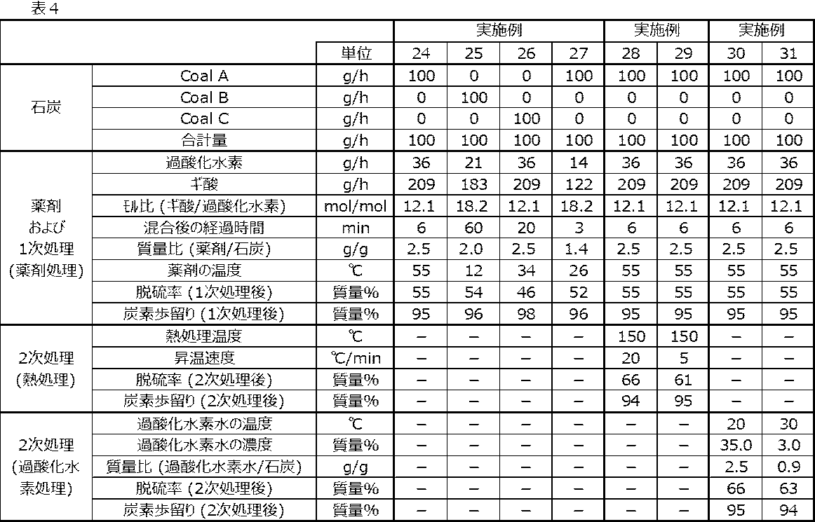
- the test conditions such as the supply amount (flow rate) of coal are shown in Tables 2 to 4 below.
- Examples 1 to 8, 20 to 22 and 24 to 27, and Comparative Examples 1 to 2 only the above-mentioned primary treatment (chemical treatment) was performed. That is, the coal after contact with the chemical was taken out, and the desulfurization rate and the carbon yield were determined.
- Examples 9 to 13, 23 and 28 to 29, the above-mentioned secondary treatment (heat treatment) was further performed. That is, after the primary treatment (chemical treatment), coal was further introduced into a heat treatment apparatus capable of raising the temperature to 1200 ° C. and heat-treated in a nitrogen atmosphere to determine the desulfurization rate and carbon yield after the heat treatment. ..
- Example 14 to 19 and 30 to 31 the above-mentioned secondary treatment (hydrogen peroxide treatment) was further performed. That is, after the primary treatment (chemical treatment), coal was further introduced into a hydrogen peroxide treatment apparatus and subjected to hydrogen peroxide treatment, and the desulfurization rate and carbon yield after the hydrogen peroxide treatment were determined.
- an aqueous solution having a hydrogen peroxide concentration of 35% by mass was used as the hydrogen peroxide.
- acetic acid acetic acid having a purity of 99% by mass was used.
- peracetic acid an aqueous solution having a peracetic acid concentration of 30% by mass was used.
- formic acid formic acid having a purity of 99% by mass was used.
- Example 1 has a molar ratio (acetic acid / hydrogen peroxide) of 12.1 and Example 1 has a molar ratio (acetic acid / hydrogen peroxide) of 0.8.
- the desulfurization rate was higher than that, and the desulfurization effect was more excellent.
- Example 1 Comparing Example 1 and Example 6, the desulfurization rate of Example 1 in which the elapsed time after mixing acetic acid and hydrogen peroxide is 60 minutes is higher than that in Example 6 in which this time is 20 minutes. , The desulfurization effect was better.
- Example 7 Comparing Example 1 and Example 7, the desulfurization rate of Example 1 having a mass ratio (drug / coal) of 2.5 is higher than that of Example 7 having a mass ratio (drug / coal) of 0.9. Was high, and the desulfurization effect was better.
- Example 1 in which the temperature of the chemicals in contact with coal is 56 ° C. has a higher desulfurization rate than Example 8 in which this temperature is 9 ° C., and has a desulfurization effect. was better.
- the desulfurization rates of Examples 9 to 13 were equal to or higher than the desulfurization rates of Examples 1 to 8 (after the primary treatment). Comparing Example 9 and Example 12, the desulfurization rate (after the secondary treatment) of Example 9 having a heat treatment temperature of 150 ° C. is higher than that of Example 12 having a heat treatment temperature of 135 ° C., and the desulfurization effect is higher. It was better. Comparing Example 9 and Example 13, Example 9 in which the heating rate when raising the temperature to the heat treatment temperature is 20 ° C./min is higher than that in Example 13 in which the heating rate is 5 ° C./min. The desulfurization rate (after the secondary treatment) was high, and the desulfurization effect was more excellent.
- the desulfurization rates of Examples 14 to 19 were equal to or higher than the desulfurization rates of Examples 1 to 8 (after the primary treatment). Comparing Example 14 and Example 17, the desulfurization rate (after the secondary treatment) of Example 14 in which the temperature of the hydrogen peroxide solution is 20 ° C. is higher than that of Example 17 in which the temperature is 45 ° C. , The desulfurization effect was better. Comparing Example 14 and Example 18, the desulfurization rate (2) of Example 14 having a hydrogen peroxide solution concentration of 35.0% by mass is higher than that of Example 18 having this concentration of 1.5% by mass. After the next treatment), the desulfurization effect was more excellent.
- Example 14 Comparing Example 14 and Example 19, the mass ratio (hydrogen peroxide solution / coal) of Example 14 is 2.5, and the mass ratio (hydrogen peroxide solution / coal) of Example 14 is 0.9.
- the desulfurization rate (after the secondary treatment) was higher than that of Example 19, and the desulfurization effect was more excellent.
- Examples 24 to 31 in which a mixed solution of hydrogen peroxide and formic acid was used as a drug showed a higher desulfurization rate than Comparative Examples 1 and 2 (see Table 2) in which this was not used, and a sufficient desulfurization effect was obtained. I found out. The carbon yield also tended to be good. Comparing Example 24 and Example 27, Example 24, which has an elapsed time of 6 minutes after mixing formic acid and hydrogen peroxide, has a higher desulfurization rate than Example 27, which has a time of 3 minutes. , The desulfurization effect was better.
- the desulfurization rates of Examples 28 to 29 were equal to or higher than the desulfurization rates of Examples 24 to 27 (after the primary treatment). Comparing Example 28 and Example 29, Example 28, in which the rate of temperature rise to the heat treatment temperature is 20 ° C./min, is higher than that of Example 29, in which the rate of temperature rise is 5 ° C./min.
- the desulfurization rate (after the secondary treatment) was high, and the desulfurization effect was more excellent.
- the desulfurization rates of Examples 30 to 31 were equal to or higher than the desulfurization rates of Examples 24 to 27 (after the primary treatment). Comparing Example 30 and Example 31, the mass ratio (hydrogen peroxide solution / coal) of Example 30 is 2.5, and the mass ratio (hydrogen peroxide solution / coal) of Example 30 is 0.9. The desulfurization rate (after the secondary treatment) was higher than that of Example 31, and the desulfurization effect was more excellent.
Landscapes
- Chemical & Material Sciences (AREA)
- Oil, Petroleum & Natural Gas (AREA)
- Organic Chemistry (AREA)
- Engineering & Computer Science (AREA)
- Chemical Kinetics & Catalysis (AREA)
- General Chemical & Material Sciences (AREA)
- Combustion & Propulsion (AREA)
- Environmental & Geological Engineering (AREA)
- Life Sciences & Earth Sciences (AREA)
- General Life Sciences & Earth Sciences (AREA)
- Geochemistry & Mineralogy (AREA)
- Geology (AREA)
- Materials Engineering (AREA)
- Production Of Liquid Hydrocarbon Mixture For Refining Petroleum (AREA)
- Solid Fuels And Fuel-Associated Substances (AREA)
- Coke Industry (AREA)
Abstract
Description
また、石炭を熱源として使用する場合には、排ガス中に硫黄酸化物が混入するため、大気汚染防止の観点から、排ガス中からの硫黄分除去に多大な努力を強いられている。
そこで、本発明は、脱硫効果に優れた低硫黄石炭の製造方法を提供することを目的とする。
[1]石炭を、過酸化水素および酢酸の混合溶液である薬剤と接触させることにより、上記石炭中の硫黄を除去する、低硫黄石炭の製造方法。
[2]上記酢酸と上記過酸化水素とのモル比(酢酸/過酸化水素)が、1.2以上60.0以下である、上記[1]に記載の低硫黄石炭の製造方法。
[3]上記薬剤を上記石炭に接触させる前に、上記酢酸と上記過酸化水素とを混合し、
上記混合の後、30分間以上経過してから、上記薬剤を上記石炭に接触させる、上記[1]または[2]に記載の低硫黄石炭の製造方法。
[4]石炭を、過酢酸水溶液である薬剤と接触させることにより、上記石炭中の硫黄を除去する、低硫黄石炭の製造方法。
[5]上記薬剤中の過酢酸の含有量が、10.0質量%以上25.0質量%以下である、上記[4]に記載の低硫黄石炭の製造方法。
[6]石炭を、過酸化水素およびギ酸の混合溶液である薬剤と接触させることにより、上記石炭中の硫黄を除去する、低硫黄石炭の製造方法。
[7]上記ギ酸と上記過酸化水素とのモル比(ギ酸/過酸化水素)が、1.2以上60.0以下である、上記[6]に記載の低硫黄石炭の製造方法。
[8]上記薬剤を上記石炭に接触させる前に、上記ギ酸と上記過酸化水素とを混合し、上記混合の後、5分間以上経過してから、上記薬剤を上記石炭に接触させる、上記[6]または[7]に記載の低硫黄石炭の製造方法。
[9]上記薬剤と上記石炭との質量比(薬剤/石炭)が、1.0以上である、上記[1]~[8]のいずれかに記載の低硫黄石炭の製造方法。
[10]上記石炭と接触させる際の上記薬剤の温度が、10℃以上である、上記[1]~[9]のいずれかに記載の低硫黄石炭の製造方法。
[11]上記石炭と接触させる際の上記薬剤の温度が、60℃以下である、上記[1]~[10]のいずれかに記載の低硫黄石炭の製造方法。
[12]上記石炭が、亜瀝青炭を含む、上記[1]~[11]のいずれかに記載の低硫黄石炭の製造方法。
[13]上記薬剤と接触させた上記石炭を、150℃以上の熱処理温度で熱処理する、上記[1]~[12]のいずれかに記載の低硫黄石炭の製造方法。
[14]上記薬剤と接触させた上記石炭を上記熱処理温度まで昇温させる際の昇温速度が、10℃/min以上である、上記[13]に記載の低硫黄石炭の製造方法。
[15]上記薬剤と接触させた上記石炭を、40℃以下の過酸化水素水と接触させる、上記[1]~[12]のいずれかに記載の低硫黄石炭の製造方法。
[16]上記過酸化水素水の濃度が、2.0質量%以上であり、上記過酸化水素水と上記石炭との質量比(過酸化水素水/石炭)が、1.0以上である、上記[15]に記載の低硫黄石炭の製造方法。
本発明の低硫黄石炭の製造方法(以下、単に「本発明の方法」ともいう)は、石炭を、過酸化水素および酢酸の混合溶液である薬剤と接触させることにより、上記石炭中の硫黄を除去する、低硫黄石炭の製造方法である。
また、本発明の方法は、石炭を、過酢酸水溶液である薬剤と接触させることにより、上記石炭中の硫黄を除去する、低硫黄石炭の製造方法である。
また、本発明の方法は、石炭を、過酸化水素およびギ酸の混合溶液である薬剤と接触させることにより、上記石炭中の硫黄を除去する、低硫黄石炭の製造方法である。
以下では、まず、石炭を特定の薬剤と接触させる1次処理(薬剤処理)を説明する。
無機硫黄としては、FeS2が代表的に挙げられる。有機硫黄としては、ジベンゾチオフェンなどの芳香環の内部に硫黄が存在する芳香族硫黄化合物;メルカプタンなどの脂肪族硫黄化合物;等が挙げられる。このうち、石炭を構成する芳香環の内部に存在する硫黄は、特に除去しにくいことが知られている。
H2O2+CH3COOH⇔CH3COO2H+H2O…(I)
上記式(I)においては、温度や薬剤の混合比率などの各条件に応じて、平衡状態が変化する。このため、各条件の組み合わせにより、各成分の濃度が変動する。好適な条件について、詳細は後述する。
薬剤を石炭と接触させることにより、除去が容易な無機硫黄は溶解して、例えば硫酸イオン等の形態で薬剤中に浸出する。同様に、一部の有機硫黄も酸化されて、硫酸イオン等の形態で薬剤中に浸出する。こうして、石炭は脱硫されて(すなわち、石炭中の硫黄が除去されて)、低硫黄化した石炭(低硫黄石炭)が得られる。
そこで、本発明においては、過酸化水素とギ酸との混合溶液(以下、単に「混合溶液」ともいう)を、薬剤として使用する。混合溶液は、下記式(II)で表される反応により、過酸化水素(H2O2)とギ酸(HCOOH)との反応生成物である過ギ酸(HCOO2H)を生成させる。このような混合溶液を石炭と接触させる。
H2O2+HCOOH⇔HCOO2H+H2O…(II)
薬剤として酢酸と過酸化水素との混合溶液を使用する場合、薬剤における酢酸と過酸化水素とのモル比(酢酸/過酸化水素)は、反応生成物である過酢酸が適量となり脱硫効果がより優れるという理由から、1.2以上が好ましく、5.0以上がより好ましい。
さらに、モル比(酢酸/過酸化水素)がこの範囲であれば、過酸化水素に対して酢酸が過剰となり、混合溶液中に過酸化水素が残留することを抑制できる(後述するように、過酸化水素は、石炭の炭素歩留りを低下させる)。
まず、薬剤中の各成分(酢酸または過酸化水素)のモル量[mol]は、下記式(a)で表される。したがって、薬剤における酢酸と過酸化水素とのモル比(酢酸/過酸化水素)は、下記式(b)により算出される。
モル量=(Li×Ci)/(100×Mi)…(a)
モル比=(L1×C1×M2)/(L2×C2×M1)…(b)
Li:i水溶液の量[g/h]
Ci:i水溶液の濃度[質量%]
Mi:iの分子量[g/mol]
ここで、iは、1のとき酢酸を、2のとき過酸化水素を表す。
酢酸の分子量は60、過酸化水素の分子量は34を用いる。所望のモル比(酢酸/過酸化水素)となるように、水溶液の量Liを調整する。
薬剤としてギ酸と過酸化水素との混合溶液を使用する場合、薬剤におけるギ酸と過酸化水素とのモル比(ギ酸/過酸化水素)は、1.2以上が好ましく、5.0以上がより好ましい。一方、60.0以下が好ましく、20.0以下がより好ましい。理由は、薬剤として酢酸と過酸化水素との混合溶液を使用する場合と同様である。
上記式(II)は、上記式(I)と同様に、反応する2つの物質は1モルずつである。このため、過ギ酸の生成に必要な反応物質のモル量(モル比)は同じである。
モル比(ギ酸/過酸化水素)の求め方は、上記式(a)および(b)の説明において、
「酢酸」を「ギ酸」に読み替える。ギ酸の分子量は46を用いる。
上記式(I)の反応(順方向の反応)は、速度が遅い。このため、酢酸と過酸化水素とを混合した直後は、過酢酸の生成が不十分な場合がある。
本発明者らは、反応速度を種々定量し、上記式(I)の反応が定常状態になるまでに30分程度を要することを明らかにした。
そこで、本発明においては、薬剤を石炭に接触させる前に、酢酸と過酸化水素とを混合し、この混合の後、30分間以上経過してから、薬剤を石炭に接触させることが好ましい。これにより、過酢酸が十分に生成するので、石炭中の硫黄を除去する脱硫効果がより優れる。さらに、過酢酸水素が低減するので、過酸化水素が石炭と反応して炭素歩留りが低下することを抑制できる。
酢酸と過酸化水素との混合後の経過時間は、45分間以上がより好ましく、60分間以上がさらに好ましい。一方、120分間以下が好ましく、80分間以下がより好ましい。
上記式(II)の反応(順方向の反応)は、上記式(I)の反応よりも速度が速い。このため、混合後に、石炭と接触させる前に経過させる時間は、酢酸と過酸化水素とを混合する場合よりも短時間でよい。
具体的には、ギ酸と過酸化水素との混合後の経過時間は、5分間以上が好ましく、6分間以上がより好ましい。一方、90分間以下が好ましく、60分間以下がより好ましい。
薬剤として過酢酸水溶液を用いる場合、薬剤(過酢酸水溶液)中の過酢酸の含有量は、脱硫効果がより優れるという理由から、1.0質量%以上が好ましく、5.0質量%以上が好ましく、10.0質量%以上がさらに好ましい。
一方、薬剤(過酢酸水溶液)中の過酢酸の含有量は、25.0質量%以下が好ましい。過酢酸は高濃度側では発火の危険性などがあるが、この範囲であれば、安全に十分に脱硫できる。
本発明者らは、薬剤と石炭との質量比(薬剤/石炭)について検討した。この検討においては、酢酸と過酸化水素とのモル比(酢酸/過酸化水素)が12.0である薬剤を用いた。
図1は、薬剤と石炭との質量比(薬剤/石炭)に対する脱硫率を示すグラフである。図1のグラフに示すように、石炭の量に対して薬剤の量が多くなると、脱硫率が高くなり、脱硫効果がより優れる。このため、質量比(薬剤/石炭)は、0.5以上が好ましく、1.0以上がより好ましい。
脱硫率[質量%]=100×{1-(W2×%S2)/(W1×%S1)}…(1)
本発明者らは、石炭と接触させる際の薬剤の温度(以下、単に「薬剤の温度」ともいう)についても検討した。この検討においては、酢酸と過酸化水素とのモル比(酢酸/過酸化水素)が12.0である薬剤を用いた。
図2は、薬剤の温度に対する過酢酸の生成量を示すグラフ(下段)、ならびに、薬剤の温度に対する脱硫率(実線)および炭素歩留り(破線)を示すグラフ(上段)である。過酢酸の生成量は、反応寄与物質(過酸化水素および酢酸)が完全に反応したときの計算値を1.0とした指数である。
炭素歩留り[質量%]=100×(W2×%C2)/(W1×%C1)…(2)
過酸化水素および過酢酸(または過ギ酸)が酸化剤となり、石炭の骨格を破壊する場合があり、その場合、硫黄の除去と同時に、意図しない炭素歩留りの低下が生じると考えられる。本発明者らが検討した結果、過酢酸は、チオフェン態硫黄の硫黄-炭素間の結合の切断を先行して生じさせ、炭素骨格(炭素-炭素結合)の破壊はその後に生じることが分かった。炭素骨格の破壊は、過酢酸(または過ギ酸)では弱く、過酸化水素では強い。特に、高温の過酸化水素では、顕著である。
したがって、石炭に薬剤を接触させる際の条件を適切に制御する(例えば、薬剤の温度が高くなりすぎないようにする、混合溶液における過酸化水素の混合比率を適切に調整する)ことにより、炭素骨格の破壊を最小限に留めつつ、チオフェン態硫黄を効果的に除去できる。
本発明に用いる石炭は、特に限定されず、幅広い種類の石炭を使用できるが、亜瀝青炭などの石炭化度が中程度の石炭を含むことが好ましく、亜瀝青炭を含むことがより好ましく、亜瀝青炭であることがさらに好ましい。
このような石炭を用いた場合、無煙炭などの石炭化度が高い石炭を用いた場合よりも脱硫効果がより優れる傾向を示し、かつ、褐炭などの石炭化度が低い石炭を用いた場合よりも炭素歩留りが優れる傾向を示す。
本発明に用いる石炭の粒径(平均粒径)は、特に限定されない。例えば、石炭の粒径が数ミリ程度であっても、脱硫性能に大きな変化は無い。石炭の粒径がこれ以上である場合は、必要に応じて、軽度の粉砕処理を施してもよい。
次に、1次処理によって脱硫された石炭中に残留する硫黄をさらに除去する処理として、2種類の2次処理を説明する。
除去が難しいチオフェン態硫黄は、過酢酸または過ギ酸を作用させることによって、除去されやすい形態に変化するため、比較的低温(150℃程度)の熱処理によって除去できる。
すなわち、脱硫効果がより優れるという理由から、薬剤と接触させた石炭を、さらに熱処理することが好ましい。熱処理温度は150℃以上が好ましく、250℃以上がより好ましく、350℃以上がさらに好ましい。
石炭を熱処理するプロセスのうち、最高温度になるのは、実質的に、コークスの製造プロセスと考えられる。本発明者らが実験した結果、コークス炉での熱処理温度によっても、充分な脱硫効果が発現していること確認された。
したがって、熱処理温度は、例えば、1300℃以下である。
本発明者らの検討によれば、薬剤と接触させた石炭をさらに脱硫するにあたり、上述した熱処理とは別に、低温の過酸化水素を用いた処理をしてもよいことが分かった。
1次処理(薬剤処理)をしていない石炭に過酸化水素を作用させると、上述したように、炭素骨格が破壊されて炭素歩留りが低下する。しかし、1次処理された石炭中に残留する硫黄分は除去されやすい形態となっており、過酸化水素で容易に追加的に脱硫できる。
すなわち、薬剤と接触させた石炭を、さらに、低温の過酸化水素水と接触させることが好ましい。
下限は特に限定されず、過酸化水素水の温度は、例えば、5℃以上である。
過酸化水素水の濃度が3.0質量%以上であれば、得られる効果は、過酸化水素水の濃度によらず、ほぼ一定となる。このため、上限は特に限定されないが、例えば、過酸化水素水の濃度は、35.0質量%以下が好ましい。
過酸化水素は、高濃度側で分解しやすいため、30~35質量%の水溶液として市販されていることが多い。本発明においては、このような市販品の水溶液を、適宜希釈して使用すればよい。
次に、本発明を具体的な設備を用いて実施する場合の例を、図3に基づいて説明する。
図3に示す製造設備は、過酸化水素を貯蔵する過酸化水素貯蔵タンク1および酢酸を貯蔵する酢酸貯蔵タンク3を有する。
過酸化水素貯蔵タンク1の内部の過酸化水素は、過酸化水素輸送管2を介して、薬剤混合槽5に供給される。酢酸貯蔵タンク3の内部の酢酸は、酢酸輸送管4を介して薬剤混合槽5に供給される。過酸化水素輸送管2および酢酸輸送管4には、それぞれ適切な流量制御装置(図示せず)が設置されており、過酸化水素および酢酸の流量制御が可能である。
薬剤混合槽5には、加熱装置6および混合装置7が設置されている。薬剤混合槽5に供給された過酸化水素および酢酸は、必要に応じて加熱装置6を用いて所定温度に昇温されるとともに、混合装置7を用いて混合される。
薬剤混合槽5での混合により得られた混合溶液である薬剤は、薬剤輸送管8を介して、脱硫処理槽9に供給される。薬剤輸送管8には、適切な流量制御装置(図示せず)が設置されており、薬剤の流量制御が可能である。
脱硫処理槽9には、さらに、石炭を貯蔵する石炭貯蔵タンク10から、石炭輸送管11を介して、石炭が供給される。石炭輸送管11には、適切な流量制御装置(図示せず)が設置されており、石炭の流量制御が可能である。
脱硫処理槽9には、加熱装置12が設置されている。加熱装置12は、薬剤混合槽5から供給された薬剤と、石炭貯蔵タンク10から供給された石炭とを、必要に応じて適切な温度に制御する。さらに、脱硫処理槽9には、混合装置13が設置されている。混合装置13は、必要に応じて、薬剤と石炭とをよく混合する。
こうして、脱硫処理槽9においては、石炭は薬剤と接触することにより脱硫されて、低硫黄化した石炭(低硫黄石炭)(以下、「薬剤処理炭」ともいう)が得られる。
ただし、脱硫後の薬剤には硫黄が浸出している場合がある。硫黄が浸出している薬剤を再利用すると、脱硫に悪影響を与える可能性がある。このため、薬剤循環管14には、薬剤排出管15が連結しており、脱硫後の薬剤の一部または全部を、薬剤排出管15を介して排出できる。
薬剤処理炭排出管16aは、脱硫処理槽9において得られた薬剤処理炭を2次処理なしで排出する。熱処理装置連結管16bは、薬剤処理炭を熱処理装置17に輸送する。過酸化水素処理装置連結管16cは、薬剤処理炭を過酸化水素処理装置23に輸送する。
低硫黄石炭(薬剤処理炭)は、熱処理装置17において熱処理を受けると、さらに硫黄が揮発するため、さらに脱硫が進行する。熱処理装置17において熱処理を受けてさらに低硫黄化した石炭(以下、「熱処理炭」ともいう)は、熱処理炭排出管18を介して取り出され、所定の用途で使用される。
さらに、熱処理装置17には、熱処理ガス排出管19が設置されている。熱処理によって生成したガスには、可燃性ガスが含まれる場合がある。その場合、熱処理ガス排出管19を介してガスを取り出して、所定の用途にて使用できる。
過酸化水素処理装置23には、過酸化水素処理装置連結管16cを介して、薬剤処理炭が供給される。過酸化水素処理装置23においては、薬剤処理炭に対して、上述した2次処理(過酸化水素処理)が施される。
過酸化水素処理装置23には、過酸化水素供給管20を介して、過酸化水素が供給される。過酸化水素供給管20は、過酸化水素貯蔵タンク1に連結している。過酸化水素を希釈する場合には、希釈水タンク21から、希釈水供給管22を通して、水を供給してもよい。過酸化水素処理装置23の専用に、別の過酸化水素貯蔵タンク(図示せず)を設置してもよい。
過酸化水素処理装置23には、冷却装置24が設置されている。冷却装置24によって、過酸化水素処理装置23の内部の温度を、必要に応じて適切な温度に制御する。
さらに、過酸化水素処理装置23には、混合装置25が設置されている。混合装置25は、必要に応じて、過酸化水素水と薬剤処理炭とをよく混合する。
1つの排出孔には、過酸化水素循環管27が設置されている。石炭(薬剤処理炭)の脱硫に使用した後の過酸化水素水には、一部、過酸化水素が残留している場合がある。その場合には、過酸化水素水を過酸化水素処理装置23から過酸化水素貯蔵タンク1に還流させて、再利用してもよい。還流先は、別途設置した過酸化水素貯蔵タンク(図示せず)でもよいし、薬剤混合槽5でもよい。
ただし、脱硫後の過酸化水素水には硫黄が浸出している場合がある。硫黄が浸出している過酸化水素水を再利用すると、脱硫に悪影響を与える可能性がある。このため、過酸化水素循環管27には、過酸化水素排出管28が連結しており、脱硫後の過酸化水素水の一部または全部を、過酸化水素排出管28を介して排出できる。
この場合、図3に示す製造設備は、「酢酸貯蔵タンク3」に代えて「ギ酸貯蔵タンク3」を、「酢酸輸送管3」に代えて「ギ酸輸送管3」を有する。
この場合、過酢酸貯蔵タンク1は、過酢酸を貯蔵する。希釈水貯蔵タンク3は、過酢酸を希釈するための希釈水を貯蔵する。過酢酸貯蔵タンク1の内部の過酢酸は、過酢酸輸送管2を介して、薬剤混合槽5に供給される。希釈水貯蔵タンク3の内部の希釈水は、希釈水輸送管4を介して、薬剤混合槽5に供給される。過酢酸輸送管2および希釈水輸送管4には、それぞれ適切な流量制御装置(図示せず)が設置されており、過酢酸および希釈水の流量制御が可能である。
薬剤混合槽5において、供給された過酢酸および希釈水が混合されて、過酢酸水溶液が調製される。
これら以外の点は、上記と同様であるため、説明を省略する。
図3に基づいて説明した製造設備を用いて、本発明の方法により石炭を脱硫して低硫黄石炭を製造する試験を行なった。
石炭として、Coal A(亜瀝青炭)、Coal B(亜瀝青炭)およびCoal C(半無煙炭)からなる群から選ばれる少なくとも1種を用いた。用いた石炭の詳細を下記表1に示す。石炭の粒度は、いずれも平均粒径で300μm程度であった。いずれの石炭も、過酢酸の浸透力は強く、脱硫性能は粒度によって大きな変化は無かった。
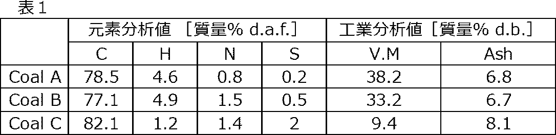
「d.b.」は、無水ベース(dry basis)の分析値であることを意味する。
「V.M」は、工業分析における揮発分(Volatile Matter)の含有量を意味する。
「Ash」は、工業分析における灰分の含有量を意味する。
実施例1~8、20~22および24~27ならびに比較例1~2では、上述した1次処理(薬剤処理)のみを行なった。すなわち、薬剤に接触させた後の石炭を取り出して、脱硫率および炭素歩留りを求めた。
実施例9~13、23および28~29では、さらに、上述した2次処理(熱処理)を行なった。すなわち、1次処理(薬剤処理)の後、さらに、石炭を、1200℃まで昇温可能な熱処理装置に導入して、窒素雰囲気下で熱処理を施し、熱処理後の脱硫率および炭素歩留りを求めた。
実施例14~19および30~31では、さらに、上述した2次処理(過酸化水素処理)を行なった。すなわち、1次処理(薬剤処理)の後、さらに、石炭を、過酸化水素処理装置に導入して、過酸化水素処理を施し、過酸化水素処理後の脱硫率および炭素歩留りを求めた。
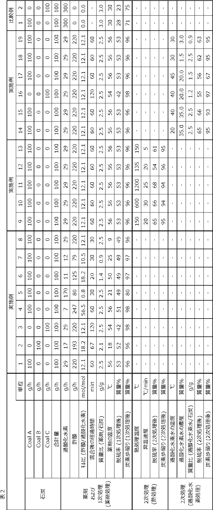

過酸化水素および酢酸の混合溶液を薬剤として用いた実施例1~19は、これを用いなかった比較例1~2よりも高い脱硫率を示し、充分な脱硫効果が得られたことが分かった。炭素歩留りも良好な傾向が見られた。
実施例9と実施例12とを対比すると、熱処理温度が150℃である実施例9は、熱処理温度が135℃である実施例12よりも脱硫率(2次処理後)が高く、脱硫効果がより優れていた。
実施例9と実施例13とを対比すると、熱処理温度まで昇温させる際の昇温速度が20℃/minである実施例9は、この昇温速度が5℃/minである実施例13よりも脱硫率(2次処理後)が高く、脱硫効果がより優れていた。
実施例14と実施例17とを対比すると、過酸化水素水の温度が20℃である実施例14は、この温度が45℃である実施例17よりも脱硫率(2次処理後)が高く、脱硫効果がより優れていた。
実施例14と実施例18とを対比すると、過酸化水素水の濃度が35.0質量%である実施例14は、この濃度が1.5質量%である実施例18よりも脱硫率(2次処理後)が高く、脱硫効果がより優れていた。
実施例14と実施例19とを対比すると、質量比(過酸化水素水/石炭)が2.5である実施例14は、質量比(過酸化水素水/石炭)が0.9である実施例19よりも脱硫率(2次処理後)が高く、脱硫効果がより優れていた。
過酢酸水溶液を薬剤として用いた実施例20~23は、これを用いなかった比較例1~2(表2参照)よりも高い脱硫率を示し、充分な脱硫効果が得られたことが分かった。炭素歩留りも良好な傾向が見られた。
実施例20と実施例22とを対比すると、薬剤(過酢酸水溶液)中の過酢酸の含有量が12.7質量%である実施例20は、この含有量が7.8質量%である実施例22よりも脱硫率が高く、脱硫効果がより優れていた。
実施例23の脱硫率(2次処理後)は、実施例20~22の脱硫率(1次処理後)と同等またはそれ以上であった。
過酸化水素およびギ酸の混合溶液を薬剤として用いた実施例24~31は、これを用いなかった比較例1~2(表2参照)よりも高い脱硫率を示し、充分な脱硫効果が得られたことが分かった。炭素歩留りも良好な傾向が見られた。
実施例24と実施例27とを対比すると、ギ酸と過酸化水素との混合後の経過時間が6分間である実施例24は、この時間が3分間である実施例27よりも脱硫率が高く、脱硫効果がより優れていた。
実施例28と実施例29とを対比すると、熱処理温度まで昇温させる際の昇温速度が20℃/minである実施例28は、この昇温速度が5℃/minである実施例29よりも脱硫率(2次処理後)が高く、脱硫効果がより優れていた。
実施例30と実施例31とを対比すると、質量比(過酸化水素水/石炭)が2.5である実施例30は、質量比(過酸化水素水/石炭)が0.9である実施例31よりも脱硫率(2次処理後)が高く、脱硫効果がより優れていた。
2:過酸化水素輸送管(過酢酸輸送管)
3:酢酸貯蔵タンク(ギ酸貯蔵タンク、希釈水貯蔵タンク)
4:酢酸輸送管(ギ酸輸送管、希釈水輸送管)
5:薬剤混合槽
6:加熱装置
7:混合装置
8:薬剤輸送管
9:脱硫処理槽
10:石炭貯蔵タンク
11:石炭輸送管
12:加熱装置
13:混合装置
14:薬剤循環管
15:薬剤排出管
16:薬剤処理炭輸送管
16a:薬剤処理炭排出管
16b:熱処理装置連結管
16c:過酸化水素処理装置連結管
17:熱処理装置
18:熱処理炭排出管
19:熱処理ガス排出管
20:過酸化水素供給管
21:希釈水タンク
22:希釈水供給管
23:過酸化水素処理装置
24:冷却装置
25:混合装置
26:排出管
27:過酸化水素循環管
28:過酸化水素排出管
Claims (16)
- 石炭を、過酸化水素および酢酸の混合溶液である薬剤と接触させることにより、前記石炭中の硫黄を除去する、低硫黄石炭の製造方法。
- 前記酢酸と前記過酸化水素とのモル比(酢酸/過酸化水素)が、1.2以上60.0以下である、請求項1に記載の低硫黄石炭の製造方法。
- 前記薬剤を前記石炭に接触させる前に、前記酢酸と前記過酸化水素とを混合し、
前記混合の後、30分間以上経過してから、前記薬剤を前記石炭に接触させる、請求項1または2に記載の低硫黄石炭の製造方法。 - 石炭を、過酢酸水溶液である薬剤と接触させることにより、前記石炭中の硫黄を除去する、低硫黄石炭の製造方法。
- 前記薬剤中の過酢酸の含有量が、10.0質量%以上25.0質量%以下である、請求項4に記載の低硫黄石炭の製造方法。
- 石炭を、過酸化水素およびギ酸の混合溶液である薬剤と接触させることにより、前記石炭中の硫黄を除去する、低硫黄石炭の製造方法。
- 前記ギ酸と前記過酸化水素とのモル比(ギ酸/過酸化水素)が、1.2以上60.0以下である、請求項6に記載の低硫黄石炭の製造方法。
- 前記薬剤を前記石炭に接触させる前に、前記ギ酸と前記過酸化水素とを混合し、
前記混合の後、5分間以上経過してから、前記薬剤を前記石炭に接触させる、請求項6または7に記載の低硫黄石炭の製造方法。 - 前記薬剤と前記石炭との質量比(薬剤/石炭)が、1.0以上である、請求項1~8のいずれか1項に記載の低硫黄石炭の製造方法。
- 前記石炭と接触させる際の前記薬剤の温度が、10℃以上である、請求項1~9のいずれか1項に記載の低硫黄石炭の製造方法。
- 前記石炭と接触させる際の前記薬剤の温度が、60℃以下である、請求項1~10のいずれか1項に記載の低硫黄石炭の製造方法。
- 前記石炭が、亜瀝青炭を含む、請求項1~11のいずれか1項に記載の低硫黄石炭の製造方法。
- 前記薬剤と接触させた前記石炭を、150℃以上の熱処理温度で熱処理する、請求項1~12のいずれか1項に記載の低硫黄石炭の製造方法。
- 前記薬剤と接触させた前記石炭を前記熱処理温度まで昇温させる際の昇温速度が、10℃/min以上である、請求項13に記載の低硫黄石炭の製造方法。
- 前記薬剤と接触させた前記石炭を、40℃以下の過酸化水素水と接触させる、請求項1~12のいずれか1項に記載の低硫黄石炭の製造方法。
- 前記過酸化水素水の濃度が、2.0質量%以上であり、
前記過酸化水素水と前記石炭との質量比(過酸化水素水/石炭)が、1.0以上である、請求項15に記載の低硫黄石炭の製造方法。
Priority Applications (5)
| Application Number | Priority Date | Filing Date | Title |
|---|---|---|---|
| CN202080030641.5A CN113748186A (zh) | 2019-04-24 | 2020-04-20 | 低硫煤的制造方法 |
| JP2020545755A JP6992905B2 (ja) | 2019-04-24 | 2020-04-20 | 低硫黄石炭の製造方法 |
| US17/605,626 US20220204880A1 (en) | 2019-04-24 | 2020-04-20 | Method for producing low-sulfur coal |
| CA3134547A CA3134547C (en) | 2019-04-24 | 2020-04-20 | Method for producing low-sulfur coal |
| AU2020261846A AU2020261846B2 (en) | 2019-04-24 | 2020-04-20 | Method for producing low-sulfur coal |
Applications Claiming Priority (4)
| Application Number | Priority Date | Filing Date | Title |
|---|---|---|---|
| JP2019083176 | 2019-04-24 | ||
| JP2019082733 | 2019-04-24 | ||
| JP2019-083176 | 2019-04-24 | ||
| JP2019-082733 | 2019-04-24 |
Publications (1)
| Publication Number | Publication Date |
|---|---|
| WO2020218243A1 true WO2020218243A1 (ja) | 2020-10-29 |
Family
ID=72942739
Family Applications (1)
| Application Number | Title | Priority Date | Filing Date |
|---|---|---|---|
| PCT/JP2020/017060 Ceased WO2020218243A1 (ja) | 2019-04-24 | 2020-04-20 | 低硫黄石炭の製造方法 |
Country Status (6)
| Country | Link |
|---|---|
| US (1) | US20220204880A1 (ja) |
| JP (1) | JP6992905B2 (ja) |
| CN (1) | CN113748186A (ja) |
| AU (1) | AU2020261846B2 (ja) |
| CA (1) | CA3134547C (ja) |
| WO (1) | WO2020218243A1 (ja) |
Citations (4)
| Publication number | Priority date | Publication date | Assignee | Title |
|---|---|---|---|---|
| JPS5373201A (en) * | 1976-12-13 | 1978-06-29 | Atlantic Richfield Co | Method of decreasing sulfure content of coal |
| US4701183A (en) * | 1985-09-16 | 1987-10-20 | Riley John T | Process for removing sulfur from coal |
| JP2002516380A (ja) * | 1998-05-27 | 2002-06-04 | ディーエス2・テック・インコーポレーテッド | 脱硫法 |
| WO2011000914A1 (en) * | 2009-07-01 | 2011-01-06 | Carbosulcis S.P.A. | Process for the desulphurization of low-medium rank coal |
Family Cites Families (13)
| Publication number | Priority date | Publication date | Assignee | Title |
|---|---|---|---|---|
| US4084938A (en) * | 1972-12-20 | 1978-04-18 | Caw Industries, Inc. | Process for treating solid carbonaceous fossil fuels and the products thus prepared |
| US4105416A (en) * | 1977-04-12 | 1978-08-08 | Atlantic Richfield Company | Process for removing sulfur from coal |
| US4377599A (en) * | 1978-04-14 | 1983-03-22 | Caw Industries, Inc. | Processes for employing treated solid carbonaceous fossil fuels |
| US4497636A (en) * | 1983-08-11 | 1985-02-05 | The United States Of America As Represented By The United States Department Of Energy | Process for removing sulfur from coal |
| US4787918A (en) * | 1986-10-31 | 1988-11-29 | The Babcock & Wilcox Company | Process for producing deep cleaned coal |
| ES2131679T3 (es) * | 1994-03-09 | 1999-08-01 | Kemira Chemicals Bv | Procedimiento para la preparacion de soluciones acuosas que contienen acido performico, asi como su utilizacion. |
| US6402940B1 (en) * | 2000-09-01 | 2002-06-11 | Unipure Corporation | Process for removing low amounts of organic sulfur from hydrocarbon fuels |
| US20070151901A1 (en) * | 2005-07-20 | 2007-07-05 | Council Of Scientific And Industrial Research | Process for desulphurisation of liquid hydrocarbon fuels |
| WO2013035200A1 (ja) * | 2011-09-09 | 2013-03-14 | Aida Tetsuo | 超低硫黄燃料油の製造方法 |
| US20150252272A1 (en) * | 2012-09-28 | 2015-09-10 | Aditya Birla Science And Technology Company Limited | Methods and compositions for desulfurization of compositions |
| CN106433851A (zh) * | 2016-10-21 | 2017-02-22 | 太原理工大学 | 微波联合过氧乙酸助剂对高硫煤的脱硫方法 |
| CN109054922A (zh) * | 2018-09-03 | 2018-12-21 | 辽宁工程技术大学 | 一种煤粉裂解净化剂 |
| WO2020117810A1 (en) * | 2018-12-05 | 2020-06-11 | Controlamatics Corporation | A process for producing clean coal using chemical pre-treatment and high shear reactor |
-
2020
- 2020-04-20 CN CN202080030641.5A patent/CN113748186A/zh active Pending
- 2020-04-20 WO PCT/JP2020/017060 patent/WO2020218243A1/ja not_active Ceased
- 2020-04-20 AU AU2020261846A patent/AU2020261846B2/en active Active
- 2020-04-20 CA CA3134547A patent/CA3134547C/en active Active
- 2020-04-20 JP JP2020545755A patent/JP6992905B2/ja active Active
- 2020-04-20 US US17/605,626 patent/US20220204880A1/en not_active Abandoned
Patent Citations (4)
| Publication number | Priority date | Publication date | Assignee | Title |
|---|---|---|---|---|
| JPS5373201A (en) * | 1976-12-13 | 1978-06-29 | Atlantic Richfield Co | Method of decreasing sulfure content of coal |
| US4701183A (en) * | 1985-09-16 | 1987-10-20 | Riley John T | Process for removing sulfur from coal |
| JP2002516380A (ja) * | 1998-05-27 | 2002-06-04 | ディーエス2・テック・インコーポレーテッド | 脱硫法 |
| WO2011000914A1 (en) * | 2009-07-01 | 2011-01-06 | Carbosulcis S.P.A. | Process for the desulphurization of low-medium rank coal |
Also Published As
| Publication number | Publication date |
|---|---|
| JP6992905B2 (ja) | 2022-01-13 |
| JPWO2020218243A1 (ja) | 2021-05-06 |
| AU2020261846A1 (en) | 2021-11-18 |
| CA3134547A1 (en) | 2020-10-29 |
| US20220204880A1 (en) | 2022-06-30 |
| AU2020261846B2 (en) | 2022-11-24 |
| CN113748186A (zh) | 2021-12-03 |
| CA3134547C (en) | 2024-05-28 |
Similar Documents
| Publication | Publication Date | Title |
|---|---|---|
| CN105960376B (zh) | 将二硫化物生物转化成单质硫的方法 | |
| JP6795132B1 (ja) | 低硫黄石炭の製造方法 | |
| JP6992905B2 (ja) | 低硫黄石炭の製造方法 | |
| JPH05311183A (ja) | 石炭の化学的脱硫方法 | |
| RU2780625C1 (ru) | Способ приготовления угля с низким содержанием серы | |
| RU2790043C1 (ru) | Способ приготовления угля с низким содержанием серы | |
| EP0046811B2 (en) | Process for recovering co-rich off-gas in metal smelting | |
| KR101680309B1 (ko) | 황화수소 가스 및 황산화물 가스 제거용 액상철촉매 조성물을 이용한 황 분리 및 회수 시스템 및 그 방법 | |
| JP6065538B2 (ja) | 溶銑の脱銅処理方法 | |
| CN103906558B (zh) | Claus方法中可回收硫的含硫可燃排出物的分级燃烧 | |
| CN108017519B (zh) | 废碱液的层分离方法 | |
| CN108970353B (zh) | 一种催化烟气与含氨酸性气的综合脱硫脱硝方法 | |
| Abdulla et al. | Kinetics of oxidation desulfurization by non-thermal plasma for heavy naphtha | |
| CN116949245A (zh) | 一种氟改性精炼废渣在线高效除硫方法 | |
| RU2812183C1 (ru) | Способ обессеривания нефтяного кокса | |
| CN105130097A (zh) | 一种真空碳酸钾法焦炉煤气脱硫废液的处理方法 | |
| JP2005240123A (ja) | 精製炉の操業方法 | |
| KR20250093050A (ko) | 산업 부생가스를 이용하여 개미산을 생산하는 부생가스 정제 시스템 및 방법 | |
| CN110343558A (zh) | 一种抑制煤高温反应中so2和no释放的方法 | |
| KR20110077627A (ko) | 혐기 소화 여액의 처리방법 | |
| JPH11302667A (ja) | ガス化方法 | |
| KR20090078074A (ko) | 티오시안산염을 함유하는 폐액의 처리방법 | |
| JPH10183225A (ja) | 浸炭機能を有するスクラップの溶解方法および溶解炉 | |
| JP2001247909A (ja) | 溶銑の脱硫方法 | |
| JPS5833452B2 (ja) | コウジヨウハイスイシヨリホウ |
Legal Events
| Date | Code | Title | Description |
|---|---|---|---|
| ENP | Entry into the national phase |
Ref document number: 2020545755 Country of ref document: JP Kind code of ref document: A |
|
| 121 | Ep: the epo has been informed by wipo that ep was designated in this application |
Ref document number: 20795973 Country of ref document: EP Kind code of ref document: A1 |
|
| ENP | Entry into the national phase |
Ref document number: 3134547 Country of ref document: CA |
|
| NENP | Non-entry into the national phase |
Ref country code: DE |
|
| ENP | Entry into the national phase |
Ref document number: 2020261846 Country of ref document: AU Date of ref document: 20200420 Kind code of ref document: A |
|
| 122 | Ep: pct application non-entry in european phase |
Ref document number: 20795973 Country of ref document: EP Kind code of ref document: A1 |