WO2020218110A1 - 刃先交換式ドリル - Google Patents
刃先交換式ドリル Download PDFInfo
- Publication number
- WO2020218110A1 WO2020218110A1 PCT/JP2020/016545 JP2020016545W WO2020218110A1 WO 2020218110 A1 WO2020218110 A1 WO 2020218110A1 JP 2020016545 W JP2020016545 W JP 2020016545W WO 2020218110 A1 WO2020218110 A1 WO 2020218110A1
- Authority
- WO
- WIPO (PCT)
- Prior art keywords
- component
- head component
- body component
- head
- drill
- Prior art date
- Legal status (The legal status is an assumption and is not a legal conclusion. Google has not performed a legal analysis and makes no representation as to the accuracy of the status listed.)
- Ceased
Links
Images








Classifications
-
- B—PERFORMING OPERATIONS; TRANSPORTING
- B23—MACHINE TOOLS; METAL-WORKING NOT OTHERWISE PROVIDED FOR
- B23B—TURNING; BORING
- B23B51/00—Tools for drilling machines
-
- B—PERFORMING OPERATIONS; TRANSPORTING
- B23—MACHINE TOOLS; METAL-WORKING NOT OTHERWISE PROVIDED FOR
- B23B—TURNING; BORING
- B23B51/00—Tools for drilling machines
- B23B51/02—Twist drills
Definitions
- the present invention relates to a drill that is integrated by fastening a head part having a cutting edge and a body part having a shank to each other.
- the cutting edge part and the shank part are formed as separate parts and integrated by fastening each part to each other.
- the so-called replaceable cutting edge drill can replace only the cutting edge parts according to the degree of wear of the cutting edge and the like.
- the head part and the body part are fastened together with the head part fixed to the body part using a fastening part such as a screw (screw fastening type) and the head part and the body without using the fastening part.
- a fastening part such as a screw (screw fastening type)
- screw fastening type screw fastening type
- Patent Document 2 a self-fastening type drill
- a shaft is provided at the end of the head component (cutting head 12 in the drawing) disclosed in Patent Document 1, and the shaft is fitted into a hole in a seat surface provided in the body component. ing. A smooth surface is provided on this shaft, and the head component is fixed by screwing the surface from the outer circumference of the body component.
- the head part when attaching the head part to the body part, there is a possibility that the head part is rotated and fastened to the body part while the head part is in an unstable posture.
- the head parts and body parts have been fastened largely depends on the skill of the operator. If the head part and body part are not completely fastened, the head part may come off the body part during use of the drill.
- the replaceable cutting edge drill of the present invention has a head part having a cutting edge and a body part having a shank as the minimum components.
- the head component includes a bearing surface perpendicular to the axial direction of the head component, a vertical wall surface portion located rearward in the rotational direction of the drill from the flank surface adjacent to the cutting edge, and the drill adjacent to the vertical wall surface portion.
- a curved surface portion located on the rear side and the center side in the rotation direction of is provided.
- the curved surface portion is divided into a front curved surface portion that is inclined toward the tip end side of the head component and a rear curved surface portion that is located at the rear end of the head component with respect to the front curved surface portion.
- each column has an outer peripheral wall surface portion that faces the circumferential direction of the body component and an inner peripheral wall surface portion that faces the central axis of the body component.
- the vertical wall surface portion of the head component and the outer peripheral wall surface portion of the body component are in contact with each other, the rear curved surface portion of the head component and the inner peripheral wall surface portion of the body component are in contact with each other, and the seat surface of the head component and the seat surface of the body component are in contact with each other.
- the surfaces should be in contact with each other.
- the front curved surface portion of the head component and the inner peripheral wall surface portion in each column of the body component are separated from each other, and the head component and the body component are in contact with each other in a state where the rear curved surface portion of the head component and the inner peripheral wall surface portion of the body component are in contact with each other.
- a fastened replaceable cutting edge drill may be used.
- the replaceable cutting edge drill of the present invention stabilizes the head component because the head component and the body component, which are constituent components, are provided with a bearing surface radially centered on a convex portion in the center of the head component and a concave portion in the center of the body component. It can be attached by contacting the seating surface of the body parts in this posture. Therefore, the head component can be accurately installed on the body component without depending on the skill of the operator, and can be easily fastened by rotating the head component.
- FIG. 14 is an enlarged view of the tip of the body component 50 shown in FIG.
- FIG. 15 is an enlarged view of the tip of the body component 50 shown in FIG. It is an upper perspective view of the body component 50. It is a lower perspective view of the body component 50.
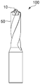
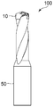
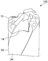
- FIG. 1 A front view of the replaceable cutting edge drill 100 according to an embodiment of the present invention is shown in FIG. 1, a right side view is shown in FIG. 2, and a plan view is shown in FIG. Further, an enlarged front view of the tip of the replaceable cutting edge drill 100 of FIG. 1 is shown in FIG. 4, and an enlarged right side view of the tip of the replaceable cutting edge drill 100 of FIG. 2 is shown on the upper side of the replaceable cutting edge drill 100.
- FIG. 6 shows a perspective view from the tip side
- FIG. 7 shows a perspective view from the lower side (rear end side: shank side) of the cutting edge replaceable drill 100.
- the replaceable cutting edge drill (hereinafter referred to as “drill”) 100 of the present invention is formed by fastening the head component 10 having a cutting edge and the shaft-shaped body component 50 to each other as shown in FIGS. 1 to 3.
- This is a so-called self-fastening drill. That is, the drill 100 is fastened by fitting each form of the head component 10 and the body component 50 to each other as shown in FIGS. 4 to 7 without using a component such as a screw.
- the structures of the head parts and body parts constituting the drill will be described.
- FIG. 8 is a front view of the head component 10 constituting the drill 100 according to the embodiment of the present invention
- 9 is a right side view
- 10 is a plan view
- 11 is a bottom view.
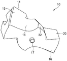
- FIG. 12 shows a perspective view of the head component 10 from the front end side
- FIG. 13 shows a perspective view of the head component 10 from the rear end side.
- the head component 10 that forms a part of the drill of the present invention and substantially carries out the cutting process has two cutting edges 11 and 11 as shown in FIGS. 10 and 12, and is a body component described later. It is attached to one end (opposite the shank) in a removable form.
- flank surfaces 12 and 12 and rake surfaces 13 and 13 connected to the cutting edges 11 and 11 are continuously formed. ing. Thinning surfaces 15 and 15 and grooves 14 and 14 connected to the thinning surfaces 15 and 15 are formed on the counter-rotation direction side of each of the cutting edges 11 and 11 (opposite direction of the arrow shown in FIG. 10: clockwise) as shown in FIGS. 10 and 12. ing.
- the head component 10 is formed with a curved surface portion 30 and a vertical wall surface portion 20 as shown in FIGS. 9, 10 and 12.
- the curved surface portion 30 is a curved surface adjacent to both surfaces of the thinning surface 15 and the groove 14, and the vertical wall surface portion 20 is a surface on the rotation direction side (direction of the arrow shown in FIG. 10: counterclockwise) with respect to the curved surface portion 30. ..
- these curved surface portions 30 and vertical wall surface portions 20 are portions that come into contact with a part of the body component 50 when the head component 10 is fastened to the body component 50 described later.
- the curved surface portion 30 is formed of a front curved surface portion 31 and a rear curved surface portion 32, and is arranged adjacent to each other.
- the front curved surface portion 31 is located closer to the tip end side (drill advancing side) of the head component 10 than the rear curved surface portion 32, and has a shape inclined toward the tip end side of the drill.
- the rear curved surface portion 32 is located on the rear end side (drill shank side) of the head component 10 with respect to the front curved surface portion 31, and is a curved surface adjacent to the seat surface 16 as shown in FIGS. As shown in FIG. 12, they are formed parallel to the direction of the drill axis (central axis O1 of the head component 10 shown in FIGS. 8 and 9). Further, the rear curved surface portion 32 plays a role of tightly fastening the head component 10 and the body component by coming into contact with the surface of the column of the body component described later.
- the vertical wall surface portion 20 is a surface formed parallel to the central axis O1 of the head component 10, and is formed on the side opposite to the rotation direction of the cutting edge 11. As shown in FIGS. 5 and 6, it plays a role of receiving the torque generated by the rotation of the drill (transmitting the rotating force to the head component 10) by coming into contact with the surface of the column constituting the body component described later. ..
- a convex portion 17 is formed at one end of the head component 10, and when the convex portion 17 is fastened to the body component described later, the convex portion 17 is located at the center of the seat surface of the body component. It fits into the provided recess.
- a seat surface 16 is integrally formed in the radial direction and the circumferential direction of the head component 10 so as to surround the convex portion 17 so as to be perpendicular to the axial direction of the head component 10. There is. The seat surface 16 of the head component 10 comes into contact with the seat surface of the body component when it is fastened to the body component.
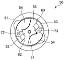
- FIG. 14 A front view of the body component 50 constituting the drill 100 is shown in FIG. 14, a right side view is shown in FIG. 15, and a plan view is shown in FIG. 14 is an enlarged view of the tip of the body component 50, FIG. 15 is an enlarged view of the tip of the body component 50 shown in FIG. 15, and FIG. 19 is a perspective view of the body component 50 from the tip side.
- FIG. 19 A perspective view from the rear end side of the 50 is shown in FIG.
- one end of the body component 50 is a shank 51 attached to a machine tool, and the other end (opposite side of the shank 51) is two columns 52 and 53 extending in the axial direction, during cutting. It has a groove 54 for discharging the generated chips.
- the groove 54 is formed so as to be connected to the groove 14 of the head component to form a single groove when the body component and the head component are fastened to each other.
- the two columns 52 and 53 are located on the outermost peripheral side in the radial direction of the body component 50, and are arranged so as to face each other.
- a seating surface 56 perpendicular to the axial direction of the body component 50 is provided between the columns 52 and 53.
- the seat surface 56 is integrally formed around the recess 57 so as to surround the recess 57 in the radial direction and the circumferential direction of the body component 50.
- the seat surface of the head component of the body component 50 comes into contact with the seat surface 56 of the body component 50 when it is fastened to the head component.
- the head component can be rotated (toward the reverse rotation direction of the replaceable cutting edge drill) and fastened to the body component while the head component remains in a stable posture.
- FIGS. 16 and 19 there is a recess 57 in the center of the seat surface 56 of the body component 50. Therefore, when the seat surface of the head component comes into contact with the seat surface 56 of the body component 50 at the time of fastening to the head component, the convex portion of the head component fulfills the function of positioning in the radial direction of the head component, and the concave portion of the body component 50. By easily fitting into the 57, the stable posture of the head component in the body component 50 can be maintained.
- Each column 52, 53 of the body component 50 has two sets (two types) of surfaces that come into contact with each other when fastening to the head component.
- the first set of surfaces is parallel to the central axis O2 of the body component 50, and the outer peripheral wall surface is formed so that each surface faces the circumferential direction of the body component 50.
- the surfaces of the second set are curved inner peripheral wall surface portions 72 and 73 formed so as to face each other toward the central axis O2 of the body component 50.
- An inclined surface along the front curved surface portion of the head component is formed on a part of the inner peripheral wall surface portions 72 and 73 when the head component and the body component are fastened.
- the outer peripheral wall surface portions 62 and 63 of the body component 50 come into contact with the vertical wall surface portions of the head component, and the inner peripheral wall surface portions 72 and 73 of the body component 50 are head components. Contact the rear curved surface.
- the front curved surface portions 31 and 31 of the head component and the inner peripheral wall surface portions 72 and 73 of the body component 50 are separated from each other. That is, in the cutting edge replaceable drill in which the head component and the body component are fastened to each other, a gap is provided between the front curved surface portion of the head component and the inner peripheral wall surface portion of the body component.
- the drill of the present invention may be optionally provided with an oil hole (oil hole) for discharging the lubricant.
- oil hole oil hole
- oil holes 99 and 99 may be provided so that the lubricant is discharged in the direction of the cutting edge when the head component 10 is fastened. Good.
- the front curved surface portion of the head component constituting the present invention changes in inclination at a constant rate when viewed in the axial cross section of the head component 10 as shown in FIGS. 8 and 12 as an embodiment. It shows a linear linear shape.
- a so-called curved shape (a shape that becomes a curved surface in an axial cross-sectional view) in which the inclination of the head component 10 in the axial direction changes in a linear curve, an exponential function, or a parabola may be used. Absent.
- each seating surface of the head component and the body component constituting the present invention is such that the convex portion 17 is centered on the convex portion 17 and the concave portion 57.
- the shape extends from the periphery of the concave portion 57 to the outer peripheral edge of the head component and the body component, but it may be formed at least around the convex portion 17 and the concave portion 57.
Landscapes
- Engineering & Computer Science (AREA)
- Mechanical Engineering (AREA)
- Drilling Tools (AREA)
Priority Applications (1)
| Application Number | Priority Date | Filing Date | Title |
|---|---|---|---|
| JP2021516030A JP7373716B2 (ja) | 2019-04-23 | 2020-04-15 | 刃先交換式ドリル |
Applications Claiming Priority (2)
| Application Number | Priority Date | Filing Date | Title |
|---|---|---|---|
| JP2019082227 | 2019-04-23 | ||
| JP2019-082227 | 2019-04-23 |
Publications (1)
| Publication Number | Publication Date |
|---|---|
| WO2020218110A1 true WO2020218110A1 (ja) | 2020-10-29 |
Family
ID=72941965
Family Applications (1)
| Application Number | Title | Priority Date | Filing Date |
|---|---|---|---|
| PCT/JP2020/016545 Ceased WO2020218110A1 (ja) | 2019-04-23 | 2020-04-15 | 刃先交換式ドリル |
Country Status (2)
| Country | Link |
|---|---|
| JP (1) | JP7373716B2 (https=) |
| WO (1) | WO2020218110A1 (https=) |
Citations (7)
| Publication number | Priority date | Publication date | Assignee | Title |
|---|---|---|---|---|
| WO2008014367A1 (en) * | 2006-07-26 | 2008-01-31 | Allied Machine & Engineering Corp. | Cutting tool with replaceable tip |
| JP2011005629A (ja) * | 2009-06-23 | 2011-01-13 | Sandvik Intellectual Property Ab | 切り屑除去機械加工用の穴あけ工具、穴あけ工具のルーズトップ及び基体 |
| WO2011070652A1 (ja) * | 2009-12-08 | 2011-06-16 | オーエスジー株式会社 | スローアウェイ式回転工具 |
| JP2012520777A (ja) * | 2009-03-19 | 2012-09-10 | エミューゲ ヴェルク リチャード グリンペル ゲーエムベーハー ウント カンパニー ケージー ファブリック ファープレーツィシオンスヴェルクツォイゲ | モジュール式ドリル |
| CN105537654A (zh) * | 2015-12-30 | 2016-05-04 | 株洲钻石切削刀具股份有限公司 | 一种钻削加工刀具 |
| US20180264558A1 (en) * | 2017-03-16 | 2018-09-20 | Kennametal Inc. | Rotary tool |
| JP2019209439A (ja) * | 2018-06-06 | 2019-12-12 | 株式会社タンガロイ | ドリル |
-
2020
- 2020-04-15 JP JP2021516030A patent/JP7373716B2/ja active Active
- 2020-04-15 WO PCT/JP2020/016545 patent/WO2020218110A1/ja not_active Ceased
Patent Citations (7)
| Publication number | Priority date | Publication date | Assignee | Title |
|---|---|---|---|---|
| WO2008014367A1 (en) * | 2006-07-26 | 2008-01-31 | Allied Machine & Engineering Corp. | Cutting tool with replaceable tip |
| JP2012520777A (ja) * | 2009-03-19 | 2012-09-10 | エミューゲ ヴェルク リチャード グリンペル ゲーエムベーハー ウント カンパニー ケージー ファブリック ファープレーツィシオンスヴェルクツォイゲ | モジュール式ドリル |
| JP2011005629A (ja) * | 2009-06-23 | 2011-01-13 | Sandvik Intellectual Property Ab | 切り屑除去機械加工用の穴あけ工具、穴あけ工具のルーズトップ及び基体 |
| WO2011070652A1 (ja) * | 2009-12-08 | 2011-06-16 | オーエスジー株式会社 | スローアウェイ式回転工具 |
| CN105537654A (zh) * | 2015-12-30 | 2016-05-04 | 株洲钻石切削刀具股份有限公司 | 一种钻削加工刀具 |
| US20180264558A1 (en) * | 2017-03-16 | 2018-09-20 | Kennametal Inc. | Rotary tool |
| JP2019209439A (ja) * | 2018-06-06 | 2019-12-12 | 株式会社タンガロイ | ドリル |
Also Published As
| Publication number | Publication date |
|---|---|
| JP7373716B2 (ja) | 2023-11-06 |
| JPWO2020218110A1 (https=) | 2020-10-29 |
Similar Documents
| Publication | Publication Date | Title |
|---|---|---|
| JP4764421B2 (ja) | 取り外し可能な切削ヘッドを有するドリル | |
| US6595729B2 (en) | Drill with countersinker for chip removing machining | |
| JP5279848B2 (ja) | 先端ヘッド交換式回転工具、先端ヘッド、および工具本体 | |
| KR101028263B1 (ko) | 절삭 공구 조립체 및 절삭 헤드 | |
| CN103052460B (zh) | 具有单独的定中心部分和扭矩传递部分的t型槽铣刀 | |
| JP2010517801A (ja) | ロック部材により取り外し可能に装着される自己拘束式切断ヘッドを備える回転切断工具 | |
| JP2005199424A (ja) | 切屑を排除して切削加工するための回転工具 | |
| KR100254909B1 (ko) | 키레스드릴척 | |
| US3940835A (en) | Slotting cutter and cutting insert therefor | |
| KR102763721B1 (ko) | 커팅 에지와 회전식 밀링 공구가 일체로 형성된 밀링 헤드 | |
| US10207337B2 (en) | Front-loaded, side-activated modular drill | |
| CN106825693A (zh) | 模块化钻头 | |
| JPWO2010027055A1 (ja) | サイドカッター | |
| JP6399389B2 (ja) | ヘッド交換式ドリル、およびヘッド交換式ドリル用のヘッド | |
| JP2006043868A (ja) | ドリル用面取り工具 | |
| WO2020218110A1 (ja) | 刃先交換式ドリル | |
| JP2017113865A (ja) | 面取り工具 | |
| JP7274692B2 (ja) | 刃先交換式ドリル | |
| JP2022060671A (ja) | 刃先交換式ドリル | |
| WO2018105035A1 (ja) | 切削工具、インサートホルダ及びインサート | |
| JP4614921B2 (ja) | スローアウェイ式回転工具 | |
| JP5845816B2 (ja) | 先端部交換式切削工具 | |
| JP2000107923A (ja) | スローアウェイ式サイドカッター | |
| JP7505654B1 (ja) | 工具ボディ及び回転切削工具 | |
| JP7818052B2 (ja) | 径方向の挟持が安定なドリル工具 |
Legal Events
| Date | Code | Title | Description |
|---|---|---|---|
| 121 | Ep: the epo has been informed by wipo that ep was designated in this application |
Ref document number: 20795090 Country of ref document: EP Kind code of ref document: A1 |
|
| NENP | Non-entry into the national phase |
Ref country code: DE |
|
| ENP | Entry into the national phase |
Ref document number: 2021516030 Country of ref document: JP Kind code of ref document: A |
|
| 122 | Ep: pct application non-entry in european phase |
Ref document number: 20795090 Country of ref document: EP Kind code of ref document: A1 |