WO2020217353A1 - 加工装置、加工方法及び加工システム - Google Patents
加工装置、加工方法及び加工システム Download PDFInfo
- Publication number
- WO2020217353A1 WO2020217353A1 PCT/JP2019/017483 JP2019017483W WO2020217353A1 WO 2020217353 A1 WO2020217353 A1 WO 2020217353A1 JP 2019017483 W JP2019017483 W JP 2019017483W WO 2020217353 A1 WO2020217353 A1 WO 2020217353A1
- Authority
- WO
- WIPO (PCT)
- Prior art keywords
- light
- processing
- optical system
- coating film
- polarized
- Prior art date
- Legal status (The legal status is an assumption and is not a legal conclusion. Google has not performed a legal analysis and makes no representation as to the accuracy of the status listed.)
- Ceased
Links
Images


Classifications
-
- B—PERFORMING OPERATIONS; TRANSPORTING
- B23—MACHINE TOOLS; METAL-WORKING NOT OTHERWISE PROVIDED FOR
- B23K—SOLDERING OR UNSOLDERING; WELDING; CLADDING OR PLATING BY SOLDERING OR WELDING; CUTTING BY APPLYING HEAT LOCALLY, e.g. FLAME CUTTING; WORKING BY LASER BEAM
- B23K26/00—Working by laser beam, e.g. welding, cutting or boring
- B23K26/02—Positioning or observing the workpiece, e.g. with respect to the point of impact; Aligning, aiming or focusing the laser beam
- B23K26/06—Shaping the laser beam, e.g. by masks or multi-focusing
- B23K26/067—Dividing the beam into multiple beams, e.g. multi-focusing
- B23K26/0676—Dividing the beam into multiple beams, e.g. multi-focusing into dependently operating sub-beams, e.g. an array of spots with fixed spatial relationship or for performing simultaneously identical operations
-
- B—PERFORMING OPERATIONS; TRANSPORTING
- B23—MACHINE TOOLS; METAL-WORKING NOT OTHERWISE PROVIDED FOR
- B23K—SOLDERING OR UNSOLDERING; WELDING; CLADDING OR PLATING BY SOLDERING OR WELDING; CUTTING BY APPLYING HEAT LOCALLY, e.g. FLAME CUTTING; WORKING BY LASER BEAM
- B23K26/00—Working by laser beam, e.g. welding, cutting or boring
- B23K26/352—Working by laser beam, e.g. welding, cutting or boring for surface treatment
- B23K26/359—Working by laser beam, e.g. welding, cutting or boring for surface treatment by providing a line or line pattern, e.g. a dotted break initiation line
-
- B—PERFORMING OPERATIONS; TRANSPORTING
- B23—MACHINE TOOLS; METAL-WORKING NOT OTHERWISE PROVIDED FOR
- B23K—SOLDERING OR UNSOLDERING; WELDING; CLADDING OR PLATING BY SOLDERING OR WELDING; CUTTING BY APPLYING HEAT LOCALLY, e.g. FLAME CUTTING; WORKING BY LASER BEAM
- B23K26/00—Working by laser beam, e.g. welding, cutting or boring
- B23K26/0006—Working by laser beam, e.g. welding, cutting or boring taking account of the properties of the material involved
-
- B—PERFORMING OPERATIONS; TRANSPORTING
- B23—MACHINE TOOLS; METAL-WORKING NOT OTHERWISE PROVIDED FOR
- B23K—SOLDERING OR UNSOLDERING; WELDING; CLADDING OR PLATING BY SOLDERING OR WELDING; CUTTING BY APPLYING HEAT LOCALLY, e.g. FLAME CUTTING; WORKING BY LASER BEAM
- B23K26/00—Working by laser beam, e.g. welding, cutting or boring
- B23K26/02—Positioning or observing the workpiece, e.g. with respect to the point of impact; Aligning, aiming or focusing the laser beam
- B23K26/06—Shaping the laser beam, e.g. by masks or multi-focusing
- B23K26/062—Shaping the laser beam, e.g. by masks or multi-focusing by direct control of the laser beam
- B23K26/0622—Shaping the laser beam, e.g. by masks or multi-focusing by direct control of the laser beam by shaping pulses
- B23K26/0624—Shaping the laser beam, e.g. by masks or multi-focusing by direct control of the laser beam by shaping pulses using ultrashort pulses, i.e. pulses of 1 ns or less
-
- B—PERFORMING OPERATIONS; TRANSPORTING
- B23—MACHINE TOOLS; METAL-WORKING NOT OTHERWISE PROVIDED FOR
- B23K—SOLDERING OR UNSOLDERING; WELDING; CLADDING OR PLATING BY SOLDERING OR WELDING; CUTTING BY APPLYING HEAT LOCALLY, e.g. FLAME CUTTING; WORKING BY LASER BEAM
- B23K26/00—Working by laser beam, e.g. welding, cutting or boring
- B23K26/02—Positioning or observing the workpiece, e.g. with respect to the point of impact; Aligning, aiming or focusing the laser beam
- B23K26/06—Shaping the laser beam, e.g. by masks or multi-focusing
- B23K26/064—Shaping the laser beam, e.g. by masks or multi-focusing by means of optical elements, e.g. lenses, mirrors or prisms
-
- B—PERFORMING OPERATIONS; TRANSPORTING
- B23—MACHINE TOOLS; METAL-WORKING NOT OTHERWISE PROVIDED FOR
- B23K—SOLDERING OR UNSOLDERING; WELDING; CLADDING OR PLATING BY SOLDERING OR WELDING; CUTTING BY APPLYING HEAT LOCALLY, e.g. FLAME CUTTING; WORKING BY LASER BEAM
- B23K26/00—Working by laser beam, e.g. welding, cutting or boring
- B23K26/02—Positioning or observing the workpiece, e.g. with respect to the point of impact; Aligning, aiming or focusing the laser beam
- B23K26/06—Shaping the laser beam, e.g. by masks or multi-focusing
- B23K26/067—Dividing the beam into multiple beams, e.g. multi-focusing
- B23K26/0673—Dividing the beam into multiple beams, e.g. multi-focusing into independently operating sub-beams, e.g. beam multiplexing to provide laser beams for several stations
-
- B—PERFORMING OPERATIONS; TRANSPORTING
- B23—MACHINE TOOLS; METAL-WORKING NOT OTHERWISE PROVIDED FOR
- B23K—SOLDERING OR UNSOLDERING; WELDING; CLADDING OR PLATING BY SOLDERING OR WELDING; CUTTING BY APPLYING HEAT LOCALLY, e.g. FLAME CUTTING; WORKING BY LASER BEAM
- B23K26/00—Working by laser beam, e.g. welding, cutting or boring
- B23K26/08—Devices involving relative movement between laser beam and workpiece
- B23K26/082—Scanning systems, i.e. devices involving movement of the laser beam relative to the laser head
-
- B—PERFORMING OPERATIONS; TRANSPORTING
- B23—MACHINE TOOLS; METAL-WORKING NOT OTHERWISE PROVIDED FOR
- B23K—SOLDERING OR UNSOLDERING; WELDING; CLADDING OR PLATING BY SOLDERING OR WELDING; CUTTING BY APPLYING HEAT LOCALLY, e.g. FLAME CUTTING; WORKING BY LASER BEAM
- B23K26/00—Working by laser beam, e.g. welding, cutting or boring
- B23K26/12—Working by laser beam, e.g. welding, cutting or boring in a special environment or atmosphere, e.g. in an enclosure
- B23K26/123—Working by laser beam, e.g. welding, cutting or boring in a special environment or atmosphere, e.g. in an enclosure in an atmosphere of particular gases
-
- B—PERFORMING OPERATIONS; TRANSPORTING
- B23—MACHINE TOOLS; METAL-WORKING NOT OTHERWISE PROVIDED FOR
- B23K—SOLDERING OR UNSOLDERING; WELDING; CLADDING OR PLATING BY SOLDERING OR WELDING; CUTTING BY APPLYING HEAT LOCALLY, e.g. FLAME CUTTING; WORKING BY LASER BEAM
- B23K26/00—Working by laser beam, e.g. welding, cutting or boring
- B23K26/12—Working by laser beam, e.g. welding, cutting or boring in a special environment or atmosphere, e.g. in an enclosure
- B23K26/127—Working by laser beam, e.g. welding, cutting or boring in a special environment or atmosphere, e.g. in an enclosure in an enclosure
-
- B—PERFORMING OPERATIONS; TRANSPORTING
- B23—MACHINE TOOLS; METAL-WORKING NOT OTHERWISE PROVIDED FOR
- B23K—SOLDERING OR UNSOLDERING; WELDING; CLADDING OR PLATING BY SOLDERING OR WELDING; CUTTING BY APPLYING HEAT LOCALLY, e.g. FLAME CUTTING; WORKING BY LASER BEAM
- B23K26/00—Working by laser beam, e.g. welding, cutting or boring
- B23K26/14—Working by laser beam, e.g. welding, cutting or boring using a fluid stream, e.g. a jet of gas, in conjunction with the laser beam; Nozzles therefor
- B23K26/1462—Nozzles; Features related to nozzles
- B23K26/1464—Supply to, or discharge from, nozzles of media, e.g. gas, powder, wire
- B23K26/1476—Features inside the nozzle for feeding the fluid stream through the nozzle
-
- B—PERFORMING OPERATIONS; TRANSPORTING
- B23—MACHINE TOOLS; METAL-WORKING NOT OTHERWISE PROVIDED FOR
- B23K—SOLDERING OR UNSOLDERING; WELDING; CLADDING OR PLATING BY SOLDERING OR WELDING; CUTTING BY APPLYING HEAT LOCALLY, e.g. FLAME CUTTING; WORKING BY LASER BEAM
- B23K26/00—Working by laser beam, e.g. welding, cutting or boring
- B23K26/16—Removal of by-products, e.g. particles or vapours produced during treatment of a workpiece
-
- B—PERFORMING OPERATIONS; TRANSPORTING
- B23—MACHINE TOOLS; METAL-WORKING NOT OTHERWISE PROVIDED FOR
- B23K—SOLDERING OR UNSOLDERING; WELDING; CLADDING OR PLATING BY SOLDERING OR WELDING; CUTTING BY APPLYING HEAT LOCALLY, e.g. FLAME CUTTING; WORKING BY LASER BEAM
- B23K26/00—Working by laser beam, e.g. welding, cutting or boring
- B23K26/352—Working by laser beam, e.g. welding, cutting or boring for surface treatment
- B23K26/355—Texturing
-
- B—PERFORMING OPERATIONS; TRANSPORTING
- B23—MACHINE TOOLS; METAL-WORKING NOT OTHERWISE PROVIDED FOR
- B23K—SOLDERING OR UNSOLDERING; WELDING; CLADDING OR PLATING BY SOLDERING OR WELDING; CUTTING BY APPLYING HEAT LOCALLY, e.g. FLAME CUTTING; WORKING BY LASER BEAM
- B23K26/00—Working by laser beam, e.g. welding, cutting or boring
- B23K26/36—Removing material
- B23K26/362—Laser etching
-
- B—PERFORMING OPERATIONS; TRANSPORTING
- B23—MACHINE TOOLS; METAL-WORKING NOT OTHERWISE PROVIDED FOR
- B23K—SOLDERING OR UNSOLDERING; WELDING; CLADDING OR PLATING BY SOLDERING OR WELDING; CUTTING BY APPLYING HEAT LOCALLY, e.g. FLAME CUTTING; WORKING BY LASER BEAM
- B23K26/00—Working by laser beam, e.g. welding, cutting or boring
- B23K26/36—Removing material
- B23K26/40—Removing material taking account of the properties of the material involved
- B23K26/402—Removing material taking account of the properties of the material involved involving non-metallic material, e.g. isolators
-
- G—PHYSICS
- G02—OPTICS
- G02B—OPTICAL ELEMENTS, SYSTEMS OR APPARATUS
- G02B26/00—Optical devices or arrangements for the control of light using movable or deformable optical elements
- G02B26/08—Optical devices or arrangements for the control of light using movable or deformable optical elements for controlling the direction of light
- G02B26/10—Scanning systems
- G02B26/101—Scanning systems with both horizontal and vertical deflecting means, e.g. raster or XY scanners
-
- G—PHYSICS
- G02—OPTICS
- G02B—OPTICAL ELEMENTS, SYSTEMS OR APPARATUS
- G02B26/00—Optical devices or arrangements for the control of light using movable or deformable optical elements
- G02B26/08—Optical devices or arrangements for the control of light using movable or deformable optical elements for controlling the direction of light
- G02B26/10—Scanning systems
- G02B26/105—Scanning systems with one or more pivoting mirrors or galvano-mirrors
-
- G—PHYSICS
- G02—OPTICS
- G02B—OPTICAL ELEMENTS, SYSTEMS OR APPARATUS
- G02B27/00—Optical systems or apparatus not provided for by any of the groups G02B1/00 - G02B26/00, G02B30/00
- G02B27/09—Beam shaping, e.g. changing the cross-sectional area, not otherwise provided for
- G02B27/0905—Dividing and/or superposing multiple light beams
-
- G—PHYSICS
- G02—OPTICS
- G02B—OPTICAL ELEMENTS, SYSTEMS OR APPARATUS
- G02B27/00—Optical systems or apparatus not provided for by any of the groups G02B1/00 - G02B26/00, G02B30/00
- G02B27/10—Beam splitting or combining systems
- G02B27/14—Beam splitting or combining systems operating by reflection only
-
- B—PERFORMING OPERATIONS; TRANSPORTING
- B23—MACHINE TOOLS; METAL-WORKING NOT OTHERWISE PROVIDED FOR
- B23K—SOLDERING OR UNSOLDERING; WELDING; CLADDING OR PLATING BY SOLDERING OR WELDING; CUTTING BY APPLYING HEAT LOCALLY, e.g. FLAME CUTTING; WORKING BY LASER BEAM
- B23K2101/00—Articles made by soldering, welding or cutting
- B23K2101/006—Vehicles
-
- B—PERFORMING OPERATIONS; TRANSPORTING
- B23—MACHINE TOOLS; METAL-WORKING NOT OTHERWISE PROVIDED FOR
- B23K—SOLDERING OR UNSOLDERING; WELDING; CLADDING OR PLATING BY SOLDERING OR WELDING; CUTTING BY APPLYING HEAT LOCALLY, e.g. FLAME CUTTING; WORKING BY LASER BEAM
- B23K2101/00—Articles made by soldering, welding or cutting
- B23K2101/34—Coated articles ; Surface treated articles
-
- B—PERFORMING OPERATIONS; TRANSPORTING
- B23—MACHINE TOOLS; METAL-WORKING NOT OTHERWISE PROVIDED FOR
- B23K—SOLDERING OR UNSOLDERING; WELDING; CLADDING OR PLATING BY SOLDERING OR WELDING; CUTTING BY APPLYING HEAT LOCALLY, e.g. FLAME CUTTING; WORKING BY LASER BEAM
- B23K2103/00—Materials to be soldered, welded or cut
- B23K2103/16—Composite materials
- B23K2103/166—Multilayered materials
- B23K2103/172—Multilayered materials wherein at least one of the layers is non-metallic
-
- B—PERFORMING OPERATIONS; TRANSPORTING
- B23—MACHINE TOOLS; METAL-WORKING NOT OTHERWISE PROVIDED FOR
- B23K—SOLDERING OR UNSOLDERING; WELDING; CLADDING OR PLATING BY SOLDERING OR WELDING; CUTTING BY APPLYING HEAT LOCALLY, e.g. FLAME CUTTING; WORKING BY LASER BEAM
- B23K2103/00—Materials to be soldered, welded or cut
- B23K2103/30—Organic materials
- B23K2103/42—Plastics other than composite materials
Definitions
- the present invention relates to a technical field of a processing device, a processing method, and a processing system capable of processing an object by irradiating it with processing light.
- Patent Document 1 describes a processing device that irradiates the surface of an object with a laser beam to form a structure. In this type of processing equipment, it is required to properly form a structure on an object.
- the first processing light is irradiated to form the first irradiation region on the surface and the second processing is performed.
- the surface is provided with a light irradiation device that irradiates light to form a second irradiation region that at least partially overlaps the first irradiation region, and the light irradiation device displays the overlapping state of the first and second irradiation regions.
- a processing apparatus having a changeable member is provided.
- the processing method of irradiating the surface of an object with processing light to process the object irradiating the surface with the first processing light to form a first irradiation region on the surface, and second.
- the processing apparatus for processing the object by irradiating the object with processing light the first optical system for branching the incident light into the first light and the second light, and the first optical system.
- the second optical system that returns the first light from the first optical system to the first optical system as the third light
- the first optical system that uses the second light from the first optical system as the fourth light.
- the first optical system comprises a third optical system that returns the third light from the second optical system and the fourth light from the third optical system to different positions on the surface of the object.
- a processing system that emits a plurality of the processing optics irradiated to the
- the light irradiation device for processing the object by irradiating the object with a plurality of processing lights and the said device on the surface of the object so that a desired pattern structure is formed on the object.
- a processing device including an irradiation position changing device for changing the relative positional relationship of irradiation positions of a plurality of processing lights is provided.
- a processing system that processes an object so as to irradiate the object with processing light to form a pattern structure extending in a desired direction on the object, and is along the surface of the object.
- a first movable device that moves so as to change the relative position between the irradiation position of the processing light and the surface of the object in the first direction, and a first movable device that is along the surface of the object and intersects the first direction. It is movable so as to change the relative position between the irradiation position of the processing light and the surface of the object in two directions, and is provided with a second movable device that is heavier and / or larger than the first movable device.
- the first angle formed by the axis extending in the direction and the axis extending in the first direction is smaller than the second angle formed by the axis extending in the desired direction and the axis extending in the second direction.
- a processing system in which the second movable device is aligned with respect to the surface is provided.
- a processing device for processing the object so as to irradiate the object with processing light to form a pattern structure extending in a desired direction on the surface of the object, and the pattern structure are formed.
- a machining system including a control device for controlling the machining device so as to form the pattern structure based on pattern information regarding the pattern structure generated from a simulation model for simulating the object is provided.
- a light irradiating device for irradiating the surface of an object with processing light and a position changing device for changing a target irradiation position of the processing light on the surface of the object and a relative position with respect to the surface.
- the first operation of scanning the processed light on the surface along the first axis along the surface by using the light irradiation device and the position changing device, and the surface intersecting with the first axis.
- the second operation of changing the relative position of the processing light and the surface is alternately repeated along the second axis along the second axis, and the first operation is directed toward the first direction along the first axis.
- a processing system including a second scanning operation of scanning the processing light on the surface so that the target irradiation position moves relative to the surface in the second direction in the opposite direction. ..
- the first optical system arranged in the optical path of the processing light from the light source and the said.
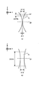
- a beam cross section arranged in the optical path of the processing light from the light source, including a second optical system that concentrates the processing light on the surface, and at a convergence position of the processing light via the first and second optical systems.
- the size of the beam is larger than the size of the beam cross section at the converging position of the processing light via the second optical system.
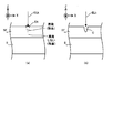
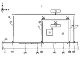
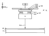
- FIG. 1 is a cross-sectional view schematically showing the overall structure of the processing system of the first embodiment.
- FIG. 2A and FIG. 2B is a cross-sectional view schematically showing a state of processing of a coating film formed on the surface of an object to be processed.
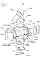
- FIG. 3 is a perspective view schematically showing a light irradiation device included in the processing system of the first embodiment.
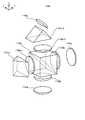
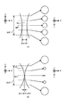
- FIG. 4 is a cross-sectional view showing the structure of the multi-beam optical system.
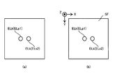
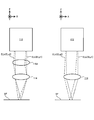
- FIG. 5 (a) is a plan view showing a beam spot formed on a predetermined optical surface by a plurality of processed lights emitted by the multi-beam optical system, and FIG.
- FIG. 5 (b) is a plan view showing the beam spots emitted by the multi-beam optical system. It is a top view which shows the beam spot which a plurality of processing light forms on a coating film.
- FIG. 6A is a cross-sectional view showing a cross section of the riblet structure formed by the processing system of the first embodiment
- FIG. 6B is a perspective view showing the riblet structure formed by the processing system of the present embodiment.
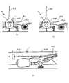
- Is. 7 (a) and 7 (b) are front views showing an aircraft which is an example of a processing object on which a riblet structure is formed
- FIG. 6 (c) is a processing in which a riblet structure is formed. It is a side view which shows the aircraft which is an example of an object.
- FIG. 7 (a) and 7 (b) are front views showing an aircraft which is an example of a processing object on which a riblet structure is formed
- FIG. 6 (c) is a processing in which a riblet structure is formed
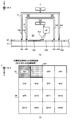
- FIG. 8 is a plan view showing a plurality of processed shot regions set on the surface of the coating film SF.
- FIG. 9 is a cross-sectional view showing a processing apparatus that performs one step of a processing operation for forming a riblet structure.
- FIG. 10 (a) is a cross-sectional view showing a processing apparatus that performs one step of a processing operation for forming a riblet structure, and
- FIG. 10 (b) shows one step of the processing operation shown in FIG. 10 (a). It is a top view which shows the surface of the coating film performed.
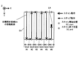
- FIG. 11 is a plan view showing the scanning locus of the processing light (that is, the moving locus of the target irradiation region) during the period in which the scanning operation and the step operation are repeated.
- FIG. 12 is a cross-sectional view showing a processing apparatus that performs one step of a processing operation for forming a riblet structure.
- FIG. 13 (a) is a cross-sectional view showing a processing apparatus that performs one step of the processing operation for forming the riblet structure, and
- FIG. 13 (b) shows one step of the processing operation shown in FIG. 13 (a). It is a top view which shows the surface of the coating film performed.
- FIG. 14 is a cross-sectional view showing a processing apparatus that performs one step of a processing operation for forming a riblet structure.
- FIG. 15 is a cross-sectional view showing a processing apparatus that performs one step of a processing operation for forming a riblet structure.
- FIG. 16 is a cross-sectional view showing a processing apparatus that performs one step of a processing operation for forming a riblet structure.
- FIG. 17 is a cross-sectional view showing a processing apparatus that performs one step of a processing operation for forming a riblet structure.
- FIG. 18 is a cross-sectional view showing a processing apparatus that performs one step of a processing operation for forming a riblet structure.
- FIG. 19 is a cross-sectional view showing a processing apparatus that performs one step of a processing operation for forming a riblet structure.
- FIG. 20 is a cross-sectional view schematically showing another example of the multi-beam optical system.
- FIG. 20 is a cross-sectional view schematically showing another example of the multi-beam optical system.
- FIG. 21 is a cross-sectional view showing a plurality of multi-beam optical systems included in the light irradiation device of the second embodiment.
- FIG. 22 (a) is a cross-sectional view schematically showing how each of the plurality of multi-beam optical systems divides the light source light into a plurality of processed lights, and
- FIG. 22 (b) shows a plurality of multi-beam optical systems. It is a top view which shows the beam spot which a plurality of processing light ELks emitted by each of these are formed on a predetermined optical surface.
- FIG. 23 is a cross-sectional view showing the multi-beam optical system of the third embodiment.
- FIG. 24 (a) is a cross-sectional view showing a multi-beam optical system before the reflection mirror moves
- FIG. 24 (b) shows a plurality of shots emitted from the multi-beam optical system in the state shown in FIG. 24 (a).
- FIG. 24 (c) is a plan view showing a plurality of beam spots formed on the coating film by the processing light of FIG. 24 (c)
- FIG. 24 (c) is a cross-sectional view showing a multi-beam optical system after the reflection mirror has moved.
- FIG. 25 (a) is a plan view showing the positional relationship of the plurality of irradiation regions before the reflection mirror moves
- FIG. 25 (b) shows the plurality of irradiation regions shown in FIG. 25 (a).
- FIG. 25 (c) is a cross-sectional view showing a concave structure formed in the case
- FIG. 25 (c) is a plan view showing a positional relationship of a plurality of irradiation regions after the reflection mirror has moved
- FIG. 25 (d) is a view. It is sectional drawing which shows the concave structure formed when the plurality of irradiation regions shown in 25 (c) are set.
- FIG. 26 (a) is a plan view showing the positional relationship of a plurality of irradiation regions that partially overlap
- FIG. 26 (b) shows a case where the plurality of irradiation regions shown in FIG. 26 (a) are set.
- It is sectional drawing which shows the concave structure formed in. 27 (a) is a plan view showing the positional relationship of the four irradiation regions that do not partially overlap
- FIG. 27 (b) shows the case where a plurality of irradiation regions shown in FIG. 27 (a) are set.
- 27 (c) is a plan view showing the positional relationship of the four partially overlapping irradiation regions
- FIG. 27 (d) is a plan view showing the positional relationship of the four irradiation regions formed in FIG. 27 (d).
- FIG. 27 (e) is a cross-sectional view showing a concave structure formed when a plurality of irradiation regions shown in c) are set, and
- FIG. 27 (e) is a plan view showing the positional relationship of four partially overlapping irradiation regions.
- 27 (f) is a cross-sectional view showing a concave structure formed when a plurality of irradiation regions shown in FIG. 27 (c) are set.
- FIG. 28 is a perspective view showing the light irradiation device of the fourth embodiment.
- FIG. 28 is a perspective view showing the light irradiation device of the fourth embodiment.
- FIG. 29 (a) is a cross-sectional view showing the processing light emitted to the coating film via the relay optical system
- FIG. 29 (b) shows the processing light applied to the coating film without passing through the relay optical system. It is sectional drawing which shows.
- FIG. 30 is a cross-sectional view showing the strength adjusting device of the fifth embodiment.
- FIG. 31 is a graph showing the relationship between the intensities of the plurality of processed lights and the rotation angles of the wave plates.
- FIG. 32 is a cross-sectional view showing the strength adjusting device of the sixth embodiment. In each of FIGS.
- FIGS. 34 (a) to 34 (c) show the process in which the light source light is branched into a plurality of processed lights via the intensity adjusting device and the multi-beam optical system is described by the intensity of the light generated in the process and the intensity of the light generated in the process. The light is shown together with the beam spots formed on the coating film.
- FIGS. 34 (a) to 34 (c) shows the process in which the light source light is branched into a plurality of processed lights by the multi-beam optical system without going through the intensity adjusting device, and the intensity of the light generated in the process. And the beam spots that the light forms on the coating film are shown.
- FIG. 35 is a perspective view showing the multi-beam optical system of the seventh embodiment.
- FIG. 35 is a perspective view showing the multi-beam optical system of the seventh embodiment.
- FIG. 36 is a perspective view showing a process in which the multi-beam optical system of the seventh embodiment branches the light source light into a plurality of processed light ELks.
- FIG. 37 is a perspective view showing a process in which the multi-beam optical system of the seventh embodiment branches the light source light into a plurality of processed light ELks.
- FIG. 38 is a perspective view showing a process in which the multi-beam optical system of the seventh embodiment branches the light source light into a plurality of processed light ELks.
- FIG. 39 is a perspective view showing a process in which the multi-beam optical system of the seventh embodiment branches the light source light into a plurality of processed light ELks.
- FIG. 40 is a perspective view showing another example of the multi-beam optical system of the seventh embodiment.
- FIG. 41 is a perspective view showing the multi-beam optical system of the eighth embodiment.
- 42 (a) and 42 (b) are plan views showing the positional relationship between the polarizing beam splitter and the reflecting prism included in the multi-beam optical system of the eighth embodiment.
- FIG. 43 (a) is a plan view showing the movement locus of the target irradiation region on the coating film when the Y-axis direction is set to the scan direction, and FIG. 43 (b) is shown in FIG. 43 (a). It is a perspective view which shows the riblet structure formed by the processing system under the situation shown, and FIG.
- FIG. 43C shows the movement locus of the target irradiation area on the coating film when the X-axis direction is set to the scan direction. It is a plan view, and FIG. 43 (d) is a perspective view showing a riblet structure formed by a processing system under the situation shown in FIG. 43 (c).
- FIG. 44 is a cross-sectional view showing an example of a drive system for moving the light irradiation device.
- FIG. 45 is a cross-sectional view showing an example of a stage device for moving an object to be processed.
- FIG. 46 is a cross-sectional view showing an example of the structure of the light irradiation device of the tenth embodiment.
- FIG. 47 (a) is a cross-sectional view showing a cross section of the processing light irradiated to the coating film via the magnifying optical system along the XZ plane in association with a cross section of the processing light along the XY plane.
- (B) is a cross-sectional view showing a cross section of the processing light irradiated to the coating film along the XZ plane without going through the magnifying optical system in association with the cross section of the processing light along the XY plane.
- FIG. 48 (a) shows that the processing system of the comparative example, which does not have a magnifying optical system, uses processing light having a wavelength capable of processing the coating film with relatively fine fineness to relatively coarsen the coating film.
- FIG. 48B is a cross-sectional view showing a state of processing with fineness, and FIG. 48B shows a wavelength at which the processing system of the tenth embodiment including a magnifying optical system can process a coating film with relatively fine fineness. It is sectional drawing which shows the state of processing the coating film with relatively coarse fineness using the processing light which has.
- FIG. 49 is a cross-sectional view showing how a plurality of processing lights are superimposed.
- FIG. 50 is a cross-sectional view showing the processing light emitted from the optical system including the NA adjusting optical element to the coating film and the processing light emitted from the optical system not including the NA adjusting optical element to the coating film.
- FIG. 51 is a cross-sectional view showing another example of the structure of the light irradiation device of the tenth embodiment.
- FIG. 52 is a plan view showing an example of the movement locus of the target irradiation region.
- FIG. 53 is a plan view showing an example of the movement locus of the target irradiation region.
- FIG. 54 is a plan view showing an example of the movement locus of the target irradiation region.
- FIG. 55 is a plan view showing an example of the movement locus of the target irradiation region when the movement direction is set so as to satisfy the first criterion.
- FIG. 52 is a plan view showing an example of the movement locus of the target irradiation region.
- FIG. 53 is a plan view showing an example of the movement locus of the target irradiation region.
- FIG. 54 is a plan view showing an example of the movement locus of the target irradiation region.
- FIG. 55 is a plan
- FIG. 56 is a plan view showing an example of the movement locus of the target irradiation region when the movement direction is set so as to satisfy the second criterion.
- FIG. 57 is a plan view showing an example of the movement locus of the target irradiation region when the movement direction is set so as to satisfy the third criterion.
- FIG. 58 is a plan view showing an example of the movement locus of the target irradiation region when the moving direction of the target irradiation region EA in the processing region shown in FIG. 57 is set to satisfy the first criterion.
- FIG. 59 is a plan view showing an example of the movement locus of the target irradiation region when the movement direction is set so as to satisfy the fourth criterion.
- FIG. 58 is a plan view showing an example of the movement locus of the target irradiation region when the movement direction is set so as to satisfy the fourth criterion.
- FIG. 60 is a plan view showing an example of the movement locus of the target irradiation region when the movement direction of the target irradiation region EA in the processing region shown in FIG. 59 is set so as to satisfy the first criterion.
- FIG. 61 is a plan view showing a modified example of the scanning locus of the processing light (that is, the moving locus of the target irradiation region) during the period in which the scanning operation and the step operation are repeated.
- FIG. 62 is a plan view showing an example in which the position of the target irradiation region is changed each time when the target irradiation region is scanned a plurality of times.
- FIG. 63 (a) is a plan view showing an example of changing the size of a plurality of target irradiation regions
- FIG. 63 (b) is a cross-sectional view showing an example of changing the condensing positions of a plurality of processing lights.
- FIGS. 64 (a) to 64 (c) is a cross-sectional view showing a cross section of the riblet structure.
- FIGS. 65 (a) to 65 (h) is a diagram showing an example in which the position of the target irradiation region is changed each time when scanning the target irradiation region a plurality of times.
- each of the X-axis direction and the Y-axis direction is a horizontal direction (that is, a predetermined direction in the horizontal plane), and the Z-axis direction is a vertical direction (that is, a direction orthogonal to the horizontal plane). Yes, in effect, in the vertical direction).
- the rotation directions (in other words, the inclination direction) around the X-axis, the Y-axis, and the Z-axis are referred to as the ⁇ X direction, the ⁇ Y direction, and the ⁇ Z direction, respectively.
- the Z-axis direction may be the direction of gravity.
- the XY plane may be the horizontal direction.
- machining system SYSa Processing system SYSSa of the first embodiment
- machining system SYSa the machining system SYS of the first embodiment
- machining system SYSa the machining system SYS of the first embodiment
- FIG. 1 is a cross-sectional view schematically showing the structure of the processing system SYSA of the first embodiment.
- the processing system SYS processes the coating film SF formed (for example, applied) on the surface of the object to be processed S.
- the object to be processed S may be, for example, a metal, an alloy (for example, duralumin, etc.), a resin (for example, CFRP (Carbon Fiber Reinforced Plastic), etc.), or a resin. It may be glass or an object made of any other material.
- the coating film SF is a coating film that covers the surface of the object S to be processed. Therefore, the coating film SF may be referred to as a coating layer.
- the object to be processed S serves as a base material for the coating film SF.
- the thickness of the coating film SF is, for example, tens of micrometers to hundreds of micrometers, but may be any other size.
- the paint constituting the coating film SF may contain, for example, a resin-based paint, or may contain other types of paint.
- Resin-based paints include, for example, acrylic paints (eg, paints containing acrylic polyols), polyurethane-based paints (eg, paints containing polyurethane polyols), polyester-based paints (eg, paints containing polyester polyols), It may contain at least one of a vinyl-based paint, a fluorine-based paint (for example, a paint containing a fluorine-based polyol), a silicon-based paint, and an epoxy-based paint.
- FIG. 1 shows an example in which a processing system SYSa (particularly, a processing apparatus 1 described later included in the processing system SYSa) is arranged on a processing object S having a surface along a horizontal plane (that is, an XY plane). ..
- the processing system SYSA is not always arranged on the processing object S having a surface along the horizontal plane.
- the processing system SYSA may be arranged on a processing object S having a surface intersecting a horizontal plane.
- the processing system SYSA may be arranged so as to hang from the processing object S.
- the X-axis direction and the Y-axis direction may be defined as directions along the surface of the workpiece S (typically, parallel directions) for convenience, and the Z-axis direction may be defined for convenience. It may be defined as a direction intersecting the surface of the object S to be processed (typically, a direction orthogonal to the surface).
- the processing system SYSa irradiates the coating film SF with processing light ELk in order to process the coating film SF.
- the processing light ELk may be any kind of light as long as the coating film SF can be processed by irradiating the coating film SF.
- the processing light ELk may be laser light.
- the processing light ELk may be light of any wavelength as long as the coating film SF can be processed by irradiating the coating film SF.
- the description will proceed with reference to an example in which the processed light ELk is invisible light (for example, at least one of infrared light and ultraviolet light).
- the processed light ELk may be visible light.
- FIGS. 2 (a) and 2 (b) are cross-sectional views schematically showing a state of processing of the coating film SF formed on the surface of the object to be processed S.
- the processing system SYSa irradiates the target irradiation region EA set on the surface of the coating film SF with the processing light ELk.
- the target irradiation area EA is an area where the processing system SYSA is scheduled to irradiate the processing light ELk.
- the coating film SF that overlaps the target irradiation region EA that is, the coating film located on the ⁇ Z side of the target irradiation region EA. A part of the light is evaporated by the processing light ELk.
- the coating film SF evaporates in the thickness direction of the coating film SF. That is, in the thickness direction of the coating film SF, a part of the coating film SF overlapping the target irradiation region EA (specifically, a portion of the coating film SF that is relatively close to the target irradiation region EA) evaporates. The other part of the coating film SF that overlaps the target irradiation region EA (specifically, the portion of the coating film SF that is relatively far from the target irradiation region EA) does not evaporate. In other words, the coating film SF evaporates only to the extent that the object S to be processed is not exposed from the coating film SF.
- the characteristics of the processing light ELk may be set to desired characteristics that evaporate the coating film SF only to the extent that the object S to be processed is not exposed from the coating film SF.
- the characteristics of the processing light ELk may be set to desired characteristics that do not affect the processing object S by irradiation with the processing light ELk.
- the characteristics of the processing light ELk may be set to desired characteristics that affect only the coating film SF by irradiation with the processing light ELk.
- the characteristics of the processing light ELk are the wavelength of the processing light ELk, the amount of energy transmitted from the processing light ELk to the surface of the coating film SF per unit time and / or the amount of energy per unit area, and the surface of the coating film SF.
- At least one of the intensity distribution of the processing light ELk, the irradiation time of the processing light ELk on the surface of the coating film SF, and the size of the processing light ELk on the surface of the coating film SF (for example, at least one of the spot diameter and the area). It may be included.
- the energy of the processing light ELk irradiated to the coating film SF is determined so as not to affect the processing object S by the irradiation of the processing light ELk.
- the energy of the processing light ELk is determined so that the processing light ELk does not penetrate the coating film SF and reach the processing object S. In other words, the energy of the processing light ELk is determined so as to affect only the coating film SF by the irradiation of the processing light ELk.
- the coating film SF is removed at the portion where the coating film SF has evaporated.
- the coating film SF remains as it is. That is, as shown in FIG. 2B, the coating film SF is partially removed in the portion irradiated with the processing light ELk.
- the thickness of the coating film SF becomes thinner in the portion irradiated with the processing light ELk as compared with the portion not irradiated with the processing light ELk. In other words, as shown in FIG.
- the surface of the object to be processed S is irradiated with the coating film SF which remains relatively thick because the processing light ELk is not irradiated, and the processing light ELk. Therefore, there is a relatively thin coating film SF. That is, the thickness of the coating film SF is adjusted at least partially by irradiation with the processing light ELk. By irradiation with the processing light ELk, a part of the coating film SF is removed in the thickness direction (in the example shown in FIG. 2B, the Z-axis direction). As a result, a recess (in other words, a groove) C corresponding to a portion where the coating film SF is relatively thin is formed on the surface of the coating film SF.
- the "operation of processing the coating film SF" in the present embodiment includes an operation of adjusting the thickness of the coating film SF, an operation of removing a part of the coating film SF, and an operation of forming a recess C in the coating film SF. Includes at least one of.
- the coating film SF evaporates by absorbing the processing light ELk. That is, the coating film SF is removed by being photochemically decomposed, for example, by transmitting the energy of the processing light ELk to the coating film SF.
- the processing light ELk is laser light
- the phenomenon in which the energy of the processing light ELk is transmitted to the coating film SF to photochemically decompose and remove the coating film SF and the like is called laser ablation.
- the coating film SF contains a material capable of absorbing the processing light ELk. Specifically, for example, the coating film SF absorbs light in a wavelength band including a wavelength band different from that of visible light when the processing light ELk is invisible light.
- It may contain a material whose rate) is equal to or higher than a predetermined first absorption threshold.
- a light component in a wavelength band in which the absorption rate by the coating film SF is equal to or higher than a predetermined first absorption threshold value may be used as the processing light ELk.
- the material constituting the coating film SF may contain a dye (specifically, for example, at least one of a pigment and a dye).
- the dye may be a dye that exhibits a desired color when irradiated with visible light.
- the coating film SF containing such a dye will exhibit a desired color.
- the dye has a first wavelength including a wavelength recognized by humans as light of a desired color by being reflected by the coating film SF in the wavelength band of visible light so that the coating film SF exhibits a desired color.
- the dye may have a characteristic that the absorption rate of the light component in the band and the absorption rate of the light component in the second wavelength band, which is different from the first wavelength band of visible light, are different.
- the dye may have a characteristic that the absorption rate of the light component in the first wavelength band is smaller than the absorption rate of the light component in the second wavelength band.
- the absorption rate of the light component in the first wavelength band is equal to or less than a predetermined second absorption threshold (however, the second absorption threshold is smaller than the first absorption threshold), and the dye has a second wavelength band.
- the absorption rate of the light component becomes equal to or higher than a predetermined third absorption threshold (however, the third absorption threshold is larger than the second absorption threshold).
- a dye that exhibits a desired color while being able to appropriately absorb such invisible processing light ELk for example, a near-infrared absorbing dye manufactured by Spectrum Info Co., Ltd. located in Kiev, Ukraine (as an example, Tetra).
- Fluoroboration 4-((E) -2- ⁇ (3E) -2-chloro-3- [2- (2,6-diphenyl-4H-thiopyran-4-iriden) ethylidene] cyclohexa-1-ene-1 -Il ⁇ vinyl) -2,6-diphenylthiopyrilium) can be mentioned.
- the coating film SF is transparent, the coating film SF does not have to contain a dye.
- the dye when the coating film SF contains a dye, the dye may be a dye that is transparent to visible light. As a result, the coating film SF containing such a dye becomes a transparent film (so-called clear coat).
- the "transparent film” here may mean a film through which light components in at least a part of the wavelength bands of visible light can pass.
- the dye may have a property of not absorbing much visible light (that is, reflecting it correspondingly) so that the coating film SF becomes transparent.
- the dye may have a property that the absorption rate of visible light becomes smaller than a predetermined fourth absorption threshold value.
- a dye that can absorb the processed light ELk which is invisible light, but becomes transparent to visible light
- a near-infrared absorbing dye manufactured by Spectrum Info for example, tetrafluoroboron.
- 6-Chloro-2-[(E) -2-(3- ⁇ (E) -2- [6-chloro-1-ethylbenzo [cd] indol-2 (1H) -iriden] ethylidene ⁇ -2-phenyl -1-Cyclopentene-1-yl) ethenyl] -1-ethylbenzo [cd] indolium) can be mentioned.
- the processing system SYSa in order to process the coating film SF, includes a processing device 1 and a control device 2. Further, the processing device 1 includes a light irradiation device 11, a drive system 12, an accommodating device 13, a support device 14, a drive system 15, an exhaust device 16, and a gas supply device 17.
- the light irradiation device 11 can irradiate the coating film SF with the processing light ELk under the control of the control device 2.
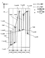
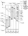
- the light irradiation device 11 includes a light source 110 capable of emitting light source light ELs, a focus lens 111, and a focus lens 111, as shown in FIG. 3, which is a perspective view showing the structure of the light irradiation device 11. It includes a multi-beam optical system 112, a galvanometer mirror 113, and an f ⁇ lens 114.
- the light source 110 emits the light source light ELo.
- the light source light ELo is, for example, light having the same characteristics as the processed light ELk (for example, at least one of type, wavelength, and energy), but may be light having characteristics different from the processed light ELk.
- the light source 110 emits pulsed light as light source light ELo, for example.
- the shorter the emission time width of the pulsed light hereinafter referred to as "pulse width", the higher the processing accuracy (for example, the formation accuracy of the riblet structure described later). Therefore, the light source 1111 may emit pulsed light having a relatively short pulse width as the light source light ELo.
- the light source 1111 may emit pulsed light having a pulse width of 1000 nanoseconds or less as the light source light ELo.
- the focus lens 111 is composed of one or more lenses, and by adjusting the position of at least a part of the lenses along the optical axis direction, the light condensing position of the light source light ELo (that is, the focal position of the light irradiation device 11). ) Is an optical element for adjusting.
- the multi-beam optical system 112 branches (in other words, separates or divides) the light source light ELo from the light source 111 into a plurality of processed light ELks.
- the multi-beam optical system 112 includes a polarizing beam splitter 1121 and 1 / as shown in FIG. 4, which is a cross-sectional view showing the structure of the multi-beam optical system 112. It includes a 4-wave plate 1122, a reflection mirror 1123, a 1/4 wave plate 1124, and a reflection mirror 1125.
- the light source light ELo from the light source 111 is incident on the separation surface 11211 of the polarization beam splitter 1121.
- the s-polarized ELs1 of the light source light ELo is reflected on the separation surface 11211.
- the p-polarized ELp2 of the light source light ELo passes through the separation surface 11211. That is, the polarization beam splitter 1121 branches the light source light ELo into s-polarized ELs1 and p-polarized ELp2.
- the s-polarized ELs1 reflected by the polarizing beam splitter 1121 passes through the 1/4 wave plate 1122. As a result, the s-polarized ELs1 are converted into the circularly polarized ELc1.
- the circularly polarized ELc1 that has passed through the 1/4 wave plate 1122 is reflected by the reflecting surface 11231 of the reflecting mirror 1123.
- the circularly polarized ELc1 reflected by the reflection mirror 1123 passes through the 1/4 wave plate 1122 again and is converted into the p-polarized ELp1.
- the p-polarized ELp1 that has passed through the 1/4 wave plate 1122 is incident on the separation surface 11211 of the polarizing beam splitter 1121.
- the p-polarized ELp2 that has passed through the polarizing beam splitter 1121 passes through the 1/4 wave plate 1124.
- the p-polarized ELp2 is converted into the circularly polarized ELc2.
- the circularly polarized ELc2 that has passed through the 1/4 wave plate 1124 is reflected by the reflecting surface 11251 of the reflecting mirror 1125.
- the circularly polarized ELc2 reflected by the reflection mirror 1125 passes through the 1/4 wave plate 1124 again and is converted into s polarized ELs2.
- the s-polarized ELs2 that have passed through the 1/4 wave plate 1124 are incident on the separation surface 11211 of the polarizing beam splitter 1121.
- the p-polarized ELp1 incident on the separation surface 11211 passes through the separation surface 11211.
- the p-polarized ELp1 that has passed through the separation surface 11211 is ejected from the multi-beam optical system 112 toward the galvanometer mirror 113 as one of the plurality of processed light ELks.
- the s-polarized ELs2 incident on the separation surface 11211 are reflected by the separation surface 11211.
- the s-polarized ELs2 reflected by the separation surface 11211 is emitted from the multi-beam optical system 112 toward the galvano mirror 113 as one of the plurality of processed light ELks.
- the polarized beam splitter 1121 not only functions as an optical system that branches the light source light ELo into s-polarized ELs1 and p-polarized ELp2, but also p-polarized ELp1 and s-polarized ELs2 that are incident on the polarized beam splitter 1121 from different directions. Also functions as an optical system that merges as a plurality of processed light ELks toward the galvanometer mirror 113.
- reflection is performed so that the incident angle of the circularly polarized ELc1 with respect to the reflecting surface 11231 of the reflecting mirror 1123 is different from the incident angle of the circularly polarized ELc2 with respect to the reflecting surface 11251 of the reflecting mirror 1125.
- the mirrors 1123 and 1125 are aligned. That is, the angle formed by the reflecting surface 11231 of the reflecting mirror 1123 and the axis along the traveling direction of the circularly polarized ELc1 is the angle formed by the reflecting surface 11251 of the reflecting mirror 1125 and the axis along the traveling direction of the circularly polarized ELc2. Reflective mirrors 1123 and 1125 are aligned so that they are different.
- the reflection mirrors 1123 and 1125 are aligned so that the circularly polarized ELc1 is vertically incident on the reflecting surface 11231 while the circularly polarized ELc2 is obliquely incident on the reflecting surface 11251.
- the axis along the traveling direction of the p-polarized ELp1 that has passed through the separation surface 11211 and the axis along the traveling direction of the s-polarized ELs2 reflected by the separation surface 11211 intersect. That is, a plurality of axes along the traveling directions of the plurality of processed light ELks emitted from the multi-beam optical system 112 intersect with each other.
- the reflection mirrors 1123 and 1125 can function as an optical system that causes the traveling directions of the plurality of processed light ELks to differ from each other.
- the plurality of processing light ELks pass through different positions on the optical surfaces intersecting the traveling directions of the plurality of processing light ELks. That is, on the optical surface intersecting the traveling directions of the plurality of processing light ELks, the plurality of processing light ELks form a plurality of beam spots, respectively.
- the coating film SF is irradiated with such a plurality of processing light ELks, as shown in FIG.
- the plurality of processing light ELks are radiated to a plurality of beam spots (that is, a plurality of beam spots) on the coating film SF. Irradiation area) is formed respectively. That is, the multi-beam optical system 112 emits a plurality of processed light ELks that are irradiated to different positions on the coating film SF. As a result, the coating film SF is simultaneously irradiated with a plurality of processing light ELks. That is, a plurality of target irradiation regions EA are simultaneously set on the coating film SF.
- the galvano mirror 113 is arranged on the optical path of a plurality of processed optical ELks.
- the galvano mirror 113 is arranged between the multi-beam optical system 112 and the f ⁇ lens 114.
- a plurality of processing light ELks emitted by the multi-beam optical system 112 scan the surface of the coating film SF (that is, a plurality of target irradiation regions EA to which the plurality of processing light ELks are each irradiated are the coating film SF.
- the plurality of processing light ELks are deflected so as to move on the surface of the.
- the galvanometer mirror 113 may allow a plurality of processed light ELks emitted by the multi-beam optical system 112 to sweep the surface of the coating film SF.
- the galvano mirror 113 includes an X scanning mirror 113X and a Y scanning mirror 113Y.
- the Y scanning mirror 113Y reflects a plurality of processed light ELks emitted by the multi-beam optical system 112 toward the X scanning mirror 113X.
- the Y scanning mirror 113Y can swing or rotate in the ⁇ X direction (that is, the rotation direction around the X axis). By swinging or rotating the Y scanning mirror 113Y, the plurality of processing light ELks scan the surface of the coating film SF along the Y-axis direction.
- the plurality of processed light ELks are swept on the surface of the coating film SF along the Y-axis direction.
- the traveling directions of the plurality of processing light ELks are changed so that the plurality of processing light ELks scan the surface of the coating film SF along the Y-axis direction. Due to the swing or rotation of the Y scanning mirror 113Y, the plurality of target irradiation regions EA move along the Y-axis direction on the coating film SF.
- the Y scanning mirror 113Y changes the relative positional relationship between the plurality of target irradiation regions EA and the coating film SF along the Y-axis direction.
- the X scanning mirror 113X reflects a plurality of processed light ELks reflected by the Y scanning mirror 113Y toward the f ⁇ lens 114.
- the X scanning mirror 113X can swing or rotate in the ⁇ Y direction (that is, the rotation direction around the Y axis). By swinging or rotating the X scanning mirror 113X, the plurality of processed light ELks scan the surface of the coating film SF along the X-axis direction.
- the plurality of processed light ELks are swept on the surface of the coating film SF along the X-axis direction.
- the traveling directions of the plurality of processing light ELks are changed so that the plurality of processing light ELks scan the surface of the coating film SF along the X-axis direction. Due to the swing or rotation of the X scanning mirror 113X, the plurality of target irradiation regions EA move along the X-axis direction on the coating film SF.
- the X scanning mirror 113X changes the relative positional relationship between the plurality of target irradiation regions EA and the coating film SF along the X-axis direction.
- the galvanometer mirror 113 may be referred to as a displacement member because the target irradiation region EA can be moved (that is, displaced) on the surface of the coating film SF.
- the f ⁇ lens 114 is arranged on the optical path of a plurality of processed light ELks from the galvano mirror 113.
- the f ⁇ lens 114 is an optical element for condensing a plurality of processed light ELks from the galvano mirror 113 on the coating film SF.
- the f ⁇ lens 114 is located on the light emitting side of the light irradiation device 11 among the optical elements included in the light irradiation device 11 (in other words, it is closest to the coating film SF or at the end of the optical path of a plurality of processed light ELks. It is a terminal optical element (located).
- the f ⁇ lens 114 may be configured to be removable from the light irradiation device 11.
- the light irradiation device 11 may include an optical element (for example, a cover lens or the like) provided on the light emitting side of the f ⁇ lens 114.
- An optical element for example, a cover lens or the like provided on the light emitting side of the f ⁇ lens 114 may be configured to be detachable from the light irradiation device 11.
- the drive system 12 under the control of the control device 2, makes the light irradiation device 11 with respect to the coating film SF (that is, with respect to the processing object S on which the coating film SF is formed on the surface). Move. That is, the drive system 12 moves the light irradiation device 11 with respect to the coating film SF so as to change the relative positional relationship between the light irradiation device 11 and the coating film SF.
- the relative positional relationship between the light irradiation device 11 and the coating film SF is changed, the relative positional relationship between the coating film SF and the plurality of target irradiation regions EA to which the plurality of processing light ELks are irradiated respectively.
- the positional relationship is also changed. Therefore, it can be said that the drive system 12 moves the light irradiation device 11 with respect to the coating film SF so as to change the relative positional relationship between the plurality of target irradiation regions EA and the coating film SF.
- the drive system 12 may move the light irradiation device 11 along the surface of the coating film SF.
- the drive system 12 since the surface of the coating film SF is a plane parallel to at least one of the X-axis and the Y-axis, the drive system 12 is irradiated with light along at least one of the X-axis and the Y-axis.
- the device 11 may be moved.
- the target irradiation region EA moves along at least one of the X-axis and the Y-axis on the coating film SF.
- the drive system 12 may move the light irradiation device 11 along the thickness direction of the coating film SF (that is, the direction intersecting the surface of the coating film SF).
- the drive system 12 may move the light irradiation device 11 along the Z-axis direction.
- the drive system 12 is a light irradiation device along at least one of the X-axis, the Y-axis, and the Z-axis, and at least one of the ⁇ X-direction, the ⁇ Y-direction, and the ⁇ Z-direction (that is, the rotation direction around the Z-axis). 11 may be moved.
- the drive system 12 supports the light irradiation device 11 and moves the supporting light irradiation device 11.
- the drive system 12 may include, for example, a first support member that supports the light irradiation device 11, and a first movement mechanism that moves the first support member.
- the accommodating device 13 includes a ceiling member 131 and a partition wall member 132.
- the ceiling member 131 is arranged on the + Z side of the light irradiation device 11.
- the ceiling member 131 is a plate-shaped member along the XY plane.
- the ceiling member 131 supports the drive system 12 via the support member 133.
- a partition wall member 132 is arranged on the outer edge (or its vicinity) of the surface of the ceiling member 131 on the ⁇ Z side.
- the partition wall member 132 is a tubular (for example, cylindrical or rectangular tubular) member extending from the ceiling member 131 toward the ⁇ Z side.
- the space surrounded by the ceiling member 131 and the partition wall member 132 serves as an accommodation space SP for accommodating the light irradiation device 11 and the drive system 12.
- the drive system 12 described above moves the light irradiation device 11 within the accommodation space SP.
- the accommodation space SP includes a space between the light irradiation device 11 and the coating film SF (particularly, a space including an optical path of the processed light ELk). More specifically, the accommodation space SP includes a space between the terminal optical element (for example, f ⁇ lens 1123) included in the light irradiation device 11 and the coating film SF (particularly, a space including an optical path of the processed light ELk). I'm out.
- Each of the ceiling member 131 and the partition wall member 132 is a member capable of blocking the processed light ELk. That is, each of the ceiling member 131 and the partition wall member 132 is opaque with respect to the wavelength of the processing light ELk. As a result, the processed light ELk propagating in the accommodation space SP does not leak to the outside of the accommodation space SP (that is, the outside of the accommodation device 13).
- Each of the ceiling member 131 and the partition wall member 132 may be a member capable of dimming the processing light ELk. That is, each of the ceiling member 131 and the partition wall member 132 may be translucent with respect to the wavelength of the processing light ELk.
- each of the ceiling member 131 and the partition wall member 132 is a member that does not transmit (that is, can shield) unnecessary substances generated by irradiation with the processing light ELk.
- the unnecessary substance at least one of the vapor and the fume of the coating film SF can be mentioned. As a result, unnecessary substances generated in the accommodation space SP do not leak to the outside of the accommodation space SP (that is, the outside of the accommodation device 13).
- the end portion of the partition wall member 132 (specifically, the end portion on the coating film SF side, and in the example shown in FIG. 1, the end portion on the ⁇ Z side) 134 is in contact with the surface of the coating film SF.
- the accommodating device 13 that is, the ceiling member 131 and the partition wall member 132 cooperates with the coating film SF to maintain the airtightness of the accommodating space SP.
- the shape thereof (particularly, the contact surface of the end portion 134 in contact with the coating film SF (in the example shown in FIG. 1). It is possible to change the shape of the ⁇ Z side surface), the same applies hereinafter).
- the shape of the end portion 134 becomes a flat shape similarly to the coating film SF.
- the shape of the end portion 134 becomes a curved surface shape similarly to the coating film SF.
- the airtightness of the accommodation space SP is improved as compared with the case where the end portion 134 cannot change its shape according to the shape of the surface of the coating film SF.
- An example of the end 134 whose shape can be changed is the end 134 formed of an elastic member (in other words, a flexible member) such as rubber.
- a bellows-shaped end portion 134a having an elastic structure may be used.
- the end portion 134 may be able to adhere to the coating film SF in a state of being in contact with the coating film SF.
- the end portion 134 may be provided with an adsorption mechanism capable of adsorbing to the coating film SF.
- the airtightness of the accommodation space SP is further improved as compared with the case where the end portion 134 does not adhere to the coating film SF.
- the end portion 134 does not have to be able to adhere to the coating film SF. Even in this case, as long as the end portion 134 comes into contact with the coating film SF, the airtightness of the accommodation space SP is still maintained accordingly.
- the partition wall member 132 is a member that can be expanded and contracted along the Z-axis direction by a drive system (for example, an actuator) (not shown) that operates under the control of the control device 2.
- the partition member 132 may be a bellows-shaped member (so-called bellows).
- the partition member 132 can be expanded and contracted by expanding and contracting the bellows portion.
- the partition member 132 may include a telescopic pipe in which a plurality of hollow cylindrical members having different diameters are combined. In this case, the partition member 132 can be expanded and contracted by the relative movement of the plurality of cylindrical members.
- the state of the partition wall member 132 is at least the first extended state in which the partition wall member 132 extends along the Z-axis direction and the length in the Z-axis direction is relatively long, and the partition wall member 132 contracts along the Z-axis direction. By doing so, it is possible to set the first reduced state in which the length in the Z-axis direction is relatively short.
- the end portion 134 When the partition member 132 is in the first extended state, the end portion 134 is in the first contact state capable of contacting the coating film SF.
- the end portion 134 when the partition member 132 is in the first reduced state, the end portion 134 is in the first non-contact state in which it does not come into contact with the coating film SF. That is, when the partition member 132 is in the first reduced state, the end portion 134 is in the first non-contact state separated from the coating film SF on the + Z side.
- the configuration for switching the state of the end portion 134 between the first contact state and the first non-contact state is not limited to the configuration in which the partition wall member 132 is expanded and contracted.
- the state of the end 134 may be switched between the first contact state and the first non-contact state by making the accommodating device 13 itself movable along the ⁇ Z direction.
- the accommodating device 13 further includes a detection device 135.
- the detection device 135 detects an unnecessary substance (that is, a substance generated by irradiation with the processing light ELk) in the accommodation space SP.
- the detection result of the detection device 135 is referred to by the control device 2 when the state of the partition wall member 132 is changed from the first extended state to the first reduced state, as will be described in detail later.
- the support device 14 supports the accommodating device 13. Since the accommodating device 13 supports the drive system 12 and the light irradiation device 11, the support device 14 substantially supports the drive system 12 and the light irradiation device 11 via the accommodating device 13.
- the support device 14 includes a beam member 141 and a plurality of leg members 142.
- the beam member 141 is arranged on the + Z side of the accommodating device 13.
- the beam member 141 is a beam-shaped member extending along the XY plane.
- the beam member 141 supports the accommodating device 13 via the support member 143.
- a plurality of leg members 142 are arranged on the beam member 141.
- the leg member 142 is a rod-shaped member extending from the beam member 141 toward the ⁇ Z side.
- the end portion of the leg member 142 (specifically, the end portion on the coating film SF side, and in the example shown in FIG. 1, the end portion on the ⁇ Z side) 144 is in contact with the surface of the coating film SF.
- the support device 14 is supported by the coating film SF (that is, by the workpiece S). That is, the support device 14 supports the accommodating device 13 in a state where the end portion 144 is in contact with the coating film SF (in other words, in a state where the support device 14 is supported by the coating film S). Similar to the end 134 of the accommodating device 13, the end portion 144 contacts the coating film SF among the end portions 144 according to the shape of the surface of the coating film SF when it comes into contact with the coating film SF.
- the end portion 144 may be attached to the coating film SF in a state of being in contact with the coating film SF.
- the end portion 144 may be provided with an adsorption mechanism capable of adsorbing to the coating film SF.
- the stability of the support device 14 is improved as compared with the case where the end portion 144 does not adhere to the coating film SF.
- the end portion 144 does not have to be able to adhere to the coating film SF.
- the beam member 141 is a member that can be expanded and contracted along at least one of the X-axis and the Y-axis (or along an arbitrary direction along the XY plane) by the drive system 15 that operates under the control of the control device 2. is there.
- the beam member 141 may include a telescopic pipe in which a plurality of tubular members having different diameters are combined. In this case, the beam member 141 can be expanded and contracted by the relative movement of the plurality of tubular members.
- the leg member 142 is a member that can be expanded and contracted along the Z-axis direction by the drive system 15 that operates under the control of the control device 2.
- the leg member 142 may include a telescopic pipe in which a plurality of tubular members having different diameters are combined.
- the leg member 142 can be expanded and contracted by the relative movement of the plurality of tubular members.
- the state of the leg member 142 is at least a second extended state in which the leg member 142 extends along the Z-axis direction and the length in the Z-axis direction is relatively long, and the leg member 142 contracts along the Z-axis direction. By doing so, it is possible to set the second reduced state in which the length in the Z-axis direction is relatively short.
- the end portion 144 When the leg member 142 is in the second extended state, the end portion 144 is in the second contact state capable of contacting the coating film SF. On the other hand, when the leg member 142 is in the second reduced state, the end portion 144 is in the second non-contact state in which it does not come into contact with the coating film SF. That is, when the leg member 142 is in the second contracted state, the end portion 144 is in the second non-contact state separated from the coating film SF on the + Z side.
- the drive system 15 moves the support device 14 with respect to the coating film SF (that is, with respect to the processing object S on which the coating film SF is formed on the surface) under the control of the control device 2. That is, the drive system 15 moves the support device 14 with respect to the coating film SF so as to change the relative positional relationship between the support device 14 and the coating film SF. Since the support device 14 supports the accommodating device 13, the drive system 15 substantially moves the accommodating device 13 with respect to the coating film SF by moving the support device 14. That is, the drive system 15 substantially moves the support device 14 with respect to the coating film SF so as to change the relative positional relationship between the accommodating device 13 and the coating film SF. Further, the accommodating device 13 supports the light irradiation device 11 via the drive system 12.
- the drive system 15 can substantially move the light irradiation device 11 with respect to the coating film SF by moving the support device 14. That is, the drive system 15 can substantially move the support device 14 with respect to the coating film SF so as to change the relative positional relationship between the light irradiation device 11 and the coating film SF. In other words, the drive system 15 may move the support device 14 with respect to the coating film SF so as to substantially change the relative positional relationship between the plurality of target irradiation regions EA and the coating film SF. it can.
- the drive system 15 expands and contracts the beam member 141 under the control of the control device 2 in order to move the support device 14. Further, the drive system 15 expands and contracts the plurality of leg members 142 under the control of the control device 2 in order to move the support device 14.
- the movement mode of the support device 14 by the drive system 15 will be described in detail later with reference to FIGS. 8 to 17.
- the exhaust device 16 is connected to the accommodation space SP via an exhaust pipe 161.
- the exhaust device 16 can exhaust the gas in the accommodation space SP.
- the exhaust device 16 can suck unnecessary substances generated by the irradiation of the processing light ELk from the accommodation space SP to the outside of the accommodation space SP by exhausting the gas in the accommodation space SP.
- this unnecessary substance is present on the optical path of the processing light ELk, it may affect the irradiation of the coating film SF with the processing light ELk. Therefore, the exhaust device 16 particularly sucks unnecessary substances together with the gas in the space from the space including the optical path of the processed light ELk between the terminal optical element of the light irradiation device 11 and the coating film SF. Unwanted substances sucked from the accommodation space SP by the exhaust device 16 are discharged to the outside of the processing system SYS via the filter 162.
- the filter 162 adsorbs unnecessary substances.
- the filter 162 may be removable or replaceable.
- the gas supply device 17 is connected to the accommodation space SP via an intake pipe 171.
- the gas supply device 17 can supply gas to the accommodation space SP.
- Examples of the gas supplied to the accommodation space SP include at least one of air, CDA (clean dry air) and an inert gas. Nitrogen gas is an example of an inert gas.
- the gas supply device 17 supplies the CDA. Therefore, the accommodation space SP becomes a space purged by the CDA. At least a part of the CDA supplied to the accommodation space SP is sucked by the exhaust device 16. The CDA sucked from the accommodation space SP by the exhaust device 16 passes through the filter 162 and is discharged to the outside of the processing system SYS.
- the gas supply device 17 particularly supplies a gas such as CDA to the optical surface 1141 on the accommodation space SP side of the f ⁇ lens 114 shown in FIG. 3 (that is, the optical surface on the accommodation space SP side of the terminal optical element of the light irradiation device 11).
- a gas such as CDA
- the optical surface 1141 faces the accommodation space SP, it may be exposed to unnecessary substances generated by irradiation with the processing light ELk. As a result, unnecessary substances may adhere to the optical surface 1141. Further, since the processing light ELk passes through the optical surface 1141, the processing light ELk passing through the optical surface 1141 may burn (that is, stick) unnecessary substances adhering to the optical surface 1141.
- Unwanted substances adhering to (and further adhering to) the optical surface 1141 may become stains on the optical surface 1141 and affect the characteristics of the processed light ELk.
- a gas such as CDA
- contact between the optical surface 1141 and an unnecessary substance is prevented. Therefore, adhesion of dirt to the optical surface 1141 is prevented. Therefore, the gas supply device 17 also functions as an adhesion prevention device for preventing the adhesion of dirt to the optical surface 1141.
- the gas supply device 17 can also function as an adhesion prevention device for removing dirt adhering to the optical surface 1141.
- the control device 2 controls the overall operation of the processing system SYSa.
- the control device 2 controls the light irradiation device 11, the drive system 12, the accommodating device 13, and the drive system 15 so that the recess C having a desired shape is formed at a desired position, as will be described in detail later. ..
- the control device 2 may include, for example, a CPU (Central Processing Unit) (or a GPU (Graphics Processing Unit) in addition to or in place of the CPU) and a memory.
- the control device 2 functions as a device that controls the operation of the processing system SYS by the CPU executing a computer program.
- This computer program is a computer program for causing the control device 2 (for example, the CPU) to perform (that is, execute) the operation described later to be performed by the control device 2. That is, this computer program is a computer program for causing the control device 2 to function so that the processing system SYSa performs an operation described later.
- the computer program executed by the CPU may be recorded in a memory (that is, a recording medium) included in the control device 2, or may be an arbitrary storage medium built in the control device 2 or externally attached to the control device 2 (that is, a storage medium). For example, it may be recorded on a hard disk or a semiconductor memory). Alternatively, the CPU may download the computer program to be executed from a device external to the control device 2 via the network interface.
- a memory that is, a recording medium
- the CPU may download the computer program to be executed from a device external to the control device 2 via the network interface.
- the control device 2 may not be provided inside the processing system SYS, and may be provided, for example, as a server or the like outside the processing system SYS.
- the control device 2 and the processing system SYSA may be connected by a wired and / or wireless network (or a data bus and / or a communication line).
- a wired network for example, a network using a serial bus type interface represented by at least one of IEEE1394, RS-232x, RS-422, RS-423, RS-485 and USB may be used.
- a network using a parallel bus interface may be used.
- a network using an Ethernet (registered trademark) compliant interface represented by at least one of 10BASE-T, 100BASE-TX and 1000BASE-T may be used.
- a network using radio waves may be used.
- An example of a network using radio waves is a network conforming to IEEE802.1x (for example, at least one of wireless LAN and Bluetooth®).
- a network using infrared rays may be used.
- a network using optical communication may be used.
- the control device 2 and the processing system SYSA may be configured so that various types of information can be transmitted and received via the network.
- control device 2 may be able to transmit information such as commands and control parameters to the processing system SYSA via the network.
- the processing system SYSa may include a receiving device that receives information such as commands and control parameters from the control device 2 via the network.
- the first control device that performs a part of the processing performed by the control device 2 is provided inside the processing system SYS
- the second control device that performs the other part of the processing performed by the control device 2 is performed.
- the control device may be provided outside the processing system SYS.
- Recording media for recording computer programs executed by the CPU include CD-ROMs, CD-Rs, CD-RWs, flexible discs, MOs, DVD-ROMs, DVD-RAMs, DVD-Rs, DVD + Rs, and DVD-RWs. , DVD + RW and optical disks such as Blu-ray (registered trademark), magnetic media such as magnetic tape, magneto-optical disks, semiconductor memories such as USB memory, and any other medium capable of storing a program are used. May be good.
- the recording medium may include a device capable of recording a computer program (for example, a general-purpose device or a dedicated device in which the computer program is implemented in a state in which it can be executed in at least one form such as software and firmware).
- each process or function included in the computer program may be realized by a logical processing block realized in the control device 2 by the control device 2 (that is, the computer) executing the computer program. It may be realized by hardware such as a predetermined gate array (FPGA, ASIC) included in the control device 2, or a logical processing block and a partial hardware module that realizes a part of the hardware are mixed. It may be realized in the form of.
- FPGA predetermined gate array
- the machining system SYSa forms a recess C in the coating film SF.
- the recess C is formed in a portion of the coating film SF that is actually irradiated with the processing light ELk. Therefore, if the position where the processing light ELk is actually irradiated on the coating film SF (that is, the position where the target irradiation region EA where the processing light ELk is scheduled to be irradiated is set) is appropriately set.
- the recess C can be formed at a desired position of the coating film SF. That is, a structure formed by the coating film SF can be formed on the object to be processed S.
- the processing system SYSa moves the surface of the coating film SF to the target irradiation region EA by using at least one of the galvano mirror 113 and the drive system 12.
- the processing system SYSa targets the area of the surface of the coating film SF to be actually irradiated with the processing light ELk (that is, the area to be processed) while the target irradiation area EA moves on the surface of the coating film SF.
- the processing light ELk is irradiated at the timing when the regions EA overlap.
- the target irradiation region EA does not overlap the region of the surface of the coating film SF where the processing light ELk should actually be irradiated during the period when the target irradiation region EA moves on the surface of the coating film SF.
- the processing light ELk is not irradiated at the timing. That is, the processing system SYSa is a region of the surface of the coating film SF that should not be actually irradiated with the processing light ELk (that is, a region that should not be processed) while the target irradiation region EA moves on the surface of the coating film SF.
- the processing light ELk is not irradiated.
- a structure formed by the coating film SF according to the pattern of the region of the coating film SF actually irradiated with the processing light ELk is formed on the processing object S.
- the processing system SYSa forms a riblet structure, which is an example of the structure by such a coating film SF, on the processing object S under the control of the control device 2.
- the riblet structure is a structure capable of reducing the resistance (particularly, frictional resistance, turbulent frictional resistance) of the surface of the coating film SF to the fluid.
- the resistance to the fluid on the surface of the work object S on which the riblet structure is formed is smaller than the resistance to the fluid on the surface of the work object S on which the riblet structure is not formed. Therefore, it can be said that the riblet structure is a structure capable of reducing the resistance of the surface of the workpiece S to the fluid.
- the fluid referred to here may be a medium (gas, liquid) flowing relative to the surface of the coating film SF.
- the medium flowing with respect to the stationary work object SF and the stationary medium distributed around the moving work object SF are examples of fluids.
- FIGS. 6 (a) and 6 (b) An example of the riblet structure is shown in FIGS. 6 (a) and 6 (b).
- the riblet structure is formed, for example, along a first direction (in the example shown in FIGS. 6 (a) and 6 (b), the Y-axis direction).
- the concave structure CP1 formed by continuously forming the concave portions C that is, the concave structure CP1 formed linearly so as to extend along the first direction
- a plurality of structures are arranged along two directions (in the example shown in FIGS. 6A and 6B, the X-axis direction).
- the riblet structure is, for example, a structure in which a plurality of concave structures CP1 extending along a first direction have a periodic direction in a second direction intersecting the first direction.
- a convex structure CP2 protruding from the periphery is substantially present between two adjacent concave structure CP1s. Therefore, in the riblet structure, for example, the convex structure CP2 extending linearly along the first direction (for example, the Y-axis direction) intersects the first direction in the second direction (for example, the X-axis direction). It can be said that it is a structure in which a plurality of elements are arranged along the line.
- the riblet structure is, for example, a structure in which a plurality of convex structures CP2 extending along the first direction have a periodic direction in the second direction intersecting the first direction.
- the riblet structure shown in FIGS. 6 (a) and 6 (b) is a periodic structure.
- the distance between two adjacent concave structure CP1s (that is, the arrangement pitch P1 of the concave structure CP1) is, for example, several microns to several hundreds of microns, but may be other sizes.
- the depth D of each concave structure CP1 (that is, the depth in the Z-axis direction) D is, for example, several microns to several hundreds of microns, but may have other sizes.
- the depth D of each concave structure CP1 may be equal to or less than the arrangement pitch P1 of the concave structure CP1.
- the depth D of each concave structure CP1 may be half or less of the arrangement pitch P1 of the concave structure CP1.
- the shape of the cross section (specifically, the cross section along the XZ plane) including the Z axis of each concave structure CP1 is a bowl-shaped curved shape, but it may be a triangle or a quadrangle. However, it may be a polygon of pentagon or more.
- the distance between two adjacent convex structure CP2s (that is, the arrangement pitch P2 of the convex structure CP2) is, for example, several microns to several hundreds of microns, but other sizes may be used.
- the height (that is, the height in the Z-axis direction) H of each convex structure CP2 is, for example, several microns to several hundreds of microns, but may have other sizes.
- the height H of each convex structure CP2 may be equal to or less than the arrangement pitch P2 of the convex structure CP2.
- the height H of each convex structure CP2 may be half or less of the arrangement pitch P2 of the convex structure CP2.
- each convex structure CP2 is a chevron shape with a curved slope, but it may be a triangle or a quadrangle. It may be a pentagon or a polygon more than a pentagon. Further, each convex structure CP2 may have a ridgeline.
- the riblet structure itself formed by the processing system SYSA may be an existing riblet structure as described in Chapter 5 of "Mechanical Engineering Handbook Basics ⁇ 4 Fluid Engineering” edited by the Japan Society of Mechanical Engineering. A detailed description of the structure itself will be omitted.
- the object to be processed S may be an object (for example, a structure) whose resistance to the fluid is desired to be reduced.
- the object to be processed S may include an object (that is, a moving body) that can move at least in part so as to travel in a fluid (for example, at least one of a gas and a liquid).
- the object to be machined S is an aircraft PL body (for example, a fuselage PL1, a main wing PL2, a vertical tail PL3, and a horizontal stabilizer PL4.
- the processing device 1 (or the processing system SYS, hereinafter the same in this paragraph) is self-supporting on the fuselage of the aircraft PL by the support device 14. You may. Alternatively, since the end portion 144 of the leg member 142 of the support device 14 can adhere to the coating film SF, the processing device 1 is suspended from the aircraft PL by the support device 14, as shown in FIG. 7 (b). It may be attached to the fuselage of the aircraft PL so as to be lowered (that is, hung).
- the processing device 1 can be attached to the coating film SF. Even when the surface of the coating film SF is inclined with respect to the horizontal plane in a state of facing upward, the coating film SF can stand on its own. Further, the processing apparatus 1 can adhere to the coating film SF so as to hang from the coating film SF even when the surface of the coating film SF is inclined downward with respect to the horizontal plane. is there. In any case, the light irradiation device 11 can be moved along the surface of the airframe by the drive system 12 and / or by the movement of the support device 14.
- the processing system SYS is applied to a processing object S such as an aircraft body (that is, a processing object S having a curved surface, an inclined surface with respect to a horizontal plane, or a surface facing downward). Also, a riblet structure can be formed by the coating film SF.
- the object to be processed S may include at least one of the vehicle body and aerodynamic parts of the automobile.
- the object to be processed S may include the hull of a ship.
- the processing object S may include a rocket body.
- the object S to be processed may include a turbine (for example, at least one of a hydraulic turbine, a wind turbine, and the like, particularly its turbine blade).
- the workpiece S may include parts that make up an object that is at least partially movable so as to travel in the fluid.
- the object to be processed S may include an object whose at least a part is fixed in a flowing fluid.
- the object to be processed S may include a bridge girder installed in a river or the sea.
- the object S to be processed may include a pipe through which a fluid flows. In this case, the inner wall of the pipe may be the surface of the work object S described above.
- An example of the object to be processed S given here is a relatively large object (for example, an object having a size on the order of several meters to several hundred meters).
- the size of the light irradiation device 11 is smaller than the size of the object to be processed S.
- the object to be processed S may be an object of any size.
- the object S to be processed may be an object having a size on the order of kilometers, centimeters, millimeters, or micrometers.
- the characteristics of the riblet structure described above may be set to appropriate characteristics so that the effect of reducing friction can be appropriately obtained depending on what kind of object the workpiece S is. That is, the characteristics of the riblet structure described above may be optimized so that the effect of reducing friction can be appropriately obtained depending on what kind of object the workpiece S is. More specifically, the characteristics of the riblet structure are the type of fluid distributed around the work object S in use (that is, in operation), the relative velocity of the work object S with respect to the fluid, and the work object. Depending on at least one such as the shape of S, it may be set to an appropriate characteristic in which the effect of reducing friction is appropriately obtained.
- the characteristics of the riblet structure described above are such that the effect of reducing friction can be appropriately obtained depending on what kind of object S is the object to be processed and in which part of the object the riblet structure is formed. It may be set to an appropriate characteristic. For example, when the object S to be processed is an aircraft PL, the characteristics of the riblet structure formed on the fuselage PL1 and the characteristics of the riblet structure formed on the main wing PL2 may be different.
- the characteristics of the riblet structure may include the size of the riblet structure.
- the size of the riblet structure includes at least one such as the arrangement pitch P1 of the concave structure CP1, the depth D of each concave structure CP1, the arrangement pitch P2 of the convex structure CP2, and the height H of each convex structure CP2. May be good.
- the characteristics of the riblet structure may include the shape of the riblet structure (for example, the shape of the cross section including the Z axis (specifically, the cross section along the XZ plane)).
- the characteristics of the riblet structure may include a stretching direction of the riblet structure (that is, a stretching direction of the concave structure CP1).
- the characteristics of the riblet structure may include the formation position of the riblet structure.
- the characteristics of the riblet structure may be determined based on a simulation model that simulates the workpiece S.
- the characteristics of the riblet structure are determined based on a simulation model that simulates the workpiece S moving in the fluid (in other words, simulating the flow of the fluid around the moving workpiece S). May be good.
- the control device 2 (or another arithmetic unit that performs calculations based on the simulation model) may determine the characteristics of the riblet structure that appropriately obtains the effect of reducing friction based on the fluid simulation model. Good.
- the control device 2 may then control the processing device 1 to form a riblet structure having the determined properties, based on the riblet information about the properties of the determined (ie, optimized) riblet structure.
- the riblet information may include, for example, information indicating what size, shape, and position of the concave structure CP1 in the stretching direction is formed on the object to be processed S.
- the riblet information may include, for example, information indicating what size, shape, and position of the concave structure CP1 in the stretching direction is formed in the machining object S in association with the simulation model.
- the characteristics of the riblet structure are simulations that simulate the processing object S. It may be determined based on the model. That is, in any machining system in which the workpiece S is machined to form a riblet structure, the characteristics of the riblet structure are optimized and optimized so that the friction reduction effect can be appropriately obtained based on the fluid simulation model. A riblet structure having optimized characteristics may be formed based on the riblet information regarding the characteristics of the riblet structure.
- the plurality of processed light ELks are deflected by the galvano mirror 113.
- the galvano mirror 113 corresponds to each of the plurality of processing light ELks at a desired timing while moving the plurality of target irradiation regions EA on the surface of the coating film SF along the Y-axis direction.
- a plurality of scanning operations for irradiating the target irradiation region EA to be performed and a step operation for moving the plurality of target irradiation region EA on the surface of the coating film SF by at least a predetermined amount along the X-axis direction are alternately repeated.
- the processed light ELk is deflected.
- the Y axis may be referred to as a scan axis
- the X axis may be referred to as a step axis.
- the control device 2 provides a plurality of processed shot regions SA on the surface of the coating film SF (particularly, the region of the coating film SF where the riblet structure should be formed). It may be set.
- Each processing shot region SA corresponds to a region on the coating film SF capable of scanning a plurality of processing light ELks under the control of the galvanometer mirror 113 while the light irradiation device 11 is stationary with respect to the coating film SF.
- the shape of each processed shot region SA is quadrangular, but the shape is arbitrary.
- the control device 2 controls the light irradiation device 11 so as to irradiate at least a part of one processing shot region SA (for example, SA1) with a plurality of processing light ELks deflected by the galvanometer mirror 113.
- a riblet structure is formed in the processed shot region SA (SA1).
- the control device 2 controls at least one of the drive systems 12 and 15 so as to move the light irradiation device 11 with respect to the coating film SF, so that the light irradiation device 11 can be moved to another processing shot region SA (for example,).
- the SA2) is arranged at a position where a plurality of processing light ELks can be irradiated.
- control device 2 controls the light irradiation device 11 so as to irradiate at least a part of the other processing shot region SA (SA2) with the plurality of processing light ELks deflected by the galvanometer mirror 113.
- SA processing shot region
- a riblet structure is formed in the processing shot region SA of.
- the control device 2 forms a riblet structure by repeating the following operations for all the machined shot areas SA1 to SA16.
- the control device 2 When forming the riblet structure in each machining shot region SA, the control device 2 should be formed in each machining shot region SA from the riblet information regarding the characteristics of the riblet structure optimized based on the above-mentioned simulation model. Information corresponding to the characteristics of the riblet structure is acquired, and a riblet structure having characteristics optimized for each machining shot region SA is formed in each machining shot region SA based on the acquired information.
- the operation of forming the riblet structure in the machining shot regions SA1 to SA4 shown in FIG. 8 will be described as an example.
- an example in which two machining shot regions SA adjacent to each other along the X-axis direction are located in the accommodation space SP will be described.
- the same operation is still performed.
- the operation of forming the riblet structure shown below is only an example, and the processing system SYS may perform an operation different from the operation shown below to form the riblet structure.
- the processing system SYS may perform any operation as long as it is possible to irradiate the processing object S with a plurality of processing light ELks to form a riblet structure on the processing object S.
- the control device 2 controls the drive system 15 so that the accommodation device 13 is arranged at the first accommodation position where the machining shot areas SA1 and SA2 are located in the accommodation space SP.
- the support device 14 is moved with respect to the coating film SF. That is, the control device 2 moves the accommodating device 13 supported by the support device 14 so that the machining shot areas SA1 and SA2 are covered by the accommodating device 13.
- the control device 2 controls the drive system 12 so that the light irradiation device 11 is arranged at the first irradiation position capable of irradiating the processing shot region SA1 with a plurality of processing light ELks. The light irradiation device 11 is moved relative to the light irradiation device 11.
- the partition wall member 132 is in the first extended state. Therefore, the end 134 of the partition member 132 comes into contact with and adheres to the coating film SF.
- the plurality of leg members 142 are in the second extended state. Therefore, the end portions 144 of the plurality of leg members 142 come into contact with and adhere to the coating film SF.
- the control device 2 uses the light irradiation device 11 (particularly, the galvano mirror 113) so that the plurality of processing light ELks scan the processing shot region SA1.
- the control device 2 scans a certain area in the machined shot area SA1 along the Y-axis direction in order to perform the scanning operation described above, so that the Y of the galvano mirror 113 Controls the scanning mirror 113Y.
- the light source 110 emits the light source light ELo.
- the multi-beam optical system 112 emits a plurality of processed light ELks while the scanning operation is being performed.
- the control device 2 rotates the X scanning mirror 113X of the galvano mirror 113 by a unit step amount in order to perform the step operation described above. While the step operation is being performed, the light source 110 does not emit the light source light ELo. As a result, the multi-beam optical system 112 does not emit a plurality of processed light ELks while the step operation is being performed. After that, in order to perform the scanning operation described above, the control device 2 scans a certain area in the processing shot area SA1 along the Y-axis direction so that the plurality of processing light ELks scan the Y scanning mirror 113Y of the galvano mirror 113. To control.
- control device 2 alternately repeats the scanning operation and the step operation to process the entire processing shot area SA1 (or a part of the processing shot area SA1 where the riblet structure should be formed).
- the galvano mirror 113 is controlled so that the optical ELk scans. While the step operation is being performed, the light source light ELo may be emitted from the light source 110 to emit a plurality of processed light ELks.
- FIG. 11 which is a plan view showing the scanning locus of the processing light ELk (that is, the moving locus of the target irradiation region EA) during the period in which the scanning operation and the step operation are repeated.
- No. 1 sequentially scans a plurality of scan areas SCA set in the machining shot area SA.
- FIG. 11 shows an example in which six scan areas SCA # 1 to SCA # 6 are set in the machining shot area SA.
- Each scan area SCA is an area scanned by a plurality of processing light ELks irradiated in one scan operation (that is, a series of scan operations that do not sandwich a step operation).
- Each scan area SCA is an area in which a plurality of target irradiation areas EA move in one scan operation.
- the target irradiation area EA moves from the scan start position SC_start of each scan area SCA toward the scan end position SC_end in one scan operation.
- Such a scanning region SCA is typically a region extending along the Y-axis direction (that is, the scanning direction of the plurality of processing light ELks).
- the plurality of scan areas SCA are arranged along the X-axis direction (that is, the direction intersecting the scan directions of the plurality of processed light ELks).
- the machining system SYSa starts the scanning operation from, for example, one scan area SCA located on the most + X side or the most ⁇ X side of the plurality of scan area SCA set in a certain machining shot area SA.
- FIG. 11 shows an example in which the processing system SYSa starts the scanning operation from the shot area SCA # 1 located on the most ⁇ X side.
- the control device 2 can irradiate the scan start position SC_start # 1 of the scan area SCA # 1 (for example, the end on the ⁇ Y side in the scan area SCA # 1 or its vicinity) with the processing light ELk.
- the galvano mirror 113 is controlled so as to be.
- the control device 2 controls the galvanometer mirror 113 so that the target irradiation region EA is set at the scan start position SC_start # 1 of the scan region SCA # 1.
- the processing system SYSa performs a scanning operation on the scanning area SCA # 1.
- the control device 2 has a scan start position SC_start # 1 in the scan area SCA # 1 to a scan end position SC_end # 1 in the scan area SCA # 1 (for example, an end portion on the + Y side in the scan area SCA # 1).
- the galvanometer 113 is controlled so that the plurality of target irradiation regions EA move toward (or in the vicinity thereof).
- control device 2 controls the light irradiation device 11 so that each of the plurality of processing light ELks irradiates the corresponding target irradiation region EA at a desired timing.
- the scan area SCA # 1 is scanned by the plurality of processing light ELks.
- FIG. 11 shows the movement locus of one target irradiation area EA in each scan area SCA for the sake of simplification of the drawing, in reality, a plurality of target irradiation areas in each scan area SCA are shown. EA moves. That is, in FIG. 11, for the sake of simplification of the drawing, the scanning locus of one processing light ELk in each scanning area SCA is shown, but in reality, each scanning area SCA is scanned by a plurality of processing light ELks. Will be done.
- the processing system SYSa performs a step operation in order to perform the scanning operation for another scanning area SCA different from the scanning area SCA # 1.
- the control device 2 has a scan start position SC_start # 2 (for example, ⁇ Y in the scan area SCA # 2) of the scan area SCA # 2 adjacent to the scan area SCA # 1 along the X-axis direction.
- the galvano mirror 113 is controlled so that the processing light ELk can be applied to the side end (or its vicinity). That is, the control device 2 controls the galvanometer mirror 113 so that the target irradiation region EA is set at the scan start position SC_start # 2 of the scan region SCA # 2.
- the target irradiation position EA moves along the X-axis direction and the Y-axis direction, respectively.
- the amount of movement of the target irradiation position EA in the X-axis direction may be the same as the size of the scan region SCA in the X-axis direction.
- the amount of movement of the target irradiation position EA in the Y-axis direction may be the same as the size of the scan region SCA in the Y-axis direction.
- the processing system SYSa performs a scanning operation on the scanning area SCA # 2.
- the control device 2 has a scan start position SC_start # 2 in the scan area SCA # 2 to a scan end position SC_end # 2 in the scan area SCA # 2 (for example, an end portion on the + Y side in the scan area SCA # 2).
- the galvano mirror 113 is controlled so that the plurality of target irradiation regions EA move toward or near the target irradiation region EA.
- the control device 2 controls the light irradiation device 11 so that each of the plurality of processing light ELks irradiates the corresponding target irradiation region EA at a desired timing. As a result, the scan area SCA # 2 is scanned by the plurality of processing light ELks.
- the scanning direction of the processing light ELk by the scanning operation is fixed in the + Y axis direction.
- the moving direction of the target irradiation area EA by the scanning operation is fixed in the + Y axis direction. That is, in the example shown in FIG. 11, the scanning directions of the processed light ELk (that is, the moving direction of the target irradiation region EA, the same applies hereinafter) by the scanning operation performed a plurality of times in the processed shot region SA are the same.
- the scanning directions of the plurality of processing light ELks that scan the plurality of scanning areas SCA are the same as each other.
- the moving directions of the target irradiation area EA within the plurality of scan area SCA are the same as each other. Specifically, the scanning direction of the processed light ELk by the scanning operation performed on the scan area SCA # 1, the scanning direction of the processed light ELk by the scanning operation performed on the scan area SCA # 2, ... , The scanning directions of the processing light ELk by the scanning operation performed on the scanning area SCA # 6 are the same as each other. However, as will be described later in a modified example, the scanning direction of the processed light ELk by the scanning operation performed on one scan area SCA and the scanning of the processed light ELk by the scanning operation performed on the other scan area SCA. The direction may be different. The scanning direction of the processing light ELk by the scanning operation performed on one scanning area SCA may be changed during the scanning operation.
- the width of the region scanned by the processing light ELk (that is, the width of the processing shot region SA, particularly the width in the X-axis direction) is the light irradiation device 11. (Especially the width in the X-axis direction).
- the control device 2 controls the drive system 15 so that the plurality of leg members 142 are maintained in the second extended state during the period in which the light irradiation device 11 is irradiating the processing light ELk. As a result, the end portions 144 of the plurality of leg members 142 continue to adhere to the coating film SF. As a result, the stability of the support device 14 is improved, and the possibility that the target irradiation region EA of the processing light ELk is unintentionally displaced on the coating film SF due to the instability of the support device 14 is reduced. ..
- the support device 14 can stand on the coating film SF (or can adhere to the coating film SF so as to hang from the coating film SF) during at least a part of the period during which the light irradiation device 11 is irradiating the light EL. As long as it is, a part of the plurality of leg members 142 may be in the second reduced state.
- the control device 2 has a drive system (not shown) that expands and contracts the partition member 132 so that the partition member 132 is maintained in the first extended state during the period when the light irradiation device 11 is irradiating the processing light ELk. Control. As a result, the end 134 of the partition member 132 continues to adhere to the coating film SF. As a result, since the airtightness of the accommodation space SP is maintained, the processed light ELk propagating in the accommodation space SP does not leak to the outside of the accommodation space SP (that is, the outside of the accommodation device 13). Further, unnecessary substances generated in the accommodation space SP do not leak to the outside of the accommodation space SP (that is, the outside of the accommodation device 13).
- the control device 2 detects that at least a part of the end portion 134 is separated from the coating film SF during the period in which the light irradiation device 11 is irradiating the processing light ELk, the control device 2 irradiates the processing light ELk.
- the light irradiation device 11 may be controlled so as to stop.
- the light irradiation device 11 can irradiate the processing shot region SA2 with a plurality of processing light ELks from the first irradiation position.
- the drive system 12 is controlled so as to move to the irradiation position.
- the control device 2 controls the light irradiation device 11 so that the light irradiation device 11 does not irradiate the processed light ELk.
- the control device 2 uses the light irradiation device 11 (particularly, the galvano mirror 113) so that the plurality of processed light ELks scan the processed shot region SA2.
- the control device 2 alternately repeats the above-mentioned scanning operation and the above-mentioned step operation to form the entire machining shot region SA2 (or a part of the machining shot region SA2 where the riblet structure should be formed).
- the light irradiation device 11 is controlled.
- a riblet structure is formed in the processed shot region SA2.
- the plurality of recesses CP1 constituting the riblet structure in the machining shot region SA1 are the plurality of recesses constituting the riblet structure in the machining shot region SA2 (or other machining shot region SA) adjacent to the machining shot region SA1. It may be formed so as to be continuously connected to each of the CP1s. Alternatively, the plurality of recesses CP1 constituting the riblet structure in the machined shot region SA1 may be formed so as not to be connected to each other with each of the plurality of recesses CP1 forming the riblet structure in the machined shot area SA2.
- the continuous length of one recess CP1 formed as a result of scanning the machining light ELk in the machining shot region SA is the size of the machining shot region SA (particularly, in the Y-axis direction which is the scanning direction of the machining light ELk). Size) depends. Therefore, when the size of the machining shot region SA is large enough to realize the continuous length in which the riblet structure can fulfill the above-mentioned functions, the plurality of recesses CP1 constituting the riblet structure in the machining shot region SA1 are machined. It may be formed so as not to be connected to each of the plurality of recesses CP1 constituting the riblet structure in the shot region SA2.
- the continuous length at which the riblet structure can perform the above-mentioned functions is the airspeed and turbulence phenomenon during aircraft use (typically during cruising). According to the calculation based on the frequency, it is about several mm. Therefore, when the machining shot region SA having a size larger than about several mm in the Y-axis direction can be set on the surface of the coating film SF, a plurality of recesses CP1 constituting the riblet structure in the machining shot region SA1 May be formed so as not to be connected to each of the plurality of recesses CP1 constituting the riblet structure in the machined shot region SA2.
- the control device 2 moves the support device 14 (that is, the accommodation device 13). By moving it), the drive system 15 is controlled so that the machining shot region SA in which the riblet structure has not yet been formed is newly located in the accommodation space SP.
- the control device 2 expands and contracts the partition member 132 so that the state of the partition member 132 switches from the first extended state to the first contracted state. To control. As a result, the end 134 of the partition member 132 is separated from the coating film SF.
- the control device 2 controls the light irradiation device 11 so that the light irradiation device 11 does not irradiate the processing light ELk. Therefore, even if the end portion 134 is separated from the coating film SF, there is no possibility that at least one of the processed light ELk and the unnecessary substance leaks to the outside of the accommodating device 13.
- the control device 2 determines whether or not to switch the partition wall member 132 from the first extended state to the first reduced state based on the detection result of the detection device 135 that detects unnecessary substances in the accommodation space SP. You may.
- the control device 2 When unnecessary substances remain in the accommodation space SP, the control device 2 does not have to switch the partition wall member 132 from the first extended state to the first reduced state. In this case, the exhaust device 16 continues to suck the unnecessary substances remaining in the accommodation space SP. On the other hand, when no unnecessary substance remains in the accommodation space SP, the control device 2 may switch the partition wall member 132 from the first extended state to the first reduced state.
- control device 2 moves with respect to the coating film SF with the movement of the support device 14 among the plurality of leg members 142 (particularly, the contracted extension of the beam member 141 as described later).
- the drive system 15 is controlled so that the state of the leg member 142 of the portion is switched from the second extended state to the second contracted state.
- the leg member 142 that moves with respect to the coating film SF with the extension of the beam member 141 that has been reduced is typically the moving direction of the support device 14 among the plurality of leg members 142 (that is, the accommodating device 13).
- the leg member 142 is located on the front side in the moving direction). In the example shown in FIG.
- the support device 14 moves toward the + X side, and the leg member 142 located on the front side in the moving direction of the support device 14 is the leg member 142 located on the + X side.
- the leg member 142 located on the front side in the moving direction of the support device 14 will be referred to as a "front leg member 142".
- the end portion 144 of the front leg member 142 is separated from the coating film SF.
- the control device 2 moves the accommodating device 13 from the first accommodating position to the second accommodating position where the processing shot areas SA3 and SA4 are located in the accommodating space SP.
- the drive system 15 is controlled. Specifically, the control device 2 controls the drive system 15 so that the beam member 141 extends along the moving direction of the support device 14. As a result, the beam member 141 extends while supporting the accommodating device 13 (furthermore, supporting the light irradiation device 11 supported by the accommodating device 13). Further, in parallel with the movement of the support device 14, the control device 2 allows the light irradiation device 11 to irradiate the processing shot region SA3 with a plurality of processing light ELks from the second irradiation position.
- the drive system 12 is controlled so as to move to the third irradiation position.
- the control device 2 controls the partition member 2 so that the partition member 132 is maintained in the first reduced state. It controls a drive system (not shown) that expands and contracts 132.
- the movement of the support device 14 that is, the movement of the accommodating device 13
- the coating film SF is not damaged by the contact between the end portion 134 and the coating film SF during the movement of the support device 14.
- the contact between the end 134 and the coating film SF does not hinder the movement of the support device 14, at least a part of the end 134 during at least a part of the period in which the support device 14 is moving. May be in contact with the coating film SF. If the coating film SF is not damaged by the contact between the end 134 and the coating film SF during the movement of the support device 14, the end 134 may have at least a part of the period during which the support device 14 is moving. At least a part may be in contact with the coating film SF.
- the control device 2 controls the drive system 15 so that the front leg member 142 is maintained in the second contracted state.
- the movement of the support device 14 (that is, the movement of the accommodating device 13) is not hindered by the contact between the end portion 144 of the front leg member 142 and the coating film SF.
- the coating film SF is not damaged by the contact between the end portion 144 and the coating film SF during the movement of the support device 14.
- the contact between the end portion 144 and the coating film SF does not hinder the movement of the support device 14, at least a part of the end portion 144 during at least a part of the period in which the support device 14 is moving. May be in contact with the coating film SF.
- the end 144 may have at least a part of the period during which the support device 14 is moving. At least a part may be in contact with the coating film SF.
- the control device 2 keeps the leg members 142 other than the front leg members 142 in the first extended state among the plurality of leg members 142.
- the drive system 15 is controlled.
- the support device 14 can stand on the coating film SF (or is suspended from the coating film SF) as in the case where all the end portions 144 of the plurality of leg members 142 are in contact with the coating film SF. It can adhere to the coating film SF).
- control device 2 controls the light irradiation device 11 so that the light irradiation device 11 does not irradiate the processing light ELk.
- the control device 2 expands and contracts the partition wall member 132 so that the partition wall member 132 switches from the first contracted state to the first extended state. Controls a drive system (not shown). As a result, the end 134 of the partition member 132 comes into contact with and adheres to the coating film SF. Further, the control device 2 controls the drive system 15 so that the front leg member 142 switches from the second contracted state to the second extended state. As a result, the end portion 144 of the front leg member 142 comes into contact with and adheres to the coating film SF.
- the extension operation of the partition wall member 132 and the extension operation of the front leg member 142 may be performed at the same time, or may be performed with a time lag.
- the coating film SF is accompanied by the movement of the support device 14 among the plurality of leg members 142 (particularly, as will be described later, the extension of the beam member 141 is reduced).
- the drive system 15 is controlled so that the state of at least a part of the leg members 142 moving with respect to the leg member 142 is switched from the second extended state to the second contracted state.
- the leg member 142 that moves with respect to the coating film SF as the extended beam member 141 shrinks is typically a leg located on the rear side of the plurality of leg members 142 in the moving direction of the support device 14. It is a member 142. In the example shown in FIG.
- the leg member 142 located on the rear side in the moving direction of the support device 14 is the leg member 142 located on the ⁇ X side.
- the leg member 142 located on the rear side in the moving direction of the support device 14 will be referred to as a “rear leg member 142”.
- the end portion 144 of the rear leg member 142 is separated from the coating film SF.
- control device 2 controls the drive system 15 so that the beam member 141 extending along the moving direction of the support device 14 shrinks.
- the control device 2 controls the drive system 15 so that the rear leg member 142 switches from the second reduced state to the second extended state. As a result, the end portion 144 of the rear leg member 142 comes into contact with and adheres to the coating film SF.
- the control device 2 sets the light irradiation device 11 so that the plurality of processing light ELks scan the processing shot areas SA3 and SA4 in the same manner as when the plurality of processing light ELks scan the processing shot areas SA1 and SA2.
- a plurality of processing light ELks are applied to the surface of the coating film SF (particularly, the region of the coating film SF where the riblet structure should be formed).
- a riblet structure formed by the coating film SF is formed on the object to be processed S.
- the processing light ELk is applied to the processing object S (particularly, the coating film SF formed on the surface thereof).
- a riblet structure formed by the coating film SF can be formed on the surface of the object to be processed S.
- the machining system SYSa creates a riblet structure relatively easily and in a relatively short time as compared with a machining device that forms a riblet structure by scraping the surface of the object S to be machined with a cutting tool such as an end mill. Can be formed.
- the processing system SYSa can simultaneously irradiate a plurality of processing light ELks to form a plurality of concave structure CP1s at the same time. Therefore, the throughput related to the formation of the riblet structure is improved as compared with the processing system in which only a single concave structure CP1 can be formed at a time by irradiating a single processing light ELk.
- the processing system SYSa can deflect a plurality of processing light ELks with the galvano mirror 113 to scan the coating film SF at a relatively high speed. Therefore, the throughput for forming the riblet structure is improved.
- the processing system SYSa processes the coating film SF formed on the surface of the processing object S instead of directly processing the processing object S, thereby forming a riblet on the surface of the processing object S. Structures can be formed. Therefore, with a processing system that forms a riblet structure by newly adding (for example, pasting) a special material for forming the riblet structure to the surface of the processing object S (that is, the surface of the coating film SF). In comparison, an increase in the weight of the workpiece S due to the formation of the riblet structure can be avoided.
- the processing system SYSa since the processing system SYSa does not directly process the object S to be processed, the riblet structure can be reshaped relatively easily. Specifically, when reforming the riblet structure, the riblet structure is first peeled off by the coating film SF, and then a new coating film SF is applied. After that, the processing system SYSa can form a new riblet structure by processing the newly applied coating film SF. Therefore, deterioration of the riblet structure (for example, breakage) can be dealt with relatively easily by reforming the riblet structure.
- the processing system SYSA does not directly process the processing object S
- the riblet structure can be formed on the surface of the processing object S which is difficult to be directly processed or the riblet structure is not originally formed. it can. That is, if the coating film SF is processed by the processing system SYS after the coating film SF is applied to the surface of the object S to be processed, the riblet structure can be formed relatively easily.
- the processing operation of processing the processing object S is to apply the coating film SF to the processing object S (that is, to form the coating film SF).
- the operation of processing the coating film SF (for example, the operation of partially removing the coating film SF) may be included.
- the operation of applying the coating film SF to the object to be processed S may be performed by the processing system SYS.
- the processing system SYSA may be provided with a coating device for applying the coating film SF to the processing object S.
- the operation of applying the coating film SF to the object to be processed S may be performed outside the processing system SYS.
- the operation of applying the coating film SF to the object S to be processed may be performed by an external coating device of the processing system SYS.
- the processing system SYSa can form a riblet structure by the coating film SF.
- the coating film SF usually has relatively high durability to an external environment (for example, at least one of heat, light, wind, etc.). Therefore, the processing system SYSa can relatively easily form a riblet structure having relatively high durability.
- the optical path of the processed light ELk between the terminal optical element of the light irradiation device 11 and the coating film SF is included in the accommodation space SP. Therefore, the processing light ELk (or the processing concerned) irradiated to the coating film SF is compared with the processing system in which the optical path of the processing light ELk is not included in the accommodation space SP (that is, it is open to the open space). It is possible to appropriately prevent the scattered light or the reflected light from the coating film SF of the optical ELk from propagating (in other words, being scattered) around the processing system SYS. Further, it is possible to appropriately prevent unnecessary substances generated by the irradiation of the processing light ELk from propagating (in other words, scattering) around the processing system SYS.
- the light irradiation device 11 is supported by the support device 14 that can move on the coating film SF. Therefore, the processing system SYSa can process the coating film SF that spreads over a relatively wide range relatively easily. That is, the processing system SYSa can form a riblet structure by the coating film SF over a relatively wide range on the surface of the processing object S. Further, since the processing system SYSa does not have to move the processing object S, the riblet structure can be relatively easily formed on the surface of the relatively large or heavy processing object S.
- the processing system SYSa can suck the unnecessary substances generated by the irradiation of the processing light ELk to the outside of the accommodation space SP by using the exhaust device 16. Therefore, the irradiation of the coating film SF with the processing light ELk is hardly hindered by unnecessary substances. Therefore, the irradiation accuracy of the processing light ELk is improved as compared with a processing system that does not have the exhaust device 16 (that is, the irradiation of the coating film SF with the processing light ELk may be hindered by unnecessary substances). .. As a result, the accuracy of forming the riblet structure is improved.
- the processing system SYSa uses the gas supply device 17 to prevent the f ⁇ lens 114 from adhering to the optical surface 1141 (that is, the optical surface on the accommodation space SP side of the terminal optical element of the light irradiation device 11). be able to. Therefore, as compared with the processing apparatus not provided with the gas supply apparatus 17, the possibility that the irradiation of the coating film SF with the processing light ELk is hindered by the dirt adhering to the optical surface 1141 is reduced. Therefore, the irradiation accuracy of the processed light ELk is improved. As a result, the accuracy of forming the riblet structure is improved.
- the multi-beam optical system 112 uses a polarizing beam splitter 1121 to split the light source light ELo into a plurality of processed light ELks. Therefore, the multi-beam optical system 112 can suppress energy loss (for example, light attenuation) in the process of branching the light source light ELo into a plurality of processed light ELks.
- the processing system SYSa uses a plurality of processing light ELks having relatively high intensities as the coating film SF as compared with the case where the energy loss in the process of branching the light source light ELo into a plurality of processing light ELks is not suppressed.
- the object S to be processed can be processed by irradiating. Therefore, the throughput related to the formation of the riblet structure is improved as compared with the case where the coating film SF is irradiated with a plurality of processing light ELks having relatively low intensities to process the processing object S.
- the processing system SYSA uses a multi-beam optical system not provided with a polarizing beam splitter 1121 to convert the light source light ELo into a plurality of processing light ELks. You may branch.
- the light source light ELo is set to the first light EL1 and the second light EL2 (for example, the states are different or different.
- An optical system 1121' including an optical element (eg, at least one of a beam splitter, a half mirror and a dichroic mirror) that branches into the same first optical EL1 and second optical EL2) and the first optical EL1 from the optical system 1121'.
- an optical element for example, at least one of a reflection optical element such as a reflection mirror and a refraction optical element such as a lens
- returns the third optical EL3 to the optical system 1121' From the optical system 1123'and the optical system 1121' including an optical element (for example, at least one of a reflection optical element such as a reflection mirror and a refraction optical element such as a lens) that returns the third optical EL3 to the optical system 1121'.
- an optical system 1125' including an optical element (for example, at least one of a reflective optical element such as a reflecting mirror and a refracting optical element such as a lens) that returns the second optical EL2 to the optical system 1121' as the fourth optical EL4.
- the multi-beam optical system 112 in which the optical system 1121'merges the third optical EL3 from the optical system 1123' and the fourth optical EL4 from the optical system 1125' and emits them as a plurality of processed optical ELks toward the galvanometer mirror 113. ' May be used to branch the light source light ELo into a plurality of processing light ELks.
- the optical system 1121', the optical system 1123', and the optical system 1125' intersect so that a plurality of axes along the traveling directions of the plurality of processed light ELks emitted from the multi-beam optical system 112' intersect. May be aligned.
- the polarization beam splitter 1121 included in the multi-beam optical system 112 described above corresponds to a specific example of the optical system 1121'.
- the 1/4 wave plate 1122 and the reflection mirror 1123 included in the multi-beam optical system 112 described above correspond to a specific example of the optical system 1123'.
- the 1/4 wave plate 1124 and the reflection mirror 1125 included in the multi-beam optical system 112 described above correspond to a specific example of the optical system 1125'.
- the polarized beam splitter 1121 not only functions as an optical system for branching the light source light ELo into s-polarized ELs1 and p-polarized ELp2, but also incidents on the polarized beam splitter 1121 from different directions. It also functions as an optical system that merges polarized ELp1 and s-polarized ELs2 as a plurality of processed light ELks directed toward the galvanometer mirror 113.
- an optical system that branches the light source light ELo into s-polarized ELs1 and p-polarized ELp2 for example, a polarized beam splitter
- an optical system that merges the p-polarized ELp1 and s-polarized ELs2 as a plurality of processed light ELks for example, polarized light.
- the multi-beam optical system 112 can be downsized as compared with the case where the beam splitter) is separately provided.
- the processing system SYSb of the second embodiment branches the light source light ELo into two processing light ELks in that the light source light ELo can be branched into three or more processing light ELks. Different from system SYS.
- the processing system SYSb is provided with a light irradiation device 11b instead of the light irradiation device 11 in comparison with the above-mentioned processing system SYSa in order to branch the light source light ELo into three or more processing light ELks. different.
- the light irradiation device 11b is different from the light irradiation device 11 in that it includes a plurality of multi-beam optical systems 112.
- Other features of the machining system SYS of the first modification may be the same as the other features of the machining system SYS described above.
- the plurality of multi-beam optical systems 112 are connected in multiple stages in series along the optical path. That is, in the plurality of multi-beam optical systems 112, the plurality of processed light ELks emitted by one multi-beam optical system 112 are connected to another multi-beam optical system 112 connected to the next stage of one multi-beam optical system 112. It is arranged so as to be incident as a plurality of light source lights ELo.
- a wave plate is placed on the optical path between the one multi-beam optical system 112 and the other multi-beam optical system 112 connected to the next stage of the one multi-beam optical system 112.
- 115b is arranged. Therefore, the plurality of processed light ELks emitted by one multi-beam optical system 112 are incident on the other multi-beam optical system 112 as a plurality of light source lights ELo via the wave plate 115b.
- the wave plate 115b is an optical element capable of changing the polarization state of each processed light ELk passing through the wave plate 115b.
- the wave plate 115b is, for example, a 1/4 wave plate, but may be another type of wave plate (for example, at least one of a 1/2 wave plate, a 1/8 wave plate, and a 1-wave plate).
- the wave plate 115b may be capable of converting each processed light ELk into circularly polarized light (or polarized light other than linearly polarized light or non-polarized light).
- the wave plate 115b is a 1/4 wavelength plate, the wave plate 115b can convert each processed light ELk which is linearly polarized light into circularly polarized light.
- the wave plate 115b may polarize each processed light ELk (or other than linearly polarized light). It can be converted to polarized or unpolarized).
- the plate thickness of the wave plate 115b may be set to a desired plate thickness capable of changing the polarization state of each processed light ELk to a desired state.
- the direction of the optical axis of the wave plate 115b may be set to a desired direction in which the polarization state of each processed light ELk can be changed to a desired state.
- each processed light ELk emitted by one multi-beam optical system 112 is incident on the other multi-beam optical system 112 as incident light ELi after the polarization state is changed.
- each of the plurality of incident light ELi is branched into a plurality of processed light ELks, as in the case where the incident light source light ELo is branched into a plurality of processed light ELks.
- the number of processed light ELks emitted by the other multi-beam optical system 112 is larger than the number of processed light ELks emitted by one multi-beam optical system 112.
- the number of processed light ELks emitted by the other multi-beam optical system 112 is twice the number of processed light ELks emitted by one multi-beam optical system 112.
- FIG. 21 shows an example in which three multi-beam optical systems 112 (specifically, multi-beam optical systems 112 # 1 to 112 # 3) are connected in series in multiple stages along an optical path.
- the light source light ELo # 1 from the light source 110 first enters the multi-beam optical system 112 # 1.
- FIG. 21 and FIG. 22A which is a cross-sectional view showing the state of the light source light ELo
- the multi-beam optical system 112 # 1 uses the light source light ELo # 1 as two processed light ELk # 1 (that is, the light source light ELk # 1). It branches into p-polarized ELp1 # 1 and s-polarized ELs2 # 1). Note that FIG.
- the 22B shows a beam spot formed by the two processed light ELk # 1 on the optical surface intersecting the two processed light ELk # 1.
- the two processed light ELk # 1 emitted by the multi-beam optical system 112 # 1 are a combination of the multi-beam optical system 112 # 1 and the multi-beam optical system 112 # 2 connected to the next stage of the multi-beam optical system 112 # 1. It passes through the wave plate 115b # 1 arranged on the optical path between them.
- the two processed lights ELk # 1 are converted into two incident lights ELi # 21 and ELi # 22, which are different from the p-polarized light and the s-polarized light, respectively.
- the two incident lights ELi # 21 and ELi # 22 that have passed through the wave plate 115b # 1 are incident on the multi-beam optical system 112 # 2.
- the multi-beam optical system 112 # 2 uses the incident light ELi # 21 as two processing lights ELk # 21 (that is, p-polarized ELp1 # 21 and s-polarized ELs2 # 21). ).
- the multi-beam optical system 112 # 2 converts the incident light ELi # 22 into two processed light ELk # 22 (that is, p-polarized ELp1 # 22 and s-polarized ELs2). Branch to # 22).
- the multi-beam optical system 112 # 2 emits four processed lights ELk # 21 and ELk # 22.
- FIG. 22B shows the beam spots formed by the four processing lights ELk # 21 and ELk # 22 on the optical surface intersecting the four processing lights ELk # 21 and ELk # 22.
- the four processed lights ELk # 21 and ELk # 22 emitted by the multi-beam optical system 112 # 2 are connected to the multi-beam optical system 112 # 2 and the multi-beam optical system 112 # 2 in the next stage. It passes through the wave plate 115b # 2 arranged on the optical path to and from # 3. As a result, the polarization states of the two processing lights ELk # 21 are changed, and the polarization states of the two processing lights ELk # 22 are changed.
- the four incident lights ELi # 31 to ELi # 34 that have passed through the wave plate 115b # 2 are incident on the multi-beam optical system 112 # 3.
- the multi-beam optical system 112 # 3 converts the incident light ELi # 31 into two processed lights ELk # 31 (that is, p-polarized ELp1 # 31 and s-polarized ELs2 # 31).
- the multi-beam optical system 112 # 3 converts the incident light ELi # 32 into two processed light ELk # 32 (that is, p-polarized ELp1 # 32 and s-polarized ELs2). Branch to # 32).
- the multi-beam optical system 112 # 3 converts the incident light ELi # 33 into two processed light ELk # 33 (that is, p-polarized ELp1 # 33 and s-polarized ELs2). Branch to # 33). Further, as shown in FIGS. 21 and 22 (a), the multi-beam optical system 112 # 3 converts the incident light ELi # 34 into two processed light ELk # 34 (that is, p-polarized ELp1 # 34 and s-polarized ELs2). Branch to # 34). Therefore, the multi-beam optical system 112 # 4 emits ELk # 34 from eight processed lights ELk # 31.
- the processing system SYSb of the second embodiment can simultaneously irradiate the coating film SF with a plurality of processing light ELks, which is larger than that of the processing system SYSa of the first embodiment described above.
- the processing system SYSb includes N multi-beam optical systems 112 connected in N (where N is an integer of 2 or more) stages
- the processing system SYSb is the processing system SYSa described above. It is possible to simultaneously irradiate the coating film SF with a plurality of processing light ELks that are 2 ⁇ (N-1) times as many as the above. That is, the processing system SYSb can simultaneously irradiate the coating film SF with 2 ⁇ N processing light ELks. Therefore, the throughput for forming the riblet structure is improved.
- the angle formed by the two axes along the traveling direction of the two processed light ELks (particularly, p-polarized ELp1 and s-polarized ELs2 branched from the same light source light ELo) emitted by one multi-beam optical system 112 (that is, , The angle at which the two axes intersect) is the two processed light ELks (particularly, branched from the same light source light ELo) emitted by another multi-beam optical system 112 connected to the next stage of one multi-beam optical system 112. It may be the same as the angle formed by the two axes along the traveling direction of the p-polarized ELp1 and the s-polarized ELs2). In the example shown in FIG.
- the angle ⁇ # 1 formed by the two axes along the traveling direction of the two processed lights ELk # 1 emitted by the multi-beam optical system 112 # 1 is emitted by the multi-beam optical system 112 # 2.
- the angle ⁇ # 2 formed by the two axes along the traveling direction of ELk # 22 is the angle ⁇ formed by the two axes along the traveling direction of the two processed lights ELk # 31 emitted by the multi-beam optical system 112 # 3.
- the angle formed by the two axes along the traveling direction of the two processed light ELks emitted by the one multi-beam optical system 112 is the other multi-beam optical connected to the next stage of the one multi-beam optical system 112. It may be different from the angle formed by the two axes along the traveling direction of the two processed optical ELks emitted by the system 112.
- the angle ⁇ # 1 formed by the two axes along the traveling direction of the two processing light ELk # 1 is the angle formed by the two axes along the traveling direction of the two processing light ELk # 21.
- angle ⁇ # 2 formed by the two axes along the traveling direction of ⁇ # 2 and the two processed light ELk # 22 may be different from the angle ⁇ # 2 formed by the two axes along the traveling direction of ⁇ # 2 and the two processed light ELk # 22. Similarly, the angle ⁇ # 2 formed by the two axes along the traveling direction of the two processing light ELk # 21 and the angle ⁇ # 2 formed by the two axes along the traveling direction of the two processing light ELk # 22 are.
- the angle ⁇ # 3 formed by the two axes along the traveling direction of the two processing lights ELk # 31, and the angle ⁇ # 3 formed by the two axes along the traveling direction of the two processing lights ELk # 32, the two processing lights It may be different from the angle ⁇ # 3 formed by the two axes along the traveling direction of ELk # 33 and the angle ⁇ # 3 formed by the two axes along the traveling direction of the two processing light ELk # 34.
- the angle formed by the two axes along the traveling direction of the two processed light ELks emitted by the one multi-beam optical system 112 is the other multi-beam connected to the next stage of the one multi-beam optical system 112. It may be smaller than the angle formed by the two axes along the traveling direction of the two processed light ELks emitted by the optical system 112. That is, the angle formed by the two axes along the traveling direction of the two processed light ELks emitted by the multi-beam optical system 112 relatively arranged in the front stage is the multi-beam optical system 112 relatively arranged in the rear stage.
- the angle ⁇ # 1 formed by the two axes along the traveling direction of the two processing light ELk # 1 is the angle formed by the two axes along the traveling direction of the two processing light ELk # 21. It may be smaller than the angle ⁇ # 2 formed by the two axes along the traveling direction of ⁇ # 2 and the two processing lights ELk # 22. Similarly, the angle ⁇ # 2 formed by the two axes along the traveling direction of the two processing light ELk # 21 and the angle ⁇ # 2 formed by the two axes along the traveling direction of the two processing light ELk # 22 are.
- the angle ⁇ # 3 formed by the two axes along the traveling direction of the two processing lights ELk # 31, and the angle ⁇ # 3 formed by the two axes along the traveling direction of the two processing lights ELk # 32, the two processing lights It may be smaller than the angle ⁇ # 3 formed by the two axes along the traveling direction of ELk # 33 and the angle ⁇ # 3 formed by the two axes along the traveling direction of the two processing light ELk # 34.
- the angle formed by the two axes along the traveling direction of the two processed light ELks emitted by the multi-beam optical system 112 relatively arranged in the front stage is relatively arranged in the rear stage.
- the angle formed by the two axes along the traveling direction of the two processed light ELks emitted by the 112 is larger than the angle formed by the two axes
- the possibility of eclipse of the plurality of processed light ELks in the f ⁇ lens 114 is small.
- the angle formed by the two axes along the traveling direction of the two processed light ELks emitted by the multi-beam optical system 112 relatively arranged in the front stage is the multi-beam optical system 112 relatively arranged in the rear stage. It may be larger than the angle formed by the two axes along the traveling direction of the two processed optics ELk emitted by.
- FIG. 23 is a cross-sectional view showing the structure of the multi-beam optical system 112c of the third embodiment.
- the multi-beam optical system 112c is different from the above-mentioned multi-beam optical system 112 in that it includes a drive system 1126c.
- Other features of the multi-beam optical system 112c may be the same as the other features of the multi-beam optical system 112 described above.
- the drive system 1126c can move the reflection mirror 1125 under the control of the control device 2.
- the drive system 1126c can move the reflection mirror 1125 with respect to the circularly polarized ELc2 incident on the reflection mirror 1125.
- the drive system 1126c reflects such that the reflection mirror 1125 rotates about an axis along a plane (typically orthogonal) intersecting the circularly polarized ELc2 incident on the reflection mirror 1125.
- the mirror 1125 is movable.
- the drive system 1126c may be movable so that the reflection mirror 1125 rotates about a single axis along a plane intersecting the circularly polarized ELc2 incident on the reflection mirror 1125.
- the drive system 1126c rotates the reflection mirror 1125 around two axes that intersect the circularly polarized ELc2 incident on the reflection mirror 1125 and intersect each other (typically orthogonal).
- the reflection mirror 1125 may be movable.
- the incident angle of the circularly polarized ELc2 with respect to the reflection surface 11251 of the reflection mirror 1125 changes.
- the traveling direction of the s-polarized ELs2 reflected by the separating surface 11211 changes with respect to the traveling direction of the p-polarized ELp1 passing through the separating surface 11211.
- the crossing angle at which the axis along the traveling direction of the p-polarized ELp1 and the axis along the traveling direction of the s-polarized ELs2 intersect changes. That is, the crossing angle at which the plurality of axes intersect along the traveling direction of the plurality of processed light ELks emitted by the multi-beam optical system 112c changes.
- the reflection mirrors 1123 and 1125 can function as an optical system that changes the crossing angle (that is, the angle formed by the traveling directions of the plurality of processing light ELks) at which a plurality of axes intersect along the traveling directions of the plurality of processing light ELks. Is.
- the crossing angle at which a plurality of axes intersect along the traveling directions of the plurality of processing light ELks changes, a plurality of beams formed by the plurality of processing light ELks on the optical surface intersecting the traveling directions of the plurality of processing light ELks.
- the positional relationship of the spots changes.
- the drive system 1126c can move the reflection mirror 1125 to change the positional relationship of the plurality of target irradiation regions EA set on the coating film SF.
- FIG. 24A shows a multi-beam optical system 112c before the drive system 1126c moves the reflection mirror 1125 by a desired amount (for example, the reflection mirror 1125 is in the initial position).
- the plurality of processed light ELks emitted by the multi-beam optical system 112c in the state shown in FIG. 24 (a) form the plurality of beam spots shown in FIG. 24 (b) on the coating film SF, respectively.
- FIG. 24C shows the multi-beam optical system 112c after the drive system 1126c has moved the reflection mirror 1125 in the state shown in FIG. 24A by a desired amount. As shown in FIG.
- the circularly polarized ELc2 with respect to the reflection surface 11251 of the reflection mirror 1125 is compared with that before the drive system 1126c moves the reflection mirror 1125.
- the incident angle and the crossing angle at which the axis along the traveling direction of the p-polarized ELp1 and the axis along the traveling direction of the s-polarized ELs2 intersect that is, the progress of a plurality of processed light ELks emitted by the multi-beam optical system 112c). It can be seen that the intersection angle at which a plurality of axes intersect along the direction changes.
- the plurality of processed light ELks emitted by the multi-beam optical system 112c in the state shown in FIG. 24C form the plurality of beam spots shown in FIG. 24D on the coating film SF, respectively.
- FIG. 24D when the drive system 1126c moves the reflection mirror 1125, a plurality of processed light ELks are generated on the coating film SF as compared with before the drive system 1126c moves the reflection mirror 1125. It can be seen that the positional relationship of the plurality of beam spots to be formed (that is, the positional relationship of the plurality of target irradiation regions EA on the coating film SF) changes.
- the reflective mirror 1125 moves, the beam spot formed by the s-polarized light ELs2 corresponding to the processed light ELk via the moving reflective mirror 1125 is p corresponding to the processed light ELk via the non-moving reflective mirror 1123.
- the positional relationship of the plurality of target irradiation regions EA changes.
- the drive system 1126c may be able to move the reflection mirror 1125 so that the reflection mirror 1125 rotates around a single axis.
- the drive system 1126c can move the reflection mirror 1125 to change the positional relationship of the plurality of target irradiation regions EA in a single direction along the coating film SF.
- the drive system 1126c can move the reflection mirror 1125 to change the positional relationship of the plurality of target irradiation regions EA in either the X-axis direction or the Y-axis direction.
- the drive system 1126c may be able to move the reflection mirror 1125 so that the reflection mirror 1125 rotates around a plurality of axes.
- the drive system 1126c can move the reflection mirror 1125 to change the positional relationship of the plurality of target irradiation regions EA in each of the plurality of directions along the coating film SF.
- the drive system 1126c can move the reflection mirror 1125 to change the positional relationship of the plurality of target irradiation regions EA in each of the X-axis direction and the Y-axis direction.
- the drive system 1126c may move the reflection mirror 1125 under the control of the control device 2 so that a riblet structure having desired characteristics is formed. That is, the drive system 1126c may change the positional relationship of the plurality of target irradiation regions EA so that a riblet structure having desired characteristics is formed under the control of the control device 2.
- the drive system 1126c moves the reflection mirror 1125 and has a plurality of target irradiation regions EA in the X-axis direction in which the plurality of concave structure CP1s are arranged (that is, the direction in which each concave structure CP1 intersects the extending Y-axis direction).
- the positional relationship of may be changed.
- the arrangement pitch P1 of the plurality of concave structure CP1 (further, the arrangement pitch P2 of the convex structure CP2) can be changed according to the change of the positional relationship of the plurality of target irradiation regions EA.
- the drive system 1126c may move the reflection mirror 1125 so that the arrangement pitch P1 of the plurality of concave structures CP1 becomes a desired pitch.
- FIG. 25A shows the positional relationship of a plurality of target irradiation regions EA before the drive system 1126c moves the reflection mirror 1125 by a desired amount (for example, when the reflection mirror 1125 is in the initial position). There is.
- the array pitch P1 becomes a predetermined first pitch p1 on the workpiece S as shown in FIG. 25 (b).
- the concave structure CP1 is formed.
- FIG. 25A shows the positional relationship of a plurality of target irradiation regions EA before the drive system 1126c moves the reflection mirror 1125 by a desired amount (for example, when the reflection mirror 1125 is in the initial position).
- the array pitch P1 becomes a predetermined first pitch p1 on the workpiece S as shown in FIG. 25 (b).
- the concave structure CP1 is formed.
- FIG. 25C shows the positional relationship of the plurality of target irradiation regions EA after the drive system 1126c has moved the reflection mirror 1125 by a desired amount.
- FIG. 25 (c) shows an example in which the reflection mirror 1125 is moved so that the plurality of target irradiation regions EA are separated along the X axis.
- the workpiece S is formed with a concave structure CP1 having a predetermined second pitch p2 in which the arrangement pitch P1 is larger than the first pitch p1 described above.
- the array pitch P1 is described above for the workpiece S.
- a concave structure CP1 having a predetermined third pitch p3 smaller than the first pitch p1 is formed.
- the drive system 1126c may move the reflection mirror 1125 to change the positional relationship of the plurality of target irradiation regions EA in the direction along the Y axis in which the plurality of concave structures CP1 extend.
- the drive system 1126c may move the reflection mirror 1125 to change the positional relationship of the plurality of target irradiation regions EA in a direction intersecting both the X-axis and the Y-axis. Even in this case, the characteristics of the riblet structure can be changed by changing the positional relationship of the plurality of target irradiation regions EA.
- the drive system 1126c moves the reflection mirror 1125 to change the positional relationship of the plurality of target irradiation regions EA, as shown in FIG. 26A, at least two of the plurality of target irradiation regions EA are selected. It may be overlapped at least partially. When at least two of the plurality of target irradiation regions EA overlap at least partially, one recess C is formed by irradiation with two or more processing light ELks, as shown in FIG. 26 (b). .. Therefore, the drive system 1126c may move the reflection mirror 1125 so as to form the same recess C (that is, the concave structure CP1) by using at least two of the plurality of processed light ELks.
- the intensities of the plurality of processed light ELks on the coating film SF are compared with the case where the plurality of target irradiation region EA do not overlap.
- the distribution changes.
- the drive system 1126c moves the reflection mirror 1125 so that the intensity distribution of the plurality of processed light ELks on the coating film SF becomes a desired intensity distribution capable of forming a riblet structure having desired characteristics.
- At least two of the plurality of target irradiation areas EA may be overlapped at least partially.
- the drive system 1126c moves the reflection mirror 1125 to a plurality of targets so that the intensity distribution of the plurality of processed light ELks on the coating film SF becomes a desired intensity distribution capable of forming a riblet structure having desired characteristics.
- the overlapping state of at least two of the irradiation area EA may be changed. Note that the change of the overlapping state referred to here is not only to change the overlapping state of at least two target irradiation region EA in a state where at least two target irradiation region EA overlap at least partially, but also to change the overlapping state of at least two targets.
- the drive system 1126c may move the reflection mirror 1125 so that the shape of the riblet structure becomes a desired shape.
- the multi-beam optical system 112c includes a drive system 1126c for moving the reflection mirror 1125.
- the multi-beam optical system 112c may include, in addition to or in place of the drive system 1126c, a drive system that moves the reflection mirror 1123.
- This drive system may be capable of moving the reflection mirror 1123 in a movement mode similar to the movement mode in which the drive system 1126c moves the reflection mirror 1125. Even in this case, the same effect as the above-mentioned effect can be enjoyed.
- the multi-beam optical system 112c includes a drive system 1126c that moves the reflection mirror 1125 under the control of the control device 2.
- the reflection mirror 1125 may be manually moved (rotated) using a mechanical configuration such as a push-pull screw.
- the processing system SYSc moves the reflection mirror 1125 to change the positional relationship of the plurality of target irradiation regions EA on the coating film SF.
- the processing system SYSb may change the positional relationship of the plurality of target irradiation regions EA on the coating film SF by a method different from the method of moving the reflection mirror 1125.
- the processing system SYSc when the multi-beam optical system 112c is provided with a refraction optical element such as a lens, the positional relationship of a plurality of target irradiation regions EA on the coating film SF using the refraction optical element. May be changed.
- the processing system SYSc moves the refracting optical element (for example, rotates it around a certain axis) to change at least one traveling direction of the plurality of processing light ELks, thereby changing the positional relationship of the plurality of target irradiation regions EA. May be changed.
- the processing system SYSc may change the positional relationship of the plurality of target irradiation regions EA by changing the refractive index of the refracting optical element to change at least one traveling direction of the plurality of processing light ELks.
- An example of a refracting optical element having a variable refractive index is a liquid crystal lens.
- a plurality of processing light ELks are applied to the coating film SF by using the multi-beam optical system 112c (particularly, the polarizing beam splitter 1121).
- the processing system SYSc emits light from each of the plurality of light sources 110 without using the multi-beam optical system 112c (particularly, the polarization beam splitter 1121).
- the coating film SF can be irradiated with a plurality of light source lights ELo as a plurality of processing light ELks. Even when irradiating the coating film SF with a plurality of processing light ELks without using such a multi-beam optical system 112c, the processing system SYSc may change the positional relationship of the plurality of target irradiation regions EA.
- the processing system SYSc includes a single multi-beam optical system 112c. That is, in the above description, the description has been advanced using a processing system SYSc that simultaneously irradiates the coating film SF with two processing light ELks.
- the processing system SYSc may include a plurality of multi-beam optical systems 112 as in the processing system SYSb of the second embodiment. That is, the processing system SYSc may simultaneously irradiate the coating film SF with three or more (typically 2 ⁇ N) processing light ELks.
- the processing system SYSc may include a configuration requirement (specifically, a configuration requirement for irradiation of three or more processing light ELks) specific to the processing system SYSb of the second embodiment.
- at least one of the plurality of multi-beam optical systems 112 included in the processing system SYSc may be the multi-beam optical system 112c described in the third embodiment.
- the processing system SYSc has a positional relationship of a plurality of beam spots formed by a plurality of processing light ELks on the coating film SF (that is, a positional relationship of a plurality of target irradiation regions EA on the coating film SF. ) Can be changed.
- a processing system SYSc including two multi-beam optical systems 112, one of which is a multi-beam optical system 112c can simultaneously irradiate the coating film SF with four processing light ELks. That is, the processing system SYSc can simultaneously irradiate the coating film SF with the four processing light ELks emitted by the multi-beam optical system 112 # 2 shown in FIG. In this case, as shown in FIG. 27 (a), the processing system SYSc may move the reflection mirror 1125 so that the four target irradiation areas EA irradiated with the four processing light ELks do not overlap each other. .. As a result, as shown in FIG.
- the processing system SYSc may simultaneously irradiate the coating film SF with four processing light ELks to form four concave structure CP1s at the same time.
- the processing system SYSc may move the reflection mirror 1125 so that two target irradiation regions EA partially overlap each other.
- the processing system SYSc may simultaneously irradiate the coating film SF with four processing light ELks to form two concave structure CP1s at the same time.
- the processing system SYSc may move the reflection mirror 1125 so that the four target irradiation regions EA partially overlap.
- the processing system SYSc may simultaneously irradiate the coating film SF with four processing light ELks to form one concave structure CP1.
- FIG. 28 is a cross-sectional view showing the structure of the light irradiation device 11d of the fourth embodiment.
- the light irradiation device 11d of the fourth embodiment is different from the light irradiation device 11 described above in that it further includes a relay optical system 116d.
- Other features of the light irradiation device 11d may be the same as other features of the light irradiation device 11 and the like described above.
- the relay optical system 116d is arranged on the optical path of a plurality of processed light ELks between the multi-beam optical system 112 and the galvano mirror 113. Therefore, the plurality of processed light ELks emitted by the multi-beam optical system 112 are incident on the galvano mirror 113 via the relay optical system 116d.
- the relay optical system 116d is positioned with respect to the f ⁇ lens 114 so that the rear focal plane (in other words, the ejection side focal plane) of the relay optical system 116d is located on the incident surface (including the vicinity thereof) of the f ⁇ lens 114. It is matched.
- the relay optical system 116d is an optical system that guides a plurality of processed optical ELks to the galvano mirror 113. As shown in FIGS. 29 (a) and 29 (b), the relay optical system 116d allows a plurality of luminous fluxes constituting the plurality of processed light ELks that have passed through the relay optical system 116d to pass through the pupil surface of the f ⁇ lens 114. It is desired that the difference in the positions to be processed can be made smaller than the difference in the positions where the plurality of luminous fluxes constituting the plurality of processed light ELks that do not pass through the relay optical system 116d pass through the pupil surface of the f ⁇ lens 114. It has optical characteristics. Note that FIG.
- 29A shows the positions where the plurality of luminous fluxes constituting the plurality of processed light ELks that have passed through both the multi-beam optical system 112 and the relay optical system 116d pass through the pupil surface of the f ⁇ lens 114.
- FIG. 29B a plurality of light fluxes constituting the plurality of processed light ELks that pass through the multi-beam optical system 112 but do not pass through the relay optical system 116d pass through the pupil surface of the f ⁇ lens 114. Indicates the position to be used.
- the processing system SYSd can appropriately irradiate the coating film SF with a plurality of processing light ELks.
- the processing system SYSTEM irradiates the coating film SF with the plurality of processed light ELks.
- the state approaches the state of irradiating the coating film SF with a plurality of processed light ELks via a telecentric optical system. Therefore, the processing system SYSd can appropriately irradiate the coating film SF with a plurality of processing light ELks.
- the relay optical system 116d is an optical system that optically couples the reflection surfaces 11231 and 11251 of the reflection mirrors 1123 and 1125 of the multi-beam optical system 112 of the light irradiation device 11d with the pupil surface of the f ⁇ lens 114. You may. When a plurality of multi-beam optical systems 112 are used, the relay optical system 116d optically opticals the reflection surface of any one of the plurality of multi-beam optical systems 112 and the pupil surface of the f ⁇ lens 114. May be conjugated to.
- the relay optical system 116d may optically couple the reflection surface 11231 or 11251 of the reflection mirror 1123 or 1125 of any one of the plurality of multi-beam optical systems 112 with the pupil surface of the f ⁇ lens 114.
- the relay optical diameter 116d is an f ⁇ lens between the reflection surface of the reflection mirror of the multi-beam optical system 112 on the most light source 110 side and the reflection surface of the reflection mirror of the multi-beam optical system 112 on the most f ⁇ lens 114 side in the optical path.
- the pupil plane of 114 may be optically conjugated.
- the relay optical diameter 116d includes, in the optical path, the reflection surface 11231 or 11251 of the reflection mirror 1123 or 1125 of the multi-beam optical system 112 closest to the light source 110 among the plurality of multi-beam optical systems 112, and the plurality of multi-beam optical systems.
- the optical surface between the reflection mirror 1123 or 1125 of the reflection mirror 1123 or 1125 of the multi-beam optical system 112 on the most f ⁇ lens 114 side of 112 with the reflection surface 11231 or 11251 may be optically coupled to the pupil surface of the f ⁇ lens 114. ..
- the machining system SYSd of the fourth embodiment may have a configuration requirement peculiar to at least one of the machining system SYSb of the second embodiment and the machining system SYSc of the third embodiment described above.
- the constituent requirements specific to the processing system SYSc of the third embodiment include the constituent requirements for changing the positional relationship of the plurality of target irradiation regions EA (for example, the drive system 1126c).
- the processing system SYS of the fifth embodiment (hereinafter, the machining system SYS of the fifth embodiment will be referred to as "machining system SYS") will be described.
- the processing system SYS of the fifth embodiment is different from the processing system SYSa of the first embodiment described above in that it includes a light irradiation device 11e instead of the light irradiation device 11.
- the light irradiation device 11e is different from the light irradiation device 11 in that it includes an intensity adjusting device 117e.
- Other features of the machining system SYS may be the same as the other features of the machining system SYSa described above.
- FIG. 30 is a cross-sectional view showing the strength adjusting device 117e of the fifth embodiment.
- the intensity adjusting device 117e adjusts the intensity of at least one of the plurality of processed light ELks emitted by the multi-beam optical system 112.
- the intensity adjusting device 117e may adjust at least one intensity of the plurality of processed light ELks so that the intensities of the plurality of processed light ELks emitted by the multi-beam optical system 112 are the same (that is, they are the same). Good.
- the intensity adjusting device 117e adjusts the intensity of at least one of the plurality of processed light ELks so that at least two of the plurality of processed light ELks emitted by the multi-beam optical system 112 have different intensities. You may.
- the intensity adjusting device 117e may adjust the intensity ratio of the plurality of processed light ELks emitted by the multi-beam optical system 112.
- the intensity adjusting device 117e includes, for example, an intensity sensor 1171e, an intensity sensor 1172e, a wave plate 1173e, and a drive system 1174e, as shown in FIG. May be provided.
- the intensity sensor 1171e is arranged on the reflection mirror 1123.
- the intensity sensor 1171e is a detection device capable of detecting the intensity of the circularly polarized ELc1 incident on the reflection mirror 1123.
- the intensity of the circularly polarized ELc1 is proportional to the intensity of the s-polarized ELs1 reflected by the separation surface 11211. This is because the s-polarized ELs1 passes through the 1/4 wave plate 1122 and is converted into the circularly polarized ELc1. Therefore, it can be said that the intensity sensor 1171e is a detection device capable of detecting the intensity of the circularly polarized ELc1 and indirectly detecting the intensity of the s polarized ELs1.
- the intensity of the circularly polarized ELc1 is proportional to the intensity of the p-polarized ELp1 emitted as the processing light ELk. This is because the circularly polarized ELc1 passes through the 1/4 wave plate 1122 and is converted into the p-polarized ELp1. Therefore, it can be said that the intensity sensor 1171e is a detection device capable of detecting the intensity of the circularly polarized ELc1 and indirectly detecting the intensity of the p-polarized ELp1 (that is, the intensity of one of the plurality of processed light ELks). ..
- the intensity sensor 1171e may detect the leaked light transmitted through the reflecting surface of the reflecting mirror 1123. In this case, the intensity sensor 1171e may be arranged on the back surface side of the reflection mirror 1123.
- the intensity sensor 1172e is arranged on the reflection mirror 1125.
- the intensity sensor 1172e is a detection device capable of detecting the intensity of the circularly polarized ELc2 incident on the reflection mirror 1125.
- the intensity of the circularly polarized ELc2 is proportional to the intensity of the p-polarized ELp2 that has passed through the separation surface 11211. This is because the p-polarized ELp2 passes through the 1/4 wave plate 1124 and is converted into the circularly polarized ELc2. Therefore, it can be said that the intensity sensor 1172e is a detection device that can detect the intensity of the circularly polarized ELc2 and indirectly detect the intensity of the p-polarized ELp2.
- the intensity of the circularly polarized ELc2 is proportional to the intensity of the s-polarized ELs2 emitted as the processing light ELk. This is because the circularly polarized ELc2 passes through the 1/4 wave plate 1124 and is converted into the s-polarized ELs2. Therefore, it can be said that the intensity sensor 1172e is a detection device capable of detecting the intensity of the circularly polarized ELc2 and indirectly detecting the intensity of the s-polarized ELs2 (that is, the intensity of one of the plurality of processed light ELks). ..
- the intensity sensor 1172e may detect the leaked light transmitted through the reflecting surface of the reflecting mirror 1125. In this case, the intensity sensor 1172e may be arranged on the back surface side of the reflection mirror 1125.
- the wave plate 1173e is arranged on the optical path of the light source light ELo between the light source 110 and the polarizing beam splitter 1121. Therefore, in the fourth modification, the light source light ELo is incident on the polarizing beam splitter 1121 via the wave plate 1173e.
- the wave plate 1173e changes the polarization state of the light source light ELo passing through the wave plate 1173e.
- the wave plate 1173e is, for example, a 1/2 wave plate, but may be another type of wave plate (for example, at least one of a 1/4 wave plate, a 1/8 wave plate, and a 1-wave plate).
- the drive system 1174e can move the wave plate 1173e under the control of the control device 2. Specifically, the drive system 1174e can move the wave plate 1173e so that the wave plate 1173e rotates around an axis along the traveling direction of the light source light ELo.
- the surface of the wave plate 1173e including the optical axis usually intersects the traveling direction of the light source light ELo. Therefore, it can be said that the drive system 1174e can move the wave plate 1173e so that the surface including the optical axis of the wave plate 1173e rotates around the axis along the traveling direction of the light source light ELo.
- the polarization state of the light source light ELo that has passed through the wave plate 1173e changes.
- the intensity ratio of p-polarized light and s-polarized light contained in the light source light ELo that has passed through the wave plate 1173e changes.
- the intensity ratio of p-polarized light and s-polarized light contained in the light source light ELo that has passed through the wave plate 1173e changes, the s-polarized light ELs1 that is reflected by the separation surface 11211 of the polarization beam splitter 1121 and the p-polarized light ELp1 that passes through the separation surface 11211.
- the intensity ratio changes.
- the intensity ratio of the processed light ELk that is, p-polarized ELp1 converted from s-polarized ELs1 and the processed light ELk (s-polarized ELs2) converted from p-polarized ELp2. Changes. That is, as shown in FIG. 31, when the wave plate 1173e rotates, the intensity ratio of the plurality of processed light ELks emitted by the multi-beam optical system 112 changes according to the rotation angle. When the intensity ratio of the plurality of processed light ELks changes, the intensity of each of the plurality of processed light ELks also changes.
- the drive system 1174e rotates the wave plate 1173e under the control of the control device 2 so that the intensity ratio of the p-polarized light and the s-polarized light contained in the light source light ELo passing through the wave plate 1173e becomes a desired ratio.
- the intensity ratio of the plurality of processed light ELks emitted by the multi-beam optical system 112 can be set to a desired ratio. That is, the drive system 1174e rotates the wave plate 1173e under the control of the control device 2 so that the respective intensities of the p-polarized light and the s-polarized light contained in the light source light ELo passing through the wave plate 1173e become desired intensities.
- the intensity of each of the plurality of processed light ELks emitted by the multi-beam optical system 112 can be set to a desired intensity.
- the control device 2 can specify the intensities (further, the intensity ratio) of the circularly polarized ELc1 and ELc2 based on the detection results of the intensity sensors 1171e and 1172e.
- the intensities (further, intensity ratios) of the circularly polarized ELc1 and ELc2 are equivalent to the intensities (furthermore, intensity ratios) of the plurality of processed light ELks.
- control device 2 sets the intensity of the plurality of processed light ELks to a desired intensity and / or the intensity ratio of the plurality of processed light ELks to a desired ratio based on the detection results of the intensity sensors 1171e and 1172e.
- the wave plate 1173e can be rotated by controlling the drive system 1174e so as to become.
- the drive system 1174e may rotate the wave plate 1173e under the control of the control device 2 so that the strengths of the circularly polarized ELc1 and ELc2 that can be identified from the detection results of the strength sensors 1171e and 1172e are the same. ..
- the intensities of the plurality of processed light ELks emitted by the multi-beam optical system 112 are the same (that is, they are aligned).
- the processing system SYSTEM can simultaneously irradiate a plurality of processing light ELks having the same intensity to form a plurality of concave structure CP1s having the same characteristics.
- the drive system 1174e rotates the wave plate 1173e under the control of the control device 2 so that the intensities of the circularly polarized ELc1 and ELc2 that can be identified from the detection results of the intensity sensors 1171e and 1172e are different. You may. In this case, the intensities of the plurality of processed light ELks emitted by the multi-beam optical system 112 are different. As a result, the processing system SYSTEM can simultaneously irradiate a plurality of processing light ELks having different intensities to form a plurality of concave structure CP1s having different characteristics.
- the intensity sensor 1171e detects the intensity of the circularly polarized ELc1. However, the intensity sensor 1171e may detect the intensity of the p-polarized ELp1 converted from the circularly polarized ELc1 and emitted as the processed light ELk. The intensity sensor 1171e may detect the intensity of the s-polarized ELs1 converted into the circularly polarized ELc1. Similarly, in the above description, the intensity sensor 1172e detects the intensity of the circularly polarized ELc2. However, the intensity sensor 1172e may detect the intensity of the s-polarized ELs2 converted from the circularly polarized ELc2 and emitted as the processed light ELk. The intensity sensor 1172e may detect the intensity of the p-polarized ELp2 converted to the circularly polarized ELc2.
- the drive system 1174e for moving (rotating) the wave plate 1173e under the control of the control device 2 is provided.
- the wave plate 1173e may be manually moved (rotated) using a mechanical mechanism.
- the intensity sensors 1171e and 1172e are provided on the reflection mirrors 1123 and 1125.
- the intensity sensors 1171e and 1172e may be provided on the ejection side of the f ⁇ lens 114.
- one intensity sensor may be provided so as to be movable in a plane intersecting the optical axis of the f ⁇ lens 114.
- the processing system SYS may not be provided with the strength sensors 1171e and 1172e.
- the processing system SYSTEM of the fifth embodiment may have a configuration requirement peculiar to at least one of the processing system SYSb of the second embodiment described above to the processing system SYSd of the fourth embodiment.
- the constituent requirements specific to the processing system SYSd of the fourth embodiment include the constituent requirements related to the relay optical system 116d.
- the processing system SYSf of the sixth embodiment (hereinafter, the machining system SYS of the sixth embodiment will be referred to as "machining system SYSf") will be described.
- the processing system SYSf of the sixth embodiment is different from the processing system SYSa described above in that it includes a light irradiation device 11f instead of the light irradiation device 11.
- the light irradiation device 11f is different from the light irradiation device 11 in that it includes an intensity adjusting device 117f.
- Other features of the machining system SYSf of the sixth embodiment may be the same as the other features of the machining system SYSa described above.
- FIG. 32 is a cross-sectional view showing the structure of the strength adjusting device 117f.
- the intensity adjusting device 117f adjusts the intensity of at least one of the plurality of processed light ELks emitted by the multi-beam optical system 112, similarly to the intensity adjusting device 117e of the fifth embodiment.
- the intensity adjusting device 117f is arranged on the optical path of the light source light ELo between the light source 110 and the polarizing beam splitter 1121. Therefore, in the sixth embodiment, the light source light ELo is incident on the polarization beam splitter 1121 via the intensity adjusting device 117f.
- the intensity adjusting device 117f includes, for example, a polarizing beam splitter 1171f, a 1/4 wave plate 1172f, and a reflection mirror 1173f, as shown in FIG. A 1/4 wave plate 1174f, a reflection mirror 1175f, and a wave plate 1176f are provided.
- the light source light ELo from the light source 111 is incident on the separation surface 11711f of the polarization beam splitter 1171f.
- the s-polarized ELs01 of the light source light ELo is reflected on the separation surface 11711f.
- the p-polarized ELp02 of the light source light ELo passes through the separation surface 11711f. That is, the polarization beam splitter 1171f splits the light source light ELo into s-polarized ELs01 and p-polarized ELp02.
- the s-polarized ELs01 reflected by the polarizing beam splitter 1171f passes through the 1/4 wave plate 1172f.
- the s-polarized ELs01 is converted into the circularly polarized ELc01.
- the circularly polarized ELc01 that has passed through the 1/4 wave plate 1172f is reflected by the reflecting surface 11731f of the reflecting mirror 1173f.
- the circularly polarized ELc01 reflected by the reflection mirror 1173f passes through the 1/4 wave plate 1172f again and is converted into the p-polarized ELp01.
- the p-polarized ELp01 that has passed through the 1/4 wave plate 1172f is incident on the separation surface 11711f of the polarizing beam splitter 1171f.
- the p-polarized ELp02 that has passed through the polarizing beam splitter 1171e passes through the 1/4 wave plate 1174f.
- the p-polarized ELp02 is converted into the circularly polarized ELc02.
- the circularly polarized ELc02 that has passed through the 1/4 wave plate 1174f is reflected by the reflecting surface 11751f of the reflecting mirror 1175f.
- the circularly polarized ELc02 reflected by the reflection mirror 1175f passes through the 1/4 wave plate 1174f again and is converted into s-polarized ELs02.
- the s-polarized ELs02 that have passed through the 1/4 wave plate 1174f are incident on the separation surface 11711f of the polarizing beam splitter 1171f.
- the p-polarized ELp01 incident on the separation surface 11711f passes through the separation surface 11711f.
- the s-polarized ELs02 incident on the separation surface 11711f is reflected by the separation surface 11711f.
- the reflection mirror so that the incident angle of the circularly polarized ELc01 with respect to the reflecting surface 11731f of the reflecting mirror 1173f is the same as the incident angle of the circularly polarized ELc02 with respect to the reflecting surface 11751f of the reflecting mirror 1175f.
- 1173f and 1175f are aligned.
- the angle formed by the reflecting surface 11731f of the reflecting mirror 1173f and the axis along the traveling direction of the circularly polarized ELc01 is the same as the angle formed by the reflecting surface 11751f of the reflecting mirror 1175f and the axis along the traveling direction of the circularly polarized ELc02.
- the reflection mirrors 1173f and 1175f are aligned so as to be.
- FIG. 32 shows an example in which the reflection mirrors 1173f and 1175f are aligned so that the circularly polarized ELc01 is vertically incident on the reflecting surface 11731f and the circularly polarized ELc02 is vertically incident on the reflecting surface 11751f. ing.
- the axis along the traveling direction of the p-polarized ELp01 that has passed through the separation surface 11711f and the axis along the traveling direction of the s-polarized ELs02 reflected by the separation surface 11711f become parallel. That is, the traveling direction of the p-polarized ELp01 passing through the separation surface 11711f and the traveling direction of the s-polarized ELs02 reflected by the separation surface 11711f are aligned. In other words, the optical path of the p-polarized ELp01 that has passed through the separation surface 11711f and the optical path of the s-polarized ELs02 that has been reflected by the separation surface 11711f overlap.
- the polarization beam splitter 1171f emits synthetic light ELg in which the emission light ELg01 corresponding to the p-polarized light ELp01 and the emission light ELg02 corresponding to the s-polarized ELs02 overlap. That is, the polarization beam splitter 1171f that emits two lights, the emission lights ELg01 and ELg02, substantially emits substantially one synthetic light ELg in which the emission lights ELg01 and ELg02 are combined.
- the emission lights ELg01 and ELg02 substantially emits substantially one synthetic light ELg in which the emission lights ELg01 and ELg02 are combined.
- the optical path of the p-polarized ELp01 passing through the separation surface 11711f that is, the optical path of the emission light ELg01
- the optical path of the s-polarized ELs02 reflected by the separation surface 11711f that is, the emission light ELg02
- the synthetic light ELg emitted by the polarizing beam splitter 1171f is incident on the wave plate 1176f.
- the wave plate 1176e is an optical element capable of changing the polarization state of the synthetic light ELg passing through the wavelength plate 1176e (that is, the polarization states of the two synthetic lights ELg01 and ELg02 constituting the synthetic light ELg).
- the wave plate 1176f is, for example, a 1/4 wave plate, but may be another type of wave plate (for example, at least one of a 1/2 wave plate, a 1/8 wave plate, and a 1-wave plate).
- the wave plate 1176f may be capable of converting the synthetic light ELg into circularly polarized light (or polarized light other than linearly polarized light or non-polarized light).
- the wave plate 1176f can convert the synthetic light ELg, which is linearly polarized light, into circularly polarized light.
- the wave plate 1176f may polarize the synthetic light ELg into circularly polarized light (or polarized light other than linearly polarized light). Or non-polarized).
- the plate thickness of the wave plate 1176f may be set to a desired plate thickness capable of changing the polarization state of the synthetic light ELg to a desired state.
- the direction of the optical axis of the wave plate 1176f may be set to a desired direction in which the polarization state of the synthetic light ELg can be changed to a desired state.
- the light that has passed through the wave plate 1176f is incident on the multi-beam optical system 112 as a new light source light ELo'. Therefore, the new light source light ELo'is obtained by deflecting the polarization state of the light source light ELo01' and the emission light ELg02 obtained by deflecting the polarization state of the emission light ELg01 with the wave plate 1176f. It corresponds to the light that overlaps with the light source light ELo02'. Even when such a drive light ELo'is incident on the multi-beam optical system 112, the multi-beam optical system 112 can be used as a light source light ELo' as in the case where the drive light ELo' is incident on the multi-beam optical system 112. Branches into a plurality of processing optical ELks.
- the polarizing beam splitter 1171f, the 1/4 wave plate 1172f, the reflection mirror 1173f, the 1/4 wave plate 1174f, and the reflection mirror 1175f included in the intensity adjusting device 117f are each a multi-beam optical system 112. It has the same functions as the polarizing beam splitter 1121, the 1/4 wave plate 1122, the reflection mirror 1123, the 1/4 wave plate 1124, and the reflection mirror 1125.
- the intensity adjusting device 117f has the same incident angle of the circularly polarized ELc01 with respect to the reflection mirror 1173f and the incident angle of the circularly polarized ELc02 with respect to the reflection mirror 1175f, and thus the incident angle and reflection of the circularly polarized ELc1 with respect to the reflection mirror 1123. It is different from the multi-beam optical system 112, which is different from the incident angle of the circularly polarized ELc2 with respect to the mirror 1125. Further, the wave plate 1176f included in the intensity adjusting device 117f has the same function as the wave plate 115b described in the second embodiment (that is, the wave plate 115b arranged in the optical path between the two multi-beam optical systems 112). Have.
- the intensity adjusting device 117f is provided with the processing light emitted by the uppermost multi-beam optical system 112 (that is, the closest to the light source 110) and the uppermost multi-beam optical system 112 included in the processing system SYSb of the second embodiment.
- the optical system including the wave plate 115b through which the ELk passes (however, the reflection mirrors 1123 and 1125 are positioned so that the incident angle of the circularly polarized ELc1 with respect to the reflecting mirror 1123 and the incident angle of the circularly polarized ELc2 with respect to the reflecting mirror 1125 are the same. It can be said that it is equivalent to (matched).
- FIG. 33A shows a process in which the light source light ELo is branched into a plurality of processed light ELks when the light source light ELo emitted by the light source 110 contains p-polarized light ELp02 and s-polarized light ELs01 having the same intensity. Is shown.
- FIG. 33B shows a process in which the light source light ELo is branched into a plurality of processed light ELks when the light source light ELo emitted by the light source 110 contains s-polarized light ELs01 having a intensity lower than that of the p-polarized light ELp02. ing.
- FIG. 33A shows a process in which the light source light ELo is branched into a plurality of processed light ELks when the light source light ELo emitted by the light source 110 contains s-polarized light ELs01 having a intensity lower than that of the p-polarized light ELp02. ing.
- the intensity adjusting device 117f first splits the light source light ELo into p-polarized ELp02 and s-polarized ELs01 by using a polarizing beam splitter 1171f.
- the intensities of the branched p-polarized ELp02 and s-polarized ELs01 are the same.
- the strength referred to here means the strength per unit area on the coating film SF. Therefore, in the example shown in FIG.
- the intensity adjusting device 117f uses the 1/4 wave plates 1172f and 1174f and the reflection mirrors 1173f and 1175f to convert the branched p-polarized ELp02 and s-polarized ELs01 into s-polarized ELs02 and p-polarized ELp01 (that is, emission light ELg01). And ELg02).
- the intensities of the p-polarized ELp02 and the s-polarized ELs01 are the same, the intensities of the emission lights ELg01 and ELg02 generated from the p-polarized ELp02 and the s-polarized ELs01 are also the same. ..
- the intensity adjusting device 117f uses a polarizing beam splitter 1171f to combine the emission lights ELg01 and ELg02 to generate synthetic light ELg, and then uses the wave plate 1176e to generate the synthetic light ELg into a new light source light ELo. Convert to'.
- the new light source light ELo' is the light source light ELo01 obtained by changing the polarization state of the emission light ELg01 on the wave plate 1176f and the light source light ELo02 obtained by changing the polarization state of the emission light ELg02 on the wave plate 1176f. It is a light that overlaps with.
- the multi-beam optical system 112 branches the new light source light ELo'to a plurality of processed light ELks. Specifically, since the light source light ELo'is the light in which the light source light ELo01' and the light source light ELo02' overlap, the multi-beam optical system 112 branches the light source light ELo01' into a plurality of processed lights ELk01 and also causes the light source light ELo02. 'Is branched into a plurality of processing optical ELk02.
- each of the plurality of processed light ELks emitted by the multi-beam optical system 112 is the light obtained by combining the processed light ELk01 and the processed light ELk02. Become.
- the intensities of the plurality of processed light ELks are the same. That is, in both cases where the intensities of the s-polarized ELs01 and the p-polarized ELp02 are the same and the intensities of the s-polarized ELs01 and the p-polarized ELp02 are not the same, the intensities of the plurality of processed light ELks are the same.
- FIGS. 34 (a) to 34 (c) show a process in which the light source light ELo is branched into a plurality of processed light ELks by the multi-beam optical system 112 without going through the intensity adjusting device 117f.
- the intensity of the light generated in the process and the beam spot formed by the light on the coating film SF (or a predetermined optical surface) are shown.
- FIG. 34A shows a process in which the light source light ELo is branched into a plurality of processed light ELks when the light source light ELo contains p-polarized light ELp2 and s-polarized light ELs1 having the same intensity.
- FIG. 34A shows a process in which the light source light ELo is branched into a plurality of processed light ELks when the light source light ELo contains p-polarized light ELp2 and s-polarized light ELs1 having the same intensity.
- FIG. 34B shows a process in which the light source light ELo is branched into a plurality of processed light ELks when the light source light ELo contains s-polarized ELs1 having a intensity lower than that of the p-polarized light ELp2.
- FIG. 34 (c) shows a process in which the light source light ELo is branched into a plurality of processed light ELks when the light source light ELo contains s-polarized ELs1 having a higher intensity than the p-polarized light ELp2.
- the multi-beam optical system 112 when the light source light ELo contains p-polarized ELp02 and s-polarized ELs01 having the same intensity, the multi-beam optical system 112 can be used without using the intensity adjusting device 117f.
- the intensities of multiple processed light ELks to be emitted are the same.
- the intensity adjusting device 117f when the light source light ELo contains p-polarized ELp02 and s-polarized ELs01 having different intensities, the intensity adjusting device 117f is used. Otherwise, the intensities of the plurality of processed light ELks emitted by the multi-beam optical system 112 will not be uniform.
- the intensity adjusting device 1117f described in the sixth embodiment a plurality of processes to be ejected by the multi-beam optical system 112 in a situation where the light source light ELo contains p-polarized ELp02 and s-polarized ELs01 whose intensities are not uniform. This is especially useful when you want to have the same intensity of optical ELk.
- changing the intensity of the light source light ELo emitted by the light source 110 may change the polarization state (for example, the polarization direction and the ellipticity) of the light source light ELo.
- the polarization state of the light source light ELo may change while the light source 110 is emitting the light source light ELo.
- the intensity adjusting device 117f of the sixth embodiment does not perform special processing according to the change in the polarization state of the light source light ELo, and multi-beam optics.
- the intensities of the plurality of processed light ELks emitted by the system 112 can be made uniform. Even in the intensity adjusting device 117e of the fifth embodiment described above, if the wavelength plate 1173e is rotated according to the change in the polarization state of the light source light ELo, a plurality of processed lights emitted by the multi-beam optical system 112 are emitted.
- the intensities of the ELks can be made uniform, or the intensities of the plurality of processed optical ELks can be set to desired intensities.
- the machining system SYSf of the sixth embodiment may have a configuration requirement peculiar to at least one of the machining system SYSb of the second embodiment described above to the machining system SYSTEM of the fifth embodiment.
- the constituent requirements specific to the processing system SYSTEM of the fifth embodiment include the constituent requirements related to the strength adjusting device 117e.
- machining system SYSg Processing system SYSg of the 7th embodiment
- the processing system SYSg of the seventh embodiment branches the light source light ELo into three or more processing light ELks, similarly to the processing system SYSb of the second embodiment described above.
- the processing system SYSg of the seventh embodiment has a plurality of multi-beam optical systems 112 in multiple stages in that the light source light ELo is branched into three or more processed light ELks using a single multi-beam optical system 112 g.
- FIG. 35 shows an example of the structure of the multi-beam optical system 112 g that branches the light source light ELo into 16 processed light ELks, the light source light ELo may be branched into three or more processed light ELks.
- the structure of the multi-beam optical system 112 g is not limited to the structure shown in FIG. 35.
- the multi-beam optical system 112 g includes a polarized beam splitter 1121 g, a 1/4 wavelength plate 1122 g, a reflection mirror 1123 g-1, a reflection mirror 1123 g-2, a reflection mirror 1123 g-3, and 1 A / 4 wavelength plate 1124 g, a reflection mirror 1125 g-1, a reflection mirror 1125 g-2, a reflection mirror 1125 g-3, a wavelength plate 1126 g-1, a reflection prism (or any other reflective optical element).
- it includes a retroreflective mirror) 1127 g-1, a wavelength plate 1126 g-2, a reflective prism (or any other reflective optical element, for example, a retroreflective mirror) 1127 g-2, and a reflective mirror 1128 g. ..
- the light source light ELo # 1 from the light source 111 incident on the separation surface 11211 g of the polarization beam splitter 1121 g.
- the light source light ELo # 1 is incident on the polarizing beam splitter 1121 g via the 1/4 wave plate 1126 g-2, but is interposed through the 1/4 wave plate 1126 g-2. It may be incident on the polarization beam splitter 1121 g.
- the s-polarized ELs1 # 1 of the light source light ELo # 1 is reflected on the separation surface 11211 g.
- the p-polarized ELp2 # 1 of the light source light ELo # 1 passes through the separation surface 11211g.
- the s-polarized ELs1 # 1 reflected by the polarization beam splitter 1121g passes through the 1/4 wave plate 1124g. As a result, the s-polarized ELs1 # 1 is converted into the circularly polarized ELc1 # 1.
- the circularly polarized ELc1 # 1 that has passed through the 1/4 wave plate 1124g is reflected by the reflecting surface 11251g-1 of the reflecting mirror 1125g-1.
- the circularly polarized ELc1 # 1 reflected by the reflection mirror 1125g-1 passes through the 1/4 wave plate 1124g again and is converted into the p-polarized ELp1 # 1.
- the p-polarized ELp1 # 1 that has passed through the 1/4 wave plate 1124 g is incident on the separation surface 11211 g of the polarizing beam splitter 1121 g.
- the p-polarized ELp2 # 1 that has passed through the polarizing beam splitter 1121g passes through the 1/4 wave plate 1122g.
- the p-polarized ELp2 # 1 is converted into the circularly polarized ELc2 # 1.
- the circularly polarized ELc2 # 1 that has passed through the 1/4 wave plate 1122g is reflected by the reflecting surface 11231g-1 of the reflecting mirror 1123g-1.
- the circularly polarized ELc2 # 1 reflected by the reflection mirror 1123g-1 passes through the 1/4 wave plate 1122g again and is converted into the s polarized ELs2 # 1.
- the s-polarized ELs2 # 1 that has passed through the 1/4 wave plate 1122 g is incident on the separation surface 11211 g of the polarizing beam splitter 1121 g.
- the p-polarized ELp1 # 1 incident on the separation surface 11211g passes through the separation surface 11211g.
- the s-polarized ELs2 # 1 incident on the separation surface 11211g is reflected by the separation surface 11211g.
- the incident angle of the circularly polarized ELc1 # 1 with respect to the reflecting surface 11251g-1 of the reflecting mirror 1125g-1 is different from the incident angle of the circularly polarized ELc2 # 1 with respect to the reflecting surface 11231g-1 of the reflecting mirror 1123g.
- the reflection mirrors 1123g-1 and 1125g-1 are aligned with each other.
- the axis along the traveling direction of the p-polarized ELp1 # 1 that has passed through the separation surface 11211g and the axis along the traveling direction of the s-polarized ELs2 # 1 reflected by the separation surface 11211g intersect. Therefore, the p-polarized ELp1 # 1 that has passed through the separation surface 11211g and the s-polarized ELs2 # 1 that have been reflected by the separation surface 11211g are used as emission lights ELe # 21 and ELe # 22, respectively, from the polarization beam splitter 1121g to the wave plate 1126g-. It is ejected toward 1. At this stage, first, the light source light ELo is branched into two emission lights ELe # 21 and ELe # 22.
- each of the two emission lights ELe # 21 and ELe # 22 emitted from the polarizing beam splitter 1121g passes through the wave plate 1126g-1 and is reflected by the reflection prism 1127g-1. It passes through the wave plate 1126g-1 again.
- the two emission lights ELe # 21 and ELe # 22 that have passed through the wave plate 1126g-1 twice are incident on the separation surface 11211g of the polarization beam splitter 1121g as two incident lights ELi # 21 and ELi # 22, respectively.
- the wavelength plate 1126g-1 and the reflection prism 1127g-1 convert the emission light ELe emitted from the polarizing beam splitter 1121g into the incident light ELi incident on the polarizing beam splitter 1121g (furthermore, the converted incident light ELi). Return to the polarization beam splitter 1121g).
- the reflecting prism 1127g-1 can be a right-angled prism having a plurality of reflecting surfaces intersecting each other.
- the wave plate 1126 g-1 changes the polarization states of the emitted lights ELe # 21 and ELe # 22 passing through the wave plate 1126 g-1.
- the wave plate 1126g-1 is, for example, a 1/4 wave plate, but may be another type of wave plate (for example, at least one of a 1/2 wave plate, a 1/8 wave plate, and a 1-wave plate). Good.
- the wave plate 1126g-1 changes the polarization states of the two emission lights ELe # 21 and ELe # 22, respectively, and changes the polarization states of the incident light ELi # 21 and ELi # 22 (that is, the wave plate).
- the characteristics are set so that the emitted light ELe # 21 and ELe # 22 that have passed through 1126 g-1 twice) are circularly polarized light (or polarized light other than linearly polarized light or non-polarized light).
- the characteristics of the wave plate 1126g-1, the thickness of the wave plate 1126g-1, the direction of the optical axis of the wave plate 1126g-1, and the relative position between the wave plate 1126g-1 and the reflection prism 1127g-1. In particular, the relative orientation relationship between the optical axis of the wave plate 1126 g-1 and the transfer axis of the reflecting prism 1127 g-1) can be mentioned.
- the transfer axis of the reflection prism 1127g-1 is an axis extending in a direction orthogonal to the ridgeline of the two reflection surfaces when the reflection prism 1127g-1 is a right-angle prism having two reflection surfaces intersecting each other. It may be an axis along the traveling direction of light from one of the two reflecting surfaces to the other reflecting surface. Further, the transfer axis of the reflection prism 1127g-1 is the incident position (on the incident surface) of the incident light on the reflection prism 1127g-1 and the (injection surface) when the incident light is emitted from the reflection prism 1127g-1. It may be an axis connecting the injection position (above).
- the s-polarized ELs1 # 21 of the incident light ELi # 21 is reflected on the separation surface 11211 g.
- the p-polarized ELp2 # 21 of the incident light ELi # 21 passes through the separation surface 11211g.
- the s-polarized ELs1 # 22 of the incident light ELi # 22 is reflected at the separation surface 11211g.
- the p-polarized ELp2 # 22 of the incident light ELi # 22 passes through the separation surface 11211g.
- the s-polarized ELs1 # 21 and ELs1 # 22 reflected by the polarizing beam splitter 1121g pass through the 1/4 wave plate 1122g.
- the s-polarized ELs1 # 21 and ELs1 # 22 are converted into the circularly polarized ELc1 # 21 and ELc1 # 22, respectively.
- Each of the circularly polarized ELc1 # 21 and ELc1 # 22 that has passed through the 1/4 wave plate 1122g is reflected by the reflecting surface 11231g-2 of the reflecting mirror 1123g-2.
- the p-polarized ELp2 # 21 and ELp2 # 22 are converted into the circularly polarized ELc2 # 21 and ELc2 # 22, respectively.
- the circularly polarized ELc2 # 21 and ELc2 # 22 that have passed through the 1/4 wave plate 1124g are reflected by the reflecting surface 11251g-1 of the reflecting mirror 1125g-1.
- the circularly polarized ELc2 # 21 and ELc2 # 22 reflected by the reflection mirror 1125g-1 pass through the 1/4 wave plate 1124g again and are converted into s-polarized ELs2 # 21 and ELs2 # 22, respectively.
- the s-polarized ELs 2 # 21 and ELs # 22 that have passed through the 1/4 wave plate 1124 g are incident on the separation surface 11211 g of the polarizing beam splitter 1121 g.
- the p-polarized ELp1 # 21 and ELp1 # 22 incident on the separation surface 11211g pass through the separation surface 11211g.
- the s-polarized ELs2 # 21 and ELs2 # 22 incident on the separation surface 11211g are reflected by the separation surface 11211g.
- the incident angles of the circularly polarized ELc1 # 21 and ELc1 # 22 with respect to the reflecting surface 11231g-2 of the reflecting mirror 1123g-2 are the circularly polarized ELc2 # 21 and ELc2 # 22 with respect to the reflecting surface 11251g-1 of the reflecting mirror 1125g-1.
- the reflection mirrors 1123g-2 and 1125g-1 are aligned so as to be different from the incident angles of.
- the axis along the traveling direction of the p-polarized ELp1 # 21 and ELp1 # 22 that passed through the separation surface 11211g and the axis along the traveling direction of the s-polarized ELs2 # 21 and ELs2 # 22 reflected by the separation surface 11211g. Will intersect with each other. Therefore, the p-polarized ELp1 # 21 and ELp1 # 22 passing through the separation surface 11211g and the s-polarized ELs2 # 21 and ELs2 # 22 reflected by the separation surface 11211f are polarized as the emission light ELe # 31 to ELe # 34, respectively. It is ejected from the beam splitter 1121 g toward the wave plate 1126 g-2.
- the two incident lights ELi # 21 and ELi # 22 are branched from the four emitted lights ELe # 31 to ELe # 34. That is, at this stage, the light source light ELo is branched from the four emission lights ELe # 31 into ELe # 34.
- the optical path in the process shown in FIG. 36 (that is, the optical path in the process in which the light source light ELo is branched into the two emission lights ELe # 21 and ELe # 22) and FIG. 37.
- the optical path in the process shown (that is, the optical path in the process in which the two emission lights ELe # 21 and ELe # 22 are branched from the four emission lights ELe # 31 to ELe # 34) does not overlap.
- the optical path in the process shown in FIG. 36 and the optical path in the process shown in FIG. 37 are optically separated. That is, in the process shown in FIG.
- the light propagates in an optical path different from the optical path (that is, space) in which the light propagates in the process shown in FIG. 36.
- the optical path in the process shown in FIG. 36 and the optical path in the process shown in FIG. 37 may at least partially overlap.
- each of the four emission lights ELe # 31 to ELe # 34 emitted from the polarizing beam splitter 1121g passes through the wave plate 1126g-2 and is reflected by the reflection prism 1127g-2. It passes through the wave plate 1126 g-2 again.
- the four emission lights ELe # 31 to ELe # 34 that have passed through the wave plate 1126g-2 twice are incident on the separation surface 11211g of the polarization beam splitter 1121g as the four incident lights ELi # 31 to ELi # 34, respectively.
- the wavelength plate 1126g-2 and the reflection prism 1127g-2 convert the emission light ELe emitted from the polarizing beam splitter 1121g into the incident light ELi incident on the polarizing beam splitter 1121g (furthermore, the converted incident light ELi). (Return to polarization beam splitter 1121f) functions as an optical system.
- the reflecting prism 1127g-2 can be a right-angled prism having a plurality of reflecting surfaces intersecting each other.
- the wave plate 1126 g-2 changes the polarization states of the emitted light ELe # 31 to ELe # 34 passing through the wave plate 1126 g-2.
- the wave plate 1126g-2 is, for example, a 1/4 wave plate, but may be another type of wave plate (for example, at least one of a 1/2 wave plate, a 1/8 wave plate, and a 1-wave plate). Good.
- the wave plate 1126g-2 changes the polarization state of each of the four emission lights ELe # 31 to ELe # 34 to change the polarization states of the incident lights ELi # 31 to ELi # 34 (that is, the wave plate).
- the characteristics are set so that the emitted light ELe # 31 to ELe # 34 that have passed through 1126 g-2 twice) is circularly polarized light (or polarized light other than linearly polarized light or non-polarized light).
- the characteristics of the wave plate 1126 g-2, the thickness of the wave plate 1126 g-2, the direction of the optical axis of the wave plate 1126 g-2, and the relative position between the wave plate 1126 g-2 and the reflection prism 1127 g-2. In particular, the relative orientation relationship between the optical axis of the wave plate 1126 g-2 and the transfer axis of the reflecting prism 1127 g-2) can be mentioned.
- the transfer axis of the reflection prism 1127g-2 is an axis extending in a direction orthogonal to the ridgeline of the two reflection surfaces when the reflection prism 1127g-2 is a right-angle prism having two reflection surfaces intersecting each other. It may be an axis along the traveling direction of light from one of the two reflecting surfaces to the other reflecting surface. Further, the transfer axis of the reflection prism 1127g-2 is the incident position (on the incident surface) of the incident light on the reflection prism 1127g-2 and the (injection surface) when the incident light is emitted from the reflection prism 1127g-2. It may be an axis connecting the injection position (above).
- the s-polarized ELs1 # 31 to ELs1 # 34 contained in the incident lights ELi # 31 to ELi # 34, respectively, are reflected by the separation surface 11211 g.
- the p-polarized ELp2 # 31 to ELp2 # 34 contained in the incident light ELi # 31 to ELi # 34, respectively, pass through the separation surface 11211 g.
- the s-polarized ELs1 # 31 to ELs1 # 34 reflected by the polarization beam splitter 1121g pass through the 1/4 wave plate 1124g.
- the s-polarized ELs1 # 31 to ELs1 # 34 are converted from the circularly polarized ELc1 # 31 to ELc1 # 34, respectively.
- Each of the circularly polarized ELc1 # 31 to ELc1 # 34 that has passed through the 1/4 wave plate 1124g is reflected by the reflecting surface 11251g-2 of the reflecting mirror 1125g-2.
- the circularly polarized ELc1 # 31 to ELc # 34 reflected by the reflection mirror 1125g-2 pass through the 1/4 wave plate 1124g again and are converted from p-polarized ELp1 # 31 to ELp1 # 34, respectively.
- the p-polarized ELp1 # 31 to ELp1 # 34 that have passed through the 1/4 wave plate 1124 g are incident on the separation surface 11211 g of the polarizing beam splitter 1121 g.
- the p-polarized ELp2 # 31 to ELp2 # 34 that have passed through the polarizing beam splitter 1121g pass through the 1/4 wave plate 1122g.
- the p-polarized ELp2 # 31 to ELp2 # 34 are converted from the circularly polarized ELc2 # 31 to ELc2 # 34, respectively.
- the circularly polarized ELc2 # 31 to ELc2 # 34 that have passed through the 1/4 wave plate 1122g are reflected by the reflecting surface 11231g-3 of the reflecting mirror 1123g-3.
- the circularly polarized ELc2 # 31 to ELc2 # 34 reflected by the reflection mirror 1123g-3 pass through the 1/4 wave plate 1122g again and are converted from s-polarized ELs2 # 31 to ELs2 # 34, respectively.
- the s-polarized ELs 2 # 31 to ELs # 34 that have passed through the 1/4 wave plate 1122 g are incident on the separation surface 11211 g of the polarizing beam splitter 1121 g.
- the p-polarized ELp1 # 31 to ELp1 # 34 incident on the separation surface 11211g pass through the separation surface 11211g.
- the s-polarized ELs2 # 31 to ELs2 # 34 incident on the separation surface 11211g are reflected by the separation surface 11211g.
- the incident angles of the circularly polarized ELc1 # 31 to ELc1 # 34 with respect to the reflecting surface 11251g-2 of the reflecting mirror 1125g-2 are the circularly polarized ELc2 # 31 to ELc2 # 34 with respect to the reflecting surface 11231g-3 of the reflecting mirror 1123g-3.
- the reflection mirrors 1123g-3 and 1125g-2 are aligned so as to be different from the incident angle of.
- the axis along the traveling direction of the p-polarized ELp1 # 31 to ELp1 # 34 that passed through the separation surface 11211g and the axis along the traveling direction of the s-polarized ELs2 # 31 to ELs2 # 34 reflected by the separation surface 11211g. Will intersect with each other. Therefore, the p-polarized ELp1 # 31 to ELp1 # 34 passing through the separation surface 11211g and the s-polarized ELs2 # 31 to ELs2 # 34 reflected by the separation surface 11211g are polarized as the emission light ELe # 41 to ELe # 48, respectively. It is ejected from the beam splitter 1121 g toward the wave plate 1126 g-1.
- the four incident lights ELi # 31 to ELi # 34 are branched from the eight emitted lights ELe # 41 to ELe # 48. That is, at this stage, the light source light ELo is branched from the eight emission lights ELe # 41 into ELe # 48.
- FIGS. 36 to 38 there are eight optical paths in the process shown in FIGS. 36 and 37 and eight optical paths in the process shown in FIG. 38 (that is, four emission lights ELe # 31 to ELe # 34).
- the optical path in the process of branching from the emission light ELe # 41 to ELe # 48) does not overlap.
- the optical path in the process shown in FIG. 38 and the optical path in at least one of the processes shown in at least one of FIGS. 36 to 37 may overlap at least partially.
- each of the eight emission lights ELe # 41 to ELe # 48 emitted from the polarization beam splitter 1121g passed through the wave plate 1126g-1 and was reflected by the reflection prism 1127g-1. It passes through the wave plate 1126g-1 again.
- the eight emission lights ELe # 41 to ELe # 48 that have passed through the wave plate 1126g-1 twice are incident on the separation surface 11211g of the polarization beam splitter 1121g as eight incident lights ELi # 41 to ELi # 48, respectively.
- the wave plate 1126g-1 changes the polarization state of each of the eight emission lights ELe # 41 to ELe # 41 and passes through each of the incident lights ELi # 41 to ELi # 48 (that is, the wave plate 1126f-1 twice).
- the characteristics of the emitted light ELe # 41 to ELe # 48 are set so as to be circularly polarized light (or polarized light other than linearly polarized light or non-polarized light).
- the s-polarized ELs1 # 41 to ELs1 # 48 contained in the incident light ELi # 41 to ELi # 48, respectively, are reflected by the separation surface 11211 g.
- the p-polarized light ELp2 # 41 to ELp2 # 48 contained in the incident light ELi # 41 to ELi # 48, respectively, pass through the separation surface 11211 g.
- the s-polarized ELs1 # 41 to ELs1 # 48 reflected by the polarizing beam splitter 1121g pass through the 1/4 wave plate 1122g.
- the s-polarized ELs1 # 41 to ELs1 # 48 are converted from the circularly polarized ELc1 # 41 to ELc1 # 48, respectively.
- Each of the circularly polarized ELc1 # 41 to ELc1 # 48 that has passed through the 1/4 wave plate 1122g is reflected by the reflecting surface 11231g-3 of the reflecting mirror 1123g-3.
- the circularly polarized ELc1 # 41 to ELc # 48 reflected by the reflection mirror 1123g-3 pass through the 1/4 wave plate 1122g again and are converted from p-polarized ELp1 # 41 to ELp1 # 48, respectively.
- the p-polarized ELp1 # 41 to ELp1 # 48 that have passed through the 1/4 wave plate 1122 g are incident on the separation surface 11211 g of the polarizing beam splitter 1121 g.
- the p-polarized ELp2 # 41 to ELp2 # 48 that have passed through the polarizing beam splitter 1121g pass through the 1/4 wave plate 1124g.
- the p-polarized ELp2 # 41 to ELp2 # 48 are converted from the circularly polarized ELc2 # 41 to ELc2 # 48, respectively.
- the circularly polarized ELc2 # 41 to ELc2 # 48 that have passed through the 1/4 wave plate 1124g are reflected by the reflecting surface 11251g-3 of the reflecting mirror 1125g-3.
- the circularly polarized ELc2 # 41 to ELc2 # 48 reflected by the reflection mirror 1125g-3 pass through the 1/4 wave plate 1124g again and are converted from s-polarized ELs2 # 41 to ELs2 # 48, respectively.
- the s-polarized ELs 2 # 41 to ELs # 48 that have passed through the 1/4 wave plate 1124 g are incident on the separation surface 11211 g of the polarizing beam splitter 1121 g.
- the p-polarized ELp1 # 41 to ELp1 # 48 incident on the separation surface 11211g pass through the separation surface 11211g.
- the s-polarized ELs2 # 41 to ELs2 # 48 incident on the separation surface 11211g are reflected by the separation surface 11211g.
- the incident angles of the circularly polarized ELc1 # 41 to ELc1 # 48 with respect to the reflecting surface 11231g-3 of the reflecting mirror 1123g-3 are the circularly polarized ELc2 # 41 to ELc2 # 48 with respect to the reflecting surface 11251g-3 of the reflecting mirror 1125g-3.
- the reflection mirrors 1123g-3 and 1125g-3 are aligned so as to be different from the incident angle of.
- the axis along the traveling direction of the p-polarized ELp1 # 41 to ELp1 # 48 that passed through the separation surface 11211g and the axis along the traveling direction of the s-polarized ELs2 # 41 to ELs2 # 48 reflected by the separation surface 11211g. Will intersect with each other. Therefore, the p-polarized ELp1 # 41 to ELp1 # 48 that passed through the separation surface 11211g and the s-polarized ELs2 # 41 to ELs2 # 48 reflected by the separation surface 11211g were polarized as emission light ELe # 001 to ELe # 016, respectively. It is ejected from the beam splitter 1121 g toward the reflection mirror 1128 g.
- the eight incident lights ELi # 41 to ELi # 48 are branched into 16 emission lights ELe # 001 to ELe # 016. That is, at this stage, the light source light ELo is branched from the 16 emission lights ELe # 001 to ELe # 016.
- FIGS. 36 to 39 there are 16 optical paths in the process shown in FIGS. 36 to 38 and 16 optical paths in the process shown in FIG. 39 (that is, eight emission lights ELe # 41 to ELe # 48).
- the optical path in the process of branching from the emission light ELe # 001 to ELe # 016) does not overlap.
- the optical path in the process shown in FIG. 39 and the optical path in the process shown in at least one of FIGS. 36 to 38 may at least partially overlap.
- the reflection mirror 1128 g reflects 16 emission lights ELe # 001 to ELe # 016 toward the galvano mirror 113 as 16 processing lights ELk. Therefore, the multi-beam optical system 112g can branch the light source light ELo into 16 processed light ELks and then emit the 16 processed light ELks toward the galvano mirror 113.
- the processing system SYSg of the seventh embodiment can simultaneously irradiate the coating film SF with 2 ⁇ N processing light ELks, similarly to the processing system SYSb of the second embodiment. Therefore, the throughput for forming the riblet structure is improved. Further, the processing system SYSg of the seventh embodiment can branch the light source light ELo into three or more processing light ELks by using a single multi-beam optical system 112g. Therefore, the size of the multi-beam optical system 112 g can be reduced.
- the processing system SYSg of the seventh embodiment has a plurality of reflection mirrors 1123g-1 to 1123g-3 as optical elements for returning the p-polarized light or s-polarized light emitted from the polarizing beam splitter 1121g to the polarizing beam splitter 1121g.
- 1125g-1 to 1125g-3 separately provided.
- the processing system SYSg converts p-polarized light or s-polarized light emitted from the polarized beam splitter 1121 g in the process of branching the light source light ELo from the two emitted light ELi # 21 to ELi # 22 (see FIG. 36).
- the polarizing beam splitter 1121g In the process of branching the reflection mirrors 1123g-1 and 1125g-1 to return to, and the two emission lights ELi # 21 to ELi # 22 from the four emission lights ELi # 31 to ELi # 34 (see FIG. 37), the polarizing beam splitter 1121g. Reflective mirrors 1123g-2 and 1125g-1 that return the p-polarized light or s-polarized light emitted from the polarized beam splitter 1121g, four emission lights ELi # 31 to ELi # 34, and eight emission lights ELi # 41 to ELi # 48.
- Reflective mirrors 1123g-3 and 1125g-2 that return the p-polarized light or s-polarized light emitted from the polarized beam splitter 1121g to the polarized beam splitter 1121g in the process of branching to (see FIG. 38), and eight emitted light ELi # 41 to ELi.
- Reflective mirror 1123g-3 that returns p-polarized light or s-polarized light emitted from polarized beam splitter 1121g to polarized beam splitter 1121g in the process of branching # 48 from 16 emitted light ELi # 001 to ELi # 016 (see FIG. 39).
- 1125 g-3 that returns the p-polarized light or s-polarized light emitted from the polarized beam splitter 1121g to the polarized beam splitter 1121g in the process of branching # 48 from 16 emitted light ELi # 001 to ELi # 016 (see FIG. 39).
- 1125 g-3 that return the
- the processing system SYSg includes the drive system 1126c or the like described in the third embodiment, at least one of the reflection mirrors 1123g-1 to 1123g-3 and 1125g-1 to 1125g-3 can be used.
- the reflection mirrors 1123g-1 to 1123g-3 and 1125g-1 to 1125g-3 can be moved separately from the rest. Therefore, the degree of freedom regarding the adjustment of the positions of the beam spots of the plurality of processed light ELks (that is, the positions of the plurality of target irradiation regions EA) is improved.
- the processing system SYSg may move at least one of the reflection mirrors 1123g-1 and 1125g-1. , The positions of the beam spots of a plurality of processed light ELks can be adjusted.
- the processing system SYSg is at least one of the reflection mirrors 1123g-2 and 1125g-1. By moving one of them, the positions of the beam spots of the plurality of processed light ELks can be adjusted.
- the processing system SYSg is at least one of the reflection mirrors 1123g-3 and 1125g-2. By moving one of them, the positions of the beam spots of the plurality of processed light ELks can be adjusted.
- the processing system SYSg is a reflection mirror of 1123g-3 and 1125g-3. By moving at least one of them, the positions of the beam spots of the plurality of processed light ELks can be adjusted.
- the reflective mirrors 1123 g-1, 1123 g-2, 1125 g-2 and 1125 g-3 are movable, a plurality of reflective mirrors 1123 g-3 and 1125 g-1 are not movable in all processes.
- the position of the beam spot of the processed light ELk can be adjusted.
- the processing system SYSg includes a single reflection mirror 1123g that functions as the reflection mirrors 1123g-1 to 1123g-3 instead of the reflection mirrors 1123g-1 to 1123g-3. Good.
- the machining system SYSg comprises a single reflective mirror 1125g that functions as reflective mirrors 1125g-1 to 1125g-3 instead of reflective mirrors 1125g-1 to 1125g-3. May be good.
- the processing system SYSg of the seventh embodiment may have a configuration requirement peculiar to at least one of the processing system SYSb of the second embodiment described above to the processing system SYSf of the sixth embodiment.
- the constituent requirements specific to the processing system SYSf of the sixth embodiment include the constituent requirements related to the strength adjusting device 117f.
- machining system SYS The processing system SYS of the eighth embodiment Subsequently, the machining system SYS of the eighth embodiment (hereinafter, the machining system SYS of the eighth embodiment will be referred to as "machining system SYS") will be described. Similar to the processing system SYSg of the seventh embodiment described above, the processing system SYS of the eighth embodiment is said to branch the light source light ELo into three or more processing light ELks using a single multi-beam optical system 112h. It is the same in terms of points. However, as shown in FIG.
- the multi-beam optical system 112h of the eighth embodiment is compared with the above-mentioned multi-beam optical system 112g. , The difference is that the wave plates 1126g-1 and 1126g-2 may not be provided.
- the other structure of the multi-beam optical system 112h of the eighth embodiment may be the same as the other structure of the multi-beam optical system 112g described above.
- the processing system SYSg of the seventh embodiment described above converts the emission light ELe emitted from the polarizing beam splitter 1121g into the incident light ELi incident on the polarizing beam splitter 1121g (furthermore, the converted incident light ELi is converted.
- the optical system returning to the polarized beam splitter 1121 g
- an optical system including a wavelength plate 1126 g-1 and a reflection prism 1127 g-1 and an optical system including a wavelength plate 1126 g-2 and a reflection prism 1127 g-2 are provided. ..
- the processing system SYS of the eighth embodiment includes a wave plate 1126g-1 as an optical system that converts the emission light ELe emitted from the polarizing beam splitter 1121g into the incident light ELi incident on the polarizing beam splitter 1121g. It is provided with an optical system including a reflecting prism 1127g-1 and an optical system including a reflecting prism 1127g-2 without including a wave plate 1126g-2.
- the transfer shaft AX7g-1 of the reflection prism 1127g-1 has an angle of 22.5 degrees with respect to the polarization plane of the emission light ELe incident on the reflection prism 1127g-1 from the polarizing beam splitter 1121g.
- the reflection prism 1127g-1 is aligned with respect to the polarizing beam splitter 1121g.
- the direction of the polarization plane of the emission light ELe is determined depending on the transmission polarization direction (or reflection polarization direction) AX1g of the polarization beam splitter 1121g. Therefore, as shown in FIG.
- the reflection prism 1127g-1 is positioned with respect to the polarization beam splitter 1121g so that the transfer axis AX7g-1 is at an angle of 22.5 degrees with respect to the transmission polarization direction (or reflection polarization direction) AX1g of the polarization beam splitter 1121g. It may be combined.
- the emitted light ELe reflected by the reflecting prism 1127g-1 is circularly polarized light (or polarized light other than linearly polarized light or non-polarized light). It is converted into incident light ELi (polarized light).
- the transfer axis AX7g-2 of the reflection prism 1127g-2 is reflected so as to form an angle of 22.5 degrees with respect to the polarization plane of the emitted light ELe incident on the reflection prism 1127g-2 from the polarizing beam splitter 1121g.
- the prism 1127g-2 is aligned with respect to the polarizing beam splitter 1121g.
- the direction of the polarization plane of the emission light ELe is determined depending on the transmission polarization direction (reflection polarization direction) gAX1g of the polarization beam splitter 1121g. Therefore, as shown in FIG.
- the reflection prism 1127g-2 is positioned with respect to the polarizing beam splitter 1121g so that the transfer axis AX7g-2 is at an angle of 22.5 degrees with respect to the transmitted polarization orientation (or reflection polarization orientation) AX1g of the polarizing beam splitter 1121g. It may be matched. As a result, the emission light ELe reflected by such a reflection prism 1127g-2 is converted into incident light ELi which becomes circularly polarized light (or polarized light other than linearly polarized light or unpolarized light).
- Such a processing system SYS of the eighth embodiment can enjoy the same effect as the effect that can be enjoyed by the processing system SYSg of the seventh embodiment. Further, since the wave plates 1126g-1 and 1126g-2 are not required, the processing system SYS can be miniaturized.
- machining system SYSi (9) Processing system SYSSi of the ninth embodiment Subsequently, the machining system SYS of the ninth embodiment (hereinafter, the machining system SYS of the ninth embodiment will be referred to as "machining system SYSi") will be described.
- the processing system SYSi of the ninth embodiment may have the same structure as the processing system SYSa described above. Further, the processing system SYSi of the ninth embodiment has a scanning operation in which a plurality of processing optical ELks scan the coating film SF along either the X-axis or the Y-axis, and coating, similarly to the processing system SYSa described above.
- a riblet structure is formed by alternately repeating a step operation of moving a plurality of target irradiation regions EA on the membrane SF by a predetermined amount along one of the X-axis and the Y-axis.
- the processing system SYSi of the ninth embodiment is different from the processing system SYSa described above in the following points.
- the stretching direction of the concave structure CP1 constituting the riblet structure and the direction in which a plurality of processing light ELks scan the coating film SF by the scanning operation (Hereafter referred to as "scan direction"). That is, the processing system SYSi makes the stretching direction of the concave structure CP1 parallel to the scanning direction. In other words, the processing system SYSi sets the angle formed by the stretching direction and the scanning direction of the concave structure CP1 to zero degree.
- the processing system SYSi (particularly, the control device 2) further determines the scanning direction based on the characteristics of the galvano mirror 113 (that is, the characteristics of the X scanning mirror 113X and the Y scanning mirror 113Y). Specifically, for example, the processing system SYSi determines one of the X-axis direction and the Y-axis direction selected based on the characteristics of the galvano mirror 113 as the scanning direction. In this case, the processing system SYSi scans a plurality of processing light ELks on the coating film SF along one direction determined among the X scanning mirror 113X and the Y scanning mirror 113Y during the scanning operation. A plurality of processed light ELks are deflected by one of the mirrors that can be made to.
- the processing system SYSi deflects a plurality of processing light ELks with the X scanning mirror 113X during the scanning operation, and along the X-axis.
- a plurality of processed light ELks are scanned on the coating film SF.
- the machining system SYSi deflects a plurality of machining light ELks with the Y scanning mirror 113Y during the scanning operation, and along the Y-axis.
- a plurality of processed light ELks are scanned on the coating film SF.
- the characteristics of the galvano mirror 113 may include the masses of the X scanning mirror 113X and the Y scanning mirror 113Y.
- the X scanning mirror 113X and the Y scanning mirror 113Y rotate (or swing) at a relatively high speed in order to deflect the processing light ELk.
- the mirror that deflects the processing light ELk during the period during which the scanning operation is performed rotates at a higher speed than the mirror that polarizes the processing light ELk during the period during which the step operation is performed.
- the processing system SYS may determine the direction in which the lighter mass of the X scanning mirror 113X and the Y scanning mirror 113Y scans the processing light ELk as the scanning direction.
- the processing system SYSi may determine the X-axis direction as the scanning direction.
- the processing system SYSi when the Y scanning mirror 113Y is lighter than the X scanning mirror 113X, the Y axis direction may be determined as the scanning direction.
- the characteristics of the galvano mirror 113 may include the sizes of the X scanning mirror 113X and the Y scanning mirror 113Y. Specifically, in general, it is easier to rotate a relatively small mirror at high speed than to rotate a relatively large mirror at high speed. Therefore, the processing system SYS may determine the direction in which the smaller mirror of the X scanning mirror 113X and the Y scanning mirror 113Y scans the processing light ELk as the scanning direction. That is, when the X scanning mirror 113X is smaller than the Y scanning mirror 113Y, the processing system SYS may determine the X-axis direction as the scanning direction.
- the Y scanning mirror 113Y when the Y scanning mirror 113Y is smaller than the X scanning mirror 113X, the Y axis direction may be determined as the scanning direction.
- the processed light ELk from the multi-beam optical system 112 is reflected by the Y scanning mirror 113Y and then reflected by the X scanning mirror 113X. That is, the Y scanning mirror 113Y reflects the processed light ELk (that is, the processed light ELk propagating in a relatively narrow range) whose optical path from the multi-beam optical system 112 does not change, while the X scanning mirror 113X reflects Y.
- the processed light ELk that is, the processed light ELk that propagates in a relatively wide range
- the X scanning mirror 113X is usually more likely to be larger than the Y scanning mirror 113Y.
- the characteristics of the galvano mirror 113 may include the magnitude of the moment (that is, the force) required to rotate the X scanning mirror 113X and the Y scanning mirror 113Y. Specifically, it is easier to rotate a mirror with a relatively small moment to rotate at high speed than to rotate a mirror with a relatively large moment to rotate at high speed. Is. Therefore, the processing system SYSi may determine the direction in which the mirror having the smaller moment required for rotation of the X scanning mirror 113X and the Y scanning mirror 113Y scans the processing light ELk as the scanning direction.
- the machining system SYSi determines the X-axis direction as the scanning direction. You may.
- the processing system SYSi when the moment required to rotate the Y scanning mirror 113Y is smaller than the moment required to rotate the X scanning mirror 113X, the Y axis direction is set as the scanning direction. You may decide.
- the mass of the X scanning mirror 113X and the Y scanning mirror 113Y may be one factor that affects the moment required to rotate the X scanning mirror 113X and the Y scanning mirror 113Y. Therefore, the operation of determining the scanning direction based on the masses of the X scanning mirror 113X and the Y scanning mirror 113Y determines the scanning direction based on the moment required to rotate the X scanning mirror 113X and the Y scanning mirror 113Y. It can be said that it is a concrete example of the operation.
- the size of the X-scanning mirror 113X and the Y-scanning mirror 113Y may be one factor that affects the moment required to rotate the X-scanning mirror 113X and the Y-scanning mirror 113Y. Therefore, the operation of determining the scanning direction based on the sizes of the X scanning mirror 113X and the Y scanning mirror 113Y determines the scanning direction based on the moment required to rotate the X scanning mirror 113X and the Y scanning mirror 113Y. It can be said that it is a concrete example of the operation to perform.
- the scan direction intersects the step direction (typically orthogonal) as described above. Therefore, once the scan direction is determined, the step direction is also substantially determined. Therefore, it can be said that the operation of determining the scanning direction based on the characteristics of the X scanning mirror 113X and the Y scanning mirror 113Y is equivalent to the operation of determining the step direction based on the characteristics of the X scanning mirror 113X and the Y scanning mirror 113Y. ..
- the processing system SYSi determines (or sets) the scanning direction and tries to form the determined scanning direction prior to processing the processing object S (that is, forming the concave structure CP1).
- the machining apparatus 1 may be aligned with the machining object S so that the stretching direction of the concave structure CP1 is aligned with the stretching direction.
- the processing system SYSi first determines the scanning direction. If the characteristics of the galvano mirror 113 are unlikely to change with the passage of time, the scanning direction may be determined in advance.
- the machining system SYSi is a riblet to be formed in the machining object S (specifically, the machining shot region SA described above) from the riblet information regarding the characteristics of the riblet structure optimized based on the simulation model described above.
- the stretching direction of the structure (that is, the stretching direction of the concave structure CP1) is specified.
- the processing system SYSi sets the processing apparatus 1 (particularly, the processing light ELk) with respect to the processing object S so that the determined scanning direction and the extending direction of the specified concave structure CP1 are aligned (parallel).
- the light irradiation device 11) that irradiates the object to be processed S is aligned.
- the processing device 1 may be aligned with the processing object S by moving the light irradiation device 11 by the drive system 12.
- the processing device 1 may be aligned with the processing object S by moving the support device 14 in which the drive system 15 supports the light irradiation device 11.
- the processing system SYSi rotates the light irradiation device 11 around an axis (specifically, around the Z axis) intersecting the coating film SF, so that the scanning direction and the extending direction of the concave structure CP1 specified are
- the machining apparatus 1 may be aligned with the machining object S so as to be aligned (parallel).
- FIG. 43A shows the movement loci of the plurality of target irradiation regions EA on the coating film SF when the Y-axis direction is determined (set) in the scanning direction (that is, the scanning loci of the plurality of processed light ELks). ) Is shown.
- the processing system SYSi forms a concave structure CP1 extending along the Y axis, thereby forming a concave structure CP1 extending in a desired direction on the processing object S. To form.
- FIG. 43 (c) shows the movement loci of the plurality of target irradiation regions EA on the coating film SF when the X-axis direction is determined (set) in the scanning direction. In this case, as shown in FIG.
- the processing system SYSi forms a concave structure CP1 extending along the X axis, thereby forming a concave structure CP1 extending in a desired direction on the processing object S.
- the processing apparatus 1 forms the concave structure CP1 extending along the X axis to form the concave structure CP1 extending in a desired direction on the processing object S. As such, it is aligned with respect to the workpiece S.
- the angle formed by the axis along the scanning direction and the axis along the stretching direction of the concave structure CP1 is the axis along the step direction. It becomes smaller than the angle formed by the axis along the stretching direction of the concave structure CP1.
- the machining apparatus 1 is aligned with the machining object S so that the angle formed by the shaft along the scanning direction and the shaft along the stretching direction of the concave structure CP1 becomes zero degree.
- the machining apparatus 1 may not be aligned with the machining object S until the angle formed by the shaft along the scanning direction and the shaft along the stretching direction of the concave structure CP1 is necessarily zero degree. ..
- the angle formed by the axis along the scanning direction and the axis along the extending direction of the concave structure CP1 is considered to be substantially zero degrees (that is, the scanning direction and the concave structure CP1 are substantially parallel).
- the machining apparatus 1 may be aligned with the machining object S to the extent that it can be regarded as).
- the angle formed by the axis along the scanning direction and the axis along the extending direction of the concave structure CP1 is smaller than the angle formed by the axis along the step direction and the axis along the extending direction of the concave structure CP1.
- the processing apparatus 1 may be aligned with respect to the object S to be processed.
- the processing system SYSi of the ninth embodiment can align the scanning direction with the stretching direction of the concave structure CP1. Therefore, the processing system SYSi can form the concave structure CP1 extending along the scanning direction if the light source light ELo is continuously emitted from the light source 110 during the scanning operation. That is, the processing system SYSi forms a concave structure CP1 extending along the scanning direction without controlling switching on / off of irradiation of the light source light ELo from the light source 110 during the scanning operation. be able to. Therefore, the processing system SYSi can relatively easily form the concave structure CP1 extending in a desired direction.
- the processing system SYSi of the ninth embodiment can determine the scanning direction based on the characteristics of the galvano mirror 113.
- the machining system SYSi forms the riblet structure without excessively increasing the load for rotating the galvano mirror 113 as compared with the case where the scanning direction is not determined based on the characteristics of the galvano mirror 113. Can be done.
- a plurality of processings are performed by moving the light irradiation device 11 (particularly, moving it with respect to the coating film SF) in addition to or instead of deflecting the processing light ELk by the galvano mirror 113.
- the optical ELk may be scanned on the surface of the coating film SF.
- each of the above-mentioned processing systems SYSa to SYSh also has a plurality of processing light ELks by moving the light irradiation device 11 in addition to or instead of deflecting the processing light ELk by the galvano mirror 113.
- the processed light ELk of the above may be scanned on the surface of the coating film SF.
- the processing system SYSi may control the drive system 12 to move the light irradiation device 11 relative to the coating film SF so that the processing light ELk scans the surface of the coating film SF. Good.
- the drive system 12 for moving the light irradiation device 11 in this way for example, as shown in FIG. 44, which is a cross-sectional view showing the structure of the drive system 12, the processing light ELk is transmitted on the processing object S along the X axis.
- the drive device 12X that moves the light irradiation device 11 along the X-axis direction so as to scan, and the light irradiation device 11 in the Y-axis direction so that the processing light ELk is scanned on the processing object S along the Y-axis. It may be provided with a drive device 12Y that moves along the line.
- the drive device 12X is connected to, for example, an X guide member 121X supported by the support member 133 and extending in the X-axis direction, an X mover 122X movable along the X guide member 121X, and an X mover 122X. It may be provided with an X stage 123X.
- the drive device 12Y includes, for example, a Y guide member 121Y supported by the X stage 123X and extending in the Y-axis direction, and a Y mover 122Y movable along the Y guide member 121Y and connected to the light irradiation device 11. And may be provided. According to such drive devices 12X and 12Y, when the X mover 122X moves along the X guide member 121X, the X stage 123X connected to the X mover 122X passes through the Y guide member 121Y and the Y mover 122Y. The light irradiation device 11 that supports the light irradiation device 11 moves along the X axis.
- the processing system SYSi may determine the scanning direction based on the characteristics of the driving device 12X and the driving device 12Y. For example, the processing system SYSi may move the drive 12X lighter than the drive 12Y, the drive 12X smaller than the drive 12Y, and / or the drive 12X (eg, the X movers 122X and X).
- the X-axis direction is determined to be the scanning direction. You may. For example, in the processing system SYSTEM, when the drive device 12Y is lighter than the drive device 12X, when the drive device 12Y is smaller than the drive device 12X, and / or, the force required to move the drive device 12Y is the drive device 12X. If it is less than the force required to move the, the Y-axis direction may be determined as the scan direction. In the example shown in FIG.
- the support member 133 may be a part of a structure of a hangar such as an aircraft, or may be attached to this structure.
- the processing system SYSi deflects the processing light ELk with the galvano mirror 113 in addition to deflecting the processing light ELk.
- a plurality of processing light ELks may be moved on the surface of the coating film SF.
- each of the above-mentioned processing systems SYSa to SYSh also has a plurality of processing objects S by moving the processing object S in addition to or instead of deflecting the processing light ELk with the galvano mirror 113.
- the processed light ELk of the above may be scanned on the surface of the coating film SF.
- the processing system SYSi includes a stage device 3 that can move while holding the object S to be processed, and the control device 2 controls the stage device 3 to process the surface of the coating film SF.
- the coating film SF may be moved relative to the light irradiation device 11 so that the light ELk scans.
- a stage device 3 is processed so as to scan the processing light ELk on the processing object S along the X axis, for example, as shown in FIG. 45 which is a sectional view showing the structure of the stage device 3.
- the stage device 3X that moves the object S so as to move along the X-axis direction, and the processing object S along the Y-axis direction so that the processing light ELk is scanned on the processing object S along the Y-axis. It may be provided with a stage device 3Y that can be moved so as to be moved.
- the stage device 3X includes, for example, an X guide member 31X supported by a support member 39 such as a surface plate and extending in the X-axis direction, an X mover 32X movable along the X guide member 31X, and an X mover. It may be provided with an X stage 33X connected to 32X.
- the stage device 3Y is connected to, for example, a Y guide member 31Y supported by the X stage 33X and extending in the Y-axis direction, a Y mover 32Y movable along the Y guide member 31Y, and a processing target. It may be provided with a Y stage 33Y capable of holding an object S. According to such stage devices 3X and 3Y, when the X mover 32X moves along the X guide member 31X, the Y guide member 31Y, Y mover 32Y and Y are formed by the X stage 33X connected to the X mover 32X. The workpiece S supported via the stage 33Y moves along the X axis.
- the processing system SYSi may determine the scanning direction based on the characteristics of the stage device 3X and the stage device 3Y. For example, the processing system SYSi may move the stage device 3X lighter than the stage device 3Y, the stage device 3X smaller than the stage device 3Y, and / or move the stage device 3X (eg, X movers 32X and X).
- the force required to move the stage 33X is less than the force required to move the stage device 3Y (eg, move the Y mover 32Y and the Y stage 33Y), scan the X-axis direction.
- the direction may be determined. For example, in the processing system SYSi, when the stage device 3Y is lighter than the stage device 3X, when the stage device 3Y is smaller than the stage device 3X, and / or the force required to move the stage device 3Y is required for the stage device 3X. If it is less than the force required to move the, the Y-axis direction may be determined as the scan direction. In the example shown in FIG.
- the stage device 3X moves the machining object S along the X axis via the stage device 3Y
- the stage device 3X needs to move the machining object S in order to move the machining object S. It is necessary to move the stage device 3Y as well.
- the stage device 3Y moves the machining object S along the Y axis without going through the stage device 3X
- the stage device 3Y moves the stage device 3X in order to move the machining object S. You do not have to let it. Therefore, in the example shown in FIG. 45, it is likely that the force required to move the stage device 3Y is usually smaller than the force required to move the stage device 3X. Even when the size of the work object S is large (for example, the size of the above-mentioned aircraft or the like), the work object S may be moved according to the example shown in FIG. 45.
- the galvano mirror 113, the drive system 12, and the stage device 3 are all devices for scanning the processing light ELk on the processing object S. That is, it can be said that the galvano mirror 113, the drive system 12, and the stage device 3 are all devices for moving the target irradiation region EA on the surface of the coating film SF. Therefore, it can be said that the processing system SYSi determines the scanning direction based on the characteristics of the movable device that moves (that is, physically moves) so as to scan the processing light ELk on the processing object S.
- the first movable device that moves so as to scan the machining light ELk on the machining object S along either the X-axis or the Y-axis is either the X-axis or the Y-axis.
- the second movable device that moves so as to scan the machining light ELk on the machining object S along the other is lighter, even if either the X-axis or the Y-axis is determined in the scanning direction. Good.
- the first movable device that moves so as to scan the machining light ELk on either the X-axis or the Y-axis along the X-axis or the Y-axis is on the other of the X-axis and the Y-axis.
- the second movable device that moves so as to scan the machining light ELk on the machining object S along the line is smaller, either the X-axis or the Y-axis may be determined in the scanning direction.
- the force required to move the first movable device that moves so as to scan the machining light ELk on the machining object S along either the X-axis or the Y-axis is the X-axis.
- the force is smaller than the force required to move the second movable device that is movable so as to scan the processing light ELk on the processing object S along either the other of the and Y-axis, the X-axis and the Y-axis Either one of the above may be determined in the scanning direction.
- any processing system that processes the processing object S to form a riblet structure may align the scanning direction with the concave structure CP1.
- any processing system that processes the processing object S to form a riblet structure determines the scanning direction based on the characteristics of the movable device that is movable so as to scan the processing light ELk on the processing object S. You may. That is, the processing system SYSi does not have to include the multi-beam optical system 112.
- the processing system SYSi may include a plurality of light sources 110 in order to irradiate the coating film SF with the plurality of processing light ELks.
- the processing system SYSi of the ninth embodiment may have a configuration requirement peculiar to at least one of the processing system SYSb of the second embodiment described above to the processing system SYS of the eighth embodiment.
- the constituent requirements specific to the processing system SYSg of the seventh embodiment include the constituent requirements for the multi-beam optical system 112 g.
- the constituent requirements specific to the processing system SYSg of the eighth embodiment include the constituent requirements for the multi-beam optical system 112h.
- machining system SYSj (10) Processing system SYSj of the tenth embodiment Subsequently, the machining system SYS of the tenth embodiment (hereinafter, the machining system SYS of the tenth embodiment will be referred to as "machining system SYSj") will be described.
- FIG. 46 is a perspective view showing the structure of the light irradiation device 11j according to the tenth embodiment.
- the light irradiation device 11j is different from the above-mentioned light irradiation device 11 in that it further includes a magnifying optical system 1181j.
- Other features of the optical system 112b may be the same as other features of the optical system 112.
- the magnifying optical system 1181j is arranged on the optical path of a plurality of processed optical ELks. Therefore, in the tenth embodiment, the processing system SYSj irradiates the coating film SF with a plurality of processing light ELks via the magnifying optical system 1181j.
- FIG. 46 shows an example in which the magnifying optical system 1181j is arranged on the optical path of a plurality of processed light ELks between the multi-beam optical system 112 and the galvano mirror 113.
- the magnifying optical system 1181j may be arranged at a position different from the position shown in FIG.
- the magnifying optical system 1181j differs in the characteristics of the processing light ELk irradiated to the coating film SF via the magnifying optical system 1181j from the characteristics of the processing light ELk irradiated to the coating film SF without passing through the magnifying optical system 1181j. It has the property of making things. More specifically, the magnifying optical system 1181j has the characteristics of the processed light ELk irradiated to the coating film SF via the magnifying optical system 1181j and the f ⁇ lens 114, while the f ⁇ lens 114 does not pass through the magnifying optical system 1181j. It has a characteristic that it is different from the characteristic of the processing light ELk that is irradiated to the coating film SF via the lens.
- the characteristics of the processing light ELk changed by the magnifying optical system 1181j are the processing light at the convergence position (that is, the focus position) BF (see FIGS. 47 (a) and 47 (b) described later) where the processing light ELk is most convergent. It may include the size of the beam cross section of the ELk.
- the beam cross section of the processing light ELk means a beam cross section of the processing light ELk on a surface intersecting the traveling direction of the processing light ELk (that is, a surface intersecting the optical axis of the optical system 112b).
- beam diameter ⁇ (FIG. 47 (a) described later) and (See FIG. 47 (b)) ”is used.
- the beam diameter ⁇ referred to here is the diameter of a region in which the intensity of the processing light ELk is equal to or higher than a predetermined threshold value in the surface intersecting the traveling direction of the processing light ELk (that is, the surface intersecting the optical axis of the optical system 112b). May mean.
- the magnifying optical system 1181j does not pass the beam diameter ⁇ at the convergence position BF of the processed light ELk irradiated to the coating film SF via the magnifying optical system 1181j and the f ⁇ lens 114 without passing through the magnifying optical system 1181j. It has a characteristic that it is different from the beam diameter ⁇ at the convergence position BF of the processing light ELk irradiated to the coating film SF via the f ⁇ lens 114.
- the beam diameter ⁇ at the convergence position BF of the processed light ELk irradiated to the coating film SF via the magnifying optical system 1181j and the f ⁇ lens 114 is referred to as “beam diameter ⁇ a”.
- the beam diameter ⁇ at the convergence position BF of the processed light ELk irradiated to the coating film SF through the f ⁇ lens 114 without passing through the magnifying optical system 1181j is referred to as “beam diameter ⁇ b”.
- the magnifying optical system 1181j has a characteristic that the beam diameter ⁇ a is made larger than the beam diameter ⁇ b. That is, the magnifying optical system 1181j determines the size of the beam cross section at the convergence position BF of the processed light ELk irradiated to the coating film SF via the magnifying optical system 1181j and the f ⁇ lens 114 without passing through the magnifying optical system 1181j. It has a characteristic that the size of the beam cross section at the convergence position BF of the processed light ELk irradiated to the coating film SF via the f ⁇ lens 114 is larger than the size of the beam cross section.
- FIG. 47 is a cross-sectional view which shows the cross section along the XZ plane of the processing light ELk irradiated to the coating film SF via the magnifying optical system 1181j in association with the cross section along the XY plane of the processing light ELk.
- the beam diameter ⁇ a has a first diameter ⁇ 1.
- FIG. 47 is a cross-sectional view showing a cross section along the XZ plane of the processing light ELk irradiated to the coating film SF without passing through the magnifying optical system 1181j in association with a cross section along the XY plane of the processing light ELk.
- the beam diameter ⁇ b is a second diameter ⁇ 2 smaller than the first diameter ⁇ 1. That is, the magnifying optical system 1181j can function as an optical system for widening the beam diameter ⁇ at the convergence position BF of the processed light ELk.
- the characteristics of the processed light ELk changed by the magnifying optical system 1181j include the rate of change of the beam diameter ⁇ of the processed light ELk in the vicinity of the convergence position BF (particularly, the rate of change in the direction along the traveling direction of the processed light ELk). May be good. That is, the characteristic of the processing light ELk changed by the magnifying optical system 1181j is the rate of change of the beam diameter ⁇ of the processing light ELk in the direction along the traveling direction of the processing light ELk in the region corresponding to the vicinity of the convergence position BF. It may be included.
- the region corresponding to the vicinity of the convergence position BF referred to here includes the optical system of the light irradiation device 11j (specifically, the focus lens 111, the multi-beam optical system 112, the galvano mirror 113, the f ⁇ lens 114, and the magnifying optical system 1181j. It may mean a region within the range of the depth of focus (DOF: Depth of Focus) of the including optical system). That is, the region corresponding to the vicinity of the convergence position BF means a region irradiated with the processing light ELk having an intensity distribution capable of processing the coating film SF when the coating film SF is arranged in the region. May be good.
- the magnifying optical system 1181j has a characteristic that the rate of change of the beam diameter ⁇ a is smaller than the rate of change of the beam diameter ⁇ b.
- the beam diameter ⁇ of the processed light ELk is the traveling direction of the processed light ELk from the convergence position BF (FIGS. 47 (a) and 47 (b). In the example shown in b), it changes so as to increase as the distance increases along the Z-axis direction). In this case, as shown in FIG.
- the rate of change (in other words, the difference) of the beam diameter ⁇ a at a position separated from the convergent position BF by a predetermined distance with respect to the beam diameter ⁇ a at the convergent position BF becomes relatively small.
- the rate of change (in other words, the difference) of the beam diameter ⁇ b at the same predetermined distance from the convergent position BF with respect to the beam diameter ⁇ b at the convergent position BF becomes relatively large. .. That is, the magnifying optical system 1181j can function as an optical system for reducing the rate of change of the beam diameter ⁇ in the vicinity of the convergence position BF.
- the processing system SYSj provided with such a magnifying optical system 1181j uses a processing light ELk having a wavelength capable of processing the coating film SF with a relatively fine fineness, and makes the coating film SF relatively coarse fineness. It has the technical effect that it can be processed with.
- FIGS. 48 (a) and 48 (b) the technical effects that can be enjoyed by the processing system SYSj of the tenth embodiment will be described with reference to FIGS. 48 (a) and 48 (b).
- the processing system of the comparative example not provided with the magnifying optical system 1181j uses the processing light ELk having a wavelength capable of processing the coating film SF with relatively fine fineness to obtain the coating film SF. It is sectional drawing which shows the state of processing with relatively coarse fineness.
- FIG. 48 (a) the processing system of the comparative example not provided with the magnifying optical system 1181j uses the processing light ELk having a wavelength capable of processing the coating film SF with relatively fine fineness to obtain the coating film SF.
- FIG. 48B shows that the processing system SYSj of the tenth embodiment including the magnifying optical system 1181j paints the coating film SF using the processing light ELk having a wavelength capable of processing the coating film SF with relatively fine fineness. It is sectional drawing which shows how the film SF is processed with relatively coarse fineness.
- the processing system of the comparative example not provided with the magnifying optical system 1181j irradiates the coating film SF with the processing light ELk without going through the magnifying optical system 1181j. Therefore, as shown in FIG. 25A, the beam diameter ⁇ (that is, the beam diameter ⁇ b) of the processed light ELk at the convergence position BF is a relatively small first diameter ⁇ 11.
- the focus lens 1121 adjusts the convergence position BF of the processed light ELk so that the convergence position BF is located on the surface (or its vicinity) of the coating film SF.
- the beam diameter ⁇ of the processed light ELk on the surface of the coating film SF is approximately the first diameter ⁇ 11.
- the coating film SF can be processed with finer fineness. Then, in this case, it is difficult for the processing system of the comparative example to form the concave structure CP1 having a relatively wide width by one irradiation of the processing light ELk (that is, one scanning operation). That is, the processing system of the comparative example has a concave structure having a relatively wide width by irradiation of one processing light ELk (that is, one scanning operation) having a relatively small beam diameter ⁇ on the surface of the coating film SF. It is difficult to form CP1.
- the processing system of the comparative example has a relatively narrow width in order to form one concave structure CP1 having a relatively wide width (that is, a concave structure CP1 having a relatively large arrangement pitch P1). It is necessary to form the plurality of concave structures CP1 having the same so as to partially overlap each other. That is, the processing system of the comparative example has a relatively wide width of a plurality of processing light ELks irradiated so as to simultaneously form a plurality of concave structure CP1s having a relatively narrow width. It needs to be used to form one concave structure CP1. As a result, the time required to process the coating film SF with relatively coarse fineness may become relatively long (that is, the throughput deteriorates).
- the drive system 12 is the light irradiation device so that the coating film SF is located at the position DF separated from the convergence position BF along the Z-axis direction as shown in FIG.
- the beam diameter ⁇ of the processed light ELk on the coating film SF has a second diameter ⁇ 12 suitable for forming a concave structure CP1 having a relatively wide width.
- the processing system of the comparative example has a concave shape having a relatively wide width by irradiation of one processing light ELk (that is, one scanning operation) having a relatively large beam diameter ⁇ on the surface of the coating film SF.
- the structure CP1 can be formed.
- the range of the depth of focus in which the concave structure CP1 having a relatively wide width can be formed becomes relatively narrow.
- the range of the depth of focus in which the concave structure CP1 having a relatively wide width can be formed is the relatively narrow first range DOF # 1. Be restricted.
- the rate of change of the beam diameter ⁇ of the processing light ELk (particularly, the rate of change in the direction along the traveling direction of the processing light ELk) in the vicinity of the convergent position BF and the position DF is relative. Because it is large. Specifically, when the rate of change of the beam diameter ⁇ of the processed light ELk is relatively large, the coating film SF moves only by a relatively small amount of movement in the direction away from the convergence position BF with the position DF as the base point. Therefore, the amount of energy transmitted from the processed light ELk to the coating film SF per unit time and / or per unit area is relatively greatly reduced.
- the coating film SF cannot be evaporated by the processing light ELk.
- the coating film SF is moved only by a relatively small amount of movement in the direction approaching the convergence position BF with the position DF as the base point.
- the beam diameter ⁇ of the processed light ELk on the surface of the film SF becomes relatively sharply reduced.
- the beam diameter ⁇ of the processed light ELk on the surface of the coating film SF becomes small until it becomes impossible to form the concave structure CP1 having a relatively wide width.
- the processing light ELk is irradiated to the coating film SF via the magnifying optical system 1181j. Therefore, as shown in FIG. 48 (b), the beam diameter ⁇ (that is, ⁇ a) at the convergence position BF of the processing light ELk irradiated by the processing system SYSj is the convergence of the processing light ELk irradiated by the processing system of the comparative example. It is larger than the beam diameter ⁇ at the position BF (that is, the first diameter ⁇ 11 shown in FIG. 48A).
- the beam diameter ⁇ at the convergence position BF of the processed light ELk is expanded to a diameter ⁇ 12 suitable for forming the concave structure CP1 having a relatively wide width.
- the characteristic of the magnifying optical system 1181j is to expand the beam diameter ⁇ at the convergence position BF of the processed light ELk to a diameter ⁇ 12 suitable for forming the concave structure CP1 having a relatively wide width. Is made to the desired property.
- the rate of change of the beam diameter ⁇ in the vicinity of the convergence position BF is determined by the processing system of the comparative example. It is smaller than the rate of change of the beam diameter ⁇ in the vicinity of the convergence position BF of the processed light ELk to be irradiated. Therefore, in the tenth embodiment, the range of the depth of focus in which the concave structure CP1 having a relatively wide width can be formed becomes wider as compared with the comparative example.
- the coating film SF moves from the convergence position BF to the direction away from the convergence position BF, the amount of energy transmitted from the processing light ELk to the coating film SF per unit time and / or per unit area is increased. It decreases only relatively slowly (that is, it does not decrease sharply). As a result, the possibility that the coating film SF cannot be evaporated by the processing light ELk is relatively small. Therefore, as shown in FIG. 48 (b), the range of the depth of focus in which the concave structure CP1 having a relatively wide width can be formed is wider than the first range DOF # 1 in the comparative example. It extends to the range of 2 DOF # 2.
- the processing system SYSj of the tenth embodiment processes the coating film SF with relatively coarse fineness by using the processing light ELk having a wavelength capable of processing the coating film SF with relatively fine fineness. can do. Furthermore, the processing system SYSj does not excessively narrow the range of depth of focus in which the concave structure CP1 having a relatively wide width can be formed. Therefore, the resistance to fluctuations in the relative positions of the coating film SF and the light irradiation device 11j in the Z-axis direction becomes stronger. That is, even if the relative positions of the coating film SF and the light irradiation device 11j in the Z-axis direction fluctuate, there is a high possibility that the processing system SYSj can appropriately process the coating film SF. Furthermore, the processing system SYSj can also enjoy the same effects as those that can be enjoyed by the processing system SYSa described above.
- the magnifying optical system 1181j may include a soft focus lens (that is, a soft focus lens).
- the soft focus lens is softer than the beam diameter ⁇ (that is, the beam diameter ⁇ b) at the convergence position BF of the processed light ELk via the optical system of the light irradiation device 11 that does not include the soft focus lens as the magnifying optical system 1181j.
- It is an optical element capable of magnifying the beam diameter ⁇ (that is, the beam diameter ⁇ a) at the convergence position BF of the processed light ELk via the optical system of the light irradiation device 11j including the focus lens as the magnifying optical system 1181j.
- the soft focus lens is an optical system of the light irradiation device 11j including the soft focus lens as the magnifying optical system 1181j as compared with the depth of focus of the optical system of the light irradiation device 11 which does not include the soft focus lens as the magnifying optical system 1181j.
- It is an optical element that can widen the depth of focus. As the depth of focus of the optical system of the light irradiation device 11 increases, the rate of change of the beam diameter ⁇ of the processed light ELk in the vicinity of the convergence position BF becomes smaller. Therefore, the soft focus lens is compared with the rate of change of the beam diameter ⁇ b. It can be said that this is an optical element capable of reducing the rate of change a of the beam diameter ⁇ . Therefore, the soft focus lens can function as a magnifying optical system 1181j.
- the soft focus lens includes, for example, a plurality of lenses.
- the soft focus lens imparts longitudinal aberration (typically spherical aberration) to the processed light ELk that passes through the plurality of lenses via the plurality of lenses.
- the soft focus lens changes the characteristic 2 of the processed light ELk in the above-described manner by imparting longitudinal aberration (typically, spherical aberration) to the processed light ELk.
- the soft focus lens is not limited to the one that imparts spherical aberration to the processed light ELk.
- the optical system 1181j may include an aberration-imparting optical element that imparts spherical aberration to the processed light ELk.
- the aberration-imparting optical element imparts rotationally symmetric aberration to the processed optical ELk with respect to the optical axis of the optical system 112b (particularly, the optical axis of the magnifying optical system 1181j) in addition to or changing the spherical aberration. You may.
- the aberration-imparting optical element imparts spherical aberration or aberration that is rotationally symmetric with respect to the optical axis of the optical system of the light irradiation device 11j (particularly, the optical axis of the magnifying optical system 1181j) to the processed light ELk.
- the characteristics of the processed optical ELk are changed in the above-described manner. Therefore, the characteristics of the aberration-imparting optical element (particularly, the characteristics relating to the addition of aberration to the processed light ELk) are the characteristics of the processed light ELk irradiated to the coating film SF via the magnifying optical system 1181j including the aberration-imparting optical element. It is set to a desired characteristic that can be different from the characteristic of the processed light ELk that is irradiated to the coating film SF without going through the magnifying optical system 1181j including the aberration-imparting optical element.
- the magnifying optical system 1181j may include a rough surface optical element in addition to or in place of at least one of the soft focus lens and the aberration-imparting optical element. ..
- the rough surface optical element may be an optical element in which at least a part of the surface is a rough surface.
- the rough surface optical element may be an optical element in which at least a part of the surface is a scattering surface capable of scattering light.
- the rough surface optical element may be an optical element in which minute irregularities are formed on the surface.
- at least one of frosted glass, frosted glass, opal glass and lemon skin plate can be mentioned.
- the lemon skin board is made by treating frosted glass with an acid to smooth the unevenness.
- the rough surface optical element substantially diffuses the processed light ELk incident on the rough surface optical element through the surface which is a rough surface, is a scattering surface, and / or has irregularities.
- the rough surface optical element changes the characteristics of the processed light ELk in the above-described manner by diffusing the processed light ELk. Therefore, the characteristics of the rough surface optical element (particularly, the characteristics related to the diffusion of the processed light ELk) are the characteristics of the processed light ELk irradiated to the coating film SF via the magnifying optical system 1181j including the rough surface optical element. It is set to a desired characteristic that can be different from the characteristic of the processing light ELk irradiated to the coating film SF without going through the magnifying optical system 1181j including the surface optical element.
- the magnifying optical system 1181j may include, in addition to or in place of at least one of the soft focus lens, the aberration-imparting optical element and the rough surface optical element, a diffuse optical element capable of diffusing the processed light ELk.
- a diffusion optical element include at least one of a diffusion plate, a milky white resin, and Japanese paper.
- the diffusing optical element changes the characteristics of the processed light ELk in the above-described manner by diffusing the processed light ELk. Therefore, the characteristics of the diffused optical element (particularly, the characteristics related to the diffusion of the processed light ELk) are the characteristics of the processed light ELk irradiated to the coating film SF via the magnifying optical system 1181j including the diffused optical element. It is set to a desired characteristic that can be different from the characteristic of the processing light ELk irradiated to the coating film SF without going through the magnifying optical system 1181j including the above.
- the processing system SYSj has a plurality of processing light ELks irradiated so as to simultaneously form a plurality of concave structure CP1s having a relatively narrow width, respectively, and one having a relatively wide width. It may be used to form the concave structure CP1 of.
- the multi-beam optical system 112 may superimpose a plurality of processed optical ELks.
- the multi-beam optical system 112 includes a plurality of processing light ELks (in the example shown in FIG. 49, processing is performed.
- Optical ELk # 1 to ELk # n) are superimposed.
- the processing light that can be regarded as one light by overlapping a plurality of processing light ELks.
- the beam diameter ⁇ at the convergence position BF of the processed light ELkj emitted by the multi-beam optical system 112 is larger than the beam diameter ⁇ at the convergent position BF of the processed light ELk emitted by the light source 110.
- the beam diameter ⁇ at the convergent position BF of the processed light ELk emitted by the light source 110 is the first diameter ⁇ 1 described above, while the converged position of the processed light ELkj emitted by the multi-beam optical system 112.
- the beam diameter ⁇ in the BF is the above-mentioned second diameter ⁇ 2, which is larger than the first diameter ⁇ 1.
- the light irradiation device 11j does not have to include the magnifying optical system 1181j.
- the magnifying optical system 1181j may include a synthetic optical element capable of superimposing a plurality of processed light ELks emitted by the multi-beam optical system 112. Further, when the multi-beam optical system 112 superimposes a plurality of processing light ELks to generate the processing light ELj, the magnifying optical system 1181j may be used in combination.
- the rate of change of the beam diameter ⁇ in the vicinity of the convergence position BF of the processing light ELj is the convergence position BF of the processing light ELk. It may not be smaller than the rate of change of the beam diameter ⁇ in the vicinity. Therefore, when the processing light ELj is generated by superimposing a plurality of processing light ELks, the light irradiation device 11j processes the rate of change of the beam diameter ⁇ in the vicinity of the convergence position BF of the processing light ELj.
- a rate of change adjusting optical element that can be made smaller than the rate of change of the beam diameter ⁇ in the vicinity of the convergence position BF of the optical ELk may be included.
- NA Numerical Aperture
- the NA adjustment optical element has a characteristic that the numerical aperture of the optical system including the NA adjustment optical element is smaller than the numerical aperture of the optical system not including the NA adjustment optical element.
- FIG. 50 it is a cross-sectional view which shows the processing light ELj which irradiates the coating film SF from an optical system including an NA adjustment optical element, and processing light ELj which irradiates a coating film SF from an optical system which does not include an NA adjustment optical element.
- the rate of change of the beam diameter ⁇ in the vicinity of the convergence position BF of the processed light ELj irradiated to the coating film SF from the optical system including the NA adjusting optical element is from the optical system not including the NA adjusting optical element. It is smaller than the rate of change of the beam diameter ⁇ in the vicinity of the convergence position BF of the processing light ELj irradiated to the coating film SF.
- the state in which the magnifying optical system 1181j is not located on the optical path of the processing light ELk is equivalent to the state in which the processing light ELk is irradiated to the coating film SF without passing through the magnifying optical system 1181j. Therefore, in the state of the magnifying optical system 1181j, the processing light ELk is irradiated to the coating film SF via the magnifying optical system 1181j, and the processing light ELk is irradiated to the coating film SF without passing through the magnifying optical system 1181j. It can be said that it can be switched between the two states.
- the light irradiation device 11j includes a drive system 1182j as shown in FIG. 51, which is a perspective view showing another example of the light irradiation device 11j in the tenth embodiment. May be good.
- the drive system 1182j moves the magnifying optical system 1181j under the control of the control device 2.
- the drive system 1182j moves the magnifying optical system 1181j along a direction intersecting the optical axis of the optical system included in the light irradiation device 11j (particularly, the optical axis of the magnifying optical system 1181j).
- the drive system 1182j is moved by moving the magnifying optical system 1181j located on the optical path of the processing light ELk until the magnifying optical system 1181j is no longer located on the optical path of the processing light ELk.
- the drive system 1182j is moved so that the magnifying optical system 1181j, which is not located on the optical path of the processing light ELk, is moved until the magnifying optical system 1181j is located on the optical path of the processing light ELk. That is, the magnifying optical system 1181j may be inserted into and removed from the optical path of the processing light ELk by the drive system 1182j.
- the state of the processing system SYSj changes the first state in which the coating film SF is irradiated with the processing light ELk via the magnifying optical system 1181j and the magnifying optical system 1181j.
- the processing light ELk can be switched between the second state in which the coating film SF is irradiated without intervention.
- the processing system SYSj in the first state can process the coating film SF using the processing light ELk (see FIG. 48A) having a relatively large beam diameter ⁇ in the vicinity of the convergence position BF. That is, the processing system SYSj in the first state can process the coating film SF with a relatively coarse fineness.
- the processing system SYSj in the second state can process the coating film SF using the processing light ELk (see FIG. 48 (b)) having a relatively small beam diameter ⁇ in the vicinity of the convergence position BF. .. That is, the processing system SYSj in the second state can process the coating film SF with relatively fine fineness.
- the control device 2 sets the state of the machining system SYSj (that is, the state of the magnifying optical system 1181j) based on the machining conditions of the machining object S including the conditions related to the fineness required for machining the machining object S. You may switch. That is, the control device 2 may switch the state of the processing system SYSj (that is, the state of the magnifying optical system 1181j) based on the processing conditions of the coating film SF or the coating film SF'. For example, when the machining condition of the machining object S is the first condition # 1b, the control device 2 uses magnifying optics so that the state of the machining system SYSj is either the first state or the second state. The state of system 1181j may be controlled.
- the states of the machining system SYSj are the first and second states.
- the state of the magnifying optical system 1181j may be controlled so as to be either one of the above.
- the state of the machining system SYSj is set to either the first state or the second state. Therefore, the state of the magnifying optical system 1181j may be controlled.
- the state of the machining system SYSj is the second.
- the state of the magnifying optical system 1181j may be controlled so as to be one of the first and second states.
- the state of the machining system SYSj when the fineness required for machining the machining object S is the first fineness # 21b, the state of the machining system SYSj is set to the first state.
- the state of the magnifying optical system 1181j may be controlled.
- the state of the machining system SYSj when the fineness required for machining the machining object S is the second fineness # 22b, which is finer than the first fineness # 21b, the state of the machining system SYSj is the second.
- the state of the magnifying optical system 1181j may be controlled so as to have two states.
- the control device 2 expands so that the state of the machining system SYSj becomes the second state.
- the state of the optical system 1181j may be controlled.
- the control device 2 when the fineness required for machining the machining object S is the second fineness # 32b, which is coarser than the first fineness # 31b, the state of the machining system SYSj is the second.
- the state of the magnifying optical system 1181j may be controlled so as to be in one state.
- the state of the processing system SYSj is first.
- the state of the magnifying optical system 1181j may be controlled so as to be in the state.
- the control device 2 has a concave structure CP1 and / or a second array pitch P2 smaller than the first array pitch P2 # 11b, which is smaller than the first array pitch P1 # 11b.
- the state of the magnifying optical system 1181j may be controlled so that the state of the processing system SYSj becomes the second state.
- the state of the processing system SYSj is changed.
- the state of the magnifying optical system 1181j may be controlled so as to be in the second state.
- the control device 2 has a concave structure CP1 of a second array pitch P1 # 22b that is larger than the first array pitch P1 # 21b and / or a second array pitch P2 that is larger than the first array pitch P2 # 21b.
- the state of the magnifying optical system 1181j may be controlled so that the state of the processing system SYSj becomes the second state.
- the state of the processing system SYSj is changed to the first state. Therefore, the state of the magnifying optical system 1181j may be controlled.
- the control device 2 has a concave structure CP1 having a width # 112b narrower than the first width # 111b and / or a convex structure having a second width # 212b narrower than the first width # 211b.
- the state of the magnifying optical system 1181j may be controlled so that the state of the processing system SYSj becomes the second state.
- the state of the processing system SYSj is second.
- the state of the magnifying optical system 1181j may be controlled so as to be in the state.
- the control device 2 has a concave structure CP1 having a width # 122b wider than the first width # 121b and / or a convex structure having a second width # 222b wider than the first width # 221b.
- the state of the magnifying optical system 1181j may be controlled so that the state of the processing system SYSj becomes the first state.
- the processing system SYSj capable of switching the state of the magnifying optical system 1181j in this way can process the coating film SF more appropriately as compared with the processing system in which the state of the magnifying optical system 1181j cannot be switched. Specifically, the processing system SYSj can appropriately process the coating film SF regardless of the degree of fineness required for processing the processing object S.
- the magnifying optical system 1181j may be an afocal optical system. Further, the magnification of the magnifying optical system 1181j (in the case of the afocal optical system, the angular magnification) may be changeable.
- the magnifying optical system 1181j may be a variable magnification optical system or a zoom optical system. The magnification of the magnifying optical system 1181j is not limited to the magnifying magnification, and may be the same magnification or the reduction magnification.
- any processing system for processing the object to be processed S to form a riblet structure may include the magnifying optical system 1181j.
- any processing system that processes the object to be processed S to form a riblet structure may include a drive system 1182j that moves the magnifying optical system 1181j. That is, the processing system SYSj does not have to include the multi-beam optical system 112.
- the processing system SYSj of the tenth embodiment may have a configuration requirement peculiar to at least one of the processing system SYSb of the second embodiment described above to the processing system SYSi of the ninth embodiment.
- the constituent requirements specific to the machining system SYSi of the ninth embodiment include the constituent requirements for determining the scanning direction.
- machining system SYSK Processing system SYSk of the eleventh embodiment Subsequently, the machining system SYS of the eleventh embodiment (hereinafter, the machining system SYS of the eleventh embodiment will be referred to as "machining system SYSK") will be described.
- the processing system SYSk of the eleventh embodiment may have the same structure as the processing system SYSa described above. Further, the processing system SYSk of the ninth embodiment has a scanning operation in which a plurality of processing light ELks scan the coating film SF along either the X-axis or the Y-axis, and coating, similarly to the processing system SYSa described above.
- a riblet structure is formed by alternately repeating a step operation of moving a plurality of target irradiation regions EA on the membrane SF by a predetermined amount along one of the X-axis and the Y-axis.
- the machining system SYSk of the eleventh embodiment is different from the above-mentioned machining system SYSa in the following points.
- the scanning direction of the processing light ELk by the scanning operation performed a plurality of times in the processing shot area SA (that is, the moving direction of the target irradiation area EA, the same applies hereinafter. )
- the scanning directions of the plurality of processing light ELks that scan each of the plurality of scanning areas SCA set in the processing shot area SA are the same as each other.
- the moving directions of the target irradiation area EA within the plurality of scan area SCA are the same as each other.
- the processing system SYSK of the eleventh embodiment may change the scanning direction of the processing light ELk by the scanning operation.
- the processing system SYSK may change the moving direction of the target irradiation region EA by the scanning operation. That is, the control device 2 may control the processing device 1 so as to change the scanning direction of the processing light ELk by the scanning operation during the period of processing the processing object S. The control device 2 may control the processing device 1 so as to change the moving direction of the target irradiation region EA by the scanning operation during the period of processing the processing object S. Since the moving direction of the target irradiation region EA and the scanning direction of the processed light ELk are the same, in the following description, unless otherwise specified, the description of the moving direction of the target irradiation region EA is based on the processing light ELk. It may be treated as an explanation regarding the scanning direction of.
- the processing system SYSK moves the target irradiation region EA in one direction (for example, from the ⁇ Y side to the + Y side) on the surface of the coating film SF as a scanning operation. , Hereinafter referred to as “+ Y direction”), and a scanning operation (hereinafter referred to as “scanning operation (+ Y)”) of irradiating the target irradiation region EA with the processing light ELk at a desired timing, and the coating film SF.
- a scanning operation (hereinafter referred to as “scanning operation ( ⁇ Y)”) of irradiating the target irradiation region EA with the processing light ELk at a desired timing is performed.
- the processing apparatus 1 performs the scanning operation (+ Y) and the scanning operation ( ⁇ Y) at least once during the period of processing the object S to be processed.
- the moving direction of the target irradiation area EA in one of the plurality of scan area SCA is different from the moving direction of the target irradiation area EA in the other scan area SCA. Therefore, the moving direction of the target irradiation region EA may be changed.
- the machining system SYSK performs either a scan operation (+ Y) or a scan operation (-Y) on one scan area SCA, then performs a step operation, and then performs another scan. Either the scan operation (+ Y) or the scan operation ( ⁇ Y) is performed on the region SCA.
- FIG. 52 which is a plan view showing an example of the movement locus of the target irradiation area EA
- the processing system SYSK performs a scanning operation (+ Y) on the scanning area SCA # 1.
- the target irradiation region EA moves in the scan region SCA # 1 along the Y-axis direction and from the ⁇ Y side to the + Y side.
- the -Y side end of the scan area SCA # 1 is the scan start position SC_start # 1 of the scan area SCA # 1
- the + Y side end of the scan area SCA # 1 is the scan area SCA # 1.
- the scan end position is SC_end # 1.
- the processing system SYSK irradiates the processing light ELk at a desired timing during the period in which the target irradiation area EA moves within the scan area SCA # 1. After that, the processing system SYSK performs a step operation in order to perform a scan operation on the scan area SCA # 2 adjacent to the scan area SCA # 1 along the X-axis direction. That is, the processing system SYSK performs a step operation so that the target irradiation area EA moves from the scan end position SC_end # 1 of the scan area SCA # 1 to the scan start position SC_start # 2 of the scan area SCA # 2.
- the processing system SYSK performs a scanning operation ( ⁇ Y) on the scanning area SCA # 2.
- the target irradiation region EA moves in the scan region SCA # 2 along the Y-axis direction and from the + Y side to the ⁇ Y side.
- the end of the scan area SCA # 2 on the ⁇ Y side becomes the scan end position SC_end # 2 of the scan area SCA # 2.
- the processing apparatus 1 irradiates the processing light ELk at a desired timing during the period in which the target irradiation area EA moves in the scan area SCA # 2.
- the distance from the + Y side end of the scan area SCA # 1 which is the scan end position SC_end # 1 to the + Y side end of the scan area SCA # 2 which is the scan start position SC_start # 2 is , From the + Y side end of the scan area SCA # 1 to the + Y side end of the scan area SCA # 2 (that is, the position becomes the scan start position SC_start # 2 when the moving direction of the target irradiation area EA is not changed. , See FIG. 11). Therefore, in the example shown in FIG.
- the movement amount of the target irradiation area EA due to the step operation when the movement direction of the target irradiation area EA is changed depends on the step operation when the movement direction of the target irradiation area EA is not changed. It is less than the movement amount of the target irradiation area EA (see FIG. 11). As a result, the load on the galvano mirror 113 that operates to move the target irradiation region EA is reduced.
- the processing system SYSK performs both a scanning operation (+ Y) and a scanning operation ( ⁇ Y) on one scan area SCA.
- both the scan operation (+ Y) and the scan operation (-Y) are performed for one scan region SCA.
- a plurality of processing area FAs which are areas in which the processing light ELk is actually scheduled to be irradiated in each scanning operation, are set in one scan area SCA.
- the machining areas FA # 1 and FA # 2 are set in one scan area SCA.
- the machining system SYSK performs either a scanning operation (+ Y) or a scanning operation ( ⁇ Y) on the machining area FA # 1 and scans the machining area FA # 2 (+ Y). ) And the scanning operation (-Y), whichever is the other.
- a scanning operation (+ Y) is performed on the machining area FA # 1
- the end portion of the machining area FA # 1 on the ⁇ Y side becomes the machining start position F_start # 1 of the machining area FA # 1
- the machining is performed.
- the + Y side end of the area FA # 1 becomes the processing end position F_end # 1 of the processing area FA # 1.
- the target irradiation region EA moves in the processing region FA # 1 along the Y-axis direction and from the ⁇ Y side to the + Y side.
- the processing system SYSK irradiates the processing light ELk at a desired timing during the period in which the target irradiation region EA moves in the processing region FA # 1.
- the machining system SYSK performs a scanning operation ( ⁇ Y) on the machining area FA # 2 different from the machining area FA # 1.
- the + Y side end of the machining area FA # 2 is the machining start position F_start # 2 of the machining area FA # 2
- the ⁇ Y side end of the machining area FA # 2 is the machining of the machining area FA # 2.
- the end position is F_end # 2. Therefore, the machining system SYSK uses the galvano mirror 113 to move the target irradiation region EA from the machining end position F_end # 1 in the machining region FA # 1 to the machining start position F_start # 2 in the machining region FA # 2. In addition, it is moved along the Y-axis direction from the ⁇ Y side toward the + Y side. In FIG. 53, for convenience of explanation, the movement locus of the target movement area EA is drawn as if the target irradiation area EA is moving not only in the Y-axis direction but also in the X-axis direction. The target movement region EA does not have to move along the X-axis direction.
- the processing system SYSK does not irradiate the processing light ELk.
- the operation of moving the target irradiation region EA along the Y-axis direction without irradiating the processing light ELk is not a step operation because it is not an operation of moving the target irradiation region EA along at least the X-axis direction. .. In the eleventh embodiment, this operation is referred to as a "scan operation (non-irradiation)" for convenience of explanation. Therefore, in the example shown in FIG. 53, it can be said that the processing system SYSK performs a scanning operation, then performs a scanning operation (non-irradiation) without performing a step operation, and then performs a scanning operation.
- the processing system SYSK performs the scanning operation, the scanning operation (non-irradiation) is performed without performing the step operation, and then the scanning operation is performed again.
- the machining system SYSK performs a scanning operation ( ⁇ Y) on the machining area FA # 2.
- ⁇ Y scanning operation
- the target irradiation region EA moves in the processing region FA # 2 along the Y-axis direction and from the + Y side to the ⁇ Y side.
- the processing system SYSK irradiates the processing light ELk at a desired timing during the period in which the target irradiation area EA moves in the processing area FA # 2.
- the processing system SYSK repeats the same operation.
- the processing system SYSK performs the scanning operation (+ Y) and the scanning operation ( ⁇ Y) at least once in the same scan area SCA.
- either one of the scan operation (+ Y) and the scan operation (-Y) is performed on one scan area SCA (that is, either the scan operation (+ Y) or the scan operation (-Y)) is performed.
- a plurality of processing region FAs which are regions in which the processing light ELk is actually irradiated in each scanning operation, may be set in one scan region SCA.
- the processing system SYSK irradiates the processing light ELk at a desired timing during the period in which the target irradiation area EA moves in the scan area SCA.
- the processing system SYSK irradiates the processing light ELk at the timing when the target irradiation area EA overlaps the area to be actually irradiated with the processing light ELk in the scan area SCA, while actually irradiating the processing light ELk in the scan area SCA.
- the processing light ELk is not irradiated at the timing when the target irradiation region EA does not overlap with the region to be irradiated.
- the region of the scan region SCA that should be actually irradiated with the processing light ELk substantially corresponds to the processing region FA. Therefore, as shown in FIG.
- FIG. 54 which is a plan view showing an example of the movement locus of the target irradiation region EA, either the scan operation (+ Y) or the scan operation ( ⁇ Y) is performed with respect to one scan region SCA. Even when the above is performed, a plurality of processing area FAs may be set in one scan area SCA. However, in this case, the moving direction of the target moving area EA is the same in each processing area FA.
- the flow of the scanning operation shown in FIG. 54 may be the same as the flow of the scanning operation shown in FIG. 53, except that the moving direction of the target moving area EA is the same in each processing area FA.
- the control device 2 may set the moving direction of the target irradiation area EA in each scan area SCA so as to satisfy a predetermined criterion. Specifically, the control device 2 may set the moving direction of the target irradiation region EA in each scan region SCA to one or both of the + Y direction and the ⁇ Y direction that satisfy a predetermined criterion. .. In this case, the processing system SYSK performs a scanning operation of one or both of the scanning operation (+ Y) and the scanning operation ( ⁇ Y) in each scan area SCA.
- the control device 2 performs a scanning operation for each scanning area SCA as compared with the case where the moving directions of the target irradiation area EA in the plurality of scanning area SCA are all the same (see FIG. 11 described above).
- the movement direction of the target irradiation area EA in each scan area SCA may be set so as to satisfy the step movement amount criterion that the movement amount of the target irradiation area EA due to the step operation performed in 1st step is reduced.
- the control device 2 performs a step operation for performing a scan operation for each scan area SCA as compared with a case where the movement direction of the target irradiation area EA is not set so as to satisfy the step movement amount reference.
- the moving direction of the target irradiation area EA in each scan area SCA may be set so as to satisfy the step movement amount criterion that the movement amount of the target irradiation area EA is reduced.
- the control device 2 satisfies each scan area SCA so as to satisfy the step movement amount criterion that the movement amount of the target irradiation area EA due to the step operation performed to perform the scan operation for each scan area SCA is minimized.
- the moving direction of the target irradiation region EA in the above may be set.
- the control device 2 is performed to perform a scan operation on each scan area SCA as compared with the case where the moving directions of the target irradiation area EA in the plurality of scan area SCA are all the same.
- the movement direction of the target irradiation area EA in each scan area SCA may be set so as to satisfy the step movement time reference that the time required for the operation is shortened.
- the control device 2 performs a step operation for performing a scan operation for each scan area SCA as compared with a case where the movement direction of the target irradiation area EA is not set so as to satisfy the step movement time reference.
- the movement direction of the target irradiation area EA in each scan area SCA may be set so as to satisfy the step movement amount criterion that the time required for the process is shortened.
- the control device 2 satisfies the target irradiation area EA in each scan area SCA so as to satisfy the step movement time reference that the time required for the step operation performed to perform the scan operation for each scan area SCA is the shortest. You may set the moving direction of.
- the control device 2 moves the target irradiation area EA by the scanning operation performed on each scan area SCA as compared with the case where the movement directions of the target irradiation area EA in the plurality of scan area SCA are all the same.
- the movement direction of the target irradiation region EA in each scan region SCA may be set so as to satisfy the scan movement amount criterion of reducing the number of scan regions.
- the control device 2 sets the target irradiation area EA by the scan operation performed on each scan area SCA as compared with the case where the movement direction of the target irradiation area EA is not set so as to satisfy the scan movement amount reference.
- the movement direction of the target irradiation area EA in each scan area SCA may be set so as to satisfy the scan movement amount criterion that the movement amount is small.
- the control device 2 sets the target irradiation area EA in each scan area SCA so as to satisfy the scan movement amount criterion that the movement amount of the target irradiation area EA due to the scan operation performed on each scan area SCA is minimized.
- the movement direction may be set.
- the control device 2 takes time to perform a scan operation for each scan area SCA as compared with the case where the moving directions of the target irradiation area EA in the plurality of scan area SCA are all the same.
- the movement direction of the target irradiation area EA in each scan area SCA may be set so as to satisfy the scan movement time reference of shortening.
- the control device 2 takes less time for the scanning operation performed for each scanning area SCA than when the moving direction of the target irradiation area EA is not set so as to satisfy the scanning moving time reference.
- the movement direction of the target irradiation area EA in each scan area SCA may be set so as to satisfy the scan movement time reference.
- the control device 2 sets the movement direction of the target irradiation area EA in each scan area SCA so as to satisfy the scan movement time reference that the time required to perform the scan operation for each scan area SCA is the shortest. You may.
- the target irradiation area by the scanning operation (non-irradiation) performed on each scan area SCA is compared with the case where the moving directions of the target irradiation area EA in the plurality of scan area SCA are all the same.
- the movement direction of the target irradiation area EA in each scan area SCA may be set so as to satisfy the scan movement amount standard (non-irradiation) that the movement amount of the EA is small.
- the control device 2 performs a scan operation (non-irradiation) for each scan area SCA as compared with a case where the movement direction of the target irradiation area EA is not set so as to satisfy the scan movement amount reference (non-irradiation).
- the movement direction of the target irradiation region EA in each scan region SCA may be set so as to satisfy the scan movement amount standard (non-irradiation) that the movement amount of the target irradiation region EA due to irradiation) is reduced.
- control device 2 satisfies each scan so as to satisfy the scan movement amount reference (non-irradiation) that the movement amount of the target irradiation area EA due to the scan operation (non-irradiation) performed on each scan area SCA is minimized.
- the moving direction of the target irradiation region EA in the region SCA may be set.
- the control device 2 performs a scanning operation (non-irradiation) on each scanning area SCA as compared with the case where the moving directions of the target irradiation area EA in the plurality of scanning area SCA are all the same.
- the moving direction of the target irradiation area EA in each scan area SCA may be set so as to satisfy the scan movement time reference (non-irradiation) that the time required for the operation is shortened.
- the control device 2 performs a scan operation (non-irradiation) for each scan area SCA as compared with a case where the movement direction of the target irradiation area EA is not set so as to satisfy the scan movement time reference (non-irradiation).
- the moving direction of the target irradiation area EA in each scan area SCA may be set so as to satisfy the scan movement time reference (non-irradiation) that the time required for irradiation) is shortened.
- the control device 2 has a target in each scan area SCA so as to satisfy the scan movement time reference (non-irradiation) that the time required to perform the scan operation (non-irradiation) for each scan area SCA is the shortest.
- the moving direction of the irradiation region EA may be set.
- the control device 2 may set the moving direction of the target irradiation region EA in each scan region SCA at a desired timing. For example, the control device 2 may set the moving direction of the target irradiation region EA in each scan region SCA before starting the machining of the machining object S. For example, the control device 2 may set the moving direction of the target irradiation region EA in each scan region SCA after starting the machining of the machining object S. For example, the control device 2 may set the moving direction of the target irradiation region EA in each scan region SCA in the one machining shot region SA before starting the machining of the one machining shot region SA.
- control device 2 may set the moving direction of the target irradiation region EA in each scan region SCA in the one machining shot region SA after starting the machining of the one machining shot region SA.
- control device 2 may set the moving direction of the target irradiation region EA in each scan region SCA before starting the processing of each scan region SCA.
- the first reference control device 2 performs either a scan operation (+ Y) or a scan operation (-Y), and then performs a step operation, and then performs a scan operation (+ Y) and a scan operation (-Y).
- the moving direction of the target irradiation region EA may be set so that the first criterion that the first reference operation of performing either one or the other of Y) and then performing the step operation is repeated is satisfied. That is, the control device 2 performs either a scan operation (+ Y) or a scan operation ( ⁇ Y) on one scan area SCA, then performs a step operation, and then performs a step operation on the other scan area SCA.
- the moving direction of the target irradiation region EA may be set so that the first criterion that the operation of performing either the scanning operation (+ Y) or the scanning operation ( ⁇ Y) is repeated is satisfied.
- FIG. 55 shows an example of the movement locus of the target irradiation area EA when the movement direction is set so as to satisfy the first criterion.
- the processing system SYSK first performs a scanning operation (+ Y) on the scanning area SCA # 1.
- the machining system SYSk performs a step operation and then performs a scan operation ( ⁇ Y) on the raw scan area SCA # 1 adjacent to the scan area SCA # 1 along the X-axis direction.
- the machining system SYSK performs a step operation and then performs a scan operation (+ Y) on the raw scan area SCA # 3 adjacent to the scan area SCA # 2 along the X-axis direction.
- the machining system SYSsk performs a step operation and then performs a scan operation ( ⁇ Y) on the unprocessed scan area SCA # 4 adjacent to the scan area SCA # 3 along the X-axis direction. After that, the machining system SYSk performs a step operation and then performs a scan operation (+ Y) on the unprocessed scan area SCA # 5 adjacent to the scan area SCA # 4 along the X-axis direction. After that, the machining system SYSK performs a step operation and then performs a scan operation ( ⁇ Y) on the unprocessed scan area SCA # 6 adjacent to the scan area SCA # 5 along the X-axis direction.
- the moving direction of the target irradiation area EA in the plurality of scan areas SCA is the same as that of the case where the moving directions of the target irradiation area EA are all the same.
- the amount of movement in the step operation is reduced. The reason is that, as already described with reference to FIG. 53, the goal is to meet the first criterion with respect to the distance between the scan end position SC_end in one scan area SCA and the scan start position SC_start in one scan area SCA.
- the first standard is an example of each of the step movement amount standard and the step movement time standard.
- the first standard is an example of a standard capable of minimizing the amount of movement of the target irradiation area EA due to the step operation performed to perform the scan operation for each scan area SCA. That is, the first reference is to set the moving direction of the target irradiation area EA in each scan area SCA to the target by the step operation performed to perform the scan operation for each scan area SCA in the + Y direction and the ⁇ Y direction. It can be said that this is an example of a standard of setting the irradiation region EA in one of the directions in which the amount of movement can be reduced. For example, when the moving direction of the target irradiation area EA in the scan area SCA # 2 is the ⁇ Y direction (FIG.
- the moving direction of the eye target irradiation area EA in the scan area SCA # 2 is the + Y direction.
- the amount of movement of the target irradiation area EA due to the step operation performed to perform the scan operation on the scan area SCA # 2 is smaller than that (see FIG. 11). Therefore, the control device 2 sets the moving direction of the target irradiation region EA in the scan region SCA # 2 in the ⁇ Y direction instead of the + Y direction.
- Second Reference Control Device 2 has a second reference that both the scanning operation (+ Y) and the scanning operation (-Y) are performed at least once during the period of processing each processing shot area SA.
- the moving direction of the target irradiation region EA may be set so as to satisfy.
- FIG. 56 shows an example of the movement locus of the target irradiation region EA when the movement direction is set so as to satisfy the second criterion.
- the processing system SYSK first performs a scanning operation (+ Y) on the scanning area SCA # 1.
- the machining system SYSsk performs a step operation and then performs a scan operation (+ Y) on the unprocessed scan area SCA # 1 adjacent to the scan area SCA # 1 along the X-axis direction. After that, the machining system SYSk performs a step operation and then performs a scan operation (+ Y) on the unprocessed scan area SCA # 3 adjacent to the scan area SCA # 2 along the X-axis direction. After that, the machining system SYSK performs a step operation and then performs a scan operation ( ⁇ Y) on the raw scan area SCA # 4 adjacent to the scan area SCA # 3 along the X-axis direction.
- the machining system SYSK performs a step operation and then performs a scan operation ( ⁇ Y) on the raw scan area SCA # 5 adjacent to the scan area SCA # 4 along the X-axis direction. After that, the machining system SYSk performs a step operation and then performs a scan operation ( ⁇ Y) on the unprocessed scan area SCA # 6 adjacent to the scan area SCA # 5 along the X-axis direction.
- the amount of movement in the step operation of the target irradiation area EA whose movement direction is set so as to satisfy the second criterion is also when the movement directions of the target irradiation area EA in the plurality of scan areas SCA are all the same. It becomes less than the amount of movement of the target irradiation area EA by the step operation. This is because at least one step operation (specifically, the step operation is performed at the timing when the moving direction of the target irradiation area EA is changed, and in the example shown in FIG. 56, the scanning operation for the scanning area SCA # 3 is performed.
- the movement amount of the target irradiation area EA in the step operation is the same in all the movement directions of the target irradiation area EA in the plurality of scan area SCA. This is because it is smaller than the amount of movement of the target irradiation region EA (see FIG. 11) due to the one-step operation performed in the case. Therefore, it can be said that the second standard is an example of each of the step movement amount standard and the step movement time standard.
- the control device 2 controls the target irradiation area in one processing area FA in one scan area SCA.
- the movement direction of the EA is the irradiation position of the processing light ELk (that is, the irradiation position of the processing light ELk at the time when the scanning operation for the other processing area FA in the other scanning area SCA in which the scanning operation is performed prior to the one scanning area SCA is completed. It may be set so as to satisfy the third criterion determined according to the positional relationship between the machining end position F_end) and one machining area FA.
- control device 2 sets the moving direction of the target irradiation area EA in one processing area FA in one scanning area SCA with respect to another processing area FA in another scanning area SCA adjacent to one scanning area SCA. It may be set so as to satisfy the third criterion determined according to the positional relationship between the irradiation position of the processing light ELk (that is, the processing end position F_end) at the time when the scanning operation is completed and the one processing area FA.
- the control device 2 sets the moving direction of the target irradiation region EA in one processing region FA to the processing end position F_end of the other processing region FA and the + Y side end and the ⁇ Y side end of the one processing region FA. It may be set so as to satisfy the third criterion determined according to the positional relationship with the unit.
- the third reference is that the scanning operation starts from the end of one processing area FA on the + Y side and the end on the -Y side, whichever is closer to the processing end position F_end of the other processing area FA. It may be a standard to be done.
- the third standard is the processing of the processing area FA where one end of the + Y side end and the -Y side end of one processing area FA near the processing end position F_end of the other processing area FA is one. It is set to the start position F_start, and the end farther from the machining end position F_end of the other machining area FA among the + Y side end and the -Y side end of one machining area FA is the one machining area FA. It may be a standard that the processing end position F_end is set.
- FIG. 57 is a plan view showing an example of the movement locus of the target irradiation region EA when the movement direction is set so as to satisfy the third criterion.
- FIG. 57 five scan areas SCA # 1 to scan areas SCA # 5 are set in the machining shot area SA, and the machining area FA # 1 to the machining area FA # are set in the scan area SCA # 1 to the scan area SCA # 5.
- An example in which 5 is set is shown.
- the processing system SYSK first performs a scanning operation on the scanning area SCA # 1.
- the machining system SYSK performs a scanning operation (+ Y) on the scanning area SCA # 1. That is, in the example shown in FIG.
- the end portion on the ⁇ Y side of the machining region FA # 1 is set at the machining start position F_start # 1 of the machining region FA # 1, and the end portion on the + Y side of the machining region FA # 1 is set. It is set at the machining end position F_end # 1 of the machining area FA # 1.
- the machining system SYSK performs a scan operation on the machining area FA # 2 in the scan area SCA # 2 adjacent to the scan area SCA # 1 along the X-axis direction.
- the moving direction of the target irradiation region EA in the scan region SCA # 2 (machining region FA # 2) is the processing light ELk at the time when the scanning operation for the scan region SCA # 1 (machining region FA # 1) is completed. It is preset so as to satisfy a third criterion determined according to the positional relationship between the irradiation position (that is, the processing end position F_end # 1) and the processing area FA # 2.
- the end on the + Y side of the machining area FA # 2 is closer to the machining end position F_end # 1 of the machining area FA # 1 than the end on the ⁇ Y side of the machining area FA # 2. Therefore, the + Y side end of the machining area FA # 2 is set at the machining start position F_start # 2 of the machining area FA # 2, and the ⁇ Y side end of the machining area FA # 2 is the machining area FA #. It is set to the machining end position F_end # 2 of 2. Therefore, the moving direction of the target irradiation region EA in the scan region SCA # 2 (processing region FA # 2) is set to the ⁇ Y direction. That is, the moving direction of the target irradiation region EA in the scan region SCA # 2 (machining region FA # 2) is set so that the scanning operation is started from the + Y side end of the machining region FA # 2.
- the machining system SYSk first performs a step operation so that the target irradiation region EA moves from the machining end position F_end # 1 of the machining region FA # 1 to the machining start position F_start # 2 of the machining region FA # 2. .. After that, the machining system SYSK performs a scanning operation ( ⁇ Y) on the machining area FA # 2.
- the machining system SYSsk performs a scan operation on the machining area FA # 3 in the scan area SCA # 3 adjacent to the scan area SCA # 2 along the X-axis direction.
- the end on the + Y side of the machining area FA # 3 is closer to the machining end position F_end # 2 of the machining area FA # 2 than the end on the ⁇ Y side of the machining area FA # 3. Therefore, the + Y side end of the machining area FA # 3 is set at the machining start position F_start # 3 of the machining area FA # 3, and the ⁇ Y side end of the machining area FA # 3 is the machining area FA #. It is set to the machining end position F_end # 3 of 3.
- the moving direction of the target irradiation area EA in the scan area SCA # 3 (processing area FA # 3) is set to the ⁇ Y direction. Therefore, the machining system SYSk first performs a step operation so that the target irradiation region EA moves from the machining end position F_end # 2 of the machining region FA # 2 to the machining start position F_start # 3 of the machining region FA # 3. .. After that, the machining system SYSK performs a scanning operation ( ⁇ Y) on the machining area FA # 3.
- the machining system SYSK performs a scanning operation on the machining area FA # 4 in the scan area SCA # 4 adjacent to the scan area SCA # 3 along the X-axis direction.
- the end of the machining area FA # 4 on the ⁇ Y side is closer to the machining end position F_end # 3 of the machining area FA # 3 than the end of the machining area FA # 4 on the + Y side. Therefore, the -Y side end of the machining area FA # 4 is set at the machining start position F_start # 4 of the machining area FA # 4, and the + Y side end of the machining area FA # 4 is the machining area FA #. It is set to the machining end position F_end # 4 of 4.
- the moving direction of the target irradiation area EA in the scan area SCA # 4 (processing area FA # 4) is set to the + Y direction. Therefore, the machining system SYSk first performs a step operation so that the target irradiation region EA moves from the machining end position F_end # 3 of the machining region FA # 3 to the machining start position F_start # 4 of the machining region FA # 4. .. After that, the machining system SYSK performs a scanning operation (+ Y) on the machining area FA # 4.
- the machining system SYSK scans the machining area FA # 5 in the scan area SCA # 5 adjacent to the scan area SCA # 4 along the X-axis direction.
- the end on the + Y side of the machining area FA # 5 is closer to the machining end position F_end # 4 of the machining area FA # 4 than the end on the ⁇ Y side of the machining area FA # 5. Therefore, the + Y side end of the machining area FA # 5 is set at the machining start position F_start # 5 of the machining area FA # 5, and the ⁇ Y side end of the machining area FA # 5 is the machining area FA #. It is set to the machining end position F_end # 5 of 5.
- the moving direction of the target irradiation area EA in the scan area SCA # 5 (processing area FA # 5) is set to the ⁇ Y direction. Therefore, the machining system SYSsk first performs a step operation so that the target irradiation region EA moves from the machining end position F_end # 4 of the machining region FA # 4 to the machining start position F_start # 5 of the machining region FA # 5. .. After that, the machining system SYSK performs a scanning operation ( ⁇ Y) on the machining area FA # 5.
- the amount of movement in the step operation of the target irradiation area EA whose movement direction is set so as to satisfy the third criterion is also when the movement directions of the target irradiation area EA in the plurality of scan areas SCA are all the same. It becomes less than the amount of movement of the target irradiation area EA by the step operation. Therefore, it can be said that the third standard is an example of each of the step movement amount standard and the step movement time standard.
- FIG. 58 shows the movement locus of the target irradiation region EA when the moving direction of the target irradiation region EA in the processing regions FA # 1 to FA # 5 shown in FIG. 57 is set so as to satisfy the first criterion. Shown. As can be seen from FIGS. 57 and 58, when the moving direction of the target irradiation region EA is set so as to satisfy the third criterion, the moving direction of the target irradiation region EA is set so as to satisfy the first criterion. There is a possibility that the movement amount and movement time of the target irradiation area EA due to the step operation will be shorter than in the case where the step operation is performed.
- each scan area SCA and the processing area FA in each scan area SCA match (that is, the entire scanning area SCA becomes the processing area FA), it is set to satisfy the third criterion.
- the moving direction of the target irradiation area EA can be the same as the moving direction of the target irradiation area EA set so as to satisfy the first criterion.
- the control device 2 scans the movement direction of each machining area FA immediately before. Processing light at the time of completion Scanning operations are performed in order from the processing area FA having the end closest to the irradiation position of ELk, and in each processing area FA, the processing light at the time when the immediately preceding scanning operation is completed. Satisfies the fourth criterion that the target irradiation region EA moves from the end closer to the ELk irradiation position to the end farther from the processing light ELk irradiation position when the immediately preceding scanning operation is completed. It may be set as.
- FIG. 59 is a plan view showing an example of the movement locus of the target irradiation region EA when the movement direction is set so as to satisfy the fourth criterion.
- FIG. 59 five scan areas SCA # 1 to scan areas SCA # 5 are set in the processing shot area SA, and processing areas FA # 1 to processing areas FA # 4 are set in the scanning area SCA # 1 to scan area SCA # 4.
- An example is shown in which each is set and three machining areas FA # 51 to FA # 53 are set in the scan area SCA # 5.
- the processing area FA # 1 to the processing area FA # 4 are the same as the processing areas FA # 1 to FA # 4 shown in FIG. 57. Therefore, the description of the scanning operation for the scanning areas SCA # 1 to SCA # 4 (machining areas FA # 1 to FA # 4) is the same as the scanning operation shown in FIG. 57, and thus the description thereof will be omitted.
- the machining system SYSk After the scanning operation for the scanning area SCA # 4 (machining area FA # 4) is completed, the machining system SYSk performs the scanning operation for the machining areas FA # 51 to FA # 53 in the scan area SCA # 5 in order.
- the end on the + Y side of the processing area FA # 53 is the processing end position F_end # of the processing area FA # 4, which is the irradiation position of the processing light ELk at the time when the immediately preceding scanning operation is completed, than the end of Close to 4.
- the moving direction of the target irradiation region EA in the machining region FA # 53 is the direction from the end closer to the machining end position F_end # 4 to the end farther from the machining end position F_end # 4.
- the + Y side end of the machining area FA # 53 is set at the machining start position F_start # 53 of the machining area FA # 53
- the ⁇ Y side end of the machining area FA # 53 is the machining area FA # 53.
- the machining system SYSk first performs a step operation so that the target irradiation region EA moves from the machining end position F_end # 4 of the machining region FA # 4 to the machining start position F_start # 53 of the machining region FA # 53. .. After that, the machining system SYSK performs a scanning operation ( ⁇ Y) on the machining area FA # 53.
- the processing system SYSK performs a scanning operation on the raw processing areas FA # 51 to FA # 52 in the scan area SCA # 5.
- the end on the ⁇ Y side and the end on the + Y side of the machining area FA # 51, and the end on the + Y side of the machining area FA # 52 from the end on the ⁇ Y side of the machining area FA # 52. Is closer to the processing end position F_end # 53 of the processing area FA # 53, which is the irradiation position of the processing light ELk at the time when the immediately preceding scanning operation is completed. Therefore, in the scan area SCA # 5, a scan operation is performed on the processing area FA # 52 next to the processing area FA # 53.
- the moving direction of the target irradiation region EA in the machining region FA # 52 is the direction from the end closer to the machining end position F_end # 53 to the end farther from the machining end position F_end # 53.
- the machining system SYSk first performs a step operation so that the target irradiation region EA moves from the machining end position F_end # 53 of the machining area FA # 53 to the machining start position F_start # 52 of the machining area FA # 52. .. After that, the machining system SYSK performs a scanning operation ( ⁇ Y) on the machining area FA # 52.
- the processing system SYSK performs a scanning operation on the unprocessed processing area FA # 51 in the scanning area SCA # 5.
- the moving direction of the target irradiation area EA in the processing area FA # 51 is the end closer to the processing end position F_end # 52 of the processing area FA # 52, which is the irradiation position of the processing light ELk at the time when the immediately preceding scanning operation is completed. It is preset so that the direction is from the portion toward the end portion farther from the machining end position F_end # 52.
- the + Y side end of the machining area FA # 51 is set at the machining start position F_start # 51 of the machining area FA # 51, and the ⁇ Y side end of the machining area FA # 51 is the machining area FA # 51. It is set to the processing end position F_end # 51 of. That is, the moving direction of the target irradiation region EA in the processing region FA # 51 is set to the ⁇ Y direction.
- the machining system SYSK first performs a step operation so that the target irradiation region EA moves from the machining end position F_end # 52 of the machining area FA # 52 to the machining start position F_start # 51 of the machining area FA # 51. .. After that, the machining system SYSK performs a scanning operation ( ⁇ Y) on the machining area FA # 51.
- the amount of movement in the step operation of the target irradiation area EA whose movement direction is set so as to satisfy the fourth criterion is also when the movement directions of the target irradiation area EA in the plurality of scan areas SCA are all the same. It becomes less than the amount of movement of the target irradiation area EA by the step operation. Therefore, it can be said that the fourth standard is an example of each of the step movement amount standard and the step movement time standard.
- FIG. 60 shows a case where the moving direction of the target irradiation region EA in the processing regions FA # 1 to FA # 4 and FA # 51 to FA # 53 shown in FIG. 59 is set so as to satisfy the first criterion.
- the movement locus of the target irradiation area EA is shown. As can be seen from FIGS.
- the moving direction of the target irradiation region EA is set so as to satisfy the fourth criterion
- the moving direction of the target irradiation region EA is set so as to satisfy the first criterion.
- the fourth standard is an example of each of the scan movement amount standard (non-irradiation) and the scan movement time standard (non-irradiation).
- any processing system that processes the processing object S to form a riblet structure may align the scanning direction with the concave structure CP1.
- any processing system that processes the object to be processed S to form a riblet structure may change the moving direction of the target irradiation region EA. That is, the processing system SYSk does not have to include the multi-beam optical system 112.
- the processing system SYSk of the eleventh embodiment may have a configuration requirement peculiar to at least one of the processing system SYSb of the second embodiment described above to the processing system SYSj of the tenth embodiment.
- the constituent requirements specific to the processing system SYSj of the tenth embodiment include the constituent requirements for the magnifying beam optical system 1181j.
- the processing system SYS deflects the processing light ELk with the galvano mirror 113 in order to scan a plurality of processing light ELks on the surface of the coating film SF.
- the processing device 1 causes the light irradiation device 11 to move relative to the coating film SF to obtain a plurality of processing light ELks. It may be scanned on the surface of the coating film SF. That is, the control device 2 may control the drive system 12 to move the light irradiation device 11 relative to the coating film SF so that the processing light ELk scans the surface of the coating film SF.
- One of the purposes of the drive system 12 to move the light irradiation device 11 relative to the coating film SF is to scan the processed light ELk on the surface of the coating film SF as described above. Therefore, if the coating film SF can be scanned by the processing light ELk even if the light irradiation device 11 does not move, the light irradiation device 11 does not have to move. That is, the processing system SYS does not have to include the drive system 12.
- One of the purposes for the drive system 12 to move the light irradiation device 11 relative to the coating film SF is that when a plurality of processing shot areas SA are accommodated in the accommodation space SP of the accommodation device 13, the accommodation device 13 is accommodated. This is because the plurality of processing shot regions SA are sequentially scanned by the processing light ELk without moving the support device 14. Therefore, when a single processed shot region SA is accommodated in the accommodation space SP, the light irradiation device 11 does not have to move. That is, the processing system SYS does not have to include the drive system 12.
- the processing device 1 includes an accommodating device 13, a support device 14, a drive system 15, an exhaust device 16, and a gas supply device 17.
- the processing device 1 does not have to include at least one of the accommodating device 13, the support device 14, the drive system 15, the exhaust device 16, and the gas supply device 17 as long as the processing object S can be processed. ..
- the processing device 1 does not have to include at least a part of the accommodating device 13, the support device 14, the drive system 15, the exhaust device 16, and the gas supply device 17 as long as the processing object S can be processed.
- the structures of the accommodation device 13, the support device 14, the drive system 15, the exhaust device 16, and the gas supply device 17 described above are merely examples, and the processing device 1 has a structure different from the structure described above. At least one of 13, a support device 14, a drive system 15, an exhaust device 16, and a gas supply device 17 may be provided.
- the processing system SYS forms a riblet structure by the coating film SF on the surface of the processing object S.
- the processing system SYS may form an arbitrary structure by the coating film SF having an arbitrary shape on the surface of the object to be processed S.
- the control device 2 controls the light irradiation device 11 or the like so that the processing light ELk scans the surface of the coating film SF along the scanning locus according to the structure to be formed, an arbitrary shape can be obtained.
- Any structure having the above can be formed.
- An example of any structure is a regularly or irregularly formed micro-nanometer-order fine texture structure (typically a concavo-convex structure).
- Such a fine textured structure may include at least one of a shark skin structure and a dimple structure having a function of reducing resistance due to a fluid (gas and / or liquid).
- the fine texture structure may include a leaf surface structure of a sacred lotus having at least one of a liquid repellent function and a self-cleaning function (for example, having a lotus effect).
- the fine texture structure includes a fine protrusion structure having a liquid transport function (see US Patent Publication No. 2017/0044002), an uneven structure having a liquid-forming function, an uneven structure having an antifouling function, a reflectance reducing function, and a liquid repellent structure.
- a moth-eye structure that has at least one of the functions, a concave-convex structure that intensifies only light of a specific wavelength by interference to give a structural color, a pillar array structure that has an adhesive function using van der Waals force, a concave-convex structure that has an aerodynamic noise reduction function, and , At least one of a honeycomb structure having a droplet collecting function and the like may be included.
- the processing system SYS removes the coating film SF by evaporating the coating film SF by irradiation with the processing light ELk.
- the processing system SYS may remove the coating film SF by melting the coating film SF by irradiation with the processing light ELk and removing the melted coating film SF.
- the processing system SYS may make the coating film SF brittle by irradiation with the processing light ELk, and remove the coating film SF by peeling off the brittle coating film SF.
- the processing system SYS ablates the coating film SF formed on the surface of the processing object S.
- the processing system SYS may remove a part of the coating film SF formed on the surface of the object to be processed S by thermal processing.
- the processing system SYS forms a concave portion C (or an arbitrary structure such as a concave structure CP1 or a riblet structure formed by the concave structure CP1) by removing the coating film SF. That is, the processing system SYS processes the coating film SF so as to partially thin the coating film SF. However, the processing system SYS may process the coating film SF so as to partially thicken the coating film SF in addition to or instead of partially thinning the coating film SF. That is, in the processing system SYS, in addition to or instead of forming the concave portion C by removing the coating film SF, the convex portion (or the convex structure CP2 or the convex shape) is added by adding the coating film SF.
- the convex portion or the convex structure CP2 or the convex shape
- any structure according to the structure CP2) may be formed.
- the processing system SYS removes the coating film SF of the first portion by irradiating the first portion of the coating film SF with the processing light ELk, and then applies the removed coating film SF to the second portion of the coating film SF.
- the coating film SF in the second portion may be made relatively thick (that is, a convex portion may be formed in the second portion).
- the processing system SYS processes the coating film SF formed on the surface of the processing object S.
- the processing system SYS may process any film other than the coating film SF formed on the surface of the object to be processed S.
- the processing system SYS may process a structure in which a plurality of layers are laminated.
- the processing system SYS may process at least one layer (typically, at least one layer including the most surface-side layer) among the plurality of layers constituting the structure.
- the processing system SYS may process at least one layer out of a plurality of layers constituting the structure to form a structure composed of the layers.
- At least one layer to be processed corresponds to the coating film SF described above, and layers other than the at least one layer correspond to the object to be processed S.
- the processing system SYS may process the processing object S itself. That is, the processing system SYS may process the coating film SF or the processing object S on which no arbitrary film is formed on the surface.
- the machining system SYS forms a riblet structure on the machining object S to reduce the resistance of the surface of the machining object S to the fluid.
- the machining system SYS may form other structures on the machining object S that are different from the riblet structure for reducing the resistance of the surface to the fluid.
- the processing system SYS may form a riblet structure on the processing object S to reduce noise generated when the fluid and the surface of the processing object S move relatively.
- the processing system SYS may form a structure in the processing object S that generates a vortex with respect to the flow of fluid on the surface of the processing object S.
- the processing system SYS may form a structure on the processing object S to impart hydrophobicity to the surface of the processing object S.
- the multi-beam optical system 112 that branches the light source light ELo into a plurality of processing light ELks is provided in the processing system SYS that processes the processing object S.
- any device that performs the desired operation using light may include the multi-beam optical system 112 (or a modification thereof) described above.
- any device may perform the desired operation using a plurality of lights (that is, a plurality of processed light ELks) emitted by the multi-beam optical system 112.
- a measuring device that irradiates a measurement object with light to measure the characteristics of the measurement object, and an exposure object (for example, a substrate coated with a resist) are exposed to light.
- an exposure object for example, a substrate coated with a resist
- At least one of the exposure apparatus that irradiates the light to expose the object to be exposed can be mentioned.
- each scan area SCA is an area scanned by the processing light ELk that is irradiated by one scan operation (that is, a series of scan operations that do not sandwich a step operation).
- Each scan area SCA is an area in which a plurality of target irradiation areas EA move in one scan operation. In this case, the target irradiation area EA moves from the scan start position SC_start of each scan area SCA toward the scan end position SC_end in one scan operation.
- Such a scanning region SCA is typically a region extending along the Y-axis direction (that is, the scanning direction of the processing light ELk).
- the plurality of scan areas SCA are arranged along the X-axis direction (that is, the direction intersecting the scan direction of the processing light ELk).
- the machining system starts the scanning operation from, for example, one scan area SCA located on the most + X side or the most ⁇ X side of the plurality of scan area SCA set in a certain machining shot area SA.
- FIG. 61 shows an example in which the machining system SYS starts the scanning operation from the shot area SCA # 1 located on the most ⁇ X side.
- the processing system After the scanning operation for the scanning area SCA # 1 is completed, the processing system performs a step operation in order to perform the scanning operation for the scanning area SCA # 2 which partially overlaps with the scanning area SCA # 1.
- the control device 2 has a scan start position SC_start # 2 (for example, ⁇ Y in the scan area SCA # 2) of the scan area SCA # 2 adjacent to the scan area SCA # 1 along the X-axis direction.
- the galvano mirror 113 is controlled so that the processing light ELk can be applied to the side end (or its vicinity).
- control device 2 scans so that the scan area SCA # 1 and the scan area SCA # 2 partially overlap in the direction (typically the X-axis direction) where the scan direction (Y-axis direction) intersects.
- the target irradiation area EA is set at the scan start position SC_start # 2 of the area SCA # 2.
- the scan area SCA # 1 and the scan area SCA # 2 may be all superposed in the direction intersecting the scan direction (Y-axis direction) (typically in the X-axis direction).
- one pulsed light of the plurality of pulsed lights and another pulsed light may overlap each other on the coating film SF.
- the target irradiation region EA to which one of the plurality of pulsed lights is directed and the target irradiation region EA to which another pulsed light is directed may be superimposed on each other.
- the overlapping state of the plurality of target irradiation region EA by different pulsed light may be changeable.
- one scan area may be scanned (swept) by a plurality of scanning operations.
- the light source 110 emits pulsed light, as shown in FIGS. 62 (a) to 62 (c)
- the target irradiation region EA1 by the first processing light ELk and the target by the second processing light ELk may be set at different positions from each other.
- the target irradiation area EA1 by the first processing light ELk, the target irradiation area EA2 by the second processing light ELk, and the target irradiation area EA3 by the third processing light ELk are different from each other in the scanning direction. You may let me.
- the positions of the target irradiation region EA each time in the scanning direction may be different from each other.
- the scanning directions of the target irradiation region EA each time may be the same.
- the target irradiation areas EA1 to EA3 are set at different positions as compared with the recess CP1 (see FIG. 62 (d)) formed when all the target irradiation areas EA1 to EA3 overlap at the same position.
- the roughness of the side surface of the recess CP1 (see FIG. 62E) formed in the above can be made smoother.
- the sizes of the plurality of target irradiation regions EA on the coating film SF were the same. However, as shown in FIG. 63 (a), the sizes of the plurality of target irradiation regions EA may be different from each other. Further, in the above description, the focusing positions of the plurality of processed light ELks in the optical axis direction (Z-axis direction) are the same positions. However, as shown in FIG. 63 (b), the position in the optical axis direction (Z-axis direction) of the surface CS on which one processing light ELk is focused and the position where the other processing light ELk is focused are set. It may be different.
- the cross-sectional shape of the riblet formed by irradiation with the processing light ELk was a U-order shape.
- the cross-sectional shape of the riblet may be various.
- the cross-sectional shape of the riblet may be a shape having an inverted trapezoidal concave portion CP1 and a trapezoidal convex portion CP2.
- the cross-sectional shape of the riblet is a shape having an inverted triangular concave portion CP1 and a triangular convex portion CP2, for example, as shown in FIG. 64 (c).
- the cross-sectional shape may be a shape having an inverted trapezoidal concave portion CP1 and a triangular convex portion CP2. Such a shape can be obtained by changing the overlapping state of the plurality of processed light ELks.
- 65A is a diagram showing a state in which the target irradiation region EA1 by the first processing light EA is scanned (swept) in the scanning direction (left-right direction in the figure), and is painted by scanning the target irradiation region EA1.
- the recess CP11 shown in FIG. 65 (b) is formed in the membrane SF.
- the scanning locus of the first target irradiation region EA1 is partially overlapped with the target irradiation region EA1 in a direction intersecting the scanning direction on the coating film SF.
- FIG. 65 (d) When the target irradiation region EA2 is scanned (swept), as shown in FIG. 65 (d), a recess FCP12 having a width wider than the recess CP11 is formed on the coating film SF.
- the scanning locus of the second target irradiation region EA2 is adjacent to the target irradiation region EA2 in a direction intersecting the scanning direction on the coating film SF (
- a recess CP13 is formed next to the recess CP12 and as shown in FIG. 25 (f), and between the recess CP12 and the recess CP13.
- the convex portion CP21 is formed. Then, as shown in FIG.
- the scanning locus of the third target irradiation region EA3 is partially overlapped with the target irradiation region EA3 in a direction intersecting the scanning direction on the coating film SF.
- the target irradiation region EA4 is scanned (swept), as shown in FIG. 65 (h), a recess FCP14 having a width wider than the recess CP13 is formed on the coating film SF.
- the scanning of the target irradiation areas EA1 to EA4 was performed a plurality of times non-simultaneously, but they may be performed simultaneously.
- a processing system that processes an object by irradiating it with processing light.
- a first optical system that splits incident light into first light and second light,
- a second optical system that returns the first light from the first optical system to the first optical system as a third light, and
- a third optical system that returns the second light from the first optical system to the first optical system as fourth light is provided.
- the first optical system uses the third light from the second optical system and the fourth light from the third optical system as a plurality of processed lights that are applied to different positions on the surface of the object. Processing system to inject.
- Appendix 2 The description in Appendix 1, wherein the axis along the traveling direction of the third light emitted from the first optical system and the axis along the traveling direction of the fourth light emitted from the first optical system intersect.
- Processing system. [Appendix 3] A processing system that processes an object by irradiating it with processing light. A first optical system that splits incident light into first light and second light, A second optical system that returns the first light from the first optical system to the first optical system as a third light, and A third optical system that returns the second light from the first optical system to the first optical system as fourth light is provided. The first optical system emits the third light from the second optical system and the fourth light from the third optical system as a plurality of the processed lights.
- the first is such that the axis along the traveling direction of the third light emitted from the first optical system and the axis along the traveling direction of the fourth light emitted from the first optical system intersect.
- the processing system according to any one of Appendix 1 to 3, further comprising an optical element that reflects and / or refracts at least one of the fourth light from one light.
- Appendix 5 The crossing angle at which the axis along the traveling direction of the third light emitted from the first optical system and the axis along the traveling direction of the fourth light emitted from the first optical system intersect is changed.
- Appendix 6 The processing system according to Appendix 5, wherein the intersection angle is changed by using the intersection angle changing device to change the relative positional relationship of the irradiation positions of the plurality of processing lights on the surface of the object.
- Addendums 1 to 6 further include an irradiation position changing device that changes the relative positional relationship of the irradiation positions of the plurality of processing lights on the surface of the object so that a desired pattern structure is formed on the object.
- the processing system according to any one item.
- the pattern structure includes a periodic structure in which a plurality of convex or concave structures extending in one direction are arranged along the other direction intersecting the one direction.
- the irradiation position changing device has a height of at least one of the convex structure and the concave structure in a direction intersecting the surface of the object, and at least the convex structure and the concave structure in a direction along the surface of the object.
- the processing system according to Appendix 7 which changes the relative positional relationship of the irradiation positions of the plurality of processing lights on the surface of the object based on the above.
- Appendix 9 The processing system according to Appendix 8, wherein the irradiation position changing device changes the relative positional relationship of the irradiation positions of the plurality of processing lights in the one direction.
- the irradiation position changing device is used to change the relative positional relationship of the irradiation positions of the plurality of processing lights so that at least two of the plurality of processing lights have the same convex structure or the concave structure.
- the irradiation positions of at least two processing lights of the plurality of processing lights are overlapped at least partially on the surface of the object, and the same convex shape is used in the at least two processing lights.
- the processing system according to Appendix 10 which forms a structure or the concave structure.
- the irradiation position changing device is relative to the irradiation positions of the plurality of processing lights so that the irradiation positions of at least two processing lights of the plurality of processing lights overlap at least partially on the surface of the object.
- the processing system according to any one of Appendix 7 to 11, which changes the positional relationship.
- the first optical system reflects the light component in the first state of the incident light, while the light component in the second state different from the first state of the incident light.
- a first optical surface that transmits is provided, and the first optical surface is used to convert the incident light into the first light in the first state and the second light in the second state.
- the second optical system converts the first light from the first optical system into light in the second state, and returns the converted light as the third light to the first optical surface.
- the third optical system converts the second light from the first optical system into the light in the first state, and returns the converted light as the fourth light to the first optical surface.
- the first optical system includes the third light from the second optical system that has passed through the first optical surface and the fourth light from the third optical system that has been reflected by the first optical surface.
- the processing system according to any one of Appendix 1 to 12, which emits light as processing light. [Appendix 14] A processing system that processes an object by irradiating it with processing light.
- a first optical surface that reflects the first light in the first state of the incident light while transmitting the second light in the second state different from the first state of the incident light.
- 1st optical system with A second optical system that converts the first light from the first optical system into a third light in the second state and returns the third light to the first optical surface. It is provided with a third optical system that converts the second light from the first optical system into the fourth light in the first state and returns the fourth light to the first optical surface.
- the first optical system uses the third light from the second optical system transmitted through the first optical surface and the fourth light from the third optical system reflected by the first optical surface as the object.
- a processing system that emits multiple processing lights that are emitted at different positions on the surface of the optics.
- the first state includes a state in which either s-polarized light or p-polarized light is used.
- the first optical system includes a polarizing beam splitter.
- the second optical system is a first reflecting optical element having a first reflecting surface that reflects light, and a first one arranged on an optical path between the first optical surface and the first reflecting surface. Includes / 4 wavelength plate,
- the third optical system is a second reflecting optical element having a second reflecting surface that reflects light, and a second one arranged on an optical path between the first optical surface and the second reflecting surface.
- Appendix 17 The processing system according to Appendix 16, wherein the first incident angle of the light from the first optical system with respect to the first reflecting surface is different from the second incident angle of the light from the first optical system with respect to the second reflecting surface. ..
- Appendix 18 An incident angle changing device that changes at least one of a first incident angle of light from the first optical system with respect to the first reflecting surface and a second incident angle of light from the first optical system with respect to the second reflecting surface.
- At least one of the first and second incident angles is changed by using the incident angle changing device, and the axis along the traveling direction of the third light emitted from the first optical system and the first optical system
- the processing system according to Appendix 18, wherein the crossing angle at which the axis along the traveling direction of the fourth light emitted from the light intersects is changed.
- At least one of the first and second incident angles is changed by using the incident angle changing device to change the relative positional relationship of the irradiation positions of the plurality of processing lights on the surface of the object. Or the processing system according to 19.
- Appendix 21 The processing according to any one of Appendix 18 to 20, wherein the incident angle changing device moves at least one of the first and second reflecting surfaces to change at least one of the first and second incident angles. system.
- Appendix 22 A fourth optical system that collects the plurality of processing lights emitted from the first optical system on the surface of the object, and Further, a fifth optical system arranged on the optical path of the plurality of processing lights between the first optical system and the fourth optical system is further provided. When the fifth optical system is arranged, as compared with the case where the fifth optical system is not arranged, a plurality of the processing light passing through on the pupil surface of the fourth optical system, respectively.
- the processing system according to any one of Appendix 1 to 21, wherein the deviation of the region is reduced.
- [Appendix 23] The processing system according to Appendix 22, wherein the focal plane on the emission side of the fifth optical system is set as the incident surface of the fourth optical system.
- the fourth optical system includes a galvano scanner and an f ⁇ lens.
- Each includes a first optical unit and a second optical unit, each of which comprises the first, second, and third optical systems.
- Appendix 25 further includes a conversion optical element that changes the polarization state of the plurality of processed lights emitted from the first optical unit on the optical path between the first optical unit and the second optical unit.
- the processing system described in. [Appendix 27] The processing system according to Appendix 26, wherein the conversion optical element includes a wave plate.
- Appendix 28 The intersection angle at which the axis along the traveling direction of the third light emitted from the first optical unit and the axis along the traveling direction of the fourth light emitted from the first optical unit intersect is , The crossing angle at which the axis along the traveling direction of the third light emitted from the second optical unit and the axis along the traveling direction of the fourth light emitted from the second optical unit intersect.
- Appendix 29 The processing system according to any one of Appendix 1 to 28, further comprising an adjusting device for adjusting the intensity of at least one of the plurality of processing lights emitted by the first optical system.
- Appendix 30 The processing system according to Appendix 29, wherein the adjusting device adjusts the intensities of the plurality of processing lights so that the intensities of the plurality of processing lights emitted by the first optical system are the same.
- the adjusting device adjusts the intensities of the plurality of processing lights so that the intensities of the plurality of processing lights emitted by the first optical system are different.
- [Appendix 32] The processing system according to any one of Supplementary note 29 to 31, wherein the adjusting device includes a passing optical system through which the incident light passes before entering the first optical system.
- the passing optical system includes a wave plate.
- the adjusting device includes a detection device that detects the intensities of the first light and the second light from the first optical system, and the adjusting device around an axis along the traveling direction of the incident light based on the detection result.
- the processing system according to Appendix 33 which includes a drive device that rotationally drives the wave plate.
- the drive device Based on the detection result, the drive device emits the direction of the optical axis of the wave plate in a plane intersecting the traveling direction of the incident light as the processing light from the first optical system.
- the wavelength so that the intensity of the three lights is the first desired intensity and the intensity of the fourth light emitted from the first optical system as the processing light is a desired direction capable of being the second desired intensity.
- the processing system according to Appendix 34 which drives the plate to rotate.
- the passing optical system is A sixth optical system that splits the incident light before it enters the first optical system into a fifth light and a sixth light, A seventh optical system that returns the fifth light from the sixth optical system to the sixth optical system as the seventh light, The sixth optical system that returns the sixth light from the sixth optical system to the sixth optical system as the eighth light includes the eighth optical system.
- the sixth optical system emits a combination of the seventh light from the seventh optical system and the eighth light from the eighth optical system as the incident light incident on the first optical system.
- the axis along the traveling direction of the 7th light from the 6th optical system and the axis along the traveling direction of the 8th light from the 6th optical system are parallel to any one of Appendix 32 to 35.
- the sixth optical system reflects an optical component in the first state of the incident light before it is incident on the first optical system, while the first state of the incident light is A second optical surface that transmits light components in different second states is provided, and the second optical surface is used to bring the incident light before it is incident on the first optical system into the first state. It branches into the fifth light and the sixth light in the second state.
- the seventh optical system converts the fifth light from the sixth optical system into the light in the second state, and returns the converted light as the seventh light to the second optical surface.
- the eighth optical system converts the sixth light from the sixth optical system into the light in the first state, and returns the converted light as the eighth light to the second optical surface.
- the sixth optical system synthesizes the seventh light from the seventh optical system and the eighth light from the eighth optical system via the second optical surface, and is incident on the first optical system.
- the processing system according to Appendix 36 which emits light as incident light.
- the first state includes a state in which either s-polarized light or p-polarized light is used.
- the processing system according to Appendix 37 wherein the second state includes either s-polarized light or p-polarized light.
- the sixth optical system includes a polarizing beam splitter.
- the seventh optical system is a third reflecting optical element having a third reflecting surface that reflects light, and a third one arranged on an optical path between the second optical surface and the third reflecting surface.
- the eighth optical system is a fourth reflecting optical element having a fourth reflecting surface that reflects light, and a fourth one arranged on an optical path between the second optical surface and the fourth reflecting surface.
- the processing system according to Appendix 37 or 38 which comprises a / 4 wavelength plate.
- Appendix 40 The processing according to any one of Appendix 1 to 39, further comprising a ninth optical system in which the plurality of processing lights emitted from the first optical system are returned to the first optical system as a plurality of incident lights, respectively. system.
- the ninth optical system changes the polarization state of each of the plurality of processing lights emitted from the first optical system, and returns the light whose polarization state has been changed to the first optical system as the incident light.
- the ninth optical system includes a fifth reflecting optical element having a fifth reflecting surface that reflects light, and a wavelength plate arranged on an optical path between the first optical surface and the fifth reflecting surface.
- the wave plate may change the polarization state of each of the plurality of processing lights emitted from the first optical system, and return the light whose polarization state has been changed to the first optical system as the incident light.
- the processing system according to Appendix 42 which has possible characteristics.
- the ninth optical system has a fifth reflecting surface that reflects light, and the fifth optical system is in a positional relationship in which the optical axes intersect with the polarizing surfaces of the plurality of processed lights emitted from the first optical system.
- the processing system according to Appendix 40 or 41 which comprises a reflective optical element.
- the processing according to Appendix 45 The processing according to Appendix 44, wherein the optical axes of the fifth reflective optical element are in a positional relationship of intersecting the polarization planes of the plurality of processing lights emitted from the first optical system at an angle of 22.5 degrees. system.
- the first optical system branches the first incident light into a plurality of the first processing lights and emits the incident light into the ninth optical system.
- the ninth optical system returns the plurality of first processed lights to the first optical system as a plurality of second incident lights.
- the first optical system branches and emits each of the plurality of second incident lights into the plurality of second processed lights.
- the processing system according to any one of Supplementary note 40 to 45, which is optically separated from the optical path in the branching process.
- the second optical system is arranged in the first optical path in the process of branching the first incident light into the plurality of first processed lights, and the first light is transferred to the third light in the first optical path.
- the optical element returned to the first optical system and the plurality of second incident lights are arranged in the second optical path in the process of branching into the plurality of second processed lights, and the second optical path is the first.
- the processing system according to any one of Appendix 40 to 46, which separately includes an optical element that returns one light as the third light and returns the first light to the first optical system.
- the second optical system is arranged in the first optical path in the process of branching the first incident light into the plurality of first processed lights, and the first light is transferred to the third light in the first optical path.
- the first light is returned to the first optical system and is arranged in the second optical path in the process of branching the plurality of second incident lights into the plurality of second processed lights, and the first light is arranged in the second optical path.
- the processing system according to any one of Supplementary note 40 to 46, comprising an optical element for returning the light to the first optical system as the third light.
- the third optical system is arranged in a third optical path in the process of branching the first incident light into the plurality of first processed lights, and the second light is transferred to the fourth light in the third optical path.
- the optical element returned to the first optical system and the plurality of second incident lights are arranged in the fourth optical path in the process of branching into the plurality of second processed lights, and the fourth optical path is the first.
- the processing system according to any one of Appendix 40 to 48, which separately includes an optical element that returns two lights as the fourth light to the first optical system.
- the third optical system is arranged in a third optical path in the process of branching the first incident light into the plurality of first processed lights, and the second light is transferred to the fourth light in the third optical path.
- the second light is returned to the first optical system and is arranged in the fourth optical path in the process of branching the plurality of second incident lights into the plurality of second processed lights, and the second light is arranged in the fourth optical path.
- the processing system according to any one of Supplementary note 40 to 49, comprising an optical element for returning the light to the first optical system as the fourth light.
- the first optical system, to which the plurality of incident lights incident from the ninth optical system are incident emits a larger number of the processed lights than the number of incident lights incident on the first optical system from the ninth optical system.
- Injection The processing system according to any one of Appendix 40 to 50.
- the first optical system to which the plurality of incident lights incident from the ninth optical system are incident is twice as many processed lights as the number of incident lights incident on the first optical system from the ninth optical system.
- the processing system according to any one of Appendix 40 to 51.
- the pattern structure includes a periodic structure in which a plurality of convex or concave structures extending in one direction are arranged along the other direction intersecting the one direction.
- the irradiation position changing device has a height of at least one of the convex structure and the concave structure in a direction intersecting the surface of the object, and at least the convex structure and the concave structure in a direction along the surface of the object. At least one width, the shape of at least one cross section of the convex structure and the concave structure including an axis intersecting the surface of the object, and at least one of the arrangement pitches of the convex structure and at least one of the concave structures. 53.
- the processing system according to Appendix 53 which changes the relative positional relationship of the irradiation positions of the plurality of processing lights on the surface of the object.
- Appendix 55 The processing system according to Appendix 54, wherein the irradiation position changing device changes the relative positional relationship of the irradiation positions of the plurality of processing lights in the one direction.
- Appendix 56 The irradiation position changing device is used to change the relative positional relationship of the irradiation positions of the plurality of processing lights so that at least two of the plurality of processing lights have the same convex structure or the concave structure.
- the processing system according to Appendix 54 or 55 The processing system according to Appendix 54 or 55.
- the processing system processes the object so as to form a pattern structure extending in a desired direction on the object.
- a first movable device that is movable so as to change the relative position between the irradiation position of the processing light and the surface of the object in the first direction along the surface of the object, and the first movable device that is along the surface of the object and is said.
- the second movable device is heavier and / or larger than the first movable device while being movable so as to change the relative position between the irradiation position of the processed light and the surface of the object in the second direction intersecting the first direction.
- the first angle formed by the axis extending in the desired direction and the axis extending in the first direction is smaller than the second angle formed by the axis extending in the desired direction and the axis extending in the second direction.
- the processing system according to any one of Appendix 1 to 58, wherein the first and second movable devices are aligned with respect to the surface.
- Appendix 60 A processing system for processing an object so as to irradiate the object with processing light to form a pattern structure extending in a desired direction on the object.
- a first movable device that moves so as to change the relative position between the irradiation position of the processing light and the surface of the object in the first direction along the surface of the object.
- the first and second movable devices are aligned with respect to the surface.
- Appendix 61 The processing system according to Appendix 59 or 60, further comprising a relative position changing device that changes the relative position between the surface and the first and second movable devices so that the first angle is smaller than the second angle. ..
- Appendix 62 The processing system according to Appendix 61, wherein the relative position changing device changes the relative position between the surface and the first and second movable devices in a direction along an axis intersecting the surface.
- Appendix 63 61 or 62, wherein the first and second movable devices are aligned with respect to the surface using the relative position changing device so that the first angle is smaller than the second angle. Processing system.
- a first movable device that is movable so as to change the relative position between the irradiation position of the processing light and the surface of the object in the first direction along the surface of the object, and the first movable device that is along the surface of the object and is said to be the first. It is movable so as to change the relative position between the irradiation position of the processing light and the surface of the object in the second direction intersecting the first direction, and the force required for the movement is larger than that of the first movable device. Equipped with a movable device, Appendix 1 further includes a relative position changing device that changes the relative position of the surface and the first and second movable devices based on the relative position of the desired direction and at least one of the first and second directions.
- a first movable device that is movable so as to change the relative position between the irradiation position of the processing light and the surface of the object in the first direction along the surface of the object. It is movable so as to change the relative position between the irradiation position of the processing light and the surface of the object in the second direction along the surface of the object and intersecting the first direction, and the force required for the movement.
- the second movable device which is larger than the first movable device
- a processing system including a relative position changing device that changes a relative position between the surface and the first and second movable devices based on a relative position between the desired direction and at least one of the first and second directions.
- the processing system according to Appendix 66 or 67, wherein the second movable device is heavier and / or larger than the first movable device.
- the relative position changing device has at least a first angle formed by the axis extending in the desired direction and the axis extending in the first direction and a second angle formed by the axis extending in the desired direction and the axis extending in the second direction.
- the processing system according to any one of Supplementary note 66 to 68 which changes the relative position between the surface and the first and second movable devices based on one of them.
- Appendix 70 The processing system according to Appendix 69, wherein the relative position changing device changes the relative positions of the surface and the first and second movable devices so that the first angle is smaller than the second angle.
- Appendix 71 The processing system according to Appendix 70, wherein the first angle being smaller than the second angle means that the axis extending in the desired direction is parallel to the axis extending in the first direction.
- Appendix 72 The processing system according to any one of Appendix 70 or 71, wherein the first angle being smaller than the second angle means that the first angle becomes zero degree.
- the first movable device includes a first deflecting device that is movable so as to deflect the processing light and changes a relative position between the irradiation position of the processing light and the surface of the object in the first direction.
- the second movable device includes a second deflection device that moves so as to deflect the processing light and changes the relative position between the irradiation position of the processing light and the surface of the object in the second direction.
- the processing system according to any one of 73.
- Appendix 75 The processing system according to Appendix 74, comprising a galvano scanner comprising a first mirror as the first deflection device and a second mirror as the second deflection device.
- Appendix 76 The first movable device is movable so as to move at least one of the light irradiating device for irradiating the processing light and the object along the first direction, and the irradiation position of the processing light in the first direction and the said. Includes a first moving device that modifies the relative position of the object to the surface.
- the second movable device is movable so as to move at least one of the light irradiation device and the object along the second direction, and the irradiation position of the processing light in the second direction and the surface of the object.
- the processing system according to any one of Supplementary note 59 to 75, which includes a second moving device that changes a relative position.
- a processing device that processes the object so as to irradiate the object with processing light to form a pattern structure extending in a desired direction on the surface of the object, and a simulation model that simulates the object on which the pattern structure is formed.
- the processing system according to any one of Appendix 1 to 76, further comprising a control device that controls the processing device so as to form the pattern structure based on the pattern information about the pattern structure generated from the above.
- Appendix 78 From a processing device that processes an object so as to irradiate the object with processing light to form a pattern structure extending in a desired direction on the surface of the object, and a simulation model that simulates the object on which the pattern structure is formed.
- a processing system including a control device that controls the processing device so as to form the pattern structure based on the generated pattern information regarding the pattern structure.
- Appendix 79 The processing system according to Appendix 77 or 78, wherein the pattern structure includes a periodic structure in which a plurality of convex or concave structures extending in a desired direction are arranged along another direction intersecting the desired direction.
- Appendix 80 The processing system according to any one of Appendix 77 to 79, wherein the pattern structure includes a riblet structure capable of reducing the frictional resistance of the object to a fluid.
- the simulation model includes a fluid simulation model that simulates the object located in the fluid.
- the processing system according to any one of Supplementary note 77 to 81, wherein the pattern information includes information on the pattern structure optimized for the object based on the simulation model.
- the pattern information includes the height of the pattern structure in the direction intersecting the surface of the object, the width of the pattern structure in the direction along the surface of the object, the arrangement pitch of the pattern structure, the shape of the pattern structure, and the shape of the pattern structure.
- the processing system according to any one of Supplementary note 77 to 82, which includes structural information regarding at least one of the desired directions in which the pattern structure extends.
- An optical system to split the incident light into the first light and the second light Returning the first light to the optical system as the third light, Returning the second light to the optical system as the fourth light, Including using the optical system to emit the third light and the fourth light as a plurality of the processing lights.
- a processing method for processing an object by irradiating the object with processing light An optical surface that reflects the first light in the first state of the incident light while transmitting the second light in the second state different from the first state of the incident light is used.
- the incident light is branched into the first light and the second light. Converting the first light from the optical surface into the third light in the second state and returning the third light to the optical surface. Converting the second light from the optical surface into the fourth light in the first state and returning the fourth light to the optical surface.
- a processing method including using the optical surface to emit the third light and the fourth light as a plurality of processing lights irradiated to different positions on the surface of the object. [Appendix 88] Irradiating an object with multiple processing lights to process the object, A processing method comprising changing the relative positional relationship of the irradiation positions of the plurality of processing lights on the surface of the object so that a desired pattern structure is formed on the object.
- a first movable device that is movable so as to change the irradiation position of the processing light in the first direction along the surface of the object and the relative position of the processing light with respect to the surface of the object
- the processing light in the first direction is Changing the relative position between the irradiation position and the surface of the object, It is movable so as to change the relative position between the irradiation position of the processing light and the surface of the object in the second direction along the surface of the object and intersecting the first direction, and the first movable
- a second movable device that is heavier and / or larger than the device, the relative position between the irradiation position of the processing light and the surface of the object in the second direction can be changed.
- the first angle formed by the axis extending in the desired direction and the axis extending in the first direction is smaller than the second angle formed by the axis extending in the desired direction and the axis extending in the second direction.
- a processing method including aligning the first and second movable devices with respect to the surface. [Appendix 90] A processing method in which an object is processed by irradiating the object with processing light so as to form a pattern structure extending in a desired direction on the object.
- the processing light in the first direction is Changing the relative position between the irradiation position and the surface of the object, It is movable so as to change the relative position between the irradiation position of the processing light and the surface of the object in the second direction along the surface of the object and intersecting the first direction, and the first movable
- a second movable device that is heavier and / or larger than the device, the relative position between the irradiation position of the processing light and the surface of the object in the second direction can be changed.
- the surface and the first angle are based on a first angle formed by the axis extending in the desired direction and the axis extending in the first direction and a second angle formed by the axis extending in the desired direction and the axis extending in the second direction.
- a processing method including changing the relative position with respect to the first and second movable devices.
- Appendix 92 A processing method for processing the object using the processing system according to any one of Appendix 1 to 84.
- Appendix 93 A light irradiation device that irradiates the surface of an object with processing light, A position changing device for changing a target irradiation position of the processing light on the surface of the object and a relative position with respect to the surface is provided. The first operation of scanning the processing light on the surface along the first axis along the surface by using the light irradiation device and the position changing device, and crossing the first axis and on the surface. The second operation of changing the relative position between the processing light and the surface is alternately repeated along the second axis along the axis.
- the first operation is a first scan in which the processing light is scanned on the surface so that the target irradiation position moves relative to the surface in the first direction along the first axis.
- the processing light is applied so that the target irradiation position moves relative to the surface in the operation and in the second direction along the first axis and in the direction opposite to the first direction.
- a processing system that includes a second scanning operation that scans on the surface.
- the second operation is performed so that the processing light can be irradiated to the object.
- the second scan operation is performed on the second scan area.
- the surface of the surface extends along the first axis and is different from the first and second scan areas in position along the second axis.
- the second operation is performed so that the processing light can be applied to the three scan areas. Any one of Appendix 93 to 96, in which the first scan operation is performed on the third scan area after the second operation is performed so that the processing light can be irradiated on the third scan area.
- the first scan operation is performed once on a part of the surface of the first scan region extending along the first axis. Each time the first scan operation is performed, the relative position between the target irradiation position and the surface is changed along the first axis, and then the first scan area is relative to the other part of the first scan area. 1 Scan operation is performed again, After the plurality of first scan operations on the first scan area are completed, the surface extends along the first axis and is different from the first scan area in position along the second axis. 2.
- the processing system according to any one of Appendix 98 to 100, which performs the second operation so that the processing light can be applied to the two scan regions.
- the processing system according to any one of Supplementary note 93 to 103, wherein the first operation is started by performing one of the operations capable of reducing the amount of change in the relative position between the position and the surface.
- the first operation is started by performing one of the operations capable of reducing the amount of change in the relative position between the position and the surface.
- the planned irradiation area is a region extending along the first axis. Based on the positional relationship between the irradiation completion position and one end and the other end of the planned irradiation area, the processing light is irradiated to the planned irradiation area in the first scan operation, or the processing light is applied.
- the processing system according to Appendix 106, wherein the second scanning operation determines whether or not the processing light is irradiated to the irradiation scheduled area.
- Appendix 108 Of the first and second scanning operations, the irradiation of the one end and the other end from the side closer to the irradiation completion position of the one end and the other end.
- the processing system which irradiates the irradiation processing region with the processing light by the operation of a person capable of scanning the processing light in the planned irradiation area toward a distance from the completion position.
- Appendix 109 When the one end is closer to the irradiation completion position than the other end, the direction from the one end to the other end in the first and second scanning operations.
- the processing light is irradiated to the processing area by the operation of the person capable of scanning the processing light in the planned irradiation area.
- the other end is closer to the irradiation completion position than the one end, the direction from the other end to the one end in the first and second scanning operations.
- the processing system according to Appendix 107 or 108, which irradiates the processing area with the processing light by the operation of the person capable of scanning the processing light in the planned irradiation area.
- Appendix 110 The direction from one end to the other end is the first direction. The direction from the other end to the one end is the second direction. When the one end is closer to the irradiation completion position than the other end, the processing light is irradiated to the planned irradiation area by the first scan operation. When the other end is closer to the irradiation completion position than the one end, the processing light is irradiated to the planned irradiation area by the second scan operation.
- the processing system according to any one of Appendix 107 to 109.
- a plurality of the planned irradiation areas are set in the second scan area.
- the processing system according to any one of Supplementary note 108 to 110, wherein irradiation of the processing light is started from one scheduled irradiation region having one end closest to the irradiation completion position among the plurality of scheduled irradiation regions.
- a plurality of the planned irradiation areas are set in the second scan area. Of the first and second scanning operations, the said one end of the one scheduled irradiation area toward the other end of the one scheduled irradiation area different from the one end.
- the processing system according to Appendix 111 which irradiates the one scheduled irradiation area with the processing light by an operation capable of scanning the processing light within the one scheduled irradiation area.
- Appendix 113 After the first operation for the one scheduled irradiation area is completed, the processing light is irradiated at the time when the first operation for the one scheduled irradiation area is completed among the plurality of scheduled irradiation areas.
- the processing system according to Appendix 112 which irradiates the other scheduled irradiation area having the end closest to the irradiation completion point with the processing light.
- Appendix 114 The processing system according to any one of Appendix 93 to 113, wherein the thickness of a part of the object is changed by irradiating the object with the processing light.
- Appendix 115 The processing system according to any one of Supplementary note 93 to 114, wherein a part of the object is removed by irradiating the object with the processing light.
- Appendix 116 The processing system according to any one of Appendix 93 to 115, wherein a structure having a predetermined shape is formed by irradiating the surface of the object with the processing light.
- Appendix 117 The processing system according to any one of Appendix 93 to 116, which forms a structure for reducing the frictional resistance of the surface of the object to a fluid.
- Appendix 118 The processing system according to any one of Appendix 93 to 117, which forms a periodic structure on the surface of the object.
- Appendix 119 Irradiating the surface of an object with processing light and The target irradiation position of the processing light on the surface of the object and the relative position of the surface are changed. The first operation of scanning the processing light on the surface along the first axis along the surface, and the processing light and the processing light along the second axis intersecting the first axis and along the surface.
- the second operation of changing the relative position with the surface is repeated alternately,
- the processing light is scanned by b on the surface so that the target irradiation position moves relative to the surface in the first direction along the first axis.
- the scanning operation and the processing light so that the target irradiation position moves relative to the surface in the second direction along the first axis and in the direction opposite to the first direction.
- a method of processing a moving body moving in a fluid including a second scanning operation of scanning the surface.
- Appendix 120 In a processing system that processes the surface by irradiating the surface of an object with processing light from a light source, A first optical system arranged in the optical path of the processed light from the light source, It is provided with a second optical system arranged in the optical path of the processing light from the light source and condensing the processing light on the surface.
- a processing system in which the size of the beam cross section at the convergence position of the processing light via the first and second optical systems is larger than the size of the beam cross section at the convergence position of the processing light via the second optical system.
- Appendix 124 The processing system according to Appendix 123, wherein the light irradiation device simultaneously irradiates the surface with the plurality of processing lights.
- Appendix 125 The light irradiating device irradiates the surface with the first processing light among the plurality of processing lights, and then irradiates the surface with the second processing light different from the first processing light among the plurality of processing lights. 123 or 124.
- Appendix 126 The processing system according to any one of Appendix 120 to 125, wherein the first optical system includes a scattering surface that scatters the processing light.
- Appendix 127 The processing light emitted to the surface of the object via the first and second optical systems is compared with the processing light emitted to the surface of the object without passing through the first optical system. In the vicinity of the convergence position of the processing light, the amount of change in the size of the cross section of the processing light intersecting the optical axis of the optical system in the direction along the optical axis is small. Any one of Appendix 120 to 126. The processing system described in the section.
- a first optical system arranged in the optical path of the processed light from the light source, It is provided with a second optical system arranged in the optical path of the processing light from the light source and condensing the processing light on the surface.
- the processing light emitted to the surface of the object through the optical system is in the vicinity of the convergence position of the processing light as compared with the processing light emitted to the surface of the object without passing through the optical system.
- a processing system in which the amount of change in the beam diameter of the processing light along a surface intersecting the optical axis of the optical system in the direction along the optical axis is small.
- Appendix 129 The processing system according to any one of Appendix 120 to 128, wherein the first optical system can be inserted into and removed from the optical path of the processing light.
- Appendix 130 Emitting processed light from a light source Injecting the processed light from the light source into the first optical system and This includes condensing the processed light onto an object using a second optical system. The processing light emitted to the surface of the object via the first and second optical systems is compared with the processing light emitted to the surface of the object without passing through the first optical system.
- Emitting processed light from a light source Injecting the processed light from the light source into the first optical system and This includes condensing the processed light onto an object using a second optical system.
- the processing light emitted to the surface of the object through the first and second optical systems is the same as the processing light emitted to the surface of the object without passing through the first optical system.
- a light irradiation device In a processing device that processes an object by irradiating the surface of the object with processing light, A light irradiation device is provided which forms a first irradiation region on which the first processed light is irradiated and a second irradiation region where the second processed light is irradiated.
- the light irradiation device is a processing device that irradiates the first and second processing lights so that the first and second irradiation regions overlap each other.
- Appendix 133 The processing apparatus according to Appendix 132, wherein the first irradiation region is scanned along a first direction on the surface.
- [Appendix 134] The processing apparatus according to Appendix 133, wherein the second irradiation region is scanned along a second direction on the surface.
- Appendix 135 The processing apparatus according to Appendix 134, wherein at least a part of the first irradiation region and the second irradiation region overlap in the first direction or the second direction.
- Appendix 136 The processing apparatus according to Appendix 134 or 135, wherein at least a part of the first irradiation region and the second irradiation region overlap in the first direction or the third direction intersecting the second direction on the surface.
- Appendix 137 The processing apparatus according to Appendix 134 to 136, wherein the first direction and the second direction are the same or parallel.
- the present invention can be appropriately modified within the scope of the claims and within the scope not contrary to the gist or idea of the invention that can be read from the entire specification, and the processing apparatus, processing method, processing system and mobile body accompanied by such changes.
- the processing method of is also included in the technical idea of the present invention.
- Processing device 11 Light irradiation device 111 Light source 112 Multi-beam optical system 1121 Polarization beam splitter 1122, 1124 1/4 wave plate 1123, 1125 Reflection mirror 1126c Drive system 113 Galvano mirror 114 f ⁇ lens 115b Wave plate 117e Intensity adjustment device 1171e, 1172e Strength sensor 1173e Wave plate 1174e Drive system 117f 1171f Polarized beam splitter 1172f, 1174f 1/4 wave plate 1173f, 1175f Reflection mirror 1176f Wave plate 1181j Magnifying optical system 1182j Drive system 2 Control device C Recess CP1 Concave structure EA Irradiation area ELk Processing light ELo Light source Light Film SYS Machining System SA Machining Shot Area SCA Scan Area FA Machining Area SC_start Scan Start Position SC_end Scan End Position F_start Machining Start Position F_end Machining End Position
Landscapes
- Physics & Mathematics (AREA)
- Optics & Photonics (AREA)
- Engineering & Computer Science (AREA)
- Plasma & Fusion (AREA)
- Mechanical Engineering (AREA)
- General Physics & Mathematics (AREA)
- Laser Beam Processing (AREA)
- Physical Or Chemical Processes And Apparatus (AREA)
- Treatments Of Macromolecular Shaped Articles (AREA)
- Mechanical Light Control Or Optical Switches (AREA)
Priority Applications (9)
| Application Number | Priority Date | Filing Date | Title |
|---|---|---|---|
| JP2021515384A JP7355103B2 (ja) | 2019-04-24 | 2019-04-24 | 加工装置、加工方法及び加工システム |
| US17/604,252 US12539561B2 (en) | 2019-04-24 | 2019-04-24 | Processing apparatus, processing method and processing system |
| EP19926011.8A EP3960359B1 (en) | 2019-04-24 | 2019-04-24 | Processing apparatus and method |
| EP24216416.8A EP4491321A3 (en) | 2019-04-24 | 2019-04-24 | Processing apparatus, processing method and processing system |
| PCT/JP2019/017483 WO2020217353A1 (ja) | 2019-04-24 | 2019-04-24 | 加工装置、加工方法及び加工システム |
| TW109113237A TW202045288A (zh) | 2019-04-24 | 2020-04-21 | 加工裝置、加工方法以及加工系統 |
| JP2023144342A JP7639863B2 (ja) | 2019-04-24 | 2023-09-06 | 加工装置、加工方法及び加工システム |
| JP2025025235A JP2025071210A (ja) | 2019-04-24 | 2025-02-19 | 加工装置、加工方法及び加工システム |
| US19/417,838 US20260097451A1 (en) | 2019-04-24 | 2025-12-12 | Processing apparatus, processing method and processing system |
Applications Claiming Priority (1)
| Application Number | Priority Date | Filing Date | Title |
|---|---|---|---|
| PCT/JP2019/017483 WO2020217353A1 (ja) | 2019-04-24 | 2019-04-24 | 加工装置、加工方法及び加工システム |
Related Child Applications (2)
| Application Number | Title | Priority Date | Filing Date |
|---|---|---|---|
| US17/604,252 A-371-Of-International US12539561B2 (en) | 2019-04-24 | 2019-04-24 | Processing apparatus, processing method and processing system |
| US19/417,838 Continuation US20260097451A1 (en) | 2019-04-24 | 2025-12-12 | Processing apparatus, processing method and processing system |
Publications (1)
| Publication Number | Publication Date |
|---|---|
| WO2020217353A1 true WO2020217353A1 (ja) | 2020-10-29 |
Family
ID=72940641
Family Applications (1)
| Application Number | Title | Priority Date | Filing Date |
|---|---|---|---|
| PCT/JP2019/017483 Ceased WO2020217353A1 (ja) | 2019-04-24 | 2019-04-24 | 加工装置、加工方法及び加工システム |
Country Status (5)
| Country | Link |
|---|---|
| US (2) | US12539561B2 (https=) |
| EP (2) | EP3960359B1 (https=) |
| JP (3) | JP7355103B2 (https=) |
| TW (1) | TW202045288A (https=) |
| WO (1) | WO2020217353A1 (https=) |
Cited By (2)
| Publication number | Priority date | Publication date | Assignee | Title |
|---|---|---|---|---|
| JP2023020932A (ja) * | 2021-07-30 | 2023-02-09 | キヤノン株式会社 | 表面処理方法、物品の製造方法、表面処理装置、物品 |
| WO2024105851A1 (ja) * | 2022-11-17 | 2024-05-23 | 株式会社ニコン | 加工システム |
Families Citing this family (1)
| Publication number | Priority date | Publication date | Assignee | Title |
|---|---|---|---|---|
| CN117336911B (zh) * | 2023-11-08 | 2025-10-31 | 广东万聚照明科技有限公司 | 一种Mini LED的环境适配灯具系统 |
Citations (6)
| Publication number | Priority date | Publication date | Assignee | Title |
|---|---|---|---|---|
| JPH02284783A (ja) * | 1989-03-27 | 1990-11-22 | General Electric Co <Ge> | ホルダ |
| US4994639A (en) | 1989-01-11 | 1991-02-19 | British Aerospace Public Limited Company | Methods of manufacture and surface treatment using laser radiation |
| JP2012024784A (ja) * | 2010-07-20 | 2012-02-09 | Disco Corp | 光学装置およびこれを備えるレーザー加工装置 |
| JP2013119106A (ja) * | 2011-12-08 | 2013-06-17 | Canon Inc | レーザ加工装置、レーザ加工方法及びインクジェットヘッド基板 |
| US20170044002A1 (en) | 2014-04-23 | 2017-02-16 | Japan Science And Technology Agency | Combined-blade-type open flow path device and joined body thereof |
| US20170248793A1 (en) * | 2016-02-29 | 2017-08-31 | Universal Laser Systems, Inc. | Laser processing system with modified beam energy distribution |
Family Cites Families (11)
| Publication number | Priority date | Publication date | Assignee | Title |
|---|---|---|---|---|
| DE19634190C2 (de) * | 1996-08-23 | 2002-01-31 | Baasel Carl Lasertech | Mehrkopf-Lasergravuranlage |
| DE19636458C1 (de) | 1996-09-07 | 1998-04-02 | Schweistechnische Lehr Und Ver | Manuell zu positionierende und zu betätigende Einrichtung zum Laserstrahlschweißen |
| JP2003080388A (ja) | 2001-09-07 | 2003-03-18 | Komatsu Ltd | レーザ加工装置 |
| JP2005230872A (ja) | 2004-02-20 | 2005-09-02 | Mitsubishi Electric Corp | レーザ加工機および加工方法 |
| JP5255714B2 (ja) * | 2011-05-16 | 2013-08-07 | 住友ゴム工業株式会社 | 三次元の流体シミュレーション方法 |
| WO2014024590A1 (ja) | 2012-08-08 | 2014-02-13 | 独立行政法人産業技術総合研究所 | 表面プラズマアクチュエータ |
| KR20180107317A (ko) | 2012-10-04 | 2018-10-01 | 인텔 코포레이션 | 빔 스플리터를 이용한 스페클 감소기 |
| US10569365B2 (en) * | 2015-11-23 | 2020-02-25 | The Boeing Company | Method for preparing a fluid flow surface |
| DE112017006296B4 (de) | 2017-01-24 | 2023-02-02 | Hitachi, Ltd. | Fluidvorrichtung |
| DE102017206968B4 (de) | 2017-04-26 | 2019-10-10 | 4Jet Microtech Gmbh & Co. Kg | Verfahren und Vorrichtung zum Herstellen von Riblets |
| JP7298681B2 (ja) * | 2019-04-12 | 2023-06-27 | 株式会社ニコン | 加工システム、加工方法、ロボットシステム、接続装置及びエンドエフェクタ装置 |
-
2019
- 2019-04-24 EP EP19926011.8A patent/EP3960359B1/en active Active
- 2019-04-24 JP JP2021515384A patent/JP7355103B2/ja active Active
- 2019-04-24 EP EP24216416.8A patent/EP4491321A3/en active Pending
- 2019-04-24 US US17/604,252 patent/US12539561B2/en active Active
- 2019-04-24 WO PCT/JP2019/017483 patent/WO2020217353A1/ja not_active Ceased
-
2020
- 2020-04-21 TW TW109113237A patent/TW202045288A/zh unknown
-
2023
- 2023-09-06 JP JP2023144342A patent/JP7639863B2/ja active Active
-
2025
- 2025-02-19 JP JP2025025235A patent/JP2025071210A/ja active Pending
- 2025-12-12 US US19/417,838 patent/US20260097451A1/en active Pending
Patent Citations (6)
| Publication number | Priority date | Publication date | Assignee | Title |
|---|---|---|---|---|
| US4994639A (en) | 1989-01-11 | 1991-02-19 | British Aerospace Public Limited Company | Methods of manufacture and surface treatment using laser radiation |
| JPH02284783A (ja) * | 1989-03-27 | 1990-11-22 | General Electric Co <Ge> | ホルダ |
| JP2012024784A (ja) * | 2010-07-20 | 2012-02-09 | Disco Corp | 光学装置およびこれを備えるレーザー加工装置 |
| JP2013119106A (ja) * | 2011-12-08 | 2013-06-17 | Canon Inc | レーザ加工装置、レーザ加工方法及びインクジェットヘッド基板 |
| US20170044002A1 (en) | 2014-04-23 | 2017-02-16 | Japan Science And Technology Agency | Combined-blade-type open flow path device and joined body thereof |
| US20170248793A1 (en) * | 2016-02-29 | 2017-08-31 | Universal Laser Systems, Inc. | Laser processing system with modified beam energy distribution |
Non-Patent Citations (1)
| Title |
|---|
| "Handbook, Basic Edition, a4 Fluids Engineering", THE JAPAN SOCIETY OF MECHANICAL ENGINEERS, article "Mechanical Engineers" |
Cited By (2)
| Publication number | Priority date | Publication date | Assignee | Title |
|---|---|---|---|---|
| JP2023020932A (ja) * | 2021-07-30 | 2023-02-09 | キヤノン株式会社 | 表面処理方法、物品の製造方法、表面処理装置、物品 |
| WO2024105851A1 (ja) * | 2022-11-17 | 2024-05-23 | 株式会社ニコン | 加工システム |
Also Published As
| Publication number | Publication date |
|---|---|
| JP2025071210A (ja) | 2025-05-02 |
| JPWO2020217353A1 (https=) | 2020-10-29 |
| EP3960359A4 (en) | 2023-01-25 |
| EP3960359A1 (en) | 2022-03-02 |
| US20220203477A1 (en) | 2022-06-30 |
| JP2023160932A (ja) | 2023-11-02 |
| JP7355103B2 (ja) | 2023-10-03 |
| EP4491321A2 (en) | 2025-01-15 |
| EP3960359B1 (en) | 2025-01-08 |
| US20260097451A1 (en) | 2026-04-09 |
| TW202045288A (zh) | 2020-12-16 |
| US12539561B2 (en) | 2026-02-03 |
| EP4491321A3 (en) | 2025-10-22 |
| JP7639863B2 (ja) | 2025-03-05 |
Similar Documents
| Publication | Publication Date | Title |
|---|---|---|
| JP7639863B2 (ja) | 加工装置、加工方法及び加工システム | |
| JP7666576B2 (ja) | 加工装置 | |
| JP7626415B2 (ja) | 加工装置、及び、移動体の製造方法 | |
| JP7639851B2 (ja) | 加工システム、加工方法、ロボットシステム、接続装置及びエンドエフェクタ装置 | |
| JP7464055B2 (ja) | 処理システム及びロボットシステム | |
| JP2023175909A (ja) | 加工システム及び検査システム | |
| JP7238781B2 (ja) | 加工装置、及び、移動体の製造方法 | |
| JPWO2019082312A1 (ja) | 加工装置、及び、移動体の製造方法 | |
| JPWO2019082309A1 (ja) | 加工装置、塗料、加工方法、及び、移動体の製造方法 | |
| JPWO2019082314A1 (ja) | 加工装置、加工システム、及び、移動体の製造方法 | |
| TW202042947A (zh) | 加工方法與加工裝置 | |
| WO2021245861A1 (ja) | 加工装置 | |
| WO2019082313A1 (ja) | 加工装置、及び、移動体の製造方法 | |
| JPWO2019082311A1 (ja) | 加工装置、及び、移動体の製造方法 | |
| JP7298764B2 (ja) | 加工装置、及び、移動体の製造方法 | |
| JP2023116670A (ja) | 加工装置、及び、移動体の製造方法 | |
| WO2023218579A1 (ja) | 加工光学系、加工装置、干渉パターン形成方法、及び、加工方法 | |
| WO2023218581A1 (ja) | 加工光学系、加工装置及び加工方法 |
Legal Events
| Date | Code | Title | Description |
|---|---|---|---|
| 121 | Ep: the epo has been informed by wipo that ep was designated in this application |
Ref document number: 19926011 Country of ref document: EP Kind code of ref document: A1 |
|
| ENP | Entry into the national phase |
Ref document number: 2021515384 Country of ref document: JP Kind code of ref document: A |
|
| NENP | Non-entry into the national phase |
Ref country code: DE |
|
| ENP | Entry into the national phase |
Ref document number: 2019926011 Country of ref document: EP Effective date: 20211124 |
|
| WWG | Wipo information: grant in national office |
Ref document number: 17604252 Country of ref document: US |